Movatterモバイル変換


[0]ホーム

URL:


JP2012255638A - Refrigerator - Google Patents

Refrigerator
Download PDF

Info

Publication number
JP2012255638A
JP2012255638AJP2011130421AJP2011130421AJP2012255638AJP 2012255638 AJP2012255638 AJP 2012255638AJP 2011130421 AJP2011130421 AJP 2011130421AJP 2011130421 AJP2011130421 AJP 2011130421AJP 2012255638 AJP2012255638 AJP 2012255638A
Authority
JP
Japan
Prior art keywords
duct
machine room
condenser
refrigerant
refrigerant tube
Prior art date
Legal status (The legal status is an assumption and is not a legal conclusion. Google has not performed a legal analysis and makes no representation as to the accuracy of the status listed.)
Withdrawn
Application number
JP2011130421A
Other languages
Japanese (ja)
Inventor
Takuya Mashita
拓也 真下
Masatoshi Sato
正俊 佐藤
Current Assignee (The listed assignees may be inaccurate. Google has not performed a legal analysis and makes no representation or warranty as to the accuracy of the list.)
Toshiba Corp
Toshiba Lifestyle Products and Services Corp
Original Assignee
Toshiba Corp
Toshiba Consumer Electronics Holdings Corp
Toshiba Home Appliances Corp
Priority date (The priority date is an assumption and is not a legal conclusion. Google has not performed a legal analysis and makes no representation as to the accuracy of the date listed.)
Filing date
Publication date
Application filed by Toshiba Corp, Toshiba Consumer Electronics Holdings Corp, Toshiba Home Appliances CorpfiledCriticalToshiba Corp
Priority to JP2011130421ApriorityCriticalpatent/JP2012255638A/en
Publication of JP2012255638ApublicationCriticalpatent/JP2012255638A/en
Withdrawnlegal-statusCriticalCurrent

Links

Images

Landscapes

Abstract

Translated fromJapanese

【課題】機械室内に配設した凝縮器の放熱効率を高めて省電力化を図ることができる冷蔵庫を提供する。
【解決手段】キャビネットの背面下部に設けられた機械室19と、機械室19と冷凍室とを前後に仕切る機械室前壁63と、機械室前壁63に沿って機械室19内に設けられ機械室19の下方より空気を吸い込むダクト100と、ダクト100内に設けられた凝縮器と、機械室19内におけるダクト100の後方に設けられた放熱ファン68とを備え、凝縮器は、冷媒が流れる冷媒チューブ56aと、冷媒チューブ56aに設けられた放熱フィン56bとを備え、凝縮器は、ダクト100の上流側に配置された疎部56−2より下流側に配置された密集部56−1に放熱フィン56bが密に設けられ、放熱ファン68は、ダクト100に設けられた開口部106aを介して密集部56−1に対向することを特徴とする。
【選択図】図4
A refrigerator capable of improving power dissipation efficiency of a condenser disposed in a machine room and saving power is provided.
A machine room 19 provided at the lower back of the cabinet, a machine room front wall 63 that divides the machine room 19 and the freezer compartment into front and back, and a machine room front wall 63 along the machine room front wall 63 are provided in the machine room 19. A duct 100 that sucks air from below the machine room 19, a condenser provided in the duct 100, and a heat dissipating fan 68 provided behind the duct 100 in the machine room 19, The refrigerant tube 56a that flows and the radiation fins 56b provided on the refrigerant tube 56a are provided, and the condenser is a dense portion 56-1 that is disposed on the downstream side of the sparse portion 56-2 that is disposed on the upstream side of the duct 100. The heat radiating fins 56 b are densely provided, and the heat radiating fan 68 is opposed to the dense portion 56-1 through the opening 106 a provided in the duct 100.
[Selection] Figure 4

Description

Translated fromJapanese

本発明の実施形態は、冷蔵庫に関する。  Embodiments of the present invention relate to a refrigerator.

冷蔵庫では、冷凍サイクルの一環をなす圧縮機及び凝縮器とともにこれらを冷却する放熱ファンをキャビネットの背面下部に形成した機械室内に配設し、放熱ファンによって凝縮器の放熱効率を高めることで冷蔵庫の省電力化が図られている(例えば、下記特許文献1)。  In refrigerators, a compressor and a condenser that form part of the refrigeration cycle, as well as a heat dissipating fan that cools the compressor and condenser are installed in the machine room formed at the bottom of the back of the cabinet. Power saving is achieved (for example, the following patent document 1).

しかしながら、近年の環境意識の高まりから更なる省電力化に対する要請が強く、より一層、凝縮器の放熱効率の向上が望まれている。  However, due to the recent increase in environmental awareness, there is a strong demand for further power saving, and further improvement in the heat dissipation efficiency of the condenser is desired.

特開2009−79778号JP 2009-79778 A

本発明は、上記事情を考慮してなされたものであり、機械室内に配設した凝縮器の放熱効率を高めて省電力化を図ることができる冷蔵庫を提供することを目的とする。  The present invention has been made in view of the above circumstances, and an object of the present invention is to provide a refrigerator capable of improving power dissipation efficiency of a condenser disposed in a machine room to save power.

本実施形態の冷蔵庫は、キャビネットの背面下部に設けられた機械室と、前記機械室と冷蔵庫内とを前後に仕切る機械室前壁と、前記機械室前壁に沿って前記機械室内に設けられ前記機械室の下方より空気を吸い込むダクトと、前記ダクト内に設けられた凝縮器と、前記機械室内における前記ダクトの後方に設けられたファンとを備え、前記凝縮器は、冷媒が流れる冷媒チューブと、前記冷媒チューブに設けられた放熱フィンとを備え、前記ダクトの上流側に配置された疎部より前記ダクトの下流側に配置された密集部に前記放熱フィンが密に設けられ、前記ダクトは、前記凝縮器における前記密集部の後方に開口部を備え、前記ファンは、前記密集部に前記開口部を介して対向することを特徴とする。  The refrigerator of this embodiment is provided in the machine room along the machine room provided at the lower back of the cabinet, the machine room front wall that divides the machine room and the refrigerator into the front and rear, and the machine room front wall. A duct for sucking air from below the machine room; a condenser provided in the duct; and a fan provided behind the duct in the machine room, wherein the condenser is a refrigerant tube through which a refrigerant flows. And the heat dissipating fins provided on the refrigerant tube, the heat dissipating fins being densely provided in a dense portion disposed on the downstream side of the duct from a sparse portion disposed on the upstream side of the duct, Is provided with an opening part behind the dense part in the condenser, and the fan is opposed to the dense part through the opening part.

本発明の一実施例に係る冷蔵庫の断面図である。It is sectional drawing of the refrigerator which concerns on one Example of this invention.図1の冷蔵庫の冷凍サイクルを示す図である。It is a figure which shows the refrigerating cycle of the refrigerator of FIG.図1の冷蔵庫のファンユニット、ダクト及び凝縮器の分解斜視図である。It is a disassembled perspective view of the fan unit, duct, and condenser of the refrigerator of FIG.図1の冷蔵庫の機械室の拡大断面図である。It is an expanded sectional view of the machine room of the refrigerator of FIG.

以下、図面に基づいて本発明の一実施形態について説明する。  Hereinafter, an embodiment of the present invention will be described with reference to the drawings.

本実施形態に係る冷蔵庫10は、図1に示すように、鋼板からなる外箱12と貯蔵空間を形成する内箱14との間に断熱空間13を設けたキャビネット16を備える。  As shown in FIG. 1, therefrigerator 10 according to the present embodiment includes acabinet 16 provided with aheat insulating space 13 between anouter box 12 made of a steel plate and aninner box 14 forming a storage space.

内箱14の内方に形成された貯蔵空間は、断熱仕切壁17によって上方の冷蔵空間20と下方の冷凍空間40とに区画されている。  The storage space formed inside theinner box 14 is partitioned into anupper refrigeration space 20 and alower refrigeration space 40 by a heatinsulating partition wall 17.

冷蔵空間20は、冷蔵温度(例えば、2〜3℃)に冷却される空間であって、内部がさらに仕切壁21によって上下に区画され、仕切壁21の上方に複数段の載置棚を設けた冷蔵室22が設けられ、仕切壁21の下方に引出式の収納容器26を配置する野菜室24が設けられている。  The refrigeratedspace 20 is a space that is cooled to a refrigeration temperature (for example, 2 to 3 ° C.), and the interior is further divided vertically by apartition wall 21, and a plurality of mounting shelves are provided above thepartition wall 21. Arefrigerator compartment 22 is provided, and avegetable compartment 24 in which a drawer-type storage container 26 is arranged below thepartition wall 21 is provided.

断熱仕切壁17を介して野菜室24の下方に配置した冷凍空間40は、冷凍温度(例えば、−18℃以下)に冷却される空間であって、自動製氷機を備えた製氷室42と小型冷凍室(不図示)とが左右に併設され、その下方に冷凍室46が設けられている。  Afreezing space 40 disposed below thevegetable compartment 24 via the heatinsulating partition wall 17 is a space cooled to a freezing temperature (for example, −18 ° C. or lower), and is small in size with an ice makingroom 42 equipped with an automatic ice making machine. Freezer compartments (not shown) are provided on the left and right, and afreezer compartment 46 is provided below them.

冷蔵空間20の後部には、冷蔵空間20内の空気を冷却する冷蔵用冷却器52と冷蔵用冷却器52で冷却された冷気を冷蔵室22及び野菜室24へ送風する冷蔵用送風ファン53が設けられている。また、冷凍空間40の後部には、冷凍空間40内の空気を冷却する冷凍用冷却器54と冷凍用冷却器54で冷却された冷気を製氷室42と小型冷凍室と冷凍室46へ送風する冷凍用送風ファン55が設けられている。  Arefrigeration cooler 52 that cools the air in therefrigeration space 20 and arefrigeration blower fan 53 that blows the cold air cooled by therefrigeration cooler 52 to therefrigeration chamber 22 and thevegetable compartment 24 are provided at the rear of therefrigeration space 20. Is provided. Further, at the rear part of thefreezing space 40, afreezing cooler 54 that cools the air in thefreezing space 40, and the cold air cooled by thefreezing cooler 54 is sent to theice making chamber 42, the small freezing chamber, and thefreezing chamber 46. Arefrigeration blower fan 55 is provided.

冷蔵用冷却器52及び冷凍用冷却器54は、キャビネット16の背面下部に設けられた機械室19内に収納された圧縮機51や凝縮器56とともに冷凍サイクル50を構成する。  Therefrigeration cooler 52 and therefrigeration cooler 54 constitute arefrigeration cycle 50 together with acompressor 51 and acondenser 56 housed in amachine room 19 provided at the lower back of thecabinet 16.

冷凍サイクル50は、図2に示すように、高温高圧のガス状の冷媒を吐出する圧縮機51と、圧縮機51から吐出されるガス状の冷媒を受けて放熱液化する凝縮器56と、凝縮器56の出口側に設けられ冷媒流路を切り換える切替弁57と、冷蔵用冷却器52及び冷凍用冷却器54と、これらの冷却器52,54のための絞り手段としての冷蔵用減圧装置58及び冷凍用減圧装置59と、逆止弁60とを備え、これらを冷媒パイプによって配管接続することで、圧縮機51から吐出された冷媒を循環させて冷蔵用冷却器52及び冷凍用冷却器54を冷却する。  As shown in FIG. 2, therefrigeration cycle 50 includes acompressor 51 that discharges a high-temperature and high-pressure gaseous refrigerant, acondenser 56 that receives the gaseous refrigerant discharged from thecompressor 51 and liquefies heat, and a condenser Aswitching valve 57 provided on the outlet side of thecooler 56 for switching the refrigerant flow path, a refrigeratingcooler 52 and a refrigeratingcooler 54, and a refrigeratingdecompression device 58 as a throttling means for thecoolers 52 and 54. The refrigeratingcooler 52 and the refrigeratingcooler 54 are circulated by circulating the refrigerant discharged from thecompressor 51 by connecting them with a refrigerant pipe. Cool down.

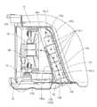
上記構成の冷蔵庫10において、機械室19は、図1に示すように、天井面61と、機械室19の底面を構成するコンプ台62と、冷凍室46の背面と機械室19とを仕切る上部ほど後方に傾斜した機械室前壁63と、左右の両側壁と、キャビネット16に対して着脱自在に取り付けられた背面板66とによってキャビネット16の背面下部に区画されている。なお、天井面61、機械室前壁63とは、キャビネット16の底板67によって一体に形成されている。  In therefrigerator 10 having the above configuration, as shown in FIG. 1, themachine room 19 includes an upper surface that divides theceiling surface 61, the comp stand 62 that forms the bottom surface of themachine room 19, the back surface of thefreezer room 46, and themachine room 19. The machineroom front wall 63 inclined rearward, left and right side walls, and aback plate 66 detachably attached to thecabinet 16 are partitioned at the lower back of thecabinet 16. Theceiling surface 61 and the machineroom front wall 63 are integrally formed by abottom plate 67 of thecabinet 16.

機械室19の幅方向一方側(例えば、機械室22の背面から見て左側)には、コンプ台62の上に防振ゴムを介して圧縮機51が載置されている。機械室19の幅方向他方側(例えば、機械室22の背面から右側)には、ファンユニット70が配設されている。このファンユニット70には、圧縮機51及び凝縮器56を冷却するための放熱ファン68が取り付けられている。また、ファンユニット70の後方のコンプ台62には、冷蔵用冷却器52及び冷凍用冷却器54から発生した除霜水を蒸発させるための蒸発皿72が載置されている。  On one side in the width direction of the machine room 19 (for example, the left side when viewed from the back of the machine room 22), thecompressor 51 is mounted on the comp table 62 via a vibration isolating rubber. Afan unit 70 is disposed on the other side in the width direction of the machine room 19 (for example, on the right side from the back of the machine room 22). Aheat radiating fan 68 for cooling thecompressor 51 and thecondenser 56 is attached to thefan unit 70. Further, anevaporating dish 72 for evaporating the defrosted water generated from therefrigeration cooler 52 and thefreezing cooler 54 is placed on thecomp stand 62 behind thefan unit 70.

凝縮器56は、図3に示すように、冷媒が内部を流れるアルミニウム製の冷媒チューブ56aと、この冷媒チューブ56aに設けられた板状の放熱フィン56bとを備えるフィンチューブコンデンサである。  As shown in FIG. 3, thecondenser 56 is a fin tube capacitor including analuminum refrigerant tube 56 a through which the refrigerant flows and plate-likeheat radiation fins 56 b provided on therefrigerant tube 56 a.

この凝縮器56は、左右に蛇行しながら機械室19の上部から下部へ配設された冷媒チューブ56aに、複数枚の板状の放熱フィン56bが互いに平行に取り付けられ、その全体形状が略直方体状をなしており、圧縮機51から吐出された冷媒が凝縮器56の上部から流入し、左右に蛇行しながら凝縮器56の下部へ流れる。  In thiscondenser 56, a plurality of plate-likeheat radiation fins 56b are attached in parallel to each other on arefrigerant tube 56a disposed from the upper part to the lower part of themachine room 19 while meandering left and right, and the overall shape thereof is a substantially rectangular parallelepiped. The refrigerant discharged from thecompressor 51 flows in from the upper part of thecondenser 56 and flows to the lower part of thecondenser 56 while meandering left and right.

冷媒チューブ56aのうち冷媒流れ方向上流側に位置する冷媒チューブ56aには、冷媒流れ方向下流側に位置する冷媒チューブ56aに比べて隣り合う放熱フィン56bの間隔が狭く設けられ放熱フィン56bが密に設けられている。つまり、凝縮器56には、冷媒流れ方向上流側に相当する凝縮器56の上部に放熱フィン56bが密に設けられた密集部56−1が形成、冷媒流れ方向下流側に相当する凝縮器56の下部に密集部56−1に比べて隣り合う放熱フィン56bの間隔が広く設けられ放熱フィン56bが疎に設けられた疎部56−2が形成されている。  Of therefrigerant tubes 56a, therefrigerant tubes 56a located on the upstream side in the refrigerant flow direction have narrower intervals between adjacent radiatingfins 56b than therefrigerant tubes 56a located on the downstream side in the refrigerant flow direction, and theradiating fins 56b are densely arranged. Is provided. In other words, thecondenser 56 is formed with a dense portion 56-1 in which theradiating fins 56b are densely provided on the upper portion of thecondenser 56 corresponding to the upstream side in the refrigerant flow direction, and thecondenser 56 corresponding to the downstream side in the refrigerant flow direction. A lower portion 56-2 is formed in which a space between adjacentheat dissipating fins 56b is wider than that of the dense portion 56-1 andheat dissipating fins 56b are provided sparsely.

また、密集部56−1が有する冷媒チューブ56aの冷媒流れ方向上流側には、放熱フィン56bが設けられていない冷媒チューブ56−3が接続されている。この冷媒チューブ56−3は、圧縮機51と凝縮器56とを接続する冷媒パイプを介して伝播する圧縮機51からの振動を吸収し、凝縮器56の密集部56−1や疎部56−2に該振動が伝播するのを防止する。  Moreover, the refrigerant | coolant tube 56-3 in which theradiation fin 56b is not provided is connected to the refrigerant | coolant flow direction upstream of the refrigerant |coolant tube 56a which the dense part 56-1 has. The refrigerant tube 56-3 absorbs vibration from thecompressor 51 propagating through the refrigerant pipe connecting thecompressor 51 and thecondenser 56, and the dense portion 56-1 and the sparse portion 56- of thecondenser 56 are absorbed. 2 to prevent the vibration from propagating.

図3及び図4に示すように、凝縮器56は、機械室前壁63に沿って機械室19内に配設されたダクト100内に設けられている。ダクト100は、ダクト本体102と、板状のダクト前面部104とにより構成される。  As shown in FIGS. 3 and 4, thecondenser 56 is provided in aduct 100 disposed in themachine room 19 along the machineroom front wall 63. Theduct 100 includes a ductmain body 102 and a plate-shaped ductfront surface portion 104.

ダクト本体102は、ダクト100の後面を仕切るダクト後面部106と、ダクト100の左右側部を仕切るダクト側面部108とが一体に形成されており、上下及び前面に開口する平面視において略コ字状をなしている。  In the ductmain body 102, a ductrear surface portion 106 that partitions the rear surface of theduct 100 and a ductside surface portion 108 that partitions the left and right side portions of theduct 100 are integrally formed. It has a shape.

ダクト本体102の下端部に設けられた係止爪120が、コンプ台62に穿設された固定孔(不図示)に係合するとともにネジ止めによりダクト本体102がコンプ台62に固定されている。このようにコンプ台62に固定されたダクト本体102はその下面開口部がコンプ台62に穿設された空気入口138に連通している(図4参照)。  Alocking claw 120 provided at the lower end of the ductmain body 102 engages with a fixing hole (not shown) drilled in thecomp base 62 and the ductmain body 102 is fixed to thecomp base 62 by screwing. . Thus, the ductmain body 102 fixed to the comp table 62 communicates with theair inlet 138 formed in the lower surface of the duct main body 102 (see FIG. 4).

ダクト前面部104は、機械室前壁63の後方においてダクト本体102の前面開口部を閉塞してダクト100の前面を仕切る部材である。ダクト前面部104は、機械室前壁63に沿うように上部ほど後方へ傾斜するように配設され、ダクト前面部104の上端部がダクト100内に設けられた凝縮器56の上方を覆うように後方に向かって湾曲している。  The ductfront surface portion 104 is a member that partitions the front surface of theduct 100 by closing the front opening of the ductmain body 102 behind the machineroom front wall 63. The ductfront surface portion 104 is disposed so as to be inclined rearward along the machineroom front wall 63 so that the upper end portion of the ductfront surface portion 104 covers the upper portion of thecondenser 56 provided in theduct 100. Curved backwards.

図3に示すように、ダクト前面部104の後面(ダクト後面部106との対向面)には、後方へ突出するボス部114及びチューブ固定部116が設けられている。チューブ固定部116に凝縮器56の冷媒チューブ56aを保持させダクト前面部104に凝縮器56を固定した状態でボス部114にねじ115を螺合する。これにより、凝縮器56が固定されたダクト前面部104がダクト本体102に対して着脱可能に取り付けられている。  As shown in FIG. 3, aboss portion 114 and atube fixing portion 116 that protrude rearward are provided on the rear surface of the duct front surface portion 104 (the surface facing the duct rear surface portion 106). Thescrew 115 is screwed into theboss 114 in a state where therefrigerant tube 56 a of thecondenser 56 is held by thetube fixing portion 116 and thecondenser 56 is fixed to the ductfront surface portion 104. Thereby, theduct front part 104 to which thecondenser 56 is fixed is detachably attached to the ductmain body 102.

このようにダクト前面部104がダクト本体102に取り付けられることで、ダクト本体102のダクト後面部106からダクト前面部104へ向けて突出する突片160が凝縮器56の冷媒チューブ56aに当接し、放熱フィン56bがダクト本体102及びダクト前面部104に接触しないように間隔をあけた状態で、凝縮器56がダクト本体102及びダクト前面部104によって区画されたダクト100内に配設されている。  By attaching the ductfront surface portion 104 to the ductmain body 102 in this way, the projectingpiece 160 protruding from the ductrear surface portion 106 of the ductmain body 102 toward the ductfront surface portion 104 abuts on therefrigerant tube 56a of thecondenser 56, Thecondenser 56 is disposed in theduct 100 defined by the ductmain body 102 and theduct front face 104 in a state where theheat radiating fins 56 b are spaced from each other so as not to contact the ductmain body 102 and the ductfront face 104.

また、ダクト本体102に設けられたダクト後面部106の上部には下方に陥没する開口部106aが設けられており、凝縮器56の上部に設けられた密集部56−1が、ダクト後面部106に設けられた開口部106aによってダクト100から露出し、凝縮器56の下部に設けられた疎部56−2が、ダクト後面部106、ダクト側面部108及びダクト前面部104によって覆われている。  In addition, anopening 106 a that sinks downward is provided in the upper portion of the ductrear surface portion 106 provided in the ductmain body 102, and the dense portion 56-1 provided in the upper portion of thecondenser 56 is provided in the ductrear surface portion 106. The sparse part 56-2 exposed from theduct 100 by theopening part 106a provided in the lower part of thecondenser 56 and covered with the ductrear face part 106, the ductside face part 108, and the ductfront face part 104.

ファンユニット70は、放熱ファン68をダクト本体102及び機械室19に固定するための部材であって、内側に放熱ファン68を配設する円形のベルマウス130が開口したユニット後面部124と、このユニット後面部124の下縁部及び左右側縁部から前方に向かって延びたユニット側面部126とを備える。  Thefan unit 70 is a member for fixing theheat radiating fan 68 to the ductmain body 102 and themachine room 19, and includes a unitrear surface portion 124 in which acircular bell mouth 130 in which theheat radiating fan 68 is disposed is opened. Aunit side surface 126 extending forward from the lower edge and the left and right edges of the unitrear surface 124.

ユニット後面部124の上部には、左右一方側に寄せて下方に陥没する凹部125が形成されており、冷媒チューブ56−3に接続され圧縮機51から吐出された冷媒を凝縮器56に供給する冷媒パイプと、凝縮器56を流れた冷媒を流通させる冷媒パイプとが、凹部125を通って機械室19とダクト100との間に配設されている。  Aconcave portion 125 is formed in the upper portion of the unitrear surface portion 124 so as to be depressed toward the left and right sides, and the refrigerant discharged from thecompressor 51 connected to the refrigerant tube 56-3 is supplied to thecondenser 56. A refrigerant pipe and a refrigerant pipe for circulating the refrigerant that has flowed through thecondenser 56 are disposed between themachine room 19 and theduct 100 through therecess 125.

放熱ファン68は、モータから径方向外方へ突出した固定腕132の外端部に形成されたリング部134をユニット後面部124にネジ止めすることで、ベルマウス130の内側において吸込口68aを前方に向けてファンユニット70に固定される。  Theheat dissipating fan 68 is formed by screwing aring portion 134 formed at the outer end portion of the fixedarm 132 projecting radially outward from the motor to the unitrear surface portion 124, so that thesuction port 68 a is formed inside thebell mouth 130. It is fixed to thefan unit 70 toward the front.

ファンユニット70のユニット側面部126の前端は、ダクト本体102のダクト後面部106に設けられた開口部106aの下縁部及び左右側縁部に取り付けられている。これにより、ファンユニット70に設けられた放熱ファン68が、開口部106aの後方に配置され、開口部106aを介してダクト100内に配設された凝縮器56の密集部56−1に対向している。  The front end of theunit side surface 126 of thefan unit 70 is attached to the lower edge and the left and right edges of the opening 106 a provided in the ductrear surface 106 of theduct body 102. Thereby, theheat radiating fan 68 provided in thefan unit 70 is disposed behind theopening 106a and faces the dense portion 56-1 of thecondenser 56 disposed in theduct 100 via theopening 106a. ing.

また、図4に示すように、ファンユニット70のユニット後面部124の上端には、後方へ延びてから上方へ突出する略L字状の固定部材156が設けられており、機械室19の天井面61にファンユニット70の上端を当接しファンユニット70の上面開口部を閉塞した状態で固定部材156を機械室19の上縁部に対してネジ止めすることで、ファンユニット70が機械室19に固定されている。  As shown in FIG. 4, a substantially L-shaped fixingmember 156 that extends rearward and protrudes upward is provided at the upper end of the unitrear surface portion 124 of thefan unit 70. The fixingunit 156 is screwed to the upper edge portion of themachine room 19 in a state where the upper end of thefan unit 70 is brought into contact with thesurface 61 and the upper surface opening of thefan unit 70 is closed, so that thefan unit 70 is secured to themachine room 19. It is fixed to.

このような構成の冷蔵庫10では、圧縮機51を駆動させて冷凍サイクル50の動作を開始するとともに放熱ファン68を回転することで、圧縮機51から吐出されたガス状の冷媒を凝縮器56において放熱冷却する。  In therefrigerator 10 having such a configuration, thecompressor 51 is driven to start the operation of therefrigeration cycle 50 and theheat dissipating fan 68 is rotated so that the gaseous refrigerant discharged from thecompressor 51 is discharged in thecondenser 56. Cool with heat dissipation.

具体的には、放熱ファン68が回転すると、図4に示すように、機械室19の下方の空気は、コンプ台62に穿設された空気入口138からダクト100内に取り込まれ、ダクト100内をダクト前面部104に沿って凝縮器56の疎部56−2及び密集部56−1と順次熱交換しながら上方へ流れ、ダクト本体102に設けられた開口部106aを通って放熱ファン68の吸込口68aに吸い込まれ、放熱ファン68後方の機械室19内に吐出される。  Specifically, when theheat radiating fan 68 rotates, the air below themachine room 19 is taken into theduct 100 from theair inlet 138 formed in thecompressor base 62 as shown in FIG. Of theheat radiating fan 68 through theopening 106a provided in the ductmain body 102 through the ductfront surface portion 104 while sequentially exchanging heat with the sparse portion 56-2 and the dense portion 56-1 of thecondenser 56. It is sucked into thesuction port 68a and discharged into themachine room 19 behind theheat dissipation fan 68.

以上のように、本実施形態の冷蔵庫10では、ダクト100内に設けられた凝縮器56は、ダクト100の下部、つまり、ダクト100の上流側に放熱フィン56bの間隔が比較的大きく空気抵抗の小さい疎部56−2が配置され、ダクト100の上部、つまりダクト100の下流側に放熱フィン56bが密に設けられた密集部56−1が配置されている。そのため、空気入口138近傍での圧力損失を抑えて機械室19の下方から空気がダクト100内へ取り込まれやすくなり疎部56−2において風量を大きくして放熱効率を高めつつ、密集部56−1において放熱面積を大きくして放熱効率を高めることができ、凝縮器56全体の放熱効率を向上させることができる。  As described above, in therefrigerator 10 of the present embodiment, thecondenser 56 provided in theduct 100 has a relatively large space between theradiation fins 56b at the lower part of theduct 100, that is, on the upstream side of theduct 100. A small sparse part 56-2 is arranged, and a dense part 56-1 in which heatradiation fins 56b are densely arranged is arranged in the upper part of theduct 100, that is, on the downstream side of theduct 100. Therefore, pressure loss in the vicinity of theair inlet 138 is suppressed, and air is easily taken into theduct 100 from the lower side of themachine room 19. The air density is increased in the sparse part 56-2 to increase the heat radiation efficiency, and the dense part 56- 1, the heat dissipation area can be increased to increase the heat dissipation efficiency, and the heat dissipation efficiency of theentire condenser 56 can be improved.

しかも、放熱フィン56bが密に設けられた密集部56−1には、ダクト後面部106に設けられた開口部106aを介して放熱ファン68の吸込口68aが対向しており、放熱ファン68の吸込気流がダクト本体102に遮られることがなく、密集部56−1の空気を放熱ファン68で直接吸い込むことができるため、密集部56−1に放熱フィン56bを密に設けることで空気抵抗が増大しても圧力損失を抑えることができ、凝縮器56の放熱効率を向上させることができる。  In addition, the dense portion 56-1 in which the radiatingfins 56b are densely arranged is opposed to thesuction port 68a of the radiatingfan 68 through theopening 106a provided in the ductrear surface portion 106. Since the suction airflow is not blocked by theduct body 102 and the air in the dense portion 56-1 can be directly sucked by theheat radiating fan 68, air resistance is reduced by providing theheat radiating fins 56b densely in the dense portion 56-1. Even if it increases, pressure loss can be suppressed and the heat dissipation efficiency of thecondenser 56 can be improved.

また、本実施形態において凝縮器56は、冷媒流れ方向上流側に密集部56−1が形成され、冷媒流れ方向下流側に疎部56−2が形成されており、圧縮機51から吐出された高温の冷媒は、放熱フィン56bが密に設けられた放熱性能の高い密集部56−1の冷媒チューブ56aを流れ冷却されてから疎部56−2の冷媒チューブ56aを流れる。そのため、圧縮機51から吐出された後の早い段階において高温の冷媒を効率的に放熱させることができ、凝縮器56の放熱効率を向上させることができる。  Further, in the present embodiment, thecondenser 56 has a dense portion 56-1 formed on the upstream side in the refrigerant flow direction and a sparse portion 56-2 formed on the downstream side in the refrigerant flow direction, and is discharged from thecompressor 51. The high-temperature refrigerant flows through therefrigerant tube 56a of the sparse part 56-2 after being cooled down after flowing through therefrigerant tube 56a of the dense part 56-1 having high heat dissipation performance provided with theheat radiation fins 56b densely. Therefore, the high-temperature refrigerant can be efficiently radiated at an early stage after being discharged from thecompressor 51, and the heat dissipation efficiency of thecondenser 56 can be improved.

更にまた、本実施形態では、密集部56−1が有する冷媒チューブ56aの冷媒流れ方向上流側に、放熱フィン56bが設けられていない冷媒チューブ56−3が接続されているため、圧縮機51で発生する振動が、冷媒チューブ56−3において吸収され圧縮機51と凝縮器56とを接続する冷媒パイプを介して凝縮器56の密集部56−1や疎部56−2に伝播するのを抑えることができ、密集部56−1や疎部56−2に設けられた放熱フィン56bが接触することによる異音の発生や放熱フィン56bの摩耗を抑えることができる。  Furthermore, in the present embodiment, since the refrigerant tube 56-3 not provided with theradiation fins 56b is connected to the upstream side in the refrigerant flow direction of therefrigerant tube 56a of the dense portion 56-1, thecompressor 51 The generated vibration is absorbed in the refrigerant tube 56-3 and is prevented from propagating to the dense part 56-1 and the sparse part 56-2 of thecondenser 56 via the refrigerant pipe connecting thecompressor 51 and thecondenser 56. Therefore, it is possible to suppress the generation of noise and the wear of the radiatingfins 56b due to the contact of the radiatingfins 56b provided in the dense portion 56-1 and the sparse portion 56-2.

なお、上記した実施形態は例として提示したものであり、発明の範囲を限定することは意図していない。これらの実施形態は、その他の様々な形態で実施されることが可能であり、発明の要旨を逸脱しない範囲で、種々の省略、置き換え、変更を行うことができる。これらの実施形態は、発明の範囲や要旨に含まれると同様に、特許請求の範囲に記載された発明とその均等の範囲に含まれるものである。  The above-described embodiments are presented as examples, and are not intended to limit the scope of the invention. These embodiments can be implemented in various other forms, and various omissions, replacements, and changes can be made without departing from the scope of the invention. These embodiments are included in the scope and gist of the invention, and are also included in the invention described in the scope of claims and the equivalents thereof.

16…キャビネット 19…機械室 20…冷蔵空間
40…冷凍空間 50…冷凍サイクル 51…圧縮機
52…冷蔵用冷却器 54…冷凍用冷却器 56…凝縮器
56−1…密集部 56−2…疎部 56a…冷媒チューブ
56b…放熱フィン 61…天井面 62…コンプ台
63…機械室前壁 66…背面板 68…放熱ファン
68a…吸込口 70…ファンユニット 72…蒸発皿
100…ダクト 102…ダクト本体 104…ダクト前面部
106…ダクト後面部 106a…開口部 108…ダクト側面部
124…ユニット後面部 126…ユニット側面部 138…空気入口
DESCRIPTION OFSYMBOLS 16 ...Cabinet 19 ...Machine room 20 ...Refrigeration space 40 ...Refrigeration space 50 ...Refrigeration cycle 51 ...Compressor 52 ...Refrigeration cooler 54 ...Refrigeration cooler 56 ... Condenser 56-1 ... Condensation part 56-2 ...Sparse Part 56a ...Refrigerant tube 56b ...Radiation fin 61 ...Ceiling surface 62 ... Comp stand 63 ... Machine roomfront wall 66 ... Back plate 68 ...Radiation fan 68a ...Suction port 70 ...Fan unit 72 ... Evaporatingdish 100 ...Duct 102 ... Duct body DESCRIPTION OFSYMBOLS 104 ... Ductfront surface part 106 ... Ductrear surface part 106a ... Openingpart 108 ... Ductside surface part 124 ... Unitrear surface part 126 ... Unitside surface part 138 ... Air inlet

Claims (3)

Translated fromJapanese
キャビネットの背面下部に設けられた機械室と、
前記機械室と冷蔵庫内とを前後に仕切る機械室前壁と、
前記機械室前壁に沿って前記機械室内に設けられ前記機械室の下方より空気を吸い込むダクトと、
前記ダクト内に設けられた凝縮器と、
前記機械室内における前記ダクトの後方に設けられたファンとを備え、
前記凝縮器は、冷媒が流れる冷媒チューブと、前記冷媒チューブに設けられた放熱フィンとを備え、前記ダクトの上流側に配置された疎部より前記ダクトの下流側に配置された密集部に前記放熱フィンが密に設けられ、
前記ダクトは、前記凝縮器における前記密集部の後方に開口部を備え、
前記ファンは、前記開口部を介して前記密集部に対向することを特徴とする冷蔵庫。
A machine room in the lower back of the cabinet;
A machine room front wall that divides the machine room and the inside of the refrigerator back and forth,
A duct that is provided in the machine room along the front wall of the machine room and sucks air from below the machine room;
A condenser provided in the duct;
A fan provided behind the duct in the machine room,
The condenser includes a refrigerant tube through which a refrigerant flows and a heat dissipating fin provided in the refrigerant tube, and the condensing unit disposed on the downstream side of the duct from the sparse portion disposed on the upstream side of the duct. Radiation fins are densely installed,
The duct includes an opening portion behind the dense portion in the condenser,
The refrigerator, wherein the fan faces the dense portion through the opening.
前記密集部に設けられた前記冷媒チューブが冷媒流れ方向上流側に位置することを特徴とする請求項1に記載の冷蔵庫。  The refrigerator according to claim 1, wherein the refrigerant tube provided in the dense portion is located on the upstream side in the refrigerant flow direction. 前記凝縮器は、前記密集部に設けられた前記冷媒チューブの冷媒流れ方向上流側に前記放熱フィンが設けられていない冷媒チューブを備えることを特徴とする請求項1又は2に記載の冷蔵庫。  The refrigerator according to claim 1 or 2, wherein the condenser includes a refrigerant tube not provided with the radiation fins on the upstream side in the refrigerant flow direction of the refrigerant tube provided in the dense portion.
JP2011130421A2011-06-102011-06-10RefrigeratorWithdrawnJP2012255638A (en)

Priority Applications (1)

Application NumberPriority DateFiling DateTitle
JP2011130421AJP2012255638A (en)2011-06-102011-06-10Refrigerator

Applications Claiming Priority (1)

Application NumberPriority DateFiling DateTitle
JP2011130421AJP2012255638A (en)2011-06-102011-06-10Refrigerator

Publications (1)

Publication NumberPublication Date
JP2012255638Atrue JP2012255638A (en)2012-12-27

Family

ID=47527342

Family Applications (1)

Application NumberTitlePriority DateFiling Date
JP2011130421AWithdrawnJP2012255638A (en)2011-06-102011-06-10Refrigerator

Country Status (1)

CountryLink
JP (1)JP2012255638A (en)

Cited By (4)

* Cited by examiner, † Cited by third party
Publication numberPriority datePublication dateAssigneeTitle
WO2015086421A1 (en)*2013-12-112015-06-18BSH Hausgeräte GmbHDomestic refrigeration appliance having a machinery compartment and a fan housing installed on a crossbar of the machinery compartment, and method for installing such a fan in the machinery compartment
CN105953481A (en)*2016-04-212016-09-21合肥华凌股份有限公司Condenser and refrigerator comprising same
JP2022178633A (en)*2021-05-202022-12-02三星電子株式会社 refrigerator
CN116294306A (en)*2021-12-202023-06-23青岛海尔电冰箱有限公司Refrigerator and condenser assembly thereof

Cited By (7)

* Cited by examiner, † Cited by third party
Publication numberPriority datePublication dateAssigneeTitle
WO2015086421A1 (en)*2013-12-112015-06-18BSH Hausgeräte GmbHDomestic refrigeration appliance having a machinery compartment and a fan housing installed on a crossbar of the machinery compartment, and method for installing such a fan in the machinery compartment
CN105953481A (en)*2016-04-212016-09-21合肥华凌股份有限公司Condenser and refrigerator comprising same
WO2017181496A1 (en)*2016-04-212017-10-26合肥华凌股份有限公司Condenser and refrigerator having same
US10808986B2 (en)2016-04-212020-10-20Hefei Hualing Co., Ltd.Condenser and refrigerator having same
JP2022178633A (en)*2021-05-202022-12-02三星電子株式会社 refrigerator
CN116294306A (en)*2021-12-202023-06-23青岛海尔电冰箱有限公司Refrigerator and condenser assembly thereof
WO2023115939A1 (en)*2021-12-202023-06-29青岛海尔电冰箱有限公司Refrigerator and condenser assembly thereof

Similar Documents

PublicationPublication DateTitle
KR20150063175A (en)Refrigerator
TW201738518A (en)Refrigerator
JP2013019623A (en)Refrigerator
JP6388378B2 (en) refrigerator
CN104380015B (en) refrigerator
JP2012255638A (en)Refrigerator
JP2009079778A (en) refrigerator
JP2018048798A (en)refrigerator
JP2006138609A (en) refrigerator
KR101650379B1 (en)Refrigerator
JP5575532B2 (en) refrigerator
JP2009002596A (en) Cooling unit
JP7209554B2 (en) refrigerator
JP2003287342A (en) refrigerator
CN103575025B (en)Refrigerating and cold storage refrigerator
JP5702561B2 (en) refrigerator
WO2022037718A1 (en)Refrigerator having condenser arranged in compressor cabin
JP2011257087A (en)Refrigerating device for freezer
JP7588298B2 (en) refrigerator
JP2011080692A (en)Refrigerator
JP2023041133A (en)refrigerator
JP2007046865A (en) refrigerator
CN220489501U (en)Embedded refrigerator ventilation system
JP2008292093A (en) refrigerator
KR100501948B1 (en)Air circulation apparatus for small refrigerator

Legal Events

DateCodeTitleDescription
A711Notification of change in applicant

Free format text:JAPANESE INTERMEDIATE CODE: A712

Effective date:20140204

A300Withdrawal of application because of no request for examination

Free format text:JAPANESE INTERMEDIATE CODE: A300

Effective date:20140902


[8]ページ先頭

©2009-2025 Movatter.jp