JP2012250090A - Administration instrument for medical use - Google Patents
Administration instrument for medical useDownload PDFInfo
- Publication number
- JP2012250090A JP2012250090AJP2012210804AJP2012210804AJP2012250090AJP 2012250090 AJP2012250090 AJP 2012250090AJP 2012210804 AJP2012210804 AJP 2012210804AJP 2012210804 AJP2012210804 AJP 2012210804AJP 2012250090 AJP2012250090 AJP 2012250090A
- Authority
- JP
- Japan
- Prior art keywords
- injection
- administration device
- button
- medical administration
- injection button
- Prior art date
- Legal status (The legal status is an assumption and is not a legal conclusion. Google has not performed a legal analysis and makes no representation as to the accuracy of the status listed.)
- Pending
Links
Images


Classifications
- A—HUMAN NECESSITIES
- A61—MEDICAL OR VETERINARY SCIENCE; HYGIENE
- A61M—DEVICES FOR INTRODUCING MEDIA INTO, OR ONTO, THE BODY; DEVICES FOR TRANSDUCING BODY MEDIA OR FOR TAKING MEDIA FROM THE BODY; DEVICES FOR PRODUCING OR ENDING SLEEP OR STUPOR
- A61M5/00—Devices for bringing media into the body in a subcutaneous, intra-vascular or intramuscular way; Accessories therefor, e.g. filling or cleaning devices, arm-rests
- A61M5/178—Syringes
- A61M5/31—Details
- A61M5/315—Pistons; Piston-rods; Guiding, blocking or restricting the movement of the rod or piston; Appliances on the rod for facilitating dosing ; Dosing mechanisms
- A61M5/31596—Pistons; Piston-rods; Guiding, blocking or restricting the movement of the rod or piston; Appliances on the rod for facilitating dosing ; Dosing mechanisms comprising means for injection of two or more media, e.g. by mixing
- A—HUMAN NECESSITIES
- A61—MEDICAL OR VETERINARY SCIENCE; HYGIENE
- A61M—DEVICES FOR INTRODUCING MEDIA INTO, OR ONTO, THE BODY; DEVICES FOR TRANSDUCING BODY MEDIA OR FOR TAKING MEDIA FROM THE BODY; DEVICES FOR PRODUCING OR ENDING SLEEP OR STUPOR
- A61M5/00—Devices for bringing media into the body in a subcutaneous, intra-vascular or intramuscular way; Accessories therefor, e.g. filling or cleaning devices, arm-rests
- A61M5/178—Syringes
- A61M5/31—Details
- A61M5/315—Pistons; Piston-rods; Guiding, blocking or restricting the movement of the rod or piston; Appliances on the rod for facilitating dosing ; Dosing mechanisms
- A61M5/31511—Piston or piston-rod constructions, e.g. connection of piston with piston-rod
- A—HUMAN NECESSITIES
- A61—MEDICAL OR VETERINARY SCIENCE; HYGIENE
- A61M—DEVICES FOR INTRODUCING MEDIA INTO, OR ONTO, THE BODY; DEVICES FOR TRANSDUCING BODY MEDIA OR FOR TAKING MEDIA FROM THE BODY; DEVICES FOR PRODUCING OR ENDING SLEEP OR STUPOR
- A61M5/00—Devices for bringing media into the body in a subcutaneous, intra-vascular or intramuscular way; Accessories therefor, e.g. filling or cleaning devices, arm-rests
- A61M5/178—Syringes
- A61M5/31—Details
- A61M5/315—Pistons; Piston-rods; Guiding, blocking or restricting the movement of the rod or piston; Appliances on the rod for facilitating dosing ; Dosing mechanisms
- A61M5/31565—Administration mechanisms, i.e. constructional features, modes of administering a dose
- A61M5/31566—Means improving security or handling thereof
- A61M5/31571—Means preventing accidental administration
- A—HUMAN NECESSITIES
- A61—MEDICAL OR VETERINARY SCIENCE; HYGIENE
- A61M—DEVICES FOR INTRODUCING MEDIA INTO, OR ONTO, THE BODY; DEVICES FOR TRANSDUCING BODY MEDIA OR FOR TAKING MEDIA FROM THE BODY; DEVICES FOR PRODUCING OR ENDING SLEEP OR STUPOR
- A61M5/00—Devices for bringing media into the body in a subcutaneous, intra-vascular or intramuscular way; Accessories therefor, e.g. filling or cleaning devices, arm-rests
- A61M5/178—Syringes
- A61M5/31—Details
- A61M5/315—Pistons; Piston-rods; Guiding, blocking or restricting the movement of the rod or piston; Appliances on the rod for facilitating dosing ; Dosing mechanisms
- A61M5/31565—Administration mechanisms, i.e. constructional features, modes of administering a dose
- A61M5/31576—Constructional features or modes of drive mechanisms for piston rods
- A61M5/31583—Constructional features or modes of drive mechanisms for piston rods based on rotational translation, i.e. movement of piston rod is caused by relative rotation between the user activated actuator and the piston rod
- A61M5/31585—Constructional features or modes of drive mechanisms for piston rods based on rotational translation, i.e. movement of piston rod is caused by relative rotation between the user activated actuator and the piston rod performed by axially moving actuator, e.g. an injection button
- A—HUMAN NECESSITIES
- A61—MEDICAL OR VETERINARY SCIENCE; HYGIENE
- A61M—DEVICES FOR INTRODUCING MEDIA INTO, OR ONTO, THE BODY; DEVICES FOR TRANSDUCING BODY MEDIA OR FOR TAKING MEDIA FROM THE BODY; DEVICES FOR PRODUCING OR ENDING SLEEP OR STUPOR
- A61M5/00—Devices for bringing media into the body in a subcutaneous, intra-vascular or intramuscular way; Accessories therefor, e.g. filling or cleaning devices, arm-rests
- A61M5/46—Devices for bringing media into the body in a subcutaneous, intra-vascular or intramuscular way; Accessories therefor, e.g. filling or cleaning devices, arm-rests having means for controlling depth of insertion
- A—HUMAN NECESSITIES
- A61—MEDICAL OR VETERINARY SCIENCE; HYGIENE
- A61M—DEVICES FOR INTRODUCING MEDIA INTO, OR ONTO, THE BODY; DEVICES FOR TRANSDUCING BODY MEDIA OR FOR TAKING MEDIA FROM THE BODY; DEVICES FOR PRODUCING OR ENDING SLEEP OR STUPOR
- A61M5/00—Devices for bringing media into the body in a subcutaneous, intra-vascular or intramuscular way; Accessories therefor, e.g. filling or cleaning devices, arm-rests
- A61M5/178—Syringes
- A61M5/24—Ampoule syringes, i.e. syringes with needle for use in combination with replaceable ampoules or carpules, e.g. automatic
- A61M2005/2403—Ampoule inserted into the ampoule holder
- A61M2005/2407—Ampoule inserted into the ampoule holder from the rear
- A—HUMAN NECESSITIES
- A61—MEDICAL OR VETERINARY SCIENCE; HYGIENE
- A61M—DEVICES FOR INTRODUCING MEDIA INTO, OR ONTO, THE BODY; DEVICES FOR TRANSDUCING BODY MEDIA OR FOR TAKING MEDIA FROM THE BODY; DEVICES FOR PRODUCING OR ENDING SLEEP OR STUPOR
- A61M5/00—Devices for bringing media into the body in a subcutaneous, intra-vascular or intramuscular way; Accessories therefor, e.g. filling or cleaning devices, arm-rests
- A61M5/178—Syringes
- A61M5/24—Ampoule syringes, i.e. syringes with needle for use in combination with replaceable ampoules or carpules, e.g. automatic
- A61M2005/2485—Ampoule holder connected to rest of syringe
- A61M2005/2488—Ampoule holder connected to rest of syringe via rotation, e.g. threads or bayonet
- A—HUMAN NECESSITIES
- A61—MEDICAL OR VETERINARY SCIENCE; HYGIENE
- A61M—DEVICES FOR INTRODUCING MEDIA INTO, OR ONTO, THE BODY; DEVICES FOR TRANSDUCING BODY MEDIA OR FOR TAKING MEDIA FROM THE BODY; DEVICES FOR PRODUCING OR ENDING SLEEP OR STUPOR
- A61M5/00—Devices for bringing media into the body in a subcutaneous, intra-vascular or intramuscular way; Accessories therefor, e.g. filling or cleaning devices, arm-rests
- A61M5/178—Syringes
- A61M5/24—Ampoule syringes, i.e. syringes with needle for use in combination with replaceable ampoules or carpules, e.g. automatic
- A61M2005/2485—Ampoule holder connected to rest of syringe
- A61M2005/2496—Ampoule holder connected to rest of syringe via pivot
- A—HUMAN NECESSITIES
- A61—MEDICAL OR VETERINARY SCIENCE; HYGIENE
- A61M—DEVICES FOR INTRODUCING MEDIA INTO, OR ONTO, THE BODY; DEVICES FOR TRANSDUCING BODY MEDIA OR FOR TAKING MEDIA FROM THE BODY; DEVICES FOR PRODUCING OR ENDING SLEEP OR STUPOR
- A61M5/00—Devices for bringing media into the body in a subcutaneous, intra-vascular or intramuscular way; Accessories therefor, e.g. filling or cleaning devices, arm-rests
- A61M5/178—Syringes
- A61M5/31—Details
- A61M2005/3123—Details having air entrapping or venting means, e.g. purging channels in pistons
- A—HUMAN NECESSITIES
- A61—MEDICAL OR VETERINARY SCIENCE; HYGIENE
- A61M—DEVICES FOR INTRODUCING MEDIA INTO, OR ONTO, THE BODY; DEVICES FOR TRANSDUCING BODY MEDIA OR FOR TAKING MEDIA FROM THE BODY; DEVICES FOR PRODUCING OR ENDING SLEEP OR STUPOR
- A61M5/00—Devices for bringing media into the body in a subcutaneous, intra-vascular or intramuscular way; Accessories therefor, e.g. filling or cleaning devices, arm-rests
- A61M5/178—Syringes
- A61M5/31—Details
- A61M2005/3125—Details specific display means, e.g. to indicate dose setting
- A—HUMAN NECESSITIES
- A61—MEDICAL OR VETERINARY SCIENCE; HYGIENE
- A61M—DEVICES FOR INTRODUCING MEDIA INTO, OR ONTO, THE BODY; DEVICES FOR TRANSDUCING BODY MEDIA OR FOR TAKING MEDIA FROM THE BODY; DEVICES FOR PRODUCING OR ENDING SLEEP OR STUPOR
- A61M5/00—Devices for bringing media into the body in a subcutaneous, intra-vascular or intramuscular way; Accessories therefor, e.g. filling or cleaning devices, arm-rests
- A61M5/178—Syringes
- A61M5/31—Details
- A61M5/3129—Syringe barrels
- A61M2005/3132—Syringe barrels having flow passages for injection agents at the distal end of the barrel to bypass a sealing stopper after its displacement to this end due to internal pressure increase
- A—HUMAN NECESSITIES
- A61—MEDICAL OR VETERINARY SCIENCE; HYGIENE
- A61M—DEVICES FOR INTRODUCING MEDIA INTO, OR ONTO, THE BODY; DEVICES FOR TRANSDUCING BODY MEDIA OR FOR TAKING MEDIA FROM THE BODY; DEVICES FOR PRODUCING OR ENDING SLEEP OR STUPOR
- A61M5/00—Devices for bringing media into the body in a subcutaneous, intra-vascular or intramuscular way; Accessories therefor, e.g. filling or cleaning devices, arm-rests
- A61M5/178—Syringes
- A61M5/31—Details
- A61M5/315—Pistons; Piston-rods; Guiding, blocking or restricting the movement of the rod or piston; Appliances on the rod for facilitating dosing ; Dosing mechanisms
- A61M5/31511—Piston or piston-rod constructions, e.g. connection of piston with piston-rod
- A61M2005/3152—Piston or piston-rod constructions, e.g. connection of piston with piston-rod including gearings to multiply or attenuate the piston displacing force
- A—HUMAN NECESSITIES
- A61—MEDICAL OR VETERINARY SCIENCE; HYGIENE
- A61M—DEVICES FOR INTRODUCING MEDIA INTO, OR ONTO, THE BODY; DEVICES FOR TRANSDUCING BODY MEDIA OR FOR TAKING MEDIA FROM THE BODY; DEVICES FOR PRODUCING OR ENDING SLEEP OR STUPOR
- A61M2205/00—General characteristics of the apparatus
- A61M2205/13—General characteristics of the apparatus with means for the detection of operative contact with patient, e.g. lip sensor
- A—HUMAN NECESSITIES
- A61—MEDICAL OR VETERINARY SCIENCE; HYGIENE
- A61M—DEVICES FOR INTRODUCING MEDIA INTO, OR ONTO, THE BODY; DEVICES FOR TRANSDUCING BODY MEDIA OR FOR TAKING MEDIA FROM THE BODY; DEVICES FOR PRODUCING OR ENDING SLEEP OR STUPOR
- A61M2205/00—General characteristics of the apparatus
- A61M2205/14—Detection of the presence or absence of a tube, a connector or a container in an apparatus
- A—HUMAN NECESSITIES
- A61—MEDICAL OR VETERINARY SCIENCE; HYGIENE
- A61M—DEVICES FOR INTRODUCING MEDIA INTO, OR ONTO, THE BODY; DEVICES FOR TRANSDUCING BODY MEDIA OR FOR TAKING MEDIA FROM THE BODY; DEVICES FOR PRODUCING OR ENDING SLEEP OR STUPOR
- A61M2205/00—General characteristics of the apparatus
- A61M2205/50—General characteristics of the apparatus with microprocessors or computers
- A—HUMAN NECESSITIES
- A61—MEDICAL OR VETERINARY SCIENCE; HYGIENE
- A61M—DEVICES FOR INTRODUCING MEDIA INTO, OR ONTO, THE BODY; DEVICES FOR TRANSDUCING BODY MEDIA OR FOR TAKING MEDIA FROM THE BODY; DEVICES FOR PRODUCING OR ENDING SLEEP OR STUPOR
- A61M2205/00—General characteristics of the apparatus
- A61M2205/58—Means for facilitating use, e.g. by people with impaired vision
- A61M2205/581—Means for facilitating use, e.g. by people with impaired vision by audible feedback
- A—HUMAN NECESSITIES
- A61—MEDICAL OR VETERINARY SCIENCE; HYGIENE
- A61M—DEVICES FOR INTRODUCING MEDIA INTO, OR ONTO, THE BODY; DEVICES FOR TRANSDUCING BODY MEDIA OR FOR TAKING MEDIA FROM THE BODY; DEVICES FOR PRODUCING OR ENDING SLEEP OR STUPOR
- A61M2205/00—General characteristics of the apparatus
- A61M2205/58—Means for facilitating use, e.g. by people with impaired vision
- A61M2205/583—Means for facilitating use, e.g. by people with impaired vision by visual feedback
- A—HUMAN NECESSITIES
- A61—MEDICAL OR VETERINARY SCIENCE; HYGIENE
- A61M—DEVICES FOR INTRODUCING MEDIA INTO, OR ONTO, THE BODY; DEVICES FOR TRANSDUCING BODY MEDIA OR FOR TAKING MEDIA FROM THE BODY; DEVICES FOR PRODUCING OR ENDING SLEEP OR STUPOR
- A61M5/00—Devices for bringing media into the body in a subcutaneous, intra-vascular or intramuscular way; Accessories therefor, e.g. filling or cleaning devices, arm-rests
- A61M5/178—Syringes
- A61M5/24—Ampoule syringes, i.e. syringes with needle for use in combination with replaceable ampoules or carpules, e.g. automatic
- A61M5/2448—Ampoule syringes, i.e. syringes with needle for use in combination with replaceable ampoules or carpules, e.g. automatic comprising means for injection of two or more media, e.g. by mixing
- A—HUMAN NECESSITIES
- A61—MEDICAL OR VETERINARY SCIENCE; HYGIENE
- A61M—DEVICES FOR INTRODUCING MEDIA INTO, OR ONTO, THE BODY; DEVICES FOR TRANSDUCING BODY MEDIA OR FOR TAKING MEDIA FROM THE BODY; DEVICES FOR PRODUCING OR ENDING SLEEP OR STUPOR
- A61M5/00—Devices for bringing media into the body in a subcutaneous, intra-vascular or intramuscular way; Accessories therefor, e.g. filling or cleaning devices, arm-rests
- A61M5/178—Syringes
- A61M5/31—Details
- A61M5/3129—Syringe barrels
- A—HUMAN NECESSITIES
- A61—MEDICAL OR VETERINARY SCIENCE; HYGIENE
- A61M—DEVICES FOR INTRODUCING MEDIA INTO, OR ONTO, THE BODY; DEVICES FOR TRANSDUCING BODY MEDIA OR FOR TAKING MEDIA FROM THE BODY; DEVICES FOR PRODUCING OR ENDING SLEEP OR STUPOR
- A61M5/00—Devices for bringing media into the body in a subcutaneous, intra-vascular or intramuscular way; Accessories therefor, e.g. filling or cleaning devices, arm-rests
- A61M5/178—Syringes
- A61M5/31—Details
- A61M5/3146—Priming, e.g. purging, reducing backlash or clearance
- A—HUMAN NECESSITIES
- A61—MEDICAL OR VETERINARY SCIENCE; HYGIENE
- A61M—DEVICES FOR INTRODUCING MEDIA INTO, OR ONTO, THE BODY; DEVICES FOR TRANSDUCING BODY MEDIA OR FOR TAKING MEDIA FROM THE BODY; DEVICES FOR PRODUCING OR ENDING SLEEP OR STUPOR
- A61M5/00—Devices for bringing media into the body in a subcutaneous, intra-vascular or intramuscular way; Accessories therefor, e.g. filling or cleaning devices, arm-rests
- A61M5/178—Syringes
- A61M5/31—Details
- A61M5/315—Pistons; Piston-rods; Guiding, blocking or restricting the movement of the rod or piston; Appliances on the rod for facilitating dosing ; Dosing mechanisms
- A61M5/31533—Dosing mechanisms, i.e. setting a dose
- A61M5/31545—Setting modes for dosing
- A61M5/31548—Mechanically operated dose setting member
- A61M5/3155—Mechanically operated dose setting member by rotational movement of dose setting member, e.g. during setting or filling of a syringe
- A61M5/31553—Mechanically operated dose setting member by rotational movement of dose setting member, e.g. during setting or filling of a syringe without axial movement of dose setting member
- A—HUMAN NECESSITIES
- A61—MEDICAL OR VETERINARY SCIENCE; HYGIENE
- A61M—DEVICES FOR INTRODUCING MEDIA INTO, OR ONTO, THE BODY; DEVICES FOR TRANSDUCING BODY MEDIA OR FOR TAKING MEDIA FROM THE BODY; DEVICES FOR PRODUCING OR ENDING SLEEP OR STUPOR
- A61M5/00—Devices for bringing media into the body in a subcutaneous, intra-vascular or intramuscular way; Accessories therefor, e.g. filling or cleaning devices, arm-rests
- A61M5/178—Syringes
- A61M5/31—Details
- A61M5/315—Pistons; Piston-rods; Guiding, blocking or restricting the movement of the rod or piston; Appliances on the rod for facilitating dosing ; Dosing mechanisms
- A61M5/31533—Dosing mechanisms, i.e. setting a dose
- A61M5/31545—Setting modes for dosing
- A61M5/31548—Mechanically operated dose setting member
- A61M5/31556—Accuracy improving means
- A—HUMAN NECESSITIES
- A61—MEDICAL OR VETERINARY SCIENCE; HYGIENE
- A61M—DEVICES FOR INTRODUCING MEDIA INTO, OR ONTO, THE BODY; DEVICES FOR TRANSDUCING BODY MEDIA OR FOR TAKING MEDIA FROM THE BODY; DEVICES FOR PRODUCING OR ENDING SLEEP OR STUPOR
- A61M5/00—Devices for bringing media into the body in a subcutaneous, intra-vascular or intramuscular way; Accessories therefor, e.g. filling or cleaning devices, arm-rests
- A61M5/178—Syringes
- A61M5/31—Details
- A61M5/315—Pistons; Piston-rods; Guiding, blocking or restricting the movement of the rod or piston; Appliances on the rod for facilitating dosing ; Dosing mechanisms
- A61M5/31533—Dosing mechanisms, i.e. setting a dose
- A61M5/31545—Setting modes for dosing
- A61M5/31548—Mechanically operated dose setting member
- A61M5/31561—Mechanically operated dose setting member using freely adjustable volume steps
- A—HUMAN NECESSITIES
- A61—MEDICAL OR VETERINARY SCIENCE; HYGIENE
- A61M—DEVICES FOR INTRODUCING MEDIA INTO, OR ONTO, THE BODY; DEVICES FOR TRANSDUCING BODY MEDIA OR FOR TAKING MEDIA FROM THE BODY; DEVICES FOR PRODUCING OR ENDING SLEEP OR STUPOR
- A61M5/00—Devices for bringing media into the body in a subcutaneous, intra-vascular or intramuscular way; Accessories therefor, e.g. filling or cleaning devices, arm-rests
- A61M5/178—Syringes
- A61M5/31—Details
- A61M5/315—Pistons; Piston-rods; Guiding, blocking or restricting the movement of the rod or piston; Appliances on the rod for facilitating dosing ; Dosing mechanisms
- A61M5/31565—Administration mechanisms, i.e. constructional features, modes of administering a dose
- A61M5/31566—Means improving security or handling thereof
- A61M5/31573—Accuracy improving means
- A—HUMAN NECESSITIES
- A61—MEDICAL OR VETERINARY SCIENCE; HYGIENE
- A61M—DEVICES FOR INTRODUCING MEDIA INTO, OR ONTO, THE BODY; DEVICES FOR TRANSDUCING BODY MEDIA OR FOR TAKING MEDIA FROM THE BODY; DEVICES FOR PRODUCING OR ENDING SLEEP OR STUPOR
- A61M5/00—Devices for bringing media into the body in a subcutaneous, intra-vascular or intramuscular way; Accessories therefor, e.g. filling or cleaning devices, arm-rests
- A61M5/178—Syringes
- A61M5/31—Details
- A61M5/315—Pistons; Piston-rods; Guiding, blocking or restricting the movement of the rod or piston; Appliances on the rod for facilitating dosing ; Dosing mechanisms
- A61M5/31565—Administration mechanisms, i.e. constructional features, modes of administering a dose
- A61M5/31576—Constructional features or modes of drive mechanisms for piston rods
- A61M5/31578—Constructional features or modes of drive mechanisms for piston rods based on axial translation, i.e. components directly operatively associated and axially moved with plunger rod
- A61M5/3158—Constructional features or modes of drive mechanisms for piston rods based on axial translation, i.e. components directly operatively associated and axially moved with plunger rod performed by axially moving actuator operated by user, e.g. an injection button
- A—HUMAN NECESSITIES
- A61—MEDICAL OR VETERINARY SCIENCE; HYGIENE
- A61M—DEVICES FOR INTRODUCING MEDIA INTO, OR ONTO, THE BODY; DEVICES FOR TRANSDUCING BODY MEDIA OR FOR TAKING MEDIA FROM THE BODY; DEVICES FOR PRODUCING OR ENDING SLEEP OR STUPOR
- A61M5/00—Devices for bringing media into the body in a subcutaneous, intra-vascular or intramuscular way; Accessories therefor, e.g. filling or cleaning devices, arm-rests
- A61M5/178—Syringes
- A61M5/31—Details
- A61M5/315—Pistons; Piston-rods; Guiding, blocking or restricting the movement of the rod or piston; Appliances on the rod for facilitating dosing ; Dosing mechanisms
- A61M5/31565—Administration mechanisms, i.e. constructional features, modes of administering a dose
- A61M5/31576—Constructional features or modes of drive mechanisms for piston rods
- A61M5/31583—Constructional features or modes of drive mechanisms for piston rods based on rotational translation, i.e. movement of piston rod is caused by relative rotation between the user activated actuator and the piston rod
- A—HUMAN NECESSITIES
- A61—MEDICAL OR VETERINARY SCIENCE; HYGIENE
- A61M—DEVICES FOR INTRODUCING MEDIA INTO, OR ONTO, THE BODY; DEVICES FOR TRANSDUCING BODY MEDIA OR FOR TAKING MEDIA FROM THE BODY; DEVICES FOR PRODUCING OR ENDING SLEEP OR STUPOR
- A61M5/00—Devices for bringing media into the body in a subcutaneous, intra-vascular or intramuscular way; Accessories therefor, e.g. filling or cleaning devices, arm-rests
- A61M5/178—Syringes
- A61M5/31—Details
- A61M5/32—Needles; Details of needles pertaining to their connection with syringe or hub; Accessories for bringing the needle into, or holding the needle on, the body; Devices for protection of needles
- A61M5/3287—Accessories for bringing the needle into the body; Automatic needle insertion
Landscapes
- Health & Medical Sciences (AREA)
- Vascular Medicine (AREA)
- Engineering & Computer Science (AREA)
- Anesthesiology (AREA)
- Biomedical Technology (AREA)
- Heart & Thoracic Surgery (AREA)
- Hematology (AREA)
- Life Sciences & Earth Sciences (AREA)
- Animal Behavior & Ethology (AREA)
- General Health & Medical Sciences (AREA)
- Public Health (AREA)
- Veterinary Medicine (AREA)
- Infusion, Injection, And Reservoir Apparatuses (AREA)
- External Artificial Organs (AREA)
Abstract
Translated fromJapaneseDescription
Translated fromJapanese本発明は、インシュリン等の薬液の投薬に使用される医療用投与器具に関するものである。 The present invention relates to a medical administration device used for the administration of a drug solution such as insulin.
従来、医療用投与器具は、インシュリンあるいはホルモン製剤等の薬液を投与する場合に多く使用される。一般的にこの種の医療用投与器具は、注射針と注射器本体及び、注射ボタンがほぼ直線上に配置されており、注射器本体に内蔵される薬液カートリッジの注射液を注射針に対して平行に注射ボタンで押し出すように構成されている。図24、図25に、その代表的な2つの従来例を示す。 Conventionally, medical administration devices are often used when administering a drug solution such as insulin or a hormone preparation. In general, this type of medical administration device has an injection needle, a syringe body, and an injection button arranged in a substantially straight line, and the injection solution of a liquid medicine cartridge built in the syringe body is parallel to the injection needle. It is configured to be pushed out with an injection button. 24 and 25 show two typical conventional examples.
図24において、201は医療用投与器具本体(以下、注射器本体とも称す)、202は医療用投与器具本体201の内部に吸い込まれた注射液、203は注射ボタン、204は注射針、205は注射ボタン203と連結し、注射液202を直接押し出す部分のプランジャーである。 24, 201 is a medical administration device body (hereinafter also referred to as a syringe body), 202 is an injection solution sucked into the medical
注射器本体201には注射液202が入っている。注射液を投与する際は、注射針204を皮膚に刺し、注射ボタン203を押し、医療用投与器具本体201内の注射液202を押し出す。そして、注射液202の投与量は注射ボタン203の押す量で加減しながら決定する。 The
即ち、投与者(患者)は注射ボタン203を押すことによって内部プランジャー205が動き、注射液202を注射針204から押し出すことになる。このプランジャー205のスライド量により投与する注射液量が決まる。投与者(患者)は、投与する注射液202量を決定し、注射針204を注射する皮膚の場所に刺し、注射ボタン203を押し込むことにより注射を完了させる。この時、投与者(患者)は注射針204が皮膚に入ったときに、過去の経験等に基づき、皮膚への注射針挿入量を決定しなければならない。 That is, when the administration person (patient) pushes the
このような自己投与に使用される医療用投与器具は、図24に示すような、機械式、ペン方式の物が多かったが、最初に皮膚に注射針を刺したのと同方向に注射ボタンを押すため投与状態が安定しない。これに対し、最近、図25に示すように、上記問題を解決すべく、投与の際皮膚に当たる部分を注射針の近傍に設け、注射針と皮膚との位置を決め投与状態の安定感を図ったものも考案されている。 Many of the medical administration devices used for such self-administration are mechanical and pen-type as shown in FIG. 24, but the injection button is in the same direction as when the needle was first inserted into the skin. The administration state is not stable because of pressing. On the other hand, as shown in FIG. 25, recently, in order to solve the above-mentioned problem, a portion that contacts the skin at the time of administration is provided in the vicinity of the injection needle, and the position of the injection needle and the skin is determined so as to stabilize the administration state. Some have been devised.
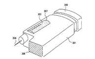
図25において、301は医療用投与器具本体、303は注射ボタン、304は注射針、306はこの従来の医療用投与器具を用いて注射液を投与する際、皮膚に当てる皮膚当て部、307は薬液カートリッジ、302は薬液カートリッジ307内の注射液である。 In FIG. 25, 301 is a medical administration device body, 303 is an injection button, 304 is an injection needle, 306 is a skin contact portion that is applied to the skin when administering an injection solution using this conventional medical administration device, and 307 is A
投与の際は、皮膚当て部306を皮膚に当てながら注射針304を皮膚に刺し、注射ボタン303を押し薬液カートリッジ307内の注射液302を押し出す。そして、投与量は注射ボタン303の押す量で加減しながら決定している。 At the time of administration, the
また、従来の医療用投与器具は、ほとんどの場合において、注射針は実際に注射液の投与を行う直前に投与器具本体に取り付けられ、注射液に混じって空気を注射するのを防ぐためにいわゆる空打ち(以下、エアー抜きとも称す)を行った後に、決められた量の薬液を人体に投与している。 Also, in most cases, conventional medical administration devices are so-called empty in order to prevent the injection needle from being mixed with the injection solution and injecting air immediately before the injection needle is actually administered. After hitting (hereinafter, also referred to as air venting), a predetermined amount of chemical solution is administered to the human body.
図24に外観図を示す従来の医療用投与器具では、薬液を投与するにあたり、投与器具本体に注射針の取り付けを忘れた状態のままでも、注射ボタンあるいは投与ボタンを押すことが可能である。このため、不用意に注射ボタンあるいは投与ボタンを押して不具合を招くことも起こり得る。 In the conventional medical administration device whose external view is shown in FIG. 24, it is possible to push the injection button or the administration button even when forgetting to attach the injection needle to the administration device body when administering the drug solution. For this reason, inadvertently pressing the injection button or the administration button may cause a problem.
また、従来の医療用投与器具は、医師が診断し、投与する注射液量、投与間隔の指示を出し、投与者はその指示に従い自分自身で薬液の自己投与を行うが、投与する注射液量、投与間隔の管理は、投与者自身に任されている。また、医師の診断は定期的に行われ、診断結果と、過去の投与された注射液量と、投与間隔から新しい投与する注射液量、投与間隔を決定し指示を出す。 In addition, conventional medical administration devices are diagnosed by a doctor and give instructions on the amount of injection solution to be administered and an administration interval, and the administrator himself administers the drug solution according to the instructions. The administration of the administration interval is left to the administration person himself. Further, the doctor makes a diagnosis periodically, and determines the diagnosis result, the amount of the injection solution administered in the past, the injection solution amount to be newly administered from the administration interval, and gives an instruction.
従来はこのような自己投与に使用される医療用投与器具は、図24あるいは図25に示すように機械式のものが多かったが、最近、電子的な装置を付加したものも考案されている。 Conventionally, many of the medical administration devices used for such self-administration have been mechanical, as shown in FIG. 24 or FIG. 25, but recently, devices with electronic devices have been devised. .
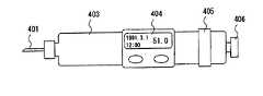
図26及び図27にその代表的な構造図を示す。また、図28に、マイクロプロセッサを中心としたブロック図を示す。図26は正面図を、図27は一部断面を表した上面図である。 FIG. 26 and FIG. 27 show typical structural views thereof. FIG. 28 is a block diagram centering on the microprocessor. 26 is a front view, and FIG. 27 is a top view showing a partial cross section.
図26において、403は注射器本体、401は注射針、404は表示部、405は注射液の投与量設定ダイヤル、406は注射ボタンである。 In FIG. 26, 403 is a syringe body, 401 is an injection needle, 404 is a display unit, 405 is a dose setting dial for an injection solution, and 406 is an injection button.
図27において、注射器本体403には注射液426の入ったカートリッジ407がセットされている。投与者は注射前に注射ボタン406を引き出す。注射ボタン406を引き出すと、注射ボタン406と共にスリーブ418とナット412も注射ボタン406と同方向にスライドする。 In FIG. 27, a
スリーブ418がスライドされることにより、スリーブ418のスプライン部416が投与量設定ダイヤル405のスプライン部417と結合される。スリーブ418とプランジャー408の結合部はスライド方向は固定されていないが、回転方向は固定されている。また、スリーブ418とナット412との結合部は、回転方向は固定されていないが、スライド方向は固定されている。 By sliding the
その結果、投与者が投与量設定ダイヤル405を回すことにより、スリーブ418が回り、これに伴ってプランジャー408も回り、ナット412の内周に設けられたネジと、プランジャー408の外周に設けられたネジにより、プランジャー408がスライドする。このプランジャー408がスライドする量により投与する注射液量が決まる。注射ボタン406が引き出されていなければ、スリーブ418と投与量設定ダイヤル405とが結合されず、投与量設定ダイヤル405を回転させても、プランジャー408は動かない。 As a result, when the user turns the
投与者は、投与量設定ダイヤル405を回転させ投与する注射液量を決定し、注射針401を注射する場所に刺し、注射ボタン406を押し込むことにより注射を完了させる。注射が完了した際には注射ボタン406、スリーブ418、ナット412が押し込まれた方向にスライドする。このとき、注射ボタン406、スリーブ418、ナット412がスライドしたことを検出するため、スリーブ418に突起420を設け、突起420によりオンまたはオフするスイッチ413を本体403に固定するように設けてある。 The administration person rotates the
注射ボタン406が引き出された状態では、スイッチ413はオンし、注射ボタン406が押し込まれた状態ではオフする。このスイッチ413の状態を見ることにより注射が完了したことを検出する。スイッチ413の状態により注射完了を判断する手段は図28のマイクロプロセッサ425等を用い、スイッチ413の導通状態を判定することで判断する。 The
なお、417は設定ダイヤル405のスプライン部、419a,419bは光センサ、414は液晶表示部、415は基板、421は回転板、421aは回転板スリットである。また、図28において、422はマイクロプロセッサ425のメモリ、423はカレンダ、424は時計、404は液晶表示部414との表示用インターフェイスである。
図29は、投与完了を検出する部分の拡大図である。また、投与する注射液量を設定する際には投与量設定ダイヤル405、スリーブ418が回転する。投与する注射液量は投与量設定ダイヤル405が回転することによるプランジャー408の移動量で決定される。したがって投与量設定ダイヤル405、スリーブ418が回転したこと及び回転量を検出することで、投与する注射液量を検出する方法が用いられている。なお、416はスリーブスプライン部、417は設定ダイヤルスプライン部である。 FIG. 29 is an enlarged view of a portion for detecting completion of administration. Further, when setting the amount of injection solution to be administered, the
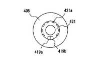
ここで、例えば、図30に示すように、投与量設定ダイヤル405と同時に回転する回転板421を設け、回転板421には図31のようにスリット421aが設けられ、光がスリット421aを横切る位置に2つの光センサー419a及び419bが設けられている。投与量設定ダイヤル405が回転すると、回転板421も回転し、回転板421に設けられたスリット421aが光センサ419a及び419bの光を透過又は遮断する。光センサ419a及び419bは光量に応じオン又はオフの信号を出力するため、光センサ419a及び419bの出力のオン又はオフにより回転及び回転量が検出できる。 Here, for example, as shown in FIG. 30, a
なお、2つの光センサ419a及び419bを用いるのは、投与量設定ダイヤル405の回転方向により、投与する注射液量が増える場合と減る場合があるためである。2つの光センサ419a及び419bの出力のオン又はオフの位相差により回転方向を判断し、光センサ419a及び419bの出力のオン及びオフの回数をカウントすることにより、投与する注射液量を検出する。前述のように、光センサ419a及び419bの出力の位相差により回転方向を判断し、光センサ419a及び419bの出力のオン及びオフの回数をカウントすることにより投与する注射液量を検出する手段は、図32に示すように、マイクロプロセッサ425等を用いている。 The reason for using the two
更に、投与完了時の時刻、日付の記録または表示等についてもマイクロプロセッサ425及びメモリ422を設けることにより行っている。また、光センサ419aと419bは光センサでなくスイッチ等を利用したものも考案されている。 Furthermore, the time and time of administration completion, date recording or display, etc. are performed by providing a
しかしながら、上記図24に示す従来の医療用投与器具においては、投与時に注射針204を皮膚に刺し、更に注射ボタン203を注射針204が皮膚に刺しこまれた方向と同方向に押しながら注射液202を投与するため、最初皮膚に注射針204が刺さった状態から更に注射針を深く皮膚に刺し込む形となり、投与時に患者の痛みが増してしまう。 However, in the conventional medical administration device shown in FIG. 24, the
また、図25に示す様に、医療用投与器具に皮膚当て部306が設けられている場合の投与においても、皮膚当て部306を皮膚に当てながら注射針304を皮膚に刺し、注射ボタン303を注射針304が皮膚に刺しこまれた方向と同方向に押しながら注射液302を投与するため、最初皮膚に注射針304が刺さった状態から更に注射針304を深く皮膚に刺し込む形となることは、前記の記述どおりである。なぜなら、皮膚当て部306が設けられていても、実際の皮膚には弾力があり、実際に注射器ボタン303を押せばその押した力の分だけ、注射針304は皮膚に深く刺さってしまうからである。 In addition, as shown in FIG. 25, even in the case where the
これを防ぐためには、投与中に、注射器ボタン303を押す側の腕を空中で固定するか、或いは何らかの方法で慎重に固定させて行う必要があるが、これは自分自身で薬液の投与を行う場合では、極めて困難である。 In order to prevent this, it is necessary to fix the arm on the side that pushes the
そして、投与中に注射針が皮膚に対して深く刺さると言うことは、患者の痛みが増すこととなり、肉体的、精神的にも苦痛を伴うだけでなく、場合によっては投与者(患者)の人体に多大な影響を及ぼし、生命に危険な状態を招きかねない、という問題があった。 And the fact that the needle penetrates deeply into the skin during administration increases the pain of the patient, which is not only physically and mentally painful, but also in some cases the patient (patient). There was a problem of having a great influence on the human body and inviting a dangerous state to life.
また、図24または図25に示す従来の医療用投与器具においては、注射針が必ずしも一定ではなく、注射針の種類によってその長さが異なるため、注射針の皮膚に入る量がばらつき、その量によっては、注射による失敗や痛みの負担などが大きく、投与者(患者)の人体に多大な影響を及ぼし、生命に危険な状態を招きかねない。 Further, in the conventional medical administration device shown in FIG. 24 or FIG. 25, the injection needle is not necessarily constant, and the length varies depending on the type of the injection needle. Depending on the condition, the failure due to the injection and the burden of pain are great, which may greatly affect the human body of the administration person (patient) and lead to a life-threatening state.
また、図24に示す従来の医療用投与器具においては、投与器具本体への注射針の取り付けを忘れた場合でも、注射ボタンあるいは投与ボタンを押すことが可能であるため、以下のような問題がある。 In addition, in the conventional medical administration device shown in FIG. 24, even when the injection needle is forgotten to be attached to the administration device body, the injection button or the administration button can be pressed, and thus the following problems are caused. is there.
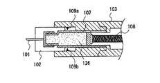
一つには、注射針を取り付けずに注射ボタンあるいは投与ボタンを押すと図33の漏れた薬液221aや逆流した薬液221bのように、薬液が注射ボタンあるいは投与ボタンと反対方向の先端部から漏れたり、また、注射ボタンあるいは投与ボタンの方向に薬液が逆流して漏れたり、更には、図34のように、薬液の入ったガラス管そのものが注射ボタンあるいは投与ボタンが押されることによって生じる圧力によってひび227が入ったり、破裂したりして割れてしまい、薬液が外に漏れてしまうなどの種々の問題が発生している。 For example, when the injection button or the administration button is pressed without attaching the injection needle, the drug solution leaks from the tip in the direction opposite to the injection button or the administration button, as in the case of the leaked
また、成長ホルモン製剤等のように、二種の薬液を混合させて投与したり、あるいは、薬剤と薬液とを溶解混合させて投与したりする場合においても、注射針を取り付けてから混合を行う必要があるため、注射針を付け忘れると、混合ができないばかりでなく、前記の記述のように、薬液の逆流、漏れ、あるいは薬液カートリッジのガラス管のひび割れ、破裂等が発生し問題となっている。前述の問題の多くは、特に、患者自身が自分で投与を行う場合に多く発生している。 In addition, in the case of administering two types of drug solutions, such as growth hormone preparations, or when dissolving and mixing a drug and a drug solution, mixing is performed after attaching an injection needle. If you forget to attach the injection needle, it is not only impossible to mix, but as mentioned above, chemical solution backflow, leakage, or cracking, rupture, etc. of the glass tube of the chemical solution cartridge will cause problems. Yes. Many of the aforementioned problems occur particularly when the patient himself administers himself.
また、図24ないし図27に示す従来の医療用投与器具においては、医師又は看護婦が投与する場合では事故の可能性は低いであろうが、患者自身が投与する場合においては、投与前に必ず行う注射器のエアー抜き操作を常に意識していないとこれを忘れる可能性がある。そして、エアー抜きを忘れた場合、人によっては人体に多大な影響を及ぼし、生命に危険な状態を招きかねない。 In the conventional medical administration device shown in FIG. 24 to FIG. 27, the possibility of an accident will be low when a doctor or a nurse administers. You may forget this if you are not always aware of the syringe bleed operation. And if you forget to vent the air, some people have a great influence on the human body, which can lead to life-threatening conditions.
また、図26または図27に示す従来の医療用投与器具においては、電子的な表示装置に、投与を行った注射液量を表示できるが、投与前に必ず行うエアー抜き操作時における注射液量、日付、時間までがメモリ422に記録されてしまうことになり、メモリ422の容量をいたずらに減らすだけでなく、エアー抜き操作時における注射液量をも本来の注射液量と同様に表示してしまうため、医師が投与者(患者)の診断結果と過去の投与履歴を確認して、その後の治療方法を決定する場合に、誤判断をしてしまう可能性がある。医師がこのような誤判断をしてしまうと、投与者(患者)の人体に多大な影響を及ぼし、生命に危険な状態を招きかねない。 In addition, in the conventional medical administration device shown in FIG. 26 or FIG. 27, the amount of injected liquid administered can be displayed on an electronic display device. The date and time will be recorded in the
本発明は、上記のような従来のものの問題点を解決するためになされたもので、安全かつ高い信頼性でもって薬液の注射を行うことが可能な医療用投与器具を提供することを目的としている。 The present invention has been made in order to solve the above-described problems of the prior art, and has an object to provide a medical administration device capable of injecting a drug solution with safety and high reliability. Yes.
即ち、本発明は、図26または図27に示すような電子的な装置を付加した従来の装置の問題点を解決するためになされたものであり、投与者が投与時に行うエアー抜き操作時の投与液量、日付、時刻については、メモリ422に記録できないようにし、信頼性のある投与履歴が残せる医療用投与器具を提供することを目的とするものである。 That is, the present invention has been made to solve the problems of the conventional apparatus to which the electronic apparatus as shown in FIG. 26 or FIG. 27 is added. An object of the present invention is to provide a medical administration device in which the administration liquid volume, date, and time cannot be recorded in the
上記目的を達成するために、本願の請求項1の発明に係る医療用投与器具は、投与器具本体と、投与器具本体の側面に設けられ、薬液カートリッジをセットする開閉式の扉と、薬液カートリッジの内部に収納されている注射液を、注射針を経由して投与するための注射ボタンと、投与器具本体の内部に配置され、注射ボタンと連結されて、注射ボタンが押された時に、注射液を押し出すプランジャーと、注射ボタンの押圧力を、プランジャーに伝達する押圧力伝達部と、を備え、扉の開閉する角度、注射ボタンを押圧する方向、及び、押圧力伝達部の伝達する方向は、注射針を刺す方向に対して、それぞれ平行でない角度に配置されるようにしたものである。 In order to achieve the above object, a medical administration device according to
これにより、注射ボタンを押したときの力が、最初、注射針を皮膚に刺したときより更に深く皮膚に刺し込まれるように伝わることがなく、投与患者の肉体的、精神的苦痛を増すことがない。 As a result, the force when the injection button is pressed is not transmitted to the skin deeper than when the needle is first stabbed into the skin, increasing the physical and mental pain of the administered patient. There is no.
また、本願の請求の範囲第2項の発明に係る医療用投与器具は、請求項1に記載の医療用投与器具において、前記押圧力伝達部は、前記注射ボタンの押圧方向と同方向に延在するラックと、該ラックの長手方向のー側面に形成された歯形と噛合する第1の歯車と、
該第1の歯車と噛合する第2の歯車と、前記ラックの延在する方向と直交する方向のー側面に前記第2の歯車と噛合する歯形を有する可動ピースとを有し、前記注射ボタンの押圧操作により前記可動ピースは前記薬液カートリッジのプランジャーを押圧するようにしたものである。The medical administration device according to
A second gear that meshes with the first gear, and a movable piece having a tooth shape that meshes with the second gear on a side surface in a direction perpendicular to the direction in which the rack extends, and the injection button The movable piece is configured to press the plunger of the chemical cartridge by the pressing operation.
これにより、注射ボタンを押したときの力が、最初、注射針を皮膚に刺したときより更に深く皮膚に刺し込まれるように伝わることがなく、投与患者の肉体的、精神的苦痛を増すことがない。 As a result, the force when the injection button is pressed is not transmitted to the skin deeper than when the needle is first stabbed into the skin, increasing the physical and mental pain of the administered patient. There is no.
さらに、本願の請求の範囲第3項の発明に係る医療用投与器具は、請求項1に記載の医療用投与器具において、投与する注射液量が設定できる注射液量設定部を備えるようにしたものである。 Furthermore, the medical administration device according to the invention of
これにより、投与時は、注射ボタンを押すだけで、投与量目盛を見ることがなく、投与患者の負担が軽減される。 Thereby, at the time of administration, the burden on the administration patient can be reduced by simply pressing the injection button without looking at the dose scale.
また、本願の請求の範囲第4項の発明に係る医療用投与器具は、請求項3に記載の医療用投与器具において、前記注射液量設定部は、前記プランジャーと一体化され前記可動ピースを貫通し、且つ、該ピースと噛合するスリーブと、該スリーブの前記プランジャーとは反対側に取り付けられ、投与者が回転する方向を変えることで前記可動ピースを前記薬液カートリッジの内部で前,後に移動させる投与量調節つまみとを有するようにしたものである。 The medical administration device according to claim 4 of the present application is the medical administration device according to
これにより、投与量調節つまみを操作することで事前に投与量を設定しておくことで、実際の投与時には、注射ボタンを押すだけで、投与量目盛を見ることがなく、投与患者の負担が軽減される。 In this way, by setting the dose in advance by operating the dose adjustment knob, at the time of actual administration, simply pressing the injection button does not look at the dose scale, and the burden on the administration patient is reduced. It is reduced.
また、本願の請求の範囲第5項の発明に係る医療用投与器具は、請求項1に記載の医療用投与器具において、投与後に、注射ボタンを押した指を離すと注射ボタンを元の位置に戻す注射ボタン復帰部を備えるようにしたものである。 Moreover, the medical administration device according to the invention of claim 5 of the present application is the medical administration device according to
これにより、投与後に、投与患者が再度投与を行うために注射ボタンを戻す必要が無く、投与患者の負担を軽減する。 Thereby, it is not necessary to return the injection button for the administration patient to administer again after administration, thereby reducing the burden on the administration patient.
さらに、本願の請求の範囲第6項の発明に係る医療用投与器具は、請求項5に記載の医療用投与器具において、前記注射ボタン復帰部は、前記ラックの前記注射ボタンとは反対側の端面と医療用投与器具本体の内側面との聞に介在されたばねからなるものとしたものである。 Furthermore, the medical administration device according to the invention of claim 6 of the present application is the medical administration device according to claim 5, wherein the injection button return portion is opposite to the injection button of the rack. It consists of a spring interposed between the end surface and the inner surface of the medical administration device main body.
これにより、簡単な構成を付加するだけで、投与後に、投与患者が再度投与を行うために注射ボタンを戻す必要が無く、投与患者の負担を軽減できる。 Thereby, it is not necessary to return the injection button for the administration patient to administer again after administration by simply adding a simple configuration, and the burden on the administration patient can be reduced.
(実施の形態1)
この実施の形態1は、注射ボタンを押す方向が、注射針が皮膚に刺しこまれた方向と異なる方向となるように装置を構成することで、注射ボタンの操作時にさらに注射針を深く刺し込むことがないようにしたものである。(Embodiment 1)
In the first embodiment, the device is configured such that the direction in which the injection button is pressed is different from the direction in which the injection needle is inserted into the skin, so that the injection needle is further inserted deeply when the injection button is operated. It is intended to prevent it from happening.
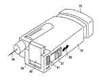
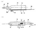
以下では、本発明の実施の形態1について、図1ないし図3を用いて説明する。図1は、本発明の実施の形態1に係る医療用投与器具の外観を示す斜視図、図2は本発明の実施の形態1に係る医療用投与器具の一部を破断して内部構造を示す斜視図、図3は本発明の実施の形態1に係る医療用投与器具を実際に手で握った状態を示す。 Hereinafter,
図1において、1は医療用投与器具本体、2は注射液、3は注射ボタン、4は注射針、6は皮膚当て部、7は薬液カートリッジ、8は液晶表示部、9は投与量調整つまみである。また、注射ボタン3は、注射針4の延びる方向に対してほぼ垂直方向にこれを押すように構成されている。この注射ボタン3を押し込む方向は、注射針4の延びる方向と平行でなければ、垂直方向に限るものではなく、患者の身体への痛みを和らげる方向であれば、他の角度でもかまわない。 In FIG. 1, 1 is a medical administration device body, 2 is an injection solution, 3 is an injection button, 4 is an injection needle, 6 is a skin contact portion, 7 is a chemical cartridge, 8 is a liquid crystal display portion, and 9 is a dose adjustment knob. It is. The
注射液の投与手順として、まず、薬液カートリッジ7を医療用投与器具本体1にセットし、注射針4を取り付け、投与したい注射液2の量を設定するため、投与量調整つまみ9を図中の矢印で示すように右方向あるいは左方向に回転させる。次に、注射針を真上に向け、注射ボタン3を注射針4の先から注射液2が出るまで押してエアー抜きを行う。このエアー抜き完了後、図3のように医療用投与器具を手19で握り、皮膚当て部6を投与患部の皮膚に当てながら注射針4を皮膚に刺し、注射ボタン3を人差し指18で図3の矢印方向に押しながら投与を行う。 As a procedure for administering the injection solution, first, the drug solution cartridge 7 is set in the medical
次に、図2を用いて、注射液量の設定方法及び前記記述の注射ボタン3を押したときに注射液2が注射針4から出てくる仕組みについて説明する。 Next, with reference to FIG. 2, a method for setting the amount of injection solution and the mechanism by which the
まず、注射液量の設定方法から説明する。投与量調整つまみ9とスリーブ10とは、回転方向は固定されているがスライド方向は固定されていない。また、スリーブ10と可動ピース14内を経由しているプランジャー15とは一体部材で構成されている。可動ピース14の内側には、スリーブ10と可動ピース14内で係合できる内ネジ16が切ってあり、スリーブ10の可動ピース14内に入っている部分については、可動ピース14内で係合できる外ネジ16が切ってある。 First, the method for setting the injection volume will be described. The dose adjustment knob 9 and the
また、プランジャー15は、薬液カートリッジ7内のプランジャー20とは別部材で構成されており、プランジャー20とは離間している。プランジャー20の先端には、薬液カートリッジ7内で注射液2を押し出せるようにゴム材で形成され、プランジャー20と固定されたプランジャー21が設けられている。また、可動ピース14のスライド量はばね17による規制で常に一定となるように構成されている。 Further, the plunger 15 is configured as a separate member from the
今、投与量調整つまみ9を投与量が増加する方向に回転させると、プランジャー15は可動ピース14から注射針の方向に長く出てくる。すると、プランジャー15とこれとは別体のプランジャー20との離間距離が短くなる。また、プランジャー20は、プランジャー15から押されない限り動かない。そして、注射ボタン3を押したときの可動ピース14のスライド量は常に一定であるため、プランジャー15のプランジャー20を押す距離が投与時の注射液量となる。つまり、投与する注射液量に関係なく、投与時の注射ボタンのストロークは常に同じであり、プランジャー15の可動ピース14からのスライド量(でしろ)で投与量が決定される。 Now, when the dose adjustment knob 9 is rotated in the direction in which the dose increases, the plunger 15 comes out from the
次に、注射ボタン3を押したとき、注射液2が注射針4から出てくる仕組みについて説明する。図2において、注射ボタン3を矢印方向に押すと、これと一体部材で構成されたラック11も矢印方向にスライドする。ラック11の注射ボタン3と反対側の端面には、ばね(注射ボタン復帰部)17が、注射ボタン3を押したとき圧縮され、注射ボタン3を押すのをやめると弾性により復帰するような形で設けられている。このため、注射ボタン3を押すのをやめると、ばね17の復帰力により、注射ボタン3は元の位置に戻る。 Next, a mechanism in which the
ラック11の側面には、歯型11aが設けられており、この歯型11aと噛み合うように歯車(第1の歯車)12が、また、歯車12と噛み合うように歯車13(第2の歯車)が設けられている。また、可動ピース14の側面には歯車13と噛み合うように歯型が設けられている。これらラック11、歯車12、歯車13は注射ボタン3の押圧力を注射針4の延びる方向と異なる角度でプランジャー15に伝達する押圧力伝達部を構成する。 A
注射ボタン3を押すと、ラック11がスライドし、歯車12が反時計方向に回転し、歯車13は時計方向に回転する。すると、可動ピース14は、プランジャー15と一体となって、プランジャー20及びプランジャー21を押す方向にスライドする。すると、プランジャー21は薬液カートリッジ7内の注射液2を圧縮する方向にスライドし、圧縮された注射液2は、注射針4の先端から押し出される。 When the
本実施の形態1に示す医療用投与器具は、前記の記述のように、注射ボタン3を人差し指18で図3の矢印方向に押したときの力が、注射針4を、最初皮膚に刺したときより更に深く皮膚に刺し込ませるようには伝わらない構造となっている。 In the medical administration device shown in the first embodiment, as described above, the force when the
このため、本実施の形態1によれば、薬液の投与時に、注射ボタンを押す力が、当初注射針を皮膚に刺したときよりさらに深く皮膚に刺さるように伝わることを防止し、安定した状態で薬液を投与することが可能となる。
(実施の形態2)
この実施の形態2は、薬液を投与する際に投与者の皮膚に当たる皮膚当て部を注射針の長手方向にスライドさせて固定可能とすることで、注射針の種類,大きさに関係なく針先が皮膚に刺さる量が一定となるように調節することが可能となり、薬液を投与する際の痛みを軽減できるようにしたものである。For this reason, according to the first embodiment, at the time of administration of the drug solution, the force of pushing the injection button is prevented from being transmitted to penetrate the skin deeper than when the initial injection needle is inserted into the skin, and is in a stable state. It becomes possible to administer a drug solution.
(Embodiment 2)
In the second embodiment, when the drug solution is administered, the skin contact portion that contacts the skin of the user can be fixed by sliding in the longitudinal direction of the injection needle, so that the needle tip is independent of the type and size of the injection needle. It is possible to adjust so that the amount pierced into the skin is constant, and to reduce the pain when administering the drug solution.
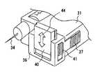
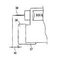
以下では、本発明の実施の形態2について、図4ないし図7を用いて説明する。図4は、本発明の形態2に係る医療用投与器具の外観を示す斜視図、図5は本発明の形態2に係る医療用投与器具の一部断面図、図6は本発明の形態2に係る医療用投与器具の斜視詳細図、図7は本発明の医療用投与器具の注射針と皮膚当て部との関係詳細図を示す。 Hereinafter,
図4において、31は医療用投与器具本体、32は注射液、33は注射ボタン、34は注射針、36は皮膚に当てる皮膚当て部、37は皮膚当て部分調整ボタン、40は皮膚当て幅調整ピース(皮膚当て面積可変部、皮膚当て幅調節部)、41は皮膚当て幅調整ボタンである。皮膚当て部分調整ボタン37は皮膚当て部36と一体化されており、矢印43のいずれの方向にもスライドできるように構成されている。 In FIG. 4, 31 is a medical administration device body, 32 is an injection solution, 33 is an injection button, 34 is an injection needle, 36 is a skin contact portion to be applied to the skin, 37 is a skin contact portion adjustment button, and 40 is a skin contact width adjustment. A piece (skin application area variable part, skin application width adjustment part), 41 is a skin application width adjustment button. The skin contact
図5において、皮膚当て部36は皮膚当て部分調整ボタン(皮膚当て位置可変部)37と一体となっており、皮膚当て部36、皮膚当て部分調整ボタン37は所望の位置でストップし固定できるように、皮膚当て部分調整ボタン37にダボ(凸形状)38を、医療用投与器具本体31の側面に凹形状39を、嵌合固定部として、それぞれ設けている。 In FIG. 5, the
従って、図4に示すように、注射針34に対し、皮膚当て部36、皮膚当て部分調整ボタン37は矢印43方向の所望の凹形状の位置に可変、固定が可能となり、図7のように注射針34と皮膚当て部36とは所望の段階での寸法関係42とすることができる。 Therefore, as shown in FIG. 4, the
また、投与の際、毎回同じ種類の注射針34などを使用する場合については、注射針34に対する皮膚当て部36の寸法関係42を、その最適位置に可変したうえでこれを固定すれば、毎回同じ状態での投与が可能となり、投与者(患者)の皮膚に入る注射針34の長さが一定となるため、信頼性の良い投与が可能となる。 Further, when the same type of
図6において、皮膚当て幅調整ピース40は皮膚当て幅調整ボタン41と一体化されており、矢印方向44、即ち図中の下方向へスライドし、皮膚当て部36をより広くすることにより、投与の際、投与者が皮膚当て部36を皮膚に当てたとき、よりホールド感の良い安定感のある状態での投与が可能となる。 In FIG. 6, the skin pad
このため、本実施の形態2によれば、注射針の種類、大きさを問わず皮膚に注射針の入る長さを一定にし、皮膚当て部分の位置が可変できるようにし、さらに皮膚当て面積が増加可変できるようにしたので、注射針の種類によってその長さが異なっても注射針の皮膚に入る量がばらつくことがなく、投与状態を安定化することができ、信頼性の高い医療用投与器具を提供することが可能となる。 For this reason, according to the second embodiment, the length that the injection needle enters the skin is made constant regardless of the type and size of the injection needle, the position of the skin contact portion can be varied, and the skin contact area is further increased. Since it can be increased, the amount that enters the skin of the injection needle does not vary even if the length varies depending on the type of injection needle, the administration state can be stabilized, and highly reliable medical administration An instrument can be provided.
なお、このダボと凹形状に代えて任意の位置で皮膚当て部36を固定できるようにすることで、皮膚当て部36の位置を無段階で調節できるようにしてもよい。 Note that the position of the
また、実施の形態1と同様の内部構造とすることにより、注射ボタンの押圧方向を注射針204が皮膚に刺しこまれた方向と異なるようにすることで、注射の際の痛みを軽減するようにしてもよい。
(実施の形態3)
この実施の形態3は、注射針が投与器具本体に取り付けられていないときには、注射ボタンあるいは投与ボタンを押すことができないようにし、また、混合型薬物投与の場合においても、注射針が投与器具本体に取り付けられていないときには、薬物の混合ができず、投与器具本体内に収納できないようにすることで、薬液の漏れ、逆流、また、薬液の入ったガラス管のひび割れ、破裂等を防ぐようにしたものである。Further, by adopting the same internal structure as in the first embodiment, the pressing direction of the injection button is made different from the direction in which the
(Embodiment 3)
This
以下では、本発明の実施の形態3について図8ないし図15を用いて説明する。図8は、本発明の実施の形態3に係る医療用投与器具の一部を切り欠いて内部構造を示す斜視図である。図9は、本実施の形態3における医療用投与器具の注射針を取り付けたときの動作原理をわかりやすく説明するための斜視図であり、図10は、同じく、注射針を取り付けないときの動作原理をわかりやすく説明するための斜視図である。図11は、本実施の形態3における医療用投与器具の薬液カートリッジの取り付け動作を説明するため、一部を切り欠いて示す断面図である。図12は、本実施の形態3における医療用投与器具の、注射針を取り付けないときの検知機構と注射ボタンとの位置関係図である。図13は、本実施の形態3における医療用投与器具の、注射針を取り付けたときの検知機構と注射ボタンとの位置関係図である。図14は、本実施の形態3における医療用投与器具の、注射針を取り付けないときの検知機構と固定、解除機構との位置関係図である。図15は、本発明の実施の形態3における医療用投与器具の、注射針を取り付けたときの検知機構と固定、解除機構との位置関係図を示す。 Hereinafter, a third embodiment of the present invention will be described with reference to FIGS. FIG. 8 is a perspective view showing the internal structure of the medical administration device according to
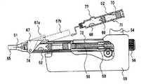
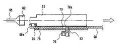
図8において、注射の仕組みを簡単に説明する。投与器具66本体内に、薬液カートリッジ52がセットされており、薬液カートリッジ52には、使い捨ての注射針51が取り付けられている。人体に投与する場合、投与量設定つまみ56を投与したい量に調節する。プランジャー55は、投与量設定つまみ56と回転方向に対しては固定されているが、スライド方向に対しては固定されていないため、投与量設定つまみ56を回転させると、注射針と平行な方向に伸縮可能となっている。今、投与量を増やす方向に設定したとき、プランジャー55は、注射針と同方向にその先端方向に向かって移動する。 In FIG. 8, the mechanism of injection will be briefly described. A
次に投与ボタン54を押すと、注射ボタン一体型駆動レバー57が注射ボタンの押された方向と同一方向に動作する。注射ボタン一体型駆動レバー(注射ボタン、ラック)57の側面の一部は、歯車(第1の歯車)60と噛合う歯車(ラック)となっている。また、歯車(第2の歯車)59は、歯車60と噛合うように、また、プランジャー55の先端部の歯車(ラック)とも噛合うようになっている。プランジャー55の先端には、薬液押し出しプランジャー53があり、薬液カートリッジ52内の薬液と接触している。これら注射ボタン一体型駆動レバー57、歯車60,歯車59はプランジャー55の駆動部を構成する。 Next, when the
いま、注射ボタン54を図8の矢印の方向に押すと、注射ボタン一体型駆動レバー57が歯車60を時計方向に回転させる。歯車60の回転により、歯車59は反時計方向に回転しながら、プランジャー55を注射針51の長手方向に、即ちプランジャー55を図8中の左側に向けて移動させる。すると、プランジャー55の先端部に設けられた薬液押し出しプランジャー53が薬液カートリッジ52内の薬液を注射針51から押し出し投与ができる。 Now, when the
次に、図9において、イジェクトレバー58の先端部(L字状先端部)58aは、注射針51の樹脂部82と薬液カートリッジ52との間にはさまれた状態にある。このとき、注射ボタン54を矢印方向に押すと、注射ボタン一体型駆動レバー57はイジェクトレバー58の噛合い部分61の中を自由に移動できる状態になっている。これらイジェクトレバー58および注射ボタン一体型駆動レバー57は注射ボタンを押すことによる投与動作を抑止する投与動作抑止部を構成する。また、イジェクトレバー58の先端部(検知部材)58aはイジェクトレバー58の本体と一体のものであり、樹脂部82と一体に形成された注射針51が取り付けられているときは、ばね63によって常に注射針51の方向に応力が加わっている。このばね(ばね部材)63とイジェクトレバー58とは注射針装着検知部を構成している。 Next, in FIG. 9, the distal end portion (L-shaped distal end portion) 58 a of the
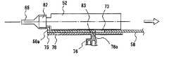
次に図10のように、注射針51を薬液カートリッジ52から取り外すと、イジェクトレバー58の部分が、ばね63の応力によって注射針51の方向、即ち図9中の左側に移動する。すると、イジェクトレバー58の噛合い部分61は、注射ボタン一体型駆動レバー57との噛合い部分62から外れ、注射ボタン54を矢印方向に押したとき、噛合い部分62がすぐにイジェクトレバー58の側面に当たり、自由に移動できなくなる。つまり、注射針51を取り外すと、注射ボタン54を完全に押し込むことができなくなる。このように、本実施の形態3では、イジェクトレバー58の先端部58aの部分において注射針が取り付けられているか、いないかを検知させている。 Next, as shown in FIG. 10, when the
次に、薬液カートリッジ52を投与器具本体66にセットし、投与器具本体66内に収納する方法を薬剤と薬液を溶解混合させる薬液カートリッジを例にあげ、図11を用いて説明する。 Next, a method of setting the
図11において、薬液カートリッジ押さえ蓋(開閉式の扉)67を図の破線部の状態まで上方向に上げ、薬液カートリッジ52を図の矢印の方向に挿入する。挿入後、薬液カートリッジ押さえ蓋67を下方向に下げ閉じる。次に、注射針51を、注射針キャップ65を被せた状態のまま、薬液カートリッジ52の先端ねじ部にねじ込む。 In FIG. 11, the chemical cartridge holding lid (openable door) 67 is raised upward to the state of the broken line in the figure, and the
次に、突起部67aを持ち、投与量設定つまみ56の方向にスライドさせる。すると、先ず薬液カートリッジ52内部の後部ゴム部70が投与器具本体66内の溶解ピース72に当たる。更に、スライドさせていくと、溶解ピース72が後部ゴム部70を押すことになり、これにより、後半室に充填された薬液71が分離用ゴム69を、薬剤68を収納している前半室の方向に移動させる。 Next, the
そして、分離用ゴム69が注入溝77まで移動してくると、薬液71が注入溝(大径部)77を通り、薬剤68に流れ込む。更に、突起部67aをもって投与量設定つまみ56の方向にスライドさせていくと、注入溝77から薬液71が全て薬剤68の部屋に流れ込み、結果的に薬剤68と薬液71が混合される。そして、突起部67aをもって更に前記投与量設定つまみ56の方向にスライドさせていくと、後部ゴム部70が分離用ゴム69に当たった時点で、スライドできなくなり、固定される構造となっている。この固定される構造については、図15の説明のところで記述する。そして、この状態で、薬液カートリッジ52が投与器具本体66内に収納されたことになる。 When the
次に、図12及び図13に、注射針が取り付けられているときと、取り付けられていないときの検知機構と注射ボタン一体型レバー57との関係を詳しく示す。図12は注射針が取り付けられていないときを、また、図13は、注射針が取り付けられたときの状態を、それぞれ示している。なお、図12ないし図15の説明の中での「注射針」とは、キャップ65が被さった状態での注射針51を指している。 Next, FIGS. 12 and 13 show in detail the relationship between the detection mechanism and the injection button integrated
図12(a)において、薬液カートリッジ52はスライドピース75の先端に位置した状態で留まっている。そして、スライドピース75の上には、イジェクトレバー58が位置し、スライドピース75の上を注射針取り付け方向と平行に自由に移動可能に構成されている。 In FIG. 12A, the
また、図12(b)は、図12(a)を下側から見た図であり、スライドピース75には、イジェクトノブ76が入る大きさのスリット78とスリット83とが設けられている。また、イジェクトレバー58にも、スリット83と同じ位置にスリット73を設けている。 FIG. 12B is a view of FIG. 12A as viewed from below, and the
また、スライドピース75とイジェクトレバー58の中央部には、それぞれこれらの重なった部分に、同一幅のスリット81が設けられ、更に、前記スリット81の中には、スライドピース75とイジェクトレバー58の重なった厚み寸法の中で収まるようなばね63がスライドピース75と平行に設けられている。しかも、ばね63は、前記スリット81の内側において、スライドピース75から突出した突起79とイジェクトレバー58から突出した突起80との間で係止されている。また、このときイジェクトレバー58の噛合い部61の位置は、注射ボタン一体型駆動レバー57が噛合い部61の中を自由に動くことができない位置関係となっている。つまり、注射ボタンを押すことができない状態である。 In addition, a
次に、図13において、注射針を薬液カートリッジ52に取り付けたとき、イジェクトレバー58の先端58aは、スライドピース75の先端位置まで押される。すると、スリット81の中のばね63は、図12(b)の状態から、圧縮された形でその状態を保つ。一方、イジェクトレバー58の噛合い部61の部分は、注射ボタン一体型レバー57が自由に移動できる位置関係となる。つまり、注射ボタンを押すことが可能な状態である。 Next, in FIG. 13, when the injection needle is attached to the
次に、注射針を薬液カートリッジ52へ取り付けないときと、取り付けた時に薬液カートリッジ52が投与器具本体66内へ収納することができない原理と、できる原理について図14と図15を用いて説明する。 Next, the principle when the injection needle is not attached to the
図14において、注射針が薬液カートリッジ52に取り付けられていないとき、イジェクトレバー58の先端部58aは、スライドピース75の先端よりも、更に注射針の方に向かって飛び出している。このとき、図示しないばねにより上方向に押圧付勢されているイジェクトノブ76は、イジェクトレバー58上のスリット(開口部)73とスライドピース75上のスリット(開口部)83との二つのスリットを貫通した状態で、スライドピース75を、注射針の方向にも、また、これと逆方向にも動くことができないように係止させている。尚、イジェクトノブ76は、スライドピース75及びイジェクトレバー58に対して、垂直方向に配置され、且つ、図14、図15に対して、常に上方向にバネで押し上げられた状態となっている。 In FIG. 14, when the injection needle is not attached to the
次に、図15において、注射針が薬液カートリッジ52に取り付けられると、イジェクトレバー58の先端部58aは、スライドピース75の先端と同じ位置になる。注射針を薬液カートリッジ52にねじ込んで(取り付けて)いく過程で、イジェクトレバー58のスリット73の内側がイジェクトノブ76の傾斜部分76aを矢印方向に押していくため、イジェクトノブ76は、徐々に下方向に押し下げられていく。更に、注射針をねじ込んでいくと、イジェクトレバー58上のスリット73は、イジェクトノブ76の傾斜部76aを更に押し下げる方向に動く。そして、注射針を完全に薬液カートリッジ52に取り付けたとき、イジェクトレバー58上のスリット73はイジェクトノブ76の先端を押し下げて通過しており、イジェクトノブ76はスライドピース75のスリット83の中に位置しており、スライドピース75を矢印と逆方向に係止した形となっている。 Next, in FIG. 15, when the injection needle is attached to the
この状態から、薬液カートリッジ52を投与器具本体66内に収納させようとするには、スライドピース75上に配置されている薬液カートリッジ52をスライドピース75と共に矢印方向にスライドさせながら移動させる。 From this state, in order to store the
実際には図11のところで説明したように、薬液カートリッジ押さえ蓋67の中に、セットした形で移動させる形となるが、ここでは原理のみを説明する。 Actually, as described with reference to FIG. 11, the
いま、スライドピース75上の薬液カートリッジ52をスライドピース75と共に矢印方向、即ち図14の右方向に移動させていくと、イジェクトノブ76の傾斜部76aにスリット83が当たる。この時点から更に矢印方向に移動させていくと、イジェクトノブ76はスライドピース75によって下側に押し下げられ、更に、スライドピース75が矢印方向に移動していくと、スライドピース75のスリット78の中にイジェクトノブ76の先端が嵌合し、それと同時に、スライドピース75をイジェクトノブ76の先端がその位置で係止させ、矢印と反対方向に移動できないようにする。 Now, when the
この状態を表したのが、図13(a)であり、この状態を解除するためには、イジェクトノブ76と一体となっているスライドつまみが、投与器具本体66の外部につまみとして出ているので、前記スライドつまみを強制的に、指で軽く下方向に押し下げることにより、解除操作が可能となるようにしている。 FIG. 13A shows this state, and in order to cancel this state, a slide knob integrated with the
また、これは、例えば、投与器具本体内において、二種の薬液を混合あるいは、図11のところで説明したように、薬剤と薬液を溶解混合させる場合、注射針を取り付けないと投与器具本体内に収納することができないため、混合させることができないことになる。 In addition, this is because, for example, in the case of mixing two kinds of drug solutions in the administration device main body, or when dissolving and mixing the drug and the drug solution as described in FIG. Since it cannot be stored, it cannot be mixed.
このように、本実施の形態3によれば、注射針が投与器具に取り付けられていない時は、注射ボタンあるいは投与ボタンを押すことができず、薬液を押し出すプランジャーが動作しない構成としたので、また、混合型薬物投与の投与器具の場合は、注射針が投与器具に取り付けられていない時は混合できない構成としたので、投与器具本体に注射針が取り付けられていない場合は誤って注射ボタンあるいは投与ボタンを押そうとしてもこれを押すことができず、誤操作による薬液漏れや薬液ガラス管等の破壊を防ぐことが可能となる。
(実施の形態4)
この実施の形態4は、電子的な装置を付加した医療用投与器具において、注射を行う際にエアー抜きを行うように注意を促す警告表示を行うようにしたものである。Thus, according to the third embodiment, when the injection needle is not attached to the administration device, the injection button or the administration button cannot be pushed, and the plunger for pushing out the drug solution does not operate. In addition, in the case of an administration device for mixed drug administration, since it is configured such that mixing is not possible when the injection needle is not attached to the administration device, if the injection needle is not attached to the administration device body, the injection button is erroneously set Alternatively, even if an administration button is pressed, it cannot be pressed, and it is possible to prevent a chemical solution leak or a chemical solution glass tube from being broken due to an erroneous operation.
(Embodiment 4)
In the fourth embodiment, in a medical administration device to which an electronic device is added, a warning display for prompting attention to perform air bleeding when an injection is performed is performed.
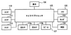
以下、本発明の実施の形態4について図16ないし図18を用いて説明する。図16は、本発明の実施の形態4に係る医療用投与器具の注射針取り付け前の外観を示す斜視図、図17は実施の形態4の医療用投与器具の一部断面図、図18は、マイクロプロセッサ25を中心としたブロック図である。 The fourth embodiment of the present invention will be described below with reference to FIGS. 16 is a perspective view showing an external appearance of the medical administration device according to Embodiment 4 of the present invention before the injection needle is attached, FIG. 17 is a partial sectional view of the medical administration device of Embodiment 4, and FIG. 2 is a block diagram centering on a microprocessor 25. FIG.
図16において、102は本体用キャップ、103は医療用投与器具本体、104は表示部、105は投与量設定ダイヤル、106は注射ボタン、127はスピーカである。 In FIG. 16, 102 is a main body cap, 103 is a medical administration device main body, 104 is a display unit, 105 is a dose setting dial, 106 is an injection button, and 127 is a speaker.
まず、医療用投与器具の使用が初回であるとして説明する。図16、図17において、本体用キャップ102を医療用投与器具本体103から外すと、医療用投与器具本体103に設けられたスイッチ(第1のスイッチ)110がオンからオフになる。このとき、表示部104に表示される全ての機能表示が全点灯し、何秒か後にカレンダ、時間及び投与量のみが表示される。 First, it is assumed that the medical administration device is used for the first time. 16 and 17, when the
また、図17において、医療用投与器具本体103の螺合部109a及び109bの部分はそれぞれネジにて係合されている。前記螺合部109a、109bの部分をネジが緩む方向に回転させ、一つの医療用投与器具本体103の状態から二つの螺合体103a、103bに分離させる。分離後、螺合体103aの方に薬液カートリッジをセットし、再び螺合体103aと103bを螺合部109aと109bの部分で係合させ、螺合体103aと103bが固定される方向に回転させ元の医療用投与器具103の形とする。すると、医療用投与器具103の内側に設けられたカートリッジ検出用スイッチ(第2のスイッチ)111がオフからオンになる。 In FIG. 17, the screwing
この状態になったとき表示部104には、「エアー抜き」の文字が現れ点滅を始める。前記点滅表示と同期してスピーカー127からは「エアー抜きをしてください」の音声が流れる。投与者は注射針101を取り付け、注射針101を上に向け、注射ボタン106を下向きにした状態で注射針101から薬液126が出るまで注射ボタン106を押す。すると、スイッチ113(従来の技術で記載した図32のスイッチ413に相当)が一度オンし再びオフする。このスイッチ113の状態をエアー抜きが終了したことの判定にも利用し、マイクロプロセッサ(エアー抜き表示信号発生部)125でエアー抜き終了と判断させる。 When this state is reached, the characters “Bleeding air” appear on the
尚、前記記載の「エアー抜き」文字の点滅と音声でのアナウンスは、スイッチ113の状態をマイクロプロセッサ125がエアー抜き終了と判断するまで継続される。また、前記スイッチ110及びスイッチ111の状態の判断及び表示部104への表示命令、音声アナウンスの命令は、図18のマイクロプロセッサ(エアー抜き音声信号発生部)125によって行われる。即ち、これらマイクロプロセッサ125、表示部104、スピーカ127はエアー抜き告知部を構成している。また、この図18において、123は日付情報を発生するカレンダ、124は時刻情報を発生する時計である。 It should be noted that the flashing and voice announcement of the “air bleeding” character described above continues until the
次に、前記薬液カートリッジ107がすでに医療用投与器具103にセットされた状態、つまり2回目以降の投与の場合について説明する。本体用キャップ102を医療用投与器具103から取り外すと、医療用投与器具本体103に設けられたスイッチ110がオンからオフになる。このとき、表示部104に表示される全ての機能表示が全点灯し、何秒か後にカレンダ、時間及び投与量のみが表示される。 Next, a state in which the
次に、表示部104には「エアー抜き」文字が点滅表示され、それと同期してスピーカー127からは「エアー抜きをしてください」の音声が流れる。投与者は注射針101を取り付け、注射針101を上向きに、注射ボタン106を下向きにした状態で注射針101から薬液126が出るまで注射ボタン106を押す。すると、前記初回の使用の場合同様、マイクロプロセッサ125がスイッチ113の状態を見て、エアー抜き終了と判断すると「エアー抜き」文字の表示は消え、更に音声での「エアー抜きをしてください」のアナウンスも停止する。 Next, the
尚、注射が完了したことを検出する手段、投与された注射液量を検出する手段、投与された注射液量を記録する手段、注射が完了したことを検出し、投与された注射液量を検出すると同時に検出された注射液量、日付、時刻をも同時に記録し、表示する手段については、従来の技術で記述したとおりである。 It should be noted that means for detecting the completion of injection, means for detecting the amount of injected liquid administered, means for recording the amount of injected liquid injected, detecting completion of injection, and determining the amount of injected liquid injected The means for simultaneously recording and displaying the injection volume, date, and time detected simultaneously with the detection are as described in the prior art.
なお、上述の説明でエアー抜きを促す表示は、文字以外に記号や図形を用いても良い。また、表示と音声とを何れか一方にて、投与者にエアー抜きの操作を行うように促してもよい。 In the above description, a sign or a figure may be used for the display for prompting air bleeding in addition to the characters. In addition, the user may be urged to perform an air bleeding operation by either one of display and sound.
このように、本実施の形態4によれば、注射針が取り付けられる医療用投与器具本体の注射針の取り付け部分を覆うように取り付けられた本体キャップを外したときに、「エアー抜き」の文字を表示部に表示するようにしたので、薬液の投与者に投与前のエアー抜き操作を意識させることができ、「エアー抜き」の操作を促すことができる。
(実施の形態5)
この実施の形態5は、請求項1ないし請求項6の発明に対応するものであり、電子的な装置を付加した医療用投与器具において、エアー抜きの際に空打ちする注射液の量を、本来の注射と区別せずに記憶してしまう不具合を解消できるようにしたものである。Thus, according to the fourth embodiment, when the main body cap attached so as to cover the attachment portion of the injection needle body of the medical administration device main body to which the injection needle is attached is removed, the letters “air bleeding” are provided. Is displayed on the display unit, so that the drug administration person can be made aware of the air bleeding operation before the administration, and the operation of “air bleeding” can be prompted.
(Embodiment 5)
The fifth embodiment corresponds to the invention of
以下、本発明の実施の形態5について、図19ないし図23を用いて説明する。図19は、本発明の実施の形態5に係る医療用投与器具のマイクロプロセッサ125を中心としたブロック図である。また、図20は、本発明の実施の形態5に係る医療用投与器具の外観を示す斜視図、図21はその一部断面図、図22は他の実施の形態に係る医療用投与器具の斜視図、図23は図22の医療用投与器具の一部断面図を示す。 Hereinafter, a fifth embodiment of the present invention will be described with reference to FIGS. FIG. 19 is a block diagram centering on the
図20において、102は針刺しアタッチメント、103は医療用投与器具本体、104は表示部、105は投与量設定ダイヤル、106は注射ボタンである。針刺しアタッチメント102は、注射針101を皮膚に刺したときとほぼ同時に、注射ボタン106の方向へスライドできるように構成されている。 In FIG. 20, 102 is a needlestick attachment, 103 is a medical administration device body, 104 is a display unit, 105 is a dose setting dial, and 106 is an injection button. The
図21において、針刺しアタッチメント102は、注射針の長さ方向に対して注射針より短くなるように構成され、注射針を皮膚に刺したときスライドし、本体内に設けられたスイッチ(第3のスイッチ)109a及び109bをオンさせる。このスイッチ109aと109bがオンすることで、注射針が皮膚に刺さっているということをマイクロプロセッサ125により判断させている。 In FIG. 21, the
また、投与完了の検出手段は、図示しないスイッチ(図18のスイッチ113及び従来の技術で記述した図32のスイッチ413に相当)が一度オンし再びオフの状態になったときをマイクロプロセッサ125で判断させることにより行っている。つまり、スイッチ109a及び109bがオンしている間で、しかも上述の図示しないスイッチの状態が投与完了となったときのみ、注射液量と、日付、時刻をメモリ122に記録させるようにマイクロプロセッサ125に判断させる。 In addition, the administration completion detection means uses a
一方、エアー抜き時は、注射針101を上側に向け、注射ボタン106を下側に位置した状態で、しかも空中で行うため、針刺しアタッチメント102が作動しておらず、スイッチ109a及び109bはオフのままの状態である。このとき、注射ボタン106が押され、スイッチ113が一度オンし再びオフして投与完了となったとしても、スイッチ109a及び109bがオフであるため、マイクロプロセッサ125側では注射液量、日付、時刻の履歴はメモリ122に記録しないものと判断する。こうすることにより、注射針101が実際に皮膚に刺さり、投与完了になったときのみ、注射液量、日付、時刻が履歴としてメモリ122に記録され、エアー抜き時の履歴は記録されない医療用投与器具が可能となる。尚、スイッチ109aと109bは針刺しアタッチメントの形状によっては、どちらか1個でも検出可能である。 On the other hand, when the air is vented, the
図22はこのスイッチ109aと109bを1個に集約できるようにしたものであり、図22において、140は針刺し検出スイッチ(第3のスイッチ)、103は医療用投与器具本体、104は表示部、105は投与量設定ダイヤル、106は注射ボタンである。針刺し検出スイッチ140は、投与時に投与器具本体がぐらつかず安定するように設けられた皮膚当て部141の、注射針101と同一面に構成されている。 FIG. 22 shows that these
図23において、針刺し検出スイッチ140は、注射針101を皮膚に刺したときとほぼ同時にオンする。この針刺し検出スイッチ140のスイッチがオンすることで、注射針が皮膚に刺さっているということをマイクロプロセッサ125により判断させている。 In FIG. 23, the needle
また、投与完了の検出手段は、従来の技術で記述した図27のスイッチ413と同様に、スイッチ(図19には図示せず。図18のスイッチ113に相当)が一度オンし再びオフの状態になったときをマイクロプロセッサ125で判断させることにより行っている。注射液量の検出手段は従来の技術で述べたのと同様である。つまり、針刺し検出スイッチ140のスイッチがオンしている間で、しかも図示しないスイッチの状態が投与完了となったときのみ、注射液量と、日付、時刻をメモリ(注射液量記録部)122に記録させるようにマイクロプロセッサ(制御部)125に判断させる。 Further, the administration completion detecting means is in a state in which the switch (not shown in FIG. 19 and corresponding to the
一方、エアー抜き時は、注射針101を上側にし、注射ボタン106を下側に位置した状態で、しかも空中で行うため、針刺し検出スイッチ140はオフの状態である。このとき、注射ボタン106が押され、スイッチ113が一度オンし再びオフし投与完了となっても、針刺し検出スイッチ140がオフであるため、マイクロプロセッサ125側では注射液量、日付、時刻の履歴はメモリ122に記録しないと判断する。 On the other hand, when the air is released, the needle
こうすることにより、注射針が皮膚に刺さり、投与完了になったときのみ、注射液量、日付、時刻が履歴としてメモリ122に記録され、エアー抜き時の履歴は、記録されない医療用投与器具が可能となる。尚、針刺し検出スイッチ140の位置は注射針101に近いほど、皮膚に注射針101が当てられたときの検出が有効である。 By doing so, only when the injection needle pierces the skin and the administration is completed, the injection volume, date, and time are recorded in the
この発明は、注射液等の注射の投与を行う際に用いられる医療用投与器具に適用可能なものであり、投与時の注射ボタン操作により、皮膚に刺しこんだ注射針をさらに深く刺し込む不具合を解消でき、安全かつ確実に投与を行うのに好適なものである。 The present invention is applicable to a medical administration device used when administering an injection such as an injection solution, and has a problem of deeply inserting a needle inserted into the skin by operating an injection button at the time of administration. This is suitable for safe and reliable administration.
Claims (6)
Translated fromJapanese前記投与器具本体の側面に設けられ、薬液カートリッジをセットする開閉式の扉と、
前記薬液カートリッジの内部に収納されている注射液を、注射針を経由して投与するための注射ボタンと、
前記投与器具本体の内部に配置され、前記注射ボタンと連結されて、前記注射ボタンが押された時に、前記注射液を押し出すプランジャーと、
前記注射ボタンの押圧力を、前記プランジャーに伝達する押圧力伝達部と、を備え、
前記扉の開閉する角度、前記注射ボタンを押圧する方向、及び、前記押圧力伝達部の伝達する方向は、前記注射針を刺す方向に対して、それぞれ平行でない角度に配置される、
ことを特徴とする医療用投与器具。An administration device body;
An openable / closable door provided on a side surface of the administration device body for setting a drug cartridge;
An injection button for administering an injection solution stored in the drug solution cartridge via an injection needle;
A plunger that is disposed inside the administration device body, is connected to the injection button, and pushes out the injection solution when the injection button is pressed;
A pressing force transmission part for transmitting the pressing force of the injection button to the plunger,
The angle at which the door opens and closes, the direction in which the injection button is pressed, and the direction in which the pressing force transmission unit transmits are arranged at angles that are not parallel to the direction in which the injection needle is inserted.
A medical administration device characterized by that.
前記押圧力伝達部は、
前記注射ボタンの押圧方向と同方向に延在するラックと、
該ラックの長手方向のー側面に形成された歯形と噛合する第1の歯車と、
該第1の歯車と噛合する第2の歯車と、
前記ラックの延在する方向と直交する方向のー側面に前記第2の歯車と噛合する歯形を有する可動ピースとを有し、
前記注射ボタンの押圧操作により前記可動ピースは前記薬液カートリッジのプランジャーを押圧する、
ことを特徴とする医療用投与器具。The medical administration device according to claim 1,
The pressing force transmission part is
A rack extending in the same direction as the pressing direction of the injection button;
A first gear meshing with a tooth profile formed on a longitudinal side surface of the rack;
A second gear meshing with the first gear;
A movable piece having a tooth shape meshing with the second gear on a side surface in a direction perpendicular to the extending direction of the rack;
The movable piece presses the plunger of the chemical cartridge by the pressing operation of the injection button,
A medical administration device characterized by that.
投与する注射液量が設定できる注射液量設定部を備えた、
ことを特徴とする医療用投与器具。The medical administration device according to claim 1,
With an injection volume setting unit that can set the injection volume to be administered,
A medical administration device characterized by that.
前記注射液量設定部は、前記プランジャーと一体化され前記可動ピースを貫通し、且つ、該ピースと噛合するスリーブと、
該スリーブの前記プランジャーとは反対側に取り付けられ、投与者が回転する方向を変えることで前記可動ピースを前記薬液カートリッジの内部で前,後に移動させる投与量調節つまみとを有する、
ことを特徴とする医療用投与器具。The medical administration device according to claim 3,
The injection volume setting unit is integrated with the plunger, penetrates the movable piece, and a sleeve meshes with the piece;
A dosage adjustment knob attached to the sleeve on the opposite side of the plunger and moving the movable piece forward and backward within the drug cartridge by changing the direction of rotation of the administration person;
A medical administration device characterized by that.
投与後に、注射ボタンを押した指を離すと注射ボタンを元の位置に戻す注射ボタン復帰部を備えた、
ことを特徴とする医療用投与器具。The medical administration device according to claim 1,
After administration, equipped with an injection button return part that returns the injection button to its original position when the finger that pressed the injection button is released
A medical administration device characterized by that.
前記注射ボタン復帰部は、前記ラックの前記注射ボタンとは反対側の端面と医療用投与器具本体の内側面との聞に介在されたばねからなる、
ことを特徴とする医療用投与器具。The medical administration device according to claim 5,
The injection button return part is composed of a spring interposed between the end surface of the rack opposite to the injection button and the inner side surface of the medical administration device body,
A medical administration device characterized by that.
Priority Applications (1)
| Application Number | Priority Date | Filing Date | Title |
|---|---|---|---|
| JP2012210804AJP2012250090A (en) | 2001-12-13 | 2012-09-25 | Administration instrument for medical use |
Applications Claiming Priority (11)
| Application Number | Priority Date | Filing Date | Title |
|---|---|---|---|
| JP2001380023 | 2001-12-13 | ||
| JP2001380025 | 2001-12-13 | ||
| JP2001380025 | 2001-12-13 | ||
| JP2001380023 | 2001-12-13 | ||
| JP2001380024 | 2001-12-13 | ||
| JP2001380024 | 2001-12-13 | ||
| JP2001380026 | 2001-12-13 | ||
| JP2001380026 | 2001-12-13 | ||
| JP2002032087 | 2002-02-08 | ||
| JP2002032087 | 2002-02-08 | ||
| JP2012210804AJP2012250090A (en) | 2001-12-13 | 2012-09-25 | Administration instrument for medical use |
Related Parent Applications (1)
| Application Number | Title | Priority Date | Filing Date |
|---|---|---|---|
| JP2010281558ADivisionJP5447359B2 (en) | 2001-12-13 | 2010-12-17 | Medical dosing device |
Publications (1)
| Publication Number | Publication Date |
|---|---|
| JP2012250090Atrue JP2012250090A (en) | 2012-12-20 |
Family
ID=27532056
Family Applications (3)
| Application Number | Title | Priority Date | Filing Date |
|---|---|---|---|
| JP2003557642APendingJPWO2003057286A1 (en) | 2001-12-13 | 2002-12-13 | Medical dosing device |
| JP2010281558AExpired - Fee RelatedJP5447359B2 (en) | 2001-12-13 | 2010-12-17 | Medical dosing device |
| JP2012210804APendingJP2012250090A (en) | 2001-12-13 | 2012-09-25 | Administration instrument for medical use |
Family Applications Before (2)
| Application Number | Title | Priority Date | Filing Date |
|---|---|---|---|
| JP2003557642APendingJPWO2003057286A1 (en) | 2001-12-13 | 2002-12-13 | Medical dosing device |
| JP2010281558AExpired - Fee RelatedJP5447359B2 (en) | 2001-12-13 | 2010-12-17 | Medical dosing device |
Country Status (5)
| Country | Link |
|---|---|
| US (6) | US7922699B2 (en) |
| EP (5) | EP2319564B1 (en) |
| JP (3) | JPWO2003057286A1 (en) |
| CN (1) | CN1602212B (en) |
| WO (1) | WO2003057286A1 (en) |
Families Citing this family (132)
| Publication number | Priority date | Publication date | Assignee | Title |
|---|---|---|---|---|
| US6663602B2 (en) | 2000-06-16 | 2003-12-16 | Novo Nordisk A/S | Injection device |
| US7544188B2 (en) | 2001-07-19 | 2009-06-09 | Intelliject, Inc. | Medical injector |
| PL200761B1 (en)* | 2003-07-24 | 2009-02-27 | Pz Htl Spo & Lstrok Ka Akcyjna | Pipette replaceable tip ejector unit |
| AU2013203107B2 (en)* | 2004-02-18 | 2015-05-14 | Ares Trading S.A. | Hand-held electronically controlled injection device for injecting liquid medications |
| ES2385140T3 (en)* | 2004-02-18 | 2012-07-18 | Ares Trading S.A. | Portable electronic injection device for injecting liquid medications |
| JP4549079B2 (en)* | 2004-03-05 | 2010-09-22 | パナソニック株式会社 | Medical dosing device |
| EP1640029A1 (en)* | 2004-09-24 | 2006-03-29 | Novo Nordisk A/S | Injection device with cap |
| ATE444090T1 (en) | 2004-10-21 | 2009-10-15 | Novo Nordisk As | SELECTION MECHANISM FOR A ROTARY PIN |
| US7947017B2 (en) | 2004-11-22 | 2011-05-24 | Intelliject, Inc. | Devices, systems and methods for medicament delivery |
| US7648483B2 (en)* | 2004-11-22 | 2010-01-19 | Intelliject, Inc. | Devices, systems and methods for medicament delivery |
| US7648482B2 (en) | 2004-11-22 | 2010-01-19 | Intelliject, Inc. | Devices, systems, and methods for medicament delivery |
| US10737028B2 (en) | 2004-11-22 | 2020-08-11 | Kaleo, Inc. | Devices, systems and methods for medicament delivery |
| US11590286B2 (en) | 2004-11-22 | 2023-02-28 | Kaleo, Inc. | Devices, systems and methods for medicament delivery |
| WO2006057636A1 (en) | 2004-11-22 | 2006-06-01 | Intelliject, Llc | Devices, systems, and methods for medicament delivery |
| GB2456245B (en)* | 2005-02-01 | 2009-12-16 | Intelliject Llc | Devices,systems and methods for medicament delivery |
| US8206360B2 (en) | 2005-02-01 | 2012-06-26 | Intelliject, Inc. | Devices, systems and methods for medicament delivery |
| AU2006210865B2 (en) | 2005-02-01 | 2008-12-04 | Kaleo, Inc. | Devices, systems, and methods for medicament delivery |
| US9022980B2 (en)* | 2005-02-01 | 2015-05-05 | Kaleo, Inc. | Medical injector simulation device |
| US7731686B2 (en)* | 2005-02-01 | 2010-06-08 | Intelliject, Inc. | Devices, systems and methods for medicament delivery |
| US8231573B2 (en) | 2005-02-01 | 2012-07-31 | Intelliject, Inc. | Medicament delivery device having an electronic circuit system |
| US8361026B2 (en) | 2005-02-01 | 2013-01-29 | Intelliject, Inc. | Apparatus and methods for self-administration of vaccines and other medicaments |
| US20090043264A1 (en) | 2005-04-24 | 2009-02-12 | Novo Nordisk A/S | Injection Device |
| US8512288B2 (en) | 2006-08-23 | 2013-08-20 | Medtronic Minimed, Inc. | Infusion medium delivery device and method with drive device for driving plunger in reservoir |
| US7905868B2 (en) | 2006-08-23 | 2011-03-15 | Medtronic Minimed, Inc. | Infusion medium delivery device and method with drive device for driving plunger in reservoir |
| US8277415B2 (en) | 2006-08-23 | 2012-10-02 | Medtronic Minimed, Inc. | Infusion medium delivery device and method with drive device for driving plunger in reservoir |
| WO2006120182A1 (en)* | 2005-05-10 | 2006-11-16 | Novo Nordisk A/S | Injection device comprising an optical sensor |
| EP1929248B1 (en) | 2005-09-22 | 2015-11-11 | Novo Nordisk A/S | Device and method for contact free absolute position determination |
| CN102600548A (en)* | 2006-02-09 | 2012-07-25 | 阿德兰斯研究学院有限公司 | Apparatus and methods for delivering fluid and material to a subject |
| JP5062768B2 (en) | 2006-03-10 | 2012-10-31 | ノボ・ノルデイスク・エー/エス | INJECTION DEVICE AND METHOD FOR REPLACING CARTRIDGE OF THE DEVICE |
| CN101400394B (en)* | 2006-03-10 | 2012-07-04 | 诺沃-诺迪斯克有限公司 | An injection device having a gearing arrangement |
| WO2007107559A1 (en)* | 2006-03-20 | 2007-09-27 | Novo Nordisk A/S | Flat assembly for medication delivery device |
| EP1999691B1 (en) | 2006-03-20 | 2010-08-18 | Novo Nordisk A/S | Contact free reading of cartridge identification codes |
| CN101438327B (en)* | 2006-03-29 | 2013-11-06 | 因特利杰克特有限公司 | Devices, systems and methods for medicament delivery |
| AU2011218649B8 (en)* | 2006-03-29 | 2015-11-19 | Kaleo, Inc. | Devices, systems and methods for medicament delivery |
| WO2007126851A2 (en)* | 2006-03-29 | 2007-11-08 | Intelliject, Llc | Devices, systems and methods for medicament delivery |
| CN101421913B (en) | 2006-04-12 | 2012-07-18 | 诺沃-诺迪斯克有限公司 | Determination of the absolute position of movable mounted elements in drug delivery devices |
| BRPI0710915A2 (en) | 2006-04-26 | 2011-09-27 | Novo Nordisk As | medication delivery device and method for determining absolute positions of a first member relative to a second member of a medication delivery device |
| ATE458517T1 (en) | 2006-05-16 | 2010-03-15 | Novo Nordisk As | TRANSMISSION MECHANISM FOR AN INJECTION DEVICE |
| JP5253387B2 (en) | 2006-05-18 | 2013-07-31 | ノボ・ノルデイスク・エー/エス | Injection device with mode locking means |
| EP2125075A2 (en) | 2007-01-22 | 2009-12-02 | Intelliject, Inc. | Medical injector with compliance tracking and monitoring |
| WO2008101829A1 (en)* | 2007-02-20 | 2008-08-28 | Novo Nordisk A/S | An injection device comprising a worm gear connection |
| BRPI0809265A2 (en) | 2007-03-23 | 2014-10-07 | Novo Nordisk As | INJECTION DEVICE INCLUDING A TIGHTENING NUT |
| US8323250B2 (en) | 2007-04-30 | 2012-12-04 | Medtronic Minimed, Inc. | Adhesive patch systems and methods |
| US7959715B2 (en) | 2007-04-30 | 2011-06-14 | Medtronic Minimed, Inc. | Systems and methods allowing for reservoir air bubble management |
| US20100152674A1 (en)* | 2007-04-30 | 2010-06-17 | Medtronic Minimed, Inc | Needle inserting and fluid flow connection for infusion medium delivery system |
| US8434528B2 (en) | 2007-04-30 | 2013-05-07 | Medtronic Minimed, Inc. | Systems and methods for reservoir filling |
| US7963954B2 (en) | 2007-04-30 | 2011-06-21 | Medtronic Minimed, Inc. | Automated filling systems and methods |
| US8613725B2 (en) | 2007-04-30 | 2013-12-24 | Medtronic Minimed, Inc. | Reservoir systems and methods |
| JP5102350B2 (en) | 2007-04-30 | 2012-12-19 | メドトロニック ミニメド インコーポレイテッド | Reservoir filling / bubble management / infusion medium delivery system and method using the system |
| US8597243B2 (en) | 2007-04-30 | 2013-12-03 | Medtronic Minimed, Inc. | Systems and methods allowing for reservoir air bubble management |
| JP4382115B2 (en)* | 2007-07-10 | 2009-12-09 | 株式会社アイカムス・ラボ | Cartridge type liquid injector |
| DE102007054868A1 (en)* | 2007-11-07 | 2009-05-20 | Arzneimittel Gmbh Apotheker Vetter & Co. Ravensburg | Device and method for mounting a pharmaceutical application aid |
| USD994111S1 (en) | 2008-05-12 | 2023-08-01 | Kaleo, Inc. | Medicament delivery device cover |
| US8021344B2 (en) | 2008-07-28 | 2011-09-20 | Intelliject, Inc. | Medicament delivery device configured to produce an audible output |
| USD593677S1 (en) | 2008-06-20 | 2009-06-02 | Allergan, Inc. | Injection device |
| EP2345441B1 (en)* | 2008-10-06 | 2018-11-21 | Terumo Kabushiki Kaisha | Syringe pump |
| EP2180459A1 (en)* | 2008-10-24 | 2010-04-28 | Sanofi-Aventis Deutschland GmbH | Device for simulating the operation of a medication delivery device |
| JP5600115B2 (en) | 2008-12-09 | 2014-10-01 | ベクトン・ディキンソン・アンド・カンパニー | Drug delivery system to increase lever and gear force for high pressure injection system |
| WO2010092156A1 (en) | 2009-02-13 | 2010-08-19 | Novo Nordisk A/S | Medical device and cartridge |
| CA2753138C (en)* | 2009-02-27 | 2017-11-14 | Lifescan, Inc. | Medical module for drug delivery pen |
| JP4873061B2 (en)* | 2009-10-09 | 2012-02-08 | パナソニック株式会社 | Medical dosing device |
| US8544700B2 (en)* | 2010-01-04 | 2013-10-01 | Verizon Patent And Licensing Inc. | Epoxy injection controller |
| EP2528548B1 (en)* | 2010-01-25 | 2014-11-05 | Tecres S.P.A. | Device to prepare and administer a two-component mixture |
| EP2588164B1 (en)* | 2010-05-20 | 2015-04-15 | SHL Group AB | A medicament delivery device comprising a manual activation member with improved gripping and activation abilities |
| JP2011005279A (en)* | 2010-09-03 | 2011-01-13 | Panasonic Corp | Medical administration apparatus |
| WO2012033835A2 (en)* | 2010-09-07 | 2012-03-15 | Innova Medical Design LLC | Systems, methods, and devices for reducing the pain of glucose monitoring and insulin adminstration in diabetic patients |
| WO2012068214A1 (en)* | 2010-11-17 | 2012-05-24 | Novartis Ag | Medicament dispensing device |
| EP2468341A1 (en)* | 2010-12-21 | 2012-06-27 | Sanofi-Aventis Deutschland GmbH | Auto-injector |
| US8627816B2 (en) | 2011-02-28 | 2014-01-14 | Intelliject, Inc. | Medicament delivery device for administration of opioid antagonists including formulations for naloxone |
| US8939943B2 (en) | 2011-01-26 | 2015-01-27 | Kaleo, Inc. | Medicament delivery device for administration of opioid antagonists including formulations for naloxone |
| US9173999B2 (en) | 2011-01-26 | 2015-11-03 | Kaleo, Inc. | Devices and methods for delivering medicaments from a multi-chamber container |
| CN106267472B (en) | 2011-07-15 | 2019-08-30 | 赛诺菲-安万特德国有限公司 | Drug delivery device with electromechanical drive mechanism |
| US9814832B2 (en) | 2011-09-02 | 2017-11-14 | Unl Holdings Llc | Drive mechanism for drug delivery pumps with integrated status indication |
| EP2731641B1 (en) | 2011-09-02 | 2021-09-29 | UNL Holdings LLC | Drive mechanism for drug delivery pumps with integrated status indication |
| US9707335B2 (en) | 2011-09-02 | 2017-07-18 | Unitract Syringe Pty Ltd | Drive mechanism for drug delivery pumps with integrated status indication |
| US11173244B2 (en) | 2011-09-02 | 2021-11-16 | Unl Holdings Llc | Drive mechanism for drug delivery pumps with integrated status indication |
| DE102011055389B4 (en) | 2011-11-15 | 2014-05-22 | Gerresheimer Regensburg Gmbh | Glass injection-side auxiliary assembly element, method for attaching a glass injection-side auxiliary assembly element and method for producing a glass injection-side auxiliary assembly element and arrangement of a glass syringe and a mounting auxiliary element |
| JP6069351B2 (en) | 2011-12-29 | 2017-02-01 | ノボ・ノルデイスク・エー/エス | Torsion spring type automatic syringe with dial-up / dial-down administration mechanism |
| KR20140122272A (en) | 2012-02-13 | 2014-10-17 | 사노피-아벤티스 도이칠란트 게엠베하 | Supplemental device for attachment to an injection device |
| US10748449B2 (en) | 2012-04-04 | 2020-08-18 | Noble International, Inc. | Medicament delivery training device |
| US9522235B2 (en) | 2012-05-22 | 2016-12-20 | Kaleo, Inc. | Devices and methods for delivering medicaments from a multi-chamber container |
| JP6212486B2 (en) | 2012-06-13 | 2017-10-11 | パナソニックヘルスケアホールディングス株式会社 | Drug injection device |
| EP2674184A1 (en)* | 2012-06-15 | 2013-12-18 | Ares Trading S.A. | Injection device with needle sensor |
| US9724479B2 (en) | 2012-07-16 | 2017-08-08 | Accunit, Llc | Handheld medical substance dispensing system, apparatus and methods |
| US9114216B2 (en) | 2012-07-16 | 2015-08-25 | Accunit, Llc | Handheld medical substance dispensing system, apparatus and methods |
| ES2637229T3 (en) | 2012-08-29 | 2017-10-11 | Unitract Syringe Pty Ltd | Controlled drive mechanisms for medication delivery pumps |
| WO2014037946A1 (en) | 2012-09-05 | 2014-03-13 | Elcam Medical Agricultural Cooperative Association Ltd. | Electronic auto-injection device |
| US9474511B2 (en) | 2012-10-08 | 2016-10-25 | Devicor Medical Products, Inc. | Tissue biopsy device with selectively rotatable linked thumbwheel and tissue sample holder |
| GB2526948A (en) | 2012-12-27 | 2015-12-09 | Kaleo Inc | Systems for locating and interacting with medicament delivery devices |
| DK3308815T3 (en) | 2013-01-15 | 2021-01-18 | Sanofi Aventis Deutschland | PENTYPE MEDICINE INJECTION DEVICE WITH ABSOLUTELY ANGLE DOSAGE ENCODER MECHANISM |
| EP3040094A1 (en)* | 2013-01-25 | 2016-07-06 | Unitract Syringe Pty Ltd | Drive mechanism for drug delivery pumps with integrated status indication |
| WO2014118106A1 (en)* | 2013-01-29 | 2014-08-07 | Sanofi-Aventis Deutschland Gmbh | Drug delivery device |
| DK2950855T3 (en)* | 2013-01-29 | 2017-02-20 | Sanofi Aventis Deutschland | Drug delivery device |
| US9782254B2 (en) | 2013-02-21 | 2017-10-10 | Singapore Health Services Pte Ltd | Device for single handled injection of an intraocular lens |
| CN105025955B (en)* | 2013-03-08 | 2017-07-28 | 松下健康医疗控股株式会社 | Drug infusion device |
| CA2905031C (en)* | 2013-03-11 | 2018-01-23 | Hans PFLAUMER | Dosage injector with pinion system |
| ES2728054T3 (en) | 2013-06-18 | 2019-10-22 | Enable Injections Inc | Vial transfer and injection device |
| US10369279B2 (en)* | 2013-09-05 | 2019-08-06 | Sanofi-Aventis Deutschland Gmbh | Drive mechanism for a needle insertion arrangement |
| WO2015071289A1 (en) | 2013-11-12 | 2015-05-21 | Novo Nordisk A/S | Drug delivery device with movable needle mount |
| USD755372S1 (en)* | 2013-12-12 | 2016-05-03 | Daicel Corporation | Needleless syringe |
| DK3102264T3 (en)* | 2014-02-05 | 2020-06-22 | Sanofi Sa | CANNEL FOR ADMINISTRATING A LIQUID |
| WO2015200543A2 (en)* | 2014-06-24 | 2015-12-30 | The University Of Toledo | Apparatus and method for injecting bone graft substitute and other materials |
| US9517307B2 (en) | 2014-07-18 | 2016-12-13 | Kaleo, Inc. | Devices and methods for delivering opioid antagonists including formulations for naloxone |
| IL295010B1 (en) | 2015-03-10 | 2025-06-01 | Regeneron Pharma | Pollution-free piercing system and method |
| EP3067082A1 (en)* | 2015-03-13 | 2016-09-14 | Carebay Europe Ltd. | Motorized drug delivery device |
| US10695495B2 (en) | 2015-03-24 | 2020-06-30 | Kaleo, Inc. | Devices and methods for delivering a lyophilized medicament |
| CA2990950A1 (en) | 2015-06-30 | 2017-01-05 | Kaleo, Inc. | Auto-injectors for administration of a medicament within a prefilled syringe |
| DE102015217671B4 (en)* | 2015-09-15 | 2020-12-31 | Fontem Holdings 1 B.V. | Device and method for filling an electronic cigarette |
| DE102015121409A1 (en)* | 2015-12-09 | 2017-06-14 | Emperra Gmbh E-Health Technologies | Injection device for injecting metered quantities of a liquid therapeutic agent |
| JP6969876B2 (en)* | 2016-02-29 | 2021-11-24 | メディセル・アーゲー | Transmission mechanism, especially injectors with gear trains |
| KR102535764B1 (en) | 2016-03-28 | 2023-05-30 | 아이커 메디칼 시스템스 인코포레이티드 | Apparatus for delivery of therapeutic agents |
| CA3026818A1 (en) | 2016-06-06 | 2017-12-14 | Tal PIKAN | Multiple use computerized injector |
| USD834710S1 (en)* | 2016-07-27 | 2018-11-27 | InsuLog Ltd. | Display unit for injection device |
| CN109788886A (en)* | 2016-09-28 | 2019-05-21 | 安布股份有限公司 | Suitable for promoting the endoscope of BAL process |
| WO2018119218A1 (en) | 2016-12-23 | 2018-06-28 | Kaleo, Inc. | Medicament delivery device and methods for delivering drugs to infants and children |
| CA3046354A1 (en) | 2017-01-17 | 2018-07-26 | Kaleo, Inc. | Medicament delivery devices with wireless connectivity and event detection |
| WO2018202267A1 (en) | 2017-05-02 | 2018-11-08 | Ambu A/S | An endoscope |
| CN119950880A (en) | 2017-05-05 | 2025-05-09 | 里珍纳龙药品有限公司 | Auto-injectors and related methods of use |
| CN115337499B (en) | 2017-10-19 | 2024-09-06 | 赛诺菲 | Medicament administration device and data collection device |
| WO2019121684A1 (en) | 2017-12-18 | 2019-06-27 | Fontem Holdings 1 B.V. | Electronic smoking device with liquid filling valve |
| EP3593838A1 (en)* | 2018-07-13 | 2020-01-15 | Zyno Medical, Llc | High precision syringe with removable pump unit |
| US11929160B2 (en) | 2018-07-16 | 2024-03-12 | Kaleo, Inc. | Medicament delivery devices with wireless connectivity and compliance detection |
| CN113226230B (en) | 2018-10-24 | 2023-10-03 | 新世界医学有限公司 | Ophthalmic device |
| WO2020212476A1 (en)* | 2019-04-18 | 2020-10-22 | Boehringer Ingelheim International Gmbh | Administration device for administration of a fluid |
| CA3145580A1 (en) | 2019-08-09 | 2021-02-18 | Kaleo, Inc. | Devices and methods for delivery of substances within a prefilled syringe |
| CN111839890B (en)* | 2020-07-21 | 2022-07-26 | 必胜途(苏州)工程科技有限公司 | Ophthalmic surgery robot |
| US12268847B1 (en) | 2021-02-10 | 2025-04-08 | Kaleo, Inc. | Devices and methods for delivery of substances within a medicament container |
| CN113456363B (en)* | 2021-06-30 | 2022-05-27 | 吉林大学 | Intracardiac branch of academic or vocational study patient is with nursing first aid device |
| CN113730713B (en)* | 2021-10-09 | 2023-03-24 | 温州市中心医院 | Fluid infusion device for hemodialysis |
| USD1007676S1 (en) | 2021-11-16 | 2023-12-12 | Regeneron Pharmaceuticals, Inc. | Wearable autoinjector |
| US20230285680A1 (en)* | 2022-03-11 | 2023-09-14 | Altek Biotechnology Corporation | Driving mechanism for driving a plunger of an auto-injector to slide relative to a reservoir of the auto-injector and auto-injector therewith |
| JP7202587B1 (en)* | 2022-08-30 | 2023-01-12 | アットドウス株式会社 | syringes and syringe units |
Citations (5)
| Publication number | Priority date | Publication date | Assignee | Title |
|---|---|---|---|---|
| JPS59131361A (en)* | 1982-11-03 | 1984-07-28 | ミクロ−メガ・ソシエテ・アノニム | Dental syringe |
| US5241969A (en)* | 1992-06-10 | 1993-09-07 | Carson Jay W | Controlled and safe fine needle aspiration device |
| JP2000202024A (en)* | 1999-01-13 | 2000-07-25 | Seikagaku Kogyo Co Ltd | Injection apparatus for highly viscoelastic substance |
| WO2000069488A2 (en)* | 1999-05-12 | 2000-11-23 | Pharmacia Ab | Self-injection device and method for its operation |
| US20010047151A1 (en)* | 2000-02-02 | 2001-11-29 | Yongming Xian | Depth controller for epidural needle |
Family Cites Families (41)
| Publication number | Priority date | Publication date | Assignee | Title |
|---|---|---|---|---|
| US3494358A (en)* | 1967-12-18 | 1970-02-10 | Verne Fehlis | Self-triggered veterinary inoculating device |
| US3557787A (en)* | 1968-05-28 | 1971-01-26 | Milton J Cohen | Disposable syringe |
| US4529401A (en)* | 1982-01-11 | 1985-07-16 | Cardiac Pacemakers, Inc. | Ambulatory infusion pump having programmable parameters |
| EP0109913A3 (en)* | 1982-11-03 | 1984-09-12 | Micro-Mega | Dental syringe for intra-ligament injections |
| US4592745A (en)* | 1984-02-29 | 1986-06-03 | Novo Industri A/S | Dispenser |
| US4599082A (en)* | 1984-08-13 | 1986-07-08 | Becton, Dickinson And Company | Two-component syringe assembly |
| US4613326A (en)* | 1985-07-12 | 1986-09-23 | Becton, Dickinson And Company | Two-component medication syringe assembly |
| FR2639234B1 (en)* | 1988-11-21 | 1994-05-06 | Denance Raymond | INJECTION DEVICE FOR MEDICAL AND VETERINARY USE WHOSE STABILIZING SIGHT IS FOR SINGLE USE AND ACTUATES A MEANS AS A VALVE AT THE NEEDLE |
| US5435645A (en)* | 1989-12-29 | 1995-07-25 | Tecres Spa | Process and apparatus for the mixing and direct emplacement of a two-component bone cement |
| ATE123418T1 (en)* | 1990-09-21 | 1995-06-15 | Novo Nordisk As | ADAPTER. |
| JP3151230B2 (en)* | 1991-04-12 | 2001-04-03 | 松下電工株式会社 | Pen injection device |
| EP0562671B1 (en)* | 1992-03-27 | 1996-05-29 | Duphar International Research B.V | Automatic injector |
| SE9201246D0 (en)* | 1992-04-21 | 1992-04-21 | Kabi Pharmacia Ab | INJECTION CARTRIDGE ARRANGEMENT |
| US5259732A (en)* | 1992-04-29 | 1993-11-09 | Becton, Dickinson And Company | Syringe pump with syringe barrel position detector |
| US5313713A (en)* | 1992-08-14 | 1994-05-24 | Zircon Corporation | Electronic level with display scale and audible tone scale |
| US5383865A (en)* | 1993-03-15 | 1995-01-24 | Eli Lilly And Company | Medication dispensing device |
| US5536249A (en) | 1994-03-09 | 1996-07-16 | Visionary Medical Products, Inc. | Pen-type injector with a microprocessor and blood characteristic monitor |
| US5368578A (en)* | 1994-03-10 | 1994-11-29 | Sterling Winthrop Inc. | Hypodermic syringe holder |
| US5856929A (en)* | 1994-08-19 | 1999-01-05 | Spectrel Partners, L.L.C. | Integrated systems for testing and certifying the physical, functional, and electrical performance of IV pumps |
| US5876380A (en)* | 1994-10-19 | 1999-03-02 | Manganini; Steven J. | Portable syringe dispenser system |
| US5653698A (en)* | 1995-01-13 | 1997-08-05 | Sanofi Winthrop, Inc. | Coupling systems for saftey cannula |
| DE29515040U1 (en) | 1995-09-20 | 1997-01-23 | Schuckmann Alfred Von | Hand-operated device for dispensing medical substances in particular |
| US5628309A (en)* | 1996-01-25 | 1997-05-13 | Raya Systems, Inc. | Meter for electrically measuring and recording injection syringe doses |
| US5782805A (en)* | 1996-04-10 | 1998-07-21 | Meinzer; Randolph | Medical infusion pump |
| US5868710A (en) | 1996-11-22 | 1999-02-09 | Liebel Flarsheim Company | Medical fluid injector |
| SE9702872D0 (en) | 1997-08-06 | 1997-08-06 | Pharmacia & Upjohn Ab | Automated delivery device and method for its operation |
| US6171276B1 (en)* | 1997-08-06 | 2001-01-09 | Pharmacia & Upjohn Ab | Automated delivery device and method for its operation |
| JP2873577B1 (en)* | 1998-02-04 | 1999-03-24 | 忠久 百木 | Discharge rate setting stopper for variable discharge rate syringe |
| JPH11267206A (en) | 1998-03-24 | 1999-10-05 | Miyota Kk | Portable injector |
| JPH11276583A (en) | 1998-03-31 | 1999-10-12 | Miyota Kk | Syringe and cartridge for filling injection liquid |
| GB9809478D0 (en)* | 1998-05-05 | 1998-07-01 | Neu Engineering Limited | A granular material feeding device |
| GB9817662D0 (en)* | 1998-08-13 | 1998-10-07 | Crocker Peter J | Substance delivery |
| JP2001046498A (en)* | 1999-08-06 | 2001-02-20 | Shimadzu Corp | Needleless syringe |
| US6277099B1 (en)* | 1999-08-06 | 2001-08-21 | Becton, Dickinson And Company | Medication delivery pen |
| KR20020036860A (en)* | 1999-10-12 | 2002-05-16 | 한센 핀 베네드, 안네 제헤르, 웨이콥 마리안느 | Air shot mechanism for electronic injection devices |
| US6585698B1 (en)* | 1999-11-01 | 2003-07-01 | Becton, Dickinson & Company | Electronic medical delivery pen having a multifunction actuator |
| JP4564200B2 (en)* | 2000-03-31 | 2010-10-20 | 綜合警備保障株式会社 | Tube pull-out prevention device |
| US6626862B1 (en)* | 2000-04-04 | 2003-09-30 | Acist Medical Systems, Inc. | Fluid management and component detection system |
| JP2001310454A (en) | 2000-04-27 | 2001-11-06 | Mitsubishi Electric Corp | Inkjet printer |
| US6406460B1 (en)* | 2000-07-21 | 2002-06-18 | Agecom, Inc. | System and method for automatic needle change warning |
| JP4312469B2 (en) | 2003-02-21 | 2009-08-12 | 富士通株式会社 | Bar code reader |
- 2002
- 2002-12-13EPEP10196864.2Apatent/EP2319564B1/ennot_activeExpired - Lifetime
- 2002-12-13EPEP02788812Apatent/EP1462134A4/ennot_activeWithdrawn
- 2002-12-13EPEP10196861Apatent/EP2319562B1/ennot_activeExpired - Lifetime
- 2002-12-13EPEP10196859.2Apatent/EP2319561B1/ennot_activeExpired - Lifetime
- 2002-12-13USUS10/498,091patent/US7922699B2/enactiveActive
- 2002-12-13EPEP10196856.8Apatent/EP2319563B1/ennot_activeExpired - Lifetime
- 2002-12-13JPJP2003557642Apatent/JPWO2003057286A1/enactivePending
- 2002-12-13WOPCT/JP2002/013055patent/WO2003057286A1/ennot_activeCeased
- 2002-12-13CNCN028248031Apatent/CN1602212B/ennot_activeExpired - Fee Related
- 2010
- 2010-10-14USUS12/904,469patent/US8974413B2/enactiveActive
- 2010-10-14USUS12/904,508patent/US8287500B2/ennot_activeExpired - Fee Related
- 2010-12-17JPJP2010281558Apatent/JP5447359B2/ennot_activeExpired - Fee Related
- 2012
- 2012-09-25JPJP2012210804Apatent/JP2012250090A/enactivePending
- 2015
- 2015-01-22USUS14/602,750patent/US20150157804A1/ennot_activeAbandoned
- 2017
- 2017-06-02USUS15/612,328patent/US10463800B2/ennot_activeExpired - Fee Related
- 2019
- 2019-08-29USUS16/555,095patent/US20190381253A1/ennot_activeAbandoned
Patent Citations (5)
| Publication number | Priority date | Publication date | Assignee | Title |
|---|---|---|---|---|
| JPS59131361A (en)* | 1982-11-03 | 1984-07-28 | ミクロ−メガ・ソシエテ・アノニム | Dental syringe |
| US5241969A (en)* | 1992-06-10 | 1993-09-07 | Carson Jay W | Controlled and safe fine needle aspiration device |
| JP2000202024A (en)* | 1999-01-13 | 2000-07-25 | Seikagaku Kogyo Co Ltd | Injection apparatus for highly viscoelastic substance |
| WO2000069488A2 (en)* | 1999-05-12 | 2000-11-23 | Pharmacia Ab | Self-injection device and method for its operation |
| US20010047151A1 (en)* | 2000-02-02 | 2001-11-29 | Yongming Xian | Depth controller for epidural needle |
Also Published As
| Publication number | Publication date |
|---|---|
| EP2319563B1 (en) | 2013-05-29 |
| EP2319564A2 (en) | 2011-05-11 |
| EP2319561A3 (en) | 2011-09-07 |
| JPWO2003057286A1 (en) | 2005-05-12 |
| US7922699B2 (en) | 2011-04-12 |
| EP1462134A4 (en) | 2010-03-31 |
| US20050090781A1 (en) | 2005-04-28 |
| US10463800B2 (en) | 2019-11-05 |
| EP1462134A1 (en) | 2004-09-29 |
| JP5447359B2 (en) | 2014-03-19 |
| US8287500B2 (en) | 2012-10-16 |
| EP2319561B1 (en) | 2013-07-17 |
| EP2319562A1 (en) | 2011-05-11 |
| CN1602212A (en) | 2005-03-30 |
| US20110028906A1 (en) | 2011-02-03 |
| US20110033832A1 (en) | 2011-02-10 |
| CN1602212C (en) | |
| EP2319564A3 (en) | 2011-09-07 |
| US20190381253A1 (en) | 2019-12-19 |
| CN1602212B (en) | 2010-04-07 |
| EP2319564B1 (en) | 2013-07-17 |
| EP2319563A1 (en) | 2011-05-11 |
| US8974413B2 (en) | 2015-03-10 |
| US20170266390A1 (en) | 2017-09-21 |
| US20150157804A1 (en) | 2015-06-11 |
| EP2319562B1 (en) | 2012-05-30 |
| WO2003057286A1 (en) | 2003-07-17 |
| EP2319561A2 (en) | 2011-05-11 |
| JP2011050791A (en) | 2011-03-17 |
Similar Documents
| Publication | Publication Date | Title |
|---|---|---|
| JP5447359B2 (en) | Medical dosing device | |
| JP4633094B2 (en) | Medical dosing device | |
| US6913591B2 (en) | Personal injector for liquid medicine | |
| JP4290366B2 (en) | Drug delivery pen | |
| JP4688853B2 (en) | Medical dosing device | |
| RU2508922C2 (en) | Medical injection device with time delay indicator | |
| JP5112330B2 (en) | Needleless injection device | |
| EP1349595B1 (en) | Pen-type injector having an electronic control unit | |
| JP2004500904A5 (en) | ||
| MXPA04006693A (en) | Improvements in and relating to medicament injection apparatus. | |
| CN100457212C (en) | Administration instrument for medical use | |
| JP4633095B2 (en) | Medical dosing device | |
| JPH06452U (en) | Syringe for insulin administration | |
| HK1059583B (en) | Pen-type injector having an electronic control unit |
Legal Events
| Date | Code | Title | Description |
|---|---|---|---|
| A621 | Written request for application examination | Free format text:JAPANESE INTERMEDIATE CODE: A621 Effective date:20120925 | |
| RD01 | Notification of change of attorney | Free format text:JAPANESE INTERMEDIATE CODE: A7421 Effective date:20121218 | |
| A977 | Report on retrieval | Free format text:JAPANESE INTERMEDIATE CODE: A971007 Effective date:20130913 | |
| A131 | Notification of reasons for refusal | Free format text:JAPANESE INTERMEDIATE CODE: A131 Effective date:20130917 | |
| A521 | Request for written amendment filed | Free format text:JAPANESE INTERMEDIATE CODE: A523 Effective date:20131029 | |
| A02 | Decision of refusal | Free format text:JAPANESE INTERMEDIATE CODE: A02 Effective date:20131119 |