Movatterモバイル変換


[0]ホーム

URL:


JP2012249927A - Organ suture instrument - Google Patents

Organ suture instrument
Download PDF

Info

Publication number
JP2012249927A
JP2012249927AJP2011126189AJP2011126189AJP2012249927AJP 2012249927 AJP2012249927 AJP 2012249927AJP 2011126189 AJP2011126189 AJP 2011126189AJP 2011126189 AJP2011126189 AJP 2011126189AJP 2012249927 AJP2012249927 AJP 2012249927A
Authority
JP
Japan
Prior art keywords
suture
loop
introduction needle
tool
gear
Prior art date
Legal status (The legal status is an assumption and is not a legal conclusion. Google has not performed a legal analysis and makes no representation as to the accuracy of the status listed.)
Granted
Application number
JP2011126189A
Other languages
Japanese (ja)
Other versions
JP5818519B2 (en
Inventor
Kazuma Matsumoto
和馬 松本
Yosuke Sakai
陽介 酒井
Current Assignee (The listed assignees may be inaccurate. Google has not performed a legal analysis and makes no representation or warranty as to the accuracy of the list.)
Nippon Covidien Ltd
Original Assignee
Nippon Covidien Ltd
Priority date (The priority date is an assumption and is not a legal conclusion. Google has not performed a legal analysis and makes no representation as to the accuracy of the date listed.)
Filing date
Publication date
Application filed by Nippon Covidien LtdfiledCriticalNippon Covidien Ltd
Priority to JP2011126189ApriorityCriticalpatent/JP5818519B2/en
Publication of JP2012249927ApublicationCriticalpatent/JP2012249927A/en
Application grantedgrantedCritical
Publication of JP5818519B2publicationCriticalpatent/JP5818519B2/en
Activelegal-statusCriticalCurrent
Anticipated expirationlegal-statusCritical

Links

Images

Classifications

Landscapes

Abstract

Translated fromJapanese

【課題】術者が臓器縫合具に縫合糸を挿入する必要がなく、また、縫合糸の送り出しが容易な操作性のよい臓器縫合具を得る。
【解決手段】縫合糸導入用針2と、縫合糸導入用針2と所定距離を隔ててほぼ平行に設けられたループ導入用針1と、縫合糸導入用針2及びループ導入用針1の基端側と連通するようにして縫合糸導入用針2及びループ導入用針1を支持する筐体10と、弾性変形可能なループ62を先端側に有する縫合糸取出ループ60と、術者による操作を受け付けるレバー20と、レバー20に対する操作を受けると、縫合糸取出ループ60を、ループ導入用針1の内腔の先端方向へ送り出すループ送り機構30と、レバー20に対する前記操作を受けると、筐体10内部に収納された状態の縫合糸5を、縫合糸導入用針2の内腔の先端方向へ送り出す縫合糸送り機構40と、を備えた。
【選択図】図1
To obtain an organ suturing device with good operability in which an operator does not need to insert a suture into an organ suturing device and the suture can be easily fed out.
A suture introduction needle 2, a loop introduction needle 1 provided substantially parallel to the suture introduction needle 2 at a predetermined distance, a suture introduction needle 2 and a loop introduction needle 1 are provided. A case 10 that supports the suture introduction needle 2 and the loop introduction needle 1 so as to communicate with the proximal end side, a suture extraction loop 60 having an elastically deformable loop 62 on the distal end side, and an operator's When receiving the operation on the lever 20 that receives the operation, the loop feeding mechanism 30 that sends the suture extraction loop 60 toward the distal end of the lumen of the loop introduction needle 1 when receiving the operation on the lever 20, And a suture feed mechanism 40 that sends the suture 5 housed in the housing 10 toward the distal end of the lumen of the suture introduction needle 2.
[Selection] Figure 1

Description

Translated fromJapanese

本発明は、内臓壁と腹壁とを固定する際に用いられる臓器縫合具に関する。  The present invention relates to an organ suturing tool used when fixing a visceral wall and an abdominal wall.

例えば経皮内視鏡的胃瘻造設術(PEG;Percutaneous Endoscopic Gastrostomy)により胃瘻を造設する場合などには、患者の腹壁と内臓壁とを貫通する貫通孔を形成する必要がある。そして、この貫通孔の形成を容易に行うため、動きやすい内臓壁を腹壁に固定すべく縫合する技術が提案されている。  For example, when a gastrostomy is constructed by percutaneous endoscopic gastrostomy (PEG), it is necessary to form a through-hole penetrating the patient's abdominal wall and visceral wall. And in order to form this through-hole easily, the technique which sews so that the visceral wall which is easy to move may be fixed to an abdominal wall is proposed.

従来、内臓壁と腹壁との縫合に使用される医療用器具として、「縫合糸挿入用穿刺針と、該縫合糸挿入用穿刺針より所定距離離間して、ほぼ平行に設けられた縫合糸把持用穿刺針と、該縫合糸把持用穿刺針の内部に摺動可能に挿入されたスタイレットと、前記縫合糸挿入用穿刺針および前記縫合糸把持用穿刺針の基端部が固定された固定部材とからなり、前記スタイレットは、先端に弾性材料により形成され、前記縫合糸把持用穿刺針の内部に収納可能な環状部材を有しており、さらに、該環状部材は、前記縫合糸把持用穿刺針の先端より突出させたとき、前記縫合糸挿入用穿刺針の中心軸またはその延長線が、該環状部材の内部を貫通するように該縫合糸挿入用穿刺針方向に延びる医療用器具」というものが提案されている(例えば、特許文献1参照)。この特許文献1に記載の医療用器具は、縫合糸挿入用穿刺針と縫合糸把持用穿刺針とを、一定間隔で平行に穿刺することができるものである。  Conventionally, as a medical instrument used for suturing between a visceral wall and an abdominal wall, “a puncture needle for inserting a suture thread and a suture grip provided at a predetermined distance from the puncture needle for inserting a suture thread and substantially parallel to each other” Puncture needle, a stylet slidably inserted inside the suture grasping puncture needle, and a fixed end portion of the suture insertion puncture needle and the suture grasping puncture needle fixed The stylet is formed of an elastic material at the tip, and has an annular member that can be accommodated inside the suture grasping needle, and the annular member further includes the suture grasping member. When protruding from the tip of the puncture needle for medical use, the medical instrument extends in the direction of the puncture needle for inserting the suture thread so that the central axis of the puncture needle for inserting the suture thread or an extension thereof penetrates the inside of the annular member "(For example, patents Document reference 1). The medical instrument described inPatent Document 1 can puncture a suture insertion puncture needle and a suture grasping puncture needle in parallel at regular intervals.

特公平06−24533号公報(第3頁、第4頁、図1)Japanese Examined Patent Publication No. 06-24533 (page 3, page 4, FIG. 1)

例えば胃壁と腹壁とを固定する場合には、通常は2〜4箇所で固定を行う。このため、上記特許文献1に記載の医療用器具では、固定する都度に縫合糸を医療用器具に挿入する必要がある。ところが、縫合糸導入用針(縫合糸挿入用穿刺針)は、低い穿刺抵抗や低侵襲性を目的として、比較的細径の針(例えば20G)が使われている。このため、縫合糸導入用針に縫合糸を挿入しにくいという課題があった。  For example, when the stomach wall and the abdominal wall are fixed, the fixation is usually performed at 2 to 4 locations. For this reason, in the medical instrument described inPatent Document 1, it is necessary to insert a suture into the medical instrument every time it is fixed. However, as a suture introduction needle (suture insertion needle), a relatively small needle (for example, 20G) is used for the purpose of low puncture resistance and low invasiveness. For this reason, there was a problem that it was difficult to insert the suture into the suture introduction needle.

また、胃壁と腹壁とを固定する際には、胃内を膨らませるために内視鏡を使って胃内に送気しているため、胃内は大気圧よりも高圧となっている。このため、胃内に穿刺した縫合糸導入用針の内腔から体外へのバックフローが生じ、縫合糸導入用針から縫合糸を送り出すのが困難な場合があるという課題があった。  Further, when the stomach wall and the abdominal wall are fixed, air is fed into the stomach using an endoscope in order to inflate the stomach, so that the stomach has a pressure higher than atmospheric pressure. For this reason, there has been a problem that back flow from the lumen of the suture introduction needle punctured into the stomach to the outside of the body occurs and it is sometimes difficult to feed the suture from the suture introduction needle.

本発明は、上記のような課題を解決するためになされたものであり、術者が臓器縫合具に縫合糸を挿入する必要がなく、また、縫合糸の送り出しが容易な操作性のよい臓器縫合具を提供するものである。  The present invention has been made to solve the above-described problems, and it is not necessary for an operator to insert a suture into an organ suturing instrument, and an organ with good operability that allows easy delivery of the suture. A suture tool is provided.

本発明に係る臓器縫合具は、縫合糸導入用針と、前記縫合糸導入用針と所定距離を隔ててほぼ平行に設けられたループ導入用針と、前記縫合糸導入用針及び前記ループ導入用針の基端側と連通するようにして前記縫合糸導入用針及び前記ループ導入用針を支持する筐体と、弾性変形可能なループを先端側に有する縫合糸取出具と、術者による操作を受け付ける操作具と、前記操作具に対する操作を受けると、前記縫合糸取出具を、前記ループ導入用針の内腔の先端方向へ送り出すループ送り機構と、前記操作具に対する前記操作を受けると、前記筐体内部に収納された状態の縫合糸を、前記縫合糸導入用針の内腔の先端方向へ送り出す縫合糸送り機構とを備えたものである。  An organ suturing instrument according to the present invention includes a suture introduction needle, a loop introduction needle provided substantially parallel to the suture introduction needle at a predetermined distance, the suture introduction needle, and the loop introduction. A case for supporting the suture introduction needle and the loop introduction needle so as to communicate with a proximal end side of the needle for use, a suture extraction tool having an elastically deformable loop on the distal end side, and An operation tool that receives an operation; a loop feeding mechanism that feeds the suture take-out tool toward the distal end of the lumen of the loop introduction needle when receiving an operation on the operation tool; and the operation on the operation tool. And a suture feed mechanism that feeds the suture stored in the housing toward the distal end of the lumen of the suture introduction needle.

本発明に係る臓器縫合具によれば、単一の操作具に対する操作を受けると、ループ送り機構により縫合糸取出具を先端側に送り出すことができるとともに、縫合糸送り機構により縫合糸を先端側に送り出すことができ、簡便な操作で腹壁と内臓壁とを縫合することができる。筐体内に収納された縫合糸を縫合糸導入用針に挿入して送り出すので、術者が縫合糸を縫合糸導入用針に自ら挿入する必要がなく、操作性のよい臓器縫合具を得ることができる。  According to the organ suturing tool of the present invention, when an operation is performed on a single operating tool, the suture take-out tool can be fed to the distal end side by the loop feeding mechanism, and the suture is fed to the distal end side by the suture feeding mechanism. The abdominal wall and visceral wall can be sutured by a simple operation. Since the suture housed in the housing is inserted into the suture introduction needle and sent out, there is no need for the operator to insert the suture into the suture introduction needle, and an organ suture tool with good operability is obtained. Can do.

実施の形態1に係る臓器縫合具の構造を説明する図である。FIG. 3 is a diagram for explaining the structure of an organ suturing tool according toEmbodiment 1.図1の一部を透視状態で示す図である。It is a figure which shows a part of FIG. 1 in a see-through state.図2のレバーを押し込んだ状態を示す図である。It is a figure which shows the state which pushed in the lever of FIG.実施の形態1に係る臓器縫合具の断面模式図である。1 is a schematic cross-sectional view of an organ suturing tool according toEmbodiment 1. FIG.実施の形態1に係る臓器縫合具のループ送り機構を中心に示す断面模式図である。FIG. 3 is a schematic cross-sectional view centering on the loop feeding mechanism of the organ suturing tool according toEmbodiment 1.実施の形態1に係る臓器縫合具の縫合糸送り機構を中心に示す断面模式図である。FIG. 3 is a schematic cross-sectional view centering on the suture feed mechanism of the organ suture tool according toEmbodiment 1.実施の形態1に係る臓器縫合具の使用状態を説明する図である。FIG. 6 is a diagram for explaining a use state of the organ suturing tool according toEmbodiment 1.実施の形態2に係る臓器縫合具の構造を説明する図である。FIG. 10 is a diagram for explaining the structure of an organ suturing tool according toEmbodiment 2.図8のレバーを押し込んだ状態を示す図である。It is a figure which shows the state which pushed in the lever of FIG.

実施の形態1.
本実施の形態1では、胃壁と腹壁とを縫合糸により固定する際に用いられる臓器縫合具を例に、図面を参照しながら説明する。なお、この実施の形態によって本発明が限定されるものではない。
Embodiment 1 FIG.
In the first embodiment, an organ suturing tool used when fixing the stomach wall and the abdominal wall with sutures will be described with reference to the drawings. Note that the present invention is not limited to the embodiments.

[臓器縫合具]
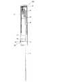
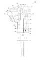
図1は、実施の形態1に係る臓器縫合具の構造を説明する図である。図2は、図1の一部を透視状態で示す図である。図3は、図2のレバーを押し込んだ状態を示す図である。図4は、実施の形態1に係る臓器縫合具の断面模式図である。図5は、実施の形態1に係る臓器縫合具のループ送り機構を中心に示す断面模式図である。図6は、実施の形態1に係る臓器縫合具の縫合糸送り機構を中心に示す断面模式図である。なお、図5では、縫合糸送り機構については図示を省略している。また、図6では、ループ送り機構については図示を省略している。
[Organ suturing tool]
FIG. 1 is a diagram for explaining the structure of an organ suturing tool according toEmbodiment 1. FIG. FIG. 2 is a view showing a part of FIG. 1 in a transparent state. FIG. 3 is a diagram illustrating a state where the lever of FIG. 2 is pushed. FIG. 4 is a schematic cross-sectional view of the organ suturing tool according toEmbodiment 1. FIG. 5 is a schematic cross-sectional view centering on the loop feeding mechanism of the organ suturing tool according to the first embodiment. FIG. 6 is a schematic cross-sectional view centering on the suture feed mechanism of the organ suture tool according toEmbodiment 1. In FIG. 5, the suture feed mechanism is not shown. In FIG. 6, the loop feed mechanism is not shown.

図1〜図3に示すように、臓器縫合具100は、筐体10と、操作用のレバー20とを備える。筐体10の先端側には、縫合糸導入用針2と、ループ導入用針1とが取り付けられている。本実施の形態に係る臓器縫合具100は、後述する図7で示すように、縫合糸導入用針2とループ導入用針1とを患者の腹壁から胃壁内へと穿刺し、縫合糸導入用針2から胃内へと縫合糸5を送り込むとともに、ループ導入用針1から胃内へ縫合糸取出ループ60を送り込むことを機能の一つとしている。  As shown in FIGS. 1 to 3, theorgan suturing instrument 100 includes ahousing 10 and anoperation lever 20. Asuture introduction needle 2 and aloop introduction needle 1 are attached to the distal end side of thehousing 10. As shown in FIG. 7 to be described later, the organ suturinginstrument 100 according to the present embodiment punctures thesuture introduction needle 2 and theloop introduction needle 1 from the abdominal wall of the patient into the stomach wall to introduce the suture thread. One of the functions is to feed thesuture thread 5 from theneedle 2 into the stomach and to feed thesuture extraction loop 60 from theloop introduction needle 1 into the stomach.

そして、筐体10において、概ねループ導入用針1側には、縫合糸取出ループ60をループ導入用針1の先端方向へ順次送り出すとともに、送り出した縫合糸取出ループ60を初期位置に引き戻すためのループ送り機構30が設けられている。また、筐体10において、概ね縫合糸導入用針2側には、縫合糸5を縫合糸導入用針2の先端側へ順次送り出す縫合糸送り機構40を備えている。
なお、以降の説明において、図1〜図3における紙面下側を「先端側」と称し、紙面上側を「基端側」と称する場合がある。また、以降の説明において「時計回り」、「反時計回り」と称する場合があるが、これは、図1〜図3における紙面時計回りと反時計回りをいうものとする。
In thehousing 10, the suture take-out loop 60 is sequentially sent toward the distal end of theloop introduction needle 1 approximately toward theloop introduction needle 1 side, and the sent suture take-out loop 60 is pulled back to the initial position. Aloop feed mechanism 30 is provided. Further, thecasing 10 is provided with asuture feed mechanism 40 that sequentially feeds thesuture 5 to the distal end side of thesuture introduction needle 2 on thesuture introduction needle 2 side.
In the following description, the lower side of the paper surface in FIGS. 1 to 3 may be referred to as the “front end side”, and the upper side of the paper surface may be referred to as the “base end side”. Further, in the following description, there are cases where they are referred to as “clockwise” and “counterclockwise”, and this means the clockwise and counterclockwise directions in FIGS.

筐体10は、臓器縫合具100全体をユニット化するハウジングを構成している。筐体10は、合成樹脂(例えば塩化ビニル樹脂、ポリプロピレン、ポリエチレンなどのポリオレフィン、ポリカーボネート、ABS等)により形成されている。  Thehousing 10 constitutes a housing that unitizes the entire organ suturingtool 100. Thecasing 10 is made of a synthetic resin (for example, a vinyl chloride resin, a polyolefin such as polypropylene or polyethylene, a polycarbonate, an ABS, or the like).

レバー20(操作具)は、レバー支持部21により筐体10に回動可能に取り付けられている。本実施の形態に係るレバー支持部21は、レバー20を回動可能に支持する回動軸と、レバー20を反時計回りに付勢するトーションバネとを有している。このレバー支持部21に設けられたトーションバネのバネ力により、レバー20は図1、図2に示す初期位置に保持されている。レバー20に対して筐体10の方向(図1、2の紙面右側方向)へ押し込む力が加えられると、レバー20は回動して図3に示す押し込み位置に移動する。そして、レバー20へ加えられた力が解除されると、トーションバネのバネ力によりレバー20は初期位置に自動的に復帰する。  The lever 20 (operation tool) is rotatably attached to thehousing 10 by alever support portion 21. Thelever support portion 21 according to the present embodiment includes a rotation shaft that rotatably supports thelever 20 and a torsion spring that biases thelever 20 counterclockwise. Thelever 20 is held at the initial position shown in FIGS. 1 and 2 by the spring force of the torsion spring provided on thelever support 21. When a force for pushing thelever 20 in the direction of the housing 10 (the right side in FIG. 1 and FIG. 2) is applied, thelever 20 rotates and moves to the pushing position shown in FIG. When the force applied to thelever 20 is released, thelever 20 automatically returns to the initial position by the spring force of the torsion spring.

ループ導入用針1は、内腔を有し、その内腔に縫合糸取出ループ60を軸方向に移動可能に収容する穿刺針である。ループ導入用針1は、例えばステンレス等の金属で形成されている。ループ導入用針1は、皮膚への穿刺用の刃面を先端に有している。この刃面は、ループ導入用針1の軸心と斜めに交差する面として形成されている。ループ導入用針1は、その先端開口が縫合糸導入用針2の方向に向かうようにして、筐体10に取り付けられるのが好ましい。  Theloop introduction needle 1 is a puncture needle that has a lumen and accommodates the suture take-out loop 60 in the lumen so as to be movable in the axial direction. Theloop introduction needle 1 is formed of a metal such as stainless steel, for example. Theloop introduction needle 1 has a blade surface for puncturing the skin at the tip. This blade surface is formed as a surface that obliquely intersects the axis of theloop introduction needle 1. Theloop introduction needle 1 is preferably attached to thehousing 10 such that the tip opening thereof is directed toward thesuture introduction needle 2.

なお、ループ導入用針1は、皮膚への穿刺と内腔への縫合糸取出ループ60の挿入ができればよく、形状を特に限定するものではない。例えば、ループ導入用針1としては、外径が21〜17G(好ましくは20〜18G)程度のものを利用するとよい。  Theloop introduction needle 1 is not particularly limited as long as it can puncture the skin and insert the suturethread extraction loop 60 into the lumen. For example, as theloop introduction needle 1, one having an outer diameter of about 21 to 17G (preferably 20 to 18G) may be used.

縫合糸導入用針2は、内腔を有し、その内腔に縫合糸5(図7参照)を軸方向に移動可能に収容する穿刺針である。縫合糸導入用針2は、例えばステンレス等の金属で形成されている。縫合糸導入用針2は、皮膚への穿刺用の刃面を先端に有している。この刃面は、縫合糸導入用針2の軸心と斜めに交差する面として形成されている。特に限定するものではないが、縫合糸導入用針2は、その先端開口がループ導入用針1の方向に向かうようにして、筐体10に取り付けられるのが好ましい。  The suturethread introduction needle 2 is a puncture needle that has a lumen and accommodates the suture thread 5 (see FIG. 7) in the lumen so as to be movable in the axial direction. The suturethread introduction needle 2 is formed of a metal such as stainless steel, for example. The suturethread introduction needle 2 has a blade surface for puncturing the skin at the tip. This blade surface is formed as a surface that obliquely intersects the axis of thesuture introduction needle 2. Although not particularly limited, it is preferable that thesuture introduction needle 2 is attached to thehousing 10 so that the distal end opening thereof is directed toward theloop introduction needle 1.

なお、縫合糸導入用針2は、皮膚への穿刺と内腔への縫合糸5の挿入ができればよく、形状を特に限定するものではない。例えば、縫合糸導入用針2としては、外径が21〜17G(好ましくは20〜18G)程度のものを利用するとよい。  The suturethread introduction needle 2 is not particularly limited in shape as long as it can puncture the skin and insert thesuture thread 5 into the lumen. For example, the suturethread introduction needle 2 may have an outer diameter of about 21 to 17G (preferably 20 to 18G).

ループ導入用針1と縫合糸導入用針2は、筐体10の先端側に、所定距離を隔ててほぼ平行に取り付けられている。ループ導入用針1と縫合糸導入用針2の内腔は、筐体10の内部と連通している。  Theloop introduction needle 1 and thesuture introduction needle 2 are attached to the distal end side of thehousing 10 substantially in parallel with a predetermined distance. The lumens of theloop introduction needle 1 and thesuture introduction needle 2 communicate with the inside of thehousing 10.

針保持プレート3は、平板状の板であり、縫合糸導入用針2とループ導入用針1がそれぞれ挿通可能な穴部が設けられている。針保持プレート3の穴部には、縫合糸導入用針2とループ導入用針1が摺動可能に貫通される。これにより、穿刺時において縫合糸導入用針2とループ導入用針1との距離を一定に保つことができる。また、針保持プレート3は縫合糸導入用針2とループ導入用針1に対して摺動可能であるので、穿刺時に針保持プレート3が作業の妨げとなることもない。また、縫合糸導入用針2とループ導入用針1との距離を一定に保つためには針保持プレート3を設けるのが望ましいが、針保持プレート3を設けない構成とすることもできる。  Theneedle holding plate 3 is a flat plate and is provided with holes through which thesuture introduction needle 2 and theloop introduction needle 1 can be inserted. Thesuture introduction needle 2 and theloop introduction needle 1 are slidably penetrated through the hole of theneedle holding plate 3. Thereby, the distance between the suturethread introduction needle 2 and theloop introduction needle 1 can be kept constant during puncturing. Further, since theneedle holding plate 3 is slidable with respect to thesuture introduction needle 2 and theloop introduction needle 1, theneedle holding plate 3 does not hinder the operation during puncturing. In order to keep the distance between thesuture introduction needle 2 and theloop introduction needle 1 constant, it is desirable to provide theneedle holding plate 3, but a configuration in which theneedle holding plate 3 is not provided may be employed.

[ループ送り機構]
図1〜図3、及び図5を参照して、ループ送り機構30について説明する。
ループ送り機構30は、レバー20からの操作力を受けて回転するギア31、ギア32、ギア33、ギア34、ギア35、ラック36、及びギア34とギア35とに巻掛けられたベルト37を備える。本実施の形態1において、ギア31、ギア32、ギア33、ギア34、及びギア35が本発明の回転運動機構に相当する。また、本実施の形態1において、ラック36が本発明の直線運動機構に相当する。
[Loop feed mechanism]
Theloop feed mechanism 30 will be described with reference to FIGS. 1 to 3 and FIG.
Theloop feeding mechanism 30 receives agear 31, agear 32, agear 33, agear 34, agear 35, arack 36, and abelt 37 wound around thegear 34 and thegear 35, which are rotated by receiving an operation force from thelever 20. Prepare. In the first embodiment, thegear 31, thegear 32, thegear 33, thegear 34, and thegear 35 correspond to the rotational motion mechanism of the present invention. In the first embodiment, therack 36 corresponds to the linear motion mechanism of the present invention.

レバー20には、ギア31とかみ合う多数の歯が円弧状に配列されてなる係止歯部26が設けられている。また、レバー20には、円弧状に形成され、ギア31の回動軸が通過可能な溝22が設けられている。レバー20に筐体10側へ押し込む力が加えられると、係止歯部26とかみ合ったギア31が、時計回りに回転する。レバー20が筐体10側へ移動し、また初期位置に戻る過程において、ギア31の回動軸が溝22を通過する。  Thelever 20 is provided with a lockingtooth portion 26 in which a large number of teeth meshing with thegear 31 are arranged in an arc shape. Further, thelever 20 is provided with agroove 22 which is formed in an arc shape and through which the rotation shaft of thegear 31 can pass. When a force to push thelever 20 toward thehousing 10 is applied, thegear 31 engaged with the lockingtooth portion 26 rotates clockwise. In the process in which thelever 20 moves toward thehousing 10 and returns to the initial position, the rotation shaft of thegear 31 passes through thegroove 22.

ギア32、ギア33は、同軸上に設けられた異なる直径を有するギアである。ギア32はギア31とかみ合い、ギア33はギア34及び後述するラチェット41とかみ合う。レバー20には、円弧状に形成され、ギア33の回動軸が通過可能な溝23が設けられている。ギア31が時計回りに回転すると、ギア31とかみ合ったギア32が反時計回り(ギア31と逆方向)に回転するとともに、ギア32と同軸上に設けられたギア33もまた反時計回り(ギア31と逆方向)に回転する。レバー20が筐体10側へ移動し、また初期位置に戻る過程において、ギア33の回動軸が溝23を通過する。  Thegear 32 and thegear 33 are gears having different diameters provided on the same axis. Thegear 32 meshes with thegear 31, and thegear 33 meshes with thegear 34 and aratchet 41 described later. Thelever 20 is provided with agroove 23 that is formed in an arc shape and through which the rotation shaft of thegear 33 can pass. When thegear 31 rotates clockwise, thegear 32 engaged with thegear 31 rotates counterclockwise (in the opposite direction to the gear 31), and thegear 33 provided coaxially with thegear 32 also rotates counterclockwise (gear). 31). In the process in which thelever 20 moves toward thehousing 10 and returns to the initial position, the rotation shaft of thegear 33 passes through thegroove 23.

ギア34は、ギア33とかみ合うよう構成されている。レバー20には、円弧状に形成され、ギア34の回動軸が通過可能な溝24が設けられている。ギア33が反時計回りに回転すると、ギア33とかみ合ったギア34が時計回り(ギア33と逆方向)に回転する。レバー20が筐体10側へ移動し、また初期位置に戻る過程において、ギア34の回動軸が溝24を通過する。  Thegear 34 is configured to mesh with thegear 33. Thelever 20 is provided with agroove 24 that is formed in an arc shape and through which the rotation shaft of thegear 34 can pass. When thegear 33 rotates counterclockwise, thegear 34 engaged with thegear 33 rotates clockwise (in the opposite direction to the gear 33). In the process in which thelever 20 moves to thehousing 10 side and returns to the initial position, the rotation shaft of thegear 34 passes through thegroove 24.

ギア35は、ベルト37によってギア34に連結されている。レバー20には、円弧状に形成され、ギア35の回動軸が通過可能な溝25が設けられている。ギア34が時計回りに回転すると、ギア34の回転力がベルト37によってギア35に伝達され、ギア35は時計回り(ギア34と同じ方向)に回転する。レバー20が筐体10側へ移動し、また初期位置に戻る過程において、ギア35の回動軸が溝25を通過する。  Thegear 35 is connected to thegear 34 by abelt 37. Thelever 20 is provided with agroove 25 which is formed in an arc shape and through which the rotation shaft of thegear 35 can pass. When thegear 34 rotates clockwise, the rotational force of thegear 34 is transmitted to thegear 35 by thebelt 37, and thegear 35 rotates clockwise (in the same direction as the gear 34). In the process in which thelever 20 moves toward thehousing 10 and returns to the initial position, the rotation shaft of thegear 35 passes through thegroove 25.

ラック36は、ギア35とかみ合う歯を有し、ループ導入用針1の長軸方向と同じ方向に延びている。ギア35が時計回りに回転すると、ギア34とかみ合ったラック36が紙面下方向に移動する。ギア35とラック36とにより、ギア35の回転運動がラック36の直線運動に変換される。  Therack 36 has teeth that mesh with thegear 35, and extends in the same direction as the major axis direction of theloop introduction needle 1. When thegear 35 rotates clockwise, therack 36 engaged with thegear 34 moves downward in the drawing. The rotational movement of thegear 35 is converted into the linear movement of therack 36 by thegear 35 and therack 36.

ラック36の先端側には、縫合糸取出ループ60が連結されている。
ここで、縫合糸取出ループ60(縫合糸取出具)について説明する。
縫合糸取出ループ60は、ループ導入用針1の内腔に軸方向に移動可能に挿入されて使用される。縫合糸取出ループ60は、ループ導入用針1の内腔内を移動可能な細径の軸部61と、軸部61の先端に設けられた環状のループ62とを備える。軸部61の基端は、ラック36に連結される。ループ62の平面視の形状は、略円形の環状である。ループ62は、可撓性を有する材料により構成されており、ループ導入用針1の内部に挿入された状態では、ほぼ直線状に変形してループ導入用針1の内腔に収容されるが、図3に示すようにループ導入用針1の先端から送り出された状態(外力が加わっていない状態)では環状に復元する。
A suture take-out loop 60 is connected to the distal end side of therack 36.
Here, the suture take-out loop 60 (suture take-out tool) will be described.
The suture take-out loop 60 is used by being inserted into the lumen of theloop introduction needle 1 so as to be movable in the axial direction. The suturethread extraction loop 60 includes a small-diameter shaft portion 61 that can move within the lumen of theloop introduction needle 1 and anannular loop 62 provided at the tip of theshaft portion 61. A base end of theshaft portion 61 is connected to therack 36. The shape of theloop 62 in plan view is a substantially circular ring shape. Theloop 62 is made of a flexible material. When theloop 62 is inserted into theloop introduction needle 1, theloop 62 is deformed substantially linearly and is accommodated in the lumen of theloop introduction needle 1. As shown in FIG. 3, in a state where the tip is introduced from the tip of the loop introduction needle 1 (a state where no external force is applied), the loop is restored to an annular shape.

使用状態において、後述する図7(B)に示すように、ループ62の内部には縫合糸5が挿入される。このため、ループ導入用針1の先端から送り出されたループ62の内部に、縫合糸導入用針2の先端から送り出された縫合糸5がより確実に挿入されるよう、ループ62の延びる方向と大きさとが設定されている。例えば、縫合糸導入用針2の延長線上にループ62の中心が位置するような大きさでループ62を形成すると、縫合糸導入用針2から送り出された縫合糸5がより確実にループ62内に挿入される。  In the use state, thesuture thread 5 is inserted into theloop 62 as shown in FIG. For this reason, the direction in which theloop 62 extends so that thesuture thread 5 fed out from the distal end of thesuture introduction needle 2 is more reliably inserted into the inside of theloop 62 fed out from the distal end of theloop introduction needle 1. The size is set. For example, when theloop 62 is formed in such a size that the center of theloop 62 is positioned on the extension line of thesuture introduction needle 2, thesuture 5 fed out from thesuture introduction needle 2 is more reliably contained in theloop 62. Inserted into.

ループ62は、変形可能な部材で構成されていればよく、例えばステンレス鋼線(バネ用高張力ステンレス鋼)、ピアノ線(ニッケルメッキあるいはクロムメッキが施されたピアノ線)、または超弾性合金線(チタンとニッケルの合金、銅と亜鉛の合金(あるいは、それにベリリウム、ケイ素、スズ、アルミニウム、ガリウム等を含めた合金)、ニッケルとアルミニウムの合金等)等で構成することができる。  Theloop 62 only needs to be made of a deformable member, for example, a stainless steel wire (high-strength stainless steel for springs), a piano wire (a piano wire with nickel plating or chrome plating), or a superelastic alloy wire. (Alloys of titanium and nickel, alloys of copper and zinc (or alloys including beryllium, silicon, tin, aluminum, gallium, etc.) and alloys of nickel and aluminum).

軸部61は、金属(例えばステンレス)や合成樹脂(例えば、ポリプロピレン、ポリエチレンなどのポリオレフィン、ポリアミド、PTFE、ETFE等のフッ素樹脂)等を用いて構成することができる。この軸部61は、スタイレット等を利用して構成することができる。なお、ループ62を比較的剛性がある材料で構成する場合には、軸部61とループ62とを同じ材質で構成してもよい。この場合、軸部61とループ62とを、一体に構成してもよく、別体で構成してもよい。  Theshaft portion 61 can be configured using a metal (for example, stainless steel) or a synthetic resin (for example, a polyolefin such as polypropylene or polyethylene, a fluororesin such as polyamide, PTFE, or ETFE). Theshaft portion 61 can be configured using a stylet or the like. In the case where theloop 62 is made of a relatively rigid material, theshaft portion 61 and theloop 62 may be made of the same material. In this case, theshaft portion 61 and theloop 62 may be formed integrally or separately.

このように構成された縫合糸取出ループ60のループ62は、図1、図2に示す初期位置において、ループ導入用針1内に挿入されている。ラック36が臓器縫合具100の先端側(紙面下方向)に移動すると、ラック36に連結された縫合糸取出ループ60もループ導入用針1の軸方向に沿って先端側に送り出される。  Theloop 62 of the suturethread extraction loop 60 configured as described above is inserted into theloop introduction needle 1 at the initial position shown in FIGS. When therack 36 moves to the distal end side (downward in the drawing) of theorgan suturing instrument 100, the suturethread extraction loop 60 connected to therack 36 is also fed to the distal end side along the axial direction of theloop introduction needle 1.

[縫合糸送り機構]
図1〜図3、及び図6を参照して、縫合糸送り機構40について説明する。
縫合糸送り機構は、ラチェット41、摩擦車42、プーリ43、プーリ44、プーリ45、プーリ46、プーリ43とプーリ44に巻掛けられたベルト47、及び縫合糸ガイド溝48を備える。
[Suture feed mechanism]
Thesuture feed mechanism 40 will be described with reference to FIGS. 1 to 3 and FIG. 6.
The suture feed mechanism includes aratchet 41, afriction wheel 42, apulley 43, apulley 44, apulley 45, apulley 46, abelt 47 wound around thepulley 43 and thepulley 44, and asuture guide groove 48.

ラチェット41は、ギア33とかみ合う歯を有する。ラチェット41は、ギア33が反時計回り(縫合糸取出ループ60を送り出す方向)に回転すると、これに連動して時計回りに回転するが、ギア33が時計回りに回転した場合には回転しない構造である。
このラチェット41と同軸上に、摩擦車42が設けられている。摩擦車42は、その外周面においてプーリ43の外周面と当接し、回転力をプーリ43に伝える。また、摩擦車42には巻軸が設けられており、この巻軸に時計回りに縫合糸5が巻き回されている。ギア33が反時計回りに回転すると、ギア33とかみ合ったラチェット41が時計回り(ギア33と逆方向)に回転するとともに、ラチェット41と同軸上に設けられた摩擦車42もまた時計回り(ギア33と逆方向)に回転する。摩擦車42が時計回りに回転すると、摩擦車42に巻かれた縫合糸5が繰り出される。
Theratchet 41 has teeth that mesh with thegear 33. Theratchet 41 rotates clockwise in conjunction with the rotation of thegear 33 counterclockwise (the direction in which the suture take-out loop 60 is fed), but does not rotate when thegear 33 rotates clockwise. It is.
Afriction wheel 42 is provided coaxially with theratchet 41. Thefriction wheel 42 abuts on the outer peripheral surface of thepulley 43 and transmits the rotational force to thepulley 43. Further, thefriction wheel 42 is provided with a winding shaft, and thesuture thread 5 is wound around the winding shaft clockwise. When thegear 33 rotates counterclockwise, theratchet 41 engaged with thegear 33 rotates clockwise (opposite to the gear 33), and thefriction wheel 42 provided coaxially with theratchet 41 also rotates clockwise (gear Rotate in the opposite direction to 33). When thefriction wheel 42 rotates clockwise, thesuture thread 5 wound around thefriction wheel 42 is fed out.

プーリ43は、その外周面において摩擦車42の外周面と当接し、摩擦力により回転する。プーリ43と摩擦車42との当接部においては、摩擦車42から繰り出される縫合糸5が挟まれて保持される。摩擦車42が時計回りに回転すると、プーリ43は摩擦車42との間の摩擦力によって反時計回り(摩擦車42と逆方向)に回転する。このとき、摩擦車42とプーリ43とに挟まれた縫合糸5が、先端方向に向かって送り出される。  Thepulley 43 abuts on the outer peripheral surface of thefriction wheel 42 on the outer peripheral surface thereof, and rotates by frictional force. At the contact portion between thepulley 43 and thefriction wheel 42, thesuture thread 5 fed out from thefriction wheel 42 is sandwiched and held. When thefriction wheel 42 rotates clockwise, thepulley 43 rotates counterclockwise (in the opposite direction to the friction wheel 42) by the frictional force with thefriction wheel 42. At this time, thesuture thread 5 sandwiched between thefriction wheel 42 and thepulley 43 is sent out toward the distal end.

プーリ44とプーリ43との間には、環状のベルト47が張架されている。このベルト47の伝動により、プーリ44は、プーリ43の従動プーリとして機能する。プーリ43が反時計回りに回転すると、プーリ43の回転力がベルト47によりプーリ44に伝達され、プーリ44は反時計回り(プーリ43と同じ方向)に回転する。  Anannular belt 47 is stretched between thepulley 44 and thepulley 43. Due to the transmission of thebelt 47, thepulley 44 functions as a driven pulley of thepulley 43. When thepulley 43 rotates counterclockwise, the rotational force of thepulley 43 is transmitted to thepulley 44 by thebelt 47, and thepulley 44 rotates counterclockwise (the same direction as the pulley 43).

プーリ45は、外周部に溝部を有し、摩擦車42及びプーリ43によって送られた縫合糸5がプーリ45の溝部に嵌められている。プーリ45は、摩擦車42から送られた縫合糸5に張力を付与するとともに、縫合糸5の送り出し方向をガイドする機能を有する。  Thepulley 45 has a groove on the outer periphery, and thesuture thread 5 fed by thefriction wheel 42 and thepulley 43 is fitted in the groove of thepulley 45. Thepulley 45 has a function of applying tension to thesuture thread 5 sent from thefriction wheel 42 and guiding the delivery direction of thesuture thread 5.

プーリ46は、プーリ44との間に縫合糸5を挟むことができる位置に設けられ、その外周面においてプーリ44の外周面と当接し、摩擦力により回転する。プーリ44とプーリ46との当接部においては、縫合糸5が挟まれて保持される。プーリ44が反時計回りに回転すると、プーリ46はプーリ44との間の摩擦力によって時計回り(プーリ44と逆方向)に回転する。このとき、プーリ46とプーリ44とに挟まれた縫合糸5が、先端方向に向かって送り出される。  Thepulley 46 is provided at a position where thesuture thread 5 can be sandwiched between thepulley 44 and the outer peripheral surface thereof abuts on the outer peripheral surface of thepulley 44 and rotates by frictional force. Thesuture thread 5 is sandwiched and held at the contact portion between thepulley 44 and thepulley 46. When thepulley 44 rotates counterclockwise, thepulley 46 rotates clockwise (opposite to the pulley 44) by the frictional force between thepulley 44 and thepulley 44. At this time, thesuture thread 5 sandwiched between thepulley 46 and thepulley 44 is sent out in the distal direction.

プーリ45からプーリ44及びプーリ46との間には、縫合糸5を案内する縫合糸ガイド溝48が設けられている。縫合糸ガイド溝48は、縫合糸導入用針2と同軸であるとともに縫合糸導入用針2の内径とほぼ同じ幅で構成されており、縫合糸ガイド溝48と縫合糸導入用針2とは連なっている。プーリ45により送られた縫合糸5は、縫合糸ガイド溝48を進み、プーリ44及びプーリ46へと至り、さらに縫合糸導入用針2の内腔へと進む。なお、縫合糸ガイド溝48は、プーリ44及びプーリ46の近傍において途切れており、この途切れた部位において縫合糸5がプーリ44及びプーリ46により挟まれて保持される。  Asuture guide groove 48 for guiding thesuture 5 is provided between thepulley 45 and thepulley 44 and thepulley 46. Thesuture guide groove 48 is coaxial with thesuture introduction needle 2 and has the same width as the inner diameter of thesuture introduction needle 2. Thesuture guide groove 48 and thesuture introduction needle 2 are the same. It is lined up. Thesuture thread 5 sent by thepulley 45 advances through thesuture guide groove 48, reaches thepulley 44 and thepulley 46, and further advances to the lumen of the suturethread introduction needle 2. Thesuture guide groove 48 is interrupted in the vicinity of thepulley 44 and thepulley 46, and thesuture 5 is sandwiched and held between thepulley 44 and thepulley 46 at the interrupted portion.

ここで、縫合糸5について説明する。縫合糸5は、生体内に挿通させたときに生体組織に沿って撓ることができる程度の柔軟性と、臓器を吊り上げ可能な程度の引っ張り強度とを有する材料(例えば、ナイロン糸等)で構成されている。また、縫合糸5は、患者に取り付けあるいは取り外す際に切断される。このため、縫合糸5は、ハサミ等の医療現場に備えられている道具で切断可能な材料及び径寸法で構成するのが好ましい。この縫合糸5は、複数回の腹壁と胃壁との固定に十分な長さ分だけ摩擦車42の巻軸に巻かれている。また、複数回の縫合が可能な長さの縫合糸5を、摩擦車42の巻軸に巻いておいてもよい。  Here, thesuture thread 5 will be described. Thesuture thread 5 is made of a material (for example, nylon thread or the like) having a flexibility that can be bent along the living tissue when inserted into the living body and a tensile strength that can lift the organ. It is configured. Thesuture thread 5 is cut when being attached to or removed from the patient. For this reason, it is preferable that thesuture thread 5 is made of a material and a diameter that can be cut with a tool provided in a medical field such as scissors. Thesuture thread 5 is wound around the winding shaft of thefriction wheel 42 by a length sufficient for fixing the abdominal wall and stomach wall a plurality of times. Further, thesuture thread 5 having a length capable of being sutured a plurality of times may be wound around the winding shaft of thefriction wheel 42.

[カッター]
カッター50は、縫合糸5を切断するためのものであり、縫合糸送り機構40の最も先端側に設けられた構成であるプーリ44及びプーリ46よりも、さらに筐体10の先端側に設けられている。本実施の形態では、カッター50は、縫合糸5を切断するための刃51と、刃51に接続され、この刃51を切断方向とは逆方向に付勢するバネ52と、刃51を移動させる操作部53とを備える。また、筐体10には、操作部53を案内する開口部54が設けられている。操作部53は、筐体10に設けられた開口部54から、筐体10の外部へと突出している。術者が操作部53を持ってバネ52の付勢力に反して操作部53をスライドさせると、刃51が移動する。そうすると、刃51は縫合糸5を横断し、このときに刃51によって縫合糸5が切断される。操作部53から術者が手を離すと、バネ52の付勢力により刃51は縫合糸5を横断しない位置に戻る。縫合糸5は、縫合糸送り機構40の先端(プーリ44及びプーリ46)よりも先端側であって、縫合糸導入用針2の基端部よりも基端側において、カッター50により切断される。
[cutter]
Thecutter 50 is for cutting thesuture 5, and is provided further on the distal end side of thehousing 10 than thepulley 44 and thepulley 46, which is the configuration provided on the most distal end side of thesuture feed mechanism 40. ing. In the present embodiment, thecutter 50 is connected to theblade 51 for cutting thesuture 5, thespring 52 that biases theblade 51 in the direction opposite to the cutting direction, and theblade 51 is moved. And anoperation unit 53 to be operated. Thehousing 10 is provided with anopening 54 for guiding theoperation unit 53. Theoperation unit 53 protrudes from theopening 54 provided in thehousing 10 to the outside of thehousing 10. When the surgeon holds theoperation portion 53 and slides theoperation portion 53 against the urging force of thespring 52, theblade 51 moves. Then, theblade 51 crosses thesuture thread 5, and at this time, thesuture thread 5 is cut by theblade 51. When the operator releases the hand from theoperation portion 53, theblade 51 returns to a position where it does not cross thesuture thread 5 by the biasing force of thespring 52. Thesuture thread 5 is cut by thecutter 50 at the distal end side of the distal end (pulley 44 and pulley 46) of thesuture feed mechanism 40 and at the proximal end side of the proximal end portion of thesuture introduction needle 2. .

[臓器縫合具の動作]
(縫合糸取出ループ60及び縫合糸5の送り出し動作)
まず、臓器縫合具100は図1、図2に示す初期状態であるものとする。すなわち、縫合糸取出ループ60のループ62は、ループ導入用針1の内腔に収納されている。また、縫合糸5の一端は摩擦車42の巻軸に固定されており、この一端から所定長さ分(複数回の腹壁と胃壁との固定に十分な長さ分)の縫合糸5が摩擦車42の巻軸に巻き取られている。また、縫合糸5の他端は、プーリ44及びプーリ46による挟持位置よりも先端側(カッター50で切断された位置)に位置している。
[Operation of organ suturing tool]
(Suture take-out loop 60 andsuture 5 delivery operation)
First, it is assumed that theorgan suturing tool 100 is in the initial state shown in FIGS. That is, theloop 62 of the suturethread extraction loop 60 is accommodated in the lumen of theloop introduction needle 1. Further, one end of thesuture thread 5 is fixed to the winding shaft of thefriction wheel 42, and thesuture thread 5 of a predetermined length (a length sufficient for fixing the abdominal wall and the stomach wall a plurality of times) from this one end is rubbed. It is wound around the winding shaft of thecar 42. Further, the other end of thesuture thread 5 is located on the distal end side (position cut by the cutter 50) from the holding position by thepulley 44 and thepulley 46.

この状態において、レバー20に対して筐体10の方向へ押し込む操作力が加えられると、レバー20に設けられた係止歯部26とかみ合っているギア31が時計回りに回転する。ギア31が回転することにより、ギア32及びギア32と同軸上のギア33が反時計回りに回転する。ギア33の回転力は、これとかみ合うギア34及びラチェット41に伝達され、ギア34とラチェット41が時計回りに回転する。  In this state, when an operating force for pushing thelever 20 in the direction of thehousing 10 is applied, thegear 31 engaged with the lockingtooth portion 26 provided on thelever 20 rotates clockwise. As thegear 31 rotates, thegear 32 and thegear 33 coaxial with thegear 32 rotate counterclockwise. The rotational force of thegear 33 is transmitted to themeshing gear 34 and theratchet 41, and thegear 34 and theratchet 41 rotate clockwise.

ギア34の回転は、ベルト37を介してギア35に伝達され、ギア35は時計回りに回転する。そして、ギア35とかみ合っているラック36は、ループ導入用針1の先端側に向かって移動する。ラック36の移動に伴い、ラック36に連結されている縫合糸取出ループ60もまたループ導入用針1の先端側に向かって移動する。レバー20を最奥まで押し込むことで、図3に示すようにループ62が環状に復元し、縫合糸導入用針2の延長線上にループ62の環状部内部が位置する状態となる。  The rotation of thegear 34 is transmitted to thegear 35 via thebelt 37, and thegear 35 rotates clockwise. Therack 36 engaged with thegear 35 moves toward the distal end side of theloop introduction needle 1. As therack 36 moves, the suturethread extraction loop 60 connected to therack 36 also moves toward the distal end side of theloop introduction needle 1. By pushing thelever 20 all the way back, theloop 62 is restored to an annular shape as shown in FIG.

また、ラチェット41が時計回りに回転することにより、これと同軸に設けられた摩擦車42が時計回りに回転し、摩擦車42が回転することによりプーリ43が反時計回りに回転する。摩擦車42とプーリ43との間には縫合糸5が挟持されており、摩擦車42に巻き取られている縫合糸5が繰り出される。繰り出された縫合糸5は、プーリ45に案内されて縫合糸ガイド溝48に導かれて進む。プーリ43の回転は、ベルト47を介してプーリ44に伝達され、プーリ44が反時計回りに回転する。そして、プーリ44とプーリ46との間には縫合糸5が挟持されており、縫合糸5が縫合糸導入用針2の先端方向に向かって送り出される。レバー20を最奥まで押し込むことで、図3に示すように縫合糸5が縫合糸導入用針2の先端から突出し、ループ62の環状部内部を貫通する状態となる。  Further, when theratchet 41 rotates clockwise, thefriction wheel 42 provided coaxially with theratchet 41 rotates clockwise, and when thefriction wheel 42 rotates, thepulley 43 rotates counterclockwise. Thesuture thread 5 is sandwiched between thefriction wheel 42 and thepulley 43, and thesuture thread 5 wound around thefriction wheel 42 is fed out. The drawn-outsuture 5 is guided by thepulley 45 and guided to thesuture guide groove 48 to advance. The rotation of thepulley 43 is transmitted to thepulley 44 via thebelt 47, and thepulley 44 rotates counterclockwise. Thesuture thread 5 is sandwiched between thepulley 44 and thepulley 46, and thesuture thread 5 is sent out toward the distal end direction of the suturethread introduction needle 2. By pushing thelever 20 to the innermost position, thesuture thread 5 protrudes from the distal end of the suturethread introduction needle 2 as shown in FIG.

(縫合糸取出ループ60の引き戻し動作)
術者がレバー20の握りを解除すると、レバー20に対して筐体10の方向へ押し込む操作力が解除され、レバー20はレバー支持部21に設けられたトーションバネのバネ力により、図1、2に示す初期位置に自動的に復帰する。
(Retraction operation of the suture take-out loop 60)
When the surgeon releases the grip of thelever 20, the operation force to push thelever 20 in the direction of thehousing 10 is released, and thelever 20 is moved by the spring force of the torsion spring provided in thelever support portion 21, as shown in FIG. Automatically return to the initial position shown in FIG.

レバー20が初期位置に復帰する過程において、レバー20に設けられた係止歯部26とかみ合っているギア31が反時計回りに回転する。ギア31が回転することにより、ギア32が時計回りに回転するとともに、これと同軸上のギア33が時計回りに回転する。ギア33が回転することにより、ギア34が反時計回りに回転するが、ラチェット41は回転しない。このため、ラチェット41と同軸上に設けられた摩擦車42に巻かれた縫合糸5に対しては、送り出しも引き戻しもなされない。  In the process of returning thelever 20 to the initial position, thegear 31 engaged with the lockingtooth portion 26 provided on thelever 20 rotates counterclockwise. As thegear 31 rotates, thegear 32 rotates clockwise, and thegear 33 coaxial with thegear 32 rotates clockwise. As thegear 33 rotates, thegear 34 rotates counterclockwise, but theratchet 41 does not rotate. For this reason, thesuture thread 5 wound around thefriction wheel 42 provided coaxially with theratchet 41 is neither sent out nor pulled back.

ギア34の回転は、ベルト37を介してギア35に伝達され、ギア35は反時計回りに回転する。そして、ギア35とかみ合っているラック36は、筐体10の基端側に向かって移動する。ラック36の移動に伴い、ラック36に連結されている縫合糸取出ループ60もまた基端側に向かって移動する。レバー20が初期位置に復帰することで、図1、図2に示す状態となる。  The rotation of thegear 34 is transmitted to thegear 35 via thebelt 37, and thegear 35 rotates counterclockwise. Then, therack 36 engaged with thegear 35 moves toward the base end side of thehousing 10. As therack 36 moves, the suture take-out loop 60 connected to therack 36 also moves toward the proximal end side. When thelever 20 returns to the initial position, the state shown in FIGS. 1 and 2 is obtained.

ここで、臓器縫合具100の動作に関連する、各部の寸法関係の一例について説明する。
レバー20に設けられた係止歯部26の長さ(移動可能距離)は、25mmである。また、ギア31の円周の長さは25mmであり、係止歯部26の長さと同じである。ギア33は、減速比が約2.5となるような寸法関係で構成されている。また、ギア34及びギア35は、ギア35においてギア33に対する増速比が約0.7となる寸法関係で構成されている。
Here, an example of the dimensional relationship of each part related to the operation of theorgan suturing tool 100 will be described.
The length (movable distance) of the lockingtooth portion 26 provided on thelever 20 is 25 mm. The circumferential length of thegear 31 is 25 mm, which is the same as the length of the lockingtooth portion 26. Thegear 33 is configured in a dimensional relationship such that the reduction ratio is about 2.5. Further, thegear 34 and thegear 35 are configured in a dimensional relationship in which the speed increasing ratio of thegear 35 with respect to thegear 33 is about 0.7.

ラチェット41及び摩擦車42は、摩擦車42においてギア33に対する減速比が約2となる寸法関係で構成されている。  Theratchet 41 and thefriction wheel 42 are configured in a dimensional relationship such that the reduction ratio with respect to thegear 33 in thefriction wheel 42 is about 2.

図1、図2における初期状態から図3の状態になるまでレバー20が筐体10に押し込まれると、係止歯部26は25mm移動し、係止歯部26の動きがギア31を介してギア33に伝わる過程において約2.5倍(約62.5mm)され、ギア33の動きがギア34を介してギア35に伝わる過程において約0.7倍(約44mm)される。ギア35にかみ合っているラック36は、基端側から先端側に向かって約44mm移動し、この長さ分だけ縫合糸取出ループ60がループ導入用針1の先端に向かって送り出される。
また、ギア33の動きがラチェット41を介して摩擦車42に伝わる過程において約2倍(約125mm)され、この長さ分だけ縫合糸5が縫合糸導入用針2の先端側に向かって送り出される。縫合糸導入用針2の先端からカッター50による切断位置までの長さを100mmとした場合、縫合糸5が約125mm送り出されることによって、縫合糸導入用針2の先端から縫合糸5が約25mm突出することとなる。
When thelever 20 is pushed into thehousing 10 from the initial state in FIGS. 1 and 2 to the state in FIG. 3, the lockingtooth portion 26 moves by 25 mm, and the movement of the lockingtooth portion 26 moves through thegear 31. It is about 2.5 times (about 62.5 mm) in the process of being transmitted to thegear 33, and about 0.7 times (about 44 mm) in the process of transmitting the movement of thegear 33 to thegear 35 via thegear 34. Therack 36 engaged with thegear 35 moves about 44 mm from the proximal end side toward the distal end side, and the suturethread extraction loop 60 is fed toward the distal end of theloop introduction needle 1 by this length.
Further, in the process in which the movement of thegear 33 is transmitted to thefriction wheel 42 via theratchet 41, thesuture thread 5 is sent out toward the distal end side of the suturethread introduction needle 2 by this length. It is. When the length from the tip of thesuture introduction needle 2 to the cutting position by thecutter 50 is 100 mm, thesuture 5 is fed out by about 125 mm, so that thesuture 5 is about 25 mm from the tip of thesuture introduction needle 2. It will protrude.

ここで例示した寸法関係は、筐体10とレバー20とを片手で左右方向に握ってレバー20を押し込む際に、レバー20を押し込みやすい長さ(レバー20の押し込み長さ25mm)であること、縫合糸5を縫合糸取出ループ60で把持できるよう両者を送り出せることを考慮して設定したものであるが、同様の機能を実現できるものであれば例示した寸法関係に限定されない。  The dimensional relationship illustrated here is a length that allows thelever 20 to be easily pushed when thelever 10 is pushed by holding thehousing 10 and thelever 20 in the left-right direction with one hand (the pushing length of thelever 20 is 25 mm). Thesuture thread 5 is set in consideration of the fact that both can be fed out so that the suture thread can be gripped by the suture thread take-out loop 60. However, the dimensions are not limited to the exemplified dimensional relationships as long as the same function can be realized.

また、縫合糸5を挟持するプーリ44及びプーリ46は、筐体10においてなるべく先端側に設けるのが好ましい。このようにすることで、筐体10においてより先端側で縫合糸5が支持されることとなるので、この支持部分と縫合糸導入用針2の起端部(縫合糸導入用針2に縫合糸5が挿入される位置)とを近接させることができる。このため、例えば内臓内に穿刺した縫合糸導入用針2の内腔から体外へのバックフローが生じた場合でも、縫合糸5がよりスムースに縫合糸導入用針2の内腔に挿入される。  In addition, thepulley 44 and thepulley 46 that sandwich thesuture thread 5 are preferably provided on the distal end side of thecasing 10 as much as possible. By doing so, thesuture thread 5 is supported on the distal end side more in thehousing 10, so that the support portion and the leading end portion of the suture thread introduction needle 2 (sewn to the suturethread introduction needle 2 are sutured). The position where theyarn 5 is inserted). For this reason, for example, even when a backflow from the lumen of the suturethread introduction needle 2 punctured into the internal organs to the outside of the body occurs, thesuture thread 5 is more smoothly inserted into the lumen of the suturethread introduction needle 2. .

また、縫合糸5を切断するカッター50の設置位置は、筐体10においてなるべく先端側に設けるのが好ましい。このようにすることで、カッター50による切断位置から縫合糸導入用針2の先端までの距離がより短くなるので、縫合糸5を縫合糸導入用針2の先端へ送り出す送り量を小さくできる。  Moreover, it is preferable that the installation position of thecutter 50 for cutting thesuture thread 5 is provided on the distal end side as much as possible in thehousing 10. By doing in this way, since the distance from the cutting position by thecutter 50 to the tip of thesuture introduction needle 2 becomes shorter, the feed amount for sending thesuture 5 to the tip of thesuture introduction needle 2 can be reduced.

[臓器縫合具の使用状態]
次に、実施の形態1に係る臓器縫合具100の使用状態を説明する。図7は、実施の形態1に係る臓器縫合具の使用状態を説明する図であり、図7(A)〜(E)は順に、縫合糸5による縫合の流れを示している。ここでは、臓器縫合具100を用いて、患者の腹壁102と胃壁101とを縫合する場合を例に、図2、図3及び図7を参照して説明する。
[Usage status of organ suturing tool]
Next, the usage state of theorgan suturing tool 100 according toEmbodiment 1 will be described. FIG. 7 is a diagram for explaining a use state of the organ suturing tool according toEmbodiment 1, and FIGS. 7A to 7E show a flow of suturing with thesuture thread 5 in order. Here, an example in which the patient'sabdominal wall 102 andstomach wall 101 are sutured using theorgan suturing tool 100 will be described with reference to FIGS. 2, 3, and 7.

まず、術者は、患者の口または鼻から胃内に内視鏡を挿入する。次に、術者は、内臓内に十分に気体(例えば二酸化炭素)を供給して内臓を膨張させる。これにより、胃壁101が腹壁102に密着する。次に、縫合糸導入用針2及びループ導入用針1で穿刺しようとする箇所を含め、皮膚103を消毒する。それから、内視鏡から放たれる光により内臓の位置を確認し、この部位に局所麻酔を行う。なお、穿刺部位の確認は、例えば、胃内に内視鏡を挿入した状態で体表側を指で圧迫し、指での圧迫により胃壁が凹んだ位置を内視鏡画像で確認することにより行うことができる(指サイン)。  First, the operator inserts an endoscope into the stomach through the patient's mouth or nose. Next, the surgeon supplies gas (for example, carbon dioxide) sufficiently in the internal organs to expand the internal organs. Thereby, thestomach wall 101 adheres to theabdominal wall 102. Next, theskin 103 including the portion to be punctured with thesuture introduction needle 2 and theloop introduction needle 1 is disinfected. Then, the position of the viscera is confirmed by the light emitted from the endoscope, and local anesthesia is performed on this site. The puncture site is confirmed by, for example, pressing the surface of the body with a finger while the endoscope is inserted into the stomach, and confirming the position where the stomach wall is recessed by the finger with an endoscopic image. Can (finger sign).

図7(A)に示すように、穿刺部位を確認した術者は、臓器縫合具100の縫合糸導入用針2及びループ導入用針1を患者の腹壁102に穿刺し、縫合糸導入用針2及びループ導入用針1の先端を胃壁101の内部に突出させる。縫合糸導入用針2及びループ導入用針1には針保持プレート3が取り付けられているので、縫合糸導入用針2とループ導入用針1との距離を一定に保つことができ、所望の位置に穿刺しやすい。  As shown in FIG. 7A, the operator who has confirmed the puncture site punctures theabdominal wall 102 of the patient with thesuture introduction needle 2 and theloop introduction needle 1 of theorgan suture instrument 100, and then introduces the suture introduction needle. 2 and the tip of theloop introduction needle 1 are projected into thestomach wall 101. Since theneedle holding plate 3 is attached to thesuture introduction needle 2 and theloop introduction needle 1, the distance between thesuture introduction needle 2 and theloop introduction needle 1 can be kept constant, and a desired value can be obtained. Easy to puncture the position.

次に、術者は、臓器縫合具100のレバー20を握り、レバー20を筐体10側へと押し込む。このようにすると、ループ送り機構30により、ループ導入用針1の先端から縫合糸取出ループ60の先端にあるループ62が突出する。所定長さだけ突出したループ62は、図7(B)に示すように、環状に復元し、縫合糸導入用針2の方向に向かって延びる。
また、術者が臓器縫合具100のレバー20を握ってレバー20を筐体10側へと押し込むことで、縫合糸送り機構40により、縫合糸導入用針2内を縫合糸5が先端に向かって送り出される。図7(B)に示すように、ループ62がループ導入用針1の先端から突出するのに遅れて、縫合糸5が縫合糸導入用針2の先端から突出する。このようにすることで、環状に復元した(あるいは環状に復元しつつある)ループ62の環状部内部に、縫合糸5が挿入される。
Next, the operator holds thelever 20 of theorgan suturing tool 100 and pushes thelever 20 toward thehousing 10 side. In this way, theloop feeding mechanism 30 causes theloop 62 at the distal end of the suturethread extraction loop 60 to protrude from the distal end of theloop introduction needle 1. As shown in FIG. 7B, theloop 62 protruding by a predetermined length is restored to an annular shape and extends toward thesuture introduction needle 2.
Further, when the surgeon grasps thelever 20 of theorgan suturing device 100 and pushes thelever 20 toward thehousing 10, the suturethread feeding mechanism 40 causes thesuture thread 5 to move toward the tip in thesuture introduction needle 2. Sent out. As shown in FIG. 7B, thesuture thread 5 projects from the distal end of thesuture introduction needle 2 after theloop 62 projects from the distal end of theloop introduction needle 1. By doing so, thesuture thread 5 is inserted into the annular portion of theloop 62 restored to the annular shape (or being restored to the annular shape).

図7(C)は、臓器縫合具100のレバー20を最奥まで握り込んだ状態における縫合糸取出ループ60及び縫合糸5の状態を示している。図7(C)に示すように、縫合糸取出ループ60のループ62の環状部内部を、縫合糸5が貫通した状態となる。  FIG. 7C shows a state of the suturethread extraction loop 60 and thesuture thread 5 in a state where thelever 20 of theorgan suturing tool 100 is grasped to the innermost position. As shown in FIG. 7C, thesuture thread 5 penetrates through the inside of the annular portion of theloop 62 of the suture thread take-out loop 60.

ループ62内に縫合糸5が挿入されたことを確認した術者は、臓器縫合具100のレバー20の握りを解除する。このようにすることで、レバー20が初期位置に戻る過程において、ループ送り機構30を構成する各種ギアは縫合糸取出ループ60を送り出す際と逆方向に回転し、ラック36が初期位置に戻り、ラック36に連結された縫合糸取出ループ60がループ導入用針1の基端側に引き戻される。このとき、図7(D)に示すように、縫合糸取出ループ60のループ62内に挿入されている縫合糸5は、ループ62に係合されてループ導入用針1側に引き寄せられる。ここで、ループ送り機構30からの力の伝達を受けるラチェット41は、縫合糸5を送り出す方向に回転する場合にのみループ送り機構30のギア33とかみ合う構成であるので、臓器縫合具100のレバー20の握りを解除しても縫合糸5が摩擦車42に巻き戻されることはない。  The operator who confirms that thesuture thread 5 has been inserted into theloop 62 releases the grip of thelever 20 of theorgan suturing tool 100. In this way, in the process in which thelever 20 returns to the initial position, the various gears constituting theloop feeding mechanism 30 rotate in the opposite direction to that when the suture take-out loop 60 is fed, and therack 36 returns to the initial position, The suturethread extraction loop 60 connected to therack 36 is pulled back to the proximal end side of theloop introduction needle 1. At this time, as shown in FIG. 7D, thesuture thread 5 inserted into theloop 62 of the suture thread take-out loop 60 is engaged with theloop 62 and pulled toward theloop introduction needle 1 side. Here, theratchet 41 that receives the transmission of force from theloop feeding mechanism 30 is configured to mesh with thegear 33 of theloop feeding mechanism 30 only when rotating in the direction in which thesuture 5 is fed out. Even if the grip of 20 is released, thesuture thread 5 is not rewound onto thefriction wheel 42.

次に、術者は、カッター50を操作して縫合糸5を切断する。このようにすると、患者側の縫合糸5の一端は縫合糸取出ループ60のループ62に係合され、他端は自由端となる。
次に、術者は、患者の体から縫合糸導入用針2とループ導入用針1とを引き抜く。このようにすると、図7(E)に示すように、腹壁102及び胃壁101を貫通した縫合糸5の両端が、体表側に露出した状態となる。なお、縫合糸導入用針2及びループ導入用針1を患者から引き抜いたときに、縫合糸5の自由端が患者の体内に入り込んでしまわないよう、縫合糸5を切断する位置(カッター50の設置位置と縫合糸導入用針2の先端位置)とを設定するものとする。そして、術者が、露出した縫合糸5の両端を結びつけることで、縫合処理が終了する。
なお、ここで説明した手技においては、術者が縫合糸5を切断した後に患者の体から縫合糸導入用針2とループ導入用針1とを引き抜くものとしたが、これとは逆に、術者が患者の体から縫合糸導入用針2とループ導入用針1とを引き抜いた後に縫合糸5を切断することもできる。
Next, the surgeon operates thecutter 50 to cut thesuture 5. In this way, one end of the patient-side suture 5 is engaged with theloop 62 of the suture take-out loop 60, and the other end is a free end.
Next, the operator pulls out thesuture introduction needle 2 and theloop introduction needle 1 from the patient's body. If it does in this way, as shown in FIG.7 (E), the both ends of thesuture thread 5 which penetrated theabdominal wall 102 and thestomach wall 101 will be in the state exposed to the body surface side. It should be noted that when thesuture introduction needle 2 and theloop introduction needle 1 are pulled out from the patient, thesuture thread 5 is cut so that the free end of thesuture thread 5 does not enter the patient's body (of the cutter 50). The installation position and the tip position of the suture thread introduction needle 2) are set. Then, when the operator ties both ends of the exposedsuture thread 5, the suturing process is completed.
In the procedure described here, the operator pulls out thesuture introduction needle 2 and theloop introduction needle 1 from the patient's body after cutting thesuture 5, but on the contrary, Thesuture thread 5 can be cut after the surgeon pulls out thesuture introduction needle 2 and theloop introduction needle 1 from the patient's body.

以上のように、本実施の形態1の臓器縫合具100によれば、レバー20に対する一操作(レバー20を握る操作)により、ループ導入用針1から縫合糸取出ループ60を突出させるとともに、縫合糸導入用針2の先端から縫合糸取出ループ60のループ62内に向けて縫合糸5を突出させることができる。このように、操作が簡便であるので、例えば1名の術者であっても効率よく作業を行うことができる。また、レバー20への操作を受けて作動する縫合糸送り機構40によって縫合糸5を縫合糸導入用針2に送ることができるので、従来のように術者が縫合糸を持って穿刺針に送る手技と比較して、内臓内から体外へのバックフローが生じた場合でも円滑に縫合糸5を送ることができる。  As described above, according to theorgan suturing tool 100 of the first embodiment, thesuture extraction loop 60 is protruded from theloop introduction needle 1 and sutured by one operation on the lever 20 (operation for grasping the lever 20). Thesuture 5 can be protruded from the tip of thesuture introduction needle 2 into theloop 62 of the suture take-out loop 60. As described above, since the operation is simple, for example, even one surgeon can work efficiently. In addition, since thesuture thread 5 can be sent to thesuture introduction needle 2 by thesuture feed mechanism 40 that operates in response to the operation of thelever 20, the surgeon holds the suture as a puncture needle as in the prior art. Compared with the technique of sending, thesuture thread 5 can be sent smoothly even when a back flow from the internal organs to the outside of the body occurs.

また、本実施の形態1の臓器縫合具100によれば、筐体10側に押し込まれたレバー20は、レバー20に対する握りを解除することにより自動的に初期位置に復帰する構成とした。このため、レバー20に対する一操作(握って押し込んだレバー20の握りを解除する)により、縫合糸取出ループ60をループ導入用針1の内腔に引き戻すことができる。このように、レバー20を握り、そして、握りを解除する、という簡便な操作によって腹壁と内臓壁とを縫合できるので、効率よく作業を行うことができる。  In addition, according to theorgan suturing tool 100 of the first embodiment, thelever 20 pushed into thehousing 10 is configured to automatically return to the initial position by releasing the grip on thelever 20. For this reason, thesuture extraction loop 60 can be pulled back to the lumen of theloop introduction needle 1 by one operation on the lever 20 (releasing the grip of thelever 20 that has been grasped and pushed in). Thus, since the abdominal wall and the visceral wall can be sutured by a simple operation of grasping thelever 20 and releasing the grasp, the work can be performed efficiently.

また、本実施の形態1の臓器縫合具100では、予め筐体10内の摩擦車42に巻き取られた状態の縫合糸5を、縫合糸導入用針2の先端から送り出すことができる。このため、術者は、腹壁と内臓壁とを縫合する際に、自ら縫合糸5を縫合糸導入用針2に挿入する必要がなく、術者の作業性を格段に向上させることができる。  Further, in theorgan suturing tool 100 according to the first embodiment, thesuture thread 5 that has been wound around thefriction wheel 42 in thehousing 10 in advance can be sent out from the distal end of thesuture introduction needle 2. For this reason, when the operator sutures the abdominal wall and the visceral wall, the operator does not need to insert thesuture thread 5 into thesuture introduction needle 2 himself, and the operator's workability can be greatly improved.

また、本実施の形態1では、縫合糸5の一端が摩擦車42に巻き取られた状態のまま他端側を切断できるカッター50を備えた。このため、摩擦車42に複数回の縫合が可能な長さの縫合糸5を予め巻いておくことで、臓器縫合具100を複数回の臓器固定に用いることができる。使用する度に術者自らが縫合糸5を縫合糸導入用針2に挿入する必要もないので、術者の作業性が格段に向上し、作業時間を大幅に短縮することができる。  Further, in the first embodiment, thecutter 50 that can cut the other end side with the one end of thesuture thread 5 wound around thefriction wheel 42 is provided. For this reason, theorgan suture tool 100 can be used for multiple times of organ fixation by winding thesuture thread 5 having a length capable of multiple times of suture around thefriction wheel 42 in advance. Since it is not necessary for the surgeon himself to insert thesuture thread 5 into the suturethread introduction needle 2 each time it is used, the operator's workability is greatly improved, and the working time can be greatly shortened.

実施の形態2.
前述の実施の形態1では、レバー20の握りを解除するとレバー20が自動的に初期位置に復帰する構成であったが、本実施の形態2では、レバー20を初期位置に復帰させる他の構成例について説明する。本実施の形態2では、実施の形態1との相違点を中心に説明する。
Embodiment 2. FIG.
In the first embodiment described above, thelever 20 automatically returns to the initial position when thelever 20 is released. In the second embodiment, however, thelever 20 is returned to the initial position. An example will be described. In the second embodiment, the difference from the first embodiment will be mainly described.

図8は、実施の形態2に係る臓器縫合具の構造を説明する図である。図9は、図8のレバーを押し込んだ状態を示す図である。
本実施の形態2の臓器縫合具100は、レバー20を筐体10に支持するレバー支持部21Aが実施の形態1と異なる。レバー支持部21Aは、レバー20を回動可能に支持する回動軸を備えているが、実施の形態1のようなトーションバネを内蔵していない。
FIG. 8 is a diagram for explaining the structure of the organ suturing device according to the second embodiment. FIG. 9 is a diagram illustrating a state where the lever of FIG. 8 is pushed.
Theorgan suturing tool 100 according to the second embodiment is different from the first embodiment in alever support portion 21A that supports thelever 20 on thehousing 10. Thelever support portion 21A includes a rotation shaft that rotatably supports thelever 20, but does not incorporate a torsion spring as in the first embodiment.

また、レバー20には、術者が指を挿入することができる程度の内径を有する指掛部27が設けられている。  Further, thelever 20 is provided with afinger hooking portion 27 having an inner diameter that allows an operator to insert a finger.

このような構成において、術者がレバー20を握ることで、筐体10側にレバー20を押し込み、図9に示す状態にすることができる。
そして、術者が自身の指をレバー20の指掛部27に入れて引っかけ、レバー20の押し込み方向とは逆方向に動かすことで、レバー20を引き戻し、図8に示す状態に戻すことができる。すなわち、レバー20を術者自らが引き戻すことで、レバー20に対する押し込み操作を解除している。
In such a configuration, when the surgeon grasps thelever 20, thelever 20 can be pushed into thehousing 10 and the state shown in FIG. 9 can be obtained.
Then, the operator puts his / her finger in thefinger hook portion 27 of thelever 20 and hooks it, and moves thelever 20 in the direction opposite to the pushing direction of thelever 20, thereby pulling thelever 20 back to the state shown in FIG. 8. . That is, the push-in operation on thelever 20 is released by the operator pulling thelever 20 back.

このように、レバー20を術者の操作によって初期位置に引き戻す構成としてもよく、実施の形態1と同様に簡便な操作によって腹壁と内臓壁とを縫合できるので、効率よく作業を行うことができる。
なお、指掛部27は、術者の操作によりレバー20を初期位置に引き戻して押し込み操作を解除することのできる構成であれば図8、図9に図示したものに限らず、例えば、半円形状としても良い。また、指掛部27に代えて、術者が指で摘むことのできるような把持部を設けてもよい。
Thus, thelever 20 may be configured to be pulled back to the initial position by the operator's operation, and since the abdominal wall and the visceral wall can be sutured by a simple operation as in the first embodiment, the work can be performed efficiently. .
Thefinger hooking portion 27 is not limited to the one shown in FIGS. 8 and 9 as long as thelever 20 can be pulled back to the initial position by the operator's operation to release the pushing operation. It is good also as a shape. Further, instead of thefinger hooking portion 27, a gripping portion that can be grasped by a surgeon with a finger may be provided.

なお、上記実施の形態では、互いにかみ合う歯を有する歯車機構により運動を伝達する構成例を示したが、運動を伝達する具体的構成はこれに限らず、例えば摩擦により伝動する構成としてもよい。また、ループ送り機構や縫合糸送り機構を構成するギア、ラック、プーリ等の数や、これらの間における伝動機構についても、実施の形態で例示したものに限定しない。  In the above-described embodiment, the configuration example in which the motion is transmitted by the gear mechanism having the meshing teeth is shown. However, the specific configuration for transmitting the motion is not limited thereto, and may be a configuration in which the motion is transmitted by friction, for example. Further, the number of gears, racks, pulleys, and the like constituting the loop feeding mechanism and the suture feeding mechanism, and the transmission mechanism between them are not limited to those exemplified in the embodiment.

1 ループ導入用針、2 縫合糸導入用針、3 針保持プレート、5 縫合糸、10 筐体、20 レバー、21 レバー支持部、21A レバー支持部、22 溝、23 溝、24 溝、25 溝、26 係止歯部、27 指掛部、30 ループ送り機構、31 ギア、32 ギア、33 ギア、34 ギア、35 ギア、36 ラック、37 ベルト、40 縫合糸送り機構、41 ラチェット、42 摩擦車、43 プーリ、44 プーリ、45 プーリ、46 プーリ、47 ベルト、48 縫合糸ガイド溝、50 カッター、51 刃、52 バネ、53 操作部、54 開口部、60 縫合糸取出ループ、61 軸部、62 ループ、100 臓器縫合具、101 胃壁、102 腹壁、103 皮膚。  1 loop introduction needle, 2 suture introduction needle, 3 needle holding plate, 5 suture, 10 housing, 20 lever, 21 lever support, 21A lever support, 22 groove, 23 groove, 24 groove, 25 groove , 26 Locking tooth part, 27 Finger hook part, 30 Loop feed mechanism, 31 gear, 32 gear, 33 gear, 34 gear, 35 gear, 36 rack, 37 belt, 40 Suture feed mechanism, 41 ratchet, 42 Friction wheel , 43 Pulley, 44 Pulley, 45 Pulley, 46 Pulley, 47 Belt, 48 Suture guide groove, 50 Cutter, 51 Blade, 52 Spring, 53 Operation part, 54 Opening part, 60 Suture take-out loop, 61 Shaft part, 62 Loop, 100 organ suturing device, 101 stomach wall, 102 abdominal wall, 103 skin.

Claims (8)

Translated fromJapanese
縫合糸導入用針と、
前記縫合糸導入用針と所定距離を隔ててほぼ平行に設けられたループ導入用針と、
前記縫合糸導入用針及び前記ループ導入用針の基端側と連通するようにして前記縫合糸導入用針及び前記ループ導入用針を支持する筐体と、
弾性変形可能なループを先端側に有する縫合糸取出具と、
術者による操作を受け付ける操作具と、
前記操作具に対する操作を受けると、前記縫合糸取出具を、前記ループ導入用針の内腔の先端方向へ送り出すループ送り機構と、
前記操作具に対する前記操作を受けると、前記筐体内部に収納された状態の縫合糸を、前記縫合糸導入用針の内腔の先端方向へ送り出す縫合糸送り機構とを備えた
ことを特徴とする臓器縫合具。
A suture introduction needle;
A loop introduction needle provided substantially parallel to the suture introduction needle at a predetermined distance;
A housing that supports the suture introduction needle and the loop introduction needle so as to communicate with a proximal end side of the suture introduction needle and the loop introduction needle;
A suture extractor having an elastically deformable loop on the distal end side;
An operation tool for receiving an operation by the surgeon;
When receiving an operation on the operation tool, a loop feeding mechanism that feeds the suture take-out tool toward the distal end of the lumen of the loop introduction needle;
A suture feed mechanism that feeds the suture stored in the housing toward the distal end of the lumen of the suture introduction needle when receiving the operation on the operation tool; Organ suture tool.
前記縫合糸送り機構は、前記縫合糸を前記縫合糸導入用針の先端から送り出した状態を維持し、
前記ループ送り機構は、前記縫合糸取出具を前記ループ導入用針の先端から送り出した後、前記縫合糸取出具を前記ループ導入用針内に収容することで、前記縫合糸を前記ループ導入用針の先端で把持する
ことを特徴とする請求項1記載の臓器縫合具。
The suture feed mechanism maintains the state in which the suture is fed from the tip of the suture introduction needle,
The loop feeding mechanism feeds the suture take-out tool from the tip of the loop introduction needle, and then accommodates the suture take-out tool in the loop introduction needle so that the suture is introduced into the loop introduction needle. The organ suturing device according to claim 1, wherein the organ suturing device is grasped by a tip of a needle.
前記ループ送り機構は、前記操作具に対する操作が解除されると、前記縫合糸取出具を初期位置に引き戻し、
前記縫合糸送り機構は、前記操作具に対する操作が解除された場合であっても、前記縫合糸を引き戻さないよう構成されている
ことを特徴とする請求項1又は請求項2に記載の臓器縫合具。
When the operation on the operation tool is released, the loop feeding mechanism pulls the suture take-out tool back to the initial position,
The organ suture according to claim 1 or 2, wherein the suture feed mechanism is configured not to pull back the suture even when the operation on the operation tool is released. Ingredients.
前記縫合糸送り機構は、前記操作具に対する操作を受けると、巻き取られた状態の前記縫合糸を繰り出す巻軸を備えた
ことを特徴とする請求項1〜請求項3のいずれか一項に記載の臓器縫合具。
The said suture thread feeding mechanism was equipped with the winding axis which pays out the said suture thread of the wound state, if operation with respect to the said operation tool is received. The Claim 1 characterized by the above-mentioned. The organ suturing device described.
前記操作具に対して操作されると、その操作力が、前記ループ送り機構を介して前記縫合糸送り機構に伝達される
ことを特徴とする請求項1〜請求項4のいずれか一項に記載の臓器縫合具。
When the operation tool is operated, the operation force is transmitted to the suture feed mechanism via the loop feed mechanism. The organ suturing device described.
前記ループ送り機構は、
前記操作具に対する操作力を受けて回転する回転運動機構と、
前記縫合糸取出具の基端側と接続され、前記回転運動機構からの伝動により前記ループ導入用針の長軸方向に直線運動する直線運動機構とを備えた
ことを特徴とする請求項1〜請求項5のいずれか一項に記載の臓器縫合具。
The loop feed mechanism is
A rotational movement mechanism that rotates in response to an operation force applied to the operation tool;
A linear motion mechanism that is connected to a proximal end side of the suture thread extractor and linearly moves in a major axis direction of the loop introduction needle by transmission from the rotational motion mechanism. The organ suturing tool according to claim 5.
前記操作具は、前記筐体側へ押し込み操作されることで移動し、この移動力が操作力として前記ループ送り機構に伝達される
ことを特徴とする請求項1〜請求項6のいずれか一項に記載の臓器縫合具。
The said operation tool moves by being pushed in to the said housing | casing side, This movement force is transmitted to the said loop feed mechanism as operation force. The any one of Claims 1-6 characterized by the above-mentioned. The organ suturing device according to 1.
前記縫合糸送り機構よりも先端側であって、前記縫合糸導入用針の基端部よりも基端側に、前記縫合糸を切断する切断具を備えた
ことを特徴とする請求項1〜請求項7のいずれか一項に記載の臓器縫合具。
The cutting tool which cut | disconnects the said suture is provided in the front end side rather than the said suture feed mechanism, and the base end side of the said needle | hook for suture introduction | transduction. The organ suturing tool according to claim 7.
JP2011126189A2011-06-062011-06-06 Organ suturing deviceActiveJP5818519B2 (en)

Priority Applications (1)

Application NumberPriority DateFiling DateTitle
JP2011126189AJP5818519B2 (en)2011-06-062011-06-06 Organ suturing device

Applications Claiming Priority (1)

Application NumberPriority DateFiling DateTitle
JP2011126189AJP5818519B2 (en)2011-06-062011-06-06 Organ suturing device

Publications (2)

Publication NumberPublication Date
JP2012249927Atrue JP2012249927A (en)2012-12-20
JP5818519B2 JP5818519B2 (en)2015-11-18

Family

ID=47523334

Family Applications (1)

Application NumberTitlePriority DateFiling Date
JP2011126189AActiveJP5818519B2 (en)2011-06-062011-06-06 Organ suturing device

Country Status (1)

CountryLink
JP (1)JP5818519B2 (en)

Cited By (3)

* Cited by examiner, † Cited by third party
Publication numberPriority datePublication dateAssigneeTitle
KR101548638B1 (en)*2015-03-092015-08-31전찬영Apparatus for inserting threads
CN113520480A (en)*2021-07-142021-10-22贵州医科大学附属医院Specimen sampling device for blood tumor
CN119074088A (en)*2024-08-262024-12-06北京市春立正达医疗器械股份有限公司 A wire guide for facilitating wire guiding in meniscus surgery

Citations (1)

* Cited by examiner, † Cited by third party
Publication numberPriority datePublication dateAssigneeTitle
US5722981A (en)*1993-10-081998-03-03Tahoe Surgical InstrumentsDouble needle ligature device

Patent Citations (1)

* Cited by examiner, † Cited by third party
Publication numberPriority datePublication dateAssigneeTitle
US5722981A (en)*1993-10-081998-03-03Tahoe Surgical InstrumentsDouble needle ligature device

Cited By (3)

* Cited by examiner, † Cited by third party
Publication numberPriority datePublication dateAssigneeTitle
KR101548638B1 (en)*2015-03-092015-08-31전찬영Apparatus for inserting threads
CN113520480A (en)*2021-07-142021-10-22贵州医科大学附属医院Specimen sampling device for blood tumor
CN119074088A (en)*2024-08-262024-12-06北京市春立正达医疗器械股份有限公司 A wire guide for facilitating wire guiding in meniscus surgery

Also Published As

Publication numberPublication date
JP5818519B2 (en)2015-11-18

Similar Documents

PublicationPublication DateTitle
JP5010178B2 (en) Medical instruments
JP4814274B2 (en) Medical instruments
JP3880907B2 (en) Endoscopic suture device
US8540736B2 (en)Spool configured to retain suture for a suture system
JP2007296319A (en)Medical instrument and method for fixing internal organ
JP2007229472A (en) Cap that can be attached to the tip of the endoscope
JP2007075613A (en) Biological tissue treatment device cartridge
US20200069306A1 (en)Suturing device and methods of use thereof
JP5738039B2 (en) Medical suture tool
JP5946335B2 (en) Medical suture tool
JP5818519B2 (en) Organ suturing device
JP5963559B2 (en) Medical suture tool
JP5832216B2 (en) Medical suture tool
JP5943748B2 (en) Medical suture tool
JP5743828B2 (en) Medical suture tool
JP7188435B2 (en) Suture device
JP5749563B2 (en) Medical suture tool
JP7264149B2 (en) Suture device
JP5863313B2 (en) Medical suture tool
CN110719756B (en) suturing device
JP6124527B2 (en) Medical suture tool
JP6053369B2 (en) Medical suture tool
JP4217462B2 (en) Biological tissue suturing device
JPH08154941A (en)Knot forming instrument
WO2019163306A1 (en)Bi-directional medical suturing device and method for operating same

Legal Events

DateCodeTitleDescription
A621Written request for application examination

Free format text:JAPANESE INTERMEDIATE CODE: A621

Effective date:20140331

A977Report on retrieval

Free format text:JAPANESE INTERMEDIATE CODE: A971007

Effective date:20150128

A131Notification of reasons for refusal

Free format text:JAPANESE INTERMEDIATE CODE: A131

Effective date:20150217

A521Request for written amendment filed

Free format text:JAPANESE INTERMEDIATE CODE: A523

Effective date:20150417

TRDDDecision of grant or rejection written
A01Written decision to grant a patent or to grant a registration (utility model)

Free format text:JAPANESE INTERMEDIATE CODE: A01

Effective date:20150915

A61First payment of annual fees (during grant procedure)

Free format text:JAPANESE INTERMEDIATE CODE: A61

Effective date:20150929

R150Certificate of patent or registration of utility model

Ref document number:5818519

Country of ref document:JP

Free format text:JAPANESE INTERMEDIATE CODE: R150

S531Written request for registration of change of domicile

Free format text:JAPANESE INTERMEDIATE CODE: R313531

R350Written notification of registration of transfer

Free format text:JAPANESE INTERMEDIATE CODE: R350

R250Receipt of annual fees

Free format text:JAPANESE INTERMEDIATE CODE: R250

R250Receipt of annual fees

Free format text:JAPANESE INTERMEDIATE CODE: R250

R250Receipt of annual fees

Free format text:JAPANESE INTERMEDIATE CODE: R250

R250Receipt of annual fees

Free format text:JAPANESE INTERMEDIATE CODE: R250

R250Receipt of annual fees

Free format text:JAPANESE INTERMEDIATE CODE: R250

R250Receipt of annual fees

Free format text:JAPANESE INTERMEDIATE CODE: R250

R250Receipt of annual fees

Free format text:JAPANESE INTERMEDIATE CODE: R250


[8]ページ先頭

©2009-2025 Movatter.jp