JP2012248031A - Electronic apparatus, endoscopic device, and program module update method of electronic apparatus - Google Patents
Electronic apparatus, endoscopic device, and program module update method of electronic apparatusDownload PDFInfo
- Publication number
- JP2012248031A JP2012248031AJP2011119636AJP2011119636AJP2012248031AJP 2012248031 AJP2012248031 AJP 2012248031AJP 2011119636 AJP2011119636 AJP 2011119636AJP 2011119636 AJP2011119636 AJP 2011119636AJP 2012248031 AJP2012248031 AJP 2012248031A
- Authority
- JP
- Japan
- Prior art keywords
- program module
- update
- electronic device
- updated
- program
- Prior art date
- Legal status (The legal status is an assumption and is not a legal conclusion. Google has not performed a legal analysis and makes no representation as to the accuracy of the status listed.)
- Abandoned
Links
Images


Landscapes
- Stored Programmes (AREA)
- Endoscopes (AREA)
Abstract
Translated fromJapaneseDescription
Translated fromJapanese本発明は、電子機器、内視鏡装置及び電子機器のプログラムモジュール更新方法に関する。 The present invention relates to an electronic apparatus, an endoscope apparatus, and a program module update method for the electronic apparatus.
電子機器には、ハードウェアの基本的な制御を行うファームウェアが組み込まれており、新たな機能の追加や、不具合の修正は、ファームウェアのバージョンアップで実現されている。一般にファームウェアは、各電子デバイスに対応する複数のプログラムモジュールで構成されており、これら各プログラムモジュールは、それぞれ個別に改変されてバージョン情報で管理されている。このようなプログラムモジュールを新しいバージョンに更新する際、プログラムモジュールの新たに追加、変更された機能が制御パラメータを有する場合、この制御パラメータの設定値を新たに電子機器に設定する必要がある。
制御パラメータを未設定状態のままにしておくと、電子機器の実使用時になって制御パラメータの設定が要求されることとなり、通常の作業に加えて設定作業を行わねばならず、作業が煩わしくなる。そこで、プログラムモジュール更新後の初回の機器起動時に、制御パラメータを設定する処理を行う方法が特許文献1に提案されている。The electronic device incorporates firmware that performs basic hardware control, and the addition of new functions and the correction of defects are realized by upgrading the firmware. In general, the firmware is composed of a plurality of program modules corresponding to each electronic device, and each program module is individually modified and managed by version information. When such a program module is updated to a new version, if a newly added or changed function of the program module has a control parameter, it is necessary to newly set a setting value of the control parameter in the electronic device.
If the control parameters are left unset, the setting of the control parameters is required when the electronic device is actually used, and the setting work must be performed in addition to the normal work, which is cumbersome. . Therefore,
しかしながら、特許文献1の方法では、プログラムモジュールを更新する作業と制御パラメータを設定する作業とが、機器の再起動を挟んで行われる。そのため、操作者はプログラムモジュールの更新と同時に制御パラメータを設定することができず、非効率で煩雑な作業を強いられる。また、プログラムモジュールの更新時に制御パラメータを設定しておかないと、後で操作者が制御パラメータを設定する際に、制御パラメータの意味を把握し難くなり、これによっても作業効率が低下する。 However, in the method of
本発明は、プログラムモジュールを更新する際に、このプログラムモジュールに使用される制御パラメータを更新作業に続けて設定することで、作業効率を高めて円滑に更新作業と設定作業を実施できる電子機器、内視鏡装置及び電子機器のプログラムモジュール更新方法を提供することを目的とする。 The present invention provides an electronic device capable of smoothly performing update work and setting work by improving work efficiency by setting control parameters used for the program module following the update work when the program module is updated, It is an object of the present invention to provide a program module update method for an endoscope apparatus and an electronic apparatus.
本発明は下記構成からなる。
(1) プログラムモジュールによって制御される電子デバイスを複数含み、当該複数の電子デバイスのプログラムモジュールを更新する機能を有する電子機器であって、
外部より入力される前記複数の電子デバイスに対応する更新用プログラムを記憶する記憶手段と、
更新対象となる前記電子デバイスのプログラムモジュールを前記記憶手段に記憶されている更新用プログラムにより更新する更新実行手段と、
前記更新されたプログラムモジュールの制御パラメータを入力する入力手段と、
前記更新実行手段による前記プログラムモジュールの更新後、前記電子機器を次回起動するまでの間に、前記更新された電子デバイスに対して、前記入力手段から入力された制御パラメータを設定する制御パラメータ設定手段と、
を備えた電子機器。
(2) 上記電子機器を備えた内視鏡装置。
(3) プログラムモジュールによって制御される電子デバイスを複数含む電子機器の、当該複数の電子デバイスのプログラムモジュールを更新するプログラムモジュール更新方法であって、
外部より入力される前記複数の電子デバイスに対応する更新用プログラムを記憶手段に記憶させるステップと、
更新対象となる前記電子デバイスに対して、該電子デバイスのプログラムモジュールを前記記憶手段に記憶された更新用プログラムにより更新するステップと、
前記更新されたプログラムモジュールの制御パラメータを入力するステップと、
前記更新実行手段による前記プログラムモジュールの更新後、前記電子機器を次回起動するまでの間に、前記更新された電子デバイスに対して、前記入力された制御パラメータを設定するステップと、
を含むプログラムモジュール更新方法。The present invention has the following configuration.
(1) An electronic apparatus including a plurality of electronic devices controlled by a program module, and having a function of updating a program module of the plurality of electronic devices,
Storage means for storing an update program corresponding to the plurality of electronic devices input from the outside;
Update execution means for updating a program module of the electronic device to be updated by an update program stored in the storage means;
Input means for inputting control parameters of the updated program module;
Control parameter setting means for setting a control parameter input from the input means for the updated electronic device after the update of the program module by the update execution means and before starting the electronic device next time When,
With electronic equipment.
(2) An endoscope apparatus provided with the electronic device.
(3) A program module update method for updating a program module of a plurality of electronic devices of an electronic apparatus including a plurality of electronic devices controlled by the program module,
Storing an update program corresponding to the plurality of electronic devices input from the outside in a storage unit;
Updating the electronic device program module with the update program stored in the storage means for the electronic device to be updated;
Inputting control parameters of the updated program module;
Setting the input control parameters for the updated electronic device after the update of the program module by the update execution means and before starting the electronic device next time;
Program module update method including:
本発明によれば、プログラムモジュールを更新する更新作業に続けて、プログラムモジュールに使用される制御パラメータを設定することで、作業効率を高めて円滑に更新作業と設定作業を実施できようになる。これにより、電子機器の使用時に制御パラメータの煩わしい設定作業を行う必要がなくなる。 According to the present invention, by setting control parameters used for a program module following an update operation for updating a program module, it becomes possible to improve the work efficiency and smoothly perform the update operation and the setting operation. This eliminates the need for troublesome setting of control parameters when the electronic device is used.
以下、本発明の実施形態について、図面を参照して詳細に説明する。
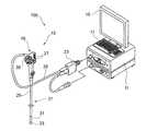
図1は本発明の実施形態を説明するための図で、内視鏡装置の構成を概略的に示すブロック図であり、図2は内視鏡装置の具体的な構成例を示す外観図である。
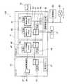
内視鏡装置100は、図1に示すように、プロセッサ11と、プロセッサ11に接続された内視鏡スコープ13と、観察画像等の情報を表示するモニタ15と、プロセッサ11に接続されたキーボード等の入力部17とを有する。Hereinafter, embodiments of the present invention will be described in detail with reference to the drawings.
FIG. 1 is a diagram for explaining an embodiment of the present invention, and is a block diagram schematically showing a configuration of an endoscope apparatus. FIG. 2 is an external view showing a specific configuration example of the endoscope apparatus. is there.
As shown in FIG. 1, the
図2に示すように、内視鏡スコープ13は、本体操作部19と、この本体操作部19に連設され被検体(体腔)内に挿入される挿入部21と、本体操作部19から延設され先端にコネクタ23が設けられたユニバーサルコード25とを備える。ユニバーサルコード先端のコネクタ23は、プロセッサ11に着脱自在に接続されて、各種信号が入出力される。 As shown in FIG. 2, the
本体操作部19には、挿入部21の先端側で吸引、送気、送水を実施するための送気送水ボタン、撮像時のシャッターボタン等の各種操作ボタン27や、アングルノブ35等が設けられている。 The main
挿入部21は、本体操作部19側から順に軟性部29、湾曲部31、内視鏡先端部33で構成される。湾曲部31は、本体操作部19のアングルノブ35を回転することによって遠隔的に湾曲操作され、これにより内視鏡先端部33を所望の方向に向けることができる。 The
内視鏡先端部33には、撮像光学系の観察窓が配置される。観察窓の内部には、CCD(Charge Coupled Device)型イメージセンサや、CMOS(Complementary Metal Oxide Semiconductor)型イメージセンサ等の撮像素子37と、観察画を撮像素子37に結像させるレンズ39とが配置される。 An observation window of the imaging optical system is disposed at the endoscope
上記構成の内視鏡装置100は、複数の電子デバイスのプログラムモジュールを、準備された更新用プログラムにより書き換え、この書き換えたプログラムモジュールに対する制御パラメータを所望の値に設定する機能を有する。 The
<プログラムモジュールの更新>
図1に示すように、内視鏡スコープ13には、所望の観察画像を得るための撮像素子37、操作ボタン27等が設けられ、操作ボタン27からの入力信号を受け付けるCPU3等の電子デバイスを有する。CPU3はROM41を備え、このROM41には、CPU3を動作させるファームウェアとしてのプログラムモジュールが格納される。<Updating program modules>
As shown in FIG. 1, the
プロセッサ11における撮像光学系と関係する回路は、回路基板S1、回路基板S2、及び回路基板S2に接続される更新情報入力部43とを有して構成される。 The circuit related to the imaging optical system in the
回路基板S1は、駆動信号を撮像素子37に出力するセンサ駆動FPGA(Field-Programmable Gate Array)45と、センサ駆動FPGA45を制御するCPU1が実装されている。センサ駆動FPGA45はプログラムモジュールを格納するROM47を備え、CPU1もプログラムモジュールを格納するROM49を備える。FPGAは、プログラムモジュールを読み込むことにより論理回路の書き換えが可能なプログラマブル集積回路であり、CPUは、論理回路の書き換えが不可能な非プログラマブル集積回路である。 The circuit board S1 is mounted with a sensor-driven FPGA (Field-Programmable Gate Array) 45 that outputs a drive signal to the
CPU1は、内視鏡スコープ13側のCPU3にユニバーサルコード25(図2参照)を通じてシリアル接続されており、センサ駆動FPGA45とは同一の回路基板内でパラレル接続されている。また、CPU1は回路基板S2に実装されたCPU2とパラレル接続されている。CPU1は、センサ駆動FPGA45に撮像素子37への制御信号を出力すると共に、操作ボタン27からの入力による制御信号が入力される。 The
回路基板S2は、内視鏡を統括制御するプロセッサ11のメインCPUであるCPU2と、映像入力FPGA51と、画像処理FPGA53と、記憶手段であるメモリ55が実装されている。CPU2はROM57、映像入力FPGA51はROM59、画像処理FPGA53はROM61、をそれぞれ備え、それぞれのROMにそれぞれのプログラムモジュールが格納される。メモリ55には、外部より入力され、複数の電子デバイスそれぞれに対する新バージョンのプログラムモジュールの情報を含む更新用プログラムが記憶される。 The circuit board S2 is mounted with a
CPU2は、上記プロセッサ11、内視鏡スコープ13に搭載される複数のCPU、FPGAを制御する。このCPU2は、内視鏡装置100の操作者による操作に応じて、所望の内視鏡観察画像をモニタ15に出力させる。各CPU,FPGAが備えるROMには、それぞれデバイスに対応するプログラムモジュールが格納されており、入力された命令信号に応じて所望の機能を実現するようになっている。また、CPU2は、更新情報入力部43を通じて後述する記憶媒体63等から更新情報を読み出して、各電子デバイスのプログラムモジュールを更新する。 The
次に、各電子デバイスのプログラムモジュールを、新たに供給される新バージョンのプログラムモジュールに更新する手順について説明する。
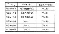
各電子デバイスのプログラムモジュールは、バージョン名で表されるバージョン情報に基づいて管理されている。これら各電子デバイスのプログラムモジュールのバージョンは、バージョン情報としてメモリ55に記憶されている。図3はバージョン情報の一例を示す。CPU2は、メモリ55からバージョン情報を参照することで、各電子デバイスに格納されたプログラムモジュールのバージョン、即ち、プログラムモジュールの機能や仕様を常に正確に把握できるようになっている。Next, a procedure for updating the program module of each electronic device to a new version of the program module to be newly supplied will be described.
The program module of each electronic device is managed based on version information represented by a version name. The version of the program module of each electronic device is stored in the
内視鏡装置100における各電子デバイスのプログラムモジュールを、新バージョンのプログラムモジュールに更新する場合、操作者は、プロセッサ11の更新情報入力部43に、コンパクトフラッシュ(登録商標)、SDカード等の各種メモリカードや、ハードディスク、光ディスク、磁気テープ等の各種ストレージ装置等の記憶媒体63を挿入する。そして、CPU2が記憶媒体63に記憶された更新情報を読み出し、この読み出された更新情報をメモリ55に一旦記憶させる。その後、CPU2は各電子デバイスのROMを必要に応じて書き替える。これにより、内視鏡装置100への新規機能の搭載や、不具合の解消が行える。なお、更新情報は、記憶媒体63に限らず、ネットワーク65を通じて配信する構成であってもよい。 When updating the program module of each electronic device in the
図4に更新情報の一例を示す。CPU2は、図3に示す現在のバージョン情報と、更新情報のバージョン情報とを比較して、バージョンナンバーが下位となる旧バージョンのプログラムモジュールを、上位となる新バージョンのプログラムモジュールに選択的に更新する。つまり、図5にバージョンアップの様子を示すように、CPU2は、更新情報であるバージョンアップキットに記憶された各プログラムモジュールのバージョンナンバーと、現在のバージョンナンバーとを比較して、現在のバージョンナンバーが低い場合に新バージョンのプログラムモジュールが提供されたと判定し、そのプログラムモジュールを新バージョンのプログラムモジュールに更新する。また、比較の結果、現在のバージョンナンバーと同じであった場合は、そのプログラムモジュール(図示例では存在せず)を更新せずに、そのままとする。 FIG. 4 shows an example of update information. The
次に、各プログラムモジュールのバージョンアップを行う順序の決定方法について説明する。
旧バージョンのプログラムモジュールを新バージョンのプログラムモジュールに更新する場合、内視鏡装置100に搭載されたCPU、FPGAのそれぞれに対して、個別にプログラムモジュールを更新する必要がある。しかし、実際に使用されている内視鏡装置の機器構成は、内視鏡スコープやプロセッサの種類が多種多様であり、組み合わせによって回路構成が異なれば、更新するプログラムモジュールの格納箇所も異なる。そのため、機器のメーカ側から更新情報が提供されても、各内視鏡装置に対して一律に更新順序を設定することはできない。つまり、内視鏡装置毎に異なる更新順序を設定する必要がある。Next, a method for determining the order in which the program modules are upgraded will be described.
When an old version of a program module is updated to a new version of a program module, it is necessary to update the program module individually for each of the CPU and FPGA mounted on the
具体的には、追加機能に関しては、プログラムモジュールを呼び出す側と、呼び出される側とでは更新順序の制約がある。例えば、基板上にCPUとFPGAが実装され、CPUがFPGAを制御する構成において、新規機能としてI/Fが増加する場合、FPGAのプログラムモジュールを先に更新してからCPUのプログラムモジュールを更新する必要がある。逆の手順で更新した場合には、CPUは、搭載していないI/FでFPGAを制御する動作となり、予期しない不具合が起きる可能性がある。 Specifically, with regard to the additional function, there is a restriction on the update order between the side that calls the program module and the side that is called. For example, in a configuration in which a CPU and an FPGA are mounted on a board and the CPU controls the FPGA, when the I / F increases as a new function, the FPGA program module is updated first, and then the CPU program module is updated. There is a need. When updated in the reverse procedure, the CPU operates to control the FPGA with an unmounted I / F, and an unexpected malfunction may occur.
更に、FPGAはコンフィグレーション後に動作するものであるため、バージョンアップを行う際は、プログラムモジュールの書き換え後にコンフィグレーションを実施する必要がある。CPUの場合は、書き換え対象CPUのプログラムモジュールが更新後に参照できなくなるため、プログラムモジュールを他のRAM上に一旦退避させてから書き換え等の動作を行う必要があり、リセットやリブート処理を要する。 Furthermore, since the FPGA operates after configuration, when upgrading, it is necessary to perform configuration after rewriting the program module. In the case of the CPU, since the program module of the CPU to be rewritten cannot be referred to after updating, it is necessary to perform operations such as rewriting after temporarily saving the program module in another RAM, and reset and reboot processing are required.
そのため、プログラムモジュールのバージョンアップを行う際は、変更が必要となるプログラムモジュールを特定し、この特定された各プログラムモジュールの主従関係や、リブートの有無等を加味して更新順序を決定することが必要となる。 Therefore, when upgrading a program module, it is possible to identify the program module that needs to be changed, and determine the update order in consideration of the master-slave relationship of each identified program module, the presence or absence of reboot, etc. Necessary.
本内視鏡装置100においては、プログラムモジュールの適切な更新順序を自動的に設定し、設定された更新順序で更新処理を実行する。以下に、プログラムモジュールのバージョンアップを行う手順を図6に示すフローチャートを用いて詳細に説明する。 In the
まず、内視鏡装置100の操作者は、記憶媒体63やネットワーク65を介して更新情報を更新情報入力部43に入力する(St.1)。CPU2は、更新情報入力部43に更新情報が入力されると、この更新情報をメモリ55に取り込む。 First, the operator of the
CPU2は、メモリ55に予め記憶された現在の各プログラムモジュールのバージョン情報(図3参照)と、更新情報のバージョン情報(図4参照)とを比較して、前述したように更新対象となる電子デバイスのプログラムモジュールを特定する(St.2)。図3,図4に示す情報内容の場合、更新対象となるプログラムモジュールは、モジュール1〜6であるが、更新しないプログラムモジュールが混在する場合は、更新しないプログラムモジュールを更新対象から外せばよい。 The
次に、特定された更新対象のプログラムモジュールを、内視鏡装置100の機器構成に応じてグループ分けする。グループ分けは、次のルールに従って行う。 Next, the identified program modules to be updated are grouped according to the device configuration of the
(A1)更新の際にコンフィグレーションを実施するFPGA等のプログラマブル集積回路を同一グループとする。
このルールによれば、センサ駆動FPGA45、映像入力FPGA51、画像処理FPGA53が同一グループとなる。このグループをグループAとする。(A1) Programmable integrated circuits such as FPGAs that perform configuration at the time of updating are grouped together.
According to this rule, the
(A2)システム全体を統括制御する非プログラマブル集積回路(ここではCPU2)と、このCPU2とパラレル接続されるプログラマブル集積回路以外の電子デバイスを同一グループとする。
このルールによれば、CPU2とパラレル接続される電子デバイスとして、センサ駆動FPGA45,映像入力FPGA51,画像処理FPGA53,CPU1が同一のグループ候補として挙げられるが、センサ駆動FPGA45,映像入力FPGA51,画像処理FPGA53は除外する。その結果、CPU1とCPU2が同一グループとなる。このグループをグループBとする。(A2) A non-programmable integrated circuit (
According to this rule, the
そして、CPU3はCPU1とシリアル接続されており、CPU2に対してはパラレル接続されていない。よって、残りの電子デバイスであるCPU3をグループCとする。 The
上記のグループ分け処理により、図7に示すように更新対象となる電子デバイスは下記の3つのグループに分類される。
・グループA:センサ駆動FPGA45,映像入力FPGA51,画像処理FPGA53
・グループB:CPU1,CPU2
・グループC:CPU3By the above grouping process, as shown in FIG. 7, the electronic devices to be updated are classified into the following three groups.
Group A:
Group B: CPU1, CPU2
Group C: CPU3
次に、グループ分けされた各電子デバイスに対して、プログラムモジュールの更新順序を設定する(St.3)。
CPU2は、各グループ内に複数の電子デバイスが存在する場合に、各電子デバイスのグループ内更新順序を設定する。
グループ内の更新順序は、次のルールに従って設定する。
(B1)単独で内部リセット可能なCPUを、リブートが必要なCPUより先の更新順序に設定する。
つまり、グループBにおいては、CPU2とは異なる基板に実装されて、単独で内部リセット可能なCPU1を、回路全体のリブートが必要なCPU2より先の更新順序に設定する。これにより、リブートの回数を最小化でき、更新時間を短縮化できる。Next, the update order of the program modules is set for each grouped electronic device (St. 3).
When there are a plurality of electronic devices in each group, the
The update order within the group is set according to the following rules.
(B1) A CPU that can be internally reset independently is set in an update order before a CPU that needs to be rebooted.
That is, in the group B, the
グループAにおいては、特に更新順序を規定されることはない。ここでは映像信号の伝送下流側から、画像処理FPGA53,映像入力FPGA51,センサ駆動FPGA45の順番に設定しているが、それぞれの更新は同時であってもよい。 In group A, the update order is not particularly specified. Here, the
次に、CPU2は、各グループ間でグループ単位の更新順序を設定する。
グループ単位の更新順序は、次のルールに従って設定する。
(C1)プログラマブル集積回路(FPGA)に対しては、FPGAに命令信号を入力する非プログラマブル集積回路(CPU)より先の更新順序に設定する。
つまり、グループAを、グループB,Cより先の更新順序に設定する。Next, the
The update order for each group is set according to the following rules.
(C1) For the programmable integrated circuit (FPGA), the update order is set before the non-programmable integrated circuit (CPU) that inputs a command signal to the FPGA.
That is, group A is set in an update order prior to groups B and C.
(C2)システム全体を統括制御する非プログラマブル集積回路(ここではCPU2)とは異なるグループの非プログラマブル集積回路(CPU)は、更新にリブートを要するので、統括制御する非プログラマブル集積回路(ここではCPU2)のグループを、異なるグループの非プログラマブル集積回路(CPU)より先の更新順序に設定する。
つまり、CPU2を含むグループBは、グループBとは異なりCPU3を含むグループCより先の更新順序に設定する。(C2) A non-programmable integrated circuit (CPU) in a group different from the non-programmable integrated circuit (here CPU2) that performs overall control of the entire system requires a reboot for updating. ) Are set in an update order prior to a different group of non-programmable integrated circuits (CPUs).
That is, the group B including the
(C3)次の更新対象となる電子デバイスのグループが、当該グループの前の更新対象である電子デバイスのグループと異なる場合に、グループ同士の間にリブートを設定する。(C3) If the group of electronic devices to be updated next is different from the group of electronic devices to be updated before the group, reboot is set between the groups.
以上より、各電子デバイスのプログラムモジュールの更新順序は次の通りになる。なお、リブート処理は、グループ内全ての書き込みの必要がない場合には省略する。 From the above, the update order of the program modules of each electronic device is as follows. The reboot process is omitted when it is not necessary to write all the data in the group.
(1)グループA:画像処理FPGA53
(2)グループA:映像入力FPGA51
(3)グループA:センサ駆動FPGA45
−リブート−
(4)グループB:CPU1
(5)グループB:CPU2
−リブート−
(6)グループC:CPU3(1) Group A:
(2) Group A:
(3) Group A:
-Reboot-
(4) Group B: CPU1
(5) Group B: CPU2
-Reboot-
(6) Group C: CPU3
内視鏡装置100は、図7に示すグループ内更新順序、グループ単位更新順序の登録された更新順序テーブルであるルックアップテーブルLUTをメモリ55に保存し、このLUTの順序に従ってプログラムモジュールを更新する。 The
そして、CPU2は、設定した更新順序をモニタ15に出力して、内視鏡装置100の操作者に通知する。これにより、操作者へのガイダンスが行われる(St.4)。操作者はモニタ15に表示されたガイダンスに従って、バージョンアップ処理を開始する(St.5)。このバージョンアップ処理は、自動で実施することが望ましいが、ステップ毎に手動で実施して、逐次確認しながら実施することであってもよい。 Then, the
例えば、CPU2は、更新するプログラムモジュールをモニタ15にリスト表示させ、操作者に書き換え開始の指示を入力させる。開始指示が入力されると、CPU2はプログラムモジュールの書き換えを開始すると共に、現在どのプログラムモジュールの書き換えを実施しているのかをモニタ表示色を変化させる等、視覚的に判別できるようにする。一つのプログラムモジュールの書き換えが完了すると一時停止し、操作者からの開始指示待ちにして、開始指示の入力があったときに、次のプログラムモジュールの書き換えを開始する。 For example, the
<制御パラメータの設定>
次に、プログラムモジュールの書き換え後、更新されたプログラムモジュールで使用される制御パラメータを設定することについて説明する。
St.5でプログラムモジュールの更新を完了させた後、CPU2は、更新内容の確認画面をモニタ15に表示する(St.6)。この更新内容の確認画面を図8に示した。<Control parameter setting>
Next, setting of control parameters used in the updated program module after rewriting the program module will be described.
St. After completing the update of the program module in step 5, the
更新情報入力部43に入力された更新情報は、更新プログラムであり、新バージョンのプログラムモジュールの情報が含まれる。これらを総称してファームウェアVer.***等と確認画面71に表示される。また、確認画面71には、内視鏡装置100に搭載された電子デバイスの名称と、プログラムモジュール更新後に各電子デバイスに格納されたプログラムモジュールのバージョンナンバーとが表示される。 The update information input to the update
上述したプログラムモジュールの更新においては、PFGA1〜3,CPU1〜3の各プログラムモジュールを更新したが、例えば、FPGA3とCPU2のプログラムモジュールのみ更新した場合には、確認画面71にはこれら更新された電子デバイスの表示部分73だけが強調される。更新のあった電子デバイスのみ強調表示することで、操作者はどの電子デバイスに対してプログラムモジュールが更新されたのかを容易に判断できる。 In the update of the program modules described above, the program modules of
また、図9に示すように、更新のあった電子デバイスのみを確認画面71に表示するようにしてもよい。この場合には、特に電子デバイスが多数存在する場合に、どの電子デバイスに対して更新されたかが、より明確となる。 Further, as shown in FIG. 9, only the updated electronic device may be displayed on the
操作者が、マウスやキーボード等の入力部17(図1参照)の操作により、確認画面71内の次画面への移動ボタン75を押下すると、CPU2は、図10に示す新機能の説明画面77をモニタ15に表示する。新機能の説明画面77には、プログラムモジュールに新たに追加された機能の説明がされている。操作者は、この機能説明の表示によって、追加機能の内容と、制御パラメータの設定値の内容とを確認することができる。 When the operator depresses a
プログラムモジュールの更新により、制御パラメータを新たに設定する必要がある場合(St.7)は、説明画面77に設定値入力ボタン79が表示される。操作者が、この設定値入力ボタン79を押下すると、設定値の入力を行う画面が表示され、ここで設定値を入力する(St.8)。制御パラメータを設定する必要がない場合は、内視鏡装置100への更新処理を終了する。 When the control parameter needs to be newly set by updating the program module (St. 7), a set
設定値の入力を行う場合、操作者が新機能の説明画面77の設定値入力ボタン79を押下すると、CPU2は、図11に示す新機能の設定値入画面をモニタ15に表示する。新機能の設定値入力画面81は、観察画像を表示する画像表示領域83と、新機能の制御パラメータを設定する制御パラメータ設定領域85と、操作説明領域87とを有する。画像表示領域83に表示する観察画像は、過去に撮影された観察画像データや、標準的な標準画像データ等を予めメモリ55に記憶させておき、これら画像データを適宜選択的に表示用画像として用いる。 When the setting value is input, when the operator presses the setting
制御パラメータ設定領域85には、コントラスト強調のための設定値、ハレーション低減のための設定値、照明光量設定のための設定値が表示される。これらの設定値を設定するには、上下キーやマウス操作により項目選択を行い、選択された項目に対して予め用意された設定値を左右キーやマウス操作により選択する。図示例では、「ハレーション低減」を選択項目89とし、「−3」の設定値91が設定された状態を示す。 The control
制御パラメータ設定領域85から設定値が入力されると、CPU2は、その設定値に基づいてプログラムモジュールを動作させた結果としての処理画像を画像表示領域83にリアルタイムで表示する。照明光量の設定値に関しては、撮像画像に対する後処理ではないため、予め設定値毎に設定された補正テーブルを参照して推定により処理画像を生成する。なお、場合によっては内視鏡装置100の照明光学系を、入力された制御パラメータに基づき駆動して、実際の観察画像を撮像光学系から取得し、この観察画像を画像表示領域83に表示するようにしてもよい。 When a setting value is input from the control
このように、設定された評価パラメータに基づいてプログラムモジュールを実行させ、その実行結果の画像情報を画像表示領域83にリアルタイムで表示することで、操作者は、設定した評価パラメータの効果の度合いを確認できる。そのため、操作者は設定値の効果を確認しながら、評価パラメータを適正なレベルに合わせることができる。 Thus, the program module is executed based on the set evaluation parameter, and the image information of the execution result is displayed in real time in the
以上説明した内視鏡装置100によれば、プログラムモジュールの更新を行った後、更新されたプログラムモジュールの情報をモニタ15に表示するため、操作者は、更新対象となったプログラムモジュールと、その変更内容とを容易に確認できる。また、新たに追加、変更された機能に対する制御パラメータを設定する必要がある場合、プログラムモジュールの更新処理に続けてこれを設定できる。つまり、プログラムモジュールの更新後、内視鏡装置100を次回起動するまでの間に、制御パラメータの設定値を入力しておくことで、内視鏡装置100の次回起動時には、新たに制御パラメータを入力する必要がなくなる。その結果、操作者は、内視鏡装置100を用いた通常の作業を中断することなく、効率良く円滑に実施できる。 According to the
また、内視鏡装置100は、プログラムモジュールを更新する際、更新が必要となる電子デバイスを、内視鏡装置100の機器構成に応じてグループ分けし、予め定めたルールに従って、グループ単位の更新順序と、同一グループ内における更新順序とを設定し、各プログラムモジュールの最適な更新順序を決定する。このため、他の異なる種類の内視鏡スコープ13に付け替えたり、プロセッサ11を入れ替えたりする等、内視鏡装置100の電子デバイス構成に変更が生じても、変更後の機器構成に対する最適な更新順序に設定することができる。 In addition, when updating the program module, the
そのため、内視鏡装置100の操作者は、プログラムモジュールの更新の際、装置構成に応じた更新手順の検討を要することなく、内視鏡装置100が自動的に決定した最適な更新順序でバージョンアップが行える。また、更新処理の所要時間を短縮でき、誤った操作手順で更新されることも未然に防止できる。 Therefore, the operator of the
本発明は上記の実施形態に限定されるものではなく、実施形態の各構成を相互に組み合わせることや、明細書の記載、並びに周知の技術に基づいて、当業者が変更、応用することも本発明の予定するところであり、保護を求める範囲に含まれる。 The present invention is not limited to the above-described embodiments, and the configurations of the embodiments may be combined with each other, or may be modified or applied by those skilled in the art based on the description of the specification and well-known techniques. The invention is intended and is within the scope of seeking protection.
以上の通り、本明細書には次の事項が開示されている。
(1) プログラムモジュールによって制御される電子デバイスを複数含み、当該複数の電子デバイスのプログラムモジュールを更新する機能を有する電子機器であって、
外部より入力される前記複数の電子デバイスに対応する更新用プログラムを記憶する記憶手段と、
更新対象となる前記電子デバイスのプログラムモジュールを前記記憶手段に記憶されている更新用プログラムにより更新する更新実行手段と、
前記更新されたプログラムモジュールの制御パラメータを入力する入力手段と、
前記更新実行手段による前記プログラムモジュールの更新後、前記電子機器を次回起動するまでの間に、前記更新された電子デバイスに対して、前記入力手段から入力された制御パラメータを設定する制御パラメータ設定手段と、
を備えた電子機器。
この電子機器によれば、プログラムモジュールを更新した後に、このプログラムモジュールに使用される制御パラメータを更新作業に続けて設定することで、作業効率を高めて円滑に更新作業と設定作業を実施でき、電子機器の使用時において、煩わしい制御パラメータの設定作業を生じさせることがなくなる。As described above, the following items are disclosed in this specification.
(1) An electronic apparatus including a plurality of electronic devices controlled by a program module, and having a function of updating a program module of the plurality of electronic devices,
Storage means for storing an update program corresponding to the plurality of electronic devices input from the outside;
Update execution means for updating a program module of the electronic device to be updated by an update program stored in the storage means;
Input means for inputting control parameters of the updated program module;
Control parameter setting means for setting a control parameter input from the input means for the updated electronic device after the update of the program module by the update execution means and before starting the electronic device next time When,
With electronic equipment.
According to this electronic device, after updating the program module, by setting the control parameters used for the program module following the update work, the work efficiency can be improved and the update work and the setting work can be performed smoothly. When an electronic device is used, troublesome control parameter setting work is not caused.
(2) (1)の電子機器であって、
情報を表示する表示手段を備え、
前記制御パラメータ設定手段は、設定された前記制御パラメータに基づいて前記更新されたプログラムモジュールを実行させた結果の情報を、前記表示手段に表示させる機能を有する電子機器。
この電子機器によれば、指定された制御パラメータの設定値による実行結果の情報が表示手段に表示されるので、操作者がこの表示内容を確認しながら制御パラメータの設定値を適切に調節することができる。(2) The electronic device according to (1),
A display means for displaying information;
The control parameter setting unit is an electronic device having a function of causing the display unit to display information on a result of executing the updated program module based on the set control parameter.
According to this electronic apparatus, the execution result information according to the set value of the designated control parameter is displayed on the display means, so that the operator can appropriately adjust the set value of the control parameter while checking the display content. Can do.
(3) (2)の電子機器であって、
該電子機器は、光源からの光を照射する照明光学系と、撮像素子により撮像画像を生成する撮像光学系とを有し、
前記制御パラメータは、前記光源の制御パラメータ、前記撮像画像に対する画像処理パラメータの少なくともいずれかを含む電子機器。
この電子機器によれば、光源の制御パラメータや画像処理パラメータが適切に調節されることで、高品位な撮像画像の情報を得ることができる。(3) The electronic device of (2),
The electronic apparatus includes an illumination optical system that irradiates light from a light source, and an imaging optical system that generates a captured image using an imaging element.
The electronic device includes at least one of a control parameter of the light source and an image processing parameter for the captured image.
According to this electronic apparatus, high-quality captured image information can be obtained by appropriately adjusting the light source control parameters and the image processing parameters.
(4) (2)又は(3)の電子機器であって、
前記更新実行手段は、前記プログラムモジュールの更新後、前記複数のプログラムモジュールのうち、更新されたプログラムモジュールの情報を、更新されないプログラムモジュールの情報と区別して前記表示手段に表示させる電子機器。
この電子機器によれば、操作者が、どの電子デバイスに対してプログラムモジュールが更新されたのかを容易に判断できる。(4) The electronic device of (2) or (3),
The update execution unit is an electronic device that, after updating the program module, causes the display unit to display information on an updated program module among the plurality of program modules separately from information on a program module that is not updated.
According to this electronic apparatus, the operator can easily determine to which electronic device the program module has been updated.
(5) (4)の電子機器であって、
前記更新実行手段は、前記更新されたプログラムモジュールの更新前からの変更内容を、前記表示手段に表示させる電子機器。
この電子機器によれば、操作者が、この変更内容の表示によって、例えば追加機能の内容や制御パラメータの設定値の内容等を容易に確認することができる。(5) The electronic device according to (4),
The update execution means is an electronic device that causes the display means to display the changed contents of the updated program module from before the update.
According to this electronic device, the operator can easily confirm, for example, the content of the additional function and the content of the set value of the control parameter by displaying the change content.
(6) (4)の電子機器であって、
前記更新手段は、前記更新されたプログラムモジュールに関する情報のみを前記表示手段に表示させる電子機器。
この電子機器によれば、特に電子デバイスが多数存在する場合に、どの電子デバイスに対して更新されたかが、より明確となる。(6) The electronic device according to (4),
The update means is an electronic device that causes the display means to display only information relating to the updated program module.
According to this electronic apparatus, particularly when there are a large number of electronic devices, it becomes clearer which electronic device has been updated.
(7) (1)〜(6)のいずれか一つの電子機器を備えた内視鏡装置。
この内視鏡装置によれば、プログラムモジュールが更新された後に、続けて制御パラメータの設定値を入力できるので、効率良く制御パラメータを設定できる。(7) An endoscope apparatus including any one of the electronic devices according to (1) to (6).
According to this endoscope apparatus, since the set value of the control parameter can be input continuously after the program module is updated, the control parameter can be set efficiently.
(8) プログラムモジュールによって制御される電子デバイスを複数含む電子機器の、当該複数の電子デバイスのプログラムモジュールを更新するプログラムモジュール更新方法であって、
外部より入力される前記複数の電子デバイスに対応する更新用プログラムを記憶手段に記憶させるステップと、
更新対象となる前記電子デバイスに対して、該電子デバイスのプログラムモジュールを前記記憶手段に記憶された更新用プログラムにより更新するステップと、
前記更新されたプログラムモジュールの制御パラメータを入力するステップと、
前記更新実行手段による前記プログラムモジュールの更新後、前記電子機器を次回起動するまでの間に、前記更新された電子デバイスに対して、前記入力された制御パラメータを設定するステップと、
を含むプログラムモジュール更新方法。
このプログラムモジュール更新方法によれば、プログラムモジュールを更新した後に、このプログラムモジュールに使用される制御パラメータを更新作業に続けて設定することで、作業効率を高めて円滑に更新作業と設定作業を実施でき、電子機器の使用時において、煩わしい制御パラメータの設定作業を生じさせることがなくなる。(8) A program module update method for updating a program module of a plurality of electronic devices of an electronic apparatus including a plurality of electronic devices controlled by the program module,
Storing an update program corresponding to the plurality of electronic devices input from the outside in a storage unit;
Updating the electronic device program module with the update program stored in the storage means for the electronic device to be updated;
Inputting control parameters of the updated program module;
Setting the input control parameters for the updated electronic device after the update of the program module by the update execution means and before starting the electronic device next time;
Program module update method including:
According to this program module update method, after updating the program module, the control parameters used for this program module are set after the update work, thereby improving the work efficiency and smoothly performing the update work and the setting work. This eliminates troublesome control parameter setting work when the electronic apparatus is used.
11 プロセッサ
13 内視鏡スコープ
15 モニタ
17 入力部
37 撮像素子
41 ROM
43 更新情報入力部
45 センサ駆動FPGA
47 ROM
49 ROM
51 映像入力FPGA
53 画像処理FPGA
55 メモリ
57 ROM
59 ROM
61 ROM
63 記憶媒体
71 確認画面
73 電子デバイスの表示部分
77 新機能の説明画面
81 新機能の設定値入力画面
83 画像表示領域
85 制御パラメータ設定領域
100 内視鏡装置11
43 Update
47 ROM
49 ROM
51 Video input FPGA
53 Image processing FPGA
55
59 ROM
61 ROM
63
Claims (8)
Translated fromJapanese外部より入力される前記複数の電子デバイスに対応する更新用プログラムを記憶する記憶手段と、
更新対象となる前記電子デバイスのプログラムモジュールを前記記憶手段に記憶されている更新用プログラムにより更新する更新実行手段と、
前記更新されたプログラムモジュールの制御パラメータを入力する入力手段と、
前記更新実行手段による前記プログラムモジュールの更新後、前記電子機器を次回起動するまでの間に、前記更新された電子デバイスに対して、前記入力手段から入力された制御パラメータを設定する制御パラメータ設定手段と、
を備えた電子機器。An electronic apparatus including a plurality of electronic devices controlled by a program module, and having a function of updating a program module of the plurality of electronic devices,
Storage means for storing an update program corresponding to the plurality of electronic devices input from the outside;
Update execution means for updating a program module of the electronic device to be updated by an update program stored in the storage means;
Input means for inputting control parameters of the updated program module;
Control parameter setting means for setting a control parameter input from the input means for the updated electronic device after the update of the program module by the update execution means and before starting the electronic device next time When,
With electronic equipment.
情報を表示する表示手段を備え、
前記制御パラメータ設定手段は、設定された前記制御パラメータに基づいて前記更新されたプログラムモジュールを実行させた結果の情報を、前記表示手段に表示させる機能を有する電子機器。The electronic device according to claim 1,
A display means for displaying information;
The control parameter setting unit is an electronic device having a function of causing the display unit to display information on a result of executing the updated program module based on the set control parameter.
該電子機器は、光源からの光を照射する照明光学系と、撮像素子により撮像画像を生成する撮像光学系とを有し、
前記制御パラメータは、前記光源の制御パラメータ、前記撮像画像に対する画像処理パラメータの少なくともいずれかを含む電子機器。The electronic device according to claim 2,
The electronic apparatus includes an illumination optical system that irradiates light from a light source, and an imaging optical system that generates a captured image using an imaging element.
The electronic device includes at least one of a control parameter of the light source and an image processing parameter for the captured image.
前記更新実行手段は、前記プログラムモジュールの更新後、前記複数のプログラムモジュールのうち、更新されたプログラムモジュールの情報を、更新されないプログラムモジュールの情報と区別して前記表示手段に表示させる電子機器。An electronic device according to claim 2 or claim 3,
The update execution unit is an electronic device that, after updating the program module, causes the display unit to display information on an updated program module among the plurality of program modules separately from information on a program module that is not updated.
前記更新実行手段は、前記更新されたプログラムモジュールの更新前からの変更内容を、前記表示手段に表示させる電子機器。The electronic device according to claim 4,
The update execution means is an electronic device that causes the display means to display the changed contents of the updated program module from before the update.
前記更新手段は、前記更新されたプログラムモジュールに関する情報のみを前記表示手段に表示させる電子機器。The electronic device according to claim 4,
The update means is an electronic device that causes the display means to display only information relating to the updated program module.
外部より入力される前記複数の電子デバイスに対応する更新用プログラムを記憶手段に記憶させるステップと、
更新対象となる前記電子デバイスに対して、該電子デバイスのプログラムモジュールを前記記憶手段に記憶された更新用プログラムにより更新するステップと、
前記更新されたプログラムモジュールの制御パラメータを入力するステップと、
前記更新実行手段による前記プログラムモジュールの更新後、前記電子機器を次回起動するまでの間に、前記更新された電子デバイスに対して、前記入力された制御パラメータを設定するステップと、
を含むプログラムモジュール更新方法。A program module update method for updating a program module of a plurality of electronic devices of an electronic apparatus including a plurality of electronic devices controlled by the program module,
Storing an update program corresponding to the plurality of electronic devices input from the outside in a storage unit;
Updating the electronic device program module with the update program stored in the storage means for the electronic device to be updated;
Inputting control parameters of the updated program module;
Setting the input control parameters for the updated electronic device after the update of the program module by the update execution means and before starting the electronic device next time;
Program module update method including:
Priority Applications (1)
| Application Number | Priority Date | Filing Date | Title |
|---|---|---|---|
| JP2011119636AJP2012248031A (en) | 2011-05-27 | 2011-05-27 | Electronic apparatus, endoscopic device, and program module update method of electronic apparatus |
Applications Claiming Priority (1)
| Application Number | Priority Date | Filing Date | Title |
|---|---|---|---|
| JP2011119636AJP2012248031A (en) | 2011-05-27 | 2011-05-27 | Electronic apparatus, endoscopic device, and program module update method of electronic apparatus |
Publications (2)
| Publication Number | Publication Date |
|---|---|
| JP2012248031Atrue JP2012248031A (en) | 2012-12-13 |
| JP2012248031A5 JP2012248031A5 (en) | 2014-01-16 |
Family
ID=47468412
Family Applications (1)
| Application Number | Title | Priority Date | Filing Date |
|---|---|---|---|
| JP2011119636AAbandonedJP2012248031A (en) | 2011-05-27 | 2011-05-27 | Electronic apparatus, endoscopic device, and program module update method of electronic apparatus |
Country Status (1)
| Country | Link |
|---|---|
| JP (1) | JP2012248031A (en) |
Cited By (8)
| Publication number | Priority date | Publication date | Assignee | Title |
|---|---|---|---|---|
| JP2014147464A (en)* | 2013-01-31 | 2014-08-21 | Hoya Corp | Endoscope apparatus |
| JP2016077432A (en)* | 2014-10-14 | 2016-05-16 | オリンパス株式会社 | Processor and endoscope system |
| JP2017144250A (en)* | 2014-12-26 | 2017-08-24 | オリンパス株式会社 | Endoscope system |
| JP2017200596A (en)* | 2017-06-28 | 2017-11-09 | Hoya株式会社 | Endoscope device |
| WO2017221738A1 (en)* | 2016-06-23 | 2017-12-28 | オリンパス株式会社 | Image processing device |
| CN113812905A (en)* | 2020-06-19 | 2021-12-21 | 深圳迈瑞生物医疗电子股份有限公司 | Endoscope camera shooting host, control method, system and storage medium |
| JP2022093548A (en)* | 2014-07-28 | 2022-06-23 | イリノイ トゥール ワークス インコーポレイティド | Real-time video growth meter |
| CN111565655B (en)* | 2017-10-30 | 2023-10-24 | 爱惜康有限责任公司 | Control system arrangement for modular surgical instrument |
Citations (3)
| Publication number | Priority date | Publication date | Assignee | Title |
|---|---|---|---|---|
| JPH11146078A (en)* | 1997-11-06 | 1999-05-28 | Murata Mach Ltd | Communication system and communication terminal device |
| JP2009100326A (en)* | 2007-10-18 | 2009-05-07 | Keyence Corp | High-speed photographic apparatus, control method for high-speed photographic apparatus and computer program |
| JP2010191786A (en)* | 2009-02-19 | 2010-09-02 | Fujitsu Ten Ltd | Onboard device |
- 2011
- 2011-05-27JPJP2011119636Apatent/JP2012248031A/ennot_activeAbandoned
Patent Citations (3)
| Publication number | Priority date | Publication date | Assignee | Title |
|---|---|---|---|---|
| JPH11146078A (en)* | 1997-11-06 | 1999-05-28 | Murata Mach Ltd | Communication system and communication terminal device |
| JP2009100326A (en)* | 2007-10-18 | 2009-05-07 | Keyence Corp | High-speed photographic apparatus, control method for high-speed photographic apparatus and computer program |
| JP2010191786A (en)* | 2009-02-19 | 2010-09-02 | Fujitsu Ten Ltd | Onboard device |
Cited By (11)
| Publication number | Priority date | Publication date | Assignee | Title |
|---|---|---|---|---|
| JP2014147464A (en)* | 2013-01-31 | 2014-08-21 | Hoya Corp | Endoscope apparatus |
| JP2022093548A (en)* | 2014-07-28 | 2022-06-23 | イリノイ トゥール ワークス インコーポレイティド | Real-time video growth meter |
| JP7470150B2 (en) | 2014-07-28 | 2024-04-17 | イリノイ トゥール ワークス インコーポレイティド | Real-time Video Extensometer |
| JP2016077432A (en)* | 2014-10-14 | 2016-05-16 | オリンパス株式会社 | Processor and endoscope system |
| JP2017144250A (en)* | 2014-12-26 | 2017-08-24 | オリンパス株式会社 | Endoscope system |
| US10575711B2 (en) | 2014-12-26 | 2020-03-03 | Olympus Corporation | Endoscopic system |
| WO2017221738A1 (en)* | 2016-06-23 | 2017-12-28 | オリンパス株式会社 | Image processing device |
| JPWO2017221738A1 (en)* | 2016-06-23 | 2018-06-28 | オリンパス株式会社 | Image processing device |
| JP2017200596A (en)* | 2017-06-28 | 2017-11-09 | Hoya株式会社 | Endoscope device |
| CN111565655B (en)* | 2017-10-30 | 2023-10-24 | 爱惜康有限责任公司 | Control system arrangement for modular surgical instrument |
| CN113812905A (en)* | 2020-06-19 | 2021-12-21 | 深圳迈瑞生物医疗电子股份有限公司 | Endoscope camera shooting host, control method, system and storage medium |
Similar Documents
| Publication | Publication Date | Title |
|---|---|---|
| JP2012248031A (en) | Electronic apparatus, endoscopic device, and program module update method of electronic apparatus | |
| US20110145804A1 (en) | Imaging system | |
| JP2008149027A (en) | Endoscope apparatus | |
| TW201525858A (en) | Baseboard management controller and method of load firmware thereof | |
| WO2017024652A1 (en) | Method for starting liquid crystal display | |
| WO2016121464A1 (en) | Signal processing device and endoscope system | |
| CN111510627B (en) | Camera starting method and device, terminal and readable storage medium | |
| JP5624943B2 (en) | Electronic device and method for updating program module of electronic device | |
| US20050093974A1 (en) | Endoscope processor | |
| JPWO2016174903A1 (en) | Signal processing apparatus and medical observation system | |
| US20140371533A1 (en) | Endoscope device and endoscope system | |
| TWI420389B (en) | Human machine interface device and interface integration method thereof | |
| JP5690656B2 (en) | Electronic device and method for updating program module of electronic device | |
| US8732823B2 (en) | Nondestructive testing system | |
| JP2009279060A (en) | Endoscope system | |
| JP2014050137A (en) | Inverter device | |
| JP5891095B2 (en) | Endoscope device | |
| CN118806211A (en) | Cold light source control method and endoscope equipment | |
| CN113647091B (en) | Method for debugging a Camera Control Unit (CCU) | |
| CN113812905A (en) | Endoscope camera shooting host, control method, system and storage medium | |
| CN114334117A (en) | Configuration method, device and medium for endoscope body configuration information | |
| JP7067869B2 (en) | Image processing systems, information processing equipment, information processing methods, and information processing programs | |
| EP1892618A2 (en) | Display apparatus and information update method therefor | |
| JP4104405B2 (en) | Endoscope device | |
| JP2018094312A (en) | Operation management method for endoscope apparatus, endoscope apparatus, and program |
Legal Events
| Date | Code | Title | Description |
|---|---|---|---|
| RD03 | Notification of appointment of power of attorney | Free format text:JAPANESE INTERMEDIATE CODE: A7423 Effective date:20121005 | |
| A521 | Written amendment | Free format text:JAPANESE INTERMEDIATE CODE: A523 Effective date:20131127 | |
| A621 | Written request for application examination | Free format text:JAPANESE INTERMEDIATE CODE: A621 Effective date:20131127 | |
| A977 | Report on retrieval | Free format text:JAPANESE INTERMEDIATE CODE: A971007 Effective date:20140611 | |
| A131 | Notification of reasons for refusal | Free format text:JAPANESE INTERMEDIATE CODE: A131 Effective date:20140617 | |
| A762 | Written abandonment of application | Free format text:JAPANESE INTERMEDIATE CODE: A762 Effective date:20140820 |