JP2012247725A - Display unit - Google Patents
Display unitDownload PDFInfo
- Publication number
- JP2012247725A JP2012247725AJP2011121351AJP2011121351AJP2012247725AJP 2012247725 AJP2012247725 AJP 2012247725AJP 2011121351 AJP2011121351 AJP 2011121351AJP 2011121351 AJP2011121351 AJP 2011121351AJP 2012247725 AJP2012247725 AJP 2012247725A
- Authority
- JP
- Japan
- Prior art keywords
- frame
- panel
- display
- display panel
- disposed
- Prior art date
- Legal status (The legal status is an assumption and is not a legal conclusion. Google has not performed a legal analysis and makes no representation as to the accuracy of the status listed.)
- Withdrawn
Links
Images


Classifications
- G—PHYSICS
- G06—COMPUTING OR CALCULATING; COUNTING
- G06F—ELECTRIC DIGITAL DATA PROCESSING
- G06F1/00—Details not covered by groups G06F3/00 - G06F13/00 and G06F21/00
- G06F1/16—Constructional details or arrangements
- G06F1/1601—Constructional details related to the housing of computer displays, e.g. of CRT monitors, of flat displays
- H—ELECTRICITY
- H01—ELECTRIC ELEMENTS
- H01J—ELECTRIC DISCHARGE TUBES OR DISCHARGE LAMPS
- H01J11/00—Gas-filled discharge tubes with alternating current induction of the discharge, e.g. alternating current plasma display panels [AC-PDP]; Gas-filled discharge tubes without any main electrode inside the vessel; Gas-filled discharge tubes with at least one main electrode outside the vessel
- H01J11/20—Constructional details
- H01J11/34—Vessels, containers or parts thereof, e.g. substrates
- H—ELECTRICITY
- H04—ELECTRIC COMMUNICATION TECHNIQUE
- H04N—PICTORIAL COMMUNICATION, e.g. TELEVISION
- H04N5/00—Details of television systems
- H04N5/64—Constructional details of receivers, e.g. cabinets or dust covers
Landscapes
- Engineering & Computer Science (AREA)
- Physics & Mathematics (AREA)
- General Engineering & Computer Science (AREA)
- Theoretical Computer Science (AREA)
- Multimedia (AREA)
- Signal Processing (AREA)
- Plasma & Fusion (AREA)
- Computer Hardware Design (AREA)
- Human Computer Interaction (AREA)
- General Physics & Mathematics (AREA)
- Devices For Indicating Variable Information By Combining Individual Elements (AREA)
Abstract
Description
Translated fromJapanese本発明は、薄型、軽量のプラズマディスプレイパネル(以下、パネルという)を表示デバイスとして用いたプラズマディスプレイ装置などの平面型のディスプレイ装置に関するものである。 The present invention relates to a flat display device such as a plasma display device using a thin and light plasma display panel (hereinafter referred to as a panel) as a display device.
このプラズマディスプレイ装置に用いられるパネルは、大別して、駆動的にはAC型とDC型があり、放電形式では面放電型と対向放電型の2種類があるが、高精細化、大画面化および製造の簡便性から、現状では、プラズマディスプレイ装置の主流は、3電極構造の面放電型のものである。 Panels used in this plasma display device are roughly classified into AC type and DC type in terms of driving, and there are two types of discharge types: surface discharge type and counter discharge type. Due to the simplicity of manufacturing, at present, the mainstream of plasma display devices is a surface discharge type having a three-electrode structure.
この面放電型のプラズマディスプレイパネル構造は、少なくとも前面側が透明な一対の基板を基板間に放電空間が形成されるように対向配置するとともに、前記放電空間を複数に仕切るための隔壁を基板に配置し、かつ前記隔壁により仕切られた放電空間で放電が発生するように基板に電極群を配置するとともに放電により発光する赤色、緑色、青色に発光する蛍光体を設けて複数の放電セルを構成したもので、放電により発生する波長の短い真空紫外光によって蛍光体を励起し、赤色、緑色、青色の放電セルからそれぞれ赤色、緑色、青色の可視光を発することによりカラー表示を行っている。 In this surface discharge type plasma display panel structure, at least a pair of substrates whose front sides are transparent are arranged to face each other so that a discharge space is formed between the substrates, and partition walls for dividing the discharge space into a plurality of substrates are arranged on the substrate. In addition, a plurality of discharge cells are configured by arranging an electrode group on the substrate so that a discharge is generated in the discharge space partitioned by the barrier ribs, and providing phosphors that emit red, green, and blue light emitted by the discharge. However, phosphors are excited by vacuum ultraviolet light having a short wavelength generated by discharge, and red, green, and blue visible light is emitted from red, green, and blue discharge cells, respectively, to perform color display.
このようなプラズマディスプレイ装置は、液晶パネルに比べて高速の表示が可能であり、視野角が広いこと、大型化が容易であること、自発光型であるため表示品質が高いことなどの理由から、フラットパネルディスプレイの中で最近特に注目を集めており、多くの人が集まる場所での表示装置や家庭で大画面の映像を楽しむための表示装置として各種の用途に使用されている。 Such a plasma display device can display at a higher speed than a liquid crystal panel, has a wide viewing angle, is easy to enlarge, and is self-luminous so that the display quality is high. Recently, the flat panel display has attracted particular attention and is used for various purposes as a display device in a place where many people gather and a display device for enjoying a large screen image at home.
このようなプラズマディスプレイ装置においては、ガラスが主材料のパネルをアルミニウムなどの金属製のシャーシ部材の前面側に保持させ、そのシャーシ部材の背面側にパネルを発光させるための駆動回路を構成する回路基板を配置することによりモジュールを構成している(特許文献1参照)。 In such a plasma display device, a circuit constituting a driving circuit for holding a panel made mainly of glass on the front side of a chassis member made of metal such as aluminum and causing the panel to emit light on the back side of the chassis member. A module is configured by arranging a substrate (see Patent Document 1).
本発明はこのような現状に鑑みなされたもので、安価でデザイン性の優れた外装キャビネットを備えたディスプレイ装置を提供することを目的とするものである。 The present invention has been made in view of such a current situation, and an object of the present invention is to provide a display device including an exterior cabinet that is inexpensive and excellent in design.
上記目的を達成するために本発明のディスプレイ装置は、表示パネルおよびこの表示パネルに画像を表示するための駆動回路を搭載した回路基板を備えた表示モジュールと、前記表示パネルの周縁部に配置される金属製のフレームと、前記表示モジュールを収容する外装キャビネットとを有し、前記外装キャビネットは、前記表示パネルの前面側に前記フレームを覆うように配置される飾りパネルと、前記表示モジュールの背面側を覆うバックカバーとを備え、かつ前記飾りパネルは、着色された光透過性の樹脂材料により構成するとともに、前記フレーム上に配置される部分に連続的に肉厚変化させた偏肉部を形成したことを特徴とする。 In order to achieve the above object, a display device of the present invention is disposed at a peripheral portion of a display module including a display panel and a circuit board on which a drive circuit for displaying an image on the display panel is mounted. A decorative frame arranged to cover the frame on the front side of the display panel, and a rear surface of the display module. A back cover that covers the side, and the decorative panel is made of a colored light-transmitting resin material, and a thickness portion that is continuously changed in thickness on a portion disposed on the frame. It is formed.
本発明によれば、飾りパネルの偏肉部を入射した光がフレーム表面で反射する際、偏肉部の肉厚の変化に応じて、反射する光量も変化し、視覚的に立体的でかつグラデーション効果のあるデザインが得られることになる。しかも、表示パネルの周縁部に配置される金属製のフレームに、連続的に肉厚変化させた偏肉部を形成した飾りパネルを配置する簡単な構成で実現できるため、安価に構成することができる。 According to the present invention, when the light incident on the uneven thickness portion of the decorative panel is reflected on the surface of the frame, the amount of light reflected also changes according to the change in the thickness of the uneven thickness portion, which is visually three-dimensional and A design with a gradation effect will be obtained. Moreover, it can be realized at a low cost because it can be realized with a simple configuration in which a decorative panel in which uneven thickness portions whose thickness is continuously changed is arranged on a metal frame arranged on the peripheral portion of the display panel. it can.
以下、本発明の一実施の形態によるディスプレイ装置について、プラズマディスプレイ装置を例にとって、図1〜図7を用いて説明するが、本発明の実施の態様はこれに限定されるものではない。 Hereinafter, a display device according to an embodiment of the present invention will be described with reference to FIGS. 1 to 7 taking a plasma display device as an example, but the embodiment of the present invention is not limited to this.
まず、プラズマディスプレイ装置におけるパネルの構造について図1を用いて説明する。図1に示すように、パネルは、ガラス製の前面基板1と背面基板2とを、その間に放電空間を形成するように対向配置することにより構成されている。前面基板1上には表示電極を構成する走査電極3と維持電極4とが互いに平行に対をなして複数形成されている。そして、走査電極3および維持電極4を覆うように誘電体層5が形成され、誘電体層5上には保護層6が形成されている。 First, the structure of the panel in the plasma display device will be described with reference to FIG. As shown in FIG. 1, the panel is configured by disposing a glass
また、背面基板2上には絶縁体層7で覆われた複数のデータ電極8が設けられ、その絶縁体層7上には井桁状の隔壁9が設けられている。また、絶縁体層7の表面および隔壁9の側面に蛍光体層10が設けられている。そして、走査電極3および維持電極4とデータ電極8とが交差するように前面基板1と背面基板2とが対向配置されており、その間に形成される放電空間には、放電ガスとして、例えばネオンとキセノンの混合ガスが封入されている。なお、パネルの構造は上述したものに限られるわけではなく、例えばストライプ状の隔壁を備えたものであってもよい。 A plurality of data electrodes 8 covered with an
図2はこのパネルの電極配列図である。行方向にn本の走査電極SC1〜SCn(図1の走査電極3)およびn本の維持電極SU1〜SUn(図1の維持電極4)が配列され、列方向にm本のデータ電極D1〜Dm(図1のデータ電極8)が配列されている。そして、1対の走査電極SCiおよび維持電極SUi(i=1〜n)と1つのデータ電極Dj(j=1〜m)とが交差した部分に放電セルが形成され、放電セルは放電空間内にm×n個形成されている。 FIG. 2 is an electrode array diagram of this panel. N scan electrodes SC1 to SCn (
図3に上記で説明した構造のパネルを組み込んだ本発明の一実施の形態によるプラズマディスプレイ装置の外観を示し、図4に上記で説明した構造のパネルを組み込んだ本発明の一実施の形態によるプラズマディスプレイ装置の全体構成を示している。 FIG. 3 shows the appearance of a plasma display apparatus according to an embodiment of the present invention incorporating the panel having the structure described above, and FIG. 4 shows an embodiment of the present invention incorporating the panel having the structure described above. 1 shows the overall configuration of a plasma display device.
図3、図4に示すように、表示パネル20は、アルミニウムなどの金属製の保持板21の前面側に保持されている。この保持板21の背面側には、表示パネル20に画像を表示するための駆動回路を搭載した回路基板(図示せず)が配置され、これにより表示モジュールが構成されている。前記表示モジュールは、着色された光透過性の樹脂材料により構成した前面側の飾りパネル22と表示モジュールの背面側を覆う金属製のバックカバー23とからなる外装キャビネットに収容される。 As shown in FIGS. 3 and 4, the
前記表示パネル20の前面側には、電磁遮蔽フィルタ24を含む光学フィルタが配置され、その電磁遮蔽フィルタ24は、前記表示パネル20の周縁部に配置された枠体形状の金属製のフレーム25により、前記保持板21に電気的に接続されている。前記フレーム25は、前記表示パネル20の表示領域20aに対応するように開口部25aが設けられている。すなわち、フレーム25は、アルミニウムやステンレスなどの高輝金属を用いて形成され、表示パネル20の表示領域の周辺部の非表示領域を覆うように配置されている。 An optical filter including an
前記外装キャビネットにおいて、前記フレーム25を覆うように配置される飾りパネル22は、前記表示パネル20の表示領域20aに対応するように開口部22aを備え、前記フレーム25と飾りパネル22とは、互いに接するように重ね合わされている。 In the exterior cabinet, the
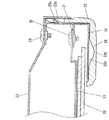
図5は図4に示すプラズマディスプレイ装置の要部構造を示す断面図である。 FIG. 5 is a cross-sectional view showing the main structure of the plasma display device shown in FIG.
図5に示すように、前記飾りパネル22の前面には、前記フレーム25上に配置される部分に連続的に肉厚を変化させた偏肉部22bを有しており、この偏肉部22bを形成した部分は、フレーム25との間に空間26が形成されている。また、前記フレーム25は、飾りパネル22の偏肉部22bと対応する部分に鏡面仕上げの表面25bを形成しており、飾りパネル22の偏肉部22bに入射した光は、フレーム25の表面25bで反射する際に、偏肉部22bの肉厚の変化に応じて、反射する光量も変化し、視覚的に立体的でかつグラデーション効果のあるデザインが得られることになる。 As shown in FIG. 5, on the front surface of the
また、前記表示パネル20は、保持板21の前面に、熱伝導性と弾性を有するシート27を介して接着することにより保持されている。さらに、金属製のフレーム25には、保持板21がビス28により電気的かつ機械的に接続され、また金属製のバックカバー23がビス29により電気的かつ機械的に接続されている。 The
また、飾りパネル22の側面には、金属製のフレーム25の側面に設けた切り起し片25cが嵌り合う孔22cが設けられており、フレーム25上に飾りパネル22を被せることにより、フレーム25の切り起し片25cが飾りパネル22の孔22cに嵌り合い、これにより、飾りパネル22がフレーム25に密着するように被せられることとなる。前記バックカバー23は、フレーム25に被せられた飾りパネル22の側面を覆うように、配置されている。 Further, the side surface of the
ここで、本発明による外装キャビネットの立体的なグラデーション効果のデザインについて説明する。 Here, the design of the three-dimensional gradation effect of the exterior cabinet according to the present invention will be described.
上述したように、飾りパネル22は、着色された光透過性の樹脂材料により構成するとともに、前記フレーム25上に配置される前面の一部に連続的に肉厚を変化させた偏肉部22bを形成した構成であり、そしてフレーム25の前面は、鏡面仕上げの表面25bとしているため、飾りパネル22の表面から入射した光は、偏肉部22bを透過して、フレーム25の表面25bに反射し、再び偏肉部22bを透過して戻ってくる。その際、偏肉部22bの肉厚の変化に応じて、戻ってくる光量も変化するため、立体的なグラデーション効果のあるデザインを実現できる。また、飾りパネル22に用いる樹脂材料の着色の濃さを調整することでもデザインを変化させることができ、例えば薄い色調にすると、フレーム25の金属感がより強調され、逆に濃い色調にするとダーク調の落ち着いたデザインを表現できる。 As described above, the
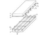
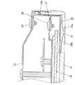
図6は本発明の他の実施の形態によるプラズマディスプレイ装置を示す分解斜視図、図7はその要部構造を示す断面図である。 FIG. 6 is an exploded perspective view showing a plasma display device according to another embodiment of the present invention, and FIG.
この図6、図7に示す例においては、前記表示パネル20の表示領域20aに対応するように透明な表示窓30aを有する平板形状のフロントパネル30と、前記バックカバー23とで外装キャビネットを構成したものである。フロントパネル30は開口部を持たず、段差のない平面を有する形状で、フレーム25の全体を覆う形状になっている。 In the example shown in FIGS. 6 and 7, an exterior cabinet is configured by the flat
そして、表示パネル20の非表示領域を覆う部分、すなわちフレーム25の前面に対応するフロントパネル30の周縁部の前面には、光の透過性を有し、かつ着色された樹脂からなる飾りパネル31が埋め込まれるように配置されている。さらに、飾りパネル31の前面には、前記フレーム25上に配置される部分に連続的に肉厚を変化させた偏肉部31aを有している。なお、前記フレーム25は、飾りパネル31の偏肉部31aと対応する部分に、鏡面仕上げの表面25bを形成しており、飾りパネル31の偏肉部31aに入射した光は、フレーム25の表面25bで反射する際に、偏肉部31aの肉厚の変化に応じて、反射する光量も変化し、視覚的に立体的でかつグラデーション効果のあるデザインが得られることになる。 A
以上説明したように本発明においては、表示パネル20およびこの表示パネル20に画像を表示するための駆動回路を搭載した回路基板を備えた表示モジュールと、前記表示パネル20の周縁部に配置される金属製のフレーム25と、前記表示モジュールを収容する外装キャビネットとを有し、前記外装キャビネットは、前記表示パネル20の前面側に前記フレーム25を覆うように配置される飾りパネル22、31と、前記表示モジュールの背面側を覆うバックカバー23とを備え、かつ前記飾りパネル22、31は、着色された光透過性の樹脂材料により構成するとともに、前記フレーム25上に配置される部分に連続的に肉厚を変化させた偏肉部22b、31aを形成したもので、飾りパネル22、31の表面から入射した光は、偏肉部22b、31aを透過して、フレーム25の表面25bに反射し、再び偏肉部22b、31aを透過して戻ってくる。その際、偏肉部22b、31aの肉厚の変化に応じて、戻ってくる光量も変化するため、立体的なグラデーション効果のあるデザインを実現できる。また、飾りパネル22、31に用いる樹脂材料の着色の濃さを調整することでもデザインを変化させることができ、例えば薄い色調にすると、フレーム25の金属感がより強調され、逆に濃い色調にするとダーク調の落ち着いたデザインを表現できる。 As described above, in the present invention, a display module including a
なお、上記実施の形態においては、フレーム25をアルミニウムやステンレスにより形成し、前面を鏡面仕上げとしたが、鏡面性のあるインキの塗装や印刷した鋼板、あるいは鏡面加工したシートをラミネートした鋼板を用いることも可能である。 In the above embodiment, the
以上のように本発明は、簡単な構成でディスプレイ装置のデザイン性を高める上で有用な発明である。 As described above, the present invention is useful for improving the design of a display device with a simple configuration.
20 表示パネル
21 保持板
22、31 飾りパネル
22b、31a 偏肉部
23 バックカバー
24 電磁遮蔽フィルタ
25 フレーム
30 フロントパネル20
Claims (6)
Translated fromJapanesePriority Applications (2)
| Application Number | Priority Date | Filing Date | Title |
|---|---|---|---|
| JP2011121351AJP2012247725A (en) | 2011-05-31 | 2011-05-31 | Display unit |
| US13/398,297US20120307463A1 (en) | 2011-05-31 | 2012-02-16 | Display device |
Applications Claiming Priority (1)
| Application Number | Priority Date | Filing Date | Title |
|---|---|---|---|
| JP2011121351AJP2012247725A (en) | 2011-05-31 | 2011-05-31 | Display unit |
Publications (1)
| Publication Number | Publication Date |
|---|---|
| JP2012247725Atrue JP2012247725A (en) | 2012-12-13 |
Family
ID=47261545
Family Applications (1)
| Application Number | Title | Priority Date | Filing Date |
|---|---|---|---|
| JP2011121351AWithdrawnJP2012247725A (en) | 2011-05-31 | 2011-05-31 | Display unit |
Country Status (2)
| Country | Link |
|---|---|
| US (1) | US20120307463A1 (en) |
| JP (1) | JP2012247725A (en) |
Families Citing this family (1)
| Publication number | Priority date | Publication date | Assignee | Title |
|---|---|---|---|---|
| US9468112B2 (en)* | 2013-08-09 | 2016-10-11 | Shenzhen China Star Optoelectronics Technology Co., Ltd. | Display device with narrow frame |
Family Cites Families (4)
| Publication number | Priority date | Publication date | Assignee | Title |
|---|---|---|---|---|
| US7108414B2 (en)* | 1995-06-27 | 2006-09-19 | Solid State Opto Limited | Light emitting panel assemblies |
| US6150007A (en)* | 1997-08-08 | 2000-11-21 | Meiwa Gravure Co., Ltd. | Fused decorative sheet |
| JP4319882B2 (en)* | 2003-09-29 | 2009-08-26 | 大日本印刷株式会社 | Decorative sheet, decorative molded product, and injection molding simultaneous decoration method |
| JP2005331556A (en)* | 2004-05-18 | 2005-12-02 | Matsushita Electric Ind Co Ltd | Flat panel display |
- 2011
- 2011-05-31JPJP2011121351Apatent/JP2012247725A/ennot_activeWithdrawn
- 2012
- 2012-02-16USUS13/398,297patent/US20120307463A1/ennot_activeAbandoned
Also Published As
| Publication number | Publication date |
|---|---|
| US20120307463A1 (en) | 2012-12-06 |
Similar Documents
| Publication | Publication Date | Title |
|---|---|---|
| KR101318034B1 (en) | Optical unit, back light assembly having the same, and display device having the back light assembly | |
| JP2009181118A (en) | Film filter and flat panel display having the same | |
| JP4660977B2 (en) | Plasma display device | |
| JP2004039578A (en) | Plasma display panel | |
| JP2007073508A (en) | Micro discharge type plasma display device | |
| JP2012247725A (en) | Display unit | |
| JP2012247726A (en) | Display device | |
| JP2013019980A (en) | Display device | |
| EP1391907A4 (en) | PLASMA SCREEN | |
| JP5408152B2 (en) | Flat panel display | |
| EP1526561A3 (en) | A plasma display | |
| ATE426244T1 (en) | PLASMA DISPLAY PANEL | |
| JP2013019981A (en) | Display device | |
| JP2012230286A (en) | Plasma display device | |
| US8174192B2 (en) | Plasma display panel | |
| JP2004226795A (en) | 3D image display device | |
| EP1942517A2 (en) | Plasma Display Device | |
| JP2004072149A (en) | Flat panel display | |
| EP3667406A1 (en) | Display device | |
| JP5375854B2 (en) | Electronics | |
| JP3744470B2 (en) | Plasma display device | |
| WO2012137757A1 (en) | Illumination device, display device, and television receiver device | |
| JP3861766B2 (en) | Flat panel display | |
| TW425535B (en) | Plasma display panel using light shading layer to control the color temperature | |
| KR20070111834A (en) | Front filter of plasma display panel |
Legal Events
| Date | Code | Title | Description |
|---|---|---|---|
| A300 | Application deemed to be withdrawn because no request for examination was validly filed | Free format text:JAPANESE INTERMEDIATE CODE: A300 Effective date:20140805 |