Movatterモバイル変換


[0]ホーム

URL:


JP2012245769A - Tape cassette - Google Patents

Tape cassette
Download PDF

Info

Publication number
JP2012245769A
JP2012245769AJP2011121751AJP2011121751AJP2012245769AJP 2012245769 AJP2012245769 AJP 2012245769AJP 2011121751 AJP2011121751 AJP 2011121751AJP 2011121751 AJP2011121751 AJP 2011121751AJP 2012245769 AJP2012245769 AJP 2012245769A
Authority
JP
Japan
Prior art keywords
tape
thermal
layer
color
heat
Prior art date
Legal status (The legal status is an assumption and is not a legal conclusion. Google has not performed a legal analysis and makes no representation as to the accuracy of the status listed.)
Withdrawn
Application number
JP2011121751A
Other languages
Japanese (ja)
Inventor
Susumu Murata
進 村田
Tsutomu Kato
努 加藤
Ryosuke Ishikawa
亮輔 石川
Terushiro Yamaguchi
晃志郎 山口
Current Assignee (The listed assignees may be inaccurate. Google has not performed a legal analysis and makes no representation or warranty as to the accuracy of the list.)
Brother Industries Ltd
Original Assignee
Brother Industries Ltd
Priority date (The priority date is an assumption and is not a legal conclusion. Google has not performed a legal analysis and makes no representation as to the accuracy of the date listed.)
Filing date
Publication date
Application filed by Brother Industries LtdfiledCriticalBrother Industries Ltd
Priority to JP2011121751ApriorityCriticalpatent/JP2012245769A/en
Publication of JP2012245769ApublicationCriticalpatent/JP2012245769A/en
Withdrawnlegal-statusCriticalCurrent

Links

Images

Landscapes

Abstract

Translated fromJapanese

【課題】複数のサーマルヘッドを用いずに複数の色を印刷でき、且つメーカーが効率よく容易にバリエーションを増やすことが可能なテープカセットを提供する。
【解決手段】テープカセット1は、サーマルヘッド64を備えたテープ印刷装置に装着できる。テープカセット1は、筐体と、第一感熱テープ22と、第二感熱テープ32と、貼り合わせ部43とを備える。第一感熱テープ22は、温度が所定の発色温度範囲となることで発色する黒色発色層を有する長尺状のテープである。第二感熱テープ32は、黒色発色層とは異なる温度範囲で発色する発色層を備える長尺状のテープである。貼り合わせ部43は、搬送経路のうち印刷位置53よりも上流側で、第一感熱テープ22と第二感熱テープ32とを貼り合わせる。
【選択図】図2
To provide a tape cassette capable of printing a plurality of colors without using a plurality of thermal heads and allowing a manufacturer to increase variations efficiently and easily.
A tape cassette 1 can be mounted on a tape printer provided with a thermal head 64. The tape cassette 1 includes a housing, a first thermal tape 22, a second thermal tape 32, and a bonding portion 43. The first heat-sensitive tape 22 is a long tape having a black coloring layer that develops color when the temperature falls within a predetermined coloring temperature range. The second heat-sensitive tape 32 is a long tape having a coloring layer that develops color in a temperature range different from that of the black coloring layer. The bonding unit 43 bonds the first thermal tape 22 and the second thermal tape 32 on the upstream side of the printing position 53 in the transport path.
[Selection] Figure 2

Description

Translated fromJapanese

本発明は、複数の色で印刷することが可能な長尺状のテープを収納するテープカセットに関する。  The present invention relates to a tape cassette that stores a long tape that can be printed in a plurality of colors.

従来、複数の色で印刷されたラベルテープを作成するための技術が知られている。例えば、特許文献1が開示しているテープ印字装置は2つのサーマルヘッドを備える。テープ印字装置が装着するテープカセットは、透明テープ、印字リボン、および感熱両面テープを収納している。テープ印字装置の第一サーマルヘッドは、印字リボンによって透明テープに対する印字を行う。第二サーマルヘッドは、感熱両面テープに熱を加えて印字を行う。印字リボンから透明テープに転写される色と、感熱両面テープで発色される色とは異なる。テープ印字装置は、透明テープおよび感熱両面テープの各々に対する印字が完了した後に、2つのテープを貼り合わせて外部に排出する。  Conventionally, a technique for producing a label tape printed in a plurality of colors is known. For example, the tape printer disclosed inPatent Document 1 includes two thermal heads. The tape cassette to which the tape printer is mounted contains a transparent tape, a print ribbon, and a heat-sensitive double-sided tape. The first thermal head of the tape printer performs printing on the transparent tape with a print ribbon. The second thermal head performs printing by applying heat to the heat-sensitive double-sided tape. The color transferred from the printing ribbon to the transparent tape is different from the color developed by the heat-sensitive double-sided tape. The tape printer attaches the two tapes and discharges them to the outside after printing on each of the transparent tape and the heat-sensitive double-sided tape is completed.

特開平6−1006号公報Japanese Patent Laid-Open No. 6-1006

特許文献1に記載の技術では2つのサーマルヘッドが必要となるため、テープ印刷装置の構成を簡素化することが困難である。一方で、1つのテープを収納したテープカセットを用いる場合、テープカセットのバリエーションを複数用意するためには、メーカーは予めバリエーションの数だけテープを製造してテープカセットに収納する必要があり、効率が悪かった。  Since the technique described inPatent Document 1 requires two thermal heads, it is difficult to simplify the configuration of the tape printer. On the other hand, when using a tape cassette containing a single tape, in order to prepare a plurality of variations of the tape cassette, it is necessary for the manufacturer to manufacture the tape in the number of variations in advance and store it in the tape cassette. It was bad.

本発明は、複数のサーマルヘッドを用いずに複数の色を印刷でき、且つメーカーが効率よく容易にバリエーションを増やすことが可能なテープカセットを提供することを目的とする。  It is an object of the present invention to provide a tape cassette that can print a plurality of colors without using a plurality of thermal heads and that allows a manufacturer to efficiently and easily increase variations.

本発明に係るテープカセットは、サーマルヘッドを備えたテープ印刷装置に装着可能なテープカセットであって、筐体と、前記筐体に収納され、温度が所定の発色温度範囲となることで発色する第一発色層を有する透明な長尺状のテープである第一感熱テープと、前記第一発色層の発色温度範囲とは異なる発色温度範囲で発色する第二発色層を有する長尺状のテープであり、前記第一感熱テープに貼り合わされていない状態で前記筐体に収納される第二感熱テープと、前記筐体内部における前記第一感熱テープおよび前記第二感熱テープの搬送経路のうち、前記サーマルヘッドによる印刷が行われる位置よりも上流側で、搬送される前記第一感熱テープと前記第二感熱テープとを貼り合わせる貼り合わせ部とを備える。  The tape cassette according to the present invention is a tape cassette that can be mounted on a tape printer equipped with a thermal head. The tape cassette is housed in the housing, and is colored when the temperature falls within a predetermined color development temperature range. A first heat-sensitive tape, which is a transparent long tape having a first color-developing layer, and a long tape having a second color-developing layer that develops a color in a temperature range different from the color temperature range of the first color-developing layer And the second thermal tape housed in the housing in a state where the first thermal tape is not bonded to the first thermal tape, and the first thermal tape and the second thermal tape inside the housing are transported, A bonding section for bonding the first heat-sensitive tape and the second heat-sensitive tape to be conveyed is provided upstream of a position where printing by the thermal head is performed.

本発明に係るテープカセットによると、テープ印刷装置は、1つのサーマルヘッドの発熱温度を調整することで、複数の色で印刷されたラベルテープを作成できる。複数のサーマルヘッドを備える必要が無い。さらに、メーカーは、第一感熱テープと第二感熱テープとを別々に作成し、適宜組み合わせて筐体に収納することで、テープカセットのバリエーションを効率よく増やすことができる。  According to the tape cassette of the present invention, the tape printer can produce a label tape printed in a plurality of colors by adjusting the heat generation temperature of one thermal head. There is no need to provide a plurality of thermal heads. Furthermore, the manufacturer can efficiently increase the variations of the tape cassette by separately preparing the first thermal tape and the second thermal tape and appropriately storing them in the housing.

前記貼り合わせ部は、回転軸を平行にした状態で対向配置される一対の貼り合わせローラを備えてもよい。前記一対の貼り合わせローラは、各々の外周面の間で前記第一感熱テープと前記第二感熱テープとを挟んで回転することで、前記第一感熱テープと前記第二感熱テープとを貼り合わせてもよい。一対の貼り合わせローラが回転しながら2つの感熱テープを貼り合わせるため、貼り合わせる際にしわや気泡の発生をなくし、確実に密着できる。また、テープを傷つける可能性を低下させることができる。  The laminating unit may include a pair of laminating rollers arranged to face each other with the rotation axis parallel. The pair of laminating rollers are bonded to the first thermal tape and the second thermal tape by rotating the first thermal tape and the second thermal tape between the outer peripheral surfaces of the pair of laminating rollers. May be. Since the two heat-sensitive tapes are bonded together while the pair of bonding rollers rotate, generation of wrinkles and bubbles is eliminated when the bonding is performed, and the two can be reliably adhered. In addition, the possibility of damaging the tape can be reduced.

前記第一感熱テープが有する前記第一発色層は、黒色に発色する層である黒色発色層を含んでもよい。ユーザは、透明な第一感熱テープ側(表側)から印刷結果を視認する。従って、黒色を印刷した際に、黒色発色層よりも裏側の層(例えば、第二発色層)が黒色発色層と共に発色してしまった場合でも、黒色発色層よりも裏側の層の発色部分は表側の黒色によって覆われる。よって、テープ印刷装置は、輪郭がくっきりとした鮮明な黒色を印刷することができる。  The first color developing layer of the first heat sensitive tape may include a black color developing layer that is a black color developing layer. The user visually recognizes the print result from the transparent first thermal tape side (front side). Therefore, when black is printed, even if the layer on the back side of the black color developing layer (for example, the second color developing layer) is colored together with the black color forming layer, the color developing portion of the layer behind the black color developing layer is Covered with black on the front side. Therefore, the tape printer can print clear black with a clear outline.

前記貼り合わせ部によって貼り合わされたテープのうち前記第一感熱テープ側が、前記テープ印刷装置の前記サーマルヘッドに接触してもよい。前記第一発色層および前記第二発色層の各々の発色温度範囲は、前記サーマルヘッドに接触する面から遠い層ほど低くてもよい。この場合、サーマルヘッドの熱が第一感熱テープ側から与えられることで、テープにおける熱の拡散状態が僅かなうちに、サーマルヘッドの熱が第一感熱テープの第一発色層に与えられる。第一発色層は、第二発色層よりも高い温度で発色する。さらに、第一発色層は隠蔽性が高い黒色発色層を含む。よって、第一発色層を発色させるための熱が第二感熱テープの第二発色層に拡散し、第二発色層が意図せず発色してしまった場合でも、第二発色層の発色は黒色によって隠蔽される。従って、第一発色層を高い温度で発色させれば、第二発色層の発色による混色を抑えることができ、輪郭がくっきりとした鮮明な印刷を行うことができる。  The first thermal tape side of the tape bonded by the bonding unit may contact the thermal head of the tape printer. The color development temperature range of each of the first color development layer and the second color development layer may be lower as the layer is farther from the surface in contact with the thermal head. In this case, the heat of the thermal head is applied from the first thermal tape side, so that the heat of the thermal head is applied to the first coloring layer of the first thermal tape while the heat diffusion state in the tape is slight. The first coloring layer develops color at a higher temperature than the second coloring layer. Further, the first color developing layer includes a black color developing layer having high concealability. Therefore, even if the heat for developing the first coloring layer diffuses to the second coloring layer of the second heat-sensitive tape and the second coloring layer unintentionally colors, the coloring of the second coloring layer is black. Concealed by. Therefore, if the first color-developing layer is colored at a high temperature, color mixing due to the color development of the second color-developing layer can be suppressed, and clear printing with clear outlines can be performed.

前記第一発色層および前記第二発色層は、前記サーマルヘッドに接触する面から遠い層ほど、発色するために必要な受熱時間が長くてもよい。この場合、サーマルヘッドによって熱を与える時間を短くすることで、サーマルヘッドに近い層を単独で発色させることができる。従って、輪郭がくっきりとした鮮明な印刷を行うことができる。  The first color-developing layer and the second color-developing layer may have a longer heat receiving time required for color development as the layer is farther from the surface in contact with the thermal head. In this case, by shortening the time during which heat is applied by the thermal head, a layer close to the thermal head can be colored independently. Therefore, clear printing with clear outlines can be performed.

前記第一感熱テープのうち前記第二感熱テープに貼り合わされる面、および前記第二感熱テープのうち前記第一感熱テープに貼り合わされる面の少なくともいずれかに、前記第一感熱テープと前記第二感熱テープとを接着する粘着剤層をさらに備えてもよい。この場合、第一感熱テープと第二感熱テープを強固に接着させることができる。  At least one of the surface of the first heat sensitive tape that is bonded to the second heat sensitive tape and the surface of the second heat sensitive tape that is bonded to the first heat sensitive tape are the first heat sensitive tape and the first heat sensitive tape. You may further provide the adhesive layer which adhere | attaches a two heat sensitive tape. In this case, the first heat sensitive tape and the second heat sensitive tape can be firmly bonded.

前記搬送経路のうち前記サーマルヘッドによる印刷が行われる位置よりも下流側に、前記貼り合わせ部によって貼り合わされたテープを搬送するテープ送りローラをさらに備えてもよい。この場合、テープ送りローラは、テープ印刷装置のローラと協働することで確実にテープを送り出すことができる。  You may further provide the tape feed roller which conveys the tape bonded by the said bonding part in the downstream rather than the position where printing by the said thermal head is performed among the said conveyance paths. In this case, the tape feeding roller can reliably feed the tape by cooperating with the roller of the tape printer.

テープカセット1を左斜め前方から見た斜視図である。It is the perspective view which looked at thetape cassette 1 from the diagonally left front.テープ印刷装置のカセット装着部60に装着されたテープカセット1の平面図である。It is a top view of thetape cassette 1 with which thecassette mounting part 60 of the tape printing apparatus was mounted | worn.貼り合わせ済テープ51の拡大斜視図である。3 is an enlarged perspective view of abonded tape 51. FIG.貼り合わせ済テープ51の各発色層の発色特性を示すグラフである。4 is a graph showing the color development characteristics of each color development layer of abonded tape 51.サーマルヘッド64の駆動電圧の波形と貼り合わせ済テープ51に対する印刷結果とを比較した図である。6 is a diagram comparing the waveform of the driving voltage of thethermal head 64 with the printing result on thebonded tape 51. FIG.変形例に係る貼り合わせ済テープの各発色層の発色特性を示すグラフである。It is a graph which shows the color development characteristic of each color development layer of the pasted tape concerning a modification.

以下、本発明を具現化した一実施の形態であるテープカセット1について、図面を参照して説明する。参照する図面は、本発明が採用し得る技術的特徴を説明するために用いられるものである。図面に記載されているテープカセット1の構成等は、それのみに限定する趣旨ではなく、単なる説明例である。  Hereinafter, atape cassette 1 according to an embodiment of the present invention will be described with reference to the drawings. The drawings to be referred to are used for explaining technical features that can be adopted by the present invention. The configuration and the like of thetape cassette 1 described in the drawings are not intended to be limited to this, but are merely illustrative examples.

以下の説明では、図1の右下側および図2の下側をテープカセット1の前側とする。図1の左上側および図2の上側をテープカセット1の後側とする。図1および図2の右側をテープカセット1の右側とする。図1および図2の左側をテープカセット1の左側とする。図1および図2の紙面手前側をテープカセット1の上側とする。図1および図2の紙面奥側をテープカセット1の下側とする。図2に示すテープカセット1は、上ケース8(図1参照)が取り外された状態のものである。  In the following description, the lower right side of FIG. 1 and the lower side of FIG. The upper left side of FIG. 1 and the upper side of FIG. The right side of FIGS. 1 and 2 is the right side of thetape cassette 1. The left side of FIGS. 1 and 2 is the left side of thetape cassette 1. The front side of the drawing in FIGS. 1 and 2 is the upper side of thetape cassette 1. The back side in FIG. 1 and FIG. 2 is the lower side of thetape cassette 1. Thetape cassette 1 shown in FIG. 2 is in a state where the upper case 8 (see FIG. 1) is removed.

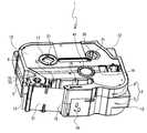
図1を参照して、テープカセット1の概略構成について説明する。テープカセット1は、全体として平面視で丸みを帯びた角を有する略直方体状(箱型)の筐体2を有する。筐体2は、下ケース3と上ケース8を備える。下ケース3は、板状の底壁4(図2参照)と、底壁4の外周縁から上方へ立設する側壁5とを備える。上ケース8は、上壁9と、上壁の外周縁から下方へ立設する側壁10とを備える。下ケース3と上ケース8とが嵌合して固定されることで筐体2が形成される。筐体2の内部には空間が形成される。筐体2は、内部に形成される空間にテープ等を収納する。  A schematic configuration of thetape cassette 1 will be described with reference to FIG. Thetape cassette 1 has a substantially rectangular parallelepiped (box-shaped) housing 2 having rounded corners in plan view as a whole. The housing 2 includes alower case 3 and anupper case 8. Thelower case 3 includes a plate-like bottom wall 4 (see FIG. 2) andside walls 5 erected upward from the outer peripheral edge of the bottom wall 4. Theupper case 8 includes an upper wall 9 and aside wall 10 erected downward from the outer peripheral edge of the upper wall. The case 2 is formed by fitting thelower case 3 and theupper case 8 together and fixing them. A space is formed inside the housing 2. The housing 2 stores a tape or the like in a space formed inside.

筐体2は、平面視で直角をなすように外側方向に突出する角部12を、4つの角のうちの3箇所に有する。筐体2の左前方の角にはテープ排出口13が設けられているため、左前方の角には角部12は設けられていない。角部12は、テープカセット1がテープ印刷装置(図示外)のカセット装着部60に装着された場合に、カセット装着部60の所定箇所に当接して支持される。  The housing | casing 2 has the corner |angular part 12 which protrudes in an outward direction so that a right angle may be made in planar view in three places of four corners. Since thetape discharge port 13 is provided at the left front corner of the housing 2, thecorner portion 12 is not provided at the left front corner. Thecorner portion 12 is supported in contact with a predetermined portion of thecassette mounting portion 60 when thetape cassette 1 is mounted on thecassette mounting portion 60 of the tape printer (not shown).

テープカセット1の前側にはアーム部14が設けられている。アーム部14は、後述する貼り合わせ済テープ51を案内し、開口15から送出する。アーム部14の後方にはヘッド装着部16が設けられている。テープカセット1がテープ印刷装置のカセット装着部60に装着されると、テープ印刷装置のヒートシンク63がヘッド装着部16に挿入される(図2参照)。  Anarm portion 14 is provided on the front side of thetape cassette 1. Thearm portion 14 guides a bondedtape 51 to be described later and sends it out from theopening 15. Ahead mounting portion 16 is provided behind thearm portion 14. When thetape cassette 1 is mounted on thecassette mounting portion 60 of the tape printer, theheat sink 63 of the tape printer is inserted into the head mounting portion 16 (see FIG. 2).

上ケース8の上壁9には3つの支持穴17〜19が設けられている。支持穴17は、上壁9の中心よりもやや左方に位置する。支持穴18は、上壁9の中心よりもやや右斜め後方に位置する。支持穴19は、上壁9の中心よりもやや右斜め前方に位置する。下ケース3には、上ケース8の3つの支持穴17〜19の各々の鉛直下方に支持穴(図示外)が設けられている。支持穴17は、対向する下ケース3の支持穴と共に第一テープスプール21を回転可能に支持する。同様に、支持穴18は第二テープスプール31を、支持穴19は中空ローラ41を、それぞれ回転可能に支持する。  Three support holes 17 to 19 are provided in the upper wall 9 of theupper case 8. Thesupport hole 17 is located slightly to the left of the center of the upper wall 9. Thesupport hole 18 is located slightly diagonally right behind the center of the upper wall 9. Thesupport hole 19 is located slightly diagonally forward to the right from the center of the upper wall 9. Thelower case 3 is provided with support holes (not shown) vertically below each of the threesupport holes 17 to 19 of theupper case 8. Thesupport hole 17 rotatably supports thefirst tape spool 21 together with the support hole of thelower case 3 that faces thesupport hole 17. Similarly, thesupport hole 18 rotatably supports thesecond tape spool 31, and thesupport hole 19 rotatably supports thehollow roller 41.

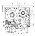
図2を参照して、テープカセット1の内部構造について説明する。第一テープスプール21には、長尺状の第一感熱テープ22が平面視反時計回りの向きに巻回されている。第二テープスプール31には、長尺状の第二感熱テープ32が平面視時計回りの向きに巻回されている。第一感熱テープ22および第二感熱テープ32の詳細については後述する。  The internal structure of thetape cassette 1 will be described with reference to FIG. A long firstthermal tape 22 is wound around thefirst tape spool 21 in a counterclockwise direction in plan view. A long second heat-sensitive tape 32 is wound around thesecond tape spool 31 in a clockwise direction in plan view. Details of the firstthermal tape 22 and the secondthermal tape 32 will be described later.

第一テープスプール21の右斜め前方には、テープ印刷装置のリボン巻き取り軸61が挿通される円筒状の中空ローラ41が設けられている。リボン巻き取り軸61は、インクリボンを備えたテープカセット(図示外)がカセット装着部60に装着された際に、リボン巻き取りスプール(図示外)の中心に挿入されて、リボン巻き取りスプールを回転させる。その結果、インクリボンはリボン巻き取りスプールに巻き取られる。本実施形態に係るテープカセット1はインクリボンおよびリボン巻取りスプールを備えていないが、リボン巻き取り軸61を備えたテープ印刷装置に装着することもできるように形成されている。中空ローラ41は、回転可能な状態でリボン巻き取り軸61の周囲を覆い、第一感熱テープ22に接触する。その結果、第一感熱テープ22は、リボン巻き取り軸61を迂回して円滑に、後述する貼り合わせ部43に搬送される。なお、第一感熱テープ22の破損を防止するためには、回転可能な中空ローラ41を用いて摩擦力を低下させることがより望ましい。しかし、中空ローラ41の代わりに、第一感熱テープ22との間の接触面が滑らかに湾曲したリブ等を用いてもよい。  A cylindricalhollow roller 41 through which the ribbon take-upshaft 61 of the tape printer is inserted is provided at an obliquely right front side of thefirst tape spool 21. The ribbon take-upshaft 61 is inserted into the center of the ribbon take-up spool (not shown) when a tape cassette (not shown) provided with an ink ribbon is attached to thecassette attaching portion 60. Rotate. As a result, the ink ribbon is taken up on the ribbon take-up spool. Thetape cassette 1 according to the present embodiment is not provided with an ink ribbon and a ribbon take-up spool, but is formed so that it can be attached to a tape printer provided with a ribbon take-upshaft 61. Thehollow roller 41 covers the periphery of the ribbon take-upshaft 61 in a rotatable state, and contacts the firstthermal tape 22. As a result, the first heat-sensitive tape 22 is smoothly transported to thebonding unit 43 described later, bypassing the ribbon take-upshaft 61. In order to prevent the firstthermal tape 22 from being damaged, it is more desirable to reduce the frictional force by using a rotatablehollow roller 41. However, instead of thehollow roller 41, a rib or the like whose contact surface with the firstthermal tape 22 is smoothly curved may be used.

テープカセット1の内部における右前の角部近傍には、貼り合わせ部43が設けられている。貼り合わせ部43は、第一貼り合わせローラ44と、第二貼り合わせローラ46と、リブ48と、板ばね50とを備える。第一貼り合わせローラ44は、上下方向に延びる回転軸45を中心として回転可能な状態で保持されている。第二貼り合わせローラ46は、第一貼り合わせローラ44の右方に対向配置されている。リブ48は、下ケース3の右側の側壁5から左方に延びている。リブ48には、左右方向を長径とする長穴49が上下方向に貫通している。長穴49には、上下方向に延びる第二貼り合わせローラ46の可動回転軸47が、回転可能且つ左右方向に揺動可能な状態で保持されている。板ばね50は、下ケース3の下側の側壁5から上方に延びており、第二貼り合わせローラ46の可動回転軸47を左方に付勢している。第一感熱テープ22および第二感熱テープ32は、第一貼り合わせローラ44と第二貼り合わせローラ46の間で貼り合わされる。  Abonding portion 43 is provided in the vicinity of the right front corner in thetape cassette 1. Thebonding unit 43 includes afirst bonding roller 44, asecond bonding roller 46, arib 48, and aleaf spring 50. The1st bonding roller 44 is hold | maintained in the state which can rotate centering on therotating shaft 45 extended to an up-down direction. Thesecond laminating roller 46 is disposed to face the right side of thefirst laminating roller 44. Therib 48 extends leftward from theright side wall 5 of thelower case 3. Anelongated hole 49 having a long diameter in the left-right direction passes through therib 48 in the up-down direction. A movablerotating shaft 47 of thesecond laminating roller 46 extending in the vertical direction is held in theelongated hole 49 so as to be rotatable and swingable in the horizontal direction. Theleaf spring 50 extends upward from thelower side wall 5 of thelower case 3 and urges the movablerotating shaft 47 of thesecond bonding roller 46 to the left. The firstthermal tape 22 and the secondthermal tape 32 are bonded between thefirst bonding roller 44 and thesecond bonding roller 46.

以上のように、貼り合わせ部43では、一対の貼り合わせローラ44,46が回転しながら第一感熱テープ22と第二感熱テープ32とを各々の外周面の間に挟んで貼り合わせる。従って、貼り合わせる際に感熱テープ22,32を傷つける可能性を低下させることができる。さらに、第二貼り合わせローラ46は第一貼り合わせローラ44へ向けて付勢されている。よって、貼り合わせ部43は、2つの感熱テープ22,32を押圧しながら確実に貼り合わせることができる。また、しわや気泡の発生をなくすこともできる。  As described above, in thelaminating portion 43, the pair oflaminating rollers 44 and 46 rotate and the first heat-sensitive tape 22 and the second heat-sensitive tape 32 are sandwiched and bonded between the outer peripheral surfaces. Therefore, it is possible to reduce the possibility of damaging the heat-sensitive tapes 22 and 32 at the time of bonding. Further, thesecond bonding roller 46 is urged toward thefirst bonding roller 44. Therefore, thebonding part 43 can be bonded reliably while pressing the twothermal tapes 22 and 32. In addition, generation of wrinkles and bubbles can be eliminated.

2つの感熱テープ22,32が貼り合わされた状態のテープを、以下では貼り合わせ済テープ51という。貼り合わせ済テープ51は、貼り合わせ部43からアーム部14に案内され、開口15から外部に搬送される。前述したように、アーム部14の後方にはヘッド装着部16が設けられている。ヘッド装着部16は、アーム部14の背面と、アーム部14の背面から連続して設けられた周壁面とによって囲まれた空間であり、テープカセット1を上下方向に貫通する。テープカセット1がカセット装着部60に装着されると、テープ印刷装置のヒートシンク63がヘッド装着部16に挿入される。ヒートシンク63の前方の壁面にはサーマルヘッド64が固定されている。貼り合わせ済テープ51の一方の面はサーマルヘッド64に対向する。サーマルヘッド64は、開口15から外部に搬送された貼り合わせ済テープ51に熱を加えることで、貼り合わせ済テープ51に対する印刷を実行し、ラベルテープを作成する。つまり、貼り合わせ済テープ51の搬送経路のうち、サーマルヘッド64に対向する位置(アーム部14の開口15の左方の位置)が、テープカセット1における印刷位置53となる。作成されたラベルテープは、テープ排出口13からテープカセット1の外部へ排出される。  Hereinafter, the tape in which the twothermal tapes 22 and 32 are bonded together is referred to as a bondedtape 51. The bondedtape 51 is guided from thebonding unit 43 to thearm unit 14 and conveyed to the outside through theopening 15. As described above, thehead mounting portion 16 is provided behind thearm portion 14. Thehead mounting portion 16 is a space surrounded by the back surface of thearm portion 14 and a peripheral wall surface continuously provided from the back surface of thearm portion 14, and penetrates thetape cassette 1 in the vertical direction. When thetape cassette 1 is mounted on thecassette mounting unit 60, theheat sink 63 of the tape printer is inserted into thehead mounting unit 16. Athermal head 64 is fixed to the wall surface in front of theheat sink 63. One surface of the bondedtape 51 faces thethermal head 64. Thethermal head 64 performs printing on the bondedtape 51 by applying heat to the bondedtape 51 conveyed to the outside through theopening 15 to create a label tape. That is, the position facing the thermal head 64 (the position on the left side of theopening 15 of the arm portion 14) in the transport path of the bondedtape 51 is theprinting position 53 in thetape cassette 1. The produced label tape is discharged from thetape discharge port 13 to the outside of thetape cassette 1.

貼り合わせ済テープ51の搬送方向における印刷位置53の下流側、つまり、テープカセット1の左下の角では、中空のテープ送りローラ52が回転可能に保持されている。テープ送りローラ52の内部には複数の爪部が形成されている。テープカセット1がカセット装着部60に装着されると、テープ印刷装置のテープ駆動軸66がテープ送りローラ52に挿入されて、テープ駆動軸66の外周に設けられたリブがテープ送りローラ52の爪部と噛み合う。テープ送りローラ52は、テープ駆動軸66によって回転されることで、後述する可動搬送ローラ71と共に貼り合わせ済テープ51を確実に搬送することができる。  On the downstream side of theprinting position 53 in the transport direction of the bondedtape 51, that is, at the lower left corner of thetape cassette 1, a hollowtape feed roller 52 is rotatably held. A plurality of claw portions are formed inside thetape feed roller 52. When thetape cassette 1 is mounted on thecassette mounting portion 60, thetape drive shaft 66 of the tape printer is inserted into thetape feed roller 52, and the ribs provided on the outer periphery of thetape drive shaft 66 are the claws of thetape feed roller 52. Engage with the part. Thetape feed roller 52 is rotated by thetape drive shaft 66 so that the bondedtape 51 can be reliably conveyed together with themovable conveyance roller 71 described later.

テープ印刷装置のカセット装着部60の前側には、アーム状のプラテンホルダ68が設けられている。プラテンホルダ68は、右端の軸支部69を中心に揺動可能に支持されている。プラテンホルダ68の先端側には、プラテンローラ70と可動搬送ローラ71とが回転可能に保持されている。プラテンローラ70はサーマルヘッド64に相対して接離可能に設けられており、可動搬送ローラ71はテープ送りローラ52に相対して接離可能に設けられている。テープ印刷装置では、カセット装着部60を覆うカバー(図示外)が閉鎖されると、プラテンホルダ68がヒートシンク63に近づく方向(時計回り方向)に移動する。その結果、プラテンローラ70は貼り合わせ済テープ51をサーマルヘッド64に押圧し、印刷可能な状態となる。可動搬送ローラ71は貼り合わせ済テープ51をテープ送りローラ52に押圧し、搬送可能な状態となる。  An arm-shapedplaten holder 68 is provided on the front side of thecassette mounting portion 60 of the tape printer. Theplaten holder 68 is supported so as to be able to swing around ashaft support portion 69 at the right end. Aplaten roller 70 and amovable conveyance roller 71 are rotatably held at the front end side of theplaten holder 68. Theplaten roller 70 is provided so as to be able to contact and separate relative to thethermal head 64, and themovable conveyance roller 71 is provided so as to be able to contact and separate relative to thetape feeding roller 52. In the tape printer, when the cover (not shown) covering thecassette mounting portion 60 is closed, theplaten holder 68 moves in the direction approaching the heat sink 63 (clockwise direction). As a result, theplaten roller 70 presses the bondedtape 51 against thethermal head 64 and becomes ready for printing. The movable conveyingroller 71 presses the bondedtape 51 against thetape feeding roller 52 and is in a state where it can be conveyed.

図3を参照して、第一感熱テープ22および第二感熱テープ32の構造について説明する。前述したように、第一感熱テープ22と第二感熱テープ32とが貼り合わされることで貼り合わせ済テープ51が形成され、貼り合わせ済テープ51に対して1つのサーマルヘッド64によって印刷が行われる。貼り合わせ済テープ51のうち第一感熱テープ22側の面(図3の上方の面)が、サーマルヘッド64に接触する面である。以下の説明では、図3の上方を表面側、図3の下方を裏面側として説明を行う。ユーザは、貼り合わせ済テープ51に印刷された結果を表面側(第一感熱テープ22側)から視認する。  With reference to FIG. 3, the structure of the 1stthermal tape 22 and the 2ndthermal tape 32 is demonstrated. As described above, the firstthermal tape 22 and the secondthermal tape 32 are bonded together to form the bondedtape 51, and printing is performed on the bondedtape 51 by onethermal head 64. . The surface on the firstthermal tape 22 side (the upper surface in FIG. 3) of the bondedtape 51 is a surface that contacts thethermal head 64. In the following description, the upper side of FIG. 3 is described as the front side, and the lower side of FIG. 3 is described as the back side. The user visually recognizes the result printed on the bondedtape 51 from the front side (firstthermal tape 22 side).

第一感熱テープ22は、透明な1または複数の層によって形成される。従って、ユーザは、表面側から貼り合わせ済テープ51を視認した場合に、第一感熱テープ22の裏面側に貼り合わされた第二感熱テープ32に対する印刷結果を視認することができる。第一感熱テープ22が備える層は、透明であれば有色であってもよいし、模様が施されていてもよい。本実施の形態に係る第一感熱テープ22は、受熱することで黒色に発色する透明な黒色発色層23を備える。黒色は、後述する第二感熱テープ32が発色する色よりも隠蔽性が高い色である。従って、黒色発色層23を発色させた場合、第二感熱テープ32が黒色発色層23と共に発色してしまった場合でも、第二感熱テープ32の発色部分は表面側の黒色によって覆われる。よって、輪郭がくっきりとした鮮明な黒色が印刷される。なお、第一感熱テープ22は、例えば黒色以外の紺色、茶色等、第二感熱テープ32が発色する色よりも隠蔽性が高い色に発色する層を備えれば、第二感熱テープ32の発色部分を覆うことができる。さらに、図示しないが、第一感熱テープ22は、黒色発色層23よりも表面側に、黒色発色層23を保護するオーバーコート層を備える。  The first heatsensitive tape 22 is formed of one or more transparent layers. Therefore, when the user visually recognizes the bondedtape 51 from the front surface side, the user can visually recognize the printing result for the secondthermal tape 32 bonded to the back surface side of the firstthermal tape 22. The layer provided in the firstthermal tape 22 may be colored as long as it is transparent, or may be patterned. The first heat-sensitive tape 22 according to the present embodiment includes a transparent blackcolor developing layer 23 that develops a black color when receiving heat. Black is a color with higher concealment than the color which the 2ndthermal tape 32 mentioned later colors. Therefore, when the blackcolor developing layer 23 is colored, even if the second heatsensitive tape 32 is colored together with the blackcolor developing layer 23, the colored portion of the second heatsensitive tape 32 is covered with black on the surface side. Therefore, a clear black with a clear outline is printed. If the firstthermal tape 22 includes a layer that develops a color that is more concealed than the color that the secondthermal tape 32 develops, such as a dark blue or brown color other than black, the color of the secondthermal tape 32 may be increased. Can cover the part. Further, although not shown, the firstthermal tape 22 includes an overcoat layer that protects the blackcolor developing layer 23 on the surface side of the blackcolor developing layer 23.

第二感熱テープ32は、表面側から順に、粘着剤層33、イエロー発色層34、マゼンタ発色層35、シアン発色層36、基材37、および剥離紙38を備える。粘着剤層33は、第一感熱テープ22と第二感熱テープ32とを強固に接着する。イエロー発色層34、マゼンタ発色層35、およびシアン発色層36は、受熱することでそれぞれイエロー、マゼンタ、およびシアンに発色する。イエロー、マゼンタ、およびシアンの各々の発色を調整することで、第二感熱テープ32では様々な色が表現される。イエロー発色層34、マゼンタ発色層35、およびシアン発色層36はいずれも透明な層であるため、ユーザは全ての層の発色を視認することができる。基材37は、第二感熱テープ32が備える他の層を支持する土台となる。基材37は透明でも不透明でもよい。さらに、基材37の裏面側には粘着剤が塗布されている。剥離紙38は、基材37の裏面に接離可能に設けられており、基材37の粘着剤を保護している。ユーザは、剥離紙38を取り除くことで、貼り合わせ済テープ51を粘着剤によって所望の場所に貼り付けることができる。なお、図示しないが、イエロー発色層34、マゼンタ発色層35、およびシアン発色層36の各々の間には中間層が積層されている。  The second heat-sensitive tape 32 includes anadhesive layer 33, ayellow coloring layer 34, amagenta coloring layer 35, acyan coloring layer 36, a base material 37, and a release paper 38 in this order from the surface side. The pressure-sensitive adhesive layer 33 firmly bonds the first heat-sensitive tape 22 and the second heat-sensitive tape 32. Theyellow coloring layer 34, themagenta coloring layer 35, and thecyan coloring layer 36 receive yellow, magenta, and cyan, respectively, by receiving heat. Various colors are expressed on the secondthermal tape 32 by adjusting the color development of yellow, magenta, and cyan. Since theyellow coloring layer 34, themagenta coloring layer 35, and thecyan coloring layer 36 are all transparent layers, the user can visually recognize the coloring of all the layers. The base material 37 serves as a base for supporting the other layers included in the secondthermal tape 32. The substrate 37 may be transparent or opaque. Further, an adhesive is applied to the back side of the substrate 37. The release paper 38 is provided on the back surface of the base material 37 so as to be able to contact and separate, and protects the adhesive of the base material 37. The user can attach the bondedtape 51 to a desired place with an adhesive by removing the release paper 38. Although not shown, an intermediate layer is laminated between each of theyellow coloring layer 34, themagenta coloring layer 35, and thecyan coloring layer 36.

図4を参照して、黒色発色層23、イエロー発色層34、マゼンタ発色層35、およびシアン発色層36の各々の発色温度範囲および必要受熱時間について説明する。発色温度範囲とは、発色層が発色するために必要な温度の範囲である。必要受熱時間とは、発色層が発色するために発色温度範囲を維持する必要がある時間である。  With reference to FIG. 4, the color development temperature range and the required heat receiving time of each of the blackcolor development layer 23, the yellowcolor development layer 34, the magentacolor development layer 35, and the cyancolor development layer 36 will be described. The color development temperature range is a temperature range necessary for the color development layer to develop color. The required heat receiving time is the time required to maintain the color development temperature range in order for the color development layer to develop color.

第一感熱テープ22が有する発色層の発色温度範囲と、第二感熱テープ32が有する発色層の発色温度範囲とは異なる。詳細には、第一感熱テープ22および第二感熱テープ32が有する複数の発色層の各々の発色温度範囲は、全て異なる。従って、テープ印刷装置は、貼り合わせ済テープ51に加える温度を調整することで、所定の発色層を発色させることができる。  The color development temperature range of the color development layer of the first heatsensitive tape 22 is different from the color development temperature range of the color development layer of the second heatsensitive tape 32. Specifically, the color developing temperature ranges of the plurality of color developing layers of the first heatsensitive tape 22 and the second heatsensitive tape 32 are all different. Therefore, the tape printer can color the predetermined color developing layer by adjusting the temperature applied to the bondedtape 51.

図4のグラフでは、「B」が黒色発色層23、「Y」がイエロー発色層34、「M」がマゼンタ発色層35、「C」がシアン発色層36を示す。図4に示すように、本実施の形態では、黒色発色層23、イエロー発色層34、マゼンタ発色層35、シアン発色層36の順に発色温度範囲が低くなるように設定されている。つまり、サーマルヘッド64に接触する表面から遠い層ほど、発色温度範囲は低くなる。具体的には、黒色発色層23の発色温度範囲は約190℃、イエロー発色層34の発色温度範囲は約160℃、マゼンタ発色層35の発色温度範囲は約130℃、シアン発色層36の発色温度範囲は約100℃である。裏面側の層の発色温度範囲が低いので、裏面側の層だけを発色させる場合には、サーマルヘッド64の温度を低くすればよい。一方、黒色を発色させる場合にはサーマルヘッドの温度を高くすればよい。ここで、黒色を発色させるための熱が仮に裏面側の層に伝わって、イエロー等の色が発色してしまっても、イエロー等の発色は隠蔽性が高い黒色に覆われて視認されない。よって、テープカセット1によると、テープ印刷装置は混色を抑制して目的の色を正確に印刷することができる。  In the graph of FIG. 4, “B” indicates theblack coloring layer 23, “Y” indicates theyellow coloring layer 34, “M” indicates themagenta coloring layer 35, and “C” indicates thecyan coloring layer 36. As shown in FIG. 4, in this embodiment, the blackcolor forming layer 23, the yellowcolor developing layer 34, the magentacolor developing layer 35, and the cyancolor developing layer 36 are set so that the color developing temperature range decreases in this order. That is, the color development temperature range becomes lower as the layer is farther from the surface in contact with thethermal head 64. Specifically, the color development temperature range of the blackcolor development layer 23 is about 190 ° C., the color development temperature range of the yellowcolor development layer 34 is about 160 ° C., the color development temperature range of the magentacolor development layer 35 is about 130 ° C., and the color development temperature of the cyancolor development layer 36. The temperature range is about 100 ° C. Since the color development temperature range of the back side layer is low, when only the back side layer is colored, the temperature of thethermal head 64 may be lowered. On the other hand, when black is to be developed, the temperature of the thermal head may be increased. Here, even if the heat for developing the black color is transmitted to the back side layer and the color of yellow or the like is developed, the color of yellow or the like is covered with black having high concealment and is not visually recognized. Therefore, according to thetape cassette 1, the tape printing apparatus can print the target color accurately while suppressing color mixing.

さらに、図4に示すように、サーマルヘッド64に接触する表面から遠い層ほど、必要受熱時間は長くなる。具体的には、黒色発色層23の必要受熱時間は約1ms、イエロー発色層34の必要受熱時間は約3ms、マゼンタ発色層35の必要受熱時間は約5ms、シアン発色層36の必要受熱時間は約8msである。従って、サーマルヘッド64によって熱を与える時間を調整することで、目的の色を正確に印刷することができる。詳細には、短い時間で高い温度を貼り合わせ済テープ51に与えることで、裏面側の層への熱の拡散状態が僅かなうちに表面側の層を発色させることができる。裏面側の層の温度は発色温度範囲に達し難く、且つ時間も必要受熱時間に達し難いため、裏面側の層を発色させずに表面側の層だけを発色させることができる。よって、テープ印刷装置は混色を抑制して目的の色を正確に印刷することができる。  Furthermore, as shown in FIG. 4, the required heat receiving time becomes longer as the layer is farther from the surface in contact with thethermal head 64. Specifically, the required heat receiving time of the blackcolor developing layer 23 is about 1 ms, the required heat receiving time of theyellow coloring layer 34 is about 3 ms, the required heat receiving time of themagenta coloring layer 35 is about 5 ms, and the required heat receiving time of thecyan coloring layer 36 is About 8 ms. Therefore, the target color can be accurately printed by adjusting the time during which heat is applied by thethermal head 64. Specifically, by applying a high temperature to the bondedtape 51 in a short time, the surface layer can be colored while the heat diffusion state to the back layer is slight. Since the temperature of the back side layer does not easily reach the color development temperature range, and the time does not easily reach the required heat receiving time, only the front side layer can be colored without coloring the back side layer. Thus, the tape printer can accurately print the target color while suppressing color mixing.

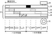
図5を参照して、貼り合わせ済テープ51を発色させるための制御方法について説明する。図5の上段は、サーマルヘッド64によって印刷が行われた貼り合わせ済テープ51を模式的に示す平面図である。貼り合わせ済テープ51は、プラテンローラ70によってサーマルヘッド64に押圧され、且つ図5の左方に搬送されながら、サーマルヘッド64の熱によって発色する。図5の下段は、サーマルヘッド64に印加する駆動電圧の波形を印刷箇所と比較して示す説明図である。なお、図5において点線で囲まれる領域は、サーマルヘッド64の駆動電圧を「OFF」から「ON」に変更すると発色する領域を示す。  A control method for coloring the bondedtape 51 will be described with reference to FIG. The upper part of FIG. 5 is a plan view schematically showing the bondedtape 51 printed by thethermal head 64. The bondedtape 51 is pressed by thethermal head 64 by theplaten roller 70 and is colored by the heat of thethermal head 64 while being conveyed to the left in FIG. The lower part of FIG. 5 is an explanatory diagram showing the waveform of the drive voltage applied to thethermal head 64 in comparison with the print location. In FIG. 5, a region surrounded by a dotted line indicates a region that develops color when the drive voltage of thethermal head 64 is changed from “OFF” to “ON”.

貼り合わせ済テープ51に対する印刷を実行する場合、テープ印刷装置は、サーマルヘッド64の駆動方法を、ブラック、イエロー、マゼンタ、シアンの各々に対して個別に設定する。本実施の形態では、テープ印刷装置は、ブラック、イエロー、マゼンタ、シアンの順に、サーマルヘッド64に印加する電力(サーマルヘッド64の発熱温度)を低くすればよい。また、テープ印刷装置は、ブラック、イエロー、マゼンタ、シアンの順に電圧の印加時間を長くすればよい。図5に示す例では、左側の一印字周期の駆動制御において、ブラックを発色させるための駆動電圧のみが「OFF」とされている。その結果、イエロー発色層34、マゼンタ発色層35、およびシアン発色層36が発色する。また、図5の右側の一印字周期の駆動制御では、ブラックを発色させるための駆動電圧のみが「ON」とされている。その結果、黒色発色層23のみが発色する。以上のように、サーマルヘッド64の駆動方法(電力および印加時間)を調整することで、テープ印刷装置は種々の色を貼り合わせ済テープ51に発色させることができる。  When performing printing on the bondedtape 51, the tape printer individually sets the driving method of thethermal head 64 for each of black, yellow, magenta, and cyan. In the present embodiment, the tape printer may reduce the power applied to the thermal head 64 (the heat generation temperature of the thermal head 64) in the order of black, yellow, magenta, and cyan. In the tape printer, the voltage application time may be increased in the order of black, yellow, magenta, and cyan. In the example shown in FIG. 5, only the drive voltage for coloring black is set to “OFF” in the drive control in the left one printing cycle. As a result, theyellow coloring layer 34, themagenta coloring layer 35, and thecyan coloring layer 36 are colored. Further, in the drive control of one printing cycle on the right side of FIG. 5, only the drive voltage for coloring black is set to “ON”. As a result, only the blackcolor developing layer 23 develops color. As described above, by adjusting the driving method (power and application time) of thethermal head 64, the tape printing apparatus can develop various colors on the bondedtape 51.

以上説明したように、本実施の形態に係るテープカセット1によると、テープ印刷装置は、1つのサーマルヘッド64の駆動方法を調整することで、複数の色で印刷されたラベルテープを作成できる。テープ印刷装置はサーマルヘッド64を複数備える必要がない。さらに、メーカーは、第一感熱テープ22と第二感熱テープ32とを別々に作成し、適宜組み合わせて筐体2に収納することで、テープカセットのバリエーションを効率良く増やすことができる。例えば、メーカーは、デザイン(無地、マット調、セピア調等)が異なるN種の第一感熱テープ22を作成する。同様に、基材37の色、発色の色目等が異なるM種の第二感熱テープ32を作成する。この場合、N種の第一感熱テープ22の1つと、M種の第二感熱テープ32の1つとを適宜選択して筐体2に収納することで、N×M種のバリエーションのテープカセット1を容易に作成することができる。N×M種の貼り合わせ済テープ51を予め作成しておく場合に比べて、在庫管理等も容易である。  As described above, according to thetape cassette 1 according to the present embodiment, the tape printing apparatus can create a label tape printed in a plurality of colors by adjusting the driving method of onethermal head 64. The tape printer does not need to include a plurality ofthermal heads 64. Furthermore, the manufacturer can efficiently increase the variation of the tape cassette by separately preparing the firstthermal tape 22 and the secondthermal tape 32 and appropriately storing them in the housing 2. For example, the manufacturer creates N types of firstthermal tapes 22 having different designs (solid, matte, sepia, etc.). Similarly, M types of secondthermal tapes 32 in which the color of the substrate 37, the color of the developed color, and the like are different are prepared. In this case, by appropriately selecting one of the N types of firstthermal tapes 22 and one of the M types of secondthermal tapes 32 and storing them in the housing 2, thetape cassette 1 of N × M types of variations is provided. Can be easily created. Compared with the case where N × M types of bondedtapes 51 are prepared in advance, inventory management and the like are easier.

第一感熱テープ22と第二感熱テープ32とを予め貼り合わせて1つのロールにし、筐体2に収納すると、テープの収納位置および収納量が制限されやすい。第一感熱テープ22と第二感熱テープ32とを別々にロール状にして筐体2に収納することで、より自由にテープを筐体2に収納することができる。具体的には、筐体2の内部には、中空ローラ41、アーム部14、ヘッド装着部16等の多数の部材が設けられている。しかし、2つの感熱テープ22,32を別々に収納することで、部材の隙間を有効活用して容易に感熱テープ22,32を収納することができる。  If the 1st heatsensitive tape 22 and the 2nd heatsensitive tape 32 are pasted together and made into one roll, and it stores in case 2, it will be easy to restrict the storage position and storage amount of a tape. By separately forming the firstthermal tape 22 and the secondthermal tape 32 in a roll shape and storing them in the casing 2, the tape can be stored in the casing 2 more freely. Specifically, a large number of members such as thehollow roller 41, thearm portion 14, and thehead mounting portion 16 are provided in the housing 2. However, by storing the twothermal tapes 22 and 32 separately, thethermal tapes 22 and 32 can be easily stored by effectively utilizing the gaps between the members.

テープカセット1は、一対の貼り合わせローラ(第一貼り合わせローラ44および第二貼り合わせローラ46)を回転させながら2つの感熱テープ22,32を貼り合わせる。従って、貼り合わせる際に感熱テープ22,32を傷つける可能性を低下させることができる。しわや気泡が生じる可能性も低下する。また、板ばね50が第二貼り合わせローラ46を第一貼り合わせローラ44へ付勢するため、2つの感熱テープ22,32を押圧しながら確実に貼り合わせることができる。  Thetape cassette 1 bonds the two heat-sensitive tapes 22 and 32 while rotating a pair of bonding rollers (first bonding roller 44 and second bonding roller 46). Therefore, it is possible to reduce the possibility of damaging the heat-sensitive tapes 22 and 32 at the time of bonding. The possibility of wrinkles and bubbles is also reduced. Further, since theleaf spring 50 biases thesecond laminating roller 46 to thefirst laminating roller 44, the twothermal tapes 22 and 32 can be securely bonded while being pressed.

第一感熱テープ22は、黒色に発色する層である黒色発色層23を含む。従って、貼り合わせ済テープ51に黒色が印刷された場合に、黒色発色層23よりも裏面側の層が黒色発色層23と共に意図せず発色してしまった場合でも、意図せず発色した層は黒色によって覆われる。よって、テープ印刷装置は、輪郭がくっきりとした鮮明な黒色を印刷することができる。  The first heat-sensitive tape 22 includes a blackcolor developing layer 23 that is a black color developing layer. Therefore, when black is printed on the bondedtape 51, even if the layer on the back side of the blackcolor forming layer 23 is unintentionally colored together with the blackcolor developing layer 23, the unintentionally colored layer is Covered by black color. Therefore, the tape printer can print clear black with a clear outline.

サーマルヘッド64の熱は、貼り合わせ済テープ51における熱の拡散状態が僅かなうちに、第一感熱テープ22の黒色発色層23に与えられる。黒色発色層23は、第二感熱テープ32の発色層34〜36よりも高い温度で発色する。よって、黒色発色層23を発色させるための熱が第二感熱テープ32に拡散し、第二感熱テープ32の発色層34〜36のいずれかが意図せず発色してしまった場合でも、第二感熱テープ32で生じた発色は黒色によって隠蔽される。従って、テープ印刷装置は、黒色発色層23を高い温度で発色させれば、第二感熱テープ32の発色層34〜36の発色による混色を抑えることができ、輪郭がくっきりとした鮮明な印刷を行うことができる。  The heat of thethermal head 64 is given to theblack coloring layer 23 of the firstthermal tape 22 while the heat diffusion state in the bondedtape 51 is slight. Theblack coloring layer 23 develops color at a temperature higher than the coloring layers 34 to 36 of the secondthermal tape 32. Therefore, even if the heat for causing theblack coloring layer 23 to develop color diffuses to the secondthermal tape 32 and any one of the coloring layers 34 to 36 of the secondthermal tape 32 unintentionally develops color, The color developed on the heat-sensitive tape 32 is hidden by black. Therefore, if the blackcolor developing layer 23 is colored at a high temperature, the tape printer can suppress the color mixture due to the color development of thecolor developing layers 34 to 36 of the secondthermal tape 32 and can perform clear printing with a clear outline. It can be carried out.

貼り合わせ済テープ51が有する複数の発色層の各々の必要受熱時間は、サーマルヘッド64に接触する面から遠い層ほど長い。従って、テープ印刷装置は、サーマルヘッド64によって熱を与える時間を短くすることで、サーマルヘッド64に近い層を単独で発色させることができる。よって、輪郭がくっきりとした鮮明な印刷を行うことができる。  The required heat receiving time of each of the plurality of coloring layers of the bondedtape 51 is longer as the layer is farther from the surface in contact with thethermal head 64. Therefore, the tape printing apparatus can develop a layer close to thethermal head 64 independently by shortening the time for applying heat by thethermal head 64. Therefore, clear printing with clear outlines can be performed.

第二感熱テープ32のうち第一感熱テープ22に貼り合わされる面には粘着剤層が設けられている。よって、テープカセット1は、第一感熱テープ22と第二感熱テープ32とを強固に接着させることができる。また、テープの搬送経路のうち、印刷位置53よりも下流側に、テープ送りローラ52が設けられている。従って、テープカセット1は、テープ印刷装置の可動搬送ローラ71と協働することで確実に貼り合わせ済テープ51を送り出すことができる。  An adhesive layer is provided on the surface of the second heat-sensitive tape 32 that is bonded to the first heat-sensitive tape 22. Therefore, thetape cassette 1 can adhere | attach the 1st heatsensitive tape 22 and the 2nd heatsensitive tape 32 firmly. Further, atape feed roller 52 is provided on the downstream side of theprinting position 53 in the tape transport path. Therefore, thetape cassette 1 can reliably feed the bondedtape 51 by cooperating with themovable conveyance roller 71 of the tape printer.

上記実施の形態において、黒色発色層23が本発明の「第一発色層」に相当する。イエロー発色層34、マゼンタ発色層35、およびシアン発色層36が「第二発色層」に相当する。第一貼り合わせローラ44および第二貼り合わせローラ46が「一対の貼り合わせローラ」に相当する。  In the above embodiment, theblack coloring layer 23 corresponds to the “first coloring layer” of the present invention. Theyellow coloring layer 34, themagenta coloring layer 35, and thecyan coloring layer 36 correspond to the “second coloring layer”. Thefirst bonding roller 44 and thesecond bonding roller 46 correspond to “a pair of bonding rollers”.

本発明は上記実施の形態に限定されることはなく、様々な変形が可能であることは言うまでもない。例えば、各発色層の発色温度範囲および必要受熱時間は変更できる。図6を参照して、テープカセット1の変形例に係る黒色発色層23、イエロー発色層34、マゼンタ発色層35、およびシアン発色層36の各々の発色温度範囲および必要受熱時間について説明する。図6に示す変形例では、各発色層の発色温度範囲は上記実施の形態と同じである。イエロー発色層34、マゼンタ発色層35、およびシアン発色層36の必要受熱時間も、上記実施の形態と同じである。しかし、黒色発色層23の必要受熱時間は、上記実施の形態とは異なり、イエロー発色層34、マゼンタ発色層35、およびシアン発色層36の必要受熱時間の全てを含んでいる。図6に示す変形例のように、黒色発色層23の必要受熱時間の幅を広く設定しても本発明は実現できる。  It goes without saying that the present invention is not limited to the above-described embodiment, and various modifications are possible. For example, the color temperature range and the required heat receiving time of each color layer can be changed. With reference to FIG. 6, the color temperature range and the required heat receiving time of each of theblack color layer 23, theyellow color layer 34, themagenta color layer 35, and thecyan color layer 36 according to a modification of thetape cassette 1 will be described. In the modification shown in FIG. 6, the color temperature range of each color layer is the same as that in the above embodiment. The required heat receiving times of theyellow coloring layer 34, themagenta coloring layer 35, and thecyan coloring layer 36 are also the same as those in the above embodiment. However, the required heat receiving time of the blackcolor forming layer 23 includes all of the required heat receiving times of the yellowcolor forming layer 34, the magentacolor forming layer 35, and the cyancolor forming layer 36, unlike the above embodiment. As in the modification shown in FIG. 6, the present invention can be realized even if the required heat receiving time of the blackcolor forming layer 23 is set wide.

また、前述したように、各発色層の発色温度範囲は、サーマルヘッド64から遠い層ほど低く設定することが望ましい。しかし、各発色層の発色温度範囲が互いに異なれば、サーマルヘッド64の温度を調整することで種々の色を発色させることができるため、本発明は実現できる。また、各発色層の必要受熱時間は、サーマルヘッド64から遠い層ほど長く設定することが望ましい。しかし、各発色層の必要受熱時間を変更しても本発明は実現可能である。例えば、各発色層の必要受熱時間を均一に設定しても本発明は実現できる。  Further, as described above, it is desirable that the color development temperature range of each color development layer be set lower as the layer is farther from thethermal head 64. However, if the color development temperature ranges of the color development layers are different from each other, various colors can be developed by adjusting the temperature of thethermal head 64, and thus the present invention can be realized. Further, it is desirable that the required heat receiving time of each color forming layer is set longer as the layer is farther from thethermal head 64. However, the present invention can be realized even if the required heat receiving time of each color forming layer is changed. For example, the present invention can be realized even when the required heat receiving time of each color forming layer is set uniformly.

第一感熱テープ22が有する発色層(第一発色層)の色および数と、第二感熱テープ32が有する発色層(第二発色層)の色および数は、適宜変更が可能である。例えば、第一発色層を1つの層(例えば、青色発色層)とし、且つ第二発色層を1つの層(例えば、赤色発色層)としてもよい。また、上記実施の形態の第一発色層は黒色発色層23のみであるが、複数の発色層で第一発色層を構成してもよい。この場合、第一発色層は、隠蔽性の高い色(例えば、黒)に発色する発色層を含んでいることが望ましい。隠蔽性の高い色に発色する発色層を第一発色層が含むことで、第二発色層が意図せず発色した場合の混色を抑制することができる。さらに、隠蔽性の高い色に発色する発色層は、第一発色層のうち最も表面側(ユーザが視認する側)に位置することがより望ましい。この場合、隠蔽性の高い色に発色する発色層は、第二発色層に加え、第一発色層のうち裏面側に位置する層も隠蔽することができるため、さらに鮮明な印刷結果が得られる。  The color and number of the coloring layer (first coloring layer) included in the firstthermal tape 22 and the color and number of the coloring layer (second coloring layer) included in the secondthermal tape 32 can be appropriately changed. For example, the first coloring layer may be a single layer (for example, a blue coloring layer) and the second coloring layer may be a single layer (for example, a red coloring layer). In addition, the first color forming layer of the above embodiment is only the blackcolor forming layer 23, but the first color forming layer may be constituted by a plurality of color forming layers. In this case, it is desirable that the first coloring layer includes a coloring layer that develops a highly concealing color (for example, black). When the first color developing layer includes a color developing layer that develops a color with high concealability, color mixing when the second color developing layer unintentionally develops color can be suppressed. Furthermore, it is more desirable that the color developing layer that develops a color with high concealment is located on the most surface side (side that is visually recognized by the user) of the first color developing layer. In this case, the color-developing layer that develops a highly concealable color can also conceal the layer located on the back side of the first color-developing layer in addition to the second color-developing layer, so that a clearer printing result can be obtained. .

上記実施の形態では、第二感熱テープ32のうち第一感熱テープ22に貼り合わされる面に粘着剤層33が設けられている。しかし、粘着剤層33は、第一感熱テープ22の裏面側に設けられてもよいし、第一感熱テープ22および第二感熱テープ32の両方に設けられていてもよい。また、第一感熱テープ22および第二感熱テープ32の少なくともいずれかが非常に薄く形成されていれば、2つの感熱テープ22,32は静電気のみによって強固に貼り合わされる場合がある。このような場合、粘着剤層33を設ける必要は無い。また、第二感熱テープ32の基材37および剥離紙38も省略することができる。  In the said embodiment, theadhesive layer 33 is provided in the surface bonded together to the 1stthermal tape 22 among the 2ndthermal tapes 32. FIG. However, the pressure-sensitive adhesive layer 33 may be provided on the back side of the firstthermal tape 22 or may be provided on both the firstthermal tape 22 and the secondthermal tape 32. Further, if at least one of the firstthermal tape 22 and the secondthermal tape 32 is formed very thin, the twothermal tapes 22 and 32 may be firmly bonded only by static electricity. In such a case, it is not necessary to provide theadhesive layer 33. Further, the base material 37 and the release paper 38 of the secondthermal tape 32 can also be omitted.

上記実施の形態では、第一感熱テープ22および第二感熱テープ32はいずれもロール状に巻回されて筐体2に収納される。しかし、2つの感熱テープ22,32の収納態様は変更できる。例えば、2つの感熱テープ22,32の少なくともいずれかを折り畳んだ状態で収納することも可能である。この場合でも、2つの感熱テープ22,32を別々に収納して筐体2内で貼り合わせることで、前述した種々の効果が得られる。また、上記実施の形態において、2つの感熱テープ22,32が巻回される方向(時計回り方向または反時計回り方向)を適宜変更できることは言うまでもない。  In the above embodiment, both the firstthermal tape 22 and the secondthermal tape 32 are wound in a roll shape and stored in the housing 2. However, the storage mode of the twothermal tapes 22 and 32 can be changed. For example, at least one of the twothermal tapes 22 and 32 can be stored in a folded state. Even in this case, the above-described various effects can be obtained by separately storing the twothermal tapes 22 and 32 and bonding them together in the housing 2. In the above embodiment, it goes without saying that the direction in which the twothermal tapes 22 and 32 are wound (clockwise direction or counterclockwise direction) can be appropriately changed.

上記実施の形態における貼り合わせ部43は、板ばね50によって第二貼り合わせローラ46を第一貼り合わせローラ44に付勢することで、強固に2つの感熱テープ22,32を貼り合わせることができる。しかし、ローラを付勢せずに2つの感熱テープ22,32を貼り合わせることも可能である。また、板ばね50の代わりにコイルバネ等の他の付勢手段を用いてもよい。第一貼り合わせローラ44および第二貼り合わせローラ46の少なくとも一方を、回転不可能なリブ等に替えてもよい。  Thebonding portion 43 in the above embodiment can firmly bond the twothermal tapes 22 and 32 by urging thesecond bonding roller 46 to thefirst bonding roller 44 by theleaf spring 50. . However, the twothermal tapes 22 and 32 can be bonded together without urging the rollers. Further, instead of theleaf spring 50, other urging means such as a coil spring may be used. At least one of thefirst bonding roller 44 and thesecond bonding roller 46 may be replaced with a non-rotatable rib or the like.

1 テープカセット
2 筐体
16 ヘッド装着部
22 第一感熱テープ
23 黒色発色層
32 第二感熱テープ
33 粘着剤層
34 イエロー発色層
35 マゼンタ発色層
36 シアン発色層
43 貼り合せ部
44 第一貼り合わせローラ
46 第二貼り合わせローラ
51 貼り合わせ済テープ
52 テープ送りローラ
53 印刷位置
60 カセット装着部
64 サーマルヘッド
DESCRIPTION OFSYMBOLS 1 Tape cassette 2 Housing | casing 16Head mounting part 22 1st heatsensitive tape 23 Blackcolor developing layer 32 2nd heatsensitive tape 33Adhesive layer 34 Yellowcolor developing layer 35 Magentacolor developing layer 36 Cyancolor developing layer 43Bonding part 441st bonding roller 46Second bonding roller 51Bonded tape 52Tape feed roller 53Printing position 60Cassette mounting portion 64 Thermal head

Claims (7)

Translated fromJapanese
サーマルヘッドを備えたテープ印刷装置に装着可能なテープカセットであって、
筐体と、
前記筐体に収納され、温度が所定の発色温度範囲となることで発色する第一発色層を有する透明な長尺状のテープである第一感熱テープと、
前記第一発色層の発色温度範囲とは異なる発色温度範囲で発色する第二発色層を有する長尺状のテープであり、前記第一感熱テープに貼り合わされていない状態で前記筐体に収納される第二感熱テープと、
前記筐体内部における前記第一感熱テープおよび前記第二感熱テープの搬送経路のうち、前記サーマルヘッドによる印刷が行われる位置よりも上流側で、搬送される前記第一感熱テープと前記第二感熱テープとを貼り合わせる貼り合わせ部と
を備えたことを特徴とするテープカセット。
A tape cassette that can be mounted on a tape printer equipped with a thermal head,
A housing,
A first heat-sensitive tape that is housed in the housing and is a transparent long tape having a first color-developing layer that develops color when the temperature falls within a predetermined color development temperature range;
A long tape having a second color developing layer that develops a color in a temperature range different from the color developing temperature range of the first color developing layer, and is housed in the housing without being bonded to the first heat sensitive tape. Second thermal tape
The first thermal tape and the second thermal tape that are transported on the upstream side of the position where printing by the thermal head is performed in the transport path of the first thermal tape and the second thermal tape inside the housing. A tape cassette comprising a laminating portion for laminating a tape.
前記貼り合わせ部は、回転軸を平行にした状態で対向配置される一対の貼り合わせローラを備え、
前記一対の貼り合わせローラは、各々の外周面の間で前記第一感熱テープと前記第二感熱テープとを挟んで回転することで、前記第一感熱テープと前記第二感熱テープとを貼り合わせることを特徴とする請求項1に記載のテープカセット。
The laminating portion includes a pair of laminating rollers arranged to face each other in a state where the rotation axis is parallel.
The pair of laminating rollers are bonded to the first thermal tape and the second thermal tape by rotating with the first thermal tape and the second thermal tape between the outer peripheral surfaces. The tape cassette according to claim 1.
前記第一感熱テープが有する前記第一発色層は、黒色に発色する層である黒色発色層を含むことを特徴とする請求項1または2に記載のテープカセット。  3. The tape cassette according to claim 1, wherein the first color developing layer of the first heat sensitive tape includes a black color developing layer which is a black color developing layer. 4. 前記貼り合わせ部によって貼り合わされたテープのうち前記第一感熱テープ側が、前記テープ印刷装置の前記サーマルヘッドに接触し、
前記第一発色層および前記第二発色層の各々の発色温度範囲は、前記サーマルヘッドに接触する面から遠い層ほど低いことを特徴とする請求項3に記載のテープカセット。
The first thermal tape side of the tape bonded by the bonding unit is in contact with the thermal head of the tape printer,
4. The tape cassette according to claim 3, wherein the color development temperature range of each of the first color development layer and the second color development layer is lower in a layer farther from the surface in contact with the thermal head.
前記第一発色層および前記第二発色層は、前記サーマルヘッドに接触する面から遠い層ほど、発色するために必要な受熱時間が長いことを特徴とする請求項1から4のいずれかに記載のテープカセット。  5. The heat receiving time required for color development of the first color development layer and the second color development layer is longer in a layer farther from the surface in contact with the thermal head. 6. Tape cassette. 前記第一感熱テープのうち前記第二感熱テープに貼り合わされる面、および前記第二感熱テープのうち前記第一感熱テープに貼り合わされる面の少なくともいずれかに、前記第一感熱テープと前記第二感熱テープとを接着する粘着剤層をさらに備えたことを特徴とする請求項1から5のいずれかに記載のテープカセット。  At least one of the surface of the first heat sensitive tape that is bonded to the second heat sensitive tape and the surface of the second heat sensitive tape that is bonded to the first heat sensitive tape are the first heat sensitive tape and the first heat sensitive tape. The tape cassette according to any one of claims 1 to 5, further comprising a pressure-sensitive adhesive layer for bonding the two heat-sensitive tapes. 前記搬送経路のうち前記サーマルヘッドによる印刷が行われる位置よりも下流側に、前記貼り合わせ部によって貼り合わされたテープを搬送するテープ送りローラをさらに備えたことを特徴とする請求項1から6のいずれかに記載のテープカセット。  The tape feeding roller which conveys the tape bonded by the said bonding part in the downstream from the position where printing by the said thermal head is performed among the said conveyance paths, The further characterized by the above-mentioned. A tape cassette according to any one of the above.
JP2011121751A2011-05-312011-05-31Tape cassetteWithdrawnJP2012245769A (en)

Priority Applications (1)

Application NumberPriority DateFiling DateTitle
JP2011121751AJP2012245769A (en)2011-05-312011-05-31Tape cassette

Applications Claiming Priority (1)

Application NumberPriority DateFiling DateTitle
JP2011121751AJP2012245769A (en)2011-05-312011-05-31Tape cassette

Publications (1)

Publication NumberPublication Date
JP2012245769Atrue JP2012245769A (en)2012-12-13

Family

ID=47466696

Family Applications (1)

Application NumberTitlePriority DateFiling Date
JP2011121751AWithdrawnJP2012245769A (en)2011-05-312011-05-31Tape cassette

Country Status (1)

CountryLink
JP (1)JP2012245769A (en)

Cited By (4)

* Cited by examiner, † Cited by third party
Publication numberPriority datePublication dateAssigneeTitle
WO2016017145A1 (en)*2014-08-012016-02-04セイコーエプソン株式会社Print medium, print medium unit, and printing apparatus
CN112208239A (en)*2019-07-092021-01-12兄弟工业株式会社Cartridge, thermal printer, medium, and method of creating laminated medium
JP7537278B2 (en)2020-12-282024-08-21ブラザー工業株式会社 MEDIUM, CARTRIDGE, AND MEDIUM PRODUCTION METHOD
JP7574645B2 (en)2020-12-282024-10-29ブラザー工業株式会社 Media, cartridge, and media production method

Cited By (13)

* Cited by examiner, † Cited by third party
Publication numberPriority datePublication dateAssigneeTitle
WO2016017145A1 (en)*2014-08-012016-02-04セイコーエプソン株式会社Print medium, print medium unit, and printing apparatus
JP2016034701A (en)*2014-08-012016-03-17セイコーエプソン株式会社Print medium, print medium unit and printer
US9636926B2 (en)2014-08-012017-05-02Seiko Epson CorporationPrint medium, print medium unit and printing device
CN106660384A (en)*2014-08-012017-05-10精工爱普生株式会社Print medium, print medium unit, and printing apparatus
CN106660384B (en)*2014-08-012019-06-28精工爱普生株式会社Printed medium, printed medium unit and printing equipment
JP2021011088A (en)*2019-07-092021-02-04ブラザー工業株式会社 How to make cartridges, thermal printers, media, and bonded media
CN112208239A (en)*2019-07-092021-01-12兄弟工业株式会社Cartridge, thermal printer, medium, and method of creating laminated medium
JP7434738B2 (en)2019-07-092024-02-21ブラザー工業株式会社 Cartridges, thermal printers, media, and bonding media creation methods
JP7548402B2 (en)2019-07-092024-09-10ブラザー工業株式会社 Cartridge, thermal printer, medium, and laminated medium producing method
US12187031B2 (en)2019-07-092025-01-07Brother Kogyo Kabushiki KaishaCartridge, thermal printer using the cartridge, medium for use with the thermal printer, and method for creating laminated medium
JP7537278B2 (en)2020-12-282024-08-21ブラザー工業株式会社 MEDIUM, CARTRIDGE, AND MEDIUM PRODUCTION METHOD
JP7574645B2 (en)2020-12-282024-10-29ブラザー工業株式会社 Media, cartridge, and media production method
US12157327B2 (en)2020-12-282024-12-03Brother Kogyo Kabushiki KaishaMedium including heat-sensitive medium and adhesive medium whose base material has image pre-printed thereon

Similar Documents

PublicationPublication DateTitle
JP7548402B2 (en) Cartridge, thermal printer, medium, and laminated medium producing method
CN108883648B (en) print box
JP6331774B2 (en) Self-laminating tape cassette, tape printer, and tape printer
JP2012245769A (en)Tape cassette
US11787206B2 (en)Medium having heat-sensitive medium and adhesive medium whose width is greater than width of heat-sensitive medium, cartridge including the medium, and method for creating the medium
JP7342387B2 (en) tape cassette
JP6213159B2 (en) Printing device
JP2021006484A (en)cassette
EP3064362B1 (en)Tape cartridge and printing device
JP6281466B2 (en) Medium cartridge and printing apparatus
JP6379724B2 (en) Tape cassette, self-laminating printing tape, and tape cassette and tape printing apparatus
JP6252773B2 (en) Adhesive tape cartridge
JP2016068437A (en)Color thermosensitive medium, printing cassette, and tape printer
JP7596785B2 (en) Printing device and print data generation program
JP7521423B2 (en) MEDIUM, CARTRIDGE, AND MEDIUM PRODUCTION METHOD
JP7537278B2 (en) MEDIUM, CARTRIDGE, AND MEDIUM PRODUCTION METHOD
JP7533213B2 (en) MEDIUM, CARTRIDGE, THERMAL PRINTER, AND MEDIUM PRODUCTION METHOD
JP6376358B2 (en) Masking tape cartridge, printing masking tape roll, and printing apparatus
JP7574645B2 (en) Media, cartridge, and media production method
WO2023120296A1 (en)Medium-holding body and label creation method
JP7200805B2 (en) cassette
JP6269947B2 (en) Adhesive tape cartridge
WO2015046423A1 (en)Adhesive tape and adhesive tape roll
WO2015156105A1 (en)Adhesive tape printing device and adhesive tape cartridge
JP2021006399A (en)cassette

Legal Events

DateCodeTitleDescription
RD04Notification of resignation of power of attorney

Free format text:JAPANESE INTERMEDIATE CODE: A7424

Effective date:20120927

A300Withdrawal of application because of no request for examination

Free format text:JAPANESE INTERMEDIATE CODE: A300

Effective date:20140805


[8]ページ先頭

©2009-2025 Movatter.jp