JP2012245052A - Device for assisting insertion/extraction of endoscope - Google Patents
Device for assisting insertion/extraction of endoscopeDownload PDFInfo
- Publication number
- JP2012245052A JP2012245052AJP2011117067AJP2011117067AJP2012245052AJP 2012245052 AJP2012245052 AJP 2012245052AJP 2011117067 AJP2011117067 AJP 2011117067AJP 2011117067 AJP2011117067 AJP 2011117067AJP 2012245052 AJP2012245052 AJP 2012245052A
- Authority
- JP
- Japan
- Prior art keywords
- wire
- endoscope
- endoscope insertion
- extraction
- speed
- Prior art date
- Legal status (The legal status is an assumption and is not a legal conclusion. Google has not performed a legal analysis and makes no representation as to the accuracy of the status listed.)
- Withdrawn
Links
Images


Classifications
- A—HUMAN NECESSITIES
- A61—MEDICAL OR VETERINARY SCIENCE; HYGIENE
- A61B—DIAGNOSIS; SURGERY; IDENTIFICATION
- A61B1/00—Instruments for performing medical examinations of the interior of cavities or tubes of the body by visual or photographical inspection, e.g. endoscopes; Illuminating arrangements therefor
- A61B1/00147—Holding or positioning arrangements
- A61B1/00154—Holding or positioning arrangements using guiding arrangements for insertion
- A—HUMAN NECESSITIES
- A61—MEDICAL OR VETERINARY SCIENCE; HYGIENE
- A61B—DIAGNOSIS; SURGERY; IDENTIFICATION
- A61B1/00—Instruments for performing medical examinations of the interior of cavities or tubes of the body by visual or photographical inspection, e.g. endoscopes; Illuminating arrangements therefor
- A61B1/00002—Operational features of endoscopes
- A61B1/00004—Operational features of endoscopes characterised by electronic signal processing
- A61B1/00006—Operational features of endoscopes characterised by electronic signal processing of control signals
- A—HUMAN NECESSITIES
- A61—MEDICAL OR VETERINARY SCIENCE; HYGIENE
- A61B—DIAGNOSIS; SURGERY; IDENTIFICATION
- A61B1/00—Instruments for performing medical examinations of the interior of cavities or tubes of the body by visual or photographical inspection, e.g. endoscopes; Illuminating arrangements therefor
- A61B1/00131—Accessories for endoscopes
- A61B1/00135—Oversleeves mounted on the endoscope prior to insertion
- A—HUMAN NECESSITIES
- A61—MEDICAL OR VETERINARY SCIENCE; HYGIENE
- A61B—DIAGNOSIS; SURGERY; IDENTIFICATION
- A61B1/00—Instruments for performing medical examinations of the interior of cavities or tubes of the body by visual or photographical inspection, e.g. endoscopes; Illuminating arrangements therefor
- A61B1/00147—Holding or positioning arrangements
- A61B1/00148—Holding or positioning arrangements using anchoring means
- A—HUMAN NECESSITIES
- A61—MEDICAL OR VETERINARY SCIENCE; HYGIENE
- A61B—DIAGNOSIS; SURGERY; IDENTIFICATION
- A61B1/00—Instruments for performing medical examinations of the interior of cavities or tubes of the body by visual or photographical inspection, e.g. endoscopes; Illuminating arrangements therefor
- A61B1/00147—Holding or positioning arrangements
- A61B1/0016—Holding or positioning arrangements using motor drive units
Landscapes
- Health & Medical Sciences (AREA)
- Life Sciences & Earth Sciences (AREA)
- Surgery (AREA)
- Engineering & Computer Science (AREA)
- Biomedical Technology (AREA)
- Molecular Biology (AREA)
- Pathology (AREA)
- Radiology & Medical Imaging (AREA)
- Nuclear Medicine, Radiotherapy & Molecular Imaging (AREA)
- Biophysics (AREA)
- Physics & Mathematics (AREA)
- Heart & Thoracic Surgery (AREA)
- Medical Informatics (AREA)
- Optics & Photonics (AREA)
- Animal Behavior & Ethology (AREA)
- General Health & Medical Sciences (AREA)
- Public Health (AREA)
- Veterinary Medicine (AREA)
- Signal Processing (AREA)
- Endoscopes (AREA)
- Instruments For Viewing The Inside Of Hollow Bodies (AREA)
Abstract
Translated fromJapaneseDescription
Translated fromJapanese本発明は、大腸等の消化管の管内に挿入された内視鏡の挿入部を、前進及び後進させる内視鏡挿抜補助装置に関するものである。 The present invention relates to an endoscope insertion / extraction assisting device that advances and reverses an insertion portion of an endoscope inserted into a digestive tract such as a large intestine.
医療分野において内視鏡を利用した診断が行われている。内視鏡は、CCD等の撮像素子を内蔵した挿入部が被検体内に挿入される。この撮像素子により得られた画像はモニタに表示され、このモニタに表示された画像により被検体内を観察する。 Diagnosis using an endoscope is performed in the medical field. In an endoscope, an insertion part including an imaging element such as a CCD is inserted into a subject. An image obtained by the image sensor is displayed on a monitor, and the inside of the subject is observed by the image displayed on the monitor.
近年では、内視鏡の挿入を補助する内視鏡挿入補助装置が提案されている。特許文献1記載の内視鏡用被検体内推進装置は、内視鏡の挿入部に装着される筒状の支持体に、循環体を循環可能に取り付け、この循環体の外側を消化管の内壁に接触させた状態で循環させることで、両者の間に生じる摩擦により内視鏡の先端を自走させて消化管内へ誘導している。これにより、例えば、大腸のように、体内で曲がりくねった構造である消化管への内視鏡の挿入を、挿入手技が未熟である者にも容易に行うことができる。 In recent years, endoscope insertion assistance devices that assist insertion of an endoscope have been proposed. The intra-subject propulsion device for an endoscope described in
特許文献1では、モータによりワイヤを回転し、このワイヤの先端に取り付けられたマグネットを回転することで、マグネット製のローラに架け渡された循環体を循環駆動している。このため、駆動時には常にワイヤに負荷がかかり、ワイヤが断線することがある。ワイヤが断線すると、循環体を循環させることができないため、内視鏡用被検体内推進装置を消化管外に抜き出すことが困難になるという問題があった。 In
本発明は上記問題を解決するためのものであり、ワイヤ断線時にも消化管外に確実に抜き出すことができる内視鏡挿抜補助装置を提供することを目的とする。 An object of the present invention is to provide an endoscope insertion / extraction assisting device that can reliably extract out of the digestive tract even when a wire is disconnected.
上記目的を達成するため、本発明の内視鏡挿抜補助装置は、内視鏡の先端部が軸方向に沿って挿入される挿入孔が形成され、前記先端部と同じ軸方向となるように前記先端部に装着される装着筒と、前記装着筒の外側に回転可能に取り付けられた筒状の伝達ギアと、前記伝達ギアに噛合して回転させる複数の回転ギアと、前記伝達ギアの外側に配される外筒と、前記外筒に巻き付けられ、前記装着筒の軸方向に沿って循環するように前記外筒に支持される循環体と、前記伝達ギアの回転を用いて前記循環体を循環駆動する循環駆動部とを有し、前記循環体の循環によって前記内視鏡の被検体内への挿入及び被検体外への抜去を補助する内視鏡挿抜補助具と、前記各回転ギアに接続される回転可能な複数のワイヤと、前記各ワイヤそれぞれに接続され、前記各ワイヤにかかる負荷に応じて前記各ワイヤの回転速度を変えるデフレンシャルギアと、前記デフレンシャルギア及び各ワイヤを介して前記各回転ギアを回転するモータと、前記モータの駆動を制御するモータ制御手段と、前記各ワイヤそれぞれの断線を検出する断線検出手段と、前記各ワイヤにブレーキを掛ける複数のブレーキ手段と、前記断線検出手段によりワイヤ断線が検出されたときに、前記ブレーキ手段を駆動して前記断線が検出されたワイヤにブレーキを掛けて、前記デフレンシャルギアにより他のワイヤの回転速度を上昇させるブレーキ制御手段と、を備えることを特徴とする。 In order to achieve the above object, the endoscope insertion / extraction assisting device of the present invention is formed such that an insertion hole into which the distal end portion of the endoscope is inserted along the axial direction is formed and has the same axial direction as the distal end portion. A mounting cylinder attached to the tip, a cylindrical transmission gear rotatably attached to the outer side of the mounting cylinder, a plurality of rotation gears meshed with the transmission gear, and an outer side of the transmission gear An outer cylinder disposed on the outer cylinder, a circulation body wound around the outer cylinder and supported by the outer cylinder so as to circulate along an axial direction of the mounting cylinder, and the circulation body using rotation of the transmission gear An endoscope insertion / removal aid for assisting insertion of the endoscope into and removal from the subject by circulation of the circulation body, and each rotation A plurality of rotatable wires connected to the gear and each of the wires A differential gear that changes a rotational speed of each wire in accordance with a load applied to each wire; a motor that rotates each rotary gear via the differential gear and each wire; and the drive of the motor is controlled. Motor control means for performing disconnection detection means for detecting disconnection of each wire, a plurality of brake means for applying a brake to each wire, and when the wire breakage is detected by the breakage detection means, the brake means And brake control means for applying a brake to the wire in which the disconnection is detected and increasing the rotational speed of the other wire by the differential gear.
また、前記断線検出手段によりワイヤ断線が検出されたときに、前記内視鏡挿抜補助具の駆動に制限のない通常モードから前記通常モードよりも機能に制限がある特殊モードに切り換えるモード切換手段を備えることが好ましい。 Further, mode switching means for switching from a normal mode in which driving of the endoscope insertion / extraction auxiliary tool is not limited to a special mode in which the function is more limited than in the normal mode when a wire disconnection is detected by the disconnection detection means. It is preferable to provide.
さらに、前記特殊モードでは、前記モータ制御手段は、前記内視鏡挿抜補助具により前記内視鏡を被検体外へ抜去するように前記モータを駆動することが好ましい。 Furthermore, in the special mode, the motor control means preferably drives the motor so that the endoscope is removed from the subject by the endoscope insertion / extraction aid.
また、前記モータ制御手段は、前記モータの回転速度を指示する速度指示部と、前記速度指示部で指示された回転速度に応じた電流を前記モータに付加する電流付加部とを有することが好ましい。 The motor control means preferably includes a speed instruction unit that instructs a rotation speed of the motor and a current addition unit that adds a current corresponding to the rotation speed instructed by the speed instruction unit to the motor. .
さらに、前記特殊モードでは、前記速度指示部は、予め設定された回転速度以下の数値を指示することが好ましい。 Furthermore, in the special mode, it is preferable that the speed instruction unit indicates a numerical value equal to or less than a preset rotation speed.
また、前記特殊モードでは、前記電流付加部は、前記モータに付加する電流の最大値を下げることが好ましい。 In the special mode, it is preferable that the current adding unit lowers the maximum value of the current applied to the motor.
さらに、前記断線検出手段は、前記各ワイヤそれぞれの回転速度を検出する複数の速度検出手段を備え、前記各速度検出手段で検出された前記各ワイヤの回転速度の差が予め設定された設定値を超えたときに、前記複数のワイヤのうちの検出された回転速度が高いワイヤが断線されたと判断することが好ましい。 Furthermore, the disconnection detection means includes a plurality of speed detection means for detecting the rotation speed of each wire, and a preset value in which a difference between the rotation speeds of the wires detected by the speed detection means is set in advance. Preferably, it is determined that a wire having a high rotation speed detected among the plurality of wires is disconnected.
また、前記循環体は、前記外筒を全周に亘って覆うように袋状に形成された回転体から構成されていることが好ましい。 Moreover, it is preferable that the said circulation body is comprised from the rotary body formed in the bag shape so that the said outer cylinder may be covered over a perimeter.
さらに、前記循環体は、前記外筒の周方向の一部を覆う複数の無端ベルトから構成されていることが好ましい。 Furthermore, it is preferable that the circulating body is composed of a plurality of endless belts covering a part of the outer cylinder in the circumferential direction.
また、前記外筒に回転可能に取り付けられ、前記循環体の内周面に接触して前記循環体を循環可能に支持する複数の支持ローラを備え、前記循環駆動部は、前記伝達ギアに設けられたウォームギアと、前記ウォームギアに噛合するとともに、前記複数の支持ローラとの間で前記循環体を挟持して前記循環体を循環駆動する複数の駆動ギアと、を備えることが好ましい。 And a plurality of support rollers that are rotatably attached to the outer cylinder and that are in contact with the inner peripheral surface of the circulation body to support the circulation body in a circulatory manner, and the circulation drive unit is provided in the transmission gear. And a plurality of drive gears that mesh with the worm gear and that circulate and drive the circulation body by sandwiching the circulation body between the plurality of support rollers.
本発明によれば、複数のワイヤのうちのいずれかのワイヤ断線が検出されたときに、断線が検出されたワイヤにブレーキを掛けて、デフレンシャルギアにより他のワイヤの回転速度を上昇させるから、ワイヤ断線時にも、断線していない他のワイヤにより内視鏡挿抜補助具を安全に駆動することができる。これにより、ワイヤ断線時にも内視鏡挿抜補助具を消化管外に確実に抜き出すことができる。 According to the present invention, when one of the plurality of wires is disconnected, the wire in which the disconnection is detected is braked and the rotational speed of the other wire is increased by the differential gear. Even when the wire is disconnected, the endoscope insertion / extraction aid can be safely driven by another wire that is not disconnected. Thereby, the endoscope insertion / extraction aid can be reliably extracted out of the digestive tract even when the wire is disconnected.
[第1実施形態]
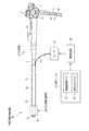
図1及び図2に示すように、内視鏡2は、超小型固体撮像素子(例えば、CCDセンサ)が内蔵され、大腸等の消化管内に挿入される挿入部3と、内視鏡2の把持及び挿入部3の操作に用いられる操作部4と、内視鏡2をプロセッサ装置、光源装置及び送気・送水装置(いずれも図示せず)に接続するためのユニバーサルコード5とから構成されている。[First Embodiment]
As shown in FIGS. 1 and 2, the endoscope 2 includes an ultra-small solid-state imaging device (for example, a CCD sensor), and includes an insertion portion 3 that is inserted into a digestive tract such as the large intestine, and the endoscope 2. The operation unit 4 is used to operate the gripping and insertion unit 3, and the
挿入部3は、CCDセンサが内蔵された硬質な先端部3aと、先端部3aの後端に連設された上下及び左右方向に湾曲自在な湾曲部3bと、湾曲部3bの後端に連設された可撓性を有する可撓部3cとからなる。 The insertion portion 3 includes a
挿入部3の先端部3aには、観察窓7、照明窓8a,8b、鉗子の先端が突出する鉗子出口9が設けられている。また、先端部3aには、観察窓7に向けて空気や洗浄水を噴射する噴射ノズル10が設けられている。 The
観察窓7は、CCDセンサの前方に形成され、CCDセンサに入射する撮影光を通す。照明窓8a,8bは、観察窓7を基準に対称な位置に2つ配されている。照明窓8a,8bは、光源装置から照射された照明光を、被検体内の観察している部分に向けて照射する。 The
鉗子出口9は、操作部4に設けられた鉗子入口13に連通している。この鉗子入口13には、注射針や高周波メスなどが先端に配された各種処置具(鉗子)が挿入される。 The forceps outlet 9 communicates with a
操作部4は、湾曲部3bを上下及び左右方向に湾曲させるアングルノブ14と、送気・送水や吸引等の各種操作の際に用いられる操作ボタン15とが設けられている。 The operation unit 4 is provided with an
操作部4には、ユニバーサルコード5が接続されている。このユニバーサルコード5には、送気・送水チューブ16と、撮像信号出力用ケーブル17と、ライトガイド18とが組み込まれている。送気・送水チューブ16は、一端が送気・送水装置に接続され、他端が噴射ノズル10に接続されており、送気・送水装置から供給された空気や洗浄水を噴射ノズル10に送る。撮像信号出力用ケーブル17は、一端がプロセッサ装置に接続され、他端がCCDセンサに接続されている。ライトガイド18は、一端が照明窓8a,8bに接続され、他端が光源装置に接続されており、光源装置から照射された照明光を照明窓8a,8bに導光する。 A
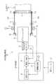
挿入部3の先端部3aには、消化管内で挿入部3を前進または後進させる内視鏡挿抜補助装置30の一部を構成する内視鏡挿抜補助具20が着脱可能に取り付けられている。この内視鏡挿抜補助具20は、モータ21によって駆動される。このモータ21は、連結ギア22を介してデフレンシャルギア23に接続されている。デフレンシャルギア23は、複数のギアからなる連結機構24を介して、内視鏡挿抜補助具20を推進させるための回転トルクを伝達する第1,第2トルクワイヤ25a,25bと連結されている。 An endoscope insertion / extraction assisting tool 20 constituting a part of an endoscope insertion /
デフレンシャルギア23は、周知の差動歯車機構であり、連結ギア22に噛合するリンクギア、リンクギアに固定された枠、枠に回転可能に取り付けられたピニオンギア、ピニオンギアに噛合するとともに第1,第2トルクワイヤ25a,25bに接続される第1トルクワイヤ用ギア及び第2トルクワイヤ用ギア(いずれも図示せず)等を有し、各トルクワイヤ25a,25bの回転差を吸収(補正)する。詳しくは、第1,第2トルクワイヤ25a,25bにかかる負荷が同じである場合には、ピニオンギアは回転せずに、第1,第2トルクワイヤ用ギアを同じ速度で回転し、負荷が異なる場合には、ピニオンギアが回転し、この回転により負荷の小さい一方に接続されたトルクワイヤ用ギアの回転速度を上昇させる。 The
各トルクワイヤ25a,25bは、保護シース19の内部に挿通されている。モータ21の駆動により、各トルクワイヤ25a,25bは保護シース19内で回動する。 The
モータ21は制御装置26により制御される。この制御装置26は操作ユニット27に接続されている。操作ユニット27は、内視鏡挿抜補助具20の前進・後進・停止の指示を入力するための駆動制御ボタン28と、内視鏡挿抜補助具20の移動速度を決定するための速度決定ボタン29とを備え、術者によって操作される。 The
挿入部3には、オーバーチューブ39が外嵌されており、保護シース19は、オーバーチューブ39と挿入部3との間に挿通されている。 An
内視鏡挿抜補助装置30には、第1トルクワイヤ25aにブレーキを掛ける第1ブレーキ31と、第2トルクワイヤ25bにブレーキを掛ける第2ブレーキ32とが設けられている。各ブレーキ31,32は、制御装置26により制御される。また、第1トルクワイヤ25aは、第1タコジェネレータ(以下、TG)33により回転速度が検出され、第2トルクワイヤ25bは、第2TG34により回転速度が検出される。各TG33,34は、回転速度に比例した直流電圧を発生し、この電圧は制御装置26に送られる。 The endoscope insertion /
制御装置26には、速度決定ボタン29の操作に基づいてモータ21の回転速度を指示する速度指示部36と、この速度指示部36で指示された回転速度に応じた電流をモータ21に付加する電流付加部37と、各トルクワイヤ25a,25bの断線を検出(判定)する断線検出部38が設けられている。この断線検出部38は、各TG33,34から送られてきた各直流電圧値の差が、予め設定された設定電圧値を超えたときに、各トルクワイヤ25a,25bのうちの直流電圧値が低い一方が断線されたことを検出する。制御装置26は、断線検出部38での検出結果に応じて、各ブレーキ31,32を駆動する。なお、各TG33,34からの各直流電圧値に基づいてモータ21の実際の回転速度を推定し、この推定回転速度を、速度指示部36で指示された回転速度と一致させるように電流付加部37を制御してもよい。 Based on the operation of the
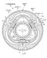
図3に示すように、内視鏡挿抜補助具20は、消化管の内壁に接触して、内視鏡2の挿入部3の挿入方向とは反対の反挿入方向に前進力を生じさせる回転体(トロイド)40を備えている。回転体40は、軸方向ADに沿う方向に循環を行うように支持筒(外筒)42に支持され、支持筒42を全周に亘って覆っている。図3における矢印は、循環の方向を示している。この回転体40は、柔軟性を有する材料(可撓性部材)により形成されており、具体的には、ポリ塩化ビニル、ポリアミド樹脂、フッ素樹脂、ウレタンやポリウレタンなどの生体適合プラスチックで形成されていることが好ましい。 As shown in FIG. 3, the endoscope insertion / extraction aid 20 rotates in contact with the inner wall of the digestive tract and generates a forward force in a direction opposite to the insertion direction of the insertion portion 3 of the endoscope 2. A body (toroid) 40 is provided. The rotating body 40 is supported by a support cylinder (outer cylinder) 42 so as to circulate in a direction along the axial direction AD, and covers the
図4〜図7に示すように、支持筒42は、軸方向ADに直交する方向の断面形状が、外周面では円形で内周面では略三角形(正三角形の各角が湾曲されて丸まった形状)の管状体であって、回転体40が巻き付けられている。 As shown in FIGS. 4 to 7, the
回転体40は、両端のある状態で支持筒42の形状に沿って180°折り曲げられて支持筒42に巻付けられた後、両端が熱溶着等により接着されて、無端状態となる。 The rotating body 40 is bent 180 ° along the shape of the
支持筒42の前端及び後端それぞれには、回転体40の180°折り曲げられた部分に接触するリング状の接触体44が取り付けられている。接触体44は、回転体40が滑らかに循環するような素材(例えば、ナイロン)から構成されている。なお、接触体44は、ナイロンに限らず、PEEK、テフロン(登録商標)などの摺動性の高い材料であればよい。 A ring-shaped
支持筒42の内周面が直線部分である3箇所には、それぞれ開口42aが形成されている。これらの各開口42aには、それぞれ回転体40を循環可能となるように支持するローラユニット45が取り付けられている。ローラユニット45は、2枚の支持プレート50の間に、軸方向ADに沿って順に第1〜第3支持ローラ51〜53が回転可能に取り付けられている。なお、各ローラ51〜53を、支持筒42自体に回転可能に取り付けてもよい。また、ローラユニット45を取り付ける箇所は3箇所に限らず、その数は適宜変更可能である。
回転体40は、内表面40aが各支持ローラ51〜53に接触する。回転体40は、各支持ローラ51〜53に接触する部分が、他の部分よりも厚くされ、他の部分よりも剛性が高くなっている。 As for the rotary body 40, the
各支持ローラ51〜53には、それぞれ中央部に溝部51a〜53aが形成されている。回転体40の内表面40aには、線状突起40cが3個形成されている。この線状突起40cは、全周に亘って形成されている。線状突起40cは、溝部51a〜53aに摺動自在に係合しており、回転体40が周方向CDに回転することを防止している。同様に、支持筒42には、線状突起40cが摺動自在に係合する溝部42bが形成され、接触体44には、線状突起40cが摺動自在に係合する溝部44aが形成されている。なお、溝部42b,44a及び溝部51a〜53aと、線状突起40cとの間には、両者間の摺動性を高めるために、潤滑剤が塗布されている。 Each of the
支持筒42の内部には、内視鏡2の先端部3aが装着される円筒状の装着筒61と、装着筒61の外側に回動可能に支持された伝達ギア62と、装着筒61及び伝達ギア62を収納する収納筒63とが配されている。 Inside the
収納筒63の後端には、蓋部材66が取り付けられている。収納筒63の先端には、消化管の内壁の侵入を防止する前ストッパ67が取り付けられ、同様に、蓋部材66には、後ストッパ68が取り付けられている。 A
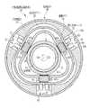
伝達ギア62は、円筒状に形成され、装着筒61に外嵌されて軸方向ADを中心に回転する。伝達ギア62には、軸方向ADを中心軸とした螺旋状のウォームギア71と、周方向に複数のギアが配列された周歯ギア72とが形成されている。この周歯ギア72は、伝達ギア62の後端部に形成されている。周歯ギア72には、第1トルクワイヤ25aに接続された第1回転ギア74aと、第2トルクワイヤ25bに接続された第2回転ギア74bとが噛合している。各回転ギア74a,74bは、各トルクワイヤ25a,25bにより回転され、この回転により周歯ギア72を回転して、伝達ギア62を回転させる。各トルクワイヤ25a,25bは、後ストッパ68に形成された挿通孔(図示せず)に挿通されている。 The
収納筒63は、略三角形(正三角形の各角が湾曲されて丸まった形状)の筒状に形成され、支持筒42と異なる軸位置となるように配されている。収納筒63の3個の直線部分には、それぞれ開口63aが形成されている。これら3個の開口63aには、それぞれ駆動ギア76が2個ずつ配されている。駆動ギア76は、収納筒63に形成された取付リブ63bに回転可能に取り付けられている。各駆動ギア76は、第1支持ローラ51と第2支持ローラ52との間と、第2支持ローラ52と第3支持ローラ53との間とに配されている。 The
各駆動ギア76は、伝達ギア62のウォームギア71に噛合するとともに、回転体40の外表面40bに接触し、第1〜第3支持ローラ51〜53との間で回転体40を挟持する。各駆動ギア76は、支持筒42の径方向において、各支持ローラ51〜53とオーバーラップしており、各支持ローラ51〜53と各駆動ギア76との間では、回転体40は波状に湾曲されている。 Each
収納筒63の前面には、開口63cが形成され、この開口63cには、装着筒61の先端部が挿入されている。 An
前ストッパ67は、開口63cに挿入されるリング状の挿入部67aと、消化管の内壁が内視鏡挿抜補助具20の内部に侵入するのを防止するストッパ部67bとからなる。ストッパ部67bは、挿入部67aからの距離に従って径が増加するすり鉢形状となっており、その断面形状は、支持筒42の内周面と同様な形状(略三角形)で、支持筒42よりも一回り小さい。 The
蓋部材66は、収納筒63と同一の形状(略三角形)で形成され、装着筒61の挿入孔61aと連通する開口66aが形成されている。また、蓋部材66には、各回転ギア74a,74bを回動自在に収容する凹部66bが2個形成されている。各凹部66bに収容された各回転ギア74a,74bは、伝達ギア62の周歯ギア72に噛合している。各トルクワイヤ25a,25bは、蓋部材66に形成された孔(図示せず)を介して各回転ギア74a,74bに接続されている。 The
後ストッパ68は、前ストッパ67と同様な構成であり、蓋部材66の開口66aに挿入されるリング状の挿入部68aと、ストッパ部68bとからなる。 The
次に、内視鏡挿抜補助具20の作用について図8のフローチャートを用いて説明する。先ず、内視鏡2の先端部3aを、装着筒61の挿入孔61aに嵌入させて、先端部3aに内視鏡挿抜補助具20を装着する(ステップ(以下、S)1)。次に、プロセッサ装置、光源装置、操作ユニット27等の電源をオンして、検査準備を行い(S2)、この検査準備が完了した後、内視鏡2の先端部3aを患者の消化管内に挿入する(S3)。 Next, the operation of the endoscope insertion / extraction aid 20 will be described using the flowchart of FIG. First, the
先端部3aが消化管内の所定位置、例えばS状結腸の手前まで進められた後、操作ユニット27の速度決定ボタン29が操作される(S4)と、内視鏡挿抜補助具20の移動(挿入または抜去)速度が決定される(S5)。そして、駆動制御ボタン28が操作されて前進(挿入)指示が入力される(S6)と、制御装置26の速度指示部36は、決定された移動速度に応じたモータ21の回転速度を電流付加部37に指示する(S7)。なお、内視鏡挿抜補助具20の移動速度は、先端部3aを消化管内に挿入する前に決定しておいてもよい。 After the
電流付加部37は、指示された回転速度に応じた電流をモータ21に付加する(S8)。この電流付加によりモータ21が駆動され、連結ギア22、デフレンシャルギア23、連結機構24を介して、第1,第2トルクワイヤ25a,25bが所定方向に回転される。この第1,第2トルクワイヤ25a,25bの回転に伴う各回転ギア74a,74bの回転により、各回転ギア74a,74bに噛合している周歯ギア72が回転し、伝達ギア62が回転する。 The current adding
伝達ギア62が回転すると、伝達ギア62のウォームギア71に噛合している駆動ギア76が回転する。この駆動ギア76の回転により、駆動ギア76と第1〜第3支持ローラ51〜53との間で挟持されている回転体40が、図4の矢印で示す方向に駆動(回転)する(S9)。この駆動により、支持筒42の外側に位置し、消化管の内壁と接触する回転体40の各外表面40bは、反挿入方向に移動する。このとき、支持筒42の内部に位置する回転体40の各外表面40bは、挿入方向に移動し、回転体40は循環する。 When the
回転体40は、消化管の内壁に接触しており、循環により、先端部3aの挿入方向とは反対の反挿入方向に前進力を生じさせる。内視鏡挿抜補助具20は、この前進力で消化管の内壁を前方から後方に手繰り寄せることにより、内視鏡2の先端部3aを消化管の内壁に沿って前進させる(S10)。一方、内視鏡挿抜補助具20を反挿入方向に推進(後進)させる場合には、回転体40は、上記とは逆向きに循環する。 The rotating body 40 is in contact with the inner wall of the digestive tract, and generates a forward force in the counter-insertion direction opposite to the insertion direction of the
操作ユニット27の速度決定ボタン29が操作されて速度変更が指示される(S11でY)と、変更後の移動速度に応じたモータ21の回転速度が速度指示部36から電流付加部37に指示される(S7)。そして、電流付加部37は、指示された回転速度に応じた電流をモータ21に付加する(S8)。これにより、モータ21の回転速度が変更されて、第1,第2トルクワイヤ25a,25bの回転速度が変更され、内視鏡挿抜補助具20の移動速度が変更される。また、操作ユニット27の駆動制御ボタン28が操作されて後進指示が入力されると、モータ21が逆回転されて各トルクワイヤ25a,25bが逆回転され、内視鏡挿抜補助具20が後進する。さらに、駆動制御ボタン28の操作により停止指示が入力されると、モータ21の回転が停止されて各トルクワイヤ25a,25bの回転が停止され、内視鏡挿抜補助具20が停止する。以上の操作を適宜行うことにより、内視鏡2の先端部3aを消化管の所望の位置まで推進させることができる。 When the
光源装置からの光は、ライトガイド18、照明窓8a,8bを通って、消化管内に照射される。先端部3aに内蔵されたCCDは、消化管内を撮影して撮像信号を出力する。この撮像信号は、撮像信号出力用ケーブル17、ユニバーサルコード5を介してプロセッサ装置に入力され、モニタ(図示せず)に表示される。術者は、モニタを通じて消化管内を観察する。 Light from the light source device is irradiated into the digestive tract through the
観察中に患部を発見した場合には、この患部の処置に適した処置具を、鉗子入口13に挿入して鉗子出口9から突出させ、患部を処置する。 When an affected part is found during observation, a treatment tool suitable for the treatment of the affected part is inserted into the
観察窓7を洗浄する場合には、操作ボタン15を操作して、送気・送水装置から供給された空気や洗浄水を、送気・送水チューブ16を介して噴射ノズル10へ送る。この供給された空気や洗浄水は、噴射ノズル10から観察窓7に向けて噴射され、観察窓7に付着した汚れが払拭される。 When cleaning the
第1TG33は第1トルクワイヤ25aの回転速度を検出し、第2TG34は第2トルクワイヤ25bの回転速度を検出し(S12)、各TG33,34は、検出した回転速度に比例した直流電圧を発生して制御装置26に送る(S13)。 The
制御装置26の断線検出部38は、各TG33,34から送られてきた直流電圧値に基づいて、各トルクワイヤ25a,25bの断線を検出する。 The
第1トルクワイヤ25aが断線した場合、第1トルクワイヤ25aにかかる負荷が小さくなり、第2トルクワイヤ25bにかかる負荷が大きくなるため、デフレンシャルギア23の第1トルクワイヤ用ギアと第2トルクワイヤ用ギアとの間に配されたピニオンギアが回転する。このピニオンギアが回転した分だけ第1トルクワイヤ用ギアは余分に回転され、第1トルクワイヤ25aの回転速度が上昇する。このデフレンシャルギア23の特性を利用して、第1TG33からの電圧値(以下、第1電圧値)が、第2TG34からの電圧値(以下、第2電圧値)よりも高く(S14でY)、第1電圧値と第2電圧値との差(以下、差分電圧値)が設定電圧値を超えた場合(S15でY)、断線検出部38は、第1電圧値に係る第1トルクワイヤ25aが断線したことを検出する(S16)。 When the
断線検出部38で第1トルクワイヤ25aの断線が検出されると、制御装置26は、内視鏡挿抜補助具20の駆動に制限のない通常モードから、後進のみを行う抜去モードに切り換える。この抜去モードでは、制御装置26は、第1ブレーキ31を駆動して第1トルクワイヤ25aにブレーキを掛ける(S17)。第1トルクワイヤ25aにブレーキが掛かると、第1トルクワイヤ用ギアの回転が止まり、ピニオンギアが回転する。このピニオンギアが回転した分だけ第2トルクワイヤ用ギアは余分に回転され、第2トルクワイヤ25bの回転速度が上昇する(S18)。これにより、第1トルクワイヤ25a断線時にも、内視鏡挿抜補助具20が確実に駆動される。 When the
抜去モードでは、制御装置26は、モータ21を逆回転して第2トルクワイヤ25bを逆回転し(S19)、内視鏡挿抜補助具20を後進させて内視鏡2の先端部3aを後進させる(S20)。これにより、第1トルクワイヤ25a断線時にも、内視鏡挿抜補助具20が確実に消化管外に抜き出される。なお、抜去モードでは、速度決定ボタン29の操作により内視鏡挿抜補助具20の移動速度を決定することはできるが、内視鏡挿抜補助具20を前進させる操作は無効化され、前進させることはできない。 In the extraction mode, the control device 26 reversely rotates the
一方、第2電圧値が第1電圧値よりも高く(S14でN、S21でY)、差分電圧値が設定電圧値を超えた場合(S22でY)、断線検出部38は、第2電圧値に係る第2ルクワイヤ25bが断線したことを検出する(S23)。 On the other hand, when the second voltage value is higher than the first voltage value (N in S14, Y in S21) and the differential voltage value exceeds the set voltage value (Y in S22), the
断線検出部38で第2トルクワイヤ25bの断線が検出されると、制御装置26は、通常モードから抜去モードに切り換えるとともに、第2ブレーキ32を駆動して第2トルクワイヤ25bにブレーキを掛けて(S17)、第1トルクワイヤ25aの回転速度を上げる(S18)。抜去モードでは、モータ21を逆回転して第1トルクワイヤ25aを逆回転し(S19)、内視鏡2の先端部3aを後進させる(S20)。 When the
[第2実施形態]
図9に示す第2実施形態では、ワイヤ断線検出時には、ワイヤ回転速度を低速にする。なお、第1実施形態のものと同様の構成部材には同一の符号を付し、その詳細な説明を省略する。[Second Embodiment]
In the second embodiment shown in FIG. 9, the wire rotation speed is set to a low speed when wire breakage is detected. In addition, the same code | symbol is attached | subjected to the structural member similar to the thing of 1st Embodiment, and the detailed description is abbreviate | omitted.
図9に示すように、内視鏡2の先端部3aに内視鏡挿抜補助具20を装着し(S101)、プロセッサ装置、光源装置、操作ユニット27等の電源をオンして、検査準備を行い(S102)、この検査準備が完了した後、内視鏡2の先端部3aを患者の消化管内に挿入する(S103)。以下(S104)〜(S115)は、第1実施形態の(S4)〜(S15)と同様のステップであるため、説明を省略する。 As shown in FIG. 9, the endoscope insertion / extraction tool 20 is attached to the
断線検出部38で第1トルクワイヤ25aの断線が検出される(S116)と、制御装置26は、通常モードから、通常モードよりも低速での前進及び後進を行う低速モードに切り換えるとともに、第1トルクワイヤ25aにブレーキを掛ける(S117)。低速モードでは、速度指示部36は、予め設定された回転速度以下の数値を電流付加部37に指示して(S118)、モータ21を低速で回転して第2トルクワイヤ25bを低速回転する(S119)。第2トルクワイヤ25bの低速回転により、内視鏡挿抜補助具20が低速前進し、内視鏡2の先端部3aが低速前進する(S120)。これにより、高速で回転するときに比べて、第2トルクワイヤ25bが断線する危険性が低下する。なお、低速モードでは、内視鏡挿抜補助具20の移動方向を選択することはできるが、速度決定ボタン29による移動速度の決定操作は無効化され、移動速度を変更することはできない。 When the
第2電圧値が第1電圧値よりも低く(S114でN、S121でY)、差分電圧値が設定電圧値を超えた場合(S122でY)、断線検出部38は、第2電圧値に係る第2ルクワイヤ25bが断線したことを検出する(S123)。 When the second voltage value is lower than the first voltage value (N in S114, Y in S121) and the differential voltage value exceeds the set voltage value (Y in S122), the
断線検出部38で第2トルクワイヤ25bの断線が検出されると、制御装置26は、通常モードから低速モードに切り換えるとともに、第2ブレーキ32を駆動して第2トルクワイヤ25bにブレーキを掛ける(S117)。低速モードでは、速度指示部36は、設定回転速度以下の回転速度を電流付加部37に指示し(S118)、モータ21を低速で回転して第1トルクワイヤ25aを低速回転する(S119)。第1トルクワイヤ25aの低速回転により、内視鏡挿抜補助具20が低速前進し、内視鏡2の先端部3aが低速前進する(S120)。 When the
[第3実施形態]
図10に示す第2実施形態では、ワイヤ断線検出時には、モータ21に付加する電流の最大値を下げる。なお、第1実施形態のものと同様の構成部材には同一の符号を付し、その詳細な説明を省略する。[Third Embodiment]
In the second embodiment shown in FIG. 10, the maximum value of the current applied to the
図10に示すように、内視鏡2の先端部3aに内視鏡挿抜補助具20を装着し(S201)、プロセッサ装置、光源装置、操作ユニット27等の電源をオンして、検査準備を行い(S202)、この検査準備が完了した後、内視鏡2の先端部3aを患者の消化管内に挿入する(S203)。以下(S204)〜(S215)は、第1実施形態の(S4)〜(S15)と同様のステップであるため、説明を省略する。 As shown in FIG. 10, the endoscope insertion / removal aid 20 is attached to the
断線検出部38で第1トルクワイヤ25aの断線が検出される(S216)と、制御装置26は、通常モードから、通常モードよりもモータ21に付加する電流の最大値を下げる低電流モードに切り換えるとともに、第1トルクワイヤ25aにブレーキを掛ける(S217)。低電流モードでは、電流付加部37は、モータ21に付加する電流の最大値を通常モード時よりも下げ(S218)、モータ21を低速で回転して第2トルクワイヤ25bを低速回転する(S219)。第2トルクワイヤ25bの低速回転により、内視鏡挿抜補助具20が低速前進し、内視鏡2の先端部3aが低速前進する(S220)。これにより、高速で回転するときに比べて、第2トルクワイヤ25bが断線する危険性が低下する。なお、低電流モードでは、内視鏡挿抜補助具20の移動方向を選択することはできるが、速度決定ボタン29による移動速度の決定操作は無効化され、移動速度を変更することはできない。 When disconnection of the
第2電圧値が第1電圧値よりも低く(S214でN、S221でY)、差分電圧値が設定電圧値を超えた場合(S222でY)、断線検出部38は、第2電圧値に係る第2ルクワイヤ25bが断線したことを検出する(S223)。 When the second voltage value is lower than the first voltage value (N in S214, Y in S221) and the differential voltage value exceeds the set voltage value (Y in S222), the
断線検出部38で第2トルクワイヤ25bの断線が検出されると、制御装置26は、通常モードから低電流モードに切り換えるとともに、第2ブレーキ32を駆動して第2トルクワイヤ25bにブレーキを掛ける(S217)。低電流モードでは、電流付加部37は、モータ21に付加する電流の最大値を通常モード時よりも下げ(S218)、モータ21を低速で回転して第1トルクワイヤ25aを低速回転する(S119)。第1トルクワイヤ25aの低速回転により、内視鏡挿抜補助具20が低速前進し、内視鏡2の先端部3aが低速前進する(S220)。 When the
なお、上記第1〜第3実施形態を組み合わせることで、ワイヤ断線検出に応じて、低速での後進のみを行う低速後進モードや、低電流での後進のみを行う低電流後進モードに切り換えるようにしてもよい。 In addition, by combining the first to third embodiments, it is possible to switch to a low-speed reverse mode that performs only reverse at low speed or a low-current reverse mode that performs only reverse at a low current in accordance with the detection of wire breakage. May be.
また、上記実施形態では、第1,第2トルクワイヤそれぞれの回転速度を検出し、その差が設定値を超えたときに、ワイヤが断線されたと判断しているが、ワイヤの断線検出方法は適宜変更可能である。 In the above embodiment, the rotational speeds of the first and second torque wires are detected, and when the difference exceeds a set value, it is determined that the wire is disconnected. It can be changed as appropriate.
さらに、上記実施形態では、支持筒を円形としているが、これに限定されることなく、三角形、四角形等のいかなる多角形としてもよい。 Furthermore, in the said embodiment, although the support cylinder is circular, it is not limited to this, It is good also as any polygons, such as a triangle and a quadrangle.
また、上記実施形態では、支持筒を全周に亘って覆う回転体により内視鏡を前進・後進させているが、支持筒の周方向の一部を覆う複数の無端ベルトにより内視鏡を前進・後進させてもよい。 In the above-described embodiment, the endoscope is moved forward and backward by a rotating body that covers the entire circumference of the support cylinder. However, the endoscope is moved by a plurality of endless belts that cover a part of the circumferential direction of the support cylinder. You may move forward and backward.
さらに、上記実施形態では、伝達ギアのウォームギアによって駆動ギアを回転し、この駆動ギアにより回転体を駆動しているが、ウォームギアにより無端ベルトを直接駆動してもよい。なお、駆動ギアを設ける場合と設けない場合とで、前進・後進させるためのウォームギアの回転方向が逆となるため、操作ユニットによりなされる前進・後進指示と動力源によるトルクワイヤの回転方向の関係を変更する必要がある。 Furthermore, in the above embodiment, the drive gear is rotated by the worm gear of the transmission gear and the rotating body is driven by this drive gear, but the endless belt may be directly driven by the worm gear. Note that the rotation direction of the worm gear for moving forward / reverse is reversed depending on whether the drive gear is provided or not, so the relationship between the forward / reverse instruction issued by the operation unit and the rotation direction of the torque wire by the power source Need to be changed.
また、上記実施形態は、本発明を医療診断用の内視鏡に適用したものであるが、本発明は医療診断用途に限られず、工業用等のその他の内視鏡やプローブ等に適用することも可能である。 Moreover, although the said embodiment applies this invention to the endoscope for medical diagnosis, this invention is not restricted to a medical diagnostic use, It applies to other endoscopes, probes, etc. for industrial use etc. It is also possible.
2 内視鏡
20 内視鏡挿抜補助具
21 モータ
22 連結ギア
23 デフレンシャルギア
25a,25b 第1,第2トルクワイヤ
26 制御装置
30 内視鏡挿抜補助装置
31,32 第1,第2ブレーキ
33,34 第1,第2TG
36 速度指示部
37 電流付加部
38 断線検出部
40 回転体
42 支持筒(外筒)
51〜53 第1〜第3支持ローラ
61 装着筒
61b 挿入孔
62 伝達ギア
71 ウォームギア
74a,74b 第1,第2回転ギア
76 駆動ギア2 Endoscope 20 Endoscope insertion /
36
51 to 53 First to
Claims (10)
Translated fromJapanese前記各回転ギアに接続される回転可能な複数のワイヤと、
前記各ワイヤそれぞれに接続され、前記各ワイヤにかかる負荷に応じて前記各ワイヤの回転速度を変えるデフレンシャルギアと、
前記デフレンシャルギア及び各ワイヤを介して前記各回転ギアを回転するモータと、
前記モータの駆動を制御するモータ制御手段と、
前記各ワイヤそれぞれの断線を検出する断線検出手段と、
前記各ワイヤにブレーキを掛ける複数のブレーキ手段と、
前記断線検出手段によりワイヤ断線が検出されたときに、前記ブレーキ手段を駆動して前記断線が検出されたワイヤにブレーキを掛けて、前記デフレンシャルギアにより他のワイヤの回転速度を上昇させるブレーキ制御手段と、
を備えることを特徴とする内視鏡挿抜補助装置。An insertion hole into which the distal end portion of the endoscope is inserted along the axial direction is formed, and the mounting tube is attached to the distal end portion so as to be in the same axial direction as the distal end portion, and is rotated to the outside of the mounting tube. A cylindrical transmission gear that can be attached, a plurality of rotation gears that mesh with and rotate with the transmission gear, an outer cylinder that is arranged outside the transmission gear, and the mounting cylinder that is wound around the outer cylinder, A circulation body that is supported by the outer cylinder so as to circulate along the axial direction, and a circulation drive unit that circulates and drives the circulation body using the rotation of the transmission gear. An endoscope insertion / removal aid for assisting insertion of the endoscope into and removal from the subject; and
A plurality of rotatable wires connected to each rotating gear;
A differential gear that is connected to each of the wires and changes the rotational speed of the wires in accordance with a load applied to the wires;
A motor for rotating the rotating gears via the differential gear and the wires;
Motor control means for controlling the driving of the motor;
Disconnection detecting means for detecting disconnection of each of the wires;
A plurality of brake means for braking each wire;
When the wire breakage is detected by the breakage detection unit, the brake unit is driven to brake the wire where the wire breakage is detected, and the differential gear increases the rotation speed of the other wire. Means,
An endoscope insertion / extraction assisting device comprising:
前記循環駆動部は、
前記伝達ギアに設けられたウォームギアと、
前記ウォームギアに噛合するとともに、前記複数の支持ローラとの間で前記循環体を挟持して前記循環体を循環駆動する複数の駆動ギアと、
を備えることを特徴とする請求項1ないし9いずれか1つ記載の内視鏡挿抜補助装置。A plurality of support rollers that are rotatably attached to the outer cylinder and that are in contact with the inner peripheral surface of the circulation body and support the circulation body in a circulatory manner,
The circulation drive unit is
A worm gear provided in the transmission gear;
A plurality of drive gears that mesh with the worm gear and that circulate and drive the circulation body by sandwiching the circulation body between the plurality of support rollers;
The endoscope insertion / extraction assisting device according to any one of claims 1 to 9, further comprising:
Priority Applications (2)
| Application Number | Priority Date | Filing Date | Title |
|---|---|---|---|
| JP2011117067AJP2012245052A (en) | 2011-05-25 | 2011-05-25 | Device for assisting insertion/extraction of endoscope |
| US13/479,812US20120302831A1 (en) | 2011-05-25 | 2012-05-24 | Guide apparatus for endoscope |
Applications Claiming Priority (1)
| Application Number | Priority Date | Filing Date | Title |
|---|---|---|---|
| JP2011117067AJP2012245052A (en) | 2011-05-25 | 2011-05-25 | Device for assisting insertion/extraction of endoscope |
Publications (1)
| Publication Number | Publication Date |
|---|---|
| JP2012245052Atrue JP2012245052A (en) | 2012-12-13 |
Family
ID=47219681
Family Applications (1)
| Application Number | Title | Priority Date | Filing Date |
|---|---|---|---|
| JP2011117067AWithdrawnJP2012245052A (en) | 2011-05-25 | 2011-05-25 | Device for assisting insertion/extraction of endoscope |
Country Status (2)
| Country | Link |
|---|---|
| US (1) | US20120302831A1 (en) |
| JP (1) | JP2012245052A (en) |
Cited By (5)
| Publication number | Priority date | Publication date | Assignee | Title |
|---|---|---|---|---|
| JP2016054841A (en)* | 2014-09-08 | 2016-04-21 | オリンパス株式会社 | Insertion device |
| WO2016104073A1 (en)* | 2014-12-25 | 2016-06-30 | オリンパス株式会社 | Insertion device |
| WO2017183598A1 (en)* | 2016-04-18 | 2017-10-26 | オリンパス株式会社 | Control device and insertion device |
| JP6230767B1 (en)* | 2016-06-13 | 2017-11-15 | オリンパス株式会社 | Insertion tool and insertion device |
| WO2017217055A1 (en)* | 2016-06-13 | 2017-12-21 | オリンパス株式会社 | Insertion tool and insertion apparatus |
Families Citing this family (6)
| Publication number | Priority date | Publication date | Assignee | Title |
|---|---|---|---|---|
| US9693676B2 (en)* | 2013-05-10 | 2017-07-04 | J. Mathieu Massicotte | Toroidal balloon-driven vehicle |
| CN108135451B (en)* | 2015-10-28 | 2020-02-21 | 奥林巴斯株式会社 | Insert device |
| DE112017002950T5 (en)* | 2016-06-13 | 2019-02-28 | Olympus Corporation | Introduction device, Ansetzwerkzeug and drive power transmission unit |
| RU2666261C2 (en)* | 2016-11-03 | 2018-09-06 | ООО "Медикрон Групп" | Modular video-endoscopic system |
| CN114212614B (en)* | 2021-12-31 | 2023-08-11 | 中国科学院光电技术研究所 | Wire coiling mechanism |
| GB2627981A (en)* | 2023-03-09 | 2024-09-11 | Keymed Medical & Industrial Equipment Ltd | Medical scope accessory |
Family Cites Families (5)
| Publication number | Priority date | Publication date | Assignee | Title |
|---|---|---|---|---|
| US5571114A (en)* | 1994-07-13 | 1996-11-05 | Devanaboyina; Udaya-Sankar | Mechanism to advance or withdraw objects in lumens or cavities of mammals |
| US7174240B2 (en)* | 2001-10-19 | 2007-02-06 | Cardiovascular Systems, Inc. | Control system for rotational angioplasty device |
| US7736300B2 (en)* | 2003-04-14 | 2010-06-15 | Softscope Medical Technologies, Inc. | Self-propellable apparatus and method |
| US20090221914A1 (en)* | 2005-09-14 | 2009-09-03 | Acist Medical Systems, Inc. | Medical Fluid Injection System |
| JP4521363B2 (en)* | 2006-02-17 | 2010-08-11 | 昌純 高田 | Self-propelled colonoscopy |
- 2011
- 2011-05-25JPJP2011117067Apatent/JP2012245052A/ennot_activeWithdrawn
- 2012
- 2012-05-24USUS13/479,812patent/US20120302831A1/ennot_activeAbandoned
Cited By (10)
| Publication number | Priority date | Publication date | Assignee | Title |
|---|---|---|---|---|
| JP2016054841A (en)* | 2014-09-08 | 2016-04-21 | オリンパス株式会社 | Insertion device |
| WO2016104073A1 (en)* | 2014-12-25 | 2016-06-30 | オリンパス株式会社 | Insertion device |
| JP6017740B1 (en)* | 2014-12-25 | 2016-11-02 | オリンパス株式会社 | Insertion device and control device thereof |
| US10314464B2 (en) | 2014-12-25 | 2019-06-11 | Olympus Corporation | Insertion apparatus |
| WO2017183598A1 (en)* | 2016-04-18 | 2017-10-26 | オリンパス株式会社 | Control device and insertion device |
| JP6271110B1 (en)* | 2016-04-18 | 2018-01-31 | オリンパス株式会社 | Control device and insertion device |
| US10588488B2 (en) | 2016-04-18 | 2020-03-17 | Olympus Corporation | Controller and insertion apparatus |
| JP6230767B1 (en)* | 2016-06-13 | 2017-11-15 | オリンパス株式会社 | Insertion tool and insertion device |
| WO2017217055A1 (en)* | 2016-06-13 | 2017-12-21 | オリンパス株式会社 | Insertion tool and insertion apparatus |
| US11116387B2 (en) | 2016-06-13 | 2021-09-14 | Olympus Corporation | Insertion device and endoscope |
Also Published As
| Publication number | Publication date |
|---|---|
| US20120302831A1 (en) | 2012-11-29 |
Similar Documents
| Publication | Publication Date | Title |
|---|---|---|
| JP2012245052A (en) | Device for assisting insertion/extraction of endoscope | |
| US20130172679A1 (en) | Endoscope insertion assisting device | |
| US9107576B2 (en) | Endoscope insertion assisting device | |
| JP5174140B2 (en) | Endoscope insertion aid | |
| JP2014068817A (en) | Condition visually confirming device for endoscope | |
| JP2013153819A (en) | Propulsion assisting apparatus for endoscope | |
| JP5628261B2 (en) | Medical drive | |
| JP2012029865A (en) | Endoscope mounting fixture | |
| JP5284570B2 (en) | Rotating self-propelled endoscope system | |
| JP2011235005A (en) | Endoscope mounting implement | |
| JP2012245051A (en) | Device for assisting insertion of endoscope | |
| JP2012029864A (en) | Endoscope mounting fixture | |
| JP2013236747A (en) | Driving force transmission device for endoscope and endoscope auxiliary thrust device equipped with the same | |
| JP2013123601A (en) | Device for assisting endoscope propulsion | |
| JP2007307241A (en) | Rotating self-propelled endoscope and rotating self-propelled endoscope apparatus | |
| JP2013208170A (en) | Endoscope propulsion assist device | |
| JP2012191980A (en) | Endoscope mounting fixture | |
| JP5179601B2 (en) | Endoscope insertion assist device | |
| JP5179600B2 (en) | Endoscope insertion assist device | |
| JP5236035B2 (en) | Endoscope insertion aid | |
| JP4813630B2 (en) | Endoscope device | |
| US20120238804A1 (en) | Propelling device and self-propellable endoscope | |
| JP2012050514A (en) | Self-propelled unit | |
| US20120046523A1 (en) | Self propelling device | |
| US20140012086A1 (en) | Self-propelling device |
Legal Events
| Date | Code | Title | Description |
|---|---|---|---|
| A300 | Application deemed to be withdrawn because no request for examination was validly filed | Free format text:JAPANESE INTERMEDIATE CODE: A300 Effective date:20140805 |