JP2012236083A - Automatic neural stimulation modulation based on activity - Google Patents
Automatic neural stimulation modulation based on activityDownload PDFInfo
- Publication number
- JP2012236083A JP2012236083AJP2012197413AJP2012197413AJP2012236083AJP 2012236083 AJP2012236083 AJP 2012236083AJP 2012197413 AJP2012197413 AJP 2012197413AJP 2012197413 AJP2012197413 AJP 2012197413AJP 2012236083 AJP2012236083 AJP 2012236083A
- Authority
- JP
- Japan
- Prior art keywords
- activity
- stimulation
- neural stimulation
- monitor
- modulator
- Prior art date
- Legal status (The legal status is an assumption and is not a legal conclusion. Google has not performed a legal analysis and makes no representation as to the accuracy of the status listed.)
- Granted
Links
- 230000000638stimulationEffects0.000titleclaimsabstractdescription379
- 230000000694effectsEffects0.000titleclaimsabstractdescription200
- 230000001537neural effectEffects0.000titleclaimsabstractdescription197
- 230000008859changeEffects0.000claimsabstractdescription16
- 230000000747cardiac effectEffects0.000claimsdescription109
- 230000036772blood pressureEffects0.000claimsdescription69
- 210000002216heartAnatomy0.000claimsdescription64
- 210000005036nerveAnatomy0.000claimsdescription58
- 230000027288circadian rhythmEffects0.000claimsdescription39
- 230000033001locomotionEffects0.000claimsdescription23
- 230000004872arterial blood pressureEffects0.000claimsdescription21
- 210000003403autonomic nervous systemAnatomy0.000claimsdescription20
- 230000000241respiratory effectEffects0.000claimsdescription19
- 238000009423ventilationMethods0.000claimsdescription19
- 230000004044responseEffects0.000claimsdescription18
- 230000007383nerve stimulationEffects0.000claimsdescription11
- 210000003205muscleAnatomy0.000claimsdescription9
- 230000035488systolic blood pressureEffects0.000claimsdescription9
- 230000035487diastolic blood pressureEffects0.000claimsdescription8
- 238000005259measurementMethods0.000claimsdescription6
- 230000006461physiological responseEffects0.000claimsdescription5
- 230000036387respiratory rateEffects0.000claimsdescription5
- 230000009471actionEffects0.000claimsdescription4
- 238000002567electromyographyMethods0.000claimsdescription4
- 238000005516engineering processMethods0.000claimsdescription4
- 230000008035nerve activityEffects0.000claimsdescription4
- 230000035485pulse pressureEffects0.000claimsdescription3
- 238000013507mappingMethods0.000claims1
- 238000002560therapeutic procedureMethods0.000abstractdescription78
- 108091008698baroreceptorsProteins0.000description129
- 210000001774pressoreceptorAnatomy0.000description129
- 230000035581baroreflexEffects0.000description102
- 238000000034methodMethods0.000description79
- 210000001147pulmonary arteryAnatomy0.000description45
- 230000006870functionEffects0.000description44
- 206010020772HypertensionDiseases0.000description37
- 208000010125myocardial infarctionDiseases0.000description33
- 230000008569processEffects0.000description32
- 230000029058respiratory gaseous exchangeEffects0.000description28
- 206010019280Heart failuresDiseases0.000description21
- 210000000577adipose tissueAnatomy0.000description20
- 230000004936stimulating effectEffects0.000description20
- 210000001326carotid sinusAnatomy0.000description18
- 230000006854communicationEffects0.000description18
- 238000004891communicationMethods0.000description18
- 230000036279refractory periodEffects0.000description17
- 230000033764rhythmic processEffects0.000description17
- 230000002889sympathetic effectEffects0.000description17
- 210000002376aorta thoracicAnatomy0.000description16
- 210000004204blood vesselAnatomy0.000description16
- 238000007726management methodMethods0.000description15
- 230000002861ventricularEffects0.000description15
- 230000001746atrial effectEffects0.000description12
- 230000002829reductive effectEffects0.000description12
- 210000005241right ventricleAnatomy0.000description12
- 210000002820sympathetic nervous systemAnatomy0.000description12
- 230000009885systemic effectEffects0.000description12
- 210000001186vagus nerveAnatomy0.000description12
- 230000007423decreaseEffects0.000description11
- 230000002411adverseEffects0.000description10
- 230000002503metabolic effectEffects0.000description10
- 210000001002parasympathetic nervous systemAnatomy0.000description10
- 230000009467reductionEffects0.000description10
- 238000011282treatmentMethods0.000description10
- 230000003247decreasing effectEffects0.000description9
- 238000007634remodelingMethods0.000description9
- 210000001640nerve endingAnatomy0.000description8
- 230000001766physiological effectEffects0.000description8
- 230000011514reflexEffects0.000description8
- 230000001133accelerationEffects0.000description7
- 230000004913activationEffects0.000description7
- 210000000709aortaAnatomy0.000description7
- 230000008602contractionEffects0.000description7
- 238000001514detection methodMethods0.000description7
- 230000005284excitationEffects0.000description7
- 230000002093peripheral effectEffects0.000description7
- 206010007559Cardiac failure congestiveDiseases0.000description6
- 210000002468fat bodyAnatomy0.000description6
- 210000004165myocardiumAnatomy0.000description6
- 230000007604neuronal communicationEffects0.000description6
- 230000024883vasodilationEffects0.000description6
- 230000001457vasomotorEffects0.000description6
- 210000002620vena cava superiorAnatomy0.000description6
- 208000033774Ventricular RemodelingDiseases0.000description5
- 210000005242cardiac chamberAnatomy0.000description5
- 230000001631hypertensive effectEffects0.000description5
- 230000000670limiting effectEffects0.000description5
- 210000003102pulmonary valveAnatomy0.000description5
- 230000002441reversible effectEffects0.000description5
- 210000005245right atriumAnatomy0.000description5
- 210000001519tissueAnatomy0.000description5
- 230000002792vascularEffects0.000description5
- 206010020880HypertrophyDiseases0.000description4
- 230000003206anti-remodeling effectEffects0.000description4
- 230000007246mechanismEffects0.000description4
- 210000000056organAnatomy0.000description4
- 210000003492pulmonary veinAnatomy0.000description4
- 230000028327secretionEffects0.000description4
- 210000003462veinAnatomy0.000description4
- 210000001631vena cava inferiorAnatomy0.000description4
- 210000003169central nervous systemAnatomy0.000description3
- 239000002131composite materialSubstances0.000description3
- 230000001276controlling effectEffects0.000description3
- 230000000875corresponding effectEffects0.000description3
- 230000029087digestionEffects0.000description3
- 239000003814drugSubstances0.000description3
- 210000002837heart atriumAnatomy0.000description3
- 230000004217heart functionEffects0.000description3
- 210000005003heart tissueAnatomy0.000description3
- 238000002513implantationMethods0.000description3
- 210000005246left atriumAnatomy0.000description3
- 230000002107myocardial effectEffects0.000description3
- 230000007230neural mechanismEffects0.000description3
- 230000001734parasympathetic effectEffects0.000description3
- 230000036513peripheral conductanceEffects0.000description3
- 230000035479physiological effects, processes and functionsEffects0.000description3
- 230000036316preloadEffects0.000description3
- 230000002685pulmonary effectEffects0.000description3
- 210000001044sensory neuronAnatomy0.000description3
- 210000002784stomachAnatomy0.000description3
- UUUHXMGGBIUAPW-UHFFFAOYSA-N1-[1-[2-[[5-amino-2-[[1-[5-(diaminomethylideneamino)-2-[[1-[3-(1h-indol-3-yl)-2-[(5-oxopyrrolidine-2-carbonyl)amino]propanoyl]pyrrolidine-2-carbonyl]amino]pentanoyl]pyrrolidine-2-carbonyl]amino]-5-oxopentanoyl]amino]-3-methylpentanoyl]pyrrolidine-2-carbonChemical compoundC1CCC(C(=O)N2C(CCC2)C(O)=O)N1C(=O)C(C(C)CC)NC(=O)C(CCC(N)=O)NC(=O)C1CCCN1C(=O)C(CCCN=C(N)N)NC(=O)C1CCCN1C(=O)C(CC=1C2=CC=CC=C2NC=1)NC(=O)C1CCC(=O)N1UUUHXMGGBIUAPW-UHFFFAOYSA-N0.000description2
- 206010001497AgitationDiseases0.000description2
- 208000018672DilatationDiseases0.000description2
- 241001632160DismorphiinaeSpecies0.000description2
- 206010020565HyperaemiaDiseases0.000description2
- 206010061216InfarctionDiseases0.000description2
- 102000004270Peptidyl-Dipeptidase AHuman genes0.000description2
- 108090000882Peptidyl-Dipeptidase AProteins0.000description2
- 206010037368Pulmonary congestionDiseases0.000description2
- 206010000891acute myocardial infarctionDiseases0.000description2
- 230000006978adaptationEffects0.000description2
- 230000003044adaptive effectEffects0.000description2
- 229940030600antihypertensive agentDrugs0.000description2
- 239000002220antihypertensive agentSubstances0.000description2
- 206010003119arrhythmiaDiseases0.000description2
- 230000006793arrhythmiaEffects0.000description2
- 230000002567autonomic effectEffects0.000description2
- 230000008901benefitEffects0.000description2
- 239000008280bloodSubstances0.000description2
- 210000004369bloodAnatomy0.000description2
- 230000017531blood circulationEffects0.000description2
- 208000035850clinical syndromeDiseases0.000description2
- 230000001447compensatory effectEffects0.000description2
- 210000003748coronary sinusAnatomy0.000description2
- 230000034994deathEffects0.000description2
- 230000001627detrimental effectEffects0.000description2
- 230000010339dilationEffects0.000description2
- 208000037265diseases, disorders, signs and symptomsDiseases0.000description2
- 229940079593drugDrugs0.000description2
- 230000004064dysfunctionEffects0.000description2
- 230000001747exhibiting effectEffects0.000description2
- 208000019622heart diseaseDiseases0.000description2
- 230000007574infarctionEffects0.000description2
- 230000000977initiatory effectEffects0.000description2
- 238000001990intravenous administrationMethods0.000description2
- 208000028867ischemiaDiseases0.000description2
- 210000003734kidneyAnatomy0.000description2
- 210000005240left ventricleAnatomy0.000description2
- 238000012886linear functionMethods0.000description2
- 230000007774longtermEffects0.000description2
- 230000003278mimic effectEffects0.000description2
- 230000003843mucus productionEffects0.000description2
- 230000003680myocardial damageEffects0.000description2
- 208000031225myocardial ischemiaDiseases0.000description2
- 210000000653nervous systemAnatomy0.000description2
- 210000005037parasympathetic nerveAnatomy0.000description2
- 210000001747pupilAnatomy0.000description2
- 210000003296salivaAnatomy0.000description2
- 230000035945sensitivityEffects0.000description2
- 210000000697sensory organAnatomy0.000description2
- 230000035939shockEffects0.000description2
- 230000000392somatic effectEffects0.000description2
- 210000005070sphincterAnatomy0.000description2
- 239000013589supplementSubstances0.000description2
- 230000002459sustained effectEffects0.000description2
- 230000001225therapeutic effectEffects0.000description2
- 230000001052transient effectEffects0.000description2
- 210000000591tricuspid valveAnatomy0.000description2
- 238000002604ultrasonographyMethods0.000description2
- 230000002485urinary effectEffects0.000description2
- SFLSHLFXELFNJZ-QMMMGPOBSA-N(-)-norepinephrineChemical compoundNC[C@H](O)C1=CC=C(O)C(O)=C1SFLSHLFXELFNJZ-QMMMGPOBSA-N0.000description1
- UCTWMZQNUQWSLP-VIFPVBQESA-N(R)-adrenalineChemical compoundCNC[C@H](O)C1=CC=C(O)C(O)=C1UCTWMZQNUQWSLP-VIFPVBQESA-N0.000description1
- 229930182837(R)-adrenalineNatural products0.000description1
- 239000005541ACE inhibitorSubstances0.000description1
- 206010003210ArteriosclerosisDiseases0.000description1
- 206010049765BradyarrhythmiaDiseases0.000description1
- 208000021479Cardiovascular injuryDiseases0.000description1
- 208000002251Dissecting AneurysmDiseases0.000description1
- 206010016654FibrosisDiseases0.000description1
- WQZGKKKJIJFFOK-GASJEMHNSA-NGlucoseNatural productsOC[C@H]1OC(O)[C@H](O)[C@@H](O)[C@@H]1OWQZGKKKJIJFFOK-GASJEMHNSA-N0.000description1
- 229920002527GlycogenPolymers0.000description1
- 208000001953HypotensionDiseases0.000description1
- 208000007177Left Ventricular HypertrophyDiseases0.000description1
- 206010024119Left ventricular failureDiseases0.000description1
- 206010028311Muscle hypertrophyDiseases0.000description1
- 208000014139Retinal vascular diseaseDiseases0.000description1
- 208000034189SclerosisDiseases0.000description1
- 208000006011StrokeDiseases0.000description1
- 206010049447TachyarrhythmiaDiseases0.000description1
- 208000001871TachycardiaDiseases0.000description1
- 206010047139VasoconstrictionDiseases0.000description1
- 230000017488activation-induced cell death of T cellEffects0.000description1
- 230000001154acute effectEffects0.000description1
- 229940044094angiotensin-converting-enzyme inhibitorDrugs0.000description1
- 230000003288anthiarrhythmic effectEffects0.000description1
- 239000003416antiarrhythmic agentSubstances0.000description1
- 208000008784apneaDiseases0.000description1
- 238000003782apoptosis assayMethods0.000description1
- 230000006907apoptotic processEffects0.000description1
- 208000011775arteriosclerosis diseaseDiseases0.000description1
- 210000001008atrial appendageAnatomy0.000description1
- 210000000467autonomic pathwayAnatomy0.000description1
- 230000009286beneficial effectEffects0.000description1
- 239000002876beta blockerSubstances0.000description1
- 229940097320beta blocking agentDrugs0.000description1
- 230000002457bidirectional effectEffects0.000description1
- 230000005540biological transmissionEffects0.000description1
- 230000036760body temperatureEffects0.000description1
- 208000006218bradycardiaDiseases0.000description1
- 206010061592cardiac fibrillationDiseases0.000description1
- 210000004413cardiac myocyteAnatomy0.000description1
- 229940030602cardiac therapy drugDrugs0.000description1
- 230000002612cardiopulmonary effectEffects0.000description1
- 210000001168carotid artery commonAnatomy0.000description1
- 150000003943catecholaminesChemical class0.000description1
- 210000004027cellAnatomy0.000description1
- 238000006243chemical reactionMethods0.000description1
- 230000001684chronic effectEffects0.000description1
- 230000002596correlated effectEffects0.000description1
- 239000013078crystalSubstances0.000description1
- VYQRBKCKQCRYEE-UHFFFAOYSA-Nctk1a7239Chemical compoundC12=CC=CC=C2N2CC=CC3=NC=CC1=C32VYQRBKCKQCRYEE-UHFFFAOYSA-N0.000description1
- 230000003205diastolic effectEffects0.000description1
- 230000001079digestive effectEffects0.000description1
- 201000010099diseaseDiseases0.000description1
- 208000035475disorderDiseases0.000description1
- 238000006073displacement reactionMethods0.000description1
- 206010013663drug dependenceDiseases0.000description1
- 238000002651drug therapyMethods0.000description1
- 230000002996emotional effectEffects0.000description1
- 229960005139epinephrineDrugs0.000description1
- 210000001508eyeAnatomy0.000description1
- 230000002600fibrillogenic effectEffects0.000description1
- 230000004761fibrosisEffects0.000description1
- 230000030135gastric motilityEffects0.000description1
- 210000004907glandAnatomy0.000description1
- 210000001932glossopharyngeal nerveAnatomy0.000description1
- 239000008103glucoseSubstances0.000description1
- 229940096919glycogenDrugs0.000description1
- 230000000004hemodynamic effectEffects0.000description1
- 230000003054hormonal effectEffects0.000description1
- 229940088597hormoneDrugs0.000description1
- 239000005556hormoneSubstances0.000description1
- 230000036543hypotensionEffects0.000description1
- 239000007943implantSubstances0.000description1
- 230000028709inflammatory responseEffects0.000description1
- 230000002401inhibitory effectEffects0.000description1
- 230000005764inhibitory processEffects0.000description1
- 230000010354integrationEffects0.000description1
- 210000000936intestineAnatomy0.000description1
- 230000006662intracellular pathwayEffects0.000description1
- 208000037906ischaemic injuryDiseases0.000description1
- 230000000302ischemic effectEffects0.000description1
- 210000002429large intestineAnatomy0.000description1
- 230000005226mechanical processes and functionsEffects0.000description1
- 230000001404mediated effectEffects0.000description1
- 239000012528membraneSubstances0.000description1
- 238000012544monitoring processMethods0.000description1
- 230000004899motilityEffects0.000description1
- 210000000663muscle cellAnatomy0.000description1
- 230000012042muscle hypertrophyEffects0.000description1
- 210000000107myocyteAnatomy0.000description1
- 239000000712neurohormoneSubstances0.000description1
- 210000002569neuronAnatomy0.000description1
- 229960002748norepinephrineDrugs0.000description1
- SFLSHLFXELFNJZ-UHFFFAOYSA-NnorepinephrineNatural productsNCC(O)C1=CC=C(O)C(O)=C1SFLSHLFXELFNJZ-UHFFFAOYSA-N0.000description1
- 230000003287optical effectEffects0.000description1
- 210000004798organs belonging to the digestive systemAnatomy0.000description1
- 230000037361pathwayEffects0.000description1
- 230000010412perfusionEffects0.000description1
- 230000000737periodic effectEffects0.000description1
- 230000008855peristalsisEffects0.000description1
- 230000000144pharmacologic effectEffects0.000description1
- 238000011458pharmacological treatmentMethods0.000description1
- 230000037081physical activityEffects0.000description1
- 239000002243precursorSubstances0.000description1
- 239000000047productSubstances0.000description1
- 230000005522programmed cell deathEffects0.000description1
- 230000007425progressive declineEffects0.000description1
- 230000000750progressive effectEffects0.000description1
- 230000000644propagated effectEffects0.000description1
- 238000002106pulse oximetryMethods0.000description1
- 210000002979radial nerveAnatomy0.000description1
- 108020003175receptorsProteins0.000description1
- 230000009153reflex inhibitionEffects0.000description1
- 230000029865regulation of blood pressureEffects0.000description1
- 230000003252repetitive effectEffects0.000description1
- 230000024977response to activityEffects0.000description1
- 231100000241scarToxicity0.000description1
- 230000001953sensory effectEffects0.000description1
- 210000001013sinoatrial nodeAnatomy0.000description1
- 230000009943skeletal muscle blood flowEffects0.000description1
- 210000003491skinAnatomy0.000description1
- 230000004622sleep timeEffects0.000description1
- 210000000278spinal cordAnatomy0.000description1
- 238000007920subcutaneous administrationMethods0.000description1
- 208000011117substance-related diseaseDiseases0.000description1
- 230000001629suppressionEffects0.000description1
- 238000001356surgical procedureMethods0.000description1
- 208000024891symptomDiseases0.000description1
- 238000011269treatment regimenMethods0.000description1
- 230000001960triggered effectEffects0.000description1
- 210000003932urinary bladderAnatomy0.000description1
- 230000001515vagal effectEffects0.000description1
- 230000025033vasoconstrictionEffects0.000description1
- 206010047302ventricular tachycardiaDiseases0.000description1
- 230000002747voluntary effectEffects0.000description1
Images


Classifications
- A—HUMAN NECESSITIES
- A61—MEDICAL OR VETERINARY SCIENCE; HYGIENE
- A61N—ELECTROTHERAPY; MAGNETOTHERAPY; RADIATION THERAPY; ULTRASOUND THERAPY
- A61N1/00—Electrotherapy; Circuits therefor
- A61N1/18—Applying electric currents by contact electrodes
- A61N1/32—Applying electric currents by contact electrodes alternating or intermittent currents
- A61N1/36—Applying electric currents by contact electrodes alternating or intermittent currents for stimulation
- A61N1/3605—Implantable neurostimulators for stimulating central or peripheral nerve system
- A61N1/3606—Implantable neurostimulators for stimulating central or peripheral nerve system adapted for a particular treatment
- A61N1/36114—Cardiac control, e.g. by vagal stimulation
- A61N1/36117—Cardiac control, e.g. by vagal stimulation for treating hypertension
- A—HUMAN NECESSITIES
- A61—MEDICAL OR VETERINARY SCIENCE; HYGIENE
- A61N—ELECTROTHERAPY; MAGNETOTHERAPY; RADIATION THERAPY; ULTRASOUND THERAPY
- A61N1/00—Electrotherapy; Circuits therefor
- A61N1/18—Applying electric currents by contact electrodes
- A61N1/32—Applying electric currents by contact electrodes alternating or intermittent currents
- A61N1/36—Applying electric currents by contact electrodes alternating or intermittent currents for stimulation
- A61N1/3601—Applying electric currents by contact electrodes alternating or intermittent currents for stimulation of respiratory organs
- A—HUMAN NECESSITIES
- A61—MEDICAL OR VETERINARY SCIENCE; HYGIENE
- A61N—ELECTROTHERAPY; MAGNETOTHERAPY; RADIATION THERAPY; ULTRASOUND THERAPY
- A61N1/00—Electrotherapy; Circuits therefor
- A61N1/18—Applying electric currents by contact electrodes
- A61N1/32—Applying electric currents by contact electrodes alternating or intermittent currents
- A61N1/36—Applying electric currents by contact electrodes alternating or intermittent currents for stimulation
- A61N1/3605—Implantable neurostimulators for stimulating central or peripheral nerve system
- A61N1/3606—Implantable neurostimulators for stimulating central or peripheral nerve system adapted for a particular treatment
- A61N1/3611—Respiration control
- A—HUMAN NECESSITIES
- A61—MEDICAL OR VETERINARY SCIENCE; HYGIENE
- A61N—ELECTROTHERAPY; MAGNETOTHERAPY; RADIATION THERAPY; ULTRASOUND THERAPY
- A61N1/00—Electrotherapy; Circuits therefor
- A61N1/18—Applying electric currents by contact electrodes
- A61N1/32—Applying electric currents by contact electrodes alternating or intermittent currents
- A61N1/36—Applying electric currents by contact electrodes alternating or intermittent currents for stimulation
- A61N1/3605—Implantable neurostimulators for stimulating central or peripheral nerve system
- A61N1/3606—Implantable neurostimulators for stimulating central or peripheral nerve system adapted for a particular treatment
- A61N1/36114—Cardiac control, e.g. by vagal stimulation
- A—HUMAN NECESSITIES
- A61—MEDICAL OR VETERINARY SCIENCE; HYGIENE
- A61N—ELECTROTHERAPY; MAGNETOTHERAPY; RADIATION THERAPY; ULTRASOUND THERAPY
- A61N1/00—Electrotherapy; Circuits therefor
- A61N1/18—Applying electric currents by contact electrodes
- A61N1/32—Applying electric currents by contact electrodes alternating or intermittent currents
- A61N1/36—Applying electric currents by contact electrodes alternating or intermittent currents for stimulation
- A61N1/3605—Implantable neurostimulators for stimulating central or peripheral nerve system
- A61N1/36128—Control systems
- A61N1/36135—Control systems using physiological parameters
- A61N1/36139—Control systems using physiological parameters with automatic adjustment
- A—HUMAN NECESSITIES
- A61—MEDICAL OR VETERINARY SCIENCE; HYGIENE
- A61N—ELECTROTHERAPY; MAGNETOTHERAPY; RADIATION THERAPY; ULTRASOUND THERAPY
- A61N1/00—Electrotherapy; Circuits therefor
- A61N1/18—Applying electric currents by contact electrodes
- A61N1/32—Applying electric currents by contact electrodes alternating or intermittent currents
- A61N1/36—Applying electric currents by contact electrodes alternating or intermittent currents for stimulation
- A61N1/3605—Implantable neurostimulators for stimulating central or peripheral nerve system
- A61N1/36128—Control systems
- A61N1/36135—Control systems using physiological parameters
- A61N1/3614—Control systems using physiological parameters based on impedance measurement
- A—HUMAN NECESSITIES
- A61—MEDICAL OR VETERINARY SCIENCE; HYGIENE
- A61N—ELECTROTHERAPY; MAGNETOTHERAPY; RADIATION THERAPY; ULTRASOUND THERAPY
- A61N1/00—Electrotherapy; Circuits therefor
- A61N1/18—Applying electric currents by contact electrodes
- A61N1/32—Applying electric currents by contact electrodes alternating or intermittent currents
- A61N1/36—Applying electric currents by contact electrodes alternating or intermittent currents for stimulation
- A61N1/362—Heart stimulators
- A61N1/365—Heart stimulators controlled by a physiological parameter, e.g. heart potential
- A61N1/36514—Heart stimulators controlled by a physiological parameter, e.g. heart potential controlled by a physiological quantity other than heart potential, e.g. blood pressure
- A61N1/36535—Heart stimulators controlled by a physiological parameter, e.g. heart potential controlled by a physiological quantity other than heart potential, e.g. blood pressure controlled by body position or posture
- A—HUMAN NECESSITIES
- A61—MEDICAL OR VETERINARY SCIENCE; HYGIENE
- A61N—ELECTROTHERAPY; MAGNETOTHERAPY; RADIATION THERAPY; ULTRASOUND THERAPY
- A61N1/00—Electrotherapy; Circuits therefor
- A61N1/18—Applying electric currents by contact electrodes
- A61N1/32—Applying electric currents by contact electrodes alternating or intermittent currents
- A61N1/36—Applying electric currents by contact electrodes alternating or intermittent currents for stimulation
- A61N1/362—Heart stimulators
- A61N1/365—Heart stimulators controlled by a physiological parameter, e.g. heart potential
- A61N1/36514—Heart stimulators controlled by a physiological parameter, e.g. heart potential controlled by a physiological quantity other than heart potential, e.g. blood pressure
- A61N1/36542—Heart stimulators controlled by a physiological parameter, e.g. heart potential controlled by a physiological quantity other than heart potential, e.g. blood pressure controlled by body motion, e.g. acceleration
- A—HUMAN NECESSITIES
- A61—MEDICAL OR VETERINARY SCIENCE; HYGIENE
- A61N—ELECTROTHERAPY; MAGNETOTHERAPY; RADIATION THERAPY; ULTRASOUND THERAPY
- A61N1/00—Electrotherapy; Circuits therefor
- A61N1/18—Applying electric currents by contact electrodes
- A61N1/32—Applying electric currents by contact electrodes alternating or intermittent currents
- A61N1/36—Applying electric currents by contact electrodes alternating or intermittent currents for stimulation
- A61N1/362—Heart stimulators
- A61N1/365—Heart stimulators controlled by a physiological parameter, e.g. heart potential
- A61N1/36514—Heart stimulators controlled by a physiological parameter, e.g. heart potential controlled by a physiological quantity other than heart potential, e.g. blood pressure
- A61N1/3655—Heart stimulators controlled by a physiological parameter, e.g. heart potential controlled by a physiological quantity other than heart potential, e.g. blood pressure controlled by body or blood temperature
- A—HUMAN NECESSITIES
- A61—MEDICAL OR VETERINARY SCIENCE; HYGIENE
- A61N—ELECTROTHERAPY; MAGNETOTHERAPY; RADIATION THERAPY; ULTRASOUND THERAPY
- A61N1/00—Electrotherapy; Circuits therefor
- A61N1/18—Applying electric currents by contact electrodes
- A61N1/32—Applying electric currents by contact electrodes alternating or intermittent currents
- A61N1/36—Applying electric currents by contact electrodes alternating or intermittent currents for stimulation
- A61N1/362—Heart stimulators
- A61N1/365—Heart stimulators controlled by a physiological parameter, e.g. heart potential
- A61N1/36514—Heart stimulators controlled by a physiological parameter, e.g. heart potential controlled by a physiological quantity other than heart potential, e.g. blood pressure
- A61N1/36564—Heart stimulators controlled by a physiological parameter, e.g. heart potential controlled by a physiological quantity other than heart potential, e.g. blood pressure controlled by blood pressure
- A—HUMAN NECESSITIES
- A61—MEDICAL OR VETERINARY SCIENCE; HYGIENE
- A61N—ELECTROTHERAPY; MAGNETOTHERAPY; RADIATION THERAPY; ULTRASOUND THERAPY
- A61N1/00—Electrotherapy; Circuits therefor
- A61N1/18—Applying electric currents by contact electrodes
- A61N1/32—Applying electric currents by contact electrodes alternating or intermittent currents
- A61N1/36—Applying electric currents by contact electrodes alternating or intermittent currents for stimulation
- A61N1/362—Heart stimulators
- A61N1/365—Heart stimulators controlled by a physiological parameter, e.g. heart potential
- A61N1/36514—Heart stimulators controlled by a physiological parameter, e.g. heart potential controlled by a physiological quantity other than heart potential, e.g. blood pressure
- A61N1/36571—Heart stimulators controlled by a physiological parameter, e.g. heart potential controlled by a physiological quantity other than heart potential, e.g. blood pressure controlled by blood flow rate, e.g. blood velocity or cardiac output
- A—HUMAN NECESSITIES
- A61—MEDICAL OR VETERINARY SCIENCE; HYGIENE
- A61N—ELECTROTHERAPY; MAGNETOTHERAPY; RADIATION THERAPY; ULTRASOUND THERAPY
- A61N1/00—Electrotherapy; Circuits therefor
- A61N1/18—Applying electric currents by contact electrodes
- A61N1/32—Applying electric currents by contact electrodes alternating or intermittent currents
- A61N1/36—Applying electric currents by contact electrodes alternating or intermittent currents for stimulation
- A61N1/372—Arrangements in connection with the implantation of stimulators
- A61N1/37211—Means for communicating with stimulators
- A61N1/37252—Details of algorithms or data aspects of communication system, e.g. handshaking, transmitting specific data or segmenting data
- A61N1/37288—Communication to several implantable medical devices within one patient
- A—HUMAN NECESSITIES
- A61—MEDICAL OR VETERINARY SCIENCE; HYGIENE
- A61N—ELECTROTHERAPY; MAGNETOTHERAPY; RADIATION THERAPY; ULTRASOUND THERAPY
- A61N1/00—Electrotherapy; Circuits therefor
- A61N1/18—Applying electric currents by contact electrodes
- A61N1/32—Applying electric currents by contact electrodes alternating or intermittent currents
- A61N1/36—Applying electric currents by contact electrodes alternating or intermittent currents for stimulation
- A61N1/362—Heart stimulators
- A61N1/3627—Heart stimulators for treating a mechanical deficiency of the heart, e.g. congestive heart failure or cardiomyopathy
Landscapes
- Health & Medical Sciences (AREA)
- Life Sciences & Earth Sciences (AREA)
- Cardiology (AREA)
- Animal Behavior & Ethology (AREA)
- Public Health (AREA)
- Engineering & Computer Science (AREA)
- Biomedical Technology (AREA)
- Nuclear Medicine, Radiotherapy & Molecular Imaging (AREA)
- Radiology & Medical Imaging (AREA)
- Veterinary Medicine (AREA)
- General Health & Medical Sciences (AREA)
- Heart & Thoracic Surgery (AREA)
- Physiology (AREA)
- Hematology (AREA)
- Biophysics (AREA)
- Neurosurgery (AREA)
- Neurology (AREA)
- Pulmonology (AREA)
- Physical Education & Sports Medicine (AREA)
- Physics & Mathematics (AREA)
- Fluid Mechanics (AREA)
- Electrotherapy Devices (AREA)
- Measuring And Recording Apparatus For Diagnosis (AREA)
Abstract
Description
Translated fromJapanese (優先権の主張)
本願は、米国特許出願第11/558,083号(2006年11月9日出願)に基づく優先権を主張するものであり、この出願は、その全体を参考として本明細書に援用される。(Claiming priority)
This application claims priority from US patent application Ser. No. 11 / 558,083 (filed Nov. 9, 2006), which is hereby incorporated by reference in its entirety.
(発明の分野)
本願は、概して、埋込型医療機器に関し、より具体的には、活動に基づいて神経性刺激を自動的に変調することに関する。(Field of Invention)
The present application relates generally to implantable medical devices, and more specifically to automatically modulating neural stimulation based on activity.
内科的治療法を送達するために、心臓刺激装置等の慢性電気刺激装置を埋め込むことが知られている。心臓刺激装置の実施例は、ペースメーカー等の埋込型心調律管理(CRM)機器、埋込型細動除去器(ICD)、ならびにペーシングおよび除細動機能を果たすことが可能な埋込型機器を含む。 It is known to implant chronic electrical stimulators, such as cardiac stimulators, to deliver medical treatments. Examples of cardiac stimulators include implantable cardiac rhythm management (CRM) devices such as pacemakers, implantable defibrillators (ICDs), and implantable devices that can perform pacing and defibrillation functions including.
CRM機器は、心調律の障害を治療するために、選択された心腔に電気刺激を提供する埋込型機器である。埋込型ペースメーカーは、例えば、タイミングの合ったペーシングパルスで心臓のペースを保つCRM機器である。適切に機能すれば、ペースメーカーは、最小心拍数を実施することによって代謝要求を満たすために、適切な調律で自らペースを保つことができない心臓を補う。一部のCRM機器は、収縮を協調させるために、心臓の異なる領域に送達されるペーシングパルスを同期化する。協調した収縮は、十分な心拍出量を提供しながら、心臓が効率的に拍出することを可能にする。 CRM devices are implantable devices that provide electrical stimulation to selected heart chambers to treat cardiac rhythm disorders. An implantable pacemaker is, for example, a CRM device that keeps the pace of the heart with timed pacing pulses. When functioning properly, pacemakers make up for a heart that is unable to keep pace with the proper rhythm to meet metabolic demands by performing a minimum heart rate. Some CRM devices synchronize pacing pulses delivered to different regions of the heart to coordinate contractions. Coordinated contractions allow the heart to pump efficiently while providing sufficient cardiac output.
心不全とは、心臓機能が、末梢組織の代謝要求を満たすのに十分なレベルを下回り得る正常以下の心拍出量を引き起こす、臨床的症候群を指す。心不全は、付随する静脈および肺のうっ血によるうっ血性心不全(CHF)として現れる場合がある。心不全は、虚血性心疾患等の種々の病因によるものとなり得る。 Heart failure refers to a clinical syndrome in which cardiac function causes subnormal cardiac output that can be below levels sufficient to meet the metabolic demands of peripheral tissues. Heart failure may manifest as congestive heart failure (CHF) due to accompanying venous and pulmonary congestion. Heart failure can be due to a variety of etiologies such as ischemic heart disease.
高血圧症は、心疾患および他の関連心臓共存疾患の原因である。高血圧症は、血管が収縮すると発生する。結果として、心臓がより激しく動き、より高い血圧で血流を維持し、それが心不全の一因となり得る。大部分の一般人口、ならびにペースメーカーまたは除細動器を埋め込まれた大部分の患者は、高血圧症に罹患している。血圧および高血圧症を低減することができれば、この集団にとって長期死亡率および生活の質を改善することができる。高血圧症に罹患している多くの患者は、生活様式の変化および血圧降下剤に関係する治療等の治療に反応しない。 Hypertension is a cause of heart disease and other related heart comorbidities. Hypertension occurs when blood vessels contract. As a result, the heart moves more vigorously and maintains blood flow at higher blood pressure, which can contribute to heart failure. The majority of the general population, as well as most patients with implanted pacemakers or defibrillators, suffer from hypertension. If blood pressure and hypertension can be reduced, long-term mortality and quality of life can be improved for this population. Many patients suffering from hypertension do not respond to treatments such as lifestyle changes and treatments related to antihypertensive agents.
圧受容領域または分野は、血圧の変化等の圧力の変化を感知することが可能である。圧受容器領域は、本明細書では圧受容器と呼ばれ、概して、圧力変化の任意の感覚器を含む。例えば、圧受容器は、求心性神経を含み、さらに、内側からの圧力上昇に起因する壁の伸張に敏感であり、圧力を低減する傾向がある中枢性反射機構の受容器官として機能する、感覚神経終末を含む。圧反射は、負のフィードバックシステムとして機能し、圧受容器の刺激によって誘起される反射機構に関する。圧力上昇は血管を伸張させ、それは順に、血管壁中の圧受容器を活性化する。圧受容器の活性化は、動脈壁の内圧および伸張を通して自然に発生し、交感神経活動(SNA)の圧反射抑制および全身動脈圧の低減を引き起こす。圧受容器活動の増加は、末梢血管抵抗を減少させることによって血圧を低減する、SNAの低減を誘発する。 The baroreceptive region or field can sense pressure changes, such as changes in blood pressure. The baroreceptor region is referred to herein as a baroreceptor and generally includes any sensory organ of pressure change. For example, baroreceptors contain sensory nerves that contain afferent nerves and are sensitive to wall stretching due to increased pressure from the inside and function as a receptive organ of the central reflex mechanism that tends to reduce pressure. Including the end. Baroreflex functions as a negative feedback system and relates to a reflex mechanism induced by baroreceptor stimulation. The pressure increase stretches the blood vessel, which in turn activates baroreceptors in the vessel wall. Baroreceptor activation occurs naturally through internal pressure and stretching of the arterial wall, causing baroreflex suppression of sympathetic nerve activity (SNA) and reduction of systemic arterial pressure. Increased baroreceptor activity induces a reduction in SNA, reducing blood pressure by reducing peripheral vascular resistance.
圧受容器から通じる求心性神経幹を刺激するという一般概念が知られている。例えば、直接電気刺激が迷走神経および頸動脈洞に印加されている。研究は、頸動脈洞神経の電気刺激が実験的高血圧症の低減をもたらし、頸動脈洞圧受容器領域への直接電気刺激が自ら実験的高血圧症の反射性低減を引き起こすことを示している。 The general concept of stimulating afferent nerve trunks leading from baroreceptors is known. For example, direct electrical stimulation has been applied to the vagus nerve and carotid sinus. Studies have shown that electrical stimulation of the carotid sinus nerve results in a reduction in experimental hypertension, and direct electrical stimulation to the carotid sinus baroreceptor region itself causes a reduction in the reflex of experimental hypertension.
そうでなければ生活様式の変化および血圧降下剤を伴う治療法に反応しない患者の高血圧症を治療し、場合により他の患者の薬物依存を低減するために、電気システムが提案されている。 Electrical systems have been proposed to treat hypertension in patients who otherwise would not respond to lifestyle changes and therapies involving antihypertensive agents, and possibly to reduce drug dependence in other patients.
本主題の種々の側面および実施形態は、神経性刺激を自動的に変調するために、活動に関する少なくとも1つのパラメータを使用する。本書は、神経性刺激の一実施例として、圧反射刺激について議論する。当業者であれば、本開示を熟読および理解することにより、活動に基づいて他の種類の神経性刺激を変調できることを理解するであろう。 Various aspects and embodiments of the present subject matter use at least one parameter related to activity to automatically modulate neural stimulation. This document discusses baroreflex stimulation as an example of neural stimulation. Those skilled in the art will appreciate that upon reading and understanding the present disclosure, other types of neural stimulation can be modulated based on activity.
神経性刺激を提供するためのシステムのある実施形態は、活動を感知し、活動を示す信号を提供する、活動モニタと、神経刺激装置とを備える。神経刺激装置は、神経性刺激療法を提供するように構成される神経性刺激信号を提供する、パルス発生器を含み、活動を示す前記信号を受信し、活動を示す信号に基づいて神経性刺激信号を変調して神経性刺激療法を変更する、変調器をさらに含む。 One embodiment of a system for providing neural stimulation comprises an activity monitor and a neural stimulation device that senses activity and provides a signal indicative of activity. The neural stimulation device includes a pulse generator that provides a neural stimulation signal configured to provide neural stimulation therapy, receives the signal indicative of activity, and is based on the signal indicative of activity It further includes a modulator that modulates the signal to alter the neural stimulation therapy.
神経刺激装置のある実施形態は、神経性刺激療法を提供するように構成される神経性刺激信号を提供する、埋込型パルス発生器と、神経性刺激療法の強度を変更するように、活動を示す信号に基づいて神経性刺激信号を変調するための手段とを備える。 Certain embodiments of the neurostimulator have an implantable pulse generator that provides a neural stimulation signal configured to provide neural stimulation therapy and an activity to change the intensity of the neural stimulation therapy Means for modulating the neural stimulation signal based on the signal indicative of
神経性刺激を提供するための方法のある実施形態によれば、活動が感知され、感知された活動に基づいて神経性刺激が自動的に制御される。ある実施形態は、感知された活動を使用して、安静の期間および運動の期間を判定し、安静中に神経性刺激を印加し、運動中に神経性刺激を撤回する。 According to one embodiment of the method for providing neural stimulation, activity is sensed and neural stimulation is automatically controlled based on the sensed activity. Some embodiments use sensed activity to determine periods of rest and periods of exercise, apply neural stimulation during rest, and withdraw neural stimulation during exercise.
この課題を解決するための手段は、本出願の教示の一部の概説であり、本主題の排他的または包括的な扱いとなることを目的としない。本主題についてのさらなる詳細は、発明を実施するための形態および添付の請求項にある。それぞれが限定的な意味で理解されるものではない、次の発明を実施するための形態を熟読および理解し、その一部を形成する図面を参照することによって、他の側面が当業者にとって明白となるであろう。本発明の範囲は、添付の請求項およびそれらの同等物によって定義される。
例えば、本願発明は以下の項目を提供する。
(項目1)
神経性刺激を提供するシステムであって、
活動を感知し、該活動を示す信号を提供する、活動モニタと、
神経刺激装置であって、
神経性刺激療法を提供するように適合される神経性刺激信号を提供する、パルス発生器と、
該活動を示す該信号を受信し、該活動を示す該信号に基づいて該神経性刺激信号を変調して該神経性刺激療法を変更する、変調器と
を含む、神経刺激装置と
を備える、システム。
(項目2)
前記活動モニタは、安静と運動とを区別するための、少なくとも1つの信号を提供するように適合され、前記パルス発生器と前記変調器とは、恊働して、前記神経性刺激信号を提供することによって安静に反応するように、かつ該神経性刺激信号を撤回することによって運動に反応するように適合される、項目1に記載のシステム。
(項目3)
前記活動を示す前記信号は、活動レベルを示す信号を含み、前記変調器は、該活動レベルに基づいて神経性刺激レベルを設定するように適合される、項目1に記載のシステム。
(項目4)
前記変調器は、少なくとも1つの感知された活動パラメータを少なくとも1つの参照パラメータと比較し、該比較の結果に基づいて前記神経性刺激信号を変調するように適合される、項目1に記載のシステム。
(項目5)
前記変調器は、前記少なくとも1つの参照パラメータと前記少なくとも1つの感知された活動パラメータの差異を判定し、該差異に基づいて前記神経性刺激を変調するように適合される、項目4に記載のシステム。
(項目6)
前記変調器は、前記差異に比例して前記神経性刺激の強度を変更するように適合される、項目5に記載のシステム。
(項目7)
前記変調器は、一定の期間にわたる感知された活動に基づいて、前記少なくとも1つの参照パラメータを動的に調整するように適合される、項目5に記載のシステム。
(項目8)
前記パルス発生器と前記変調器とは、前記感知された活動が閾値を下回るときに、前記神経性刺激信号を提供し、該感知された活動が該閾値を上回るときに、該神経性刺激信号を与えずにおくように適合される、項目1に記載のシステム。
(項目9)
前記感知された活動は、意図的でない生理学的反応と関連し、前記パルス発生器と前記変調器とは、前記神経性刺激を調整して該意図的でない反応を軽減するように適合される、項目1に記載のシステム。
(項目10)
前記刺激信号は、振幅を有し、前記変調器は、前記活動を示す前記信号に基づいて該振幅を変調する変調器を含む、項目1に記載のシステム。
(項目11)
前記刺激信号は、周波数を有し、前記変調器は、前記活動を示す前記信号に基づいて該周波数を変調する変調器を含む、項目1に記載のシステム。
(項目12)
前記パルス発生器は、神経性刺激パルス列を生成するように適合され、前記変調器は、神経性刺激パルス列の継続時間を変更する変調器を含む、項目1に記載のシステム。
(項目13)
前記活動モニタは、心拍数センサを含む、項目1に記載のシステム。
(項目14)
前記活動モニタは、呼吸モニタを含む、項目1に記載のシステム。
(項目15)
前記呼吸モニタは、分時換気量モニタを含む、項目14に記載のシステム。
(項目16)
前記呼吸モニタは、呼吸数モニタを含む、項目14に記載のシステム。
(項目17)
前記活動モニタは、動作モニタを含む、項目1に記載のシステム。
(項目18)
前記動作モニタは、加速度計を含む、項目17に記載のシステム。
(項目19)
前記動作モニタは、筋肉の動きを評価するために筋電図法(EMG)を使用するように適合される、項目17に記載のシステム。
(項目20)
前記動作モニタは、グローバルポジショニングシステム(GPS)技術を使用するように適合される、項目17に記載のシステム。
(項目21)
前記活動モニタは、1回拍出量モニタを含む、項目1に記載のシステム。
(項目22)
前記活動モニタは、1回呼吸量モニタを含む、項目1に記載のシステム。
(項目23)
前記活動モニタは、神経活動のモニタを含む、項目1に記載のシステム。
(項目24)
前記活動モニタは、心拍出量のモニタを含む、項目1に記載のシステム。
(項目25)
前記活動モニタは、少なくとも1つの血圧パラメータを感知するセンサを含む、項目1に記載のシステム。
(項目26)
前記少なくとも1つの血圧パラメータは、平均動脈圧、脈圧、収縮末期圧、または拡張末期圧を含む、項目25に記載のシステム。
(項目27)
前記活動モニタは、少なくとも1つの電位図測定値を測定するモニタを含む、項目1に記載のシステム。
(項目28)
埋込型医療機器をさらに備え、該埋込型医療機器は、前記活動モニタおよび前記神経刺激装置を含む、項目1に記載のシステム。
(項目29)
埋込型神経刺激(NS)機器と、埋込型心臓刺激装置とをさらに備え、該埋込型NS機器は、前記神経刺激装置を含み、該埋込型心臓刺激装置は、前記活動モニタを含む、項目1に記載のシステム。
(項目30)
前記変調器は、概日リズムに基づいて、および前記活動を示す前記信号に基づいて、前記神経性刺激信号を変調して前記神経性刺激療法を変更するように適合される、項目1に記載のシステム。
(項目31)
前記変調器は、日中は、増加した活動によって神経性刺激強度をより積極的に低減するが、夜間は、増加した活動によって神経性刺激をあまり積極的に低減しないように適合される、項目30に記載のシステム。
(項目32)
神経刺激装置であって、
神経性刺激療法を提供するように適合される神経性刺激信号を提供する、埋込型パルス発生器と、
該神経性刺激療法の強度を変更するために、活動を示す信号に基づいて該神経性刺激信号を変調する、手段と
を備える、装置。
(項目33)
前記神経性刺激信号を変調する前記手段は、活動レベルを検出する手段と、該活動レベルに基づいて該神経性刺激信号を変調する手段とを含む、項目32に記載の神経刺激装置。
(項目34)
前記神経性刺激信号を変調する前記手段は、前記活動を示す信号が閾値未満である場合にだけ神経性刺激を印加する手段を含む、項目32に記載の神経刺激装置。
(項目35)
前記神経性刺激信号を変調する前記手段は、概日リズムに基づいて、および前記活動を示す信号に基づいて、該神経性刺激信号を変調する手段を含む、項目32に記載の神経刺激装置。The means for solving this problem is an overview of some of the teachings of the present application and is not intended to be an exclusive or comprehensive treatment of the present subject matter. Further details about the present subject matter are found in the detailed description and appended claims. Other aspects will become apparent to those skilled in the art upon reading and understanding the following detailed description, with reference to the drawings that form a part thereof, each of which is not to be understood in a limiting sense: It will be. The scope of the present invention is defined by the appended claims and their equivalents.
For example, the present invention provides the following items.
(Item 1)
A system for providing neural stimulation,
An activity monitor that senses the activity and provides a signal indicative of the activity;
A nerve stimulator,
A pulse generator providing a neural stimulation signal adapted to provide neural stimulation therapy;
A modulator that receives the signal indicative of the activity, modulates the neural stimulation signal based on the signal indicative of the activity, and alters the neural stimulation therapy;
Including a nerve stimulator and
A system comprising:
(Item 2)
The activity monitor is adapted to provide at least one signal for distinguishing between rest and movement, and the pulse generator and the modulator cooperate to provide the neural stimulation signal The system of claim 1, wherein the system is adapted to react quietly by, and to respond to exercise by withdrawing the neural stimulation signal.
(Item 3)
The system of claim 1, wherein the signal indicative of the activity comprises a signal indicative of an activity level, and wherein the modulator is adapted to set a neural stimulation level based on the activity level.
(Item 4)
The system of claim 1, wherein the modulator is adapted to compare at least one sensed activity parameter with at least one reference parameter and modulate the neural stimulation signal based on the result of the comparison. .
(Item 5)
5. The item of
(Item 6)
6. The system of
(Item 7)
6. The system of
(Item 8)
The pulse generator and the modulator provide the neural stimulation signal when the sensed activity is below a threshold, and the neural stimulation signal when the sensed activity is above the threshold. The system of item 1, wherein the system is adapted to be left unaffected.
(Item 9)
The sensed activity is associated with an unintended physiological response, and the pulse generator and the modulator are adapted to adjust the neural stimulation to mitigate the unintentional response; The system according to item 1.
(Item 10)
The system of claim 1, wherein the stimulus signal has an amplitude and the modulator includes a modulator that modulates the amplitude based on the signal indicative of the activity.
(Item 11)
The system of claim 1, wherein the stimulus signal has a frequency, and wherein the modulator includes a modulator that modulates the frequency based on the signal indicative of the activity.
(Item 12)
The system of claim 1, wherein the pulse generator is adapted to generate a neural stimulation pulse train, and the modulator includes a modulator that changes a duration of the neural stimulation pulse train.
(Item 13)
The system of claim 1, wherein the activity monitor includes a heart rate sensor.
(Item 14)
The system of item 1, wherein the activity monitor comprises a respiratory monitor.
(Item 15)
15. A system according to item 14, wherein the respiratory monitor comprises a minute ventilation monitor.
(Item 16)
15. The system of item 14, wherein the respiratory monitor includes a respiratory rate monitor.
(Item 17)
The system of item 1, wherein the activity monitor comprises an activity monitor.
(Item 18)
The system of
(Item 19)
18. The system of
(Item 20)
18. The system of
(Item 21)
The system of claim 1, wherein the activity monitor comprises a stroke volume monitor.
(Item 22)
The system of item 1, wherein the activity monitor comprises a tidal volume monitor.
(Item 23)
The system of item 1, wherein the activity monitor comprises a monitor of neural activity.
(Item 24)
The system of claim 1, wherein the activity monitor comprises a cardiac output monitor.
(Item 25)
The system of claim 1, wherein the activity monitor includes a sensor that senses at least one blood pressure parameter.
(Item 26)
26. The system of item 25, wherein the at least one blood pressure parameter comprises mean arterial pressure, pulse pressure, end systolic pressure, or end diastolic pressure.
(Item 27)
The system of item 1, wherein the activity monitor includes a monitor that measures at least one electrogram measurement.
(Item 28)
The system of item 1, further comprising an implantable medical device, wherein the implantable medical device includes the activity monitor and the neurostimulator.
(Item 29)
An implantable neural stimulation (NS) device; and an implantable cardiac stimulation device, the implantable NS device including the neural stimulation device, the implantable cardiac stimulation device including the activity monitor. The system according to item 1, comprising:
(Item 30)
Item 1. The modulator of claim 1, wherein the modulator is adapted to modulate the neural stimulation signal to modify the neural stimulation therapy based on circadian rhythm and based on the signal indicative of the activity. System.
(Item 31)
The modulator is adapted to reduce the neural stimulation intensity more actively during the day due to increased activity, but not to reduce the neural stimulation less aggressively due to increased activity during the day. 30. The system according to 30.
(Item 32)
A nerve stimulator,
An implantable pulse generator providing a neural stimulation signal adapted to provide neural stimulation therapy;
Means for modulating the neural stimulation signal based on a signal indicative of activity to alter the intensity of the neural stimulation therapy;
An apparatus comprising:
(Item 33)
33. The nerve stimulation apparatus according to item 32, wherein the means for modulating the neural stimulation signal includes means for detecting an activity level and means for modulating the neural stimulation signal based on the activity level.
(Item 34)
33. The nerve stimulation apparatus according to item 32, wherein the means for modulating the neural stimulation signal includes means for applying the neural stimulation only when the signal indicating the activity is less than a threshold value.
(Item 35)
33. The nerve stimulation device of item 32, wherein the means for modulating the neural stimulation signal includes means for modulating the neural stimulation signal based on a circadian rhythm and based on the signal indicative of the activity.
本主題の次の発明を実施するための形態は、例証として、本主題を実行することができる具体的な側面および実施形態を示す、添付図面を参照する。当業者が本主題を実践することが可能となるように、これらの実施形態を十分に詳細に説明する。他の実施形態を利用してもよく、かつ本主題の範囲を逸脱しない限り、構造的、理論的、および電気的な変更を行ってもよい。本開示における「ある」、「1つの」、または「種々の」実施形態に対する言及は、必ずしも同じ実施形態を指さず、そのような言及は、2つ以上の実施形態を検討する。したがって、次の発明を実施するための形態は、限定的な意味で理解されるものではなく、範囲は、添付の請求項のみによって、そのような請求項が享受できる法的同等物の全範囲とともに、定義される。 The following detailed description of the subject matter refers to the accompanying drawings that illustrate, by way of illustration, specific aspects and embodiments in which the subject matter may be practiced. These embodiments are described in sufficient detail to enable those skilled in the art to practice the present subject matter. Other embodiments may be utilized and structural, theoretical, and electrical changes may be made without departing from the scope of the present subject matter. References to “an”, “one”, or “various” embodiments in this disclosure do not necessarily refer to the same embodiment, and such references contemplate more than one embodiment. The following detailed description is, therefore, not to be taken in a limiting sense, and the scope is the full scope of legal equivalents to which such claims can be enjoyed only by the appended claims. And defined.
(高血圧症、圧反射、心不全、および心臓再造形)
読者が本開示を理解することを補助するために、高血圧症および圧受容器に関する生理機能の簡潔な考察を提供する。この簡潔な考察は、高血圧症、自律神経系、および圧反射を紹介する。(Hypertension, baroreflex, heart failure, and cardiac remodeling)
To assist the reader in understanding the present disclosure, a brief discussion of physiology related to hypertension and baroreceptors is provided. This brief discussion introduces hypertension, autonomic nervous system, and baroreflex.
高血圧症は、心疾患および他の関連する心臓共存疾患の原因である。高血圧症は、概して、心臓血管損傷または他の有害な結果を誘発する可能性があるレベルへの全身動脈血圧の一過性のまたは持続的な上昇等の、高い血圧に関する。高血圧症は、140mmHg以上の収縮期血圧、または90mmHg以上の拡張期血圧として任意に定義されている。高血圧症は、血管が収縮すると発生する。結果として、心臓がより激しく動き、より高い血圧で血流を維持する。制御されていない高血圧症の結果は、網膜血管疾患および発作、左心室肥大および不全、心筋梗塞、解離性動脈瘤、ならびに腎血管性疾患を含むが、それらに限定されない。 Hypertension is a cause of heart disease and other related heart comorbidities. Hypertension generally relates to high blood pressure, such as a transient or sustained rise in systemic arterial blood pressure to a level that can induce cardiovascular injury or other adverse consequences. Hypertension is arbitrarily defined as systolic blood pressure above 140 mmHg or diastolic blood pressure above 90 mmHg. Hypertension occurs when blood vessels contract. As a result, the heart moves harder and maintains blood flow with higher blood pressure. The consequences of uncontrolled hypertension include, but are not limited to, retinal vascular disease and stroke, left ventricular hypertrophy and failure, myocardial infarction, dissecting aneurysm, and renovascular disease.
自律神経系(ANS)が「不随意」器官を調節する一方で、随意(骨格)筋の収縮は、体性運動神経によって制御される。不随意器官の例は、呼吸器官および消化器官を含み、また、血管および心臓も含む。しばしば、ANSは、不随意の反射的な方法で機能して、例えば、腺を調節し、皮膚、目、胃、腸、および膀胱の筋肉を調節し、心筋および血管の周囲の筋肉を調節する。 While the autonomic nervous system (ANS) regulates “involuntary” organs, contraction of voluntary (skeletal) muscles is controlled by somatic motor nerves. Examples of involuntary organs include respiratory and digestive organs, and also include blood vessels and the heart. Often, the ANS functions in an involuntary and reflexive manner to regulate, for example, the glands, regulate the muscles of the skin, eyes, stomach, intestines, and bladder, and regulate the muscles around the heart and blood vessels .
ANSは、交感神経系および副交感神経系を含む。交感神経系は、緊張時および緊急時に対する「闘争または逃走反応」と連携している。いくつかある作用の中で、特に、「闘争または逃走反応」は、血圧および心拍数を増加させて骨格筋血流量を増加させ、消化を減少させて、「闘争または逃走」に対するエネルギーを提供する。副交感神経系は、弛緩および「安静または消化反応」と連携し、それはいくつかある作用の中で特に、血圧および心拍数を減少させ、消化を増加させてエネルギーを節約する。ANSは、正常な内部機能を維持し、体性神経系と連動する。 The ANS includes the sympathetic nervous system and the parasympathetic nervous system. The sympathetic nervous system is linked to a “fight or runaway response” to tension and emergencies. Among other actions, in particular, “fight or runaway response” increases blood pressure and heart rate to increase skeletal muscle blood flow, decreases digestion, and provides energy for “fight or runaway” . The parasympathetic nervous system is associated with relaxation and a “rest or digestive response” that, among other actions, reduces blood pressure and heart rate, increases digestion and saves energy. The ANS maintains normal internal function and works with the somatic nervous system.
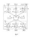
種々の実施形態は、血管拡張および血管収縮を含む、心拍数および血圧に対してANSが及ぼす作用に言及する。心拍および力は、交感神経系が刺激されると増加させられ、交感神経系が抑制される(副交感神経系が刺激される)と減少させられる。図1Aおよび1Bは、末梢血管制御のための神経機構を図示する。図1Aは概して、血管運動神経中枢への求心性神経を図示する。求心性神経は、神経中枢に向かってインパルスを伝える。血管運動神経中枢は、血管を拡張および収縮して血管のサイズを制御する神経に関する。図1Bは概して、血管運動神経中枢からの遠心性神経を図示する。遠心性神経は、神経中枢から離れる方向にインパルスを伝える。 Various embodiments refer to the effects of ANS on heart rate and blood pressure, including vasodilation and vasoconstriction. Heart rate and power are increased when the sympathetic nervous system is stimulated and decreased when the sympathetic nervous system is suppressed (the parasympathetic nervous system is stimulated). 1A and 1B illustrate neural mechanisms for peripheral vascular control. FIG. 1A generally illustrates afferent nerves to the vasomotor center. Afferent nerves carry impulses towards the nerve center. The vasomotor center relates to nerves that dilate and contract blood vessels to control the size of the blood vessels. FIG. 1B generally illustrates efferent nerves from a vasomotor center. Efferent nerves carry impulses away from the nerve center.
交感神経系および副交感神経系を刺激すると、心拍数および血圧以外の作用を及ぼすことができる。例えば、交感神経系を刺激すると、瞳孔を拡張し、唾液および粘液の産生を低減し、気管支筋を弛緩し、胃の不随意収縮(蠕動)の連続波および胃の運動性を低減し、肝臓によるグリコーゲンのグルコースへの変換を増加し、腎臓による尿分泌を減少し、膀胱の壁を弛緩して括約筋を閉じる。副交感神経系を刺激する(交感神経系を抑制する)と、瞳孔を収縮し、唾液および粘液の産生を増加し、気管支筋を収縮し、胃および大腸における分泌物および運動性を増加し、小腸における消化を増加し、尿分泌を増加し、膀胱の壁を収縮して括約筋を弛緩する。交感神経系および副交感神経系と関連する機能は多く、互いに複雑に統合することができる。したがって、1つの生理系で血管拡張等の所望の反応を達成する、交感神経系および/副交感神経系の無差別刺激はまた、他の生理系で望ましくない反応をもたらす場合がある。 Stimulation of the sympathetic and parasympathetic nervous systems can have effects other than heart rate and blood pressure. For example, stimulating the sympathetic nervous system dilates the pupil, reduces saliva and mucus production, relaxes bronchial muscles, reduces the continuous wave of involuntary contraction of the stomach (peristalsis), and reduces gastric motility, Increases the conversion of glycogen to glucose by the kidneys, decreases urinary secretion by the kidneys, relaxes the bladder wall and closes the sphincter. Stimulating the parasympathetic nervous system (suppressing the sympathetic nervous system) contracts the pupil, increases saliva and mucus production, contracts bronchial muscles, increases secretion and motility in the stomach and large intestine, Increases digestion, increases urinary secretion, contracts the bladder wall and relaxes the sphincter. The functions associated with the sympathetic and parasympathetic nervous systems are many and can be complexly integrated with each other. Thus, promiscuous stimulation of the sympathetic and / or parasympathetic nervous system that achieves a desired response, such as vasodilation, in one physiological system may also lead to undesirable responses in other physiological systems.
圧反射は、圧受容器の刺激によって誘起される反射である。圧受容器は、心耳、心臓脂肪体、大静脈、大動脈弓、および頸動脈洞の壁の中の感覚神経終末等の、圧力変化の任意の感覚器を含み、それは、内側からの圧力上昇に起因する壁の伸張に敏感であり、その圧力を低減する傾向がある中枢性反射機構の受容器官として機能する。加えて、圧反射経路は、感覚神経終末から通じる、迷走神経、大動脈神経、および頸動脈神経等の求心性神経幹を含む。圧反射刺激は、交感神経活動を抑制し(副交感神経系を刺激する)、末梢血管抵抗および心筋収縮能を減少させることによって全身動脈圧を減少させる。圧受容器は、動脈壁の内圧および伸張によって自然に刺激される。 Baroreflex is a reflex induced by baroreceptor stimulation. Baroreceptors include any sensory organs of pressure change, such as the atrial appendage, cardiac fat pad, vena cava, aortic arch, and sensory nerve endings in the carotid sinus wall, due to increased pressure from the inside It acts as a receptive organ of the central reflex mechanism that is sensitive to wall stretching and tends to reduce its pressure. In addition, the baroreflex pathway includes afferent nerve trunks such as the vagus, aortic, and carotid nerves that lead from sensory nerve endings. Baroreflex stimulation reduces systemic arterial pressure by suppressing sympathetic nerve activity (stimulating the parasympathetic nervous system) and decreasing peripheral vascular resistance and myocardial contractility. Baroreceptors are naturally stimulated by internal pressure and stretching of the arterial wall.
本主題の一部の側面は、神経系を無差別に刺激することの望ましくない作用を低減しながら、所望の反応(例えば、高血圧症の低減)を刺激する目的で、求心性神経幹を刺激するよりもむしろ、動脈壁の中の特定神経終末を局所的に刺激する。例えば、一部の実施形態においては、肺動脈中の圧受容器部位を刺激する。本主題の一部の実施形態は、大動脈、心腔、および心臓の脂肪体の中の圧受容器部位または神経終末のいずれかを刺激するステップを伴い、本主題の一部の実施形態は、迷走神経、頸動脈神経、および大動脈神経等の求心性神経幹を刺激するステップを伴う。一部の実施形態は、カフ電極を使用して求心性神経幹を刺激し、一部の実施形態は、神経に最も近い血管中に配置される血管内リードを使用して求心性神経幹を刺激するために、電気刺激が血管壁を通過して求心性神経幹を刺激する。 Some aspects of the present subject matter stimulate afferent nerve trunks for the purpose of stimulating a desired response (eg, reducing hypertension) while reducing the undesirable effects of stimulating the nervous system indiscriminately Rather, it stimulates specific nerve endings in the arterial wall locally. For example, in some embodiments, a baroreceptor site in the pulmonary artery is stimulated. Some embodiments of the present subject matter involve stimulating either baroreceptor sites or nerve endings in the aorta, heart chambers, and cardiac fat pads, and some embodiments of the present subject matter are vagus With stimulating afferent nerve trunks such as nerves, carotid nerves, and aortic nerves. Some embodiments use cuff electrodes to stimulate afferent nerve trunks, and some embodiments use vascular leads placed in blood vessels closest to the nerve to afferent nerve trunks. To stimulate, an electrical stimulus passes through the vessel wall and stimulates the afferent nerve trunk.
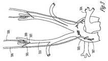
図2A−2Cは、心臓を図示する。図2Aに図示されるように、心臓201は、上大静脈202、大動脈弓203、および肺動脈204を含み、図3−5の図解との文脈上の関係を提供することに有用である。下記でさらに詳細に論じられるように、肺動脈204は、圧受容器を含む。リードは、心臓ペースメーカーリードと同様に、末梢静脈を通り、三尖弁を通り、心臓の右心室の中へと(図中で明示せず)、血管内に挿入されて、右心室から肺動脈弁を通って肺動脈の中へ進み続けることが可能である。肺動脈および大動脈の一部は、互いに近接している。種々の実施形態は、肺動脈に血管内で配置されるリードを使用して、大動脈中の圧受容器を刺激する。したがって、本主題の種々の側面によれば、圧反射は、肺動脈の中へ血管内に挿入される少なくとも1つの電極によって、肺動脈の中または周囲において刺激される。あるいは、圧力感知性能があるか、またはない、無線刺激機器が、カテーテルを介して肺動脈の中に配置されてもよい。刺激および/または刺激のためのエネルギーの制御は、超音波、電磁、またはそれらの組み合わせを介して、別の埋込型または外部機器によって供給されてもよい。本主題の側面は、圧反射刺激装置を肺動脈の中の血管内に埋め込む、比較的非侵襲性の外科技術を提供する。 2A-2C illustrate the heart. As illustrated in FIG. 2A, the
図2B−2Cは、それぞれ心臓の右側および左側を図示し、圧受容器部位として機能する神経終末を有する心臓脂肪体をさらに図示する。図2Bは、右心房267、右心室268、洞房結節269、上大静脈202、下大静脈270、大動脈271、右肺静脈272、右肺動脈273を図示する。図2Bはまた、上大静脈と大動脈との間の心臓脂肪体274も図示する。心臓脂肪体274中の圧受容器神経終末は、一部の実施形態では、脂肪体にねじ込まれる電極を使用して刺激され、一部の実施形態では、例えば、右肺動脈または上大静脈等の血管中の脂肪体に近接して配置される血管内供給リードを使用して刺激される。図2Cは、左心房275、左心室276、右心房267、右心室268、上大静脈202、下大静脈270、大動脈271、右肺静脈272、左肺静脈277、右肺動脈273、および冠状静脈洞278を図示する。図2Cはまた、右心静脈の最も近くに位置する心臓脂肪体279、ならびに下大静脈および左心房の最も近くに位置する心臓脂肪体280も図示する。脂肪体279中の圧受容器神経終末は、一部の実施形態では、脂肪体279にねじ込まれる電極を使用して刺激され、一部の実施形態では、例えば、右肺動脈273または右肺静脈272等の血管中の脂肪体に近接して配置される血管内供給リードを使用して刺激される。脂肪体280中の圧受容器は、一部の実施形態では、脂肪体にねじ込まれる電極を使用して刺激され、一部の実施形態では、例えば、下大静脈270または冠状静脈洞等の血管中の脂肪体に近接して配置される血管内供給リード、または左心房275中のリードを使用して刺激される。 2B-2C illustrate the right and left sides of the heart, respectively, further illustrating a cardiac fat pad with nerve endings that function as baroreceptor sites. FIG. 2B illustrates
図3は、頸動脈洞305、大動脈弓303、および肺動脈304の領域中の圧受容器を図示する。大動脈弓303および肺動脈304は、図2Aに関して以前に図示した。図3に図示されるように、迷走神経306は、大動脈弓303中、頸動脈洞305中、および総頸動脈310中の圧受容器として機能する、感覚神経終末307を延在し、提供する。舌咽神経308は、頸動脈洞305中の圧受容器として機能する神経終末309を提供する。これらの神経終末307および309は、例えば、内部からの圧力上昇に起因する壁の伸張に敏感である。これらの神経終末の活性化は、圧力を低減する。図中に図示されていないものの、心臓の脂肪体ならびに心房および心室も、圧受容器を含む。カフは、迷走神経等の求心性神経幹の周囲に配置されており、圧受容器から血管運動神経中枢に通って、圧反射を刺激する。本主題の種々の実施形態によれば、求心性神経に最も近い血管中に配置されるカフまたは血管内供給リードを使用して、求心性神経幹を刺激することができる。 FIG. 3 illustrates baroreceptors in the areas of the
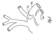
図4は、肺動脈404の中および周囲の圧受容器を図示する。上大静脈402および大動脈弓403も図示される。図示されるように、肺動脈404は、色の濃い領域によって概して示されるような、多数の圧受容器411を含む。その上、一群の密集した圧受容器が、動脈管索412の付着部の近傍に位置している。図4はまた、心臓の右心室413、および肺動脈404から右心室413を分離する肺動脈弁414も図示する。本主題の種々の実施形態によれば、リードが、末梢静脈を通して挿入され、三尖弁を通って右心室の中へ、そして右心室413から肺動脈弁414を通って肺動脈404の中へ通されて、肺動脈の中および/または周囲の圧受容器を刺激する。種々の実施形態では、例えば、リードは、動脈管索412の近傍の一群の圧受容器を刺激するように配置される。図5は、動脈管索および肺動脈幹504近傍の、大動脈弓503中の圧受容器域512を図示する。一部の実施形態は、肺動脈にリードを配置して、大動脈および/または2B−2Cに図示されるような脂肪体中の圧受容器部位を刺激する。 FIG. 4 illustrates baroreceptors in and around the
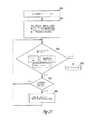
図6は、左大動脈神経が刺激された時の呼吸615と血圧616の既知の関係を図示する。617において神経が刺激されると、血圧616は低下し、呼吸615は、呼吸波形のより高い周波数および振幅によって図示されるように、より速く、かつより深くなる。呼吸および血圧は、刺激が除去された後、約1〜2分後に刺激前の状態に戻るように思われる。本主題の種々の実施形態は、血圧に対する代理パラメータとして呼吸を使用することによって、この呼吸と血圧の関係を使用する。 FIG. 6 illustrates the known relationship between
図7は、断続的な頸動脈神経刺激の6ヶ月間の高血圧症イヌにおける、頸動脈神経刺激に対する既知の血圧反応を図示する。図は、刺激したイヌ718の血圧が、同様に高血圧を有する対照イヌ719の血圧よりも有意に低いことを図示する。したがって、断続的刺激は、圧反射を誘起して高血圧を低減することが可能である。 FIG. 7 illustrates the known blood pressure response to carotid nerve stimulation in a hypertensive dog during 6 months of intermittent carotid nerve stimulation. The figure illustrates that the blood pressure of the stimulated
心不全とは、心臓機能が、末梢組織の代謝要求を満たすのに十分なレベルを下回り得る正常以下の心拍出量を引き起こす、臨床的症候群を指す。心不全は、付随する静脈および肺のうっ血によるうっ血性心不全(CHF)として現れる場合がある。心不全は、虚血性心疾患等の種々の病因によるものとなり得る。 Heart failure refers to a clinical syndrome in which cardiac function causes subnormal cardiac output that can be below levels sufficient to meet the metabolic demands of peripheral tissues. Heart failure may manifest as congestive heart failure (CHF) due to accompanying venous and pulmonary congestion. Heart failure can be due to a variety of etiologies such as ischemic heart disease.
心不全患者には、LV機能障害および死亡率の増加と関連する自律平衡の低減がある。交感神経系および副交感神経系の変調には、心不全およびMI後患者における再造形および死亡を防ぐ潜在的な臨床的有益性がある。直接電気刺激は、圧反射を活性化することができ、交感神経活動の低減を誘発し、血管抵抗を減少させることによって血圧を低減する。交感神経抑制および副交感神経活性は、おそらく急性虚血心筋の側副かん流を増加させ、心筋障害を減少させることによって、心筋梗塞後の不整脈脆弱性の低減と関連している。 Heart failure patients have reduced autonomic balance associated with increased LV dysfunction and increased mortality. Sympathetic and parasympathetic modulation has potential clinical benefits to prevent remodeling and death in patients with heart failure and post-MI. Direct electrical stimulation can activate the baroreflex, induces a reduction in sympathetic activity and reduces blood pressure by reducing vascular resistance. Sympathetic inhibition and parasympathetic activity are associated with reduced arrhythmia vulnerability after myocardial infarction, possibly by increasing collateral perfusion of acute ischemic myocardium and reducing myocardial damage.
心筋梗塞(MI)または心拍出量の減少の他の原因の後に、構造、生化学、神経ホルモン、および電気生理学的因子を伴う、心室の複雑な再造形過程が発生する。心室再造形は、心室の拡張期充満圧を増加させる、いわゆる後方不全により、心拍出量を増加させるように作用する、生理学的代償機構によって誘起され、それにより、いわゆる前負荷(すなわち、心臓拡張期の終わりに、心室中の血液の量によって心室が伸張される程度)を増加させる。前負荷の増加は、フランク−スターリングの原則として知られる現象である、心臓収縮期中の1回拍出量の増加を引き起こす。しかしながら、ある期間にわたって前負荷の増加により心室が伸張されると、心室は拡張する。心室容積の拡大は、所与の収縮期圧における心室壁応力の増加を引き起こす。心室によって行われる圧力−体積作業の増加とともに、このことは心室筋の肥大に対する刺激の役割を果たす。拡張の不利点は、正常な残存心筋に課せられる余分な作業負荷、および肥大に対する刺激を表す壁張力の増加(ラプラスの法則)である。肥大が増加した張力に適合するのに十分ではない場合、さらなる進行性拡張を引き起こす悪循環が後に続いて起こる。 Following myocardial infarction (MI) or other causes of decreased cardiac output, a complex remodeling process of the ventricle occurs with structure, biochemistry, neurohormones, and electrophysiological factors. Ventricular remodeling is triggered by a physiological compensatory mechanism that acts to increase cardiac output by so-called posterior failure, which increases ventricular diastolic filling pressure, and thereby the so-called preload (ie, the heart At the end of the diastole, the extent to which the ventricle is stretched by the amount of blood in the ventricle) Increased preload causes an increase in stroke volume during systole, a phenomenon known as the Frank-Sterling principle. However, when the ventricle is stretched due to increased preload over a period of time, the ventricle expands. Expansion of the ventricular volume causes an increase in ventricular wall stress at a given systolic pressure. With increasing pressure-volume work performed by the ventricles, this serves as a stimulus for ventricular muscle hypertrophy. Disadvantages of dilation are the extra workload imposed on normal residual myocardium and an increase in wall tension (Laplace's law) that represents a stimulus for hypertrophy. If the hypertrophy is not sufficient to accommodate the increased tension, a vicious cycle follows that causes further progressive dilatation.
心臓が拡張し始めるにつれて、ホルモン分泌および交感神経放電に反応する、血管運動中枢神経系の制御中枢に、求心性圧受容器および心肺受容器信号が送信される。最終的に、心室再造形に関与する細胞構造の有害な変化の主な原因となるのは、血行動態的な交感神経系およびホルモンの変調の組み合わせ(アンギオテンシン変換酵素(ACE)活性の有無等)である。肥大を引き起こす持続的応力は、心筋細胞のアポトーシス(すなわち、プログラム細胞死)、および心臓機能のさらなる低下を引き起こす最終的な壁の菲薄化を誘発する。したがって、心室拡張および肥大は、最初は代償性であり、かつ心拍出量を増加させる場合があるものの、この過程は、最終的には収縮および拡張(代償不全)両方の機能障害をもたらす。心室再造形の程度は、MI後および心不全患者における死亡率の増加と正の相関があることが示されている。 As the heart begins to dilate, afferent baroreceptor and cardiopulmonary receptor signals are sent to the control center of the vasomotor central nervous system in response to hormone secretion and sympathetic discharge. Ultimately, the major cause of the detrimental changes in cell structure involved in ventricular remodeling is a combination of hemodynamic sympathetic nervous system and hormonal modulation (eg presence or absence of angiotensin converting enzyme (ACE) activity) It is. Sustained stress that causes hypertrophy induces apoptosis of cardiomyocytes (ie, programmed cell death) and eventual wall thinning that causes further decline in cardiac function. Thus, although ventricular dilatation and hypertrophy are initially compensatory and may increase cardiac output, this process ultimately results in both contraction and dilation (compensation failure) dysfunction. The degree of ventricular remodeling has been shown to be positively correlated with increased mortality in post-MI and heart failure patients.
(刺激システム)
本主題の種々の実施形態は、神経刺激(NS)(例えば、圧反射刺激)機器または部品に関する。神経性刺激は、神経連絡を刺激する、または神経連絡を抑制するために使用することができる。神経連絡を刺激する神経性刺激の一実施例は、低周波数信号(例えば、約20Hzから50Hzまでの範囲内)である。神経連絡を抑制する神経性刺激の一実施例は、高周波数信号(例えば、約120Hzから150Hzまでの範囲内)である。所定の場所に配置される刺激電極を使用して、所望の神経標的に電気刺激パルスを印加する他の実施形態を含む、神経連絡を刺激および抑制するための他の方法が提案されている。加えて、神経を刺激する際に使用するために、超音波、光、または磁気エネルギー等の他のエネルギーの種類が提案されている。本主題の種々の実施形態によれば、交感神経標的は、腓骨神経、脊髄中の交感神経柱、および心臓節後交感神経ニューロンを含むが、それらに限定されない。本主題の種々の実施形態によれば、副交感神経神経標的は、迷走神経、圧受容器、および心臓脂肪体を含むが、それらに限定されない。(Stimulation system)
Various embodiments of the present subject matter relate to neural stimulation (NS) (eg, baroreflex stimulation) devices or components. Neural stimulation can be used to stimulate neural communication or suppress neural communication. One example of neural stimulation that stimulates neural communication is a low frequency signal (eg, in the range of about 20 Hz to 50 Hz). One example of a neural stimulus that suppresses nerve traffic is a high frequency signal (eg, in the range of about 120 Hz to 150 Hz). Other methods have been proposed for stimulating and suppressing neural communication, including other embodiments that use stimulation electrodes placed in place to apply electrical stimulation pulses to a desired neural target. In addition, other energy types such as ultrasound, light, or magnetic energy have been proposed for use in stimulating nerves. According to various embodiments of the present subject matter, sympathetic targets include, but are not limited to, radial nerves, sympathetic nerve columns in the spinal cord, and postcardiac sympathetic neurons. According to various embodiments of the present subject matter, parasympathetic nerve targets include, but are not limited to, the vagus nerve, baroreceptor, and cardiac fat pad.
神経刺激装置の実施例は、高血圧症を治療するために使用される血圧降下(AHT)機器またはAHT部品、抗再造形療法を提供する神経刺激装置、および同等物を含む。本主題の種々の実施形態は、独立型の埋込型圧受容器刺激システムを含み、NSおよび心調律管理(CRM)部品を統合した埋込型機器を含み、少なくとも1つの埋込型NS機器と、無線で、または埋込型機器を接続するワイヤリードを介してのいずれかで、互いに通信することが可能な埋込型CRM機器とを伴うシステムを含む。同じ機器または別個の機器のいずれかで行われるNSおよびCRM機能を統合すると、NS療法および心臓療法が共に知的に(intelligently)機能することを可能にすることによって、これらの治療法の側面を改善する。 Examples of neurostimulators include blood pressure lowering (AHT) devices or AHT components used to treat hypertension, neurostimulators that provide anti-remodeling therapy, and the like. Various embodiments of the present subject matter include a stand-alone implantable baroreceptor stimulation system, include an implantable device that integrates NS and cardiac rhythm management (CRM) components, and includes at least one implantable NS device and Including systems with implantable CRM devices that can communicate with each other, either wirelessly or via wire leads connecting the implantable devices. The integration of NS and CRM functions performed either on the same device or on separate devices will enable these therapeutic aspects by enabling both NS therapy and cardiac therapy to function intelligently. Improve.
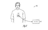
図8は、本主題の種々の実施形態による、埋込型医療機器(IMD)821およびプログラマ822を含むシステム820を図示する。IMD821の種々の実施形態は、神経刺激装置機能のみを含み、種々の実施形態は、NS機能およびCRM機能の組み合わせを含む。神経刺激装置の一部の実施形態は、AHT機能を提供する。プログラマ822およびIMD821は、データおよび命令を無線で伝達することが可能である。種々の実施形態では、例えば、プログラマ822およびIMD821は、データおよび命令を無線で伝達するためにテレメトリコイルを使用する。したがって、IMD821によって提供されるプログラムした治療を調整するためにプログラマを使用することができ、IMDは、例えば、無線テレメトリを使用して、機器データ(バッテリおよびリード抵抗等)および治療データ(感知および刺激データ等)をプログラマに報告することができる。種々の実施形態によれば、IMD821は、圧受容器を刺激してAHT療法等のNS療法を提供する。IMD821の種々の実施形態は、心臓ペースメーカーリードと同様に右心室を通して供給され、さらに肺動脈の中へ供給されるリードを使用して、肺動脈中の圧受容器を刺激する。種々の実施形態によれば、IMD821は、ANS活動を感知するセンサを含む。閉ループ制御システムでフィードバックを行うために、そのようなセンサを使用することができる。例えば、種々の実施形態は、ANS活動を示す、呼吸および血圧等の代理パラメータを感知する。種々の実施形態は、心拍数、分時換気量、動作センサ、および同等物等の活動センサを含む。種々の実施形態によれば、IMDは、圧受容器を刺激する、および/またはANS活動を感知する性能に加えて、ペーシングおよび除細動等の心臓刺激性能をさらに含む。 FIG. 8 illustrates a
図9は、本主題の種々の実施形態による、図8のシステム820において示されるIMD821等の埋込型医療機器(IMD)921を図示する。図示したIMD921は、NS機能を果たす。図示したIMD921の一部の実施形態は、AHT機能を果たすため、埋込型AHT機器を図示する。図示した機器921は、制御器回路923およびメモリ924を含む。制御器回路923は、ハードウェア、ソフトウェア、ならびにハードウェアおよびソフトウェアの組み合わせを使用して実装されることが可能である。例えば、種々の実施形態によれば、制御器回路923は、メモリ924に埋め込まれた命令を実行して、AHT療法等のNS療法と関連する機能を果たすための、プロセッサを含む。例えば、図示した機器921は、プログラマあるいは別の外部または内部機器と通信するための使用に対する、トランシーバ925および関連回路をさらに含む。種々の実施形態は、無線通信性能を有する。例えば、一部のトランシーバの実施形態は、プログラマあるいは別の外部または内部機器と無線通信するために、テレメトリコイルを使用する。 FIG. 9 illustrates an implantable medical device (IMD) 921 such as the
図示した機器921は、神経刺激装置回路926をさらに含む。機器921の種々の実施形態はまた、センサ回路927も含む。1つ以上のリードは、センサ回路927および刺激装置回路926に接続されることが可能である。神経刺激装置回路926は、1つ以上の刺激電極を通して、所望の神経標的(例えば、圧反射部位または他の神経標的)に電気刺激パルスを印加するために使用される。センサ回路927は、ANS神経活動および/または血圧、呼吸、および同等物等の代理パラメータを検出および処理して、ANS活動を判定するために使用される。 The illustrated
種々の実施形態によれば、刺激装置回路926は、刺激パルスの振幅928、刺激パルスの周波数929、パルスのバースト周波数930または負荷サイクル、およびパルスの波の形態931といったパルスの特徴のうちのいずれか1つ、または2つ以上の任意の組み合わせを設定するモジュールを含む。波の形態の例は、方形波、三角波、正弦波、および自然発生の圧反射刺激を示すような白色雑音を模倣する所望の調和成分を伴う波を含む。 According to various embodiments, the
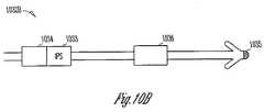
図10A−10Cは、本主題の種々の実施形態による、統合圧力センサ(IPS)を伴う圧受容器刺激リードを図示する。一定の縮尺で描かれていないものの、これらの図示したリード1032A、1032B、および1032Cは、圧受容器刺激装置電極1034を伴うIPS1033を含んで、血圧の変化、および圧受容器刺激の作用を監視する。これらのリードの実例は、本主題の他の側面および実施形態を制限するものとして解釈すべきではない。例えば、種々の実施形態では、血圧を感知するために、微小電子機械システム(MEMS)技術が使用される。一部のセンサ実施形態は、膜の変位に基づいて血圧を判定する。 10A-10C illustrate baroreceptor stimulation leads with integrated pressure sensors (IPS), according to various embodiments of the present subject matter. Although not drawn to scale, these illustrated leads 1032A, 1032B, and 1032C include
図10A−10Cは、リード上のIPSを図示する。一部の実施形態は、IMDまたはNS機器にIPSを埋め込む。たとえ刺激装置およびセンサが別個のリードまたは場所に位置していても、刺激装置およびセンサ機能を統合することができる。 10A-10C illustrate IPS on a lead. Some embodiments embed IPS in IMD or NS devices. The stimulator and sensor functions can be integrated even if the stimulator and sensor are located on separate leads or locations.
図10Aに図示されるリード1032Aは、遠位に配置した圧受容器刺激装置電極1034およびIPS1033を含む。このリードは、例えば、肺動脈、大動脈弓、動脈管索、冠状静脈洞、心房および心室、および/または心臓脂肪体中の圧受容器部位等の圧受容器部位を刺激するように、血管内導入されることが可能である。 The
図10Bに図示されるリード1032Bは、先端電極1035、第1のリング電極1036、第2のリング電極1034、およびIPS1033を含む。このリードは、心腔の中に、またはその最も近くに血管内挿入され、さらに、電極1035、1036、および1034のうちの少なくともいくつかが、心臓のペースを合わせる、あるいは心臓を刺激するために使用されることが可能であり、かつ電極のうちの少なくともいくつかが、少なくとも1つの圧受容器部位を刺激することが可能であるように、圧受容器部位の最も近くに配置されてもよい。IPS1033は、血圧を感知するために使用される。種々の実施形態では、IPSは、刺激のために選択された圧受容器部位に最も近い血管における血圧を感知するために使用される。 The
図10Cに図示されるリード1032Cは、遠位に配置した圧受容器刺激装置電極1034、IPS1033、およびリング電極1036を含む。このリード1032Cは、例えば、右心房および右心室の中へ、次いで肺動脈弁を通って肺動脈の中へ血管内挿入されてもよい。機器のプログラミングによっては、電極1036は、右心室内で発生してもよい活動等の心臓活動のペースを合わせる、および/または感知するために使用することができ、電極1034およびIPS1033は、肺動脈の中または周囲の圧受容器の近傍に位置して、直接的にまたは代理パラメータを通して間接的に、のいずれかで、圧反射活動を刺激および感知する。 The lead 1032C illustrated in FIG. 10C includes a
したがって、本主題の種々の実施形態は、IPSを使用して圧受容器刺激を自動的に変調する、埋込型NS機器を提供する。圧力センサをリードに統合することは、刺激に対する局所化されたフィードバックを提供する。この局所的な感知は、フィードバック制御を改善する。例えば、統合センサは、標的が連続してオーバーシュートされないように、圧反射の慣性を補うために使用することができる。種々の実施形態によれば、機器は、平均動脈圧、収縮期圧、拡張期圧、および同等物等の圧力パラメータを監視する。例えば、平均動脈圧が増加するか、またはプログラム可能な標的圧力を上回ったままであると、機器は、増加した割合で圧受容器を刺激し、血圧を低減して高血圧症を制御する。平均動脈圧が標的圧力に向かって減少するにつれて、機器は、圧受容器刺激を低減することによって反応する。種々の実施形態では、アルゴリズムが現在の代謝状態(心臓要求)を考慮に入れ、それにしたがって神経性刺激を調整する。IPSを有するNS機器は、圧受容器刺激を自動的に変調することができ、それは、埋込型NS機器が患者の高血圧症のレベルを判定し、適切なレベルの治療を送達することによって反応することを可能にする。しかしながら、閉ループフィードバック制御を提供するために、NSまたは神経刺激機器に存在しないセンサを含む、他のセンサを使用できることに留意する。 Accordingly, various embodiments of the present subject matter provide an implantable NS device that automatically modulates baroreceptor stimulation using IPS. Integrating the pressure sensor into the lead provides localized feedback for the stimulus. This local sensing improves feedback control. For example, an integrated sensor can be used to compensate for baroreflex inertia so that the target is not continuously overshooted. According to various embodiments, the device monitors pressure parameters such as mean arterial pressure, systolic pressure, diastolic pressure, and the like. For example, if the mean arterial pressure increases or remains above a programmable target pressure, the device stimulates baroreceptors at an increased rate, reducing blood pressure and controlling hypertension. As the mean arterial pressure decreases toward the target pressure, the device responds by reducing baroreceptor stimulation. In various embodiments, the algorithm takes into account the current metabolic state (cardiac demand) and adjusts the neural stimulation accordingly. NS devices with IPS can automatically modulate baroreceptor stimulation, which responds by the implantable NS device determining the patient's level of hypertension and delivering the appropriate level of therapy. Make it possible. However, it should be noted that other sensors can be used to provide closed loop feedback control, including sensors that are not present in NS or neurostimulator devices.
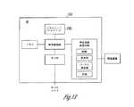
図11は、本主題の種々の実施形態による、神経刺激(NS)部品1137および心調律管理(CRM)部品1138を有する、図8の821においてに示されるような埋込型医療機器(IMD)1121を図示する。図示した機器1121は、制御器1123およびメモリ1124を含む。種々の実施形態によれば、制御器1123は、ハードウェア、ソフトウェア、またはハードウェアとソフトウェアとの組み合わせを含んで、圧受容器刺激およびCRMの機能を果たす。例えば、本開示で論じられる、プログラムした治療の適用は、メモリに埋め込まれるコンピュータ可読命令として格納され、プロセッサによって実行されることが可能である。種々の実施形態によれば、制御器1123は、プロセッサを含んで、メモリに埋め込まれた命令を実行し、圧受容器刺激およびCRMの機能を果たす。図示した機器1121は、プログラマあるいは別の外部または内部機器と通信するための使用に対する、トランシーバ1125および関連回路をさらに含む。種々の実施形態は、テレメトリコイルを含む。 FIG. 11 illustrates an implantable medical device (IMD) as shown at 821 in FIG. 8 having a neural stimulation (NS)
CRM療法部分1138は、制御器の制御下にある部品を含んで、心臓を刺激し、および/または1つ以上の電極を使用して心臓信号を感知する。CRM療法部分は、電極を通して電気信号を提供して心臓を刺激するための使用に対する、パルス発生器1139を含み、さらに、感知回路1140を含んで、感知された心臓信号を検出および処理する。インターフェース1141は概して、制御器1123とパルス発生器1139および感知回路1140との間で通信するための使用に対して図示されている。3つの電極が、CRM療法を提供するための使用の一実施例として図示されている。しかしながら、本主題は、特定数の電極部位に限定されない。各電極は、独自のパルス発生器および感知回路を含んでもよい。しかしながら、本主題はそのように限定されない。複数の電極を用いて機能するように、信号パルス発生および感知機能を多重化することができる。 The
NS療法部分1137は、制御器の制御下にある部品を含んで、圧受容器を刺激し、および/または、神経活動と関連するANSパラメータ、または血圧および呼吸等のANSパラメータの代理を感知する。3つのインターフェース1142が、ANS療法を提供するための使用に対して図示されている。しかしながら、本主題は、特定数のインターフェースに、あるいは任意の特定刺激または感知機能に限定されない。パルス発生器1143は、圧受容器部位を刺激するための使用に対して、電極に電気パルスを提供するために使用される。種々の実施形態によれば、パルス発生器は、刺激パルスの振幅、刺激パルスの周波数、パルスのバースト周波数、および、方形波、三角波、正弦波、ならびに白色雑音または他の信号を模倣する所望の調和成分を伴う波等のパルスの形態を設定し、かつ一部の実施形態では変更する、回路を含む。感知回路1144は、神経活動、血圧、呼吸、および同等物のセンサ等のセンサから、信号を検出および処理するために使用される。インターフェース1142は概して、制御器1123とパルス発生器1143および感知回路1144との間で通信するための使用に対して図示されている。各インターフェースは、例えば、別個のリードを制御するために使用してもよい。NS療法部分の種々の実施形態は、パルス発生器のみを含み、圧受容器を刺激する。例えば、NS療法部分は、AHT療法を提供する。
本主題のある側面は、定常的に埋め込んだ刺激システムに関し、この刺激システムは、血圧を監視し、かつ圧受容器を刺激して圧受容器反射を活性化し、血管運動神経中枢からの交感神経放電を抑制することによって、高血圧症を治療するように特別に設計されている。圧受容器は、頸動脈洞および大動脈弓等の種々の解剖学的場所に位置する。他の圧受容器の場所は、動脈管索を含む肺動脈、ならびに心房および心室内の部位を含む。種々の実施形態では、システムは、ペースメーカー/除細動器または他の電気刺激システムに統合される。システムの部品は、高周波数パルス発生器、血圧または他の関連する生理学的パラメータを監視するセンサ、圧受容器に電気刺激を印加するリード、刺激を付与するのに適切な時間を判定するアルゴリズム、ならびに表示および患者管理のためのデータを操作するアルゴリズムを含む。 One aspect of the present subject matter relates to a regularly implanted stimulation system that monitors blood pressure and stimulates the baroreceptor to activate baroreceptor reflexes, thereby producing a sympathetic discharge from the vasomotor center. Specially designed to treat hypertension by inhibiting. Baroreceptors are located in various anatomical locations such as the carotid sinus and the aortic arch. Other baroreceptor locations include pulmonary arteries, including arterial chords, and sites within the atria and ventricles. In various embodiments, the system is integrated into a pacemaker / defibrillator or other electrical stimulation system. The components of the system include a high frequency pulse generator, a sensor that monitors blood pressure or other relevant physiological parameters, a lead that applies electrical stimulation to the baroreceptor, an algorithm that determines the appropriate time to apply the stimulation, and Includes algorithms for manipulating data for display and patient management.
種々の実施形態は、患者にAHT療法等の電気的に媒介されるNS療法を送達しようとするシステムに関する。種々の実施形態は、「独立型」パルス発生器を、肺動脈の中等の心臓付近の圧受容器を直接刺激する、低侵襲性の単極リードと組み合わせる。この実施形態は、専門医の技能を欠く一般診療医がそれを埋め込むことができるようなものである。種々の実施形態は、血圧を示すパラメータを感知することができる、単純な埋め込みシステムを組み込む。このシステムは、所望の生活の質を維持するように、治療出力(波形の振幅、周波数等)を調整する。種々の実施形態では、埋め込みシステムは、パルス発生機器およびリードシステムを含み、その刺激電極は、経静脈埋込技術を使用して、心内膜圧受容器組織の近傍に配置される。別の実施形態は、NS療法を従来の徐脈性不整脈、頻脈性不整脈、および/またはうっ血性心不全(CHF)療法と組み合わせるシステムを含む。一部の実施形態は、機器ヘッダから出現し、改良された従来のパルス発生システムから離間する、追加の「圧受容器リード」を使用する。別の実施形態では、従来のCRMリードは、圧受容器部位の近傍に自然に配置される、近位電極を組み込むように修正される。これらのリードにより、遠位電極はCRM療法を提供し、近位電極は圧受容器を刺激する。 Various embodiments relate to systems that attempt to deliver an electrically mediated NS therapy, such as AHT therapy, to a patient. Various embodiments combine a “stand alone” pulse generator with a minimally invasive monopolar lead that directly stimulates baroreceptors near the heart, such as in the pulmonary artery. This embodiment is such that a general practitioner lacking the skills of a specialist can be implanted. Various embodiments incorporate a simple implantation system that can sense a parameter indicative of blood pressure. This system adjusts the therapeutic output (waveform amplitude, frequency, etc.) to maintain the desired quality of life. In various embodiments, the implantation system includes a pulse generating device and a lead system, and the stimulation electrode is placed in proximity to the endocardial baroreceptor tissue using a transvenous implantation technique. Another embodiment includes a system that combines NS therapy with conventional bradyarrhythmia, tachyarrhythmia, and / or congestive heart failure (CHF) therapy. Some embodiments use an additional “baroreceptor lead” that emerges from the instrument header and is spaced from the improved conventional pulse generation system. In another embodiment, a conventional CRM lead is modified to incorporate a proximal electrode that is naturally positioned near the baroreceptor site. With these leads, the distal electrode provides CRM therapy and the proximal electrode stimulates the baroreceptor.
これらの実施形態によるシステムは、部分的に成功した治療戦略を増強させるために使用することができる。一実施例として、望ましくない副作用は、一部の医薬品の使用を制限する場合がある。薬剤投与量の低減とのこれらの実施形態によるシステムの組み合わせは、特に有益であってもよい。 Systems according to these embodiments can be used to augment partially successful treatment strategies. As an example, undesirable side effects may limit the use of some pharmaceuticals. The combination of systems according to these embodiments with drug dose reduction may be particularly beneficial.
種々の実施形態によれば、リードおよびリード上の電極は、電極がパルスを適切に伝送し、かつ、心臓から信号を感知することを可能にする態様で心臓に対して、および圧反射を刺激するように圧受容器に対して、物理的に配設される。多数のリード、および1つのリードにつき多数の電極があってもよいため、1つまたは複数の特定電極を使用するように構成をプログラムすることができる。種々の実施形態によれば、圧反射は、求心性神経幹を刺激することによって刺激される。 According to various embodiments, the leads and electrodes on the leads stimulate the baroreflex to the heart and in a manner that allows the electrodes to properly transmit pulses and sense signals from the heart. Thus, it is physically disposed relative to the baroreceptor. Since there may be multiple leads and multiple electrodes per lead, the configuration can be programmed to use one or more specific electrodes. According to various embodiments, the baroreflex is stimulated by stimulating the afferent nerve trunk.
図12は、本主題の種々の実施形態による、プログラマ1222、埋込型の神経刺激(NS)機器1237、および埋込型の心調律管理(CRM)機器1238を含むシステム1220を図示する。種々の側面は、AHT機器等のNS機器1237とCRM機器1238または他の心臓刺激装置との間で通信するための方法を伴う。種々の実施形態では、この通信は、機器1237または1238の一方が、他方の機器から受信されたデータに基づいて、より適切な治療(すなわち、より適切なNS療法またはCRM療法)を送達することを可能にする。一部の実施形態は、オンデマンド通信を提供する。種々の実施形態では、この通信は、機器1237および1238のそれぞれが、他方の機器から受信されたデータに基づいて、より適切な治療(すなわち、より適切なNS療法およびCRM療法)を送達することを可能にする。図示したNS機器1237およびCRM機器1238は、互いに無線通信することが可能であり、プログラマは、NSならびにCRM機器1237および1238の少なくとも一方と無線通信することが可能である。例えば、種々の実施形態は、互いにデータおよび命令を無線で伝達するために、テレメトリコイルを使用する。種々の実施形態では、データおよび/またはエネルギーの通信は超音波手段による。 FIG. 12 illustrates a system 1220 that includes a programmer 1222, an implantable neural stimulation (NS)
一部の実施形態では、NS機器1237は、圧反射を刺激してNS療法を提供し、直接的に、またはANS活動を示す呼吸および血圧等の代理パラメータを使用して、ANS活動を感知する。CRM機器1238は、ペーシングおよび徐細動性能等の心臓刺激性能を含む。NSとCRM機器1237および1238との間で無線通信を提供するよりもむしろ、種々の実施形態は、NS機器1237とCRM機器1238との間で通信する使用に対する、血管内供給リード等の通信ケーブルまたはワイヤを提供する。 In some embodiments,
図13は、本主題の種々の実施形態による、図12のシステムの1237において示されるような埋込型神経刺激(NS)機器1337を図示する。図14は、本主題の種々の実施形態による、図12のシステムの1238において示されるような埋込型心調律管理(CRM)機器1438を図示する。NS機器1337に対する部品の機能は、図9および11(NS機器1137)に関して以前に論じ、CRM機器1238に対する部品の機能は、図11(CRM機器1138)に関して以前に論じた。簡単にするため、NSおよびCRMの機能に関するこれらの考察をここでは反復しない。NSおよびCRMの機器の種々の実施形態は、無線トランシーバ1325および1425をそれぞれ含んで、互いに無線通信する。NSおよびCRM機器の種々の実施形態は、テレメトリコイルまたは超音波変換器を含んで、互いに無線通信する。 FIG. 13 illustrates an implantable neural stimulation (NS)
種々の実施形態によれば、例えば、NS機器は、テレメトリコイルを装備し、それとCRM機器との間でデータが交換されることを可能にし、心拍数、分時換気量、心房興奮、心室興奮、および心イベント等の電気生理学的パラメータに基づいて、NS機器が治療を修正することを可能にする。また、CRM機器は、平均動脈圧、収縮期および拡張期圧、および圧受容器刺激率等の、NS機器から受信されたデータに基づいて治療法を修正する。 According to various embodiments, for example, the NS device is equipped with a telemetry coil that allows data to be exchanged between it and the CRM device, such as heart rate, minute ventilation, atrial excitation, ventricular excitation. And allows NS devices to modify therapy based on electrophysiological parameters such as cardiac events. The CRM device also modifies the therapy based on data received from the NS device, such as mean arterial pressure, systolic and diastolic pressure, and baroreceptor stimulation rate.
一部のNS機器の実施形態は、既存のCRM機器と共に患者に埋め込まれることが可能であるため、CRM機器によって収集される生理学的データを受信することによって、NS機器の機能性が強化される。2つ以上の埋め込み機器の機能性は、埋め込み機器間の通信性能を提供することによって強化される。種々の実施形態では、機能性は、互いに無線通信するように機器を設計することによって、さらに強化される。 Since some NS device embodiments can be implanted in a patient with an existing CRM device, the functionality of the NS device is enhanced by receiving physiological data collected by the CRM device. . The functionality of two or more embedded devices is enhanced by providing communication performance between the embedded devices. In various embodiments, the functionality is further enhanced by designing the devices to communicate wirelessly with each other.
図15は、本主題の種々の実施形態による、図8および12のシステムで図示されるプログラマ822および1222等のプログラマ1522、または埋込型医療機器1237および/または1238と通信する他の外部機器を図示する。別の外部機器の一実施例は、形態情報端末(PDA)、または高度患者管理(APM)システムにおけるパーソナルラップトップおよびデスクトップコンピュータを含む。図示した機器1522は、制御器回路1545およびメモリ1546を含む。制御器回路1545は、ハードウェア、ソフトウェア、ならびにハードウェアとソフトウェアとの組み合わせを使用して、実装されることが可能である。例えば、種々の実施形態によれば、制御器回路1545は、プロセッサを含んで、メモリ1546に埋め込まれた命令を実行し、データの伝達および/または埋込型機器への命令のプログラムを含む、多数の機能を果たす。図示した機器1522は、埋込型機器と通信するための使用に対する、トランシーバ1547および関連回路をさらに含む。種々の実施形態は、無線通信性能を有する。例えば、トランシーバ1547および関連回路の種々の実施形態は、埋込型機器と無線通信するための使用に対するテレメトリコイルを含む。図示した機器1522は、ディスプレイ1548、キーボードまたはマウス/ポインタ等の入出力(I/O)機器1549、および通信網上等で他の機器と通信するための使用に対する通信インターフェース1550をさらに含む。 FIG. 15 illustrates a
(プログラムした治療の適用)
システムのNSおよび/またはCRMの機能は、2つの別個で異なる埋込型機器に埋め込まれていても、または部品として1つの埋込型機器に組み込まれていても、NSおよび/またはCRM治療または治療の各部を行うための過程を含む。一部の実施形態では、NS療法は、AHT療法を提供する。一部の実施形態では、神経性刺激療法は、心室再造形を予防および/または治療する。(Application of programmed therapy)
The NS and / or CRM functionality of the system can be either NS and / or CRM therapy, whether embedded in two separate and different implantable devices, or integrated into one implantable device as a part. Includes processes for performing each part of the treatment. In some embodiments, NS therapy provides AHT therapy. In some embodiments, neural stimulation therapy prevents and / or treats ventricular remodeling.
自律神経系の活動は、MIの結果として、または心不全により発生する、心室再造形の少なくとも部分的に原因となる。再造形は、例えば、ACE阻害剤およびベータ遮断薬の使用による薬理学的介入によって影響され得ることが実証されている。しかしながら、薬理学的治療には、副作用の危険性があり、また、正確な方法で薬剤の作用を変調することは困難である。薬物療法に関する別の問題は、患者の服薬不履行である。本主題の実施形態は、抗再造形療法またはARTと呼ばれる、自律神経活動を変調する電気刺激手段を採用する。再造形制御療法(RCT)とも呼ばれる、心室再同期ペーシングと併せて送達されると、自律神経活動のそのような変調は、心臓再造形を逆転または予防するように相乗的に作用する。 Autonomic nervous system activity is at least partially responsible for ventricular remodeling, which occurs as a result of MI or due to heart failure. It has been demonstrated that remodeling can be affected by pharmacological intervention, for example, through the use of ACE inhibitors and beta blockers. However, pharmacological treatment has the risk of side effects and it is difficult to modulate the action of the drug in an accurate manner. Another problem with drug therapy is patient non-compliance. Embodiments of the present subject matter employ an electrical stimulation means that modulates autonomic nerve activity, called anti-remodeling therapy or ART. When delivered in conjunction with ventricular resynchronization pacing, also called remodeling control therapy (RCT), such modulation of autonomic activity acts synergistically to reverse or prevent cardiac remodeling.
虚血後の増加した交感神経系活動は、しばしば、エピネフリンおよびノルエピネフリンへの心筋の増加した暴露をもたらす。これらのカテコールアミンは、心筋死および線維化につながる、筋細胞内の細胞内経路を活性化する。副交感神経(迷走神経)の刺激は、この作用を抑制する。種々の実施形態によれば、本主題は、心不全患者におけるCRTに加えて、迷走心臓神経を選択的に活性化して、さらなる再造形および不整脈原性から心筋を保護する。CRTに加えて、迷走心臓神経を刺激することの他の潜在的有益性は、心筋梗塞後の炎症反応の低減、および除細動のための電気刺激閾値の低減を含む。例えば、心室頻脈が感知されると、迷走神経刺激が印加され、次いで、除細動ショックが印加される。迷走神経刺激は、除細動ショックがより少ないエネルギーにおいて印加されることを可能にする。また、副交感神経刺激は、不整脈を終結させるか、あるいは抗不整脈治療の有効性を増加させてもよい。 Increased sympathetic nervous system activity after ischemia often results in increased exposure of the myocardium to epinephrine and norepinephrine. These catecholamines activate intracellular pathways within muscle cells that lead to myocardial death and fibrosis. Stimulation of the parasympathetic nerve (vagus nerve) suppresses this effect. According to various embodiments, the present subject matter selectively activates vagal cardiac nerves in addition to CRT in heart failure patients to protect the myocardium from further remodeling and arrhythmogenicity. In addition to CRT, other potential benefits of stimulating vagus cardiac nerves include reducing the inflammatory response after myocardial infarction and reducing the electrical stimulation threshold for defibrillation. For example, when ventricular tachycardia is sensed, vagus nerve stimulation is applied and then defibrillation shock is applied. Vagus nerve stimulation allows defibrillation shocks to be applied at less energy. Parasympathetic stimulation may also terminate the arrhythmia or increase the effectiveness of antiarrhythmic therapy.
例えば、メモリに埋め込まれたコンピュータ可読命令を実行するプロセッサによって、処置を行うことができる。治療法は、種々の処置および機能を有する多数の用途を含み、その一部を下記で識別し、論じる。本主題の一部の実施形態は、下記の処置および機能のうちの2つ以上の組み合わせを含むため、これらの治療法の処置および機能は、必ずしも相互排他的ではない。 For example, the procedure can be performed by a processor that executes computer-readable instructions embedded in memory. Therapies include numerous applications with various treatments and functions, some of which are identified and discussed below. Because some embodiments of the present subject matter include a combination of two or more of the following treatments and functions, the treatments and functions of these therapies are not necessarily mutually exclusive.
(正確に信号を感知する神経性刺激の説明)
図16A−16Dは、本主題の種々の実施形態による、神経刺激(NS)機器からの電気刺激と心調律管理(CRM)機器による感知との間の干渉を防ぐシステムおよび方法を図示する。神経性刺激は、信号を感知する能力を改善し、心イベントの検出と関連する偽陽性を排除するように関与する。NS機器は、一部の実施形態ではAHT機器を含む。例えば、NS機器は、一部の実施形態によれば、CRM機器が圧反射刺激に非意図的に反応しないように、通信し、圧反射刺激を予防するか、あるいは補う。一部の実施形態は、圧反射刺激を心臓における適切な屈折と自動的に同期化する。例えば、一部のシステムは、肺動脈の中または周囲の圧受容器の刺激を心房興奮と自動的に同期化する。したがって、圧反射刺激が心臓および心臓の電気的活性化を検出するCRMセンサの近傍で生成された時でさえも、CRM機器の機能は、圧反射刺激によって生成される遠方界の雑音を検出することによって、悪影響を受けない。(Description of neural stimulation that accurately senses signals)
16A-16D illustrate systems and methods that prevent interference between electrical stimulation from a neural stimulation (NS) device and sensing by a cardiac rhythm management (CRM) device, according to various embodiments of the present subject matter. Neural stimulation is involved in improving the ability to sense signals and eliminating false positives associated with detection of cardiac events. NS devices include AHT devices in some embodiments. For example, the NS device communicates to prevent or supplement baroreflex stimulation so that the CRM device does not unintentionally respond to baroreflex stimulation, according to some embodiments. Some embodiments automatically synchronize baroreflex stimulation with the appropriate refraction in the heart. For example, some systems automatically synchronize baroreceptor stimulation in or around the pulmonary artery with atrial excitation. Thus, even when baroreflex stimulation is generated in the vicinity of the heart and the CRM sensor that detects cardiac electrical activation, the function of the CRM device detects far-field noise generated by baroreflex stimulation. It will not be adversely affected.
図16Aは概して、NS機能1651(NS機器または統合NS/CRM機器中のNS部品によって実行され得るような)、CRM機能1652(CRM機器または統合NS/CRM機器中のCRM部品によって実行され得るような)、およびNS機能とCRM機能との間で通信する性能1653を含む、システム1654を図示する。図示した通信は、双方向の無線通信である。しかしながら、本主題は、一方向の通信も検討し、さらに、有線通信を検討する。加えて、本主題は、機器または別個の埋込型機器において通信信号が送信および受信されるように、NSおよびCRM機能1651および1652を単一の埋込型機器に統合することができることを検討する。神経性刺激の一部としての圧反射刺激が具体的に論じられているものの、本主題のこの側面はまた、センサによって検出可能であり、かつ他の電気刺激装置から生成される意図しない干渉を予防するか、またはそれに関与する、あるいはそれを補うように適用可能である。 FIG. 16A generally illustrates an NS function 1651 (as may be performed by an NS component in an NS device or an integrated NS / CRM device), a CRM function 1652 (as may be performed by a CRM component in a CRM device or an integrated NS / CRM device). ) And a
図16Bは、種々の実施形態による、CRM機能が圧反射刺激に非意図的に反応しない過程を図示する。図16Bは、圧受容器が電気的に刺激されている時に、NS機器または部品1651が警告を送信するか、あるいはCRM機器または部品に通知する過程を図示する。図示した実施形態では、NS機器/部品は、1655において、圧反射刺激等の電気刺激が印加されるかどうかを判定する。電気刺激が印加される場合、NS機器または部品1651は、1656において、警告1657を送信するか、あるいは電気刺激をCRM機器または部品1652に知らせる。1658において、電気刺激は、NS機器/部品によって印加される。1659において、感知するステップを含むCRM療法が行われる。1660において、CRM機器/部品は、警告1657がNS機器/部品から受信されたかどうかを判定する。警告が受信されると、検出閾値を引き上げ、ブラックアウトまたはブランキングウィンドウを提供し、あるいはNS機器または部品における電気刺激がCRM機器/部品によってイベントとして誤って解釈されることを防ぐように、1661においてイベント検出アルゴリズムが修正される。 FIG. 16B illustrates the process by which CRM function does not unintentionally respond to baroreflex stimulation, according to various embodiments. FIG. 16B illustrates the process by which the NS device or
図16Cは、種々の実施形態による、CRM機能が圧反射刺激に非意図的に反応しない過程を図示する。CRM機器/部品1652は、1662において、心臓の不応期を判定する。1663において、不応期が発生している、または予測可能な時間量後に発生することが予期される場合、不応性に対応する有効化1664が、NS機器/部品1651に提供される。AHT機器/部品1651は、1655において電気刺激が望ましいかどうかを判定する。望ましい時は、有効化信号1664によって制御されるように、1666において、AHT機器/部品が不応期中に電気刺激を印加する。図16Dは、心臓の1667における不応期および圧反射刺激1668を図示し、さらに、圧反射刺激が不応期に印加されることを図示する。 FIG. 16C illustrates the process by which CRM function does not unintentionally respond to baroreflex stimulation, according to various embodiments. The CRM device /
不応期は、絶対不応期および相対不応期の両方を含む。心臓組織は、絶対不応期中に刺激されることが可能である。絶対不応期中の必要な刺激閾値は、基本的に無限である。相対不応期は、絶対不応期の後に発生する。相対不応期中、心臓組織が再分極し始め、刺激閾値は、最初に非常に高く、相対不応期の終わりまでに正常刺激閾値まで低下する。したがって、種々の実施形態によれば、絶対不応期中、または神経性刺激が心臓組織を捕獲することを防止するために十分高い刺激閾値に対応する相対不応期の一部の間のいずれかに、神経刺激装置が神経性刺激を印加する
本主題の種々の実施形態は、心房興奮を感知し、肺動脈刺激を心房不応期に限定して、近くの心房組織の意図しない刺激を予防する方法に関する。埋込型圧受容器刺激機器は、心房感知リードで心房興奮を監視する。肺動脈中のリードは、血管壁中の圧受容器を刺激する。しかしながら、これらの圧受容器を連続して刺激する代わりに、肺動脈中の圧受容器の刺激は、心房不応期中に発生して近くの心房心筋を捕獲することを回避し、内因性心房レートおよび興奮を維持する。本主題の種々の実施形態は、肺動脈壁中の圧受容器を刺激するための埋込型機器を心房感知のための性能と組み合わせる。種々の実施形態は、心臓脂肪体中の圧受容器、心腔中の圧受容器、および/または求心性神経を刺激する。The refractory period includes both absolute and relative refractory periods. Heart tissue can be stimulated during the absolute refractory period. The required stimulation threshold during the absolute refractory period is essentially infinite. The relative refractory period occurs after the absolute refractory period. During the relative refractory period, heart tissue begins to repolarize and the stimulation threshold is initially very high and falls to the normal stimulation threshold by the end of the relative refractory period. Thus, according to various embodiments, either during the absolute refractory period or during a portion of the relative refractory period corresponding to a stimulation threshold that is high enough to prevent neural stimulation from capturing heart tissue. Various embodiments of the present subject matter relate to methods for sensing atrial excitement and limiting pulmonary stimulation to an atrial refractory period to prevent unintended stimulation of nearby atrial tissue. . An implantable baroreceptor stimulator monitors atrial excitability with an atrial sensing lead. Leads in the pulmonary artery stimulate baroreceptors in the vessel wall. However, instead of continually stimulating these baroreceptors, baroreceptor stimulation in the pulmonary artery avoids occurring during the atrial refractory period and capturing nearby atrial myocardium, endogenous atrial rate and excitability To maintain. Various embodiments of the present subject matter combine an implantable device for stimulating baroreceptors in the pulmonary artery wall with the performance for atrial sensing. Various embodiments stimulate baroreceptors in the cardiac fat pad, baroreceptors in the heart chamber, and / or afferent nerves.
図17は、本主題の種々の実施形態による、神経性刺激(例えば、圧反射刺激)を変調するシステムを図示する。図示したシステムは、肺動脈の中および周囲の圧受容器を刺激する刺激装置等の神経刺激装置1751を含む。刺激装置は、独立型NS機器に、または例えば、統合NS/CRM機器にNS部品として含むことができる。図示した刺激装置1751は、印加した神経性刺激を選択的に増加および減少させるための使用に対する変調器1769を含む。種々の実施形態によれば、変調器1769は、刺激パルスの振幅を変更するモジュール1770、刺激パルスの周波数を変更するモジュール1771、および刺激パルスのバースト周波数を変更するモジュール1772といったモジュールのうちのいずれか1つを含む。 FIG. 17 illustrates a system for modulating neural stimulation (eg, baroreflex stimulation) according to various embodiments of the present subject matter. The illustrated system includes a neurostimulator 1751, such as a stimulator that stimulates baroreceptors in and around the pulmonary artery. The stimulator can be included as a NS component in a stand-alone NS device or, for example, in an integrated NS / CRM device. The illustrated stimulator 1751 includes a
種々の実施形態によれば、刺激回路は、刺激特徴のうちのいずれか1つ、または任意の組み合わせを設定または調整するように構成される。刺激特徴の実施例は、刺激信号の振幅、周波数、極性、および波の形態を含む。波の形態の実施例は、方形波、三角波、正弦波、および自然発生圧反射刺激を示すような白色雑音を模倣する所望の調和成分を伴う波を含む。神経性刺激回路の一部の実施形態は、所定の振幅、形態、パルス幅、および極性を伴う刺激信号を生成するように構成され、さらに、制御信号に反応して、振幅、波の形態、パルス幅、および極性のうちの少なくとも1つを修正するように構成される。神経性刺激回路の一部の実施形態は、所定の周波数を伴う刺激信号を生成するように構成され、さらに、制御器からの制御信号に反応して刺激信号の周波数を修正するように構成される。 According to various embodiments, the stimulation circuit is configured to set or adjust any one or any combination of stimulation features. Examples of stimulation features include the amplitude, frequency, polarity, and wave form of the stimulation signal. Examples of wave forms include square waves, triangle waves, sine waves, and waves with desired harmonic components that mimic white noise, such as exhibiting naturally occurring baroreflex stimulation. Some embodiments of the neural stimulation circuit are configured to generate a stimulation signal with a predetermined amplitude, shape, pulse width, and polarity, and further, in response to the control signal, the amplitude, wave shape, It is configured to modify at least one of the pulse width and polarity. Some embodiments of the neural stimulation circuit are configured to generate a stimulation signal with a predetermined frequency and further configured to modify the frequency of the stimulation signal in response to the control signal from the controller. The
刺激回路によって送達される神経性刺激は、メモリに格納された刺激スケジュール等の刺激命令を使用して、プログラムすることができる。神経性刺激は、所定の周波数における一連の刺激パルスである、刺激バーストで送達することができる。刺激バーストは、バースト継続時間およびバースト間隔によって特徴付けることができる。バースト継続時間は、バーストが続く時間の長さである。バースト間隔は、連続バーストの開始の間の時間によって識別することができる。バーストのプログラムしたパターンは、バースト継続時間およびバースト間隔の任意の組み合わせを含むことができる。1つのバースト継続時間およびバースト間隔を伴う単純なバーストパターンは、プログラムした期間にわたって周期的に継続することができるか、または、より複雑なスケジュールに従うことができる。バーストのプログラムしたパターンは、複数のバースト継続時間およびバースト間隔のシーケンスから成り、より複雑となり得る。バーストのプログラムしたパターンは、一定の時間にわたる神経性刺激オンおよび一定の時間にわたる神経性刺激オフの反復サイクルを指す、負荷サイクルによって特徴付けることができる。負荷サイクルは、オン時間およびサイクル時間によって指定され、したがって、オン時間/サイクル時間の単位を有することができる。例えば、オン/オフサイクルが1分ごとに反復し、負荷サイクルのオン時間が10秒である場合は、負荷サイクルは毎分10秒である。オン/オフサイクルが1時間ごとに反復し、オン時間が5分である場合は、負荷サイクルは毎時間5分である。一部の実施形態によれば、神経性刺激は、刺激信号の各パルスを開始することによって制御される。一部の実施形態では、制御器回路は、刺激信号パルス列を開始し、その場合、刺激信号は、所定の周波数およびバースト継続時間における一連のパルスを生成することによって、制御器回路からのコマンドに反応する。パルス列の所定の周波数およびバースト継続時間は、プログラム可能となり得る。パルス列中のパルスのパターンは、1つのバースト継続時間およびバースト間隔を伴う単純バーストパターンとなり得るか、または複数のバースト継続時間およびバースト間隔を伴うより複雑なバーストパターンに従うことができる。一部の実施形態では、神経性刺激セッションの開始および終結が制御される。神経性刺激セッションのバースト継続時間は、プログラム可能となり得る。神経性刺激セッションは、1つ以上の感知されたパラメータ、または神経性刺激を停止することが望ましいと判定される任意の他の状態によって生成されてもよいような、中断信号に反応して、終結されてもよい。 The neural stimulation delivered by the stimulation circuit can be programmed using stimulation instructions such as stimulation schedules stored in memory. Neural stimulation can be delivered in a stimulation burst, which is a series of stimulation pulses at a predetermined frequency. Stimulation bursts can be characterized by burst duration and burst interval. The burst duration is the length of time that the burst lasts. The burst interval can be identified by the time between the start of successive bursts. The programmed pattern of bursts can include any combination of burst duration and burst interval. A simple burst pattern with one burst duration and burst interval can continue periodically over a programmed period or can follow a more complex schedule. A programmed pattern of bursts can be more complex, consisting of a sequence of multiple burst durations and burst intervals. The programmed pattern of bursts can be characterized by a duty cycle, which refers to a repetitive cycle of neural stimulation on for a period of time and neural stimulation off for a period of time. A duty cycle is specified by an on time and a cycle time, and thus can have units of on time / cycle time. For example, if the on / off cycle repeats every minute and the duty cycle on time is 10 seconds, the duty cycle is 10 seconds per minute. If the on / off cycle repeats every hour and the on time is 5 minutes, the duty cycle is 5 minutes every hour. According to some embodiments, neural stimulation is controlled by initiating each pulse of the stimulation signal. In some embodiments, the controller circuit initiates a stimulus signal pulse train, in which case the stimulus signal is sent to a command from the controller circuit by generating a series of pulses at a predetermined frequency and burst duration. react. The predetermined frequency and burst duration of the pulse train can be programmable. The pattern of pulses in the pulse train can be a simple burst pattern with one burst duration and burst interval, or can follow a more complex burst pattern with multiple burst durations and burst intervals. In some embodiments, the initiation and termination of a neural stimulation session is controlled. The burst duration of the neural stimulation session can be programmable. A neural stimulation session is responsive to an interruption signal, such as may be generated by one or more sensed parameters, or any other condition where it is determined desirable to stop the neural stimulation, May be terminated.
システムの種々の実施形態は、生理学的活動モニタ1773、有害事象検出器1774、呼吸モニタ1775、および所望レベルの神経性刺激を適切に印加するように刺激装置1751の変調器1769を制御することが可能な概日リズムテンプレート1776のうちのいずれか1つ、または任意の組み合わせを含む。これらの1773、1774、1775、および1776のそれぞれは、神経性刺激信号を変調する方法と関連する。種々の実施形態によれば、システムは、生理学的活動(1773)、有害事象(1774)、呼吸(1775)、概日リズム(1776)、生理学的活動(1773)および有害事象(1774)、生理学的活動(1773)および呼吸(1775)、生理学的活動(1773)および概日リズム(1776)、有害事象(1774)および呼吸(1775)、有害事象(1774)および概日リズム(1776)、呼吸(1775)および概日リズム(1776)、生理学的活動(1773)、有害事象(1774)および呼吸(1775)、生理学的活動(1773)、有害事象(1774)および概日リズム(1776)、生理学的活動(1773)、呼吸(1775)および概日リズム(1776)、有害事象(1774)、呼吸(1775)および概日リズム(1776)、ならびに生理学的活動(1773)、有害事象(1774)、呼吸(1775)および概日リズム(1776)といった、パラメータまたはパラメータの組み合わせに基づいて神経性刺激信号を変調する手段を含む。 Various embodiments of the system may control the
刺激は、種々の神経標的に印加することができる。例えば、刺激は、神経幹に近接して配置されるカフ電極または血管内供給リードを使用して、迷走神経等の求心性神経幹に印加することができる。刺激は、例えば、静脈内供給リードを使用して、肺動脈、大動脈弓、および頸動脈洞に位置するような圧反射標的に印加することができる。刺激は、静脈内供給リードを使用して、または脂肪体に電極をねじ込むことによって、心臓脂肪体に位置するANS部位に印加することができる。生理学的活動検出器1773の実施形態は、例えば、心拍数モニタ1777A、分時換気量モニタ1777B、動作モニタ1777C、1回拍出量モニタ1777D、呼吸数モニタ1777E、1回換気量モニタ1777F、交感神経活動のセンサ等の神経活動モニタ1777G、血圧モニタ1777H、および心拍出量モニタ1777Iのうちのいずれか1つ、または任意の組み合わせを含む。心拍出量モニタは、心拍数および1回拍出量(例えば、心拍出量は、心拍数および1回拍出量の積に等しい)を使用して判定することができる。動作モニタの例は、加速度計または圧電性結晶等の加速度を検出するセンサを含む。他の動作センサ、例えば、筋肉の動き(例えば、脚の動き)を検出する筋電図法(EMG)センサを使用する動作センサ、および動きを検出するグローバルポジショニングシステム(GPS)を使用するセンサが使用されてもよい。GPS技術は、自動推進の動き(例えば、自動車、飛行機、船、および電車での移動)に関与する適切なアルゴリズムを含む。呼吸モニタ1775の実施形態は、1回換気量モニタ1780および分時換気量モジュール1781のうちのいずれか1つ、または任意の組み合わせを含む。例えば、分時換気量を判定するために経胸腔インピーダンスを使用することができ、例えば、心拍数を判定するために心臓インピーダンスおよびECGを使用することができる。概日リズムテンプレート1776の実施形態は、特注で生成したテンプレート1782および事前にプログラムしたテンプレート1783のうちのいずれか1つ、または組み合わせを含む。これらの実施形態は、図18A−18C、19A−19B、20A−20B、21A−21E、22、および23A−23Cに関して、下記でさらに詳細に論じる。概日リズムテンプレートは、AHT療法、無呼吸療法、心筋梗塞後療法、心不全療法、および他の治療法等の種々の神経性刺激療法を提供するために使用することができる。 Stimulation can be applied to various neural targets. For example, stimulation can be applied to an afferent nerve trunk, such as the vagus nerve, using a cuff electrode or an intravascular supply lead placed in close proximity to the nerve trunk. Stimulation can be applied to baroreflex targets such as those located in the pulmonary artery, aortic arch, and carotid sinus using, for example, an intravenous delivery lead. Stimulation can be applied to an ANS site located in the cardiac fat pad using an intravenous delivery lead or by screwing an electrode into the fat pad. Embodiments of
(収縮間隔に基づく神経性刺激(例えば、圧反射刺激)の変調)
交感神経系または副交感神経系の活性化は、ある収縮間隔、主として、心室内の感知された電気的活動(例えば、「R」波の感知)と血液の心室駆出の開始との間の時間間隔である、前駆出期(PEP)を変えることが知られている。PEPは、肺動脈圧センサを使用して、感知された電気的事象から肺動脈の圧力増加の開始まで測定されてもよいか、または、右心室に位置するか、または左心室に及ぶ電極を使用して、駆出中の心室容積の減少を伴う心内インピーダンスの増加の開始まで測定されてもよい。例えば加速度計で測定される心拍数または身体活動によって判定されるような安静時に、神経性刺激は、事前にプログラムした範囲でPEPを維持するように変調される。PEPの突然の減少は、運動または情緒的ストレスと関連する交感神経の緊張の増加を示す。この状態は、代謝要求を満たすために必要な心拍数および心収縮性の増加を可能にする、神経性刺激を減少させるために使用されてもよい。同様に、PEPの後の劇的な延長は、増加した代謝要求の終了の印となる。この時、神経性刺激による血圧の制御が再開し得る。(Modulation of neural stimulation (eg baroreflex stimulation) based on contraction interval)
Activation of the sympathetic or parasympathetic nervous system is the time between a contraction interval, primarily the sensed electrical activity within the ventricle (eg, sensing of an “R” wave) and the onset of ventricular ejection of blood. It is known to change the interval, the precursor phase (PEP). PEP may be measured using a pulmonary artery pressure sensor from the sensed electrical event to the onset of pulmonary artery pressure increase, or using electrodes located in the right ventricle or spanning the left ventricle. And may be measured until the start of an increase in intracardiac impedance with a decrease in ventricular volume during ejection. At rest, as determined by, for example, heart rate or physical activity measured with an accelerometer, the neural stimulation is modulated to maintain the PEP in a pre-programmed range. A sudden decrease in PEP indicates an increase in sympathetic tone associated with exercise or emotional stress. This condition may be used to reduce neural stimulation, allowing for increased heart rate and contractility necessary to meet metabolic needs. Similarly, the dramatic extension after PEP marks the end of increased metabolic demand. At this time, control of blood pressure by neural stimulation can resume.
(活動に基づく神経性刺激(例えば、圧反射刺激)の変調)
本主題は、心拍数、分時換気量、加速度、およびそれらの組み合わせによって判定できるような活動に基づいて、神経性刺激(例えば、圧反射刺激)を自動的に変調する方法を記載する。例えば、圧受容器を電気的に刺激するための機器の機能性は、代謝要求が比較的低い時の安静中に、少なくとも比較的高い圧力ペーシング率で印加し、代謝要求が増加するにつれて、身体運動中に圧力ペーシングを次第に少なくすることによって、強化される。活動の指数は、圧受容器の電気刺激を自動的に変調するために使用され、埋込型神経性刺激機器(例えば、血圧降下機器)が代謝要求の変化に反応することを可能にする。種々の実施形態によれば、ペースメーカー、AICD、またはCRT機器等のCRM機器もまた、神経性刺激リードを有する。機器は、例えば、混合センサを使用して、既存の方法を通して活動を監視する。混合センサは、加速度および分時換気量等のパラメータを測定する2つのセンサを含む。混合センサの出力は、複合パラメータを表す。AHT療法、抗再造形療法、および同等物等の種々の神経性刺激療法は、本開示内で論じられるような2つ以上の感知されたパラメータに由来する、複合パラメータを使用する。安静(より低い活動)時に、機器は、より高い比率で神経性刺激を送達し、血圧を低減して高血圧症を制御する。活動が増加するにつれて、機器は、神経性刺激を一時的に低減または停止することによって反応する。これは、血圧および心拍出量の一時的増加をもたらし、身体が増加した代謝要求に反応することを可能にする。例えば、一部の実施形態は、安静中に圧反射刺激を提供し、運動中に圧反射刺激を撤回して運動への正常な血圧反応に適合する。活動を判定するために、圧力変換器を使用することができる。その上、活動は、比率適応型ペーシングを駆動するために使用される、または使用されてきたセンサを使用して、感知することができる。そのようなセンサの例は、身体の動き、心拍数、QT間隔、呼吸数、経胸腔インピーダンス、1回換気量、分時換気量、体位、脳波図(EEG)、皮下ECGを含む心電図(ECG)、眼電図(EOG)、筋電図(EMG)、筋緊張、体温、パルス酸素濃度、時刻、および心内インピーダンスからの前駆出間隔を検出するセンサを含む。(Modulation of activity-based neural stimulation (eg baroreflex stimulation))
The present subject matter describes a method for automatically modulating neural stimulation (eg, baroreflex stimulation) based on activity as determined by heart rate, minute ventilation, acceleration, and combinations thereof. For example, the functionality of a device to electrically stimulate baroreceptors is applied at least at a relatively high pressure pacing rate during rest when metabolic demand is relatively low, and as the metabolic demand increases, Enhanced by progressively reducing pressure pacing in it. The index of activity is used to automatically modulate baroreceptor electrical stimulation, allowing implantable neural stimulation devices (eg, blood pressure lowering devices) to respond to changes in metabolic demand. According to various embodiments, CRM devices such as pacemakers, AICDs, or CRT devices also have a neural stimulation lead. The instrument monitors activity through existing methods, for example using mixed sensors. The mixed sensor includes two sensors that measure parameters such as acceleration and minute ventilation. The output of the mixed sensor represents a composite parameter. Various neural stimulation therapies, such as AHT therapy, anti-remodeling therapy, and the like, use a composite parameter derived from two or more sensed parameters as discussed within this disclosure. At rest (lower activity), the device delivers a higher rate of neural stimulation, reducing blood pressure and controlling hypertension. As activity increases, the device responds by temporarily reducing or stopping neural stimulation. This results in a temporary increase in blood pressure and cardiac output, allowing the body to respond to increased metabolic demands. For example, some embodiments provide baroreflex stimulation during rest and withdraw the baroreflex stimulation during exercise to match the normal blood pressure response to exercise. A pressure transducer can be used to determine activity. Moreover, activity can be sensed using sensors that have been or have been used to drive rate adaptive pacing. Examples of such sensors include body movement, heart rate, QT interval, respiratory rate, transthoracic impedance, tidal volume, minute ventilation, body position, electroencephalogram (EEG), electrocardiogram (ECG) including subcutaneous ECG. ), Electrooculogram (EOG), electromyogram (EMG), muscle tone, body temperature, pulse oximetry, time of day, and sensors for detecting the pre-interval from intracardiac impedance.
心臓活動モニタの種々の実施形態は、動脈パラメータ、収縮期圧と拡張期圧との差異によって判定される脈圧、収縮末期圧(収縮期の終わりの圧力)、および拡張末期圧(拡張期の終わりの圧力)等の、少なくとも1つの圧力パラメータを検出するセンサを含む。心臓活動モニタの種々の実施形態は、1回拍出量モニタを含む。心拍数および圧力は、1回拍出量を導出するために使用することができる。心臓活動モニタの種々の実施形態は、心臓活動を判定するために少なくとも1つの電位図測定を使用する。そのような電位図測定の実施例は、R−R間隔、P−R間隔、およびQT間隔を含む。心臓活動モニタの種々の実施形態は、心臓活動を判定するために少なくとも1つの心電図(ECG)測定を使用する。 Various embodiments of the cardiac activity monitor include arterial parameters, pulse pressure determined by the difference between systolic and diastolic pressure, end systolic pressure (end systolic pressure), and end diastolic pressure (diastolic pressure). A sensor for detecting at least one pressure parameter (such as end pressure). Various embodiments of the cardiac activity monitor include a stroke volume monitor. Heart rate and pressure can be used to derive stroke volume. Various embodiments of the cardiac activity monitor use at least one electrogram measurement to determine cardiac activity. Examples of such electrogram measurements include RR intervals, PR intervals, and QT intervals. Various embodiments of the cardiac activity monitor use at least one electrocardiogram (ECG) measurement to determine cardiac activity.
図18A−18Eは、本主題の種々の実施形態による、心臓活動パラメータに基づいて神経性刺激(例えば、圧反射刺激)を変調するための方法を図示する。心臓活動は、CRM機器、NS機器、またはNS/CRM性能を伴う埋込型機器によって判定することができる。心臓活動に基づいて神経性刺激(例えば、圧反射刺激)を変調するための第1の過程1884Aを図18Aに図示する。1885Aにおいて、活動レベルが判定される。種々の実施形態によれば、活動レベルの判定は、心拍数、分時換気量、動作(例えば、加速度)、または心拍数、分時換気量、および動作の任意の組み合わせに基づく。図示した過程では、活動レベルは、2つの定義されたレベルを有する(例えば、HIおよびLO)。一部の実施形態では、LOレベルは、活動を含まない。活動レベルがHIであるか、またはLOであるかが判定される。1886Aにおいて、判定した活動レベルに基づいて、刺激レベルが設定される。例えば、活動レベルがHIであると判定された場合にLO刺激レベルが設定され、活動レベルがLOであると判定された場合にHI刺激レベルが設定される。 18A-18E illustrate methods for modulating neural stimulation (eg, baroreflex stimulation) based on cardiac activity parameters, according to various embodiments of the present subject matter. Cardiac activity can be determined by CRM devices, NS devices, or implantable devices with NS / CRM capabilities. A
心臓活動に基づいて神経性刺激(例えば、圧反射刺激)を変調するための第2の過程1884Bを図18Bに図示する。1885Bにおいて、活動レベルが判定される。種々の実施形態によれば、活動レベルの判定は、心拍数、分時換気量、動作(例えば、加速度)、または心拍数、分時換気量、および運動の任意の組み合わせに基づく。図示した過程では、活動レベルは、3つ以上の定義されたレベルまたはn個の定義されたレベルを有する。図示したn個のレベルに割り当てられる標識は、最低活動レベルに対するレベル1、最低活動レベルから2番目に対するレベル2、最低活動レベルから3番目に対するレベル3等を含む。レベルnは、最高活動レベルに対応する。活動レベルがレベル1であるか、レベル2であるか、またはレベルnであるかが判定される。1886Bにおいて、判定した活動レベルに基づいて、神経性刺激レベルが設定される。利用可能な刺激レベルは、n個のレベルを含み、その場合、レベル1は最低刺激レベルに対応し、レベル2は最低刺激レベルから2番目に対応し、レベル3は最低刺激レベルから3番目に対応する等である。レベルnは、最高刺激レベルに対応する。種々の実施形態によれば、選択した神経性刺激レベルは、判定した活動レベルに逆相関する。例えば、活動レベルが最高レベル(レベルn)であると判定された場合には、刺激レベルは、最低レベル(レベル1)に設定される。活動レベルが第2の最高レベル(レベルn−1)であると判定された場合には、刺激レベルは、第2の最低レベル(レベル2)に設定される。活動レベルが第2の最低レベル(レベル2)であると判定された場合には、刺激レベルは、第2の最高レベル(レベルn−1)に設定される。活動レベルが最低レベル(レベル1)であると判定された場合には、刺激レベルは、最高刺激レベル(レベルn)に設定される。この実施形態は、活動レベルを刺激レベルに機能的にマップする、つまり、活動を神経性刺激強度にマップする。 A second process 1884B for modulating neural stimulation (eg, baroreflex stimulation) based on cardiac activity is illustrated in FIG. 18B. At 1885B, the activity level is determined. According to various embodiments, the activity level determination is based on heart rate, minute ventilation, movement (eg, acceleration), or any combination of heart rate, minute ventilation, and exercise. In the illustrated process, the activity level has more than two defined levels or n defined levels. The indicators assigned to the n levels shown include level 1 for the lowest activity level,
活動に基づいて神経性刺激(例えば、圧反射刺激)を変調するための別の過程1884Cを図18Cに図示する。図示した過程では、少なくとも1つの感知または収集した活動パラメータが少なくとも1つの参照パラメータと比較され、比較の結果に基づいて神経性刺激強度が変調される。1887において、収集した活動パラメータが標的活動パラメータと比較される。神経性刺激強度は、比較の結果に基づいて変調される。例えば、収集した活動が参照活動パラメータより低い場合、神経性刺激は、1888において増加させられる。取得した活動が参照活動パラメータより高い場合、神経性刺激は、1889において減少される。取得した活動が参照活動パラメータに等しいか、またはほぼ等しい場合、神経性刺激強度に調整は行われない。種々の実施形態は、感知または収集した活動と参照との差異を判定し、差異に基づいて神経性刺激強度を調整する。一部の実施形態によれば、神経性刺激強度の調整は、感知または収集した活動と参照との差異に比例する。例えば、差異がxである場合、神経性刺激強度は、xの関数(例えば、強度=f(x))として増加される(正比例する)か、または減少(反比例する)させられるかのいずれかであり、その場合、xは、感知または収集した活動と参照との差異である。活動の差異xを神経性刺激強度にマップする関数は、線形関数として、または非線形関数として実施されてもよい。加えて、関数は、数式から計算するか、またはルックアップテーブルとして実施することができる。差異が2xである場合、神経性刺激強度は、xの関数(例えば、強度=f(2x))として増加させられるか、または減少させられるかのいずれかである。差異が1/2(x)である時、神経性刺激強度は、xの関数(例えば、強度=f(0.5x))として増加させられるか、または減少させられるかのいずれかである。活動参照レベルは、動的に調整することができる。限定ではなく一例として、活動参照レベルは、一定の期間(例えば、5〜60分)にわたる平均活動として計算することができる。参照レベルの動態的調整は、神経性刺激レベルが、何らかの遡及的期間と比較して、平均活動レベルの一過性の変化に比例して調整されることを可能にする。 Another
活動に基づいて神経性刺激を変調するための過程1884Dの実施形態を図18Dに図示する。1801において図示されるように、検出または監視した活動が閾値を上回るかどうかが判定される。種々の実施形態によれば、活動レベルの判定は、心拍数、分時換気量、加速度、または心拍数、分時換気量、加速度の任意の組み合わせに基づく。活動を判定するために、圧力センサを使用することができる。種々の実施形態によれば、活動を判定するために、比率適応ペーシングを駆動するために使用することができるセンサを使用することができる。そのようなセンサの実施例は、本書で以前に提供した。活動が閾値を上回る場合、神経性刺激は、1802において印加されず、活動が閾値を上回らない場合、神経性刺激は、1803において印加される。この実施形態では、活動が所定の閾値を上回らない場合にしか神経性刺激が印加されないため、したがって、活動判定は、神経性刺激療法の有効化として機能することができる。 An embodiment of a process 1884D for modulating neural stimulation based on activity is illustrated in FIG. 18D. As illustrated at 1801, it is determined whether the detected or monitored activity exceeds a threshold. According to various embodiments, the determination of activity level is based on heart rate, minute ventilation, acceleration, or any combination of heart rate, minute ventilation, acceleration. A pressure sensor can be used to determine activity. According to various embodiments, a sensor that can be used to drive rate adaptive pacing can be used to determine activity. Examples of such sensors have been provided previously in this document. If the activity exceeds the threshold, no neural stimulation is applied at 1802, and if the activity does not exceed the threshold, neural stimulation is applied at 1803. In this embodiment, the neural stimulation is only applied if the activity does not exceed a predetermined threshold, so the activity determination can function as an activation of neural stimulation therapy.
活動に基づいて神経性刺激を変調するための過程1884Eの実施形態を図18Eに図示する。感知された活動は、生理学的反応と関連する。例えば、心拍数が運動の期間中に増加することが適切である。図示されるように、神経性刺激が1804において印加される。神経性刺激は、血圧降下(AHT)または抗再造形療法等の治療法の一部となり得る。活動が1805において決定されるように所定閾値を上回る場合、神経性刺激パラメータは、1806において、感知された活動と関連する生理学的反応に対する神経性刺激の作用を軽減(低減または回避する)値に調整される。したがって、例えば、過程は、運動への適切な生理学的反応を可能にする。 An embodiment of a process 1884E for modulating neural stimulation based on activity is illustrated in FIG. 18E. The sensed activity is associated with a physiological response. For example, it is appropriate that the heart rate increases during exercise. As shown, neural stimulation is applied at 1804. Neural stimulation can be part of a therapy such as hypotension (AHT) or anti-remodeling therapy. If the activity is above a predetermined threshold as determined at 1805, then the neural stimulation parameter is at 1806 to a value that reduces (reduces or avoids) the effect of the neural stimulation on the physiological response associated with the sensed activity. Adjusted. Thus, for example, the process allows an appropriate physiological response to exercise.
本主題のある側面は、1回換気量または分時換気量によって判定されるような呼吸に基づいて、圧受容器刺激の強度を自動的に変調する方法に関する。連続的圧受容器刺激を印加する代わりに、NS機器は、血圧に対する代理として呼吸を使用して、高血圧症のレベルを監視し、適切なレベルの治療を送達して、機器が治療のレベルを変調することを可能にする。本主題は、1回換気量および分時換気量を判定するため、および圧受容器刺激を自動的に変調するために、インピーダンス等の呼吸の指数を使用する。したがって、埋込型NS機器は、患者の高血圧症のレベルを判定し、適切なレベルの治療を送達することによって反応することが可能である。種々の実施形態では、埋込型NS機器は、1回換気量または分時換気量を測定するセンサを含有する。例えば、種々の実施形態は、経胸腔インピーダンスを測定して呼吸数を取得する。一部の実施形態では、機器は、CRM機器からこのデータを受信する。NS機器は、これらの呼吸パラメータを周期的に監視する。呼吸が減少するか、またはプログラム可能な標的を下回ったままであると、機器は、増加した比率で圧受容器を刺激し、血圧を低減して高血圧症を制御する。平均動脈圧が標的圧力に向かって減少するにつれて、機器は、圧受容器刺激を低減することによって反応する。このようにして、AHT機器は、適切なレベルの治療を連続して送達する。 One aspect of the present subject matter relates to a method for automatically modulating the intensity of baroreceptor stimulation based on respiration as determined by tidal volume or minute ventilation. Instead of applying continuous baroreceptor stimulation, NS devices use respiration as a surrogate for blood pressure to monitor the level of hypertension and deliver the appropriate level of therapy so that the device modulates the level of therapy Make it possible to do. The present subject matter uses respiratory indices such as impedance to determine tidal and minute ventilation and to automatically modulate baroreceptor stimulation. Thus, the implantable NS device can respond by determining the patient's level of hypertension and delivering the appropriate level of therapy. In various embodiments, the implantable NS device contains a sensor that measures tidal or minute ventilation. For example, various embodiments measure transthoracic impedance to obtain respiratory rate. In some embodiments, the device receives this data from the CRM device. NS equipment periodically monitors these respiratory parameters. As breathing decreases or remains below a programmable target, the device stimulates baroreceptors at an increased rate, reducing blood pressure and controlling hypertension. As the mean arterial pressure decreases toward the target pressure, the device responds by reducing baroreceptor stimulation. In this way, the AHT device delivers an appropriate level of therapy continuously.
図19A−19Bは、本主題の種々の実施形態による、呼吸パラメータに基づいて圧受容器刺激を変調するための方法を図示する。呼吸パラメータは、CRM機器、NS機器、またはNS/CRM性能を伴う埋込型機器によって判定することができる。呼吸パラメータに基づいて圧受容器刺激を変調するための方法の一実施形態を、図19Aの1910Aにおいて図示する。呼吸レベルが1911において判定され、判定した呼吸レベルに基づいて圧受容器刺激レベルが1912において設定される。種々の実施形態によれば、所望の圧力ペーシングレベルが1913において調節する。例えば、一実施形態は、1914において収集したパラメータを標的パラメータと比較する。圧力ペーシングは、収集したパラメータの標的パラメータとの比較に基づいて、1915において増加するか、1916において減少することができる。 19A-19B illustrate a method for modulating baroreceptor stimulation based on respiratory parameters, according to various embodiments of the present subject matter. Respiratory parameters can be determined by CRM devices, NS devices, or implantable devices with NS / CRM capabilities. One embodiment of a method for modulating baroreceptor stimulation based on respiratory parameters is illustrated at 1910A in FIG. 19A. A respiratory level is determined at 1911 and a baroreceptor stimulation level is set at 1912 based on the determined respiratory level. According to various embodiments, the desired pressure pacing level is adjusted at 1913. For example, one embodiment compares the parameters collected at 1914 with target parameters. Pressure pacing can be increased at 1915 or decreased at 1916 based on the comparison of the collected parameters to the target parameters.
呼吸パラメータに基づいて圧受容器刺激を変調するための方法の一実施形態を、図19Bの1910Bにおいて図示する。1916において、圧反射刺激過程に対するアルゴリズムを誘起する、圧反射イベントトリガが発生する。1917において、呼吸が標的パラメータと比較される。圧反射刺激は、呼吸が標的を下回る場合に1918において増加され、呼吸が標的を上回る場合に1919において減少される。種々の実施形態によれば、刺激は、呼吸がブランキングウィンドウ内にある場合には変更されない。種々の実施形態は、印加した刺激および圧反射反応を安定化させるヒステリシス効果を提供するためにメモリを使用する。加えて、種々の実施形態では、時刻または活動レベル等の種々の因子に基づいて、呼吸標的が治療中に修正される。1920において、例えば、感知されたパラメータまたはイベント中断の受信に基づいて、圧反射療法アルゴリズムを続けるかどうかが判定される。圧反射アルゴリズムを続ける場合には、過程は、呼吸が再び標的パラメータと比較される1917に戻り、さもなければ、圧反射アルゴリズムは、1921において中止される。 One embodiment of a method for modulating baroreceptor stimulation based on respiratory parameters is illustrated at 1910B in FIG. 19B. At 1916, a baroreflex event trigger occurs that triggers an algorithm for the baroreflex stimulation process. At 1917, respiration is compared to the target parameter. Baroreflex stimulation is increased at 1918 when respiration is below the target and decreased at 1919 when respiration is above the target. According to various embodiments, the stimulus is not changed when breathing is within the blanking window. Various embodiments use memory to provide a hysteresis effect that stabilizes applied stimuli and baroreflex responses. In addition, in various embodiments, the respiratory target is modified during treatment based on various factors such as time of day or activity level. At 1920, it is determined whether to continue the baroreflex therapy algorithm based on, for example, receiving a sensed parameter or event interruption. If the baroreflex algorithm is to continue, the process returns to 1917 where breathing is again compared to the target parameter, otherwise the baroreflex algorithm is stopped at 1921.
(概日リズムに基づく神経性刺激(例えば、圧反射刺激)の変調)
本主題のある側面は、24時間の期間にわたって発生する血圧の自然変動を模倣するよう、高血圧症患者の圧反射を刺激するための方法に関する。高血圧症の反射低減は、動脈圧の内因性変動を変えずに、長期的圧受容器刺激中に達成される。種々の実施形態によれば、埋込型機器は、例えば、短い高周波数バースト(約20〜150Hzの範囲内の周波数を伴う方形波)を使用して、頸動脈洞、肺動脈、または大動脈弓中の圧受容器を刺激するように設計される。一部の実施形態は、カフ電極で、頸動脈洞神経、大動脈神経、または迷走神経を直接刺激する。しかしながら、バーストは一定の比率で発生しない。むしろ、刺激周波数、振幅、および/またはバースト周波数は、日中に昇降して、自然な概日リズムを模倣する。(Modulation of neural stimulation (eg baroreflex stimulation) based on circadian rhythm)
One aspect of the present subject matter relates to a method for stimulating a baroreflex in a hypertensive patient to mimic the natural variation in blood pressure that occurs over a 24-hour period. Reduction in hypertension reflexes is achieved during long-term baroreceptor stimulation without changing the intrinsic variation of arterial pressure. According to various embodiments, the implantable device can use, for example, a short high frequency burst (a square wave with a frequency in the range of about 20-150 Hz), in the carotid sinus, pulmonary artery, or aortic arch. Designed to stimulate the baroreceptors. Some embodiments directly stimulate the carotid sinus nerve, aortic nerve, or vagus nerve with a cuff electrode. However, bursts do not occur at a constant rate. Rather, the stimulation frequency, amplitude, and / or burst frequency goes up and down during the day to mimic the natural circadian rhythm.
したがって、NS機器の種々の実施形態は、正常な個人および高血圧症の個人の両方で発生する動脈圧の自然変動に関与する。平均動脈圧の活動関連変化は別として、被験者はまた、24時間サイクルに対する圧力の一貫した変動も呈する。周期的な圧受容器刺激を提供する機器は、内因性概日リズムを模倣し、このリズムを乱さずに、交感神経経の反射抑制および全身血圧の低減を可能にする。本主題は、内因性概日リズムを乱さずに平均動脈圧を低減するために圧受容器刺激周波数/振幅を変動させる、ペーシングプロトコルを提供する。 Thus, various embodiments of NS devices are responsible for the natural variation in arterial pressure that occurs in both normal and hypertensive individuals. Aside from activity-related changes in mean arterial pressure, subjects also exhibit consistent fluctuations in pressure over a 24-hour cycle. A device that provides periodic baroreceptor stimulation mimics the intrinsic circadian rhythm, allowing sympathetic reflex inhibition and reduction of systemic blood pressure without disturbing this rhythm. The present subject matter provides a pacing protocol that varies baroreceptor stimulation frequency / amplitude to reduce mean arterial pressure without disturbing the intrinsic circadian rhythm.
図20A−20Eは、概日リズムを図示する。図20Aは、正午から正午までの24時間の平均動脈圧と関連する概日リズムを図示し、図20Bは、正午から正午までの24時間の心拍数と関連する概日リズムを図示し、図20Cは、正午から正午までの24時間の1回拍出量の変化率(SV%)と関連する概日リズムを図示し、図20Dは、正午から正午までの24時間の心拍出量(CO)の変化率と関連する概日リズムを図示し、図20Eは、正午から正午までの24時間の血管拡張の指数である、全末梢血管抵抗の変化率(TPR%)と関連する概日リズムを図示する。種々の実施形態は、絶対値をグラフにし、種々の実施形態は、パーセント値をグラフにする。これらの図中、枠で囲んだ部分は、およそ午後10時から午前7時までの夜の時間を表し、したがって、安静または睡眠時間を表す。例えば、図20Aおよび20Bを参照して、平均動脈圧および心拍数の両方が安静の期間中に低下させられることが明白である。より高い血圧および心拍数は、安静に悪影響を及ぼし得る。加えて、日中のより低い血圧および心拍数は、個人のエネルギーのレベルに悪影響を及ぼし得る。 20A-20E illustrate circadian rhythms. FIG. 20A illustrates the circadian rhythm associated with the 24-hour mean arterial pressure from noon to noon, and FIG. 20B illustrates the circadian rhythm associated with the 24-hour heart rate from noon to noon. 20C illustrates the circadian rhythm associated with the rate of change in stroke volume (SV%) for 24 hours from noon to noon, and FIG. 20D illustrates the cardiac output for 24 hours from noon to noon ( FIG. 20E illustrates the circadian rhythm associated with the rate of change in total peripheral vascular resistance (TPR%), an index of 24-hour vasodilation from noon to noon. Illustrates the rhythm. Various embodiments graph absolute values and various embodiments graph percent values. In these figures, the boxed portion represents the night time from approximately 10 pm to 7 am, and thus represents rest or sleep time. For example, referring to FIGS. 20A and 20B, it is apparent that both mean arterial pressure and heart rate are reduced during periods of rest. Higher blood pressure and heart rate can adversely affect rest. In addition, lower blood pressure and heart rate during the day can adversely affect an individual's level of energy.
本主題の種々の実施形態は、多数の被験者に対する概日リズムに適合することを目的としている、事前にプログラムしたテンプレートを使用して、圧反射刺激を変調する。本主題の種々の実施形態は、被験者に適合するようにカスタマイズされたテンプレートを生成する。 Various embodiments of the present subject matter modulate baroreflex stimulation using pre-programmed templates that are intended to adapt to circadian rhythms for multiple subjects. Various embodiments of the present subject matter create templates that are customized to fit the subject.
図21は、カスタマイズされた概日リズムテンプレートを使用する、本主題の種々の実施形態による、概日リズムに基づいて圧受容器刺激を変調するための方法を図示する。図示した方法2122は、2123において、高血圧症に関するパラメータを感知し、記録する。そのようなパラメータの実施例は、心拍数および平均動脈圧を含む。2124において、これらの記録したパラメータに基づいて概日リズムテンプレートが生成される。2125において、2124で生成された概日リズムテンプレートを使用して、圧反射刺激が変調される。 FIG. 21 illustrates a method for modulating baroreceptor stimulation based on circadian rhythms according to various embodiments of the present subject matter using customized circadian rhythm templates. The illustrated
上記の実施形態は、概日リズムに基づく圧受容器刺激の変調を指す。神経性刺激は、一般に、概日リズムに基づいて変調することができる。例えば、低い活動の時間(患者が安静にしていると予期される時)を概算するために、クロックを使用することができる。神経性刺激は、予期される安静時間中に増加され、他の時にオフにされるか、または低減される。一部の実施形態では、活動モニタは、概日リズムテンプレートを生成し、それは次いで、神経性刺激スケジュールに適用される。種々の実施形態によれば、概日リズムは、神経性刺激を調整するための規則を変調して、1日の1つの期間中に神経性刺激強度をより積極的に調整し、1日の別の期間中にはあまり積極的に調整しない。例えば、1日の第1の期間中に、より強い神経性刺激レベル(例えば、レベル3および4)を所与の活動レベル(例えば、レベルn−1およびn)にマップすることができ、1日の第2の期間中に、あまり強くない神経性刺激レベル(例えば、レベル1および2)を所与の活動レベル(例えば、レベルn−1およびn)にマップすることができる。感知された活動と参照の差異xの関数として神経性刺激強度を比例的に調整する、一部の実施形態では、1日の第1の期間中に、あまり強くない関数(f1(x))を使用することができ、1日の第2の期間中に、より強い関数(f2(x))を使用することができる。例えば、一部の実施形態は、日中に増加した活動で神経性刺激強度をより積極的に低減するが、夜間に増加した活動で神経性刺激をあまり積極的に低減しない。The above embodiment refers to modulation of baroreceptor stimulation based on circadian rhythm. Neural stimuli can generally be modulated based on circadian rhythms. For example, a clock can be used to approximate the time of low activity (when the patient is expected to be at rest). Neural stimulation is increased during the expected rest time and turned off or reduced at other times. In some embodiments, the activity monitor generates a circadian rhythm template that is then applied to the neural stimulation schedule. According to various embodiments, the circadian rhythm modulates the rules for adjusting neural stimulation to more aggressively adjust the neural stimulation intensity during one period of the day. Do not adjust very aggressively during another period. For example, during the first period of the day, a stronger neural stimulation level (eg,
(所望の心拍出量を提供する神経性刺激(例えば、圧反射刺激)の変調)
本主題のある側面は、圧反射を刺激することによって全身血圧を低減するNS療法を提供し、さらに、心拍数制御のために心臓ペーシングリードを使用して心臓ペーシング療法を提供する、埋込型医療機器に関する。圧反射刺激および心臓ペーシングは、提携して発生し、心拍出量を犠牲にすることなく、血圧が低下されることを可能にする。(Modulation of neural stimulation (eg baroreflex stimulation) that provides the desired cardiac output)
An aspect of the present subject matter provides an NS therapy that reduces systemic blood pressure by stimulating a baroreflex, and further provides cardiac pacing therapy using a cardiac pacing lead for heart rate control. It relates to medical equipment. Baroreflex stimulation and cardiac pacing occur in partnership and allow blood pressure to be reduced without sacrificing cardiac output.
種々の実施形態によれば、圧反射刺激装置は、別個の埋込型CRM機器と通信し、既存のペーシングリードを使用する。種々の実施形態では、圧反射刺激は、血管壁の中またはそれに隣接して配置される電極により、肺動脈、頸動脈洞、または大動脈弓中の圧受容器を通して発生する。種々の実施形態では、大動脈神経、頸動脈洞神経、または迷走神経等の求心性神経は、カフ電極で直接刺激される。 According to various embodiments, the baroreflex stimulator communicates with a separate implantable CRM device and uses an existing pacing lead. In various embodiments, baroreflex stimulation is generated through baroreceptors in the pulmonary artery, carotid sinus, or aortic arch with electrodes placed in or adjacent to the vessel wall. In various embodiments, afferent nerves such as the aortic nerve, carotid sinus nerve, or vagus nerve are stimulated directly with a cuff electrode.
圧反射刺激は、血管拡張を迅速にもたらし、全身血圧を減少させる。心拍出量の同時減少を補うために、圧反射刺激中にペーシング率が増加される。本主題は、血圧が圧反射刺激を通して徐々に低下されることを可能にする一方で、圧反射刺激を心臓ペーシングと組み合わせることによって、そうでなければそのような刺激を伴う、心拍出量の低下を回避し、埋込型機器が血圧制御中に心拍出量を維持することを可能にする。 Baroreflex stimulation results in rapid vasodilation and reduces systemic blood pressure. To compensate for the simultaneous decrease in cardiac output, the pacing rate is increased during baroreflex stimulation. The present subject matter allows for blood pressure to be gradually reduced through baroreflex stimulation, while combining baroreflex stimulation with cardiac pacing, otherwise producing cardiac output with such stimulation. Avoiding a drop, allowing the implantable device to maintain cardiac output during blood pressure control.
図22A−Bは、本主題の種々の実施形態による、心拍出量パラメータに基づいて圧受容器刺激を変調するための方法を図示する。図22Aは、心拍出量パラメータに基づいて圧受容器刺激を変調するための一実施形態を図示する。図示した過程2226Aでは、2227において圧反射刺激が印加されているかどうかが判定される。圧反射刺激が印加されていない場合、本主題は、もしあれば、2228において、適切なペーシング率で適切なペーシング療法を実施する。圧反射刺激が印加されていない場合、本主題は、2229において、より高いペーシング率でペーシング療法を実施して心拍出量を維持する。 22A-B illustrate a method for modulating baroreceptor stimulation based on cardiac output parameters, according to various embodiments of the present subject matter. FIG. 22A illustrates one embodiment for modulating baroreceptor stimulation based on cardiac output parameters. In the illustrated process 2226A, it is determined in 2227 whether or not baroreflex stimulation is applied. If baroreflex stimulation is not being applied, the present subject matter performs appropriate pacing therapy at an appropriate pacing rate at 2228, if any. If baroreflex stimulation is not applied, the subject performs pacing therapy at 2229 at a higher pacing rate to maintain cardiac output.
図22Bは、心拍出量パラメータに基づいて圧受容器刺激を変調するための一実施形態を図示する。図示した過程2226Bでは、2230において圧反射刺激が印加され、2231において心拍出量が十分であるかどうかが判定される。心拍出量が十分ではないと判定されると、2232において、十分な心拍出量を維持するようにペーシング率が増加させられる。 FIG. 22B illustrates one embodiment for modulating baroreceptor stimulation based on cardiac output parameters. In the illustrated
種々の実施形態によれば、心拍出量を維持するように、圧反射刺激中に所定の因子によって既存のペーシング率が増加させられる。種々の実施形態では、心拍出量を維持するように、圧反射刺激中にあるペーシング率が開始される。所望の心拍出量を提供するように圧反射刺激を変調するステップは、心房および心室心拍数制御、AV遅延制御、再同期、および多重部位刺激とともに実施することができる。あるいは、1回拍出量は、右心室腔内の電極を使用する右心室インピーダンスによって、または左心室腔内または左心室腔に及ぶ電極を使用する左心室インピーダンスによって、監視されてもよく、ペーシング率は、固定心拍出量を維持するために神経性刺激の印加を使用して、増加されてもよい。 According to various embodiments, the existing pacing rate is increased by a predetermined factor during baroreflex stimulation to maintain cardiac output. In various embodiments, a pacing rate during the baroreflex stimulation is initiated to maintain cardiac output. Modulating baroreflex stimulation to provide the desired cardiac output can be performed with atrial and ventricular heart rate control, AV delay control, resynchronization, and multi-site stimulation. Alternatively, stroke volume may be monitored by right ventricular impedance using an electrode in the right ventricular cavity or by left ventricular impedance using an electrode in the left ventricular cavity or spanning the left ventricular cavity, and pacing The rate may be increased using the application of neural stimulation to maintain a fixed cardiac output.
(硬化過程を再形成する圧反射刺激の変調)
本主題の側面は、埋込型NS機器によって使用される、不応性高血圧症患者の全身血圧を低下させる、圧反射刺激のための方法を伴う。圧反射刺激アルゴリズムは、圧反射刺激を徐々に増加させて、プログラム可能な標的に向けて血圧をゆっくりと調整する。このアルゴリズムは、通常は圧力低下作用を減衰させる、一定の増加したレベルの圧反射刺激に中枢神経系が適応することを防ぐ。また、血圧変化の漸進的性質は、全身血圧および心拍出量の急変を伴わずに、患者が治療により良く耐えることを可能にする。(Modulation of baroreflex stimulation to reshape the curing process)
Aspects of the present subject matter involve a method for baroreflex stimulation that reduces systemic blood pressure in patients with refractory hypertension used by implantable NS devices. The baroreflex stimulation algorithm gradually increases the baroreflex stimulation to slowly adjust the blood pressure toward the programmable target. This algorithm prevents the central nervous system from adapting to a constant and increased level of baroreflex stimulation that normally attenuates the pressure-lowering effect. The gradual nature of blood pressure changes also allows patients to better tolerate treatment without sudden changes in systemic blood pressure and cardiac output.
本主題は、増加した圧反射刺激への中枢神経系の適応を防ぐように、患者に存在した以前の高血圧状態によって誘起される、動脈硬化過程の逆転を可能にする時間で血圧レベルをゆっくりと減少させるように、および圧受容器刺激中の心拍出量減少を防ぐように設計されている、特定のアルゴリズムまたは過程を提供する。時間とともに、動脈系が、以前に存在した高血圧症によって開始された硬化過程を再形成することが予期される。平均/中央血圧のゆっくりとした進行性低下は、逆再造形を介して、この硬化過程のゆっくりとした逆転を可能にする。血圧は、過程において心拍出量を低下させることなく低減されるため、望ましくない患者の症状を回避する。 The present subject matter slowly slows the blood pressure level at a time that allows the reversal of the arteriosclerosis process induced by the previous hypertensive state present in the patient so as to prevent the central nervous system adaptation to increased baroreflex stimulation. A particular algorithm or process is provided that is designed to reduce and prevent cardiac output loss during baroreceptor stimulation. Over time, the arterial system is expected to reform the sclerosis process initiated by the previously existing hypertension. The slow progressive decline in mean / median blood pressure allows a slow reversal of this curing process via reverse remodeling. Blood pressure is reduced in the process without reducing cardiac output, thus avoiding undesirable patient symptoms.
種々の実施形態では、機器は、血管壁の中またはそれに隣接して配置される電極により、肺動脈、頸動脈洞、または大動脈弓中の圧受容器を刺激する。種々の実施形態では、大動脈神経、頸動脈洞神経、または迷走神経等の求心性神経は、カフ電極で直接刺激される。刺激した圧反射は、血管拡張を迅速にもたらし、全身血圧を減少させる。しかしながら、一定の上昇したレベルで圧反射を刺激するよりもむしろ、本主題の機器は、例えば、最初にわずかに増加したレベルで刺激し、次いで、数週間または数ヶ月の期間にわたって刺激を徐々に増加させる。変化率は、現在の動脈圧および標的動脈圧に基づいて機器によって判定される。種々の実施形態では、システムは、心拍出量の直接的または間接的な測定に基づいて変化率を判定し、圧力の減少が、減少した心拍出量の犠牲において発生していないことを確実にする。種々の実施形態では、圧反射刺激率は一定ではないが、神経連絡分布をより綿密に模倣する白色雑音型分布を有する。神経連絡分布を模倣することによって、圧反射が刺激に対してより反応するため、圧反射を刺激するための閾値を低下させることが期待される。 In various embodiments, the device stimulates baroreceptors in the pulmonary artery, carotid sinus, or aortic arch with electrodes placed in or adjacent to the vessel wall. In various embodiments, afferent nerves such as the aortic nerve, carotid sinus nerve, or vagus nerve are stimulated directly with a cuff electrode. Stimulated baroreflex results in rapid vasodilation and reduces systemic blood pressure. However, rather than stimulating the baroreflex at a constant elevated level, the subject device, for example, initially stimulates at a slightly increased level and then gradually stimulates over a period of weeks or months. increase. The rate of change is determined by the instrument based on the current arterial pressure and the target arterial pressure. In various embodiments, the system determines the rate of change based on a direct or indirect measurement of cardiac output and determines that no pressure reduction has occurred at the expense of reduced cardiac output. to be certain. In various embodiments, the baroreflex stimulation rate is not constant, but has a white noise type distribution that more closely mimics the neural communication distribution. By mimicking the neural communication distribution, it is expected that the baroreflex will be more responsive to the stimulus and thus lower the threshold for stimulating the baroreflex.
図23は、本主題の種々の実施形態による、硬化を逆再形成させるように圧受容器刺激を変調するための方法を図示する。2333において、圧反射イベントトリガが発生する。このトリガは、AHT機器の起動を含む、圧反射刺激を開始する任意のイベントを含む。2334において、硬化過程を逆再形成するために、血圧を標的圧力まで徐々に低下させる所定の変化率によって、圧反射刺激を増加させるようにアルゴリズムが実施される。2335において、圧反射療法アルゴリズムを続けるかどうかが判定される。アルゴリズムは、例えば、イベント中断、感知されたパラメータ、および/または標的血圧の到達に基づいて、2336において中止されてもよい。2337において、心拍出量が容認可能であるかどうかが判定される。心拍出量が容認可能ではない場合、2338において、圧反射の変化率は、心拍出量に基づいて修正される。 FIG. 23 illustrates a method for modulating baroreceptor stimulation to reverse reform the cure, according to various embodiments of the present subject matter. At 2333, a baroreflex event trigger occurs. This trigger includes any event that initiates baroreflex stimulation, including activation of an AHT device. At 2334, an algorithm is implemented to increase the baroreflex stimulation with a predetermined rate of change that gradually reduces the blood pressure to the target pressure in order to reverse reform the curing process. At 2335, it is determined whether to continue the baroreflex therapy algorithm. The algorithm may be stopped at 2336 based on, for example, event interruption, sensed parameters, and / or reaching of the target blood pressure. At 2337, it is determined whether the cardiac output is acceptable. If the cardiac output is not acceptable, at 2338, the rate of change of the baroreflex is corrected based on the cardiac output.
(心筋梗塞を治療する圧反射刺激)
心筋梗塞後、梗塞領域中の筋細胞は死んで、機能的心筋とは異なる機械的および弾性特性を有する、瘢痕組織に代替される。経時的に、この梗塞領域は菲薄化および拡大し得て、心臓全体にわたって心筋ストレスの再配分を引き起こす。最終的に、この過程は、高応力下の領域中の機械的機能の低下、および心不全につながる。高応力下の領域は、高「負荷」であると呼ばれ、応力の低減は、「無負荷」と称される。急性心筋梗塞を治療して、心筋損傷を予防または低減する機器が望ましい。(Baroreflex stimulation to treat myocardial infarction)
After myocardial infarction, myocytes in the infarct region die and are replaced by scar tissue, which has different mechanical and elastic properties than functional myocardium. Over time, this infarct region can thin and expand, causing redistribution of myocardial stress throughout the heart. Ultimately, this process leads to decreased mechanical function in areas under high stress and heart failure. The region under high stress is referred to as high “load” and the reduction in stress is referred to as “no load”. Devices that treat acute myocardial infarction to prevent or reduce myocardial damage are desirable.
本主題のある側面は、心臓の電気的活動を監視する、埋込型機器に関する。心筋梗塞の検出時に、機器は、血管壁の中またはそれに隣接する圧受容器を刺激することによって、および/または圧受容性神経を直接刺激することによって、圧反射を電気的に刺激する。増加した圧反射刺激は、低減した圧反射感度を補い、心筋梗塞後の患者の臨床予後を改善する。埋込型機器(例えば、CRM機器)は、心臓の電気的活動を監視する。心筋梗塞の検出時に、機器は圧反射を刺激する。機器の一部の実施形態は、血管壁の中またはそれに隣接して配置される電極により、肺動脈、頸動脈洞、または大動脈弓中の圧受容器を刺激する。種々の実施形態では、大動脈神経等の求心性神経は、カフ電極で直接、または求心性神経の近傍に静脈内配置されるリードで刺激される。頸動脈洞神経または迷走神経等の求心性神経は、カフ電極で直接、または求心性神経の近傍に静脈内配置されるリードで刺激される。種々の実施形態では、心臓脂肪体は、脂肪体にねじ込まれる電極、あるいは脂肪体に最も近い血管または心腔に静脈内供給されるリードを使用して、刺激される。 One aspect of the present subject matter relates to an implantable device that monitors cardiac electrical activity. Upon detection of myocardial infarction, the device electrically stimulates the baroreflex by stimulating baroreceptors in or adjacent to the vessel wall and / or directly stimulating baroreceptive nerves. Increased baroreflex stimulation compensates for reduced baroreflex sensitivity and improves the clinical outcome of patients after myocardial infarction. Implantable devices (eg, CRM devices) monitor cardiac electrical activity. Upon detection of myocardial infarction, the device stimulates the baroreflex. Some embodiments of the device stimulate baroreceptors in the pulmonary artery, carotid sinus, or aortic arch with electrodes placed in or adjacent to the vessel wall. In various embodiments, afferent nerves such as the aortic nerve are stimulated with a cuff electrode directly or with a lead placed intravenously in the vicinity of the afferent nerve. Afferent nerves such as the carotid sinus nerve or vagus nerve are stimulated directly with a cuff electrode or with a lead placed intravenously in the vicinity of the afferent nerve. In various embodiments, the cardiac fat pad is stimulated using an electrode that is screwed into the fat pad or a lead that is intravenously delivered to the blood vessel or heart chamber closest to the fat pad.
圧反射刺激は、血管拡張を迅速にもたらし、全身血圧を減少させる。このことは、低減した圧反射感度を補い、心筋梗塞を低減する。種々の実施形態によれば、適切なレベルの刺激が送達されることを確実にするように、圧反射刺激中に全身血圧または代理パラメータが監視される。本主題の一部の側面および実施形態は、圧反射刺激を提供して心筋梗塞後の虚血性障害を予防する。 Baroreflex stimulation results in rapid vasodilation and reduces systemic blood pressure. This compensates for the reduced baroreflex sensitivity and reduces myocardial infarction. According to various embodiments, systemic blood pressure or surrogate parameters are monitored during baroreflex stimulation to ensure that an appropriate level of stimulation is delivered. Some aspects and embodiments of the present subject matter provide baroreflex stimulation to prevent ischemic injury after myocardial infarction.
図24A−24Bは、本主題の種々の実施形態による、心筋梗塞を検出し、検出した心筋梗塞に応じて圧力ペーシングを行うシステムおよび方法を図示する。図24Aは、心筋梗塞検出器2439および圧反射または圧受容器刺激装置2440を含むシステムを図示する。心筋梗塞は、例えば、心電図を使用して検出することができる。例えば、テンプレートを心電図と比較して、心筋梗塞を判定することができる。別の例は、ST部分の上昇の変化を検出して、心筋梗塞を検出する。種々の実施形態では、検出器2439および刺激装置2440は、例えば、AHT機器またはCRM機器等の単一埋込型機器に統合される。種々の実施形態では、検出器2439および刺激装置2440は、互いに通信するように構成される別個の埋込型機器において実装される。 FIGS. 24A-24B illustrate systems and methods for detecting myocardial infarction and performing pressure pacing in response to the detected myocardial infarction, according to various embodiments of the present subject matter. FIG. 24A illustrates a system that includes a
図24Bは、本主題の種々の実施形態による、心筋梗塞を検出し、検出した心筋梗塞に応じて圧力ペーシングを行うシステムおよび方法を図示する。2441において、心筋梗塞が発生したかどうかが判定される。心筋梗塞が発生したと判定されると、2442において圧反射が刺激される。例えば、種々の実施形態では、肺動脈の中または周囲の圧受容器は、右心房および肺動脈弁を通って肺動脈の中へ供給されるリードを使用して、刺激される。他の実施形態は、他の圧受容器部位および圧受容性神経を刺激する。一部の実施形態は、2443において、全身血圧または代理パラメータを監視し、2444において、この監視に基づいて刺激が調整されるべきかどうかを判定する。刺激が調整される場合、圧反射刺激は、2445において変調される。変調の実施例は、刺激の振幅、周波数、バースト周波数、および/または波形を変更するステップを含む。 FIG. 24B illustrates a system and method for detecting myocardial infarction and performing pressure pacing in response to the detected myocardial infarction, according to various embodiments of the present subject matter. At 2441, it is determined whether a myocardial infarction has occurred. If it is determined that a myocardial infarction has occurred, a baroreflex is stimulated at 2442. For example, in various embodiments, baroreceptors in or around the pulmonary artery are stimulated using a lead delivered into the pulmonary artery through the right atrium and pulmonary valve. Other embodiments stimulate other baroreceptor sites and baroreceptive nerves. Some embodiments monitor systemic blood pressure or surrogate parameters at 2443 and determine whether stimulation should be adjusted based on this monitoring at 2444. If the stimulus is adjusted, the baroreflex stimulus is modulated at 2445. Examples of modulation include changing the amplitude, frequency, burst frequency, and / or waveform of the stimulus.
圧反射刺激等の神経性刺激は、心筋梗塞後に無負荷にするために使用することができる。種々の実施形態は、NS機器のフィードバック制御システム内の、虚血センサ等の急性心筋梗塞検出センサを使用する。しかしながら、心筋梗塞検出センサは必要とされない。例えば、刺激リードは、心筋梗塞後に埋め込むことができる。種々の実施形態では、刺激リードは、右心房を通って肺動脈の中へ埋め込まれ、肺動脈の中および周囲の圧受容器を刺激する。種々の実施形態は、求心性神経を刺激する刺激カフまたはリード、心臓脂肪体を刺激する電極ネジまたはリード、および本開示の他の場所で提供されるような他の圧受容器を刺激するリードを埋め込む。 Neural stimulation such as baroreflex stimulation can be used to unload after myocardial infarction. Various embodiments use an acute myocardial infarction detection sensor, such as an ischemia sensor, in the feedback control system of the NS device. However, a myocardial infarction detection sensor is not required. For example, the stimulation lead can be implanted after myocardial infarction. In various embodiments, the stimulation lead is implanted through the right atrium and into the pulmonary artery to stimulate baroreceptors in and around the pulmonary artery. Various embodiments include stimulation cuffs or leads that stimulate afferent nerves, electrode screws or leads that stimulate cardiac fat pads, and leads that stimulate other baroreceptors as provided elsewhere in this disclosure. Embed.
高負荷領域の電気的な事前励起は、この領域にかかる負荷を低減する。この事前励起は、最終的に心臓の有害な再造形につながる、交感神経活性および大域的応力の増加をもたらす心拍出量を、有意に低減してもよい。この過程は、この反射の影響を低減するために、増加した神経性刺激によって回避されてもよい。したがって、事前励起中の副交感神経系の活性化は、電気的な事前励起によって、無負荷の望ましくない副作用を予防し得る。 Electrical pre-excitation of the high load area reduces the load on this area. This pre-excitation may significantly reduce cardiac output resulting in increased sympathetic activity and global stress that ultimately leads to detrimental remodeling of the heart. This process may be avoided by increased neural stimulation to reduce the effects of this reflex. Thus, activation of the parasympathetic nervous system during pre-excitation can prevent unloaded undesirable side effects by electrical pre-excitation.
当業者であれば、本明細書に示され、記載されるモジュールおよび他の回路は、ソフトウェア、ハードウェア、ならびにソフトウェアおよびハードウェアの組み合わせを使用して実装できることを理解するであろう。そのようなものとして、モジュールという用語は、ソフトウェア実装、ハードウェア実装、ならびにソフトウェア実装とハードウェア実装とを包含することを目的とする。 Those skilled in the art will appreciate that the modules and other circuits shown and described herein can be implemented using software, hardware, and combinations of software and hardware. As such, the term module is intended to encompass software implementations, hardware implementations, and software and hardware implementations.
本開示で図示される方法は、本主題の範囲内の他の方法を除くことを目的としない。当業者であれば、本開示を熟読および理解することによって、本主題の範囲内の他の方法を理解するであろう。上記で示した実施形態、および図示した実施形態の各部は、必ずしも相互に排他的ではない。これらの実施形態、またはそれらの各部は、組み合わせることができる。例えば、種々の実施形態は、図示した過程のうちの2つ以上を組み合わせる。2つ以上の感知パラメータは、所望の神経性刺激(NS)または血圧降下(AHT)療法を提供するために使用される複合パラメータに組み合わせることができる。種々の実施形態では、上記で提供される方法は、搬送波または伝搬信号に埋め込まれるコンピュータデータ信号として実施され、それは、プロセッサによって実行されると、プロセッサに各方法を行わせる、一連の命令を表す。種々の実施形態では、上記で提供される方法は、プロセッサに各方法を行うように指示することが可能な、コンピュータアクセス可能媒体上に含有される一式の命令として実施される。種々の実施形態では、媒体は、磁気媒体、電子媒体、または光学媒体である。 The methods illustrated in this disclosure are not intended to exclude other methods within the scope of the present subject matter. Those skilled in the art will appreciate other methods within the scope of the present subject matter upon reading and understanding the present disclosure. The embodiments described above and the parts of the illustrated embodiments are not necessarily mutually exclusive. These embodiments, or parts thereof, can be combined. For example, various embodiments combine two or more of the illustrated processes. Two or more sensing parameters can be combined into a composite parameter used to provide the desired neural stimulation (NS) or blood pressure lowering (AHT) therapy. In various embodiments, the method provided above is implemented as a computer data signal embedded in a carrier wave or propagated signal that, when executed by a processor, represents a series of instructions that cause the processor to perform each method. . In various embodiments, the methods provided above are implemented as a set of instructions contained on a computer-accessible medium that can instruct a processor to perform each method. In various embodiments, the medium is a magnetic medium, an electronic medium, or an optical medium.
具体的実施形態を本明細書で図示および説明したが、同じ目的を達成するように計算される任意の配設が、示される具体的実施形態に代替されてもよいことが、当業者によって十分理解されるであろう。本願は、本主題の適応型または変化型を対象とすることを目的とする。上記の説明は、限定的ではなく、例示的となることを目的とすることが理解される。上記の実施形態の組み合わせ、ならびに他の実施形態での上記の実施形態の各部の組み合わせは、上記の説明を再検討することによって、当業者に明白となるであろう。本主題の範囲は、添付の請求項を参照して、そのような請求項が享受できる同等物の全範囲とともに、決定されるべきである。 While specific embodiments have been illustrated and described herein, it will be appreciated by those skilled in the art that any arrangement calculated to achieve the same purpose may be substituted for the specific embodiments shown. Will be understood. This application is intended to cover the subject adaptations or variations. It will be understood that the above description is intended to be illustrative rather than limiting. Combinations of the above embodiments, as well as combinations of parts of the above embodiments in other embodiments, will be apparent to those of skill in the art upon reviewing the above description. The scope of the present subject matter should be determined with reference to the appended claims, along with the full scope of equivalents to which such claims can be enjoyed.
Claims (13)
Translated fromJapanese前記患者の活動を感知し、感知された活動レベルを示す信号を提供するように構成されている活動モニタと、An activity monitor configured to sense the patient's activity and provide a signal indicative of the sensed activity level;
前記神経性刺激を前記神経標的に送達するように用いられるように構成されている電極と、An electrode configured to be used to deliver the neural stimulation to the neural target;
神経刺激装置とWith nerve stimulator
を含み、Including
前記神経刺激装置は、The nerve stimulation device includes:
前記電極を介して神経性刺激信号を送達することにより、前記神経性刺激を前記神経標的に提供するように構成されているパルス発生器と、A pulse generator configured to deliver the neural stimulation to the neural target by delivering a neural stimulation signal through the electrode;
前記神経性刺激信号を変調することにより、神経性刺激強度レベルを変更するように構成されている変調器と、A modulator configured to change a neural stimulation intensity level by modulating the neural stimulation signal;
概日リズムテンプレートおよび複数の活動レベルの複数の神経性刺激強度レベルへのマッピングとMapping circadian rhythm templates and multiple activity levels to multiple neural stimulation intensity levels
を含み、Including
より大きな強度の神経性刺激のレベルが、1日の中の第1の期間の間、所与の活動レベルにマッピングされており、より小さな強度の神経性刺激のレベルが、1日の中の第2の期間の間、前記所与の活動レベルにマッピングされており、A higher intensity neural stimulation level is mapped to a given activity level during the first period of the day, and a lower intensity neural stimulation level is Mapped to the given activity level for a second period of time;
前記変調器は、前記感知された活動レベルを示す前記信号を受信するように構成されており、前記神経刺激装置は、前記概日リズムテンプレートを用いて、1日の中の前記第1の期間の間、前記所与の活動レベルにマッピングされている強度レベルで、1日の中の前記第2の期間の間、前記所与の活動レベルにマッピングされている強度レベルで、前記神経性刺激を送達するように前記変調器を制御するように構成されている、システム。The modulator is configured to receive the signal indicative of the sensed activity level, and the neurostimulator uses the circadian rhythm template to the first period of the day. During the second period of the day at an intensity level mapped to the given activity level and at an intensity level mapped to the given activity level during the second period of time A system configured to control the modulator to deliver a signal.
前記刺激信号は、周波数を有し、かつ、前記変調器は、前記活動を示す前記信号に基づいて前記周波数を変調する変調器を含むか、または、The stimulus signal has a frequency and the modulator includes a modulator that modulates the frequency based on the signal indicative of the activity; or
前記パルス発生器は、神経性刺激パルス列を生成するように適合されており、かつ、前記変調器は、神経性刺激パルス列の継続時間を変更する変調器を含む、請求項1に記載のシステム。The system of claim 1, wherein the pulse generator is adapted to generate a neural stimulation pulse train, and the modulator includes a modulator that changes a duration of the neural stimulation pulse train.
前記呼吸モニタは、分時換気量モニタまたは呼吸数モニタを含み、The respiratory monitor includes a minute ventilation monitor or a respiratory rate monitor,
前記動作モニタは、加速度計を含むか、または、前記動作モニタは、筋肉の動きを評価するために筋電図法(EMG)を用いるように適合されているか、または、前記動作モニタは、グローバルポジショニングシステム(GPS)技術を用いるように適合されており、The motion monitor includes an accelerometer, or the motion monitor is adapted to use electromyography (EMG) to assess muscle movement, or the motion monitor is globally positioned Adapted to use system (GPS) technology,
前記少なくとも1つの血圧パラメータは、平均動脈圧、脈圧、収縮末期圧、または、拡張末期圧を含む、請求項1に記載のシステム。The system of claim 1, wherein the at least one blood pressure parameter comprises mean arterial pressure, pulse pressure, end systolic pressure, or end diastolic pressure.
Applications Claiming Priority (2)
| Application Number | Priority Date | Filing Date | Title |
|---|---|---|---|
| US11/558,083 | 2006-11-09 | ||
| US11/558,083US7783353B2 (en) | 2003-12-24 | 2006-11-09 | Automatic neural stimulation modulation based on activity and circadian rhythm |
Related Parent Applications (1)
| Application Number | Title | Priority Date | Filing Date |
|---|---|---|---|
| JP2009536265ADivisionJP2010508969A (en) | 2006-11-09 | 2007-11-05 | Automatic neural stimulation modulation based on activity |
Publications (2)
| Publication Number | Publication Date |
|---|---|
| JP2012236083Atrue JP2012236083A (en) | 2012-12-06 |
| JP5502957B2 JP5502957B2 (en) | 2014-05-28 |
Family
ID=39223110
Family Applications (2)
| Application Number | Title | Priority Date | Filing Date |
|---|---|---|---|
| JP2009536265APendingJP2010508969A (en) | 2006-11-09 | 2007-11-05 | Automatic neural stimulation modulation based on activity |
| JP2012197413AExpired - Fee RelatedJP5502957B2 (en) | 2006-11-09 | 2012-09-07 | Automatic neural stimulation modulation based on activity |
Family Applications Before (1)
| Application Number | Title | Priority Date | Filing Date |
|---|---|---|---|
| JP2009536265APendingJP2010508969A (en) | 2006-11-09 | 2007-11-05 | Automatic neural stimulation modulation based on activity |
Country Status (4)
| Country | Link |
|---|---|
| US (9) | US7783353B2 (en) |
| EP (1) | EP2089104B1 (en) |
| JP (2) | JP2010508969A (en) |
| WO (1) | WO2008063396A1 (en) |
Cited By (4)
| Publication number | Priority date | Publication date | Assignee | Title |
|---|---|---|---|---|
| US9265948B2 (en) | 2003-12-24 | 2016-02-23 | Cardiac Pacemakers, Inc. | Automatic neural stimulation modulation based on activity |
| US9623255B2 (en) | 2003-12-24 | 2017-04-18 | Cardiac Pacemakers, Inc. | Intermittent neural stimulation with physiologic response monitor |
| JP2018527980A (en)* | 2015-08-10 | 2018-09-27 | 株式会社村田製作所 | Sleep phenomenon monitoring |
| JP2019527096A (en)* | 2016-07-13 | 2019-09-26 | ジーエスケイ コンシューマー ヘルスケア エス.エイ. | Apparatus and method for automatic compensation of percutaneous electrical nerve stimulation for temporal variations such as circadian rhythm |
Families Citing this family (179)
| Publication number | Priority date | Publication date | Assignee | Title |
|---|---|---|---|---|
| US7158830B2 (en)* | 1998-05-08 | 2007-01-02 | Cardiac Pacemakers, Inc. | Method and apparatus for optimizing stroke volume during DDD resynchronization therapy using adjustable atrio-ventricular delays |
| US7110817B2 (en)* | 1998-05-08 | 2006-09-19 | Cardiac Pacemakers, Inc. | Method and apparatus for optimizing ventricular synchrony during DDD resynchronization therapy using adjustable atrio-ventricular delays |
| US6973349B2 (en) | 2001-12-05 | 2005-12-06 | Cardiac Pacemakers, Inc. | Method and apparatus for minimizing post-infarct ventricular remodeling |
| US20080213331A1 (en) | 2002-04-08 | 2008-09-04 | Ardian, Inc. | Methods and devices for renal nerve blocking |
| US7653438B2 (en) | 2002-04-08 | 2010-01-26 | Ardian, Inc. | Methods and apparatus for renal neuromodulation |
| US8774922B2 (en) | 2002-04-08 | 2014-07-08 | Medtronic Ardian Luxembourg S.A.R.L. | Catheter apparatuses having expandable balloons for renal neuromodulation and associated systems and methods |
| US6978174B2 (en) | 2002-04-08 | 2005-12-20 | Ardian, Inc. | Methods and devices for renal nerve blocking |
| US8774913B2 (en) | 2002-04-08 | 2014-07-08 | Medtronic Ardian Luxembourg S.A.R.L. | Methods and apparatus for intravasculary-induced neuromodulation |
| US8131371B2 (en)* | 2002-04-08 | 2012-03-06 | Ardian, Inc. | Methods and apparatus for monopolar renal neuromodulation |
| US7853333B2 (en) | 2002-04-08 | 2010-12-14 | Ardian, Inc. | Methods and apparatus for multi-vessel renal neuromodulation |
| US7162303B2 (en) | 2002-04-08 | 2007-01-09 | Ardian, Inc. | Renal nerve stimulation method and apparatus for treatment of patients |
| US9636174B2 (en) | 2002-04-08 | 2017-05-02 | Medtronic Ardian Luxembourg S.A.R.L. | Methods for therapeutic renal neuromodulation |
| US7617005B2 (en) | 2002-04-08 | 2009-11-10 | Ardian, Inc. | Methods and apparatus for thermally-induced renal neuromodulation |
| US9308043B2 (en) | 2002-04-08 | 2016-04-12 | Medtronic Ardian Luxembourg S.A.R.L. | Methods for monopolar renal neuromodulation |
| US7756583B2 (en) | 2002-04-08 | 2010-07-13 | Ardian, Inc. | Methods and apparatus for intravascularly-induced neuromodulation |
| US8145316B2 (en) | 2002-04-08 | 2012-03-27 | Ardian, Inc. | Methods and apparatus for renal neuromodulation |
| US7620451B2 (en) | 2005-12-29 | 2009-11-17 | Ardian, Inc. | Methods and apparatus for pulsed electric field neuromodulation via an intra-to-extravascular approach |
| US8150519B2 (en) | 2002-04-08 | 2012-04-03 | Ardian, Inc. | Methods and apparatus for bilateral renal neuromodulation |
| US20070129761A1 (en) | 2002-04-08 | 2007-06-07 | Ardian, Inc. | Methods for treating heart arrhythmia |
| US8175711B2 (en) | 2002-04-08 | 2012-05-08 | Ardian, Inc. | Methods for treating a condition or disease associated with cardio-renal function |
| US20140018880A1 (en) | 2002-04-08 | 2014-01-16 | Medtronic Ardian Luxembourg S.A.R.L. | Methods for monopolar renal neuromodulation |
| US8145317B2 (en) | 2002-04-08 | 2012-03-27 | Ardian, Inc. | Methods for renal neuromodulation |
| US8347891B2 (en) | 2002-04-08 | 2013-01-08 | Medtronic Ardian Luxembourg S.A.R.L. | Methods and apparatus for performing a non-continuous circumferential treatment of a body lumen |
| US20070135875A1 (en) | 2002-04-08 | 2007-06-14 | Ardian, Inc. | Methods and apparatus for thermally-induced renal neuromodulation |
| US9308044B2 (en) | 2002-04-08 | 2016-04-12 | Medtronic Ardian Luxembourg S.A.R.L. | Methods for therapeutic renal neuromodulation |
| US7657312B2 (en) | 2003-11-03 | 2010-02-02 | Cardiac Pacemakers, Inc. | Multi-site ventricular pacing therapy with parasympathetic stimulation |
| US7215997B2 (en)* | 2003-12-22 | 2007-05-08 | Cardiac Pacemakers, Inc. | Dynamic device therapy control for treating post myocardial infarction patients |
| US8126560B2 (en) | 2003-12-24 | 2012-02-28 | Cardiac Pacemakers, Inc. | Stimulation lead for stimulating the baroreceptors in the pulmonary artery |
| US7643875B2 (en)* | 2003-12-24 | 2010-01-05 | Cardiac Pacemakers, Inc. | Baroreflex stimulation system to reduce hypertension |
| US7706884B2 (en)* | 2003-12-24 | 2010-04-27 | Cardiac Pacemakers, Inc. | Baroreflex stimulation synchronized to circadian rhythm |
| US7486991B2 (en) | 2003-12-24 | 2009-02-03 | Cardiac Pacemakers, Inc. | Baroreflex modulation to gradually decrease blood pressure |
| US7647114B2 (en) | 2003-12-24 | 2010-01-12 | Cardiac Pacemakers, Inc. | Baroreflex modulation based on monitored cardiovascular parameter |
| US7668594B2 (en) | 2005-08-19 | 2010-02-23 | Cardiac Pacemakers, Inc. | Method and apparatus for delivering chronic and post-ischemia cardiac therapies |
| US8396560B2 (en) | 2004-11-18 | 2013-03-12 | Cardiac Pacemakers, Inc. | System and method for closed-loop neural stimulation |
| US20080015659A1 (en)* | 2003-12-24 | 2008-01-17 | Yi Zhang | Neurostimulation systems and methods for cardiac conditions |
| US7460906B2 (en) | 2003-12-24 | 2008-12-02 | Cardiac Pacemakers, Inc. | Baroreflex stimulation to treat acute myocardial infarction |
| US20050149132A1 (en) | 2003-12-24 | 2005-07-07 | Imad Libbus | Automatic baroreflex modulation based on cardiac activity |
| US8024050B2 (en) | 2003-12-24 | 2011-09-20 | Cardiac Pacemakers, Inc. | Lead for stimulating the baroreceptors in the pulmonary artery |
| US9020595B2 (en)* | 2003-12-24 | 2015-04-28 | Cardiac Pacemakers, Inc. | Baroreflex activation therapy with conditional shut off |
| US7769450B2 (en)* | 2004-11-18 | 2010-08-03 | Cardiac Pacemakers, Inc. | Cardiac rhythm management device with neural sensor |
| US7869881B2 (en) | 2003-12-24 | 2011-01-11 | Cardiac Pacemakers, Inc. | Baroreflex stimulator with integrated pressure sensor |
| US20050149133A1 (en)* | 2003-12-24 | 2005-07-07 | Imad Libbus | Sensing with compensation for neural stimulator |
| US7509166B2 (en) | 2003-12-24 | 2009-03-24 | Cardiac Pacemakers, Inc. | Automatic baroreflex modulation responsive to adverse event |
| US8200331B2 (en) | 2004-11-04 | 2012-06-12 | Cardiac Pacemakers, Inc. | System and method for filtering neural stimulation |
| US8175705B2 (en) | 2004-10-12 | 2012-05-08 | Cardiac Pacemakers, Inc. | System and method for sustained baroreflex stimulation |
| US8332047B2 (en)* | 2004-11-18 | 2012-12-11 | Cardiac Pacemakers, Inc. | System and method for closed-loop neural stimulation |
| US7587238B2 (en) | 2005-03-11 | 2009-09-08 | Cardiac Pacemakers, Inc. | Combined neural stimulation and cardiac resynchronization therapy |
| US7660628B2 (en) | 2005-03-23 | 2010-02-09 | Cardiac Pacemakers, Inc. | System to provide myocardial and neural stimulation |
| US7493161B2 (en) | 2005-05-10 | 2009-02-17 | Cardiac Pacemakers, Inc. | System and method to deliver therapy in presence of another therapy |
| US7542800B2 (en)* | 2005-04-05 | 2009-06-02 | Cardiac Pacemakers, Inc. | Method and apparatus for synchronizing neural stimulation to cardiac cycles |
| US8406876B2 (en) | 2005-04-05 | 2013-03-26 | Cardiac Pacemakers, Inc. | Closed loop neural stimulation synchronized to cardiac cycles |
| US8473049B2 (en) | 2005-05-25 | 2013-06-25 | Cardiac Pacemakers, Inc. | Implantable neural stimulator with mode switching |
| US7499748B2 (en) | 2005-04-11 | 2009-03-03 | Cardiac Pacemakers, Inc. | Transvascular neural stimulation device |
| US7881782B2 (en)* | 2005-04-20 | 2011-02-01 | Cardiac Pacemakers, Inc. | Neural stimulation system to prevent simultaneous energy discharges |
| US9555252B2 (en) | 2005-04-25 | 2017-01-31 | Cardiac Pacemakers, Inc. | Systems for providing neural markers for sensed autonomic nervous system activity |
| US7616990B2 (en) | 2005-10-24 | 2009-11-10 | Cardiac Pacemakers, Inc. | Implantable and rechargeable neural stimulator |
| US7570999B2 (en)* | 2005-12-20 | 2009-08-04 | Cardiac Pacemakers, Inc. | Implantable device for treating epilepsy and cardiac rhythm disorders |
| US20090157138A1 (en)* | 2006-04-18 | 2009-06-18 | Electrocore, Inc. | Methods And Apparatus For Treating Ileus Condition Using Electrical Signals |
| US20100057178A1 (en)* | 2006-04-18 | 2010-03-04 | Electrocore, Inc. | Methods and apparatus for spinal cord stimulation using expandable electrode |
| US8855771B2 (en) | 2011-01-28 | 2014-10-07 | Cyberonics, Inc. | Screening devices and methods for obstructive sleep apnea therapy |
| US9913982B2 (en) | 2011-01-28 | 2018-03-13 | Cyberonics, Inc. | Obstructive sleep apnea treatment devices, systems and methods |
| US9744354B2 (en) | 2008-12-31 | 2017-08-29 | Cyberonics, Inc. | Obstructive sleep apnea treatment devices, systems and methods |
| US9186511B2 (en) | 2006-10-13 | 2015-11-17 | Cyberonics, Inc. | Obstructive sleep apnea treatment devices, systems and methods |
| CA2666529A1 (en) | 2006-10-13 | 2008-04-24 | Apnex Medical, Inc. | Obstructive sleep apnea treatment devices, systems and methods |
| US9205262B2 (en) | 2011-05-12 | 2015-12-08 | Cyberonics, Inc. | Devices and methods for sleep apnea treatment |
| US8706212B2 (en)* | 2006-12-13 | 2014-04-22 | Cardiac Pacemakers, Inc. | Neural stimulation systems, devices and methods |
| US8406877B2 (en)* | 2007-03-19 | 2013-03-26 | Cardiac Pacemakers, Inc. | Selective nerve stimulation with optionally closed-loop capabilities |
| US11376435B2 (en) | 2007-07-20 | 2022-07-05 | Boston Scientific Neuromodulation Corporation | System and method for shaped phased current delivery |
| CA2694498C (en) | 2007-07-20 | 2014-12-02 | Boston Scientific Neuromodulation Corporation | Use of stimulation pulse shape to control neural recruitment order and clinical effect |
| WO2009048851A1 (en)* | 2007-10-08 | 2009-04-16 | Electrocore, Inc. | Methods and apparatus for treating ileus condition using electrical signals |
| US8140155B2 (en)* | 2008-03-11 | 2012-03-20 | Cardiac Pacemakers, Inc. | Intermittent pacing therapy delivery statistics |
| US8626288B2 (en)* | 2008-03-13 | 2014-01-07 | Cardiac Pacemakers, Inc. | Systems, devices and methods for modulating autonomic tone |
| US20110152706A1 (en)* | 2008-05-15 | 2011-06-23 | Inspire Medical Systems, Inc. | Method and apparatus for sensing respiratory pressure in an implantable stimulation system |
| EP2331201B1 (en) | 2008-10-01 | 2020-04-29 | Inspire Medical Systems, Inc. | System for treating sleep apnea transvenously |
| JP5575789B2 (en) | 2008-11-19 | 2014-08-20 | インスパイア・メディカル・システムズ・インコーポレイテッド | How to treat sleep-disordered breathing |
| US8652129B2 (en) | 2008-12-31 | 2014-02-18 | Medtronic Ardian Luxembourg S.A.R.L. | Apparatus, systems, and methods for achieving intravascular, thermally-induced renal neuromodulation |
| WO2010080886A1 (en) | 2009-01-09 | 2010-07-15 | Recor Medical, Inc. | Methods and apparatus for treatment of mitral valve in insufficiency |
| JP2012521864A (en) | 2009-03-31 | 2012-09-20 | インスパイア・メディカル・システムズ・インコーポレイテッド | Percutaneous access method in a system for treating sleep-related abnormal breathing |
| US8958873B2 (en) | 2009-05-28 | 2015-02-17 | Cardiac Pacemakers, Inc. | Method and apparatus for safe and efficient delivery of cardiac stress augmentation pacing |
| US8812104B2 (en) | 2009-09-23 | 2014-08-19 | Cardiac Pacemakers, Inc. | Method and apparatus for automated control of pacing post-conditioning |
| US8682432B2 (en)* | 2009-10-30 | 2014-03-25 | Olympus Corporation | Cardiac-event processor and heart treatment device |
| US8548585B2 (en) | 2009-12-08 | 2013-10-01 | Cardiac Pacemakers, Inc. | Concurrent therapy detection in implantable medical devices |
| US20110213266A1 (en)* | 2010-03-01 | 2011-09-01 | Williams Justin C | Closed Loop Neural Activity Triggered Rehabilitation Device And Method |
| JP5624672B2 (en) | 2010-04-15 | 2014-11-12 | カーディアック ペースメイカーズ, インコーポレイテッド | Autonomic regulation using transient response with intermittent neural stimulation |
| US8639327B2 (en) | 2010-04-29 | 2014-01-28 | Medtronic, Inc. | Nerve signal differentiation in cardiac therapy |
| US10086202B2 (en) | 2010-05-11 | 2018-10-02 | Cardiac Pacemakers, Inc. | Patient control of therapy suspension |
| JP5774683B2 (en)* | 2010-05-11 | 2015-09-09 | カーディアック ペースメイカーズ, インコーポレイテッド | Implantable medical device with means to automatically recover from interrupted therapy |
| TWI513451B (en) | 2010-10-25 | 2015-12-21 | Medtronic Ardian Luxembourg | Devices, systems and methods for evaluation and feedback of neuromodulation treatment |
| JP5806328B2 (en)* | 2010-12-07 | 2015-11-10 | カーディアック ペースメイカーズ, インコーポレイテッド | Nerve stimulator |
| US8781582B2 (en) | 2011-01-19 | 2014-07-15 | Medtronic, Inc. | Vagal stimulation |
| US8706223B2 (en)* | 2011-01-19 | 2014-04-22 | Medtronic, Inc. | Preventative vagal stimulation |
| US8776792B2 (en) | 2011-04-29 | 2014-07-15 | Covidien Lp | Methods and systems for volume-targeted minimum pressure-control ventilation |
| US20150039045A1 (en) | 2011-08-11 | 2015-02-05 | Inspire Medical Systems, Inc. | Method and system for applying stimulation in treating sleep disordered breathing |
| US8934992B2 (en) | 2011-09-01 | 2015-01-13 | Inspire Medical Systems, Inc. | Nerve cuff |
| AU2012346487B2 (en) | 2011-11-28 | 2015-02-05 | Cardiac Pacemakers, Inc. | Managing cross therapy sensing in a multiple therapy implantable device |
| US8600505B2 (en) | 2011-12-07 | 2013-12-03 | Cyberonics, Inc. | Implantable device for facilitating control of electrical stimulation of cervical vagus nerves for treatment of chronic cardiac dysfunction |
| US8630709B2 (en) | 2011-12-07 | 2014-01-14 | Cyberonics, Inc. | Computer-implemented system and method for selecting therapy profiles of electrical stimulation of cervical vagus nerves for treatment of chronic cardiac dysfunction |
| US10188856B1 (en) | 2011-12-07 | 2019-01-29 | Cyberonics, Inc. | Implantable device for providing electrical stimulation of cervical vagus nerves for treatment of chronic cardiac dysfunction |
| US8918191B2 (en) | 2011-12-07 | 2014-12-23 | Cyberonics, Inc. | Implantable device for providing electrical stimulation of cervical vagus nerves for treatment of chronic cardiac dysfunction with bounded titration |
| US8577458B1 (en) | 2011-12-07 | 2013-11-05 | Cyberonics, Inc. | Implantable device for providing electrical stimulation of cervical vagus nerves for treatment of chronic cardiac dysfunction with leadless heart rate monitoring |
| US8918190B2 (en) | 2011-12-07 | 2014-12-23 | Cyberonics, Inc. | Implantable device for evaluating autonomic cardiovascular drive in a patient suffering from chronic cardiac dysfunction |
| CA2859199C (en) | 2011-12-15 | 2022-08-30 | The Board Of Trustees Of The Leland Stanford Junior University | Systems for treating pulmonary hypertension |
| CN104023788B (en) | 2011-12-27 | 2016-08-24 | 心脏起搏器股份公司 | Controlled cross-therapeutic delivery in a multi-therapeutic implantable device |
| US8571654B2 (en) | 2012-01-17 | 2013-10-29 | Cyberonics, Inc. | Vagus nerve neurostimulator with multiple patient-selectable modes for treating chronic cardiac dysfunction |
| US8700150B2 (en) | 2012-01-17 | 2014-04-15 | Cyberonics, Inc. | Implantable neurostimulator for providing electrical stimulation of cervical vagus nerves for treatment of chronic cardiac dysfunction with bounded titration |
| AU2013230781B2 (en) | 2012-03-08 | 2015-12-03 | Medtronic Af Luxembourg S.A.R.L. | Ovarian neuromodulation and associated systems and methods |
| US9597018B2 (en) | 2012-03-08 | 2017-03-21 | Medtronic Ardian Luxembourg S.A.R.L. | Biomarker sampling in the context of neuromodulation devices, systems, and methods |
| US8688212B2 (en) | 2012-07-20 | 2014-04-01 | Cyberonics, Inc. | Implantable neurostimulator-implemented method for managing bradycardia through vagus nerve stimulation |
| US20140110296A1 (en) | 2012-10-19 | 2014-04-24 | Medtronic Ardian Luxembourg S.A.R.L. | Packaging for Catheter Treatment Devices and Associated Devices, Systems, and Methods |
| US9452290B2 (en) | 2012-11-09 | 2016-09-27 | Cyberonics, Inc. | Implantable neurostimulator-implemented method for managing tachyarrhythmia through vagus nerve stimulation |
| US9643008B2 (en) | 2012-11-09 | 2017-05-09 | Cyberonics, Inc. | Implantable neurostimulator-implemented method for enhancing post-exercise recovery through vagus nerve stimulation |
| US8923964B2 (en) | 2012-11-09 | 2014-12-30 | Cyberonics, Inc. | Implantable neurostimulator-implemented method for enhancing heart failure patient awakening through vagus nerve stimulation |
| US12082868B2 (en) | 2012-11-13 | 2024-09-10 | Pulnovo Medical (Wuxi) Co., Ltd. | Multi-pole synchronous pulmonary artery radiofrequency ablation catheter |
| US11241267B2 (en) | 2012-11-13 | 2022-02-08 | Pulnovo Medical (Wuxi) Co., Ltd | Multi-pole synchronous pulmonary artery radiofrequency ablation catheter |
| US9827036B2 (en) | 2012-11-13 | 2017-11-28 | Pulnovo Medical (Wuxi) Co., Ltd. | Multi-pole synchronous pulmonary artery radiofrequency ablation catheter |
| CN102908191A (en) | 2012-11-13 | 2013-02-06 | 陈绍良 | Multipolar synchronous pulmonary artery radiofrequency ablation catheter |
| US9174053B2 (en) | 2013-03-08 | 2015-11-03 | Boston Scientific Neuromodulation Corporation | Neuromodulation using modulated pulse train |
| US9643011B2 (en) | 2013-03-14 | 2017-05-09 | Cyberonics, Inc. | Implantable neurostimulator-implemented method for managing tachyarrhythmic risk during sleep through vagus nerve stimulation |
| US20140277267A1 (en) | 2013-03-15 | 2014-09-18 | Boston Scientific Neuromodulation Corporation | Neuromodulation system and method for transitioning between programming modes |
| US9999773B2 (en) | 2013-10-30 | 2018-06-19 | Cyberonics, Inc. | Implantable neurostimulator-implemented method utilizing multi-modal stimulation parameters |
| US9511228B2 (en) | 2014-01-14 | 2016-12-06 | Cyberonics, Inc. | Implantable neurostimulator-implemented method for managing hypertension through renal denervation and vagus nerve stimulation |
| EP3104768B1 (en) | 2014-02-11 | 2023-07-26 | Cyberonics, Inc. | Systems for detecting and treating obstructive sleep apnea |
| US9950169B2 (en) | 2014-04-25 | 2018-04-24 | Cyberonics, Inc. | Dynamic stimulation adjustment for identification of a neural fulcrum |
| US9409024B2 (en) | 2014-03-25 | 2016-08-09 | Cyberonics, Inc. | Neurostimulation in a neural fulcrum zone for the treatment of chronic cardiac dysfunction |
| US9713719B2 (en) | 2014-04-17 | 2017-07-25 | Cyberonics, Inc. | Fine resolution identification of a neural fulcrum for the treatment of chronic cardiac dysfunction |
| US9272143B2 (en) | 2014-05-07 | 2016-03-01 | Cyberonics, Inc. | Responsive neurostimulation for the treatment of chronic cardiac dysfunction |
| US9415224B2 (en) | 2014-04-25 | 2016-08-16 | Cyberonics, Inc. | Neurostimulation and recording of physiological response for the treatment of chronic cardiac dysfunction |
| US10194980B1 (en) | 2014-03-28 | 2019-02-05 | Medtronic Ardian Luxembourg S.A.R.L. | Methods for catheter-based renal neuromodulation |
| US10194979B1 (en) | 2014-03-28 | 2019-02-05 | Medtronic Ardian Luxembourg S.A.R.L. | Methods for catheter-based renal neuromodulation |
| US9980766B1 (en) | 2014-03-28 | 2018-05-29 | Medtronic Ardian Luxembourg S.A.R.L. | Methods and systems for renal neuromodulation |
| JP6262405B2 (en)* | 2014-07-01 | 2018-01-17 | カーディアック ペースメイカーズ, インコーポレイテッド | System for detecting medical treatment |
| JP6437019B2 (en) | 2014-07-03 | 2018-12-12 | ボストン サイエンティフィック ニューロモデュレイション コーポレイション | Nerve stimulation system with flexible pattern formation and waveform |
| US9770599B2 (en) | 2014-08-12 | 2017-09-26 | Cyberonics, Inc. | Vagus nerve stimulation and subcutaneous defibrillation system |
| US9533153B2 (en) | 2014-08-12 | 2017-01-03 | Cyberonics, Inc. | Neurostimulation titration process |
| US9737716B2 (en) | 2014-08-12 | 2017-08-22 | Cyberonics, Inc. | Vagus nerve and carotid baroreceptor stimulation system |
| US9737717B2 (en) | 2014-09-15 | 2017-08-22 | Boston Scientific Neuromodulation Corporation | Graphical user interface for programming neurostimulation pulse patterns |
| DE102014014942A1 (en)* | 2014-10-07 | 2016-04-07 | Neuroloop GmbH | Implantable arrangement |
| JP6452836B2 (en) | 2014-11-04 | 2019-01-16 | ボストン サイエンティフィック ニューロモデュレイション コーポレイション | Method and apparatus for programming complex neural stimulation patterns |
| US9504832B2 (en) | 2014-11-12 | 2016-11-29 | Cyberonics, Inc. | Neurostimulation titration process via adaptive parametric modification |
| AU2016215425B2 (en) | 2015-02-04 | 2018-03-29 | Boston Scientific Neuromodulation Corporation | Method and apparatus for programming charge recovery in neurostimulation waveform |
| WO2016149344A1 (en) | 2015-03-19 | 2016-09-22 | Inspire Medical Systems, Inc. | Stimulation for treating sleep disordered breathing |
| US9827422B2 (en) | 2015-05-28 | 2017-11-28 | Boston Scientific Neuromodulation Corporation | Neuromodulation using stochastically-modulated stimulation parameters |
| US20170025028A1 (en)* | 2015-07-23 | 2017-01-26 | Rhythmalytics LLC | Actigraphy based biological rhythm modification methods and systems that result in a greater efficacy of applied medical treatment to a patient |
| AU2016297965B2 (en) | 2015-07-30 | 2019-04-04 | Boston Scientific Neuromodulation Corporation | User interface for custom patterned electrical stimulation |
| WO2017040218A1 (en)* | 2015-08-28 | 2017-03-09 | Sunshine Heart Company Pty Ltd. | Restoring autonomic balance |
| WO2017066187A1 (en) | 2015-10-15 | 2017-04-20 | Boston Scientific Neuromodulation Corporation | User interface for neurostimulation waveform composition |
| US10252059B2 (en) | 2015-12-30 | 2019-04-09 | Boston Scientific Neuromodulation Corporation | Method and apparatus for guided optimization of spatio-temporal patterns of neurostimulation |
| CN108712921B (en) | 2015-12-30 | 2020-05-22 | 波士顿科学神经调制公司 | System for constructing neural stimulation patterns using neural network models |
| US10183167B2 (en)* | 2015-12-30 | 2019-01-22 | Boston Scientific Neuromodulation Corporation | Method and apparatus for composing spatio-temporal patterns of neurostimulation for cumulative effects |
| US10293171B2 (en) | 2016-03-18 | 2019-05-21 | Boston Scientific Neuromodulation Corporation | Method and apparatus for interlocking stimulation parameters for neuromodulation |
| EP3448191A4 (en)* | 2016-04-25 | 2020-01-08 | PreActive Technologies Inc. | REDUCING BRAIN INJURIES BY LIMITING BRAIN MOVEMENT WHEN SUDDENLY BRAKING DOWN OR ACCELERATING THE HEAD |
| US12041997B2 (en) | 2016-04-25 | 2024-07-23 | Preactive Technologies Inc. | Reducing brain injury by limiting brain motion during sudden deceleration or acceleration of the head |
| JP2018023459A (en)* | 2016-08-08 | 2018-02-15 | セイコーエプソン株式会社 | Biological clock time calculation device and biological clock time calculation method |
| US10780274B2 (en) | 2016-08-22 | 2020-09-22 | Boston Scientific Neuromodulation Corporation | Systems and methods for delivering spinal cord stimulation therapy |
| EP3532157B1 (en) | 2016-10-31 | 2020-08-26 | Cardiac Pacemakers, Inc. | Systems for activity level pacing |
| US10576285B2 (en) | 2016-11-14 | 2020-03-03 | Boston Scientific Neuromodulation Corporation | Method and apparatus for controlling spinal cord stimulation to treat hypertension |
| US11925805B2 (en) | 2017-01-18 | 2024-03-12 | Soin Neuroscience, LLC | Tunable electrical noise signal technologies |
| US11766559B2 (en) | 2017-01-18 | 2023-09-26 | Soin Neuroscience, LLC | Tunable electrical noise signal technologies |
| WO2018152064A1 (en)* | 2017-02-14 | 2018-08-23 | Verily Life Sciences Llc | Optimizing neuromodulation stimulation parameters using blood parameter sensing |
| US10653513B2 (en) | 2017-02-21 | 2020-05-19 | Vascular Dynamics, Inc. | Baroreceptor testing prior to implantation methods and apparatus |
| EP3664889B1 (en) | 2017-08-11 | 2024-02-21 | Inspire Medical Systems, Inc. | Cuff electrode |
| WO2019053445A1 (en)* | 2017-09-14 | 2019-03-21 | Galvani Bioelectronics Limited | Neuromodulation of baroreceptor reflex |
| CN111420294B (en)* | 2017-09-28 | 2021-06-29 | 拉里·佩德森 | Circadian rhythm co-activation using phototherapy to enhance drug effectiveness |
| US11890474B2 (en) | 2018-04-19 | 2024-02-06 | Iota Biosciences, Inc. | Implants using ultrasonic communication for modulating splenic nerve activity |
| CN112272575B (en) | 2018-04-19 | 2024-05-17 | 艾奧塔生物科技公司 | Implants using ultrasound communication for neural sensing and stimulation |
| US11672456B2 (en) | 2018-04-27 | 2023-06-13 | Medtronic Ireland Manufacturing Unlimited Company | Identifying patients suited for renal denervation therapy |
| IL311077B2 (en)* | 2018-08-29 | 2025-07-01 | Iota Biosciences Inc | Implantable closed-loop neuromodulation device, systems and methods for use |
| US12350495B2 (en)* | 2018-11-08 | 2025-07-08 | Baropace, Inc. | Method of treatment of drug resistant hypertension |
| CN113382678A (en)* | 2018-12-06 | 2021-09-10 | 艾奧塔生物科技公司 | Device network for modulating neural activity |
| AU2020367447A1 (en) | 2019-10-17 | 2022-04-21 | Iota Biosciences, Inc. | Devices and methods for modulating immune system activity in a cancer patient and treating cancer |
| US12414704B2 (en) | 2020-05-23 | 2025-09-16 | Inspire Medical Systems, Inc. | Single or multiple nerve stimulation to treat sleep disordered breathing |
| WO2022035740A1 (en)* | 2020-08-10 | 2022-02-17 | Klett James Howard | Systems and methods for duty cycle interferential current stimulation and therapy |
| EP4108197A1 (en) | 2021-06-24 | 2022-12-28 | Gradient Denervation Technologies | Systems for treating tissue |
| US11793443B2 (en) | 2022-02-01 | 2023-10-24 | Soin Neuroscience, LLC | Adjustable random electrical stimulation technologies |
| US20240033520A1 (en)* | 2022-07-30 | 2024-02-01 | Medtronic, Inc. | Medical devices, systems, and methods that adjust physiological signal thresholds to control stimulation therapy |
| US12279871B2 (en) | 2022-11-09 | 2025-04-22 | Soin Neuroscience, LLC | Electrode array for spatially random electrical stimulation |
| WO2024191830A1 (en)* | 2023-03-13 | 2024-09-19 | Edwards Lifesciences Corporation | Heart preload modulation |
| US11964155B1 (en) | 2023-07-14 | 2024-04-23 | Soin Neuroscience, LLC | Rapid frequency cycling during electrical stimulation |
| WO2025027523A1 (en)* | 2023-08-01 | 2025-02-06 | Medtronic, Inc. | Optimizing neuromodulation therapies according to cardiac refractory periods |
Citations (4)
| Publication number | Priority date | Publication date | Assignee | Title |
|---|---|---|---|---|
| US5330507A (en)* | 1992-04-24 | 1994-07-19 | Medtronic, Inc. | Implantable electrical vagal stimulation for prevention or interruption of life threatening arrhythmias |
| WO2006031331A1 (en)* | 2004-09-13 | 2006-03-23 | Cardiac Pacemakers, Inc. | Baroreflex modulation based on monitored cardiovascular parameter |
| US20060116737A1 (en)* | 2004-11-30 | 2006-06-01 | Cardiac Pacemakers, Inc. | Neural stimulation with avoidance of inappropriate stimulation |
| WO2006098996A1 (en)* | 2005-03-11 | 2006-09-21 | Cardiac Pacemakers, Inc. | Combined neural stimulation and cardiac resynchronization therapy |
Family Cites Families (247)
| Publication number | Priority date | Publication date | Assignee | Title |
|---|---|---|---|---|
| US3522811A (en) | 1969-02-13 | 1970-08-04 | Medtronic Inc | Implantable nerve stimulator and method of use |
| SE346468B (en)* | 1969-02-24 | 1972-07-10 | Lkb Medical Ab | |
| JPS54119792A (en) | 1978-03-03 | 1979-09-17 | Iriyou Kougaku Kenkiyuushiyo K | Electric stimulation device for removing pain |
| US5190035A (en)* | 1981-06-18 | 1993-03-02 | Cardiac Pacemakers, Inc. | Biomedical method and apparatus for controlling the administration of therapy to a patient in response to changes in physiological demand |
| US4612934A (en) | 1981-06-30 | 1986-09-23 | Borkan William N | Non-invasive multiprogrammable tissue stimulator |
| AU601203B2 (en) | 1986-06-16 | 1990-09-06 | Zion Educational Foundation | Method and apparatus for delivering a prescriptive electrical signal |
| US4821724A (en) | 1986-08-01 | 1989-04-18 | Telectronics N.V. | Pacing pulse compensation |
| US4791931A (en) | 1987-08-13 | 1988-12-20 | Pacesetter Infusion, Ltd. | Demand pacemaker using an artificial baroreceptor reflex |
| US4960129A (en) | 1988-12-05 | 1990-10-02 | Trustees Of The University Of Pennsylvania | Methods of observing autonomic neural stimulation and diagnosing cardiac dynamical dysfunction using heartbeat interval data to analyze cardioventilatory interactions |
| US5081989A (en)* | 1989-04-07 | 1992-01-21 | Sigmedics, Inc. | Microprocessor-controlled enhanced multiplexed functional electrical stimulator for surface stimulation in paralyzed patients |
| US5111815A (en)* | 1990-10-15 | 1992-05-12 | Cardiac Pacemakers, Inc. | Method and apparatus for cardioverter/pacer utilizing neurosensing |
| US5437285A (en) | 1991-02-20 | 1995-08-01 | Georgetown University | Method and apparatus for prediction of sudden cardiac death by simultaneous assessment of autonomic function and cardiac electrical stability |
| US5199428A (en)* | 1991-03-22 | 1993-04-06 | Medtronic, Inc. | Implantable electrical nerve stimulator/pacemaker with ischemia for decreasing cardiac workload |
| DE59209635D1 (en)* | 1991-09-12 | 1999-04-01 | Biotronik Mess & Therapieg | Cardiac therapy system |
| US5184616A (en) | 1991-10-21 | 1993-02-09 | Telectronics Pacing Systems, Inc. | Apparatus and method for generation of varying waveforms in arrhythmia control system |
| US5203326A (en)* | 1991-12-18 | 1993-04-20 | Telectronics Pacing Systems, Inc. | Antiarrhythmia pacer using antiarrhythmia pacing and autonomic nerve stimulation therapy |
| US5243980A (en) | 1992-06-30 | 1993-09-14 | Medtronic, Inc. | Method and apparatus for discrimination of ventricular and supraventricular tachycardia |
| DE69307509T2 (en) | 1992-06-30 | 1997-07-31 | Medtronic Inc | DEVICE FOR THE TREATMENT OF HEART ERRORS |
| US5403351A (en)* | 1993-01-11 | 1995-04-04 | Saksena; Sanjeev | Method of transvenous defibrillation/cardioversion employing an endocardial lead system |
| US5792187A (en) | 1993-02-22 | 1998-08-11 | Angeion Corporation | Neuro-stimulation to control pain during cardioversion defibrillation |
| US5782874A (en) | 1993-05-28 | 1998-07-21 | Loos; Hendricus G. | Method and apparatus for manipulating nervous systems |
| US5411531A (en)* | 1993-09-23 | 1995-05-02 | Medtronic, Inc. | Method and apparatus for control of A-V interval |
| US5522854A (en)* | 1994-05-19 | 1996-06-04 | Duke University | Method and apparatus for the prevention of arrhythmia by nerve stimulation |
| EP0688578B1 (en) | 1994-06-24 | 1999-11-10 | Pacesetter AB | Arrhythmia detector |
| EP0688579B1 (en) | 1994-06-24 | 2001-08-22 | St. Jude Medical AB | Device for heart therapy |
| US5443486A (en) | 1994-09-26 | 1995-08-22 | Medtronic, Inc. | Method and apparatus to limit control of parameters of electrical tissue stimulators |
| US5662689A (en) | 1995-09-08 | 1997-09-02 | Medtronic, Inc. | Method and apparatus for alleviating cardioversion shock pain |
| US5707400A (en)* | 1995-09-19 | 1998-01-13 | Cyberonics, Inc. | Treating refractory hypertension by nerve stimulation |
| US5700282A (en) | 1995-10-13 | 1997-12-23 | Zabara; Jacob | Heart rhythm stabilization using a neurocybernetic prosthesis |
| EP0868206B1 (en) | 1995-10-25 | 2006-03-22 | Galvani Ltd. | Apparatus for temporarily electrically forcing cardiac output as a backup for tachycardia patients |
| US6073048A (en)* | 1995-11-17 | 2000-06-06 | Medtronic, Inc. | Baroreflex modulation with carotid sinus nerve stimulation for the treatment of heart failure |
| US5749900A (en)* | 1995-12-11 | 1998-05-12 | Sulzer Intermedics Inc. | Implantable medical device responsive to heart rate variability analysis |
| US6035233A (en)* | 1995-12-11 | 2000-03-07 | Intermedics Inc. | Implantable medical device responsive to heart rate variability analysis |
| EP0910429B1 (en) | 1996-01-08 | 2005-03-16 | Impulse Dynamics N.V. | Heart activity control apparatus using synchronized non-excitatory pre-stimulation |
| CA2171067A1 (en) | 1996-03-05 | 1997-09-06 | Brian J. Andrews | Neural prosthesis |
| US5690681A (en) | 1996-03-29 | 1997-11-25 | Purdue Research Foundation | Method and apparatus using vagal stimulation for control of ventricular rate during atrial fibrillation |
| US5702429A (en)* | 1996-04-04 | 1997-12-30 | Medtronic, Inc. | Neural stimulation techniques with feedback |
| US6628987B1 (en) | 2000-09-26 | 2003-09-30 | Medtronic, Inc. | Method and system for sensing cardiac contractions during vagal stimulation-induced cardiopalegia |
| US6532388B1 (en) | 1996-04-30 | 2003-03-11 | Medtronic, Inc. | Method and system for endotracheal/esophageal stimulation prior to and during a medical procedure |
| US6449507B1 (en) | 1996-04-30 | 2002-09-10 | Medtronic, Inc. | Method and system for nerve stimulation prior to and during a medical procedure |
| US6904318B2 (en)* | 2000-09-26 | 2005-06-07 | Medtronic, Inc. | Method and system for monitoring and controlling systemic and pulmonary circulation during a medical procedure |
| US7269457B2 (en) | 1996-04-30 | 2007-09-11 | Medtronic, Inc. | Method and system for vagal nerve stimulation with multi-site cardiac pacing |
| US6006134A (en)* | 1998-04-30 | 1999-12-21 | Medtronic, Inc. | Method and device for electronically controlling the beating of a heart using venous electrical stimulation of nerve fibers |
| US5725560A (en) | 1996-06-20 | 1998-03-10 | Hewlett-Packard Company | Defibrillator with waveform selection circuitry |
| US6029090A (en) | 1997-01-27 | 2000-02-22 | Herbst; Ewa | Multi-functional electrical stimulation system |
| US6479523B1 (en) | 1997-08-26 | 2002-11-12 | Emory University | Pharmacologic drug combination in vagal-induced asystole |
| US6597954B1 (en) | 1997-10-27 | 2003-07-22 | Neuropace, Inc. | System and method for controlling epileptic seizures with spatially separated detection and stimulation electrodes |
| US6076015A (en) | 1998-02-27 | 2000-06-13 | Cardiac Pacemakers, Inc. | Rate adaptive cardiac rhythm management device using transthoracic impedance |
| US6058331A (en)* | 1998-04-27 | 2000-05-02 | Medtronic, Inc. | Apparatus and method for treating peripheral vascular disease and organ ischemia by electrical stimulation with closed loop feedback control |
| US6421566B1 (en) | 1998-04-30 | 2002-07-16 | Medtronic, Inc. | Selective dorsal column stimulation in SCS, using conditioning pulses |
| US5928272A (en) | 1998-05-02 | 1999-07-27 | Cyberonics, Inc. | Automatic activation of a neurostimulator device using a detection algorithm based on cardiac activity |
| US6845271B2 (en) | 1998-06-03 | 2005-01-18 | Neurocontrol Corporation | Treatment of shoulder dysfunction using a percutaneous intramuscular stimulation system |
| WO1999065561A1 (en) | 1998-06-19 | 1999-12-23 | Cordis Webster, Inc. | Method and apparatus for transvascular treatment of tachycardia and fibrillation |
| US6195585B1 (en)* | 1998-06-26 | 2001-02-27 | Advanced Bionics Corporation | Remote monitoring of implantable cochlear stimulator |
| DE19847446B4 (en) | 1998-10-08 | 2010-04-22 | Biotronik Gmbh & Co. Kg | Nerve electrode assembly |
| US6208902B1 (en)* | 1998-10-26 | 2001-03-27 | Birinder Bob Boveja | Apparatus and method for adjunct (add-on) therapy for pain syndromes utilizing an implantable lead and an external stimulator |
| US6668191B1 (en) | 1998-10-26 | 2003-12-23 | Birinder R. Boveja | Apparatus and method for electrical stimulation adjunct (add-on) therapy of atrial fibrillation, inappropriate sinus tachycardia, and refractory hypertension with an external stimulator |
| US20030212440A1 (en) | 2002-05-09 | 2003-11-13 | Boveja Birinder R. | Method and system for modulating the vagus nerve (10th cranial nerve) using modulated electrical pulses with an inductively coupled stimulation system |
| US7076307B2 (en)* | 2002-05-09 | 2006-07-11 | Boveja Birinder R | Method and system for modulating the vagus nerve (10th cranial nerve) with electrical pulses using implanted and external components, to provide therapy neurological and neuropsychiatric disorders |
| US6134470A (en) | 1998-11-09 | 2000-10-17 | Medtronic, Inc. | Method and apparatus for treating a tachyarrhythmic patient |
| US6181966B1 (en)* | 1998-12-28 | 2001-01-30 | Biotronik Mess- und Therapieger{umlaut over (a)}te GmbH & Co. | Heart therapy apparatus with therapy correction means |
| US6909917B2 (en) | 1999-01-07 | 2005-06-21 | Advanced Bionics Corporation | Implantable generator having current steering means |
| US6393325B1 (en) | 1999-01-07 | 2002-05-21 | Advanced Bionics Corporation | Directional programming for implantable electrode arrays |
| EP1023917B1 (en)* | 1999-01-28 | 2004-07-14 | SORIN BIOMEDICA CRM S.r.l. | A device for cardiac stimulation with electrotonic inhibition |
| US6411845B1 (en)* | 1999-03-04 | 2002-06-25 | Mower Chf Treatment Irrevocable Trust | System for multiple site biphasic stimulation to revert ventricular arrhythmias |
| US6178349B1 (en)* | 1999-04-15 | 2001-01-23 | Medtronic, Inc. | Drug delivery neural stimulation device for treatment of cardiovascular disorders |
| US6341236B1 (en)* | 1999-04-30 | 2002-01-22 | Ivan Osorio | Vagal nerve stimulation techniques for treatment of epileptic seizures |
| US6285907B1 (en) | 1999-05-21 | 2001-09-04 | Cardiac Pacemakers, Inc. | System providing ventricular pacing and biventricular coordination |
| US6285909B1 (en) | 1999-05-27 | 2001-09-04 | Cardiac Pacemakers, Inc. | Preserving patient specific data in implantable pulse generator systems |
| JP2003503119A (en)* | 1999-06-25 | 2003-01-28 | エモリ ユニバーシティ | Vagal nerve stimulation device and method |
| DE19929705A1 (en) | 1999-06-29 | 2001-01-04 | Biotronik Mess & Therapieg | Method for determining baroreflex latency and baroreflex sensitivity |
| US6512949B1 (en)* | 1999-07-12 | 2003-01-28 | Medtronic, Inc. | Implantable medical device for measuring time varying physiologic conditions especially edema and for responding thereto |
| US6516227B1 (en) | 1999-07-27 | 2003-02-04 | Advanced Bionics Corporation | Rechargeable spinal cord stimulator system |
| US6298266B1 (en) | 1999-08-10 | 2001-10-02 | Intermedics Inc. | Methods and apparatus for treating fibrillation and creating defibrillation waveforms |
| US6272377B1 (en)* | 1999-10-01 | 2001-08-07 | Cardiac Pacemakers, Inc. | Cardiac rhythm management system with arrhythmia prediction and prevention |
| US6473644B1 (en) | 1999-10-13 | 2002-10-29 | Cyberonics, Inc. | Method to enhance cardiac capillary growth in heart failure patients |
| DE50014442D1 (en)* | 1999-11-30 | 2007-08-09 | Biotronik Gmbh & Co Kg | Device for controlling heart rate and cardiac pumping force |
| AU1618401A (en)* | 1999-12-06 | 2001-06-12 | Advanced Bionics Corporation | Implantable device programmer |
| US6487450B1 (en) | 2000-02-24 | 2002-11-26 | Cedars-Sinai Medical Center | System and method for preventing Sudden Cardiac Death by nerve sprouting from right stellate ganglion |
| US6466822B1 (en)* | 2000-04-05 | 2002-10-15 | Neuropace, Inc. | Multimodal neurostimulator and process of using it |
| US6640135B1 (en) | 2000-04-06 | 2003-10-28 | Cardiac Pacemakers, Inc. | Apparatus and method for spatially and temporally distributing cardiac electrical stimulation |
| US6371922B1 (en)* | 2000-04-07 | 2002-04-16 | Cardiac Pacemakers, Inc. | Method for measuring baroreflex sensitivity and therapy optimization in heart failure patients |
| US7239914B2 (en) | 2000-05-13 | 2007-07-03 | Cardiac Pacemakers, Inc. | Rate smoothing control |
| US6610713B2 (en) | 2000-05-23 | 2003-08-26 | North Shore - Long Island Jewish Research Institute | Inhibition of inflammatory cytokine production by cholinergic agonists and vagus nerve stimulation |
| US6511500B1 (en)* | 2000-06-06 | 2003-01-28 | Marc Mounir Rahme | Use of autonomic nervous system neurotransmitters inhibition and atrial parasympathetic fibers ablation for the treatment of atrial arrhythmias and to preserve drug effects |
| US20020019650A1 (en) | 2000-07-05 | 2002-02-14 | Michael Craggs | Method of controlling spasticity by implants in spinal cord injury |
| US6560490B2 (en) | 2000-09-26 | 2003-05-06 | Case Western Reserve University | Waveforms for selective stimulation of central nervous system neurons |
| US7158832B2 (en)* | 2000-09-27 | 2007-01-02 | Cvrx, Inc. | Electrode designs and methods of use for cardiovascular reflex control devices |
| US6985774B2 (en)* | 2000-09-27 | 2006-01-10 | Cvrx, Inc. | Stimulus regimens for cardiovascular reflex control |
| US6850801B2 (en)* | 2001-09-26 | 2005-02-01 | Cvrx, Inc. | Mapping methods for cardiovascular reflex control devices |
| US8086314B1 (en) | 2000-09-27 | 2011-12-27 | Cvrx, Inc. | Devices and methods for cardiovascular reflex control |
| US7616997B2 (en)* | 2000-09-27 | 2009-11-10 | Kieval Robert S | Devices and methods for cardiovascular reflex control via coupled electrodes |
| US6522926B1 (en)* | 2000-09-27 | 2003-02-18 | Cvrx, Inc. | Devices and methods for cardiovascular reflex control |
| US7499742B2 (en)* | 2001-09-26 | 2009-03-03 | Cvrx, Inc. | Electrode structures and methods for their use in cardiovascular reflex control |
| US8417334B2 (en) | 2000-10-26 | 2013-04-09 | Medtronic, Inc. | Method and apparatus for electrically stimulating the nervous system to improve ventricular dysfunction, heart failure, and other cardiac conditions |
| US7010345B2 (en) | 2000-10-26 | 2006-03-07 | Medtronic, Inc. | Method and apparatus to minimize effects of a cardiac insult |
| US20030004549A1 (en)* | 2000-10-26 | 2003-01-02 | Medtronic, Inc. | Method and apparatus to minimize the effects of a cardiac insult |
| US6904315B2 (en) | 2000-12-14 | 2005-06-07 | Medtronic, Inc. | Atrial aware VVI: a method for atrial synchronous ventricular (VDD/R) pacing using the subcutaneous electrode array and a standard pacing lead |
| US6584352B2 (en)* | 2000-12-27 | 2003-06-24 | Medtronic, Inc. | Leadless fully automatic pacemaker follow-up |
| US7519421B2 (en) | 2001-01-16 | 2009-04-14 | Kenergy, Inc. | Vagal nerve stimulation using vascular implanted devices for treatment of atrial fibrillation |
| US6564096B2 (en)* | 2001-02-28 | 2003-05-13 | Robert A. Mest | Method and system for treatment of tachycardia and fibrillation |
| US6662052B1 (en) | 2001-04-19 | 2003-12-09 | Nac Technologies Inc. | Method and system for neuromodulation therapy using external stimulator with wireless communication capabilites |
| EP1395330A1 (en)* | 2001-04-20 | 2004-03-10 | The Board of Regents for the University of Oklahoma | Cardiac neuromodulation and methods of using same |
| US6628988B2 (en) | 2001-04-27 | 2003-09-30 | Cardiac Pacemakers, Inc. | Apparatus and method for reversal of myocardial remodeling with electrical stimulation |
| JP2004533297A (en) | 2001-05-29 | 2004-11-04 | メドトロニック・インコーポレーテッド | Closed loop neuromodulation system for prevention and treatment of heart disease |
| AU2002318370A1 (en)* | 2001-06-19 | 2003-01-02 | Mouse Specifics, Inc. | Method of early detection of duchenne muscular dystrophy and other neuromuscular disease |
| US20050010263A1 (en) | 2001-07-27 | 2005-01-13 | Patrick Schauerte | Neurostimulation unit for immobilizing the heart during cardiosurgical operations |
| US6748271B2 (en)* | 2001-07-27 | 2004-06-08 | Cardiac Pacemakers, Inc. | Method and system for treatment of neurocardiogenic syncope |
| US6622041B2 (en) | 2001-08-21 | 2003-09-16 | Cyberonics, Inc. | Treatment of congestive heart failure and autonomic cardiovascular drive disorders |
| US7778703B2 (en)* | 2001-08-31 | 2010-08-17 | Bio Control Medical (B.C.M.) Ltd. | Selective nerve fiber stimulation for treating heart conditions |
| US7778711B2 (en) | 2001-08-31 | 2010-08-17 | Bio Control Medical (B.C.M.) Ltd. | Reduction of heart rate variability by parasympathetic stimulation |
| US6934583B2 (en)* | 2001-10-22 | 2005-08-23 | Pacesetter, Inc. | Implantable lead and method for stimulating the vagus nerve |
| US6993384B2 (en) | 2001-12-04 | 2006-01-31 | Advanced Bionics Corporation | Apparatus and method for determining the relative position and orientation of neurostimulation leads |
| US6973349B2 (en)* | 2001-12-05 | 2005-12-06 | Cardiac Pacemakers, Inc. | Method and apparatus for minimizing post-infarct ventricular remodeling |
| US7155284B1 (en) | 2002-01-24 | 2006-12-26 | Advanced Bionics Corporation | Treatment of hypertension |
| US20030149450A1 (en) | 2002-02-01 | 2003-08-07 | Mayberg Marc R. | Brainstem and cerebellar modulation of cardiovascular response and disease |
| US7317948B1 (en) | 2002-02-12 | 2008-01-08 | Boston Scientific Scimed, Inc. | Neural stimulation system providing auto adjustment of stimulus output as a function of sensed impedance |
| US7236821B2 (en) | 2002-02-19 | 2007-06-26 | Cardiac Pacemakers, Inc. | Chronically-implanted device for sensing and therapy |
| US6937896B1 (en) | 2002-02-26 | 2005-08-30 | Pacesetter, Inc. | Sympathetic nerve stimulator and/or pacemaker |
| CA2479041A1 (en)* | 2002-03-14 | 2003-09-18 | Alon Shalev | Technique for blood pressure regulation |
| US7123959B2 (en) | 2002-03-25 | 2006-10-17 | Cardiac Pacemakers, Inc. | Method and apparatus for preventing cardiac arrhythmias with endovascular stimulation |
| WO2003082403A2 (en) | 2002-03-27 | 2003-10-09 | Cvrx, Inc. | Devices and methods for cardiovascular reflex control via coupled electrodes |
| US6978787B1 (en)* | 2002-04-03 | 2005-12-27 | Michael Broniatowski | Method and system for dynamic vocal fold closure with neuro-electrical stimulation |
| US20030191404A1 (en) | 2002-04-08 | 2003-10-09 | Klein George J. | Method and apparatus for providing arrhythmia discrimination |
| US8347891B2 (en) | 2002-04-08 | 2013-01-08 | Medtronic Ardian Luxembourg S.A.R.L. | Methods and apparatus for performing a non-continuous circumferential treatment of a body lumen |
| US7235050B2 (en)* | 2002-04-11 | 2007-06-26 | Alfred E. Mann Foundation For Scientific Research | Implantable device for processing neurological signals |
| US20030195571A1 (en) | 2002-04-12 | 2003-10-16 | Burnes John E. | Method and apparatus for the treatment of central sleep apnea using biventricular pacing |
| US7123967B2 (en)* | 2002-05-13 | 2006-10-17 | Pacesetter, Inc. | Implantable neural stimulation device providing activity, rest, and long term closed-loop peripheral vascular disease therapy and method |
| US7885711B2 (en) | 2003-06-13 | 2011-02-08 | Bio Control Medical (B.C.M.) Ltd. | Vagal stimulation for anti-embolic therapy |
| US7321793B2 (en) | 2003-06-13 | 2008-01-22 | Biocontrol Medical Ltd. | Vagal stimulation for atrial fibrillation therapy |
| US7403819B1 (en) | 2002-06-12 | 2008-07-22 | Pacesetter, Inc. | Parasympathetic nerve stimulation for control of AV conduction |
| US7245967B1 (en) | 2002-06-12 | 2007-07-17 | Pacesetter, Inc. | Parasympathetic nerve stimulation for termination of supraventricular arrhythmias |
| US7277761B2 (en) | 2002-06-12 | 2007-10-02 | Pacesetter, Inc. | Vagal stimulation for improving cardiac function in heart failure or CHF patients |
| US7123961B1 (en) | 2002-06-13 | 2006-10-17 | Pacesetter, Inc. | Stimulation of autonomic nerves |
| US7292890B2 (en) | 2002-06-20 | 2007-11-06 | Advanced Bionics Corporation | Vagus nerve stimulation via unidirectional propagation of action potentials |
| US6934580B1 (en)* | 2002-07-20 | 2005-08-23 | Flint Hills Scientific, L.L.C. | Stimulation methodologies and apparatus for control of brain states |
| US7228179B2 (en) | 2002-07-26 | 2007-06-05 | Advanced Neuromodulation Systems, Inc. | Method and apparatus for providing complex tissue stimulation patterns |
| JP4189448B2 (en) | 2002-08-05 | 2008-12-03 | 国立循環器病センター総長 | Therapeutic system using alternative bioregulatory function |
| US7027858B2 (en)* | 2002-09-11 | 2006-04-11 | Medtronic, Inc. | Methods and apparatus for cardiac R-wave sensing in a subcutaneous ECG waveform |
| US7103418B2 (en)* | 2002-10-02 | 2006-09-05 | Medtronic, Inc. | Active fluid delivery catheter |
| AU2003285888A1 (en)* | 2002-10-15 | 2004-05-04 | Medtronic Inc. | Medical device system with relaying module for treatment of nervous system disorders |
| US20030229380A1 (en) | 2002-10-31 | 2003-12-11 | Adams John M. | Heart failure therapy device and method |
| US7277757B2 (en)* | 2002-10-31 | 2007-10-02 | Medtronic, Inc. | Respiratory nerve stimulation |
| US20040088009A1 (en)* | 2002-10-31 | 2004-05-06 | Degroot Paul J. | Auxilary central nervous system pre-pulse for shock pain inhibition |
| US7305265B2 (en) | 2002-11-25 | 2007-12-04 | Terumo Kabushiki Kaisha | Heart treatment equipment for treating heart failure |
| EP1426078A1 (en) | 2002-12-04 | 2004-06-09 | Terumo Kabushiki Kaisha | Heart treatment equipment for preventing fatal arrhythmia |
| WO2004052444A2 (en) | 2002-12-12 | 2004-06-24 | Biocontrol Medical (B.C.M.) Ltd. | Efficient dynamic stimulation in an implanted device |
| US20040260374A1 (en) | 2002-12-19 | 2004-12-23 | Cardiac Pacemakers, Inc. | Implantable lead with fixation mechanism in the pulmonary artery |
| US7392094B2 (en)* | 2002-12-19 | 2008-06-24 | Cardiac Pacemakers, Inc. | Implantable lead for septal placement of pacing electrodes |
| US20040122498A1 (en)* | 2002-12-19 | 2004-06-24 | Yongxing Zhang | Pulmonary artery lead for atrial therapy |
| US7890188B2 (en)* | 2002-12-19 | 2011-02-15 | Cardiac Pacemakers, Inc. | Implantable lead for septal placement of electrode with fixation mechanism in the pulmonary artery |
| US7555351B2 (en) | 2002-12-19 | 2009-06-30 | Cardiac Pacemakers, Inc. | Pulmonary artery lead for atrial therapy and atrial pacing and sensing |
| US7149579B1 (en) | 2002-12-23 | 2006-12-12 | Pacesetter, Inc. | System and method for determining patient posture based on 3-D trajectory using an implantable medical device |
| US7025730B2 (en) | 2003-01-10 | 2006-04-11 | Medtronic, Inc. | System and method for automatically monitoring and delivering therapy for sleep-related disordered breathing |
| JP4252830B2 (en) | 2003-03-24 | 2009-04-08 | テルモ株式会社 | Heart treatment equipment |
| JP4252833B2 (en) | 2003-03-27 | 2009-04-08 | テルモ株式会社 | Heart treatment equipment |
| US7155278B2 (en) | 2003-04-21 | 2006-12-26 | Medtronic, Inc. | Neurostimulation to treat effects of sleep apnea |
| US7221979B2 (en)* | 2003-04-30 | 2007-05-22 | Medtronic, Inc. | Methods and apparatus for the regulation of hormone release |
| JP4213522B2 (en) | 2003-05-30 | 2009-01-21 | テルモ株式会社 | Heart treatment equipment |
| US7149574B2 (en) | 2003-06-09 | 2006-12-12 | Palo Alto Investors | Treatment of conditions through electrical modulation of the autonomic nervous system |
| WO2004110549A2 (en) | 2003-06-13 | 2004-12-23 | Biocontrol Medical Ltd. | Applications of vagal stimulation |
| WO2005002663A2 (en) | 2003-06-24 | 2005-01-13 | Healthonics, Inc. | Apparatus and method for bioelectric stimulation, healing acceleration, pain relief, or pathogen devitalization |
| US7720541B2 (en)* | 2003-08-18 | 2010-05-18 | Cardiac Pacemakers, Inc. | Adaptive therapy for disordered breathing |
| JP4439215B2 (en) | 2003-08-26 | 2010-03-24 | テルモ株式会社 | Heart treatment equipment |
| US20050055060A1 (en) | 2003-09-05 | 2005-03-10 | Steve Koh | Determination of respiratory characteristics from AV conduction intervals |
| US7480532B2 (en) | 2003-10-22 | 2009-01-20 | Cvrx, Inc. | Baroreflex activation for pain control, sedation and sleep |
| US20050131467A1 (en)* | 2003-11-02 | 2005-06-16 | Boveja Birinder R. | Method and apparatus for electrical stimulation therapy for at least one of atrial fibrillation, congestive heart failure, inappropriate sinus tachycardia, and refractory hypertension |
| US7657312B2 (en) | 2003-11-03 | 2010-02-02 | Cardiac Pacemakers, Inc. | Multi-site ventricular pacing therapy with parasympathetic stimulation |
| US20060069415A1 (en) | 2003-11-20 | 2006-03-30 | Advanced Neuromodulation Systems, Inc. | Electrical stimulation system, lead, and method providing modified reduced neuroplasticity effect |
| WO2005053788A1 (en) | 2003-12-01 | 2005-06-16 | Medtronic, Inc. | Method and system for vagal nerve stimulation with multi-site cardiac pacing |
| US7783353B2 (en) | 2003-12-24 | 2010-08-24 | Cardiac Pacemakers, Inc. | Automatic neural stimulation modulation based on activity and circadian rhythm |
| ATE439891T1 (en) | 2003-12-24 | 2009-09-15 | Cardiac Pacemakers Inc | LINE FOR STIMULATING THE BARORECEPTORS IN THE PULMONARY ARTERY |
| US7869881B2 (en) | 2003-12-24 | 2011-01-11 | Cardiac Pacemakers, Inc. | Baroreflex stimulator with integrated pressure sensor |
| US8126560B2 (en) | 2003-12-24 | 2012-02-28 | Cardiac Pacemakers, Inc. | Stimulation lead for stimulating the baroreceptors in the pulmonary artery |
| US7769450B2 (en)* | 2004-11-18 | 2010-08-03 | Cardiac Pacemakers, Inc. | Cardiac rhythm management device with neural sensor |
| US7486991B2 (en) | 2003-12-24 | 2009-02-03 | Cardiac Pacemakers, Inc. | Baroreflex modulation to gradually decrease blood pressure |
| US7509166B2 (en)* | 2003-12-24 | 2009-03-24 | Cardiac Pacemakers, Inc. | Automatic baroreflex modulation responsive to adverse event |
| JP4755111B2 (en) | 2003-12-24 | 2011-08-24 | カーディアック ペースメイカーズ, インコーポレイテッド | Baroreflex stimulation system |
| US8024050B2 (en) | 2003-12-24 | 2011-09-20 | Cardiac Pacemakers, Inc. | Lead for stimulating the baroreceptors in the pulmonary artery |
| US7460906B2 (en)* | 2003-12-24 | 2008-12-02 | Cardiac Pacemakers, Inc. | Baroreflex stimulation to treat acute myocardial infarction |
| US20050149132A1 (en) | 2003-12-24 | 2005-07-07 | Imad Libbus | Automatic baroreflex modulation based on cardiac activity |
| US8396560B2 (en) | 2004-11-18 | 2013-03-12 | Cardiac Pacemakers, Inc. | System and method for closed-loop neural stimulation |
| US7706884B2 (en)* | 2003-12-24 | 2010-04-27 | Cardiac Pacemakers, Inc. | Baroreflex stimulation synchronized to circadian rhythm |
| US20050149133A1 (en) | 2003-12-24 | 2005-07-07 | Imad Libbus | Sensing with compensation for neural stimulator |
| US7643875B2 (en)* | 2003-12-24 | 2010-01-05 | Cardiac Pacemakers, Inc. | Baroreflex stimulation system to reduce hypertension |
| US20050149129A1 (en) | 2003-12-24 | 2005-07-07 | Imad Libbus | Baropacing and cardiac pacing to control output |
| US7299086B2 (en) | 2004-03-05 | 2007-11-20 | Cardiac Pacemakers, Inc. | Wireless ECG in implantable devices |
| JP2005279001A (en) | 2004-03-30 | 2005-10-13 | Nidek Co Ltd | Visual reproduction assisting apparatus |
| US7260431B2 (en) | 2004-05-20 | 2007-08-21 | Cardiac Pacemakers, Inc. | Combined remodeling control therapy and anti-remodeling therapy by implantable cardiac device |
| GB0411610D0 (en) | 2004-05-24 | 2004-06-30 | Bioinduction Ltd | Electrotherapy apparatus |
| US7539538B2 (en) | 2004-05-28 | 2009-05-26 | Boston Science Neuromodulation Corporation | Low power loss current digital-to-analog converter used in an implantable pulse generator |
| US20060074453A1 (en)* | 2004-10-04 | 2006-04-06 | Cvrx, Inc. | Baroreflex activation and cardiac resychronization for heart failure treatment |
| US8175705B2 (en) | 2004-10-12 | 2012-05-08 | Cardiac Pacemakers, Inc. | System and method for sustained baroreflex stimulation |
| WO2006055849A1 (en) | 2004-11-18 | 2006-05-26 | Cardiac Pacemakers, Inc. | System for closed-loop neural stimulation |
| US8332047B2 (en)* | 2004-11-18 | 2012-12-11 | Cardiac Pacemakers, Inc. | System and method for closed-loop neural stimulation |
| US10537741B2 (en)* | 2004-12-03 | 2020-01-21 | Boston Scientific Neuromodulation Corporation | System and method for choosing electrodes in an implanted stimulator device |
| US9089691B2 (en)* | 2004-12-07 | 2015-07-28 | Cardiac Pacemakers, Inc. | Stimulator for auricular branch of vagus nerve |
| US7894903B2 (en) | 2005-03-24 | 2011-02-22 | Michael Sasha John | Systems and methods for treating disorders of the central nervous system by modulation of brain networks |
| US8788044B2 (en) | 2005-01-21 | 2014-07-22 | Michael Sasha John | Systems and methods for tissue stimulation in medical treatment |
| US20060173493A1 (en) | 2005-01-28 | 2006-08-03 | Cyberonics, Inc. | Multi-phasic signal for stimulation by an implantable device |
| US7454245B2 (en) | 2005-01-28 | 2008-11-18 | Cyberonics, Inc. | Trained and adaptive response in a neurostimulator |
| US7548780B2 (en)* | 2005-02-22 | 2009-06-16 | Cardiac Pacemakers, Inc. | Cell therapy and neural stimulation for cardiac repair |
| US7840266B2 (en) | 2005-03-11 | 2010-11-23 | Cardiac Pacemakers, Inc. | Integrated lead for applying cardiac resynchronization therapy and neural stimulation therapy |
| US7587238B2 (en) | 2005-03-11 | 2009-09-08 | Cardiac Pacemakers, Inc. | Combined neural stimulation and cardiac resynchronization therapy |
| US7660628B2 (en) | 2005-03-23 | 2010-02-09 | Cardiac Pacemakers, Inc. | System to provide myocardial and neural stimulation |
| US7493161B2 (en)* | 2005-05-10 | 2009-02-17 | Cardiac Pacemakers, Inc. | System and method to deliver therapy in presence of another therapy |
| US7542800B2 (en) | 2005-04-05 | 2009-06-02 | Cardiac Pacemakers, Inc. | Method and apparatus for synchronizing neural stimulation to cardiac cycles |
| US8473049B2 (en) | 2005-05-25 | 2013-06-25 | Cardiac Pacemakers, Inc. | Implantable neural stimulator with mode switching |
| US7555341B2 (en) | 2005-04-05 | 2009-06-30 | Cardiac Pacemakers, Inc. | System to treat AV-conducted ventricular tachyarrhythmia |
| US8406876B2 (en) | 2005-04-05 | 2013-03-26 | Cardiac Pacemakers, Inc. | Closed loop neural stimulation synchronized to cardiac cycles |
| US7499748B2 (en)* | 2005-04-11 | 2009-03-03 | Cardiac Pacemakers, Inc. | Transvascular neural stimulation device |
| US7561923B2 (en) | 2005-05-09 | 2009-07-14 | Cardiac Pacemakers, Inc. | Method and apparatus for controlling autonomic balance using neural stimulation |
| US7617003B2 (en) | 2005-05-16 | 2009-11-10 | Cardiac Pacemakers, Inc. | System for selective activation of a nerve trunk using a transvascular reshaping lead |
| US7551958B2 (en) | 2005-05-24 | 2009-06-23 | Cardiac Pacemakers, Inc. | Safety control system for implantable neural stimulator |
| US8036750B2 (en) | 2005-06-13 | 2011-10-11 | Cardiac Pacemakers, Inc. | System for neural control of respiration |
| US7584004B2 (en) | 2005-06-13 | 2009-09-01 | Cardiac Pacemakers, Inc. | Vascularly stabilized peripheral nerve cuff assembly |
| US8606362B2 (en) | 2005-07-08 | 2013-12-10 | Boston Scientific Neuromodulation Corporation | Current output architecture for an implantable stimulator device |
| US20070025608A1 (en) | 2005-07-29 | 2007-02-01 | Cyberonics, Inc. | Enhancing intrinsic neural activity using a medical device to treat a patient |
| US20070066971A1 (en) | 2005-09-21 | 2007-03-22 | Podhajsky Ronald J | Method and system for treating pain during an electrosurgical procedure |
| US8041429B2 (en) | 2005-10-18 | 2011-10-18 | Ric Investments, Llc | System and method for controlling hypothalamic function via vestibular stimulation |
| US7616990B2 (en)* | 2005-10-24 | 2009-11-10 | Cardiac Pacemakers, Inc. | Implantable and rechargeable neural stimulator |
| US8694118B2 (en) | 2005-10-28 | 2014-04-08 | Cyberonics, Inc. | Variable output ramping for an implantable medical device |
| US7570999B2 (en)* | 2005-12-20 | 2009-08-04 | Cardiac Pacemakers, Inc. | Implantable device for treating epilepsy and cardiac rhythm disorders |
| US20070191904A1 (en) | 2006-02-14 | 2007-08-16 | Imad Libbus | Expandable stimulation electrode with integrated pressure sensor and methods related thereto |
| US7894905B2 (en) | 2006-03-13 | 2011-02-22 | Neuropace, Inc. | Implantable system enabling responsive therapy for pain |
| US7689289B2 (en) | 2006-03-22 | 2010-03-30 | Medtronic, Inc. | Technique for adjusting the locus of excitation of electrically excitable tissue with paired pulses |
| WO2008121703A1 (en) | 2007-03-28 | 2008-10-09 | University Of Florida Research Foundation, Inc. | Variational parameter neurostimulation paradigm for treatment of neurologic disease |
| US20130304152A1 (en) | 2012-05-14 | 2013-11-14 | Boston Scientific Neuromodulation Corporation | System and method for shaped phased current delivery |
| CA2694498C (en) | 2007-07-20 | 2014-12-02 | Boston Scientific Neuromodulation Corporation | Use of stimulation pulse shape to control neural recruitment order and clinical effect |
| CN201139869Y (en) | 2008-01-22 | 2008-10-29 | 重庆大学 | Device for treating myocardial ischemia |
| EP3228350B1 (en) | 2009-04-22 | 2025-09-24 | Nevro Corporation | Device for selective high frequency spinal cord modulation for inhibiting pain with reduced side effects, and associated systems and methods |
| US8812115B2 (en) | 2009-07-10 | 2014-08-19 | Boston Scientific Neuromodulation Corporation | System and method for reducing excitability of dorsal root fiber by introducing stochastic background noise |
| US8788048B2 (en) | 2010-11-11 | 2014-07-22 | Spr Therapeutics, Llc | Systems and methods for the treatment of pain through neural fiber stimulation |
| JP2014502542A (en) | 2010-12-23 | 2014-02-03 | ボストン サイエンティフィック ニューロモデュレイション コーポレイション | Neural stimulation system to estimate the desired stimulation amplitude for electrode configuration |
| US8706250B2 (en) | 2010-12-23 | 2014-04-22 | Boston Scientific Neuromodulation Corporation | Neurostimulation system for implementing model-based estimate of neurostimulation effects |
| US8909350B2 (en) | 2011-03-15 | 2014-12-09 | Boston Scientific Neuromodulation Corporation | Neurostimulation system for defining a generalized ideal multipole configuration |
| US9504838B2 (en) | 2011-11-18 | 2016-11-29 | Boston Scientific Neuromodulation Corporation | Technique for linking electrodes together during programming of neurostimulation system |
| US9265648B2 (en) | 2012-05-15 | 2016-02-23 | Hollister Incorporated | Odor barrier film |
| JP6319748B2 (en) | 2012-08-29 | 2018-05-09 | ボストン サイエンティフィック ニューロモデュレイション コーポレイション | System and method for connecting a device to a neurostimulator |
| US8923988B2 (en) | 2012-09-21 | 2014-12-30 | Boston Scientific Neuromodulation Corporation | Method for epidural stimulation of neural structures |
| JP2016507334A (en) | 2013-02-22 | 2016-03-10 | ボストン サイエンティフィック ニューロモデュレイション コーポレイション | Multi-channel neuromodulation system with means for combining pulse trains |
| AU2014218732A1 (en) | 2013-02-22 | 2015-09-10 | Boston Scientific Neuromodulation Corporation | Neuromodulation system and method for automatically adjusting stimulation parameters to optimize power consumption |
| US9174053B2 (en) | 2013-03-08 | 2015-11-03 | Boston Scientific Neuromodulation Corporation | Neuromodulation using modulated pulse train |
| US10029102B2 (en) | 2013-06-06 | 2018-07-24 | Boston Scientific Neuromodulation Corporation | System and method for delivering modulated sub-threshold therapy to a patient |
| FR3006596A1 (en) | 2013-06-11 | 2014-12-12 | Sorin Crm Sas | ACTIVE IMPLANTABLE MEDICAL DEVICE FOR TREATMENT OF CARDIAC INSUFFICIENCY WITH STOCHASTIC STIMULATION OF WAVE NERVE |
| US9381360B2 (en) | 2014-02-05 | 2016-07-05 | Boston Scientific Neuromodulation Corporation | System and method for delivering modulated sub-threshold therapy to a patient |
| JP6437019B2 (en) | 2014-07-03 | 2018-12-12 | ボストン サイエンティフィック ニューロモデュレイション コーポレイション | Nerve stimulation system with flexible pattern formation and waveform |
- 2006
- 2006-11-09USUS11/558,083patent/US7783353B2/enactiveActive
- 2007
- 2007-11-05WOPCT/US2007/023288patent/WO2008063396A1/enactiveApplication Filing
- 2007-11-05EPEP07861710Apatent/EP2089104B1/ennot_activeNot-in-force
- 2007-11-05JPJP2009536265Apatent/JP2010508969A/enactivePending
- 2010
- 2010-07-21USUS12/840,981patent/US8285389B2/ennot_activeExpired - Fee Related
- 2010-12-15USUS12/968,797patent/US8874211B2/ennot_activeExpired - Fee Related
- 2012
- 2012-09-07JPJP2012197413Apatent/JP5502957B2/ennot_activeExpired - Fee Related
- 2014
- 2014-10-14USUS14/513,844patent/US9265948B2/ennot_activeExpired - Fee Related
- 2016
- 2016-02-04USUS15/015,491patent/US9561373B2/ennot_activeExpired - Fee Related
- 2016-03-28USUS15/083,011patent/US9950170B2/ennot_activeExpired - Fee Related
- 2018
- 2018-03-28USUS15/937,901patent/US10369367B2/ennot_activeExpired - Lifetime
- 2019
- 2019-06-19USUS16/445,975patent/US11154716B2/enactiveActive
- 2021
- 2021-10-12USUS17/499,010patent/US20220023637A1/ennot_activeAbandoned
Patent Citations (4)
| Publication number | Priority date | Publication date | Assignee | Title |
|---|---|---|---|---|
| US5330507A (en)* | 1992-04-24 | 1994-07-19 | Medtronic, Inc. | Implantable electrical vagal stimulation for prevention or interruption of life threatening arrhythmias |
| WO2006031331A1 (en)* | 2004-09-13 | 2006-03-23 | Cardiac Pacemakers, Inc. | Baroreflex modulation based on monitored cardiovascular parameter |
| US20060116737A1 (en)* | 2004-11-30 | 2006-06-01 | Cardiac Pacemakers, Inc. | Neural stimulation with avoidance of inappropriate stimulation |
| WO2006098996A1 (en)* | 2005-03-11 | 2006-09-21 | Cardiac Pacemakers, Inc. | Combined neural stimulation and cardiac resynchronization therapy |
Cited By (11)
| Publication number | Priority date | Publication date | Assignee | Title |
|---|---|---|---|---|
| US9265948B2 (en) | 2003-12-24 | 2016-02-23 | Cardiac Pacemakers, Inc. | Automatic neural stimulation modulation based on activity |
| US9561373B2 (en) | 2003-12-24 | 2017-02-07 | Cardiac Pacemakers, Inc. | System to stimulate a neural target and a heart |
| US9623255B2 (en) | 2003-12-24 | 2017-04-18 | Cardiac Pacemakers, Inc. | Intermittent neural stimulation with physiologic response monitor |
| US9950170B2 (en) | 2003-12-24 | 2018-04-24 | Cardiac Pacemakers, Inc. | System for providing stimulation pattern to modulate neural activity |
| US10369367B2 (en) | 2003-12-24 | 2019-08-06 | Cardiac Pacemakers, Inc. | System for providing stimulation pattern to modulate neural activity |
| US10828493B2 (en) | 2003-12-24 | 2020-11-10 | Cardiac Pacemakers, Inc. | Intermittent neural stimulation with physiologic response monitor |
| US11154716B2 (en) | 2003-12-24 | 2021-10-26 | Cardiac Pacemakers, Inc. | System for providing stimulation pattern to modulate neural activity |
| US11672985B2 (en) | 2004-11-30 | 2023-06-13 | Cardiac Pacemakers, Inc. | Intermittent neural stimulation with physiologic response monitor |
| JP2018527980A (en)* | 2015-08-10 | 2018-09-27 | 株式会社村田製作所 | Sleep phenomenon monitoring |
| US10413233B2 (en) | 2015-08-10 | 2019-09-17 | Murata Manufacturing Co., Ltd. | Monitoring of sleep phenomena |
| JP2019527096A (en)* | 2016-07-13 | 2019-09-26 | ジーエスケイ コンシューマー ヘルスケア エス.エイ. | Apparatus and method for automatic compensation of percutaneous electrical nerve stimulation for temporal variations such as circadian rhythm |
Also Published As
| Publication number | Publication date |
|---|---|
| JP2010508969A (en) | 2010-03-25 |
| WO2008063396A1 (en) | 2008-05-29 |
| JP5502957B2 (en) | 2014-05-28 |
| US20150032188A1 (en) | 2015-01-29 |
| US7783353B2 (en) | 2010-08-24 |
| US20180289966A1 (en) | 2018-10-11 |
| US9265948B2 (en) | 2016-02-23 |
| EP2089104A1 (en) | 2009-08-19 |
| US20190366095A1 (en) | 2019-12-05 |
| EP2089104B1 (en) | 2012-12-26 |
| US20160279422A1 (en) | 2016-09-29 |
| US20110082514A1 (en) | 2011-04-07 |
| US20220023637A1 (en) | 2022-01-27 |
| US20100286740A1 (en) | 2010-11-11 |
| US9561373B2 (en) | 2017-02-07 |
| US8285389B2 (en) | 2012-10-09 |
| US9950170B2 (en) | 2018-04-24 |
| US20070142864A1 (en) | 2007-06-21 |
| US20160228711A1 (en) | 2016-08-11 |
| US11154716B2 (en) | 2021-10-26 |
| US10369367B2 (en) | 2019-08-06 |
| US8874211B2 (en) | 2014-10-28 |
Similar Documents
| Publication | Publication Date | Title |
|---|---|---|
| US20220023637A1 (en) | System for providing stimulation pattern to modulate neural activity | |
| JP6173672B2 (en) | Baroreflex stimulation synchronized with circadian rhythm | |
| US7486991B2 (en) | Baroreflex modulation to gradually decrease blood pressure | |
| US8805501B2 (en) | Baroreflex stimulation to treat acute myocardial infarction | |
| US7869881B2 (en) | Baroreflex stimulator with integrated pressure sensor | |
| US8818513B2 (en) | Baroreflex stimulation synchronized to circadian rhythm | |
| US20050149132A1 (en) | Automatic baroreflex modulation based on cardiac activity | |
| US20050149129A1 (en) | Baropacing and cardiac pacing to control output |
Legal Events
| Date | Code | Title | Description |
|---|---|---|---|
| A621 | Written request for application examination | Free format text:JAPANESE INTERMEDIATE CODE: A621 Effective date:20120907 | |
| A131 | Notification of reasons for refusal | Free format text:JAPANESE INTERMEDIATE CODE: A131 Effective date:20131002 | |
| A521 | Written amendment | Free format text:JAPANESE INTERMEDIATE CODE: A523 Effective date:20131218 | |
| TRDD | Decision of grant or rejection written | ||
| A01 | Written decision to grant a patent or to grant a registration (utility model) | Free format text:JAPANESE INTERMEDIATE CODE: A01 Effective date:20140227 | |
| A61 | First payment of annual fees (during grant procedure) | Free format text:JAPANESE INTERMEDIATE CODE: A61 Effective date:20140313 | |
| R150 | Certificate of patent or registration of utility model | Ref document number:5502957 Country of ref document:JP Free format text:JAPANESE INTERMEDIATE CODE: R150 | |
| RD03 | Notification of appointment of power of attorney | Free format text:JAPANESE INTERMEDIATE CODE: R3D03 | |
| R250 | Receipt of annual fees | Free format text:JAPANESE INTERMEDIATE CODE: R250 | |
| LAPS | Cancellation because of no payment of annual fees |