JP2012232121A - Surgical stapling apparatus - Google Patents
Surgical stapling apparatusDownload PDFInfo
- Publication number
- JP2012232121A JP2012232121AJP2012098903AJP2012098903AJP2012232121AJP 2012232121 AJP2012232121 AJP 2012232121AJP 2012098903 AJP2012098903 AJP 2012098903AJP 2012098903 AJP2012098903 AJP 2012098903AJP 2012232121 AJP2012232121 AJP 2012232121A
- Authority
- JP
- Japan
- Prior art keywords
- assembly
- anvil
- cartridge
- surgical
- anchor
- Prior art date
- Legal status (The legal status is an assumption and is not a legal conclusion. Google has not performed a legal analysis and makes no representation as to the accuracy of the status listed.)
- Granted
Links
Images


Classifications
- A—HUMAN NECESSITIES
- A61—MEDICAL OR VETERINARY SCIENCE; HYGIENE
- A61B—DIAGNOSIS; SURGERY; IDENTIFICATION
- A61B17/00—Surgical instruments, devices or methods
- A61B17/068—Surgical staplers, e.g. containing multiple staples or clamps
- A61B17/072—Surgical staplers, e.g. containing multiple staples or clamps for applying a row of staples in a single action, e.g. the staples being applied simultaneously
- A61B17/07207—Surgical staplers, e.g. containing multiple staples or clamps for applying a row of staples in a single action, e.g. the staples being applied simultaneously the staples being applied sequentially
- A—HUMAN NECESSITIES
- A61—MEDICAL OR VETERINARY SCIENCE; HYGIENE
- A61B—DIAGNOSIS; SURGERY; IDENTIFICATION
- A61B17/00—Surgical instruments, devices or methods
- A61B17/068—Surgical staplers, e.g. containing multiple staples or clamps
- A61B17/072—Surgical staplers, e.g. containing multiple staples or clamps for applying a row of staples in a single action, e.g. the staples being applied simultaneously
- A61B17/07292—Reinforcements for staple line, e.g. pledgets
- A—HUMAN NECESSITIES
- A61—MEDICAL OR VETERINARY SCIENCE; HYGIENE
- A61B—DIAGNOSIS; SURGERY; IDENTIFICATION
- A61B17/00—Surgical instruments, devices or methods
- A61B17/068—Surgical staplers, e.g. containing multiple staples or clamps
- A61B17/072—Surgical staplers, e.g. containing multiple staples or clamps for applying a row of staples in a single action, e.g. the staples being applied simultaneously
- A61B2017/07214—Stapler heads
- A61B2017/07278—Stapler heads characterised by its sled or its staple holder
- A—HUMAN NECESSITIES
- A61—MEDICAL OR VETERINARY SCIENCE; HYGIENE
- A61B—DIAGNOSIS; SURGERY; IDENTIFICATION
- A61B17/00—Surgical instruments, devices or methods
- A61B17/32—Surgical cutting instruments
- A61B2017/320052—Guides for cutting instruments
Landscapes
- Health & Medical Sciences (AREA)
- Life Sciences & Earth Sciences (AREA)
- Surgery (AREA)
- Heart & Thoracic Surgery (AREA)
- Engineering & Computer Science (AREA)
- Biomedical Technology (AREA)
- Nuclear Medicine, Radiotherapy & Molecular Imaging (AREA)
- Medical Informatics (AREA)
- Molecular Biology (AREA)
- Animal Behavior & Ethology (AREA)
- General Health & Medical Sciences (AREA)
- Public Health (AREA)
- Veterinary Medicine (AREA)
- Surgical Instruments (AREA)
Abstract
Translated fromJapaneseDescription
Translated fromJapanese (関連出願の参照)
本出願は、2009年3月31日に出願された米国出願第12/414,943号の利益および優先権を主張する一部継続出願であり、その米国出願の内容全体が参照によって本明細書に援用される。(Refer to related applications)
This application is a continuation-in-part application that claims the benefit and priority of US application Ser. No. 12 / 414,943, filed Mar. 31, 2009, the entire contents of which are incorporated herein by reference. Incorporated.
(背景)
(技術分野)
本開示は、外科手術装置であって、そこにバットレス材料が組み込まれている外科手術装置に関する。より詳細には、本開示は、分離可能外科手術バットレスを含む外科手術ステープル留め装置および/または分離可能外科手術バットレスを含む内視鏡外科手術ステープル留め装置に関する。(background)
(Technical field)
The present disclosure relates to a surgical apparatus, wherein a buttress material is incorporated therein. More particularly, the present disclosure relates to a surgical stapling apparatus including a separable surgical buttress and / or an endoscopic surgical stapling apparatus including a separable surgical buttress.
(関連技術の背景)
向かい合うジョー構造間に組織を把持するかまたはクランプ締めし、次いで外科手術ファスナによって組織を結合する外科手術デバイスは、当技術分野において周知である。いくつかの実施形態において、ファスナによって結合された組織を切断するためにナイフが備え付けられる。ファスナは、典型的には外科手術ステープルの形式であるが、2部品ポリマーファスナもまた利用され得る。(Background of related technology)
Surgical devices that grasp or clamp tissue between opposing jaw structures and then join the tissue with surgical fasteners are well known in the art. In some embodiments, a knife is provided to cut the tissue joined by the fastener. Fasteners are typically in the form of surgical staples, but two-part polymer fasteners can also be utilized.
この目的のための器具は、2つの細長いジョー部材を含み得、その2つの細長いジョー部材は、それぞれ組織を捕獲するかまたはクランプ締めするために用いられる。特定の外科手術ステープラにおいて、ジョー部材のうちの一方は、少なくとも2つの横列に配置された複数のステープルを収納するステープルカートリッジを備え、もう一方のジョー部材は、ステープルがステープルカートリッジから駆動されると、ステープル脚を形成する表面を規定するアンビルを有する。ステープル留め動作は、ステープルカートリッジを通って長手方向に走行するカム部材によって達成され、カム部材は、ステープルプッシャに作用して、ステープルカートリッジからステープルを順次排出する。ナイフは、ステープル列間を走行して、ステープル列間のステープル留めされた組織を長手方向に切断しかつ/または開き得る。そのような器具は、例えば特許文献1および特許文献2に開示される。 An instrument for this purpose may include two elongated jaw members, each of which is used to capture or clamp tissue. In certain surgical staplers, one of the jaw members comprises a staple cartridge containing a plurality of staples arranged in at least two rows, and the other jaw member is configured when the staple is driven from the staple cartridge. And an anvil defining a surface forming the staple legs. The stapling operation is accomplished by a cam member that travels longitudinally through the staple cartridge, which acts on the staple pusher to sequentially eject the staples from the staple cartridge. The knife can run between the staple rows to longitudinally cut and / or open the stapled tissue between the staple rows. Such instruments are disclosed in, for example,
特許文献3に開示される別のステープラはまた、切開部の各側にステープルの二重の列を適用する。この特許は、2式の千鳥形ステープル運搬溝間の細長い誘導路を通ってカム部材が動く使い捨てローディングユニットを有する外科手術ステープラを開示する。ステープル駆動部材は、溝内に位置を定められ、長手方向に動くカム部材によって接触されて、使い捨てローディングユニットのステープルカートリッジからステープルの排出を達成するような方法で位置を決められる。そのようなステープラの他の実施例は、特許文献4および特許文献5に開示される。 Another stapler disclosed in U.S. Pat. No. 6,053,836 also applies double rows of staples on each side of the incision. This patent discloses a surgical stapler having a disposable loading unit in which a cam member moves through an elongated guide path between two staggered staple conveying grooves. The staple drive member is positioned in the groove and contacted by a longitudinally moving cam member to position the staple drive member in a manner that achieves ejection of the staples from the staple cartridge of the disposable loading unit. Other examples of such staplers are disclosed in US Pat.
上記に説明された器具の各々は、外科医が手術部位に直接手でアクセスする外科手術処置において用いられるように設計される。しかしながら、内視鏡処置または腹腔鏡処置において、外科手術は、小さい切開部を通ってかまたは皮膚における小さい入口創傷を通って挿入される細いカニューレを通って行われる。内視鏡外科手術処置および/または腹腔鏡外科手術処置の特定のニーズに対処するために、内視鏡外科手術ステープル留めデバイスが開発され、それらの内視鏡外科手術ステープル留めデバイスは、例えば、特許文献6(Greenら)、特許文献7(Olsonら)、特許文献8(Greenら)、特許文献9(Greenら)、特許文献10(Greenら)、特許文献11(Robinsonら)、および特許文献12(Millimanら)に開示され、それらの特許文献の各々の内容全体が参照によって本明細書により本明細書に援用される。 Each of the instruments described above is designed to be used in a surgical procedure in which a surgeon directly accesses the surgical site by hand. However, in endoscopic or laparoscopic procedures, surgery is performed through a thin cannula that is inserted through a small incision or through a small entrance wound in the skin. In order to address the specific needs of endoscopic surgical procedures and / or laparoscopic surgical procedures, endoscopic surgical stapling devices have been developed, such as, for example, Patent Literature 6 (Green et al.), Patent Literature 7 (Olson et al.), Patent Literature 8 (Green et al.), Patent Literature 9 (Green et al.), Patent Literature 10 (Green et al.), Patent Literature 11 (Robinson et al.), And Patent Document 12 (Milliman et al.), The entire contents of each of these patent documents are hereby incorporated herein by reference.
本出願の譲受人であるTyco Healthcare Group,LPは、長年、Multifire ENDO GIATM.30およびMultifire ENDO GIATM.60などの内視鏡ステープル留め器具を製造し、販売してきた。これらの器具は、外科手術ステープル留め装置と、ローディングユニットとを含む。典型的には、ローディングユニットは、外科手術の直前に装置に取り付けられる。使用後、ローディングユニットは、装置から取り外され、新しいローディングユニットが装置に固定されて、さらなるステープル留め手術および/または切断手術を行い得る。これらの器具は、実質的な臨床上の利益を提供した。それでも、これらの器具に対する改良がなおも望ましい。The assignee of this application, Tyco Healthcare Group, LP, has been working for many years with Multifire ENDO GIA™ . 30 and Multifire ENDO GIA™ . Endoscopic stapling instruments such as 60 have been manufactured and sold. These instruments include a surgical stapling apparatus and a loading unit. Typically, the loading unit is attached to the device just prior to surgery. After use, the loading unit can be removed from the device and a new loading unit can be secured to the device to perform further stapling and / or cutting operations. These instruments provided substantial clinical benefits. Nevertheless, improvements to these devices are still desirable.
比較的薄いかまたは弱い組織をステープル留めする場合、空気漏れまたは流体漏れのないようにステープルラインを効果的に密閉することが重要である。さらに、組織に対してステープルラインを補強して、組織の引き裂きまたは組織を通るステープルの引き抜きを防ぐことがしばしば必要である。引き裂きまたは引き抜きを防ぐ一つの方法は、ステープルと下にある組織との間に生体適合性の布補強材料または「バットレス」材料を配置することを伴う。この方法において、バットレス材料の層は組織に対して配置され、組織は従来の方法でステープル留めされる。別の方法において、バットレス材料は、組織をステープル留めする前にステープル留め器具自体に位置を決められる。この例示の実施例は、McKeanらへの特許文献13に開示され、この特許文献の内容全体は、参照によって本明細書に援用される。McKeanらにおいて、バットレス材料の管が、ステープラのジョーの上を滑らされる。ステープラは、次いで作動させられて、対象の組織をステープル留めし、組織とステープルラインとの間にバットレスを固定して、組織およびステープルラインを補強する。 When stapling relatively thin or weak tissue, it is important to effectively seal the staple line so that there are no air or fluid leaks. Further, it is often necessary to reinforce staple lines against tissue to prevent tissue tearing or pulling of staples through tissue. One way to prevent tearing or pulling involves placing a biocompatible fabric reinforcement or “buttress” material between the staple and the underlying tissue. In this method, a layer of buttress material is placed against the tissue and the tissue is stapled in a conventional manner. In another method, the buttress material is positioned on the stapling instrument itself prior to stapling the tissue. An illustrative example of this is disclosed in US Pat. No. 6,057,051 to McKean et al., The entire contents of which are hereby incorporated by reference. In McKean et al., A tube of buttress material is slid over the stapler jaws. The stapler is then actuated to staple the tissue of interest and secure the buttress between the tissue and the staple line to reinforce the tissue and staple line.
(概要)
本開示に従って、外科手術ステープル留め装置が提供され、外科手術ステープル留め装置は、ハウジングと、ハウジングによって支持されるハンドルと、ハウジングから遠位に延びる細長い本体と、細長い本体の遠位端にあるツールアセンブリとを含む。ツールアセンブリは、カートリッジを含むカートリッジアセンブリであって、複数の外科手術ファスナを有する、カートリッジアセンブリと、アンビルアセンブリとを有し、カートリッジアセンブリおよびアンビルアセンブリのうちの少なくとも一方は、カートリッジアセンブリおよびアンビルアセンブリのうちの他方に対して可動であり、アンビルアセンブリは、アンビルプレートを含み、アンビルプレートおよびステープルカートリッジの各々は、細長い長手方向スロットを規定する。外科手術ステープル留め装置は、アンビルプレートおよびステープルカートリッジのうちの少なくとも1つの組織接触表面に解放可能に固定される外科手術バットレスをさらに含み、各外科手術バットレスは、少なくとも1つのアンカによってアンビルアセンブリおよびカートリッジアセンブリのうちの少なくとも1つに固定され、解放アセンブリは、アンビルアセンブリおよびカートリッジアセンブリのうちの少なくとも1つに関連付けられ、駆動アセンブリは、近位位置から遠位位置にツールアセンブリを通ってスライド可能に並進可能であり、駆動アセンブリは、解放アセンブリを作動させて、それによって、アンビルアセンブリおよびカートリッジアセンブリのうちの少なくとも1つからアンカを解放し、外科手術バットレスを自由にする。(Overview)
In accordance with the present disclosure, a surgical stapling apparatus is provided that includes a housing, a handle supported by the housing, an elongated body extending distally from the housing, and a tool at the distal end of the elongated body. Assembly. The tool assembly includes a cartridge and includes a cartridge assembly having a plurality of surgical fasteners and an anvil assembly, wherein at least one of the cartridge assembly and the anvil assembly includes a cartridge assembly and an anvil assembly. Movable with respect to the other, the anvil assembly includes an anvil plate, and each of the anvil plate and staple cartridge defines an elongated longitudinal slot. The surgical stapling apparatus further includes a surgical buttress releasably secured to at least one tissue contacting surface of the anvil plate and staple cartridge, each surgical buttress being an anvil assembly and cartridge by at least one anchor. Fixed to at least one of the assemblies, a release assembly is associated with at least one of the anvil assembly and the cartridge assembly, and the drive assembly is slidable through the tool assembly from a proximal position to a distal position. Translatable and the drive assembly activates the release assembly, thereby releasing the anchor from at least one of the anvil assembly and the cartridge assembly, freeing the surgical buttress To.
解放アセンブリは、駆動アセンブリの作動前に少なくとも1つのアンカを把持し得る。 The release assembly may grip at least one anchor prior to actuation of the drive assembly.
アンビルアセンブリおよびカートリッジアセンブリのうちの少なくとも1つは、側面スロットであって、そこに少なくとも1つのアンカの端部を受け取る、側面スロットを規定し得る。 At least one of the anvil assembly and the cartridge assembly may define a side slot that receives an end of at least one anchor therein.
解放アセンブリは、第1のバーであって、駆動アセンブリの作動前に長手方向スロットを横切って延びる、第1のバーと、第2のバーであって、第1のバーに接続され、第1のバーによって作動可能であり、駆動アセンブリの作動前に少なくとも部分的に側面スロットの中に延びる端部を有する、第2のバーとを含み得る。 The release assembly is a first bar that extends across the longitudinal slot prior to actuation of the drive assembly, a first bar, and a second bar, connected to the first bar, And a second bar having an end that extends at least partially into the side slot prior to actuation of the drive assembly.
使用時、駆動アセンブリが遠位位置に前進させられると、駆動アセンブリは、解放アセンブリの第1のバーを作動し得、解放アセンブリの第1のバーは、次いで解放アセンブリの第2のバーを作動させて、側面スロット内に配置されるアンカを解放し得る。 In use, when the drive assembly is advanced to the distal position, the drive assembly may actuate the first bar of the release assembly, which in turn will actuate the second bar of the release assembly And the anchor placed in the side slot can be released.
アンビルアセンブリおよびカートリッジアセンブリの各々は、解放アセンブリを含み得る。アンビルアセンブリおよびカートリッジアセンブリの各々は、各外科手術バットレスのアンカを受け取る側面スロットを規定し得る。 Each of the anvil assembly and the cartridge assembly may include a release assembly. Each of the anvil assembly and cartridge assembly may define a side slot that receives an anchor for each surgical buttress.
各解放アセンブリは、第1のバーであって、駆動アセンブリの作動前に長手方向スロットを横切って延びる第1のバーと、第2のバーであって、第1のバーに接続され、第1のバーによって作動可能であり、駆動アセンブリの作動前に少なくとも部分的に側面スロットの中に延びる端部を有する第2のバーとを含み得る。使用時、駆動アセンブリが遠位位置に前進させられると、駆動アセンブリは、各解放アセンブリの第1のバーを作動させ得、各解放アセンブリの第1のバーは、次いで各解放アセンブリの第2のバーを作動させて、各側面スロット内に配置されるアンカを解放し得る。 Each release assembly is a first bar, a first bar extending across the longitudinal slot prior to actuation of the drive assembly, and a second bar connected to the first bar, And a second bar having an end extending at least partially into the side slot prior to actuation of the drive assembly. In use, when the drive assembly is advanced to the distal position, the drive assembly may actuate the first bar of each release assembly, and the first bar of each release assembly is then the second bar of each release assembly. The bar can be actuated to release the anchor located in each side slot.
アンビルアセンブリおよびカートリッジアセンブリのうちの少なくとも1つは、アンカの端部を把持するように構成されるくびれ開放端の側面スロットを含み得、解放アセンブリは、駆動アセンブリが遠位に前進すると、アンカの端部を側面スロットから押し出し得る。 At least one of the anvil assembly and the cartridge assembly may include a side slot with a constricted open end configured to grip the end of the anchor, the release assembly as the drive assembly is advanced distally. The end can be pushed out of the side slot.
解放アセンブリは、アンカの端部を保持する側面スロットと動作可能に関連付けられるプッシャを含み得る。プッシャは、駆動部材を遠位に前進させることによってアンカの端部を側面スロットから押し出すように作動可能であり得る。 The release assembly may include a pusher operably associated with the side slot that holds the end of the anchor. The pusher may be operable to push the end of the anchor out of the side slot by advancing the drive member distally.
解放アセンブリのプッシャは、アンビルアセンブリおよびカートリッジアセンブリのうちの少なくとも1つに旋回可能に接続されるものおよびアンビルアセンブリおよびカートリッジアセンブリのうちの少なくとも1つにおいてスライド可能に支持されるもののうちの1つであり得る。 The pusher of the release assembly is one of one pivotably connected to at least one of the anvil assembly and cartridge assembly and one slidably supported on at least one of the anvil assembly and cartridge assembly. possible.
アンカは、外科手術バットレスならびにカートリッジアセンブリおよびアンビルアセンのうちの少なくとも1つを係合する縫合糸であり得る。アンカは、外科手術バットレスの延長部であり得、カートリッジアセンブリおよびアンビルアセンブリのうちの少なくとも1つを係合する。 The anchor may be a suture that engages the surgical buttress and at least one of the cartridge assembly and the anvil acene. The anchor may be an extension of the surgical buttress and engages at least one of the cartridge assembly and the anvil assembly.
本出願の別の局面に従って、外科手術ステープル留め装置と共に用いるローディングユニットが提供され、ローディングユニットは、そこに複数の外科手術ファスナを有するカートリッジを含むカートリッジアセンブリと、アンビルアセンブリとを有するツールアセンブリであって、カートリッジアセンブリおよびアンビルアセンブリのうちの少なくとも一方は、カートリッジアセンブリおよびアンビルアセンブリのうちのもう一方に対して可動であり、アンビルアセンブリは、アンビルプレートを含み、アンビルプレートおよびステープルカートリッジの各々は、細長い長手方向スロットを規定する、ツールアセンブリと、アンビルプレートおよびステープルカートリッジのうちの少なくとも1つの組織接触表面に解放可能に固定される外科手術バットレスであって、各外科手術バットレスは、少なくとも1つのアンカによってアンビルアセンブリおよびカートリッジアセンブリのうちの少なくとも1つに固定される、外科手術バットレスと、解放アセンブリであって、アンビルアセンブリおよびカートリッジアセンブリのうちの少なくとも1つに関連付けられる解放アセンブリと、近位位置から遠位位置にツールアセンブリを通ってスライド可能に並進可能である駆動アセンブリであって、駆動アセンブリは、解放アセンブリを作動させて、それによって、アンビルアセンブリおよびカートリッジアセンブリのうちの少なくとも1つからアンカを解放し外科手術バットレスを自由にする、駆動アセンブリとを含む。 In accordance with another aspect of the present application, a loading unit for use with a surgical stapling apparatus is provided, the loading unit being a tool assembly having a cartridge assembly including a cartridge having a plurality of surgical fasteners therein and an anvil assembly. And at least one of the cartridge assembly and the anvil assembly is movable relative to the other of the cartridge assembly and the anvil assembly, the anvil assembly including an anvil plate, and each of the anvil plate and the staple cartridge is elongated. A tool assembly that defines a longitudinal slot and an outer releasably secured to a tissue contacting surface of at least one of the anvil plate and the staple cartridge. Surgical buttress, each surgical buttress being secured to at least one of the anvil assembly and cartridge assembly by at least one anchor, and a surgical buttress, a release assembly, of the anvil assembly and cartridge assembly A release assembly associated with at least one of the drive assembly and a drive assembly that is slidably translatable through the tool assembly from a proximal position to a distal position, the drive assembly actuating the release assembly; A drive assembly that releases the anchor from at least one of the anvil assembly and the cartridge assembly and frees the surgical buttress.
解放アセンブリは、駆動アセンブリの作動前に少なくとも1つのアンカを把持し得る。 The release assembly may grip at least one anchor prior to actuation of the drive assembly.
アンビルアセンブリおよびカートリッジアセンブリのうちの少なくとも1つは、側面スロットであって、その中に少なくとも1つのアンカの端部を受け取る、側面スロットを規定し得る。 At least one of the anvil assembly and the cartridge assembly may define a side slot that receives an end of at least one anchor therein.
解放アセンブリは、第1のバーであって、駆動アセンブリの作動前に長手方向スロットを横切って延びる第1のバーと、第2のバーであって、第1のバーに接続され、第1のバーによって作動可能であり、駆動アセンブリの作動前に少なくとも部分的に側面スロットの中に延びる端部を有する、第2のバーとを含み得る。 The release assembly is a first bar, a first bar extending across the longitudinal slot prior to actuation of the drive assembly, and a second bar connected to the first bar, A second bar operable by the bar and having an end extending at least partially into the side slot prior to actuation of the drive assembly.
使用時、駆動アセンブリが遠位位置に前進させられると、駆動アセンブリは、解放アセンブリの第1のバーを作動させ、解放アセンブリの第1のバーは、次いで解放アセンブリの第2のバーを作動させて、側面スロット内に配置される少なくとも1つのアンカの端部において把持を解放し得る。 In use, when the drive assembly is advanced to a distal position, the drive assembly activates the first bar of the release assembly, which in turn activates the second bar of the release assembly. Thus, gripping may be released at the end of at least one anchor disposed in the side slot.
アンビルアセンブリおよびカートリッジアセンブリの各々は、解放アセンブリを含み得る。 Each of the anvil assembly and the cartridge assembly may include a release assembly.
アンビルアセンブリおよびカートリッジアセンブリのうちの少なくとも1つは、くびれ開放端の側面スロットであって、そこに配置されるアンカの端部を把持するように構成されるくびれ開放端の側面スロットを含み得、解放アセンブリは、駆動アセンブリが遠位に前進すると、アンカの端部を側面スロットから押し出し得る。 At least one of the anvil assembly and the cartridge assembly may include a constricted open end side slot configured to grip an end of an anchor disposed therein; The release assembly can push the end of the anchor out of the side slot as the drive assembly is advanced distally.
本開示のさらなる局面に従って、外科手術ステープル留め装置は、ハウジングと、ハウジングによって支持されるハンドルと、ハウジングから遠位に延びる細長い本体と、細長い本体の遠位端にあるツールアセンブリとを有する。ツールアセンブリは、そこに複数の外科手術ファスナを有するカートリッジを含むカートリッジアセンブリと、カートリッジアセンブリと並列の関係にあるアンビルアセンブリとを有する。カートリッジアセンブリおよびアンビルアセンブリのうちの少なくとも一方は、カートリッジアセンブリおよびアンビルアセンブリのうちのもう一方に対して可動である。アンビルアセンブリは組織接触表面を有し、カートリッジアセンブリは組織接触表面を有する。アンビルアセンブリは、アンビルプレートを含み、アンビルプレートは、第1のアンカを受け取る一対の向かい合う遠位側面スロットと、第2のアンカを受け取る一対の向かい合う近位側面スロットとを規定する。一対の遠位側面スロットおよび一対の近位側面スロットのうちの少なくとも1つは、中央部分と、アンビルプレートの側面縁において開いている拡幅口部分と、拡大ヘッド部分とを有する。バットレスは、第1のアンカおよび第2のアンカによってアンビルアセンブリの組織接触表面のうちの1つに解放可能に固定される。駆動アセンブリは、近位位置から遠位位置にツールアセンブリを通ってスライド可能に並進可能である。 In accordance with a further aspect of the present disclosure, a surgical stapling apparatus includes a housing, a handle supported by the housing, an elongate body extending distally from the housing, and a tool assembly at a distal end of the elongate body. The tool assembly has a cartridge assembly including a cartridge having a plurality of surgical fasteners therein and an anvil assembly in parallel relationship with the cartridge assembly. At least one of the cartridge assembly and the anvil assembly is movable relative to the other of the cartridge assembly and the anvil assembly. The anvil assembly has a tissue contacting surface and the cartridge assembly has a tissue contacting surface. The anvil assembly includes an anvil plate that defines a pair of opposed distal side slots that receive a first anchor and a pair of opposed proximal side slots that receive a second anchor. At least one of the pair of distal side slots and the pair of proximal side slots has a central portion, a widening mouth portion that is open at a side edge of the anvil plate, and an enlarged head portion. The buttress is releasably secured to one of the tissue contacting surfaces of the anvil assembly by a first anchor and a second anchor. The drive assembly is slidably translatable through the tool assembly from a proximal position to a distal position.
装置は、アンビルアセンブリに関連付けられる解放アセンブリをさらに備え得る。駆動アセンブリは、解放アセンブリを作動させて、それによって、第1のアンカおよび第2のアンカのうちの少なくとも1つをアンビルアセンブリから解放し得る。アンビルプレートおよびカートリッジアセンブリの各々は、細長い長手方向スロットを規定し得る。 The apparatus can further comprise a release assembly associated with the anvil assembly. The drive assembly may actuate the release assembly, thereby releasing at least one of the first anchor and the second anchor from the anvil assembly. Each of the anvil plate and cartridge assembly may define an elongated longitudinal slot.
特定の実施形態において、別のバットレスが、カートリッジアセンブリの組織接触表面に解放可能に固定される。別のバットレスは、少なくとも1つの第3のアンカによって解放可能に固定され得る。アンビルアセンブリおよびカートリッジアセンブリの各々は、解放アセンブリを含み得る。 In certain embodiments, another buttress is releasably secured to the tissue contacting surface of the cartridge assembly. Another buttress can be releasably secured by at least one third anchor. Each of the anvil assembly and the cartridge assembly may include a release assembly.
特定の実施形態において、第1のアンカおよび第2のアンカは、各々1本の縫合糸である。ツールアセンブリは、交換可能ローディングユニットの一部を形成し得る。 In certain embodiments, the first anchor and the second anchor are each one suture. The tool assembly may form part of a replaceable loading unit.
本開示の別の局面において、外科手術ステープル留め装置は、ハウジングと、ハウジングによって支持されるハンドルと、ハウジングから遠位に延びる細長い本体と、細長い本体の遠位端にあるツールアセンブリとを有する。ツールアセンブリは、そこに複数の外科手術ファスナを有するカートリッジを含むカートリッジアセンブリと、カートリッジアセンブリと並列の関係にあるアンビルアセンブリとを有する。カートリッジアセンブリおよびアンビルアセンブリのうちの少なくとも一方は、カートリッジアセンブリおよびアンビルアセンブリのうちのもう一方に対して可動である。カートリッジアセンブリは組織接触表面を有し、アンビルアセンブリは組織接触表面を有する。アンビルアセンブリは、アンビルプレートを含み、アンビルプレートは、第1のアンカを受け取る一対の向かい合う遠位側面スロットと、第2のアンカを受け取る一対の向かい合う近位側面スロットとを規定
する。一対の遠位側面スロットおよび一対の近位側面スロットのうちの少なくとも1つは、中央部分と、アンビルプレートの側面縁において開いている拡幅口部分と、拡大ヘッド部分とを有する。バットレスは、第1のアンカおよび第2のアンカによってアンビルアセンブリの組織接触表面のうちの少なくとも1つに解放可能に固定される。駆動アセンブリは、近位位置から遠位位置にツールアセンブリを通ってスライド可能に並進可能である。In another aspect of the present disclosure, a surgical stapling apparatus includes a housing, a handle supported by the housing, an elongate body extending distally from the housing, and a tool assembly at a distal end of the elongate body. The tool assembly has a cartridge assembly including a cartridge having a plurality of surgical fasteners therein and an anvil assembly in parallel relationship with the cartridge assembly. At least one of the cartridge assembly and the anvil assembly is movable relative to the other of the cartridge assembly and the anvil assembly. The cartridge assembly has a tissue contacting surface and the anvil assembly has a tissue contacting surface. The anvil assembly includes an anvil plate that defines a pair of opposed distal side slots that receive a first anchor and a pair of opposed proximal side slots that receive a second anchor. At least one of the pair of distal side slots and the pair of proximal side slots has a central portion, a widening mouth portion that is open at a side edge of the anvil plate, and an enlarged head portion. The buttress is releasably secured to at least one of the tissue contacting surfaces of the anvil assembly by a first anchor and a second anchor. The drive assembly is slidably translatable through the tool assembly from a proximal position to a distal position.
特定の実施形態において、アセンブリは、アンビルアセンブリに関連付けられる解放アセンブリをさらに備えている。駆動アセンブリは、解放アセンブリを作動させて、それによって、アンビルアセンブリからアンカを解放し、外科手術バットレスを自由にし得る。アンビルプレートおよびカートリッジアセンブリの各々は、細長い長手方向スロットを規定し得る。 In certain embodiments, the assembly further comprises a release assembly associated with the anvil assembly. The drive assembly may actuate the release assembly, thereby releasing the anchor from the anvil assembly and freeing the surgical buttress. Each of the anvil plate and cartridge assembly may define an elongated longitudinal slot.
特定の実施形態において、装置は、カートリッジアセンブリの組織接触表面に解放可能に固定される別のバットレスをさらに備えている。別のバットレスは、少なくとも1つの第3のアンカによって解放可能に固定される。アンビルアセンブリおよびカートリッジアセンブリの各々は、解放アセンブリを含み得る。 In certain embodiments, the device further comprises another buttress that is releasably secured to the tissue contacting surface of the cartridge assembly. Another buttress is releasably secured by at least one third anchor. Each of the anvil assembly and the cartridge assembly may include a release assembly.
第1のアンカおよび第2のアンカは、各々1本の縫合糸であり得る。 Each of the first anchor and the second anchor can be a single suture.
特定の実施形態において、一対の遠位側面スロットおよび一対の近位スロットのうちの少なくとも1つは、拡大ヘッド部分の周りにリリーフ領域を含む。 In certain embodiments, at least one of the pair of distal side slots and the pair of proximal slots includes a relief region around the enlarged head portion.
さらなる利点は、添付の図面に関連して理解されると、以下の説明から明らかとなる。 Further advantages will become apparent from the following description when taken in conjunction with the accompanying drawings.
例えば、本発明は以下の項目を提供する。
(項目1)
ハウジングと、
該ハウジングによって支持されているハンドルと、
該ハウジングから遠位に延びている細長い本体と、
該細長い本体の遠位端におけるツールアセンブリであって、該ツールアセンブリは、カートリッジを含むカートリッジアセンブリであって、該カートリッジは、該カートリッジの中に複数の外科手術ファスナを有する、カートリッジアセンブリと、該カートリッジアセンブリと並列の関係にあるアンビルアセンブリとを有し、該カートリッジアセンブリおよび該アンビルアセンブリのうちの少なくとも一方は、該カートリッジアセンブリおよび該アンビルアセンブリのうちの他方に対して可動であり、該カートリッジアセンブリは組織接触表面を有し、該アンビルアセンブリは組織接触表面を有し、該アンビルアセンブリは、
アンビルプレートであって、該アンビルプレートは、第1のアンカを受け取るための一対の向かい合う遠位側面凹部と、第2のアンカを受け取るための一対の向かい合う近位側面凹部とを規定し、該一対の遠位側面凹部および該一対の近位側面凹部のうちの少なくとも1つは、キーホール形状である、アンビルプレートを含む、ツールアセンブリと、
該第1のアンカおよび該第2のアンカによって該アンビルアセンブリの組織接触表面に解放可能に固定されている、バットレスと、
近位位置から遠位位置に該ツールアセンブリを通ってスライド可能に並進可能である駆動アセンブリと
を備えている、外科手術ステープル留め装置。
(項目2)
上記アンビルアセンブリに関連付けられる解放アセンブリをさらに備えている、上記項目に記載の外科手術ステープル留め装置。
(項目3)
上記駆動アセンブリは、上記解放アセンブリを作動させて、それによって、上記第1のアンカおよび上記第2のアンカのうちの少なくとも1つを上記アンビルアセンブリから解放する、上記項目のいずれかに記載の外科手術ステープル留め装置。
(項目4)
上記アンビルプレートおよび上記カートリッジアセンブリの各々は、細長い長手方向スロットを規定する、上記項目のいずれかに記載の外科手術ステープル留め装置。
(項目5)
上記カートリッジアセンブリの組織接触表面に解放可能に固定されている別のバットレスをさらに備えている、上記項目のいずれかに記載の外科手術ステープル留め装置。
(項目6)
上記別のバットレスは、少なくとも1つの第3のアンカによって解放可能に固定されている、上記項目のいずれかに記載の外科手術ステープル留め装置。
(項目7)
上記アンビルアセンブリおよび上記カートリッジアセンブリの各々は、解放アセンブリを含む、上記項目のいずれかに記載の外科手術ステープル留め装置。
(項目8)
上記第1のアンカおよび上記第2のアンカは、各々1本の縫合糸である、上記項目のいずれかに記載の外科手術ステープル留め装置。
(項目9)
上記ツールアセンブリは、交換可能ローディングユニットの一部を形成している、上記項目のいずれかに記載の外科手術ステープル留め装置。
(項目10)
ハウジングと、
該ハウジングによって支持されているハンドルと、
該ハウジングから遠位に延びている細長い本体と、
該細長い本体の遠位端におけるツールアセンブリであって、該ツールアセンブリは、カートリッジを含むカートリッジアセンブリであって、該カートリッジは、該カートリッジの中に複数の外科手術ファスナを有する、カートリッジアセンブリと、該カートリッジアセンブリと並列の関係にあるアンビルアセンブリとを有し、該カートリッジアセンブリおよび該アンビルアセンブリのうちの少なくとも一方は、該カートリッジアセンブリおよび該アンビルアセンブリのうちの他方に対して可動であり、該アンビルアセンブリは組織接触表面を有し、該カートリッジアセンブリは組織接触表面を有し、該アンビルアセンブリは、
アンビルプレートであって、該アンビルプレートは、第1のアンカを受け取る一対の向かい合う遠位側面凹部と、第2のアンカを受け取る一対の向かい合う近位側面凹部とを規定し、該一対の遠位側面凹部および該一対の近位側面凹部のうちの少なくとも1つは、中央部分と、該アンビルプレートの側面縁において開いている拡幅口部分と、拡大ヘッド部分とを有する、アンビルプレートを含む、ツールアセンブリと、
該第1のアンカおよび該第2のアンカによって該アンビルアセンブリの組織接触表面のうちの少なくとも1つに解放可能に固定されている、外科手術バットレスと、
近位位置から遠位位置に該ツールアセンブリを通ってスライド可能に並進可能である駆動アセンブリと
を備えている、外科手術ステープル留め装置。
(項目11)
上記アンビルアセンブリに関連付けられている解放アセンブリをさらに備えている、上記項目のいずれかに記載の外科手術ステープル留め装置。
(項目12)
上記駆動アセンブリは、上記解放アセンブリを作動させて、それによって、上記アンビルアセンブリから上記アンカを解放し上記外科手術バットレスを自由にする、上記項目のいずれかに記載の外科手術ステープル留め装置。
(項目13)
上記アンビルプレートおよび上記カートリッジアセンブリの各々は、細長い長手方向スロットを規定する、上記項目のいずれかに記載の外科手術ステープル留め装置。
(項目14)
上記カートリッジアセンブリの上記組織接触表面に解放可能に固定されている別のバットレスをさらに備えている、上記項目のいずれかに記載の外科手術ステープル留め装置。
(項目15)
上記別のバットレスは、少なくとも1つの第3のアンカによって解放可能に固定されている、上記項目のいずれかに記載の外科手術ステープル留め装置。
(項目16)
上記アンビルアセンブリおよび上記カートリッジアセンブリの各々は、解放アセンブリを含む、上記項目のいずれかに記載の外科手術ステープル留め装置。
(項目17)
上記第1のアンカおよび上記第2のアンカは、各々1本の縫合糸である、上記項目のいずれかに記載の外科手術ステープル留め装置。
(項目18)
上記一対の遠位側面凹部および上記一対の近位側面凹部のうちの上記少なくとも1つは、上記拡大ヘッド部分の周りにリリーフ領域を含む、上記項目のいずれかに記載の外科手術ステープル留め装置。For example, the present invention provides the following items.
(Item 1)
A housing;
A handle supported by the housing;
An elongate body extending distally from the housing;
A tool assembly at a distal end of the elongate body, the tool assembly including a cartridge, the cartridge having a plurality of surgical fasteners in the cartridge; and An anvil assembly in parallel relationship with the cartridge assembly, wherein at least one of the cartridge assembly and the anvil assembly is movable relative to the other of the cartridge assembly and the anvil assembly, the cartridge assembly Has a tissue contacting surface, the anvil assembly has a tissue contacting surface, and the anvil assembly comprises:
An anvil plate, the anvil plate defining a pair of opposing distal side recesses for receiving a first anchor and a pair of opposing proximal side recesses for receiving a second anchor. At least one of the distal side recess of the pair and the pair of proximal side recesses includes a anvil plate that is keyhole shaped;
A buttress releasably secured to a tissue contacting surface of the anvil assembly by the first anchor and the second anchor;
A surgical stapling apparatus comprising: a drive assembly slidably translatable through the tool assembly from a proximal position to a distal position.
(Item 2)
The surgical stapling apparatus of any preceding item, further comprising a release assembly associated with the anvil assembly.
(Item 3)
The surgical of any of the preceding items, wherein the drive assembly operates the release assembly, thereby releasing at least one of the first anchor and the second anchor from the anvil assembly. Surgical stapling device.
(Item 4)
The surgical stapling apparatus according to any of the preceding items, wherein each of the anvil plate and the cartridge assembly defines an elongated longitudinal slot.
(Item 5)
The surgical stapling apparatus according to any of the preceding items, further comprising another buttress releasably secured to the tissue contacting surface of the cartridge assembly.
(Item 6)
The surgical stapling apparatus according to any of the preceding items, wherein the further buttress is releasably secured by at least one third anchor.
(Item 7)
The surgical stapling apparatus according to any of the preceding items, wherein each of the anvil assembly and the cartridge assembly includes a release assembly.
(Item 8)
The surgical stapling apparatus according to any of the preceding items, wherein the first anchor and the second anchor are each one suture.
(Item 9)
The surgical stapling apparatus according to any of the preceding items, wherein the tool assembly forms part of a replaceable loading unit.
(Item 10)
A housing;
A handle supported by the housing;
An elongate body extending distally from the housing;
A tool assembly at a distal end of the elongate body, the tool assembly including a cartridge, the cartridge having a plurality of surgical fasteners in the cartridge; and An anvil assembly in parallel relationship with the cartridge assembly, wherein at least one of the cartridge assembly and the anvil assembly is movable relative to the other of the cartridge assembly and the anvil assembly, the anvil assembly Has a tissue contacting surface, the cartridge assembly has a tissue contacting surface, and the anvil assembly comprises:
An anvil plate, the anvil plate defining a pair of opposing distal side recesses for receiving a first anchor and a pair of opposing proximal side recesses for receiving a second anchor, the pair of distal sides At least one of the recess and the pair of proximal side recesses includes a anvil plate having a central portion, a widening mouth portion open at a side edge of the anvil plate, and an enlarged head portion. When,
A surgical buttress releasably secured to at least one of the tissue contacting surfaces of the anvil assembly by the first anchor and the second anchor;
A surgical stapling apparatus comprising: a drive assembly slidably translatable through the tool assembly from a proximal position to a distal position.
(Item 11)
The surgical stapling apparatus according to any of the preceding items, further comprising a release assembly associated with the anvil assembly.
(Item 12)
The surgical stapling apparatus of any of the preceding items, wherein the drive assembly activates the release assembly, thereby releasing the anchor from the anvil assembly and freeing the surgical buttress.
(Item 13)
The surgical stapling apparatus according to any of the preceding items, wherein each of the anvil plate and the cartridge assembly defines an elongated longitudinal slot.
(Item 14)
The surgical stapling apparatus according to any of the preceding items, further comprising another buttress releasably secured to the tissue contacting surface of the cartridge assembly.
(Item 15)
The surgical stapling apparatus according to any of the preceding items, wherein the further buttress is releasably secured by at least one third anchor.
(Item 16)
The surgical stapling apparatus according to any of the preceding items, wherein each of the anvil assembly and the cartridge assembly includes a release assembly.
(Item 17)
The surgical stapling apparatus according to any of the preceding items, wherein the first anchor and the second anchor are each one suture.
(Item 18)
The surgical stapling apparatus according to any of the preceding items, wherein the at least one of the pair of distal side recesses and the pair of proximal side recesses includes a relief region around the enlarged head portion.
(摘要)
外科手術ステープル留め装置と共に用いるローディングユニットが提供され、ローディングユニットは、互いに対して可動であるカートリッジアセンブリおよびアンビルアセンブリを有するツールアセンブリと、アンビルアセンブリおよび/またはカートリッジアセンブリの組織接触表面に解放可能に固定される外科手術バットレスであって、アンビルアセンブリに固定される外科手術バットレスは、少なくとも1つのアンカによって固定される、外科手術バットレスと、近位位置と遠位位置との間でツールアセンブリを通ってスライド可能に並進可能な駆動アセンブリとを含む。アンビルアセンブリは、複数の対の側面凹部を有し、それらのうちの少なくとも1つは、キーホール形状であるか、または拡大ヘッド部分を有する。(Summary)
A loading unit for use with a surgical stapling apparatus is provided, wherein the loading unit is releasably secured to a tool assembly having a cartridge assembly and an anvil assembly that are movable relative to each other and to a tissue contacting surface of the anvil assembly and / or cartridge assembly. The surgical buttress secured to the anvil assembly is secured by the at least one anchor through the tool assembly between the surgical buttress and the proximal and distal positions. And a slidably translatable drive assembly. The anvil assembly has a plurality of pairs of side recesses, at least one of which is keyhole shaped or has an enlarged head portion.
本開示は、添付の図面を参照してさらに説明され、図面において、類似の参照数字は、いくつかの図において類似の部品を参照する。 The present disclosure will be further described with reference to the accompanying drawings, in which like reference numerals refer to like parts in the several views.
(実施形態の詳細な説明)
本開示される外科手術ステープル留め装置およびローディングユニットの複数の実施形態は、図面を参照してここで詳細に説明され、図面において類似の参照数字は、いくつかの図の各々において同一かまたは対応する要素を示す。(Detailed description of embodiment)
Embodiments of the presently disclosed surgical stapling apparatus and loading unit will now be described in detail with reference to the drawings, wherein like reference numerals are identical or corresponding in each of the several views. Indicates the element to perform.
図面および以下の説明において、伝統的であるように、用語「近位」は、オペレータに最も近い、ステープル留め装置の端部をいい、一方、用語「遠位」は、オペレータから最も遠い、装置の端部をいう。 In the drawings and the following description, as is traditional, the term “proximal” refers to the end of the stapling device that is closest to the operator, while the term “distal” is the device that is farthest from the operator. The end of
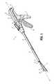
図1は、全体的に10として示される、例えば外科手術ステープル留め装置などの外科手術装置を示す。簡潔さのために、本開示は、主として外科手術ステープル留め装置10のツールアセンブリに焦点を絞る。外科手術ステープル留め装置10の残りの構成要素および使用法の詳細な考察は、米国特許第6,241,139号に開示され、この特許の開示は、参照によって本明細書により本明細書に援用される。 FIG. 1 shows a surgical device, such as a surgical stapling device, generally indicated as 10. For simplicity, the present disclosure focuses primarily on the tool assembly of surgical stapling apparatus 10. A detailed discussion of the remaining components and use of the surgical stapling apparatus 10 is disclosed in US Pat. No. 6,241,139, the disclosure of which is incorporated herein by reference. Is done.
外科手術ステープル留め装置10は、内視鏡装置であり、ハンドルアセンブリ12と、ハンドルアセンブリ12から延びる細長い本体14とを含む。ローディングユニット16は、細長い本体14の遠位端に解放可能に固定される。さらに、本開示は、装置のジョーに受け取られる交換可能カートリッジを有する外科手術ステープル留め装置を企図する。 Surgical stapling apparatus 10 is an endoscopic apparatus and includes a handle assembly 12 and an elongated body 14 extending from handle assembly 12. The
ローディングユニット16は、複数の外科手術ファスナまたはステープル84(図2を参照されたい)を収容するカートリッジアセンブリ18と、カートリッジアセンブリ18に対して並列の関係で固定されるアンビルアセンブリ20とを有するツールアセンブリ17を含み、アンビルアセンブリ20およびカートリッジアセンブリ18は、ツールアセンブリ17を閉じるように互いの方に可動であり、またはツールアセンブリ17を開くように互いに離れるように可動である。本明細書に示されるように、ローディングユニット16は、長さが約30mm〜約60mmの寸法があるローディングユニットにステープルの6つの直線列を適用するように構成される。様々なパターンで配置されるステープルポケットを有し、ステープルの任意の数の列を適用するローディングユニットおよび/または例えば45mmなどの任意の他の長さを有するローディングユニットおよびエンドエフェクタもまた想定される。ハンドルアセンブリ12は、静止ハンドル部材22と、可動ハンドル部材24と、バレル部分26とを含む。 The
回転可能部材28は、バレル部分26の前端に取り付けられ、ハンドルアセンブリ12に対する、細長い本体部分14および取り付けられたローディングユニット16の回転を容易にする。関節運動レバー30もまた、回転可能部材28に隣接してバレル部分26の前端に取り付けられ、ツールアセンブリ17の関節運動を容易にする。好ましくは、一対のノブ32が、バレル部分26に沿って可動に位置を決められる。ノブ32は、遠位に前進させられて、カートリッジアセンブリ18および/またはアンビルアセンブリ20を接近させるかまたは閉じ、近位に後退させられて、カートリッジアセンブリ18および/またはアンビルアセンブリ20を引き離すかまたは開く。 A
ローディングユニット16は、望ましくは、細長い本体14に選択可能に連結可能である。ローディングユニット16は、細長い本体14の遠位端を解放可能に係合するように適合される近位端を有するハウジング部分36を含む。取り付けアセンブリ38は、「P」においてハウジング部分36の遠位端に旋回可能に固定され、ツールアセンブリ17の「P」におけるハウジング部分36の長手方向軸に垂直な軸の周りの旋回移動が、ツールアセンブリ17の関節運動を引き起こすように、ツールアセンブリ17の近位端を受け取るように構成される。 The
概して図2を参照すると、ローディングユニット16は、取り付けアセンブリ40を含む。取り付けアセンブリ40は、上部取り付け部分40aと、下部取り付け部分40bとを含む。軸方向駆動アセンブリ50は、カートリッジアセンブリ18および/またはアンビルアセンブリ20に動作可能に関連付けられ、カートリッジアセンブリ18とアンビルアセンブリ20との間にスライド可能に配置される。図2を参照すると、軸方向駆動アセンブリ50は、遠位端54と、近位端56とを有する細長い駆動ビーム52を含む。駆動ビーム52は、単一のシートの材料または好ましくは複数の積み重ねシートの材料から組み立てられ得る。 Referring generally to FIG. 2, the
駆動アセンブリ50の駆動ビーム52の近位端56は、プッシャを受け取る一対の弾性係合フィンガを含む。プッシャは、ローディングユニット16の近位端が外科手術ステープル留め装置10の細長い本体14に係合されている場合、例えば駆動ロッドまたは制御ロッド(図示されていない)などの駆動部材を取り付けるように係合するための寸法と構成を有する。制御ロッドは、ハンドルアセンブリ12から駆動アセンブリ50の軸方向の動きを伝えるように機能する。 The proximal end 56 of the
駆動アセンブリ50の駆動ビーム52の遠位端54は、横に延びる上部分64aと、横に延びる下部分64bと、中央壁部分62とを有するヘッド60を含む。中央壁部分62の遠位縁は、ナイフブレードまたは類似のもの66を規定する。 The distal end 54 of the
図2に見られるように、アンビルアセンブリ20は、複数のステープル変形ポケット/空洞(図示されていない)を有するアンビルプレート70と、アンビルプレート70の上部表面に固定されるカバープレート72とを含み、アンビルプレート70とカバープレート72との間に規定される空洞(図示されていない)を有する。アンビルプレート70とカバープレート72との間に規定される空洞は、空洞内にヘッド60の上部分64aを受け取るように寸法設定される。長手方向スロット70bは、アンビルプレート70を通って延びて、ヘッド60の中央壁部分62がアンビルプレート70を通過することを容易にする。さらに、カバープレート72は、カバープレート72がアンビルプレート70とともに組み立てられた場合、アンビルプレート70に形成される近位の対の凹部70dと整列する、カバープレート72に形成される一対の向かい合う凹部72aを規定する。 As seen in FIG. 2, the
引き続き図2を参照すると、アンビルプレート70は、アンビルプレート70の近位端の近くに形成され、各々が長手方向スロット70bの向かい合う側に配置される近位の対の凹部70dを規定する。アンビルプレート70は、アンビルプレート70の遠位の端の近くに形成され、各々が長手方向スロット70bの向かい合う側に配置される遠位対の凹部70eを規定する。一実施形態において、近位の対の凹部70dおよび遠位の対の凹部70eの各々の凹部のうちの少なくとも1つは、好ましくは非円形状で、くびれているか、またはアンカ「S」を摩擦で係合しかつ/または締め付けるように幅減少の寸法を有する。 With continued reference to FIG. 2,
本明細書において用いられる場合、用語アンカは、縫合糸、糸、テザー、ストラップ、バンド、ひも、ワイヤ、ケーブル、ファスナ、タックまたは本明細書に開示される意図された目的に適した任意の他の材料を含むが、これらに限定されないことは理解される。特定の実施形態において、アンカは、下記に考察されるステープルライン補強材料の延長部である。アンカは、ステープルライン補強材料の全体の一部を構成し得るか、または、ステープルライン補強材料と同じかもしくは類似した材料から形成され、ステープルライン補強材料に取り付けられ得る。 As used herein, the term anchor refers to sutures, threads, tethers, straps, bands, laces, wires, cables, fasteners, tacks or any other suitable for the intended purpose disclosed herein. It is understood that these materials include, but are not limited to: In certain embodiments, the anchor is an extension of the staple line reinforcement material discussed below. The anchor may constitute part of the overall staple line reinforcement material or may be formed from the same or similar material as the staple line reinforcement material and attached to the staple line reinforcement material.
図2および図2Aに見られるように、アンビルアセンブリ20は、アンカ「S」によってアンビルプレート70の下部表面または組織接触表面に動作可能に固定される外科手術アンビルバットレス「B1」、綿撒糸または類似のものをさらに含み、アンビルポケット70aの少なくともいくらかおよび/または長手方向スロット70bの長さの少なくとも一部分の上に重なる。特に、アンカ「S」は、外科手術アンビルバットレス「B1」の近位部分および近位対の凹部70dの各々の周りに堅く締められ、アンカ「S」は、外科手術アンビルバットレス「B1」の遠位部分および遠位対の凹部70eの各々の周りに堅く締められる。 As seen in FIGS. 2 and 2A, the
外科手術アンビルバットレス「B1」は、外科手術アンビルバットレス「B1」がアンビルアセンブリ20に固定された場合、アンビルプレート70の近位対の凹部70dと整列され、側面縁に形成される近位対のノッチと、アンビルプレート70の遠位対の凹部70eに整列され、外科手術アンビルバットレス「B1」の側面縁に形成される遠位対のノッチと、長手方向スロット70bに整列される、バットレス「B1」の近位縁に形成される近位ノッチとを含む。外科手術アンビルバットレス「B1」は、その遠位端から延びるトング(tongue)またはタブをさらに含み、アセンブリ工程中のアンビルアセンブリ20への外科手術アンビルバットレス「B1」の取り付けを容易にする。外科手術アンビルバットレス「B1」をアンビルアセンブリ20に固定した後かつ梱包または出荷の前に、外科手術アンビルバットレス「B1」からトングが取り外されることが企図されている。 Surgical anvil buttress “B1” is aligned with the proximal pair of recesses 70d of the
図2〜図9に見られるように、アンビルアセンブリ20は、遠位対の凹部70eと動作可能に整列する位置においてアンビルプレート70とカバープレート72との間に配置される解放アセンブリ74をさらに含む。解放アセンブリ74はガイドプレート75を含み、ガイドプレート75はそこを通って形成される弓形のスロット75aを規定する。スロット75aは、そこを通ってツール(図示されていない)を受け取るように構成され、寸法設定される。スロット75aの機能および目的は、より詳細に以下に考察される。 As seen in FIGS. 2-9, the
解放アセンブリ74は、アンビルプレート70に旋回可能に接続されたロックまたはアンカバー76(図4および図5に見られるように)および/または任意選択でカバープレート72(図2に示される)をさらに含む。アンカバー76は、本体部分76aに細長いチャネルまたはスロット76bを規定する本体部分76aと、本体部分76aの縁から延びるフィンガ76cとを含む。フィンガ76cは、複数の遠位対の凹部70eのうちの1つと動作可能に整列しており、複数の遠位対の凹部のうちのその1つは、比較的より大きな幅寸法を有する。
縫合糸解放アセンブリ74は、アンビルプレート70に旋回可能に接続されたアンカバー作動部材77(図4および図5に見られるように)および/または任意選択でカバープレート72(図2に示される)をさらに含む。作動部材77は回転の中心軸を規定する偏心カム77aを含み、回転の中心軸の周りに作動部材は回転することを可能にされる。作動部材77は、偏心カム77aの回転の中心軸に実質的に平行である方向に偏心カム77aの表面から延び、偏心カム77aの回転の中心軸から半径方向にずれているナブまたはボス77bを含む。ボス77bは、アンカバー76の細長いスロット76bにスライド可能かつ回転可能に配置される。作動部材77は、ボス77bと実質的に反対の側から偏心カム77aから実質的に接線方向に延びる解放バー77cをさらに含む。解放バー77cは、ガイドプレート75の弓形スロット75aと整列している、解放バー77cに形成されるピン77dを規定する。動作時、偏心カム77aが回転すると、リリースバー77cのピン77dはガイドプレート75の弓形スロット75aの経路沿いに辿る。 The
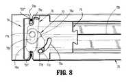
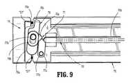
図6および図7に見られるように、縫合糸解放アセンブリ74は、係止構成または係留構成を含み、この場合、アンカバー76のフィンガ76cは、それと動作可能に整列される一対の遠位凹部70eのうちの1つの中に延びるかまたはその上に重なり、作動部材77の解放バー77cは、アンビルプレート70のナイフスロット70bを横切って延び、解放バー77cのピン77dは、ガイドプレート75の弓形スロット75aの第1の端部にまたはその近くに配置される。縫合糸解放アセンブリ74が、製造/アセンブリ工程の後、および外科手術ステープル留め装置10の完全な発射の前に、常時、ロック留め構成またはアンカ留め構成に縫合糸解放アセンブリ74を維持および/または保持する摩擦ばめ特徴またはスナップばめ特徴を含み得ることが企図されている。 As seen in FIGS. 6 and 7, the
図8および図9に見られるように、縫合糸解放アセンブリ74は、開放構成または解放構成を含み、この場合、アンカバー76のフィンガ76cは、それと動作可能に整列される一対の遠位凹部70eのうちの1つの中に延びず、またはその上に重ならず、作動部材77の解放バー77cは、アンビルプレート70のナイフスロット70bを横切って延びず、解放バー77cのピン77dは、ガイドプレート75の弓形スロット75aの第2の端部にまたはその近くに配置される。 As seen in FIGS. 8 and 9, the
縫合糸解放アセンブリ74は、外科手術の縫合糸またはテザーを用いて外科手術アンビルバットレス「B」をアンビルプレート70の組織接触表面に固定するために、外科手術ステープル留め装置10のアセンブリ工程中に製造業者によって用いられ、外科手術ステープル留め装置10の発射完了時にアンビルプレート70の組織接触表面から外科手術アンビルバットレス「B」を自動的に解放するかまたは自由にするために、外科手術ステープル留め装置10のエンドユーザによって用いられる。 The
図6〜図9を参照すると、製造工程中、縫合糸解放アセンブリ74が開放構成または解放構成の状態で(図8および図9)、外科手術アンビルバットレス「B」は、アンビルプレート70の組織接触表面の上に置かれる。次いで、外科手術縫合糸「S1」の第1の端部は、一対の遠位凹部70eのうちの一方の中に挿入され、外科手術縫合糸「S1」の第2の端部は、外科手術アンビルバットレス「B1」を横切って延ばされ(図2を参照されたい)、一対の遠位凹部70eのもう一方の中に挿入される。外科手術縫合糸「S1」の第1の端部が遠位対の凹部70eのより狭い凹部を通過しないようなサイズで作られる、結び目、ストップまたは類似のもの(図示されていない)を含み得ることが企図されている。 With reference to FIGS. 6-9, during the manufacturing process, with the
外科手術縫合糸「S1」の第2の端部が一対の遠位凹部70eに配置されている状態で、また外科手術縫合糸「S1」が外科手術アンビルバットレッス「B」を横切って緊張された(taught)状態で、ツール(図示されていない)は、ガイドプレート75の弓形のスロット75aを通って挿入され、解放バー77cのピン77dに備え付けられる開口部と係合される。図6および図7を参照すると、ツールは、ついで、ガイドプレート75の弓形スロット75aを通し、またはそれに沿って動くように操作され、それによって、解放バー77cを作動させるかまたは動かし、偏心カム77aを回転させる。偏心カム77aが回転させられると、ボス77bは、偏心カム77aの旋回軸の周りに回転させられ、アンカバー76の細長いスロット76bの壁に作用し、それによって、アンカバー76を旋回させる。アンカバー76が旋回させられると、アンカバー76のフィンガ76cは、遠位凹部70eのうちの1つの中に延ばされるかまたはその上に重なり、遠位凹部70e内に配置される外科手術縫合糸の第2の端部を締め付ける。一方では、解放バー77cは、アンビルプレート70のナイフスロット70bを横切って延びる位置に動かされている。縫合糸解放アセンブリ74は、上記に説明されたように、ここで係止構成または係留構成にある。フィンガ76cと協働可能遠位凹部70eは、76アンカバーが凹部70eから離れている場合、縫合糸「S1」が容易に凹部70eの中に入り、凹部から出ることを可能にするように、比較的広いことが望ましい。アンビルプレート70の反対の側面に配置されるもう一方の遠位凹部70eは、同じサイズであり得るか、または組み立てを容易にするために、縫合糸「S1」を堅く締め、縫合糸を適切な位置に保持するため十分に小さくあり得る。 With the second end of the surgical suture “S1” disposed in the pair of
動作時において、外科手術ステープル留め装置10の発射中、外科手術アンビルバットレス「B1」がアンビルプレート70の下部表面に対して固定されている状態で、駆動アセンブリ50が前進させられると(すなわち、最近位位置から最遠位位置に動かされると)、ナイフブレード66は、近位縫合糸「S2」の中央部を切り込み、それによって、アンビルアセンブリ20から外科手術アンビルバットレス「B1」の近位端を自由にする。使用中、図9に見られるように、外科手術ステープル留め装置10の発射動作が完了に近づき、駆動アセンブリ50がアンビルプレート70のナイフスロット70bの遠位端に近づくと、駆動アセンブリ50は、解放バー77cと接触し、解放バー77c、次いで偏心カム77aをそれらの旋回軸の周りに回転するように押し進める。偏心カム77aが回転させられると、ボス77bが偏心カム77aの旋回軸の周りに回転させられ、アンカバー76の細長いスロット76bの壁に対して作用し、それによって、アンカバー76を旋回させる。アンカバー76が旋回させられると、アンカバー76のフィンガ76cは、比較的より広い遠位凹部70eから離れるように動かされ、遠位凹部70e内に配置される外科手術縫合糸「S」の第2の端部を解放させられる。外科手術縫合糸「S」の第2の端部が解放されているかまたは自由の状態で、外科手術アンビルバットレス「B1」の遠位端は、アンビルプレート70の組織接触表面から自由に分離する。 In operation, during firing of surgical stapling apparatus 10,
図1および図2に見られるように、カートリッジアセンブリ18は、細長いサポートチャネル80aを規定するキャリア80を含む。キャリア80の細長いサポートチャネル80aは、そこにステープルカートリッジ82を受け取る。ステープルカートリッジ82およびキャリア80に沿って形成される対応するタブおよびスロットは、キャリア80内にステープルカートリッジ82を保持するように機能する。ステープルカートリッジ82に形成され、ステープルカートリッジ82から延びる一対のサポートストラットは、キャリア80の側壁に置かれるように位置を決められることにより、キャリア80のサポートチャネル80a内にステープルカートリッジ82をさらに安定させる。ステープルカートリッジ82は、そこに形成され、複数のファスナ84およびプッシャ86を受け取る保持スロット82aを含む。複数の間隔を空けて置かれる長手方向スロット82bは、ステープルカートリッジ82の中を通って延びて、作動スレッド90の直立カムウェッジ90aを収容する。作動スレッド90は、中央の直立ウェッジまたは壁90bを含む。中央壁90bは、そこに形成される遠位ノッチまたはショルダ90cを規定する(図2を参照されたい)。 As seen in FIGS. 1 and 2, the cartridge assembly 18 includes a carrier 80 that defines an elongated support channel 80a. The elongated support channel 80a of the carrier 80 receives the
中央長手方向スロット82cは、ステープルカートリッジ82に形成され、ステープルカートリッジ82の長さに沿って延びて、ヘッド60の中央壁部分62がステープルカートリッジを通過することを容易にする。外科手術ステープラ10の動作中、作動スレッド90は、ステープルカートリッジ82の長手方向スロット82bを通って並進して、カムウェッジ90aを前進させてプッシャ92と順次接触させ、保持スロット82a内に垂直にプッシャ92を並進させ、スロット82aからアンビルアセンブリ20のアンビルプレート70のステープル形成空洞70aにファスナ84(例えば、ステープル)を押し進める。 A central
引き続き図1および図2を参照すると、ステープルカートリッジ82は、その近位端の近くに形成され、長手方向スロット82cの向かい合う側に1つが配置される近位対の凹部82eを規定する。ステープルカートリッジ82は、その遠位端の近くに形成され、長手方向スロット82cの向かい合う側に各々1つが配置される遠位対の凹部82fをさらに規定する。一実施形態において、凹部82eの近位対および凹部82fの遠位対の各々の凹部のうちの少なくとも1つは、好ましくは非円形状であり、くびれているか、またはさもなければ、アンカ「S」を摩擦で係合しかつ/または締め付けるように配置される。 With continued reference to FIGS. 1 and 2, the
図1および図2Bに見られるように、カートリッジアセンブリ18は、アンカ「S3」および「S4」によってステープルカートリッジ82の上部表面または組織接触表面に動作可能に固定され、ステープルポケット82aの少なくとも一部および/または長手方向スロット82cの長さの少なくとも一部分の上に重なる外科手術カートリッジバットレス「B2」、綿撒糸または類似のものをさらに含む。特に、アンカ「S4」は、外科手術カートリッジバットレス「B2」の近位部分および近位対の凹部82eの各々の周りに堅く締められ、アンカ「S3」は、外科手術バットレス「B2」の遠位部分および遠位対の凹部82fの各々の周りに締め付けられる。 As seen in FIGS. 1 and 2B, the cartridge assembly 18 is operably secured to the top surface or tissue contacting surface of the
一特定の実施形態において、各アンカ「S」の第1の端部は、近位対の凹部82eの1つの凹部を通過しないようなサイズで作られる結び目、ストップまたは類似のもの(図示されていない)を含み、各アンカ「S」の第2の端部は、少なくとも1度外科手術カートリッジバットレス「B2」を通り越して横断し、近位対の凹部82eのもう一方の凹部を通って戻る。例えば、各アンカ「S」の第2の端部は、ステープルカートリッジ82の組織接触表面に対してアンカ「S」の第2の端部を止め、外科手術カートリッジバットレス「B2」を固定するように近位対の凹部82eのもう一方の凹部において締め付けられ得るかまたは堅く締められ得る。同様に、アンカ「S3」は、外科手術カートリッジバットレス「B2」を横断し、遠位対の凹部82fと係合するように延びるために用いられる。 In one particular embodiment, the first end of each anchor “S” has a knot, stop or the like (not shown) sized to not pass through one recess of the proximal pair of recesses 82e. The second end of each anchor “S” at least once past the surgical cartridge buttress “B2” and back through the other recess of the proximal pair of recesses 82e. For example, the second end of each anchor “S” stops the second end of the anchor “S” against the tissue contacting surface of the
さらなる実施形態において、解放アセンブリは、縫合糸「S」を切断するように配置される。ガイドプレート75上の弓形スロット75aは、それがアンカバー95を縫合糸「S」の方に駆動するように配置されるように反対の方向に延びる。縫合糸Sに面しているアンカバー76の表面は、鋭利な縁を含み、駆動アセンブリによって作動させられた場合、縫合糸を切断する。 In a further embodiment, the release assembly is arranged to cut suture “S”. The
外科手術カートリッジバットレス「B2」は、外科手術カートリッジバットレス「B2」がステープルカートリッジ82に固定された場合、ステープルカートリッジ82の近位対の凹部82eと整列される、側面縁に形成される近位対のノッチと、ステープルカートリッジ82の遠位対の凹部82fに整列される、外科手術カートリッジバットレス「B2」の側面縁に形成される遠位対のノッチと、長手方向スロット82cに整列される、バットレス「B2」の近位縁に形成される近位ノッチとを含む。外科手術カートリッジバットレス「B2」は、その遠位端から延びるトングまたはタブをさらに含み、アセンブリ工程中、ステープルカートリッジ82への外科手術カートリッジバットレス「B2」の取り付けを容易にする。外科手術カートリッジバットレス「B2」の幅がその近位部分において減少させられ得ることが企図されている。外科手術カートリッジバットレス「B2」をステープルカートリッジ82に固定した後かつ梱包または出荷の前に、外科手術カートリッジバットレス「B2」からトングが取り外されることがさらに企図されている。 Surgical cartridge buttress “B2” is a proximal pair formed at the side edges that aligns with the proximal pair of recesses 82e of
図2および図10〜図14に見られるように、カートリッジアセンブリ18は、ステープルカートリッジ82の遠位端およびその近くに支持されるカートリッジ解放アセンブリ94をさらに含む。解放アセンブリ94は、ステープルカートリッジ82に旋回可能に接続されるロックまたはアンカバー95を含む。アンカバー95は本体部分95aを含み、本体部分95aはその縁から延びるフィンガ95bを有する。フィンガ95bは、遠位対の凹部82fのうちの1つ、好ましくは比較的より大きい幅寸法を有する遠位対の凹部のうちの1つと動作可能に整列している。 As seen in FIGS. 2 and 10-14, the cartridge assembly 18 further includes a cartridge release assembly 94 supported at and near the distal end of the
解放アセンブリ94は、アンカバー95に旋回可能に接続されるアンカバー作動部材97をさらに含む(図11および図12に見られるように)。作動部材97は、作動部材97の近位縁に沿って位置を決められ、ステープルカートリッジ82の中央長手方向スロット82cを横切って延びる第1のカム表面97aと、アンカバー95のフィンガ95bに動作可能に関連付けられる遠位対の凹部82fのうちの1つに近接している作動部材97から、遠位かつ横に延びる第2の偏心カム表面97bとを含む。作動部材97の第1のカム表面97aは、実質的に弓形または凸状である。作動部材97は、アパーチャまたは開口部97cを規定し、アパーチャまたは開口部97cは、アンカバー95および作動部材97が互いに対して旋回するかまたは回転するようにアパーチャまたは開口部97cにアンカバー95のピン95cを受け取るための寸法と構成を有する。 Release assembly 94 further includes an uncover
動作時、第1の方向への作動部材97のその旋回点の周りの回転は、結果として、第2のカム表面97bがステープルカートリッジ82の表面82gに対して押し付け(図13および図14を参照されたい)、従って、少なくとも部分的に、フィンガ95bに関連付けられた遠位対の凹部82fのうちの1つの上を、および/またはそれを横切ってフィンガ95bを動かす。 In operation, rotation of the actuating
図13に見られるように、縫合糸解放アセンブリ94は、ロック留め構成またはアンカ留め構成を含み、この場合、作動部材97の第1のカム表面97aは、ステープルカートリッジ82の中央長手方向スロット82cの中にかつそこを横切って延び、この場合、作動部材97の第2のカム表面97bはステープルカートリッジ82の表面82gに対して押し付けられ、従って、アンカバー95のフィンガ95bは、それと動作可能に整列している一対の遠位凹部82fのうちのそれぞれの1つの中に延びるかまたはその上に重なる。ファスナ解放アセンブリ94は、ロック構成またはアンカ留め構成に作動部材97を保つような態様で、作動部材97を係合する付勢部材またはデテントによって、ロック留め構成またはアンカ留め構成に維持され得る。そのようなロック構成またはアンカ留め構成において、縫合糸「S3」は、ステープルカートリッジ82の凹部82fの中に押し進められ得る。縫合糸解放アセンブリ94が、製造/アセンブリ工程の後、かつ外科手術ステープル留め装置10の発射完了の前に、常時、ロック留め構成またはアンカ留め構成に縫合糸解放アセンブリ94を維持および/または保持する摩擦ばめ特徴またはスナップばめ特徴を含み得ることが企図されている。 As can be seen in FIG. 13, the suture release assembly 94 includes a locking or anchoring configuration, in which case the
図12および図14に見られるように、縫合糸解放アセンブリ94は、開放構成または解放構成を含み、この場合、アンカバー95のフィンガ95bは、それと動作可能に整列している一対の遠位凹部82fのうちのそれぞれの1つの中に延びず、またはその上に重ならず、作動部材97の第1のカム表面97aは、ステープルカートリッジ82の中央長手方向スロット82c中におよびそれを横切って延びず、作動部材97の第2のカム表面97bは、ステープルカートリッジ82の表面82gに対して押し付けられない。 As seen in FIGS. 12 and 14, the suture release assembly 94 includes an open or release configuration, wherein the fingers 95b of the uncover 95 are a pair of distal recesses operatively aligned therewith. The
縫合糸解放アセンブリ94は、アンカ、外科手術縫合糸、またはテザー「S」を用いて外科手術カートリッジバットレス「B2」(図2を参照されたい)をステープルカートリッジ82の組織接触表面に固定するために、外科手術ステープル留め装置10のアセンブリ工程中に製造業者によって用いられ、外科手術ステープル留め装置10の発射完了時にステープルカートリッジ82の組織接触表面から外科手術カートリッジバットレス「B2」を自動的に解放するかまたは自由にするために、外科手術ステープル留め装置10のエンドユーザによって用いられる。 The suture release assembly 94 is used to secure the surgical cartridge buttress “B2” (see FIG. 2) to the tissue contacting surface of the
図10〜図14を参照すると、製造工程中、縫合糸解放アセンブリ94が開放構成または解放構成の状態で、外科手術カートリッジバットレス「B2」は、ステープルカートリッジ82の組織接触表面の上に置かれる。次いで、外科手術縫合糸「S」の第1の端部は、一対の遠位凹部82fのうちの比較的より狭い方の中に挿入され、外科手術縫合糸「S」の第2の端部は、外科手術カートリッジバットレス「B2」を横切って延ばされ、一対の遠位凹部82fの比較的より広い方の中に挿入される。外科手術縫合糸「S」の第1の端部が遠位対の凹部82fのより狭い凹部を通過しないようなサイズで作られる、結び目、ストップまたは類似のもの(図示されていない)を含み得ることが企図されている。 10-14, the surgical cartridge buttress “B2” is placed over the tissue contacting surface of the
図11に見られるように、ステープルカートリッジ82は、そこに形成されるアクセス開口部83を含み、アクセス開口部83は、そこに縫合糸解放アセンブリ94を挿入しそして受け取り、アクセス部材97へのアクセスを提供するために用いられる。外科手術縫合糸「S」の第2の端部が一対の遠位凹部82fの比較的より広い方に配置されている状態、および外科手術縫合糸「S」が外科手術カートリッジバットレッス「B2」を横切って緊張された状態で、作動部材97は、旋回軸の周りに回転させられ、作動部材97の第1のカム表面97aにステープルカートリッジ82の長手方向スロット82cの中にそしてそれを横切って延ばさせ、作動部材97の第2のカム表面97bにステープルカートリッジ82の表面82g(図13および図14を参照されたい)に対して押し付けさせる。そのようにする際、アンカバー95は、アンカバー95のフィンガ95bがそれと動作可能に整列される一対の遠位凹部82fの1つの中に延びるかまたはその上に重なり、それによって、遠位凹部82fに配置される外科手術縫合糸の第2の端部を締め付ける量だけ旋回させられる。上記に説明されたように、縫合糸解放アセンブリ94は、ここで係止構成または係留構成にある。 As seen in FIG. 11, the
動作時において、外科手術ステープル留め装置10の発射中、外科手術カートリッジバットレス「B1」がステープルカートリッジ82の組織接触表面に対して固定されている状態で、駆動アセンブリ50が前進させられると(すなわち、最近位位置から最遠位位置に動かされると)、ナイフブレード66は、近位縫合糸「S4」の中央部を切り込み、それによって、ステープルカートリッジ82から外科手術カートリッジバットレス「B2」の近位端を自由にする。使用中、図14に見られるように、外科手術ステープル留め装置10の発射動作が完了に近づき、駆動アセンブリ50がステープルカートリッジ82の中央長手方向スロット82cの遠位端に近づくと、駆動アセンブリ50は、作動部材97の第1のカム表面97aと接触し、作動部材97が回転するように押し進める。作動部材97の第2のカム表面97bもまた、アンカバー95の旋回ピン95cの旋回軸の周りに回転する。偏心第2カム表面97bが第2カム表面97bの旋回軸の周りに回転させられると、旋回ピン95cとステープルカートリッジ82の表面82gとの間の距離は、減少させられ、それによって、旋回ピン95cの周りにアンカバー95を旋回させる。アンカバー95が旋回させられると、アンカバー95のフィンガ95cは、比較的より広い遠位凹部82fから離れるように動かされ、遠位凹部82f内に配置される外科手術縫合糸「S」の第2の端部を解放させられる。外科手術縫合糸「S」の第2の端部が解放されているかまたは自由の状態で、外科手術カートリッジバットレス「B2」の遠位端は、ステープルカートリッジ82の組織接触表面から自由に分離する。アンカバー95のフィンガ95bと動作可能に整列される遠位凹部82fは、アンカバー95の回転にも関わらず、縫合糸「S3」が遠位凹部82f内において堅く締められないように寸法設定される。 In operation, during firing of the surgical stapling apparatus 10, when the
駆動アセンブリ50が近位位置から遠位位置に前進させられると、駆動アセンブリ50のナイフブレード66は、外科手術アンビルバットレス「B1」および外科手術カートリッジバットレス「B2」の両方を長手方向に切り込むかまたは切断し、それによって、バットレス「B1、B2」を実質的に半分に分割する。さらに、駆動アセンブリ50が最近位位置から最遠位位置に前進させられると、作動スレッド90の直立カムウェッジ90aは、プッシャ92を作動させ、プッシャ92に保持スロット82a内に垂直に並進させ、スロット82aからファスナ84を押し進めさせる。ファスナ84(例えば、ステープル)がステープルカートリッジ82のスロット82aから押し進められると、ファスナ84の脚は、外科手術アンビルバットレス「B1」と外科手術カートリッジバットレス「B2」との間にある任意の組織(図示されていない)を通って、外科手術アンビルバットレス「B1」および外科手術カートリッジバットレス「B2」の両方を貫通しかつ通過し、アンビルアセンブリ20のアンビルプレート70のステープル形成空洞70aに対してか、またはその中に形成される。バットレス「B1、B2」は、好ましくは、バットレスを分割し組織から装置を除去することを容易にする目打ちを含む。 As
本開示に従って、外科手術アンビルバットレス「B1」および/または外科手術カートリッジバットレス「B2」は、それぞれ、ローディングユニット16のアンビルアセンブリ20またはカートリッジアセンブリ18に事前装填される(すなわち、製造業者から)。ローディングユニットが発射させられた後、バットレス「B」付きかまたはバットレス「B」なしのさらなる未発射のローディングユニットが外科手術装置に装填され得る。特定の実施形態において、交換可能ローディングユニットは、キャリア80のサポートチャネルの中に挿入され得る取り外し可能カートリッジである。バットレスおよび解放アセンブリは取り外し可能カートリッジに事前装填され得、外科手術装置のユーザがアンビルアセンブリにバットレスを装填する手段が提供され得る。例えば、接着剤を有するバットレスが用いられ得る。アンビルアセンブリ20および/またはカートリッジアセンブリ18のための追加または交換のバットレス「B」は、必要に応じまたは所望により、アンビルアセンブリ20またはカートリッジアセンブリ18のいずれかに固定され得る。 In accordance with the present disclosure, surgical anvil buttress “B1” and / or surgical cartridge buttress “B2” are preloaded (ie, from the manufacturer) into
さらなる実施形態において、解放アセンブリは、縫合糸「S」を切断するように配置され得る。作動部材97上のカム表面97bは、縫合糸「S」の方にアンカバー95をカム作用するように配置され得る。縫合糸「S」に面するアンカバー97の表面は、鋭利な縁を含み得、駆動アセンブリによって作動させられた場合、縫合糸を切断し得る。 In a further embodiment, the release assembly may be arranged to cut the suture “S”. The cam surface 97b on the actuating
ここで図15〜図25を見ると、外科手術ステープル留め装置10のための、本開示の別の実施形態に従うローディングユニットが全体的に116として示される。ローディングユニット116は、ローディングユニット16と実質的に類似しており、本明細書において、単に構造および動作における相違を識別するのに必要な程度まで詳細に考察される。 Turning now to FIGS. 15-25, a loading unit for surgical stapling apparatus 10 according to another embodiment of the present disclosure is shown generally as 116. The
図15〜図20に見られるように、ローディングユニット116のアンビルアセンブリ120は、アンビルプレート170とカバープレート172との間で遠位対の凹部170eと動作可能に整列される位置に配置される縫合糸解放アセンブリ174を含む。縫合糸解放アセンブリ174は、アンビルプレート170(図18に見られるように)に旋回可能に接続されるリンクアーム175、および/または任意選択でカバープレート172を含む。リンクアーム175は、本体部分175aを含み、本体部分175aは、リンクアーム175の第1の側面縁175bに形成されるポケットまたは凹部175cと、実質的にリンクアーム175の隣接する側面または近位縁に沿って規定されるカミング表面175dとを規定する。ポケット175cは、実質的に弓形、円形状の輪郭または丸くされた輪郭を有する。図18および図20に見られるように、リンクアーム175は、アンビルアセンブリ120にリンクアーム175を旋回可能に接続するために本体部分175aから延びる旋回ピン175eを含む。 As seen in FIGS. 15-20, the
解放アセンブリ174は、リンクアーム175に旋回可能に接続され、アンビルプレート170とカバープレート172との間にスライド可能に配置されるプッシャバー177をさらに含む。プッシャバー177は、実質的に長方形の構成を有する本体部分177aと、本体部分177aの角から延び、実質的に円形状の構成または丸くされた構成を有するヘッド177bとを含む。プッシャバー177のヘッド177bは、リンクアーム175のポケット175cにおいて旋回可能接続および/または回転可能接続となるように構成されかつ寸法設定される。
図19に見られるように、縫合糸解放アセンブリ174は、非作動構成を含み、この場合、プッシャバー177は、それと動作可能に整列している一対の遠位凹部170eのうちの1つの中に延びず、またはその上に重ならず、リンクアーム175の長手方向軸は、ローディングユニット116の長手方向軸と実質的に平行に向けられる。縫合糸解放アセンブリ174が、製造/アセンブリ工程の後、および外科手術ステープル留め装置の発射完了の前に、常時、ロック留め構成またはアンカ留め構成に縫合糸解放アセンブリ174を維持および/または保持する摩擦ばめ特徴またはスナップばめ特徴を含み得ることが企図されている。 As seen in FIG. 19,
図20に見られるように、縫合糸解放アセンブリ174は、作動構成を含み、この場合、プッシャバー177は、それと動作可能に整列される一対の遠位凹部170eのうちの1つの中に延びるかまたはその上に重なり、リンクアーム175の長手方向軸は、ローディングユニット116の長手方向軸を実質的に横断する方向に向けられる。 As seen in FIG. 20, the
図15〜図20を参照すると、製造工程中、縫合糸解放アセンブリ174が非作動構成の状態で、外科手術アンビルバットレス(図示されていない)は、アンビルプレート170の組織接触表面の上に置かれる。次いで、外科手術縫合糸「S1」の第1の端部は、一対の遠位凹部170eのうちの一方の中に挿入され、外科手術縫合糸「S1」の第2の端部は、外科手術アンビルバットレス(図示されていない)を横切って延ばされ、一対の遠位凹部170eのもう一方の中に挿入される。一対の遠位凹部170eの各々がそこに配置される外科手術縫合糸「S1」を摩擦で把持するかまたは堅く締めるように開放端部のくびれスロットであることが企図されている。 Referring to FIGS. 15-20, a surgical anvil buttress (not shown) is placed over the tissue contacting surface of the
動作時において、外科手術ステープル留め装置の発射中、外科手術アンビルバットレス(図示されていない)がアンビルプレート170の下部表面に対して固定されている状態で、駆動アセンブリ150が前進させられると(すなわち、最近位位置から最遠位位置に動かされると)、ナイフブレード166は、近位縫合糸(図示されていない)の中央部を切り込み、それによって、アンビルアセンブリ120から外科手術アンビルバットレス(図示されていない)の近位端を自由にする。使用中、図20に見られるように、外科手術ステープル留め装置の発射動作が完了に近づき、駆動アセンブリ150がアンビルプレート170のナイフスロット170bの最遠位端に近づくと、駆動アセンブリ150は、リンクアーム175のカミング表面175dと接触し、従って、リンクアーム175が旋回ピンの周りを回転するかまたは旋回するように押し進め、次いでプッシャバー177がスロットの方向に並進するように押し進める。プッシャバー177が並進させられると、プッシャバー177は、縫合糸「S1」の第2の端部と接触し、それと整列される遠位端170eから縫合糸「S1」の第2の端部が出るように押し進める。外科手術縫合糸「S1」の第2の端部が遠位凹部170eから解放されるかまたは自由の状態で、外科手術アンビルバットレス「B1」の遠位端は、アンビルプレート170の組織接触表面から自由に分離する。 In operation, during firing of the surgical stapling apparatus, when the
図15、図16および図21〜図25に見られるように、ローディングユニット116のカートリッジアセンブリ118は、ステープルカートリッジ182の遠位端におよびその近くに支持されるカートリッジ解放アセンブリ194を含む。解放アセンブリ194は、リテイナ195を含み、リテイナ195は、長手方向スロット182cの遠位端の近くの位置でステープルカートリッジ182の遠位端に支持され、少なくとも部分的に長手方向スロット182cを横切って延びる。リテイナ195は、本体部分195aと、本体部分195aの表面から延びるボス195bとを含み、本体部分195aの表面に形成され、本体部分195aの側面を通って延びるチャネルまたは凹部195cを規定する。ステープルカートリッジ182に支持される場合、リテイナ195の凹部195cは、ステープルカートリッジ182の一対の遠位凹部182fのうちの1つと整列している。 As seen in FIGS. 15, 16, and 21-25, the
解放アセンブリ194は、リテイナ195のボス195bに旋回可能に接続されるヘッド部分196aを有するプッシャ部材196をさらに含む。プッシャ部材196は、ヘッド部分196aから延びる第1の脚部材196bと、一体丁番接続部196dを介して第1の脚部材196bの自由端部に接続される第2の脚部材196cとをさらに含む。プッシャ部材196は、一体丁番接続部196fを介して第2の脚部材196cの自由端部に接続されるピストン196eをさらに含む。ピストン196eは、リテイナ195の凹部195c内にスライド可能に配置され、並進可能である。特定の他の実施形態において、プッシャは、一方の端部においてカートリッジに旋回可能に接続される第1のリンクを有するリンケージアセンブリである。第1のリンクのもう一方の端部は、第2のリンクの第1の端部に旋回可能に接続される。第2のリンクの反対の第2の端部は、リテイナの凹部に制限される。 The
図24に見られるように、解放アセンブリ194は、非作動構成を含み、この場合、ピストン196eは、一対の遠位凹部182fのうちのその1つの中に延びず、またはその上に重ならず、第1の脚部材196bおよび第2の脚部材196cは、互いに対して斜めに置かれ、ステープルカートリッジ182の長手方向スロット182cに沿って近位に突き出る。縫合糸解放アセンブリ194が、製造/アセンブリ工程の後、および外科手術ステープル留め装置の発射完了の前に、常時、ロック留め構成またはアンカ留め構成に縫合糸解放アセンブリ194を維持および/または保持する摩擦ばめ特徴またはスナップばめ特徴を含み得ることが企図されている。 As seen in FIG. 24, the
図25に見られるように、縫合糸解放アセンブリ194は、作動構成を含み、この場合、ピストン196eは、それと動作可能に整列される一対の遠位凹部182fのうちのその1つの中に延びるかまたはその上に重なり、第1の脚部材196bおよび第2の脚部材196cは、実質的に共通の軸に沿って延ばされる。 As seen in FIG. 25, the
図21〜図25を参照すると、製造工程中、縫合糸解放アセンブリ194が非作動構成の状態で、外科手術カートリッジバットレス(図示されていない)は、ステープルカートリッジ182の組織接触表面の上に置かれる。次いで、外科手術縫合糸「S3」の第1の端部は、一対の遠位凹部182fのうちの一方の中に挿入され、外科手術縫合糸「S3」の第2の端部は、外科手術カートリッジバットレスを横切って延ばされ、一対の遠位凹部182fのもう一方の中に挿入される。リテイナ195に隣接する少なくとも凹部182fがそこに配置される外科手術縫合糸「S3」を摩擦で把持するかまたは堅く締めるように開放端部のくびれスロットであることが企図されている。 Referring to FIGS. 21-25, during the manufacturing process, the surgical cartridge buttress (not shown) is placed over the tissue contacting surface of the
動作時において、外科手術ステープル留め装置10の発射中、外科手術カートリッジバットレス(図示されていない)がステープルカートリッジ182の組織接触表面に対して固定されている状態で、駆動アセンブリ150が前進させられると(すなわち、最近位位置から最遠位位置に動かされると)、ナイフブレード166は、近位縫合糸(図示されていない)の中央部を切り込み、それによって、ステープルカートリッジ182から外科手術カートリッジバットレスの近位端を自由にする。使用中、図25に見られるように、外科手術ステープル留め装置10の発射動作が完了に近づき、駆動アセンブリ150がステープルカートリッジ182の中央長手方向スロット182cの遠位端に近づくと、駆動アセンブリ150は、第1の脚部材196bと第2の脚部材196cとの間の一体丁番接続部196dと接触する。駆動アセンブリ150がさらに遠位に前進させられると、駆動アセンブリ150は、一体丁番接続部196dを押し付け、第1の脚部材196bおよび第2の脚部材196cに延びるようにする。第1の脚部材196bおよび第2の脚部材196cが延びると、ピストン196eは、リテイナ195の凹部195cを通って並進させられる。ピストン196eがリテイナ195の凹部195cを通って並進させられると、ピストン196eは、縫合糸「S3」の第2の端部を係合し、それと整列される遠位凹部182fから縫合糸「S3」が出るように押し進めて、遠位凹部182fから縫合糸「S3」の第2の端部を解放する。外科手術縫合糸「S3」の第2の端部が遠位凹部182fから解放されるかまたは自由の状態で、外科手術カートリッジバットレス「B」の遠位端は、ステープルカートリッジ182の組織接触表面から自由に分離する。 In operation, during firing of surgical stapling apparatus 10,
ここで図26〜図29を見ると、外科手術ステープル留め装置10のための、本開示の別の実施形態に従うローディングユニットが全体的に216として示される。ローディングユニット216は、ローディングユニット16または116と実質的に類似しており、本明細書において、単に構造および動作における相違を識別するのに必要な程度まで詳細に考察される。 Turning now to FIGS. 26-29, a loading unit for surgical stapling apparatus 10 according to another embodiment of the present disclosure is shown generally as 216. The
図26〜図29に見られるように、ローディングユニット216のアンビルアセンブリ220は、アンビルプレート270とカバープレート272との間で遠位対の凹部270eと動作可能に整列される位置に配置される解放アセンブリ274を含む。解放アセンブリ274は、アンビルプレート270および/またはカバープレート272に旋回可能に接続されるカム275を含む。カム275は、本体部分275aを含み、本体部分275aは、卵形輪郭を有し、遠位対の凹部270eのうちの1つに動作可能に関連付けられているカム表面275bを規定する。カム275は、本体部分275aの横縁からある角度で突き出るフィンガまたはステム275cをさらに含む。 As seen in FIGS. 26-29, the
解放アセンブリ274は、アンビルプレート270とカバープレート272との間にスライド可能に配置されるプッシャ277をさらに含む。図27〜図29に見られるように、プッシャ277は、アンビルプレート270aの長手方向スロット270b内にスライド可能に配置され得る。プッシャ277は、実質的に遠位方向に延びるカムアーム277aを含む。カムアーム277aは、カム275から延びるフィンガ275cを係合しかつ/またはフィンガ275cに作用するように構成され寸法設定される。
図28に見られるように、縫合糸解放アセンブリ274は、非作動構成を含み、この場合、カム275の本体部分275aは、それと動作可能に整列される一対の遠位凹部270eのうちの1つの中に延びず、またはその上に重ならず、プッシャ277は、後退位置または非前進位置にある。図28に見られるように、プッシャ277のカムアーム277aは、フィンガ275cに隣接し、必ずしもそうとは限らないが、カム275のフィンガ275cと接触し得る。 As seen in FIG. 28, the
図29に見られるように、縫合糸解放アセンブリ274は、作動構成を含み、この場合、カム275の本体部分275aは、それと動作可能に整列される一対の遠位凹部270eのうちの1つの中に延びるかまたはその上に重なり、プッシャ277は、前進位置にある。図29に見られるように、プッシャ277が前進位置にある場合、プッシャ277のカムアーム277aは、カム275のフィンガ275cを係合して、カム275の本体部分275aを回転させる。 As seen in FIG. 29, the
動作時において、外科手術ステープル留め装置の発射中、外科手術アンビルバットレス(図示されていない)がアンビルプレート270の下部表面に対して固定されている状態で、駆動アセンブリ250がアンビルプレート270のナイフスロット270bの最遠位端に近づくと、駆動アセンブリ250は、プッシャ277と接触し、従ってプッシャ277を遠位に駆動する。プッシャ277が遠位に駆動されると、図28および図29に見られるように、プッシャ277のカムアーム277aは、カム275のフィンガ275cを係合して、カム275を回転させるかまたは旋回させる。カム275が回転させられると、カム275のカム表面275bは、縫合糸「S1」の第2の端部と接触し、それと整列される遠位端凹部270eから縫合糸「S1」の第2の端部が出るように押し進めて、遠位凹部270eから縫合糸「S1」の第2の端部を解放する。外科手術縫合糸「S1」の第2の端部が遠位凹部270eから解放されるかまたは自由の状態で、外科手術アンビルバットレスの遠位端は、アンビルプレート270の組織接触表面から自由に分離する。 In operation, during firing of the surgical stapling apparatus, the
ここで図30〜図31を見ると、外科手術ステープル留め装置10のための、本開示の別の実施形態に従うローディングユニットが全体的に316として示される。ローディングユニット316は、ローディングユニット16、116または216と実質的に類似しており、本明細書において、単に構造および動作における相違を識別するのに必要な程度まで詳細に考察される。 Turning now to FIGS. 30-31, a loading unit according to another embodiment of the present disclosure for the surgical stapling apparatus 10 is shown generally as 316. The
図30〜図31に見られるように、ローディングユニット316のアンビルアセンブリ320は、アンビルプレート370とカバープレートとの間で遠位対の凹部370eと動作可能に整列される位置に配置される解放アセンブリ374を含む。解放アセンブリ374は、アンビルプレート370a長手方向スロット370b内にスライド可能に配置される本体部分374aを含む。解放アセンブリ374は、本体部分374aの遠位表面に接続されるかまたはそこから延びるヘッド部分374bをさらに含む。ヘッド部分374bは、その側面縁に沿ってカム表面374cを規定し、カム表面374cは、アンビルプレート370aに形成される遠位対の凹部370eのうちの1つと動作可能に関連付けられるように構成されかつ寸法設定される。カム表面374cは、弓形、湾曲または正弦曲線の輪郭を有し得る。 As seen in FIGS. 30-31, the
図30に見られるように、縫合糸解放アセンブリ374は、非作動構成を含み、この場合、本体部分374aは後退させられ、カム表面374cは、それと動作可能に整列される一対の遠位凹部370eのうちのその1つの中に延びず、またはそれを横切るように延びない。 As seen in FIG. 30, the
図31に見られるように、縫合糸解放アセンブリ374は、作動構成を含み、この場合、本体部分374aは、遠位に前進させられ、カム表面374cは、それと動作可能に整列される一対の遠位凹部370eのうちの1つの中に延びるかまたはその上に重なる。 As seen in FIG. 31, the
動作時において、外科手術ステープル留め装置の発射中、外科手術アンビルバットレス(図示されていない)がアンビルプレート370の下部表面に対して固定されている状態で、図30および図31に見られるように、駆動アセンブリ350がアンビルプレート370のナイフスロット370bの最遠位端に近づくと、駆動アセンブリ350は、解放アセンブリ374の本体部分374aと接触し、従ってヘッド部分374bを遠位に駆動する。ヘッド部分374bが遠位に駆動されると、カム表面374cは、縫合糸「S1」の第2の端部と接触し、それと整列される遠位端凹部370eから縫合糸「S1」の第2の端部が出るように押し進めて、遠位凹部370eから縫合糸「S1」の第2の端部を解放する。外科手術縫合糸「S10」の第2の端部が遠位凹部370eから解放されるかまたは自由の状態で、外科手術アンビルバットレスの遠位端は、アンビルプレート370の組織接触表面から自由に分離する。 In operation, as seen in FIGS. 30 and 31, with the surgical anvil buttress (not shown) secured to the lower surface of the anvil plate 370 during firing of the surgical stapling apparatus. As
さらなる実施形態において、駆動ヘッド部分は、カム表面374cの代わりに鋭利な縁を含み得る。駆動ヘッド部分が遠位に動くと、縫合糸「S1」は、駆動ヘッド部分の鋭利な縁と遠位凹部370eの側面との間に捉えられ、縫合糸「S1」を切断する。 In further embodiments, the drive head portion may include a sharp edge instead of the
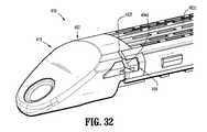
ここで図32〜図38を見ると、外科手術ステープル留め装置10のための、本開示の別の実施形態に従うローディングユニットが全体的に416として示される。ローディングユニット416は、ローディングユニット16、116、216または316と実質的に類似しており、本明細書において、単に構造および動作における相違を識別するのに必要な程度まで詳細に考察される。 Turning now to FIGS. 32-38, a loading unit for surgical stapling apparatus 10 according to another embodiment of the present disclosure is shown generally as 416. The
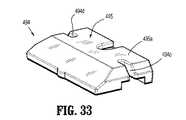
図32〜図38に見られるように、ローディングユニット416のカートリッジアセンブリ418は、ステープルカートリッジ482の遠位端におよびその近くに支持されるカートリッジ解放アセンブリ494を含む。解放アセンブリ494は、リテイナ495を含み、リテイナ495は、長手方向スロット482cの遠位端の近くの位置でステープルカートリッジ482の遠位端に支持され、少なくとも部分的に長手方向スロット482cを横切って延びる。リテイナ495は、本体部分495aと、本体部分495aの表面から延びるボス495bとを含み、本体部分495aの表面に形成され本体部分495aの側面を通って延びるチャネルまたは凹部495cを規定する。リテイナ495の本体部分495aは、本体部分495aの向かい合う側面に形成されるスロット495dを規定し、スロット495dは、そこに縫合糸を受け取るように構成される。ステープルカートリッジ482に支持される場合、リテイナ495の凹部495cはステープルカートリッジ482の一対の遠位凹部482fのうちの1つと整列され、リテイナ495のスロット495dはステープルカートリッジ482の一対の遠位凹部482fと整列される(図32を参照されたい)。 As seen in FIGS. 32-38, the
解放アセンブリ494は、リテイナ495のボス495bに旋回可能に接続されるヘッド部分496aを有するカム部材496をさらに含む。カム部材496は、ヘッド部分496aから延びる本体部分496bをさらに含む。本体部分496bは、第1のカム表面496cと、第2のカム表面496dとを規定し、それらのカム表面の各々は、カム部材496の回転軸に実質的に接して延びている。
解放アセンブリ494は、リテイナ495のチャネル495c内にスライド可能に配置されるスレッド497をさらに含む。スレッド497は、本体部分497aを含み、本体部分は、カム部材496の第2のカム表面496dを動作可能に係合するように向けられるカム表面497bと、リテイナ495の凹部495cと整列されるステープルカートリッジ482の一対の遠位凹部482fのうちの1つと整列される側壁497cとを規定する。
図37に見られるように、解放アセンブリ494は、非作動構成を含み、この場合、カム部材496の第1のカム表面496cはステープルカートリッジ482の長手方向スロット482cを横切って延び、スレッド497の側壁497cはそれと整列されるステープルカートリッジ482の一対の遠位凹部482fのうちの1つの中にまたはその上に延びず、カム部材496の第2のカム表面496dはスレッド497のカム表面497bと実質的に同一平面である。 As seen in FIG. 37, the
図38に見られるように、解放アセンブリ494は、作動構成を含み、この場合、カム部材496の第1のカム表面496cは実質的にステープルカートリッジ482の長手方向スロット482cを横切って延びず、スレッド497の側壁497cはそれと整列しているステープルカートリッジ482の一対の遠位凹部482fのうちの1つの中にまたはその上に延び、カム部材496の第2のカム表面496dはスレッド497のカム表面497bから間隔を空けて離れて置かれる。 As seen in FIG. 38, the
図32〜図38を参照すると、製造工程中、縫合糸解放アセンブリ494が非作動構成の状態で、外科手術カートリッジバットレス(図示されていない)は、ステープルカートリッジ482の組織接触表面の上に置かれる。次いで、外科手術縫合糸「S3」の第1の端部は、一対の遠位凹部482fのうちの一方の中に挿入され、外科手術縫合糸「S3」の第2の端部は、外科手術カートリッジバットレスを横切って延ばされ、一対の遠位凹部482fのもう一方の中に挿入される。側壁497cに隣接する少なくとも遠位凹部482fがそこに配置される外科手術縫合糸「S3」を摩擦で把持するかまたは堅く締めるように開放端部のくびれスロットであることが企図されている。 With reference to FIGS. 32-38, a surgical cartridge buttress (not shown) is placed over the tissue contacting surface of the
動作時において、外科手術ステープル留め装置の発射中、外科手術カートリッジバットレス(図示されていない)がステープルカートリッジ482の組織接触表面に対して固定されている状態で、図38に見られるように、駆動アセンブリ450がステープルカートリッジ482の中央長手方向スロット482cの遠位端に近づくと、駆動アセンブリ450は、ステープルカートリッジ482の長手方向スロット482cを横切って延びるカム部材496の第2のカム表面496cと接触する。 In operation, during firing of the surgical stapling apparatus, the surgical cartridge buttress (not shown) is driven against the tissue contacting surface of the
駆動アセンブリ450がさらに遠位に前進させられると、駆動アセンブリ450は、カム部材496の第1のカム表面496cを押し付け、カム部材496に回転させる。カム部材496が回転させられると、カム部材496の第2のカム表面496dはスレッド497のカム表面497bに接触しそれに対して押し付け、従ってスレッド497にリテイナ495の凹部495cにおいて並進させる。スレッド497が凹部495cを通って並進させられると、スレッド497の側壁497cは縫合糸「S3」の第2の端部を係合し、それと整列される遠位凹部482fから縫合糸「S3」が出るように押し進め、縫合糸「S3」の第2の端部を遠位凹部482fから解放する。外科手術縫合糸「S3」の第2の端部が遠位凹部482fから解放されるかまたは自由の状態で、外科手術カートリッジバットレスの遠位端は、ステープルカートリッジ482の組織接触表面から自由に分離する。 As
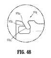
ここで図39〜図44を見ると、別の実施形態に従う外科手術ステープル留め装置は、ハウジングと、ハウジングによって支持されるハンドルと、ハウジングから遠位に延びる細長い本体と、細長い本体の遠位端にツールアセンブリとを有する。ツールアセンブリは、複数の外科手術ファスナを有するカートリッジを含むカートリッジアセンブリと、カートリッジアセンブリと並列の関係にあるアンビルアセンブリとを有する。カートリッジアセンブリおよびアンビルアセンブリのうちの少なくとも一方は、カートリッジアセンブリおよびアンビルアセンブリのうちの他方に対して可動である。カートリッジアセンブリは組織接触表面を有し、アンビルアセンブリは組織接触表面を有する。アンビルアセンブリ520は、アンビルアセンブリ120と実質的に類似しており、本明細書において、単に構造および動作における相違を識別するのに必要な程度まで詳細に考察される。アンビルアセンブリ520はアンビルプレート570を有し、アンビルプレート570は、第1のアンカを受け取る一対の向かい合う遠位側面スロットと、第2のアンカを受け取る一対の向かい合う近位側面スロットとを規定する。バットレスは、アンビルアセンブリの組織接触表面に解放可能に固定される。駆動アセンブリは、近位位置から遠位位置にツールアセンブリを通ってスライド可能に並進可能である。ツールアセンブリは交換可能ローディングユニット116の一部を形成し得るか(図15〜図25を参照されたい)、または装置は交換可能ステープルカートリッジを含み得る。 39-44, a surgical stapling apparatus according to another embodiment includes a housing, a handle supported by the housing, an elongate body extending distally from the housing, and a distal end of the elongate body. And a tool assembly. The tool assembly has a cartridge assembly that includes a cartridge having a plurality of surgical fasteners and an anvil assembly in parallel relationship with the cartridge assembly. At least one of the cartridge assembly and the anvil assembly is movable relative to the other of the cartridge assembly and the anvil assembly. The cartridge assembly has a tissue contacting surface and the anvil assembly has a tissue contacting surface. Anvil assembly 520 is substantially similar to
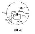
図39および図40に見られるように、アンビルアセンブリ520は、アンビルプレート570とカバープレート572との間でアンビルプレート570の遠位対の凹部570eと動作可能に整列される位置に配置される解放アセンブリ574を含む。解放アセンブリ574は、アンビルプレート570に旋回可能に接続されるリンクアーム575を含む。リンクアーム575は、本体部分575aを含み、本体部分575aは、その第1の側面縁575bに形成されるポケットまたは凹部575cと、実質的に本体部分575aの隣接する側面または近位縁に沿って規定されるカミング表面575dとを規定する。ポケット575cは、実質的に円形状の輪郭を有し、本体部分575aの側壁に規定される弓形リリーフ575eを規定する。 As seen in FIGS. 39 and 40, the anvil assembly 520 is disposed between the
解放アセンブリ574は、リンクアーム575に旋回可能に接続され、アンビルプレート570とカバープレート572との間にスライド可能に配置されるプッシャバー577をさらに含む。プッシャバー577は、実質的に長方形の構成を有する本体部分577aと、本体部分577aの角から延び、実質的に円形状または丸くされた構成を有するヘッド577bとを含む。プッシャバー577の本体部分577aは、アンビルプレート570の表面570fに対して重なり合うように構成される弓形の遠位表面または壁577cを規定する。プッシャバー577のヘッド577bは、リンクアーム575のポケット575c内に旋回可能および/または回転可能に接続するように構成されかつ寸法設定される。プッシャバー577のヘッド577bは、その側面縁からリンクアーム575のポケット575cの弓形リリーフ575eの中に突き出るストップ部材577dを含む。リンクアーム575に対するプッシャバー577の回転の相対距離は、弓形リリーフ575eの相対長さおよびストップ部材577dの相対幅によって決定される。
ここで図41〜図46を見ると、本実施形態に従って、アンビルアセンブリ520は、アンビルプレート570の近位端の近くに形成され、各々1つが長手方向スロット570bの向かい合う側に配置される近位対の凹部570dを規定する。アンビルプレート570は、アンビルプレート570の遠位端の近くに形成され、各々1つが長手方向スロット570bの向かい合う側に配置される遠位対の凹部570eを規定する。一実施形態において、近位対の凹部570dおよび遠位対の凹部570eのうちの少なくとも1つは、キーホール形状のスロット/凹部の形式である。 41-46, in accordance with this embodiment, anvil assemblies 520 are formed proximate to the proximal end of
特に、図44に見られるように、近位対の凹部570dのうちの少なくとも1つは、均一幅の中央部分570d1と、中央部分570d1の一端部に配置され、アンビルプレート570の側面縁569を越えて外に開いている、拡張または拡幅の口部分570d2と、中央部分570d3の反対の端部に配置される拡大ヘッド部分570d3とを規定する。凹部570dの中央部分570d1は第1の幅W1を規定し、拡大ヘッド部分570d3は第1の幅W1よりも大きい第2の幅W2を規定する。拡大ヘッド部分570d3は、凹部の中央部分と連絡する、円形形状、または細長い形状、または長方形形状を有し得る。近位対の凹部570dのうちの1つまたは両方は、凹部(単数または複数)が側面縁と直角になるようにアンビルプレートの側面縁から延び得るか、または近位対の凹部570dのうちの1つまたは両方は、凹部(単数または複数)が側面縁に対して斜めに置かれるようにアンビルプレートの側面縁569から延び得る。拡大ヘッド部分570d3の周りの領域は、リリーフ領域571である。In particular, as seen in Figure 44, at least one of the
図43に見られるように、遠位対の凹部570eのうちの少なくとも1つは、均一幅の中央部分570e1と、中央部分570e1の一端部に配置され、アンビルプレート570の側面縁569を越えて外に開いている、拡張または拡幅の口部分570e2と、中央部分570e3の反対の端部に配置される拡大ヘッド部分570e3とを規定する。凹部570eの中央部分570e1は第1の幅W1を規定し、拡大ヘッド部分570e3は第1の幅W1よりも大きい第2の幅W2を規定する。拡大ヘッド部分570e3は、凹部の中央部分と連絡する、円形形状、または細長い形状、または長方形形状を有し得る。近位対の凹部570eのうちの1つまたは両方は、凹部(単数または複数)が側面縁と直角になるようにアンビルプレートの側面縁569から延び得るか、または近位対の凹部570eのうちの1つまたは両方は、凹部(単数または複数)が側面縁に対して斜めに置かれるようにアンビルプレートの側面縁569から延び得る。拡大ヘッド部分570e3の周りの領域は、リリーフ領域571である。As seen in FIG. 43, at least one of the distal pair of
この方法で、縫合糸は、近位対の凹部570dおよび遠位対の凹部570eの拡大ヘッド部分に置かれ、それらの幅減少部分は、縫合糸に対して外部の力が加えられることなしに縫合糸がスライディング/ウォーキングして凹部から出ることを阻止する。実施例として、幅W1が約0.009〜0.011インチであり、幅W2が約0.014〜0.016インチであり、縫合糸が約0.0165〜0.0185の直径を有することが想定される。選択される縫合糸または他のアンカのサイズに従って、他のサイズが企図されている。 In this manner, the sutures are placed in the enlarged head portions of the proximal pair of
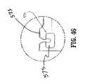
ここで図45および図46を見ると、アンビルアセンブリ520は、カバープレート572の遠位端の近くに形成されアンビルプレート570の遠位対の凹部570eと動作可能に整列され配置される遠位対の凹部572bを規定する。一実施形態において、カバープレート572の遠位対の凹部572bの各々の凹部のうちの少なくとも1つは、キーホール形状のスロット/凹部の形式である。他の実施形態において、カバープレート572の近位対の凹部のうちの少なくとも1つは、キーホール形状を有する。 45 and 46, the anvil assembly 520 is a distal pair formed near the distal end of the
図46に見られるように、遠位対の凹部572bのうちの少なくとも1つは、均一幅の中央部分572b1と、中央部分572b1の一端部に配置されカバープレート572の側面縁を越えて外に開いている拡張または拡幅の口部分572b2と、中央部分572b3の反対の端部に配置される拡大ヘッド部分572b3とを規定する。凹部572bの中央部分572b1は第1の幅W1を規定し、拡大ヘッド部分572b3は第1の幅W1よりも大きい第2の幅W2を規定する。拡大ヘッド部分572bの周りの領域は、凹部の周りのアンビルカバーの表面が段にされるようなリリーフ領域である。アンカまたは縫合糸が堅く締められた場合、堅く締められたスロットの縁はアンカまたは縫合糸を部分的に切断し、アンカまたは縫合糸にバーブ(barb)を形成する。これらのバーブは、アンカまたは縫合糸がスリップして凹部から出るのを防ぐことを助ける。さらなる実施形態において、アンビルアセンブリの近位端における一対の凹部のうちの1つまたは両方は、均一幅の中央部分と、カバープレート572の側面縁573において開いている拡幅の口部分と、拡大ヘッド部分とを含む。リリーフ領域575が、アンビルカバーの表面が段にされるように拡大ヘッド部分の周りに形成され得る。As seen in FIG. 46, at least one of the distal pair of
キーホール形状のスロットまたは凹部570d、570e、572bは、アンカの挿入および/または解放を容易にし、アンカは、上記に説明されたように、アンビルプレート70の凹部70d、70eおよびカバープレート72の凹部72bと比較して、そのスロットまたは凹部から縫合糸「S」(図示されてない)を含み得る。 The keyhole shaped slots or
キーホール形状のスロットまたは凹部が本明細書に開示される任意のアンビルアセンブリおよび/またはカートリッジアセンブリに規定される任意の側面スロットの適切な位置に備え付けられ得ることがさらに企図されている。 It is further contemplated that a keyhole shaped slot or recess may be provided at an appropriate location on any side slot defined in any anvil assembly and / or cartridge assembly disclosed herein.
駆動アセンブリは、作動させられた場合、カートリッジアセンブリおよびアンビルプレートの長手方向スロットを通って近位位置から遠位位置にツールアセンブリを通って並進する。駆動アセンブリは解放アセンブリを作動させ、解放アセンブリはアンビルプレートの凹部の各々からアンカ/縫合糸を押し出す。一旦解放アセンブリが凹部の各々からアンカ/縫合糸を押し出すと、バットレスはアンビルアセンブリから自由になる。駆動アセンブリはまた、カートリッジアセンブリからバットレスおよび留められるべき組織を通してステープルなどの外科手術ファスナを発射し得る。バットレスは留められた組織と共にとどまり、一方、外科手術ステープル留め装置は外科手術部位から除去され得る。 When actuated, the drive assembly translates through the tool assembly from a proximal position to a distal position through the longitudinal slot of the cartridge assembly and anvil plate. The drive assembly actuates the release assembly, which pushes the anchor / suture from each of the anvil plate recesses. Once the release assembly pushes the anchor / suture from each of the recesses, the buttress is free from the anvil assembly. The drive assembly may also fire a surgical fastener, such as a staple, from the cartridge assembly through the buttress and the tissue to be clamped. The buttress stays with the clamped tissue, while the surgical stapling device can be removed from the surgical site.
本開示のさらなる実施形態に従って、バットレス「B」がアンビルアセンブリおよび/またはカートリッジアセンブリの遠位および/または近位の凹部の中に挿入および/または受け取るためにバットレス「B」から延びる一体化したウィングまたはタブと共に提供されるかまたは形成され得ることが企図されている。縫合糸「S」がバットレス「B」に付着されるか、埋め込まれるかまたはさもなければ接続され得ることがさらに企図されている。 In accordance with a further embodiment of the present disclosure, an integrated wing from which buttress “B” extends from buttress “B” for insertion and / or reception into the distal and / or proximal recesses of the anvil assembly and / or cartridge assembly Or it is contemplated that it may be provided or formed with a tab. It is further contemplated that the suture “S” can be attached to, implanted or otherwise connected to the buttress “B”.
本明細書に開示される外科手術ステープル留めデバイスと共に用いる例示的バットレス「B」は、同一出願人に譲渡された米国特許第5,542,594号、第5,908,427号、第5,964,774号、および第6,045,560号、ならびに2009年10月15日に出願され、同一出願人に譲渡された米国出願第12/579,605号(現在米国特許公開第2010/0092710号)、2005年9月30日に出願され、同一出願人に譲渡された米国出願第11/241,267号(現在米国特許公開第2006/0085034号)、ならびに2005年10月12出願された米国出願第11/248,846号(米国特許公開第2006/0135992号、現在米国特許第7,823,592号)に示されかつ説明され、これらの各々の内容全体が参照によって本明細書に援用される。 An exemplary buttress “B” for use with the surgical stapling device disclosed herein is disclosed in commonly assigned US Pat. Nos. 5,542,594, 5,908,427, 5, Nos. 964,774 and 6,045,560 and U.S. Application No. 12 / 579,605 filed October 15, 2009 and assigned to the same applicant (currently U.S. Patent Publication No. 2010/0092710). No.), U.S. Application No. 11 / 241,267 (currently U.S. Patent Publication No. 2006/0085034) filed on September 30, 2005 and assigned to the same applicant, as well as filed on Oct. 12, 2005. US Patent Application No. 11 / 248,846 (U.S. Patent Publication No. 2006/0135992, now U.S. Pat. Is, the entire contents of each of which are incorporated herein by reference.
外科手術バットレス「B」は、適切な生体適合性および生体吸収性材料から製作され得る。外科手術バットレス「B」は、流体を保持しない非吸収性材料から製作され得る。外科手術バットレス「B」は、GLYCOMER 631(ブロックコポリマー)から作られる「BIOSYN」、グリコリド、ジオキサノンおよび炭酸トリメチレンから成るシンセティックポリエステルから製作され得る。 The surgical buttress “B” may be fabricated from a suitable biocompatible and bioabsorbable material. The surgical buttress “B” may be made from a non-absorbable material that does not retain fluid. Surgical buttress “B” can be made from a synthetic polyester consisting of “BIOSYN” made from GLYCOMER 631 (block copolymer), glycolide, dioxanone and trimethylene carbonate.
結果として生じるコポリマーの1ブロックは、p−ジオキサノン(1,4−ジオキサン−2−オン)および炭酸トリメチレン(1,3−ジオキサン−2−オン)由来のランダムに化合した単位量を含む。コポリマーの第2のブロックは、グリコリドおよびp−ジオキサノン由来のランダムに化合した単位量を含む。結果として生じるポリエステルは、約60%グリコリド、約14%ジオキサノン、および約26%炭酸トリメチレンを有するABA取りブロックターポリマーである。 One block of the resulting copolymer contains randomly combined unit amounts derived from p-dioxanone (1,4-dioxane-2-one) and trimethylene carbonate (1,3-dioxan-2-one). The second block of the copolymer contains randomly combined unit amounts derived from glycolide and p-dioxanone. The resulting polyester is an ABA deblocked terpolymer having about 60% glycolide, about 14% dioxanone, and about 26% trimethylene carbonate.
本明細書に開示される実施形態に対して様々な改変がなされ得ることは理解される。例えば、ステープル留め装置は、ステープルを適用する必要はなく、むしろ当技術分野において公知であるように2部ファスナを適用し得る。さらに、ステープルまたはファスナの直線列の長さは、特定の外科手術処置の要件を満たすために改変され得る。従って作動シャフトの単一の動作の長さおよび/または使い捨てローディングユニット内のステープルおよび/またはファスナの直線列の長さは、それに応じて変更され得る。従って、上記の説明は限定することとして解釈されるべきではなく、単に好ましい実施形態の例証として解釈されるべきである。当業者は、本明細書に添付された特許請求の範囲の範囲および精神内において他の改変を想定する。 It will be understood that various modifications may be made to the embodiments disclosed herein. For example, the stapling apparatus need not apply staples, but rather can apply a two-part fastener as is known in the art. In addition, the length of the linear row of staples or fasteners can be modified to meet specific surgical procedure requirements. Accordingly, the length of a single movement of the actuation shaft and / or the length of the linear row of staples and / or fasteners within the disposable loading unit can be varied accordingly. Therefore, the above description should not be construed as limiting, but merely as exemplifications of preferred embodiments. Those skilled in the art will envision other modifications within the scope and spirit of the claims appended hereto.
10 外科手術ステープル留め装置
12 ハンドルアセンブリ
14 細長い本体
16 ローディングユニット
17 ツールアセンブリ
18 カートリッジアセンブリ
20 アンビルアセンブリ
28 回転可能部材
50 駆動アセンブリ
70 アンビルプレートDESCRIPTION OF SYMBOLS 10 Surgical stapling apparatus 12 Handle assembly 14
Claims (15)
Translated fromJapanese該ハウジングによって支持されているハンドルと、
該ハウジングから遠位に延びている細長い本体と、
該細長い本体の遠位端におけるツールアセンブリであって、該ツールアセンブリは、カートリッジを含むカートリッジアセンブリであって、該カートリッジは、該カートリッジの中に複数の外科手術ファスナを有する、カートリッジアセンブリと、該カートリッジアセンブリと並列の関係にあるアンビルアセンブリとを有し、該カートリッジアセンブリおよび該アンビルアセンブリのうちの少なくとも一方は、該カートリッジアセンブリおよび該アンビルアセンブリのうちの他方に対して可動であり、該カートリッジアセンブリは組織接触表面を有し、該アンビルアセンブリは組織接触表面を有し、該アンビルアセンブリは、
アンビルプレートであって、該アンビルプレートは、第1のアンカを受け取るための一対の向かい合う遠位側面凹部と、第2のアンカを受け取るための一対の向かい合う近位側面凹部とを規定し、該一対の遠位側面凹部および該一対の近位側面凹部のうちの少なくとも1つは、キーホール形状である、アンビルプレートを含む、ツールアセンブリと、
該第1のアンカおよび該第2のアンカによって該アンビルアセンブリの組織接触表面に解放可能に固定されている、バットレスと、
近位位置から遠位位置に該ツールアセンブリを通ってスライド可能に並進可能である駆動アセンブリと
を備えている、外科手術ステープル留め装置。A housing;
A handle supported by the housing;
An elongate body extending distally from the housing;
A tool assembly at a distal end of the elongate body, the tool assembly including a cartridge, the cartridge having a plurality of surgical fasteners in the cartridge; and An anvil assembly in parallel relationship with the cartridge assembly, wherein at least one of the cartridge assembly and the anvil assembly is movable relative to the other of the cartridge assembly and the anvil assembly, the cartridge assembly Has a tissue contacting surface, the anvil assembly has a tissue contacting surface, and the anvil assembly comprises:
An anvil plate, the anvil plate defining a pair of opposing distal side recesses for receiving a first anchor and a pair of opposing proximal side recesses for receiving a second anchor. At least one of the distal side recess of the pair and the pair of proximal side recesses includes a anvil plate that is keyhole shaped;
A buttress releasably secured to a tissue contacting surface of the anvil assembly by the first anchor and the second anchor;
A surgical stapling apparatus comprising: a drive assembly slidably translatable through the tool assembly from a proximal position to a distal position.
該ハウジングによって支持されているハンドルと、
該ハウジングから遠位に延びている細長い本体と、
該細長い本体の遠位端におけるツールアセンブリであって、該ツールアセンブリは、カートリッジを含むカートリッジアセンブリであって、該カートリッジは、該カートリッジの中に複数の外科手術ファスナを有する、カートリッジアセンブリと、該カートリッジアセンブリと並列の関係にあるアンビルアセンブリとを有し、該カートリッジアセンブリおよび該アンビルアセンブリのうちの少なくとも一方は、該カートリッジアセンブリおよび該アンビルアセンブリのうちの他方に対して可動であり、該アンビルアセンブリは組織接触表面を有し、該カートリッジアセンブリは組織接触表面を有し、該アンビルアセンブリは、
アンビルプレートであって、該アンビルプレートは、第1のアンカを受け取る一対の向かい合う遠位側面凹部と、第2のアンカを受け取る一対の向かい合う近位側面凹部とを規定し、該一対の遠位側面凹部および該一対の近位側面凹部のうちの少なくとも1つは、中央部分と、該アンビルプレートの側面縁において開いている拡幅口部分と、拡大ヘッド部分とを有する、アンビルプレートを含む、ツールアセンブリと、
該第1のアンカおよび該第2のアンカによって該アンビルアセンブリの組織接触表面のうちの少なくとも1つに解放可能に固定されている、外科手術バットレスと、
近位位置から遠位位置に該ツールアセンブリを通ってスライド可能に並進可能である駆動アセンブリと
を備えている、外科手術ステープル留め装置。A housing;
A handle supported by the housing;
An elongate body extending distally from the housing;
A tool assembly at a distal end of the elongate body, the tool assembly including a cartridge, the cartridge having a plurality of surgical fasteners in the cartridge; and An anvil assembly in parallel relationship with the cartridge assembly, wherein at least one of the cartridge assembly and the anvil assembly is movable relative to the other of the cartridge assembly and the anvil assembly, the anvil assembly Has a tissue contacting surface, the cartridge assembly has a tissue contacting surface, and the anvil assembly comprises:
An anvil plate, the anvil plate defining a pair of opposing distal side recesses for receiving a first anchor and a pair of opposing proximal side recesses for receiving a second anchor, the pair of distal sides At least one of the recess and the pair of proximal side recesses includes a anvil plate having a central portion, a widening mouth portion open at a side edge of the anvil plate, and an enlarged head portion. When,
A surgical buttress releasably secured to at least one of the tissue contacting surfaces of the anvil assembly by the first anchor and the second anchor;
A surgical stapling apparatus comprising: a drive assembly slidably translatable through the tool assembly from a proximal position to a distal position.
Applications Claiming Priority (2)
| Application Number | Priority Date | Filing Date | Title |
|---|---|---|---|
| US13/097,194US8365972B2 (en) | 2009-03-31 | 2011-04-29 | Surgical stapling apparatus |
| US13/097,194 | 2011-04-29 |
Related Child Applications (1)
| Application Number | Title | Priority Date | Filing Date |
|---|---|---|---|
| JP2016218908ADivisionJP6355276B2 (en) | 2011-04-29 | 2016-11-09 | Surgical stapling device |
Publications (2)
| Publication Number | Publication Date |
|---|---|
| JP2012232121Atrue JP2012232121A (en) | 2012-11-29 |
| JP6042090B2 JP6042090B2 (en) | 2016-12-14 |
Family
ID=46044483
Family Applications (2)
| Application Number | Title | Priority Date | Filing Date |
|---|---|---|---|
| JP2012098903AExpired - Fee RelatedJP6042090B2 (en) | 2011-04-29 | 2012-04-24 | Surgical stapling device |
| JP2016218908AActiveJP6355276B2 (en) | 2011-04-29 | 2016-11-09 | Surgical stapling device |
Family Applications After (1)
| Application Number | Title | Priority Date | Filing Date |
|---|---|---|---|
| JP2016218908AActiveJP6355276B2 (en) | 2011-04-29 | 2016-11-09 | Surgical stapling device |
Country Status (5)
| Country | Link |
|---|---|
| EP (1) | EP2517638B1 (en) |
| JP (2) | JP6042090B2 (en) |
| AU (1) | AU2012201645B2 (en) |
| CA (1) | CA2773446C (en) |
| ES (1) | ES2571761T3 (en) |
Cited By (30)
| Publication number | Priority date | Publication date | Assignee | Title |
|---|---|---|---|---|
| JP2016506819A (en)* | 2013-02-08 | 2016-03-07 | エシコン・エンド−サージェリィ・インコーポレイテッドEthicon Endo−Surgery,Inc. | Fastener cartridge with releasable tissue thickness compensator |
| JP2016509524A (en)* | 2013-02-08 | 2016-03-31 | エシコン・エンド−サージェリィ・インコーポレイテッドEthicon Endo−Surgery,Inc. | Actuator for releasing a layer of material from a surgical end effector |
| JP2017023861A (en)* | 2011-04-29 | 2017-02-02 | コヴィディエン リミテッド パートナーシップ | Surgical stapling device |
| US10588633B2 (en) | 2017-06-28 | 2020-03-17 | Ethicon Llc | Surgical instruments with open and closable jaws and axially movable firing member that is initially parked in close proximity to the jaws prior to firing |
| USD879808S1 (en) | 2017-06-20 | 2020-03-31 | Ethicon Llc | Display panel with graphical user interface |
| USD879809S1 (en) | 2017-06-20 | 2020-03-31 | Ethicon Llc | Display panel with changeable graphical user interface |
| US10603039B2 (en) | 2015-09-30 | 2020-03-31 | Ethicon Llc | Progressively releasable implantable adjunct for use with a surgical stapling instrument |
| US10617418B2 (en) | 2015-08-17 | 2020-04-14 | Ethicon Llc | Implantable layers for a surgical instrument |
| US10617416B2 (en) | 2013-03-14 | 2020-04-14 | Ethicon Llc | Control systems for surgical instruments |
| US10617414B2 (en) | 2016-12-21 | 2020-04-14 | Ethicon Llc | Closure member arrangements for surgical instruments |
| US10624635B2 (en) | 2016-12-21 | 2020-04-21 | Ethicon Llc | Firing members with non-parallel jaw engagement features for surgical end effectors |
| US10624633B2 (en) | 2017-06-20 | 2020-04-21 | Ethicon Llc | Systems and methods for controlling motor velocity of a surgical stapling and cutting instrument |
| US10695063B2 (en) | 2012-02-13 | 2020-06-30 | Ethicon Llc | Surgical cutting and fastening instrument with apparatus for determining cartridge and firing motion status |
| US10772629B2 (en) | 2017-06-27 | 2020-09-15 | Ethicon Llc | Surgical anvil arrangements |
| US10779823B2 (en) | 2016-12-21 | 2020-09-22 | Ethicon Llc | Firing member pin angle |
| US10813639B2 (en) | 2017-06-20 | 2020-10-27 | Ethicon Llc | Closed loop feedback control of motor velocity of a surgical stapling and cutting instrument based on system conditions |
| US10881396B2 (en) | 2017-06-20 | 2021-01-05 | Ethicon Llc | Surgical instrument with variable duration trigger arrangement |
| US10893864B2 (en) | 2016-12-21 | 2021-01-19 | Ethicon | Staple cartridges and arrangements of staples and staple cavities therein |
| US10903685B2 (en) | 2017-06-28 | 2021-01-26 | Ethicon Llc | Surgical shaft assemblies with slip ring assemblies forming capacitive channels |
| US10918380B2 (en) | 2006-01-31 | 2021-02-16 | Ethicon Llc | Surgical instrument system including a control system |
| US11058420B2 (en) | 2006-01-31 | 2021-07-13 | Cilag Gmbh International | Surgical stapling apparatus comprising a lockout system |
| US11058424B2 (en) | 2017-06-28 | 2021-07-13 | Cilag Gmbh International | Surgical instrument comprising an offset articulation joint |
| US11064998B2 (en) | 2007-01-10 | 2021-07-20 | Cilag Gmbh International | Surgical instrument with wireless communication between a control unit of a robotic system and remote sensor |
| US11090049B2 (en) | 2017-06-27 | 2021-08-17 | Cilag Gmbh International | Staple forming pocket arrangements |
| US11382638B2 (en) | 2017-06-20 | 2022-07-12 | Cilag Gmbh International | Closed loop feedback control of motor velocity of a surgical stapling and cutting instrument based on measured time over a specified displacement distance |
| JP2022539531A (en)* | 2019-06-25 | 2022-09-12 | シラグ・ゲーエムベーハー・インターナショナル | Staple cartridge retainer with retractable authentication key |
| US11478247B2 (en) | 2010-07-30 | 2022-10-25 | Cilag Gmbh International | Tissue acquisition arrangements and methods for surgical stapling devices |
| US11534259B2 (en) | 2020-10-29 | 2022-12-27 | Cilag Gmbh International | Surgical instrument comprising an articulation indicator |
| US11607239B2 (en) | 2016-04-15 | 2023-03-21 | Cilag Gmbh International | Systems and methods for controlling a surgical stapling and cutting instrument |
| US11896217B2 (en) | 2020-10-29 | 2024-02-13 | Cilag Gmbh International | Surgical instrument comprising an articulation lock |
Families Citing this family (477)
| Publication number | Priority date | Publication date | Assignee | Title |
|---|---|---|---|---|
| US20070084897A1 (en) | 2003-05-20 | 2007-04-19 | Shelton Frederick E Iv | Articulating surgical stapling instrument incorporating a two-piece e-beam firing mechanism |
| US9060770B2 (en) | 2003-05-20 | 2015-06-23 | Ethicon Endo-Surgery, Inc. | Robotically-driven surgical instrument with E-beam driver |
| US11998198B2 (en) | 2004-07-28 | 2024-06-04 | Cilag Gmbh International | Surgical stapling instrument incorporating a two-piece E-beam firing mechanism |
| US9072535B2 (en) | 2011-05-27 | 2015-07-07 | Ethicon Endo-Surgery, Inc. | Surgical stapling instruments with rotatable staple deployment arrangements |
| US8215531B2 (en) | 2004-07-28 | 2012-07-10 | Ethicon Endo-Surgery, Inc. | Surgical stapling instrument having a medical substance dispenser |
| US11890012B2 (en) | 2004-07-28 | 2024-02-06 | Cilag Gmbh International | Staple cartridge comprising cartridge body and attached support |
| US11246590B2 (en) | 2005-08-31 | 2022-02-15 | Cilag Gmbh International | Staple cartridge including staple drivers having different unfired heights |
| US7673781B2 (en) | 2005-08-31 | 2010-03-09 | Ethicon Endo-Surgery, Inc. | Surgical stapling device with staple driver that supports multiple wire diameter staples |
| US7934630B2 (en) | 2005-08-31 | 2011-05-03 | Ethicon Endo-Surgery, Inc. | Staple cartridges for forming staples having differing formed staple heights |
| US11484312B2 (en) | 2005-08-31 | 2022-11-01 | Cilag Gmbh International | Staple cartridge comprising a staple driver arrangement |
| US7669746B2 (en) | 2005-08-31 | 2010-03-02 | Ethicon Endo-Surgery, Inc. | Staple cartridges for forming staples having differing formed staple heights |
| US10159482B2 (en) | 2005-08-31 | 2018-12-25 | Ethicon Llc | Fastener cartridge assembly comprising a fixed anvil and different staple heights |
| US9237891B2 (en) | 2005-08-31 | 2016-01-19 | Ethicon Endo-Surgery, Inc. | Robotically-controlled surgical stapling devices that produce formed staples having different lengths |
| US20070106317A1 (en) | 2005-11-09 | 2007-05-10 | Shelton Frederick E Iv | Hydraulically and electrically actuated articulation joints for surgical instruments |
| US11793518B2 (en) | 2006-01-31 | 2023-10-24 | Cilag Gmbh International | Powered surgical instruments with firing system lockout arrangements |
| US8186555B2 (en) | 2006-01-31 | 2012-05-29 | Ethicon Endo-Surgery, Inc. | Motor-driven surgical cutting and fastening instrument with mechanical closure system |
| US9861359B2 (en) | 2006-01-31 | 2018-01-09 | Ethicon Llc | Powered surgical instruments with firing system lockout arrangements |
| US8708213B2 (en) | 2006-01-31 | 2014-04-29 | Ethicon Endo-Surgery, Inc. | Surgical instrument having a feedback system |
| US8820603B2 (en) | 2006-01-31 | 2014-09-02 | Ethicon Endo-Surgery, Inc. | Accessing data stored in a memory of a surgical instrument |
| US11224427B2 (en) | 2006-01-31 | 2022-01-18 | Cilag Gmbh International | Surgical stapling system including a console and retraction assembly |
| US11278279B2 (en) | 2006-01-31 | 2022-03-22 | Cilag Gmbh International | Surgical instrument assembly |
| US20110024477A1 (en) | 2009-02-06 | 2011-02-03 | Hall Steven G | Driven Surgical Stapler Improvements |
| US20110295295A1 (en) | 2006-01-31 | 2011-12-01 | Ethicon Endo-Surgery, Inc. | Robotically-controlled surgical instrument having recording capabilities |
| US7753904B2 (en) | 2006-01-31 | 2010-07-13 | Ethicon Endo-Surgery, Inc. | Endoscopic surgical instrument with a handle that can articulate with respect to the shaft |
| US8992422B2 (en) | 2006-03-23 | 2015-03-31 | Ethicon Endo-Surgery, Inc. | Robotically-controlled endoscopic accessory channel |
| US8236010B2 (en) | 2006-03-23 | 2012-08-07 | Ethicon Endo-Surgery, Inc. | Surgical fastener and cutter with mimicking end effector |
| US8322455B2 (en) | 2006-06-27 | 2012-12-04 | Ethicon Endo-Surgery, Inc. | Manually driven surgical cutting and fastening instrument |
| US10130359B2 (en) | 2006-09-29 | 2018-11-20 | Ethicon Llc | Method for forming a staple |
| US10568652B2 (en) | 2006-09-29 | 2020-02-25 | Ethicon Llc | Surgical staples having attached drivers of different heights and stapling instruments for deploying the same |
| US7506791B2 (en) | 2006-09-29 | 2009-03-24 | Ethicon Endo-Surgery, Inc. | Surgical stapling instrument with mechanical mechanism for limiting maximum tissue compression |
| US11980366B2 (en) | 2006-10-03 | 2024-05-14 | Cilag Gmbh International | Surgical instrument |
| US11291441B2 (en) | 2007-01-10 | 2022-04-05 | Cilag Gmbh International | Surgical instrument with wireless communication between control unit and remote sensor |
| US8632535B2 (en) | 2007-01-10 | 2014-01-21 | Ethicon Endo-Surgery, Inc. | Interlock and surgical instrument including same |
| US8652120B2 (en) | 2007-01-10 | 2014-02-18 | Ethicon Endo-Surgery, Inc. | Surgical instrument with wireless communication between control unit and sensor transponders |
| US11039836B2 (en) | 2007-01-11 | 2021-06-22 | Cilag Gmbh International | Staple cartridge for use with a surgical stapling instrument |
| US20080169333A1 (en) | 2007-01-11 | 2008-07-17 | Shelton Frederick E | Surgical stapler end effector with tapered distal end |
| US7673782B2 (en) | 2007-03-15 | 2010-03-09 | Ethicon Endo-Surgery, Inc. | Surgical stapling instrument having a releasable buttress material |
| US8893946B2 (en) | 2007-03-28 | 2014-11-25 | Ethicon Endo-Surgery, Inc. | Laparoscopic tissue thickness and clamp load measuring devices |
| US8931682B2 (en) | 2007-06-04 | 2015-01-13 | Ethicon Endo-Surgery, Inc. | Robotically-controlled shaft based rotary drive systems for surgical instruments |
| US11564682B2 (en) | 2007-06-04 | 2023-01-31 | Cilag Gmbh International | Surgical stapler device |
| US7753245B2 (en) | 2007-06-22 | 2010-07-13 | Ethicon Endo-Surgery, Inc. | Surgical stapling instruments |
| US8408439B2 (en) | 2007-06-22 | 2013-04-02 | Ethicon Endo-Surgery, Inc. | Surgical stapling instrument with an articulatable end effector |
| US11849941B2 (en) | 2007-06-29 | 2023-12-26 | Cilag Gmbh International | Staple cartridge having staple cavities extending at a transverse angle relative to a longitudinal cartridge axis |
| US8561870B2 (en) | 2008-02-13 | 2013-10-22 | Ethicon Endo-Surgery, Inc. | Surgical stapling instrument |
| US7819298B2 (en) | 2008-02-14 | 2010-10-26 | Ethicon Endo-Surgery, Inc. | Surgical stapling apparatus with control features operable with one hand |
| US7866527B2 (en) | 2008-02-14 | 2011-01-11 | Ethicon Endo-Surgery, Inc. | Surgical stapling apparatus with interlockable firing system |
| US8636736B2 (en) | 2008-02-14 | 2014-01-28 | Ethicon Endo-Surgery, Inc. | Motorized surgical cutting and fastening instrument |
| US8657174B2 (en) | 2008-02-14 | 2014-02-25 | Ethicon Endo-Surgery, Inc. | Motorized surgical cutting and fastening instrument having handle based power source |
| US8758391B2 (en) | 2008-02-14 | 2014-06-24 | Ethicon Endo-Surgery, Inc. | Interchangeable tools for surgical instruments |
| US8573465B2 (en) | 2008-02-14 | 2013-11-05 | Ethicon Endo-Surgery, Inc. | Robotically-controlled surgical end effector system with rotary actuated closure systems |
| JP5410110B2 (en) | 2008-02-14 | 2014-02-05 | エシコン・エンド−サージェリィ・インコーポレイテッド | Surgical cutting / fixing instrument with RF electrode |
| US9179912B2 (en) | 2008-02-14 | 2015-11-10 | Ethicon Endo-Surgery, Inc. | Robotically-controlled motorized surgical cutting and fastening instrument |
| US11986183B2 (en) | 2008-02-14 | 2024-05-21 | Cilag Gmbh International | Surgical cutting and fastening instrument comprising a plurality of sensors to measure an electrical parameter |
| US20090206131A1 (en) | 2008-02-15 | 2009-08-20 | Ethicon Endo-Surgery, Inc. | End effector coupling arrangements for a surgical cutting and stapling instrument |
| US9585657B2 (en) | 2008-02-15 | 2017-03-07 | Ethicon Endo-Surgery, Llc | Actuator for releasing a layer of material from a surgical end effector |
| US11272927B2 (en) | 2008-02-15 | 2022-03-15 | Cilag Gmbh International | Layer arrangements for surgical staple cartridges |
| PL3476312T3 (en) | 2008-09-19 | 2024-03-11 | Ethicon Llc | Surgical stapler with apparatus for adjusting staple height |
| US7954686B2 (en) | 2008-09-19 | 2011-06-07 | Ethicon Endo-Surgery, Inc. | Surgical stapler with apparatus for adjusting staple height |
| US9386983B2 (en) | 2008-09-23 | 2016-07-12 | Ethicon Endo-Surgery, Llc | Robotically-controlled motorized surgical instrument |
| US8210411B2 (en) | 2008-09-23 | 2012-07-03 | Ethicon Endo-Surgery, Inc. | Motor-driven surgical cutting instrument |
| US9005230B2 (en) | 2008-09-23 | 2015-04-14 | Ethicon Endo-Surgery, Inc. | Motorized surgical instrument |
| US11648005B2 (en) | 2008-09-23 | 2023-05-16 | Cilag Gmbh International | Robotically-controlled motorized surgical instrument with an end effector |
| US8608045B2 (en) | 2008-10-10 | 2013-12-17 | Ethicon Endo-Sugery, Inc. | Powered surgical cutting and stapling apparatus with manually retractable firing system |
| US8517239B2 (en) | 2009-02-05 | 2013-08-27 | Ethicon Endo-Surgery, Inc. | Surgical stapling instrument comprising a magnetic element driver |
| US8453907B2 (en) | 2009-02-06 | 2013-06-04 | Ethicon Endo-Surgery, Inc. | Motor driven surgical fastener device with cutting member reversing mechanism |
| US8444036B2 (en) | 2009-02-06 | 2013-05-21 | Ethicon Endo-Surgery, Inc. | Motor driven surgical fastener device with mechanisms for adjusting a tissue gap within the end effector |
| RU2525225C2 (en) | 2009-02-06 | 2014-08-10 | Этикон Эндо-Серджери, Инк. | Improvement of drive surgical suturing instrument |
| US8220688B2 (en) | 2009-12-24 | 2012-07-17 | Ethicon Endo-Surgery, Inc. | Motor-driven surgical cutting instrument with electric actuator directional control assembly |
| US8851354B2 (en) | 2009-12-24 | 2014-10-07 | Ethicon Endo-Surgery, Inc. | Surgical cutting instrument that analyzes tissue thickness |
| US8608046B2 (en) | 2010-01-07 | 2013-12-17 | Ethicon Endo-Surgery, Inc. | Test device for a surgical tool |
| US8360296B2 (en) | 2010-09-09 | 2013-01-29 | Ethicon Endo-Surgery, Inc. | Surgical stapling head assembly with firing lockout for a surgical stapler |
| US8632525B2 (en) | 2010-09-17 | 2014-01-21 | Ethicon Endo-Surgery, Inc. | Power control arrangements for surgical instruments and batteries |
| US9289212B2 (en) | 2010-09-17 | 2016-03-22 | Ethicon Endo-Surgery, Inc. | Surgical instruments and batteries for surgical instruments |
| US8733613B2 (en) | 2010-09-29 | 2014-05-27 | Ethicon Endo-Surgery, Inc. | Staple cartridge |
| RU2013119928A (en) | 2010-09-30 | 2014-11-10 | Этикон Эндо-Серджери, Инк. | A STAPLING SYSTEM CONTAINING A RETAINING MATRIX AND A LEVELING MATRIX |
| US9220501B2 (en) | 2010-09-30 | 2015-12-29 | Ethicon Endo-Surgery, Inc. | Tissue thickness compensators |
| US9332974B2 (en) | 2010-09-30 | 2016-05-10 | Ethicon Endo-Surgery, Llc | Layered tissue thickness compensator |
| US9055941B2 (en) | 2011-09-23 | 2015-06-16 | Ethicon Endo-Surgery, Inc. | Staple cartridge including collapsible deck |
| US9301753B2 (en) | 2010-09-30 | 2016-04-05 | Ethicon Endo-Surgery, Llc | Expandable tissue thickness compensator |
| US9277919B2 (en) | 2010-09-30 | 2016-03-08 | Ethicon Endo-Surgery, Llc | Tissue thickness compensator comprising fibers to produce a resilient load |
| US11298125B2 (en) | 2010-09-30 | 2022-04-12 | Cilag Gmbh International | Tissue stapler having a thickness compensator |
| US9629814B2 (en) | 2010-09-30 | 2017-04-25 | Ethicon Endo-Surgery, Llc | Tissue thickness compensator configured to redistribute compressive forces |
| US9351730B2 (en) | 2011-04-29 | 2016-05-31 | Ethicon Endo-Surgery, Llc | Tissue thickness compensator comprising channels |
| US11925354B2 (en) | 2010-09-30 | 2024-03-12 | Cilag Gmbh International | Staple cartridge comprising staples positioned within a compressible portion thereof |
| US9364233B2 (en) | 2010-09-30 | 2016-06-14 | Ethicon Endo-Surgery, Llc | Tissue thickness compensators for circular surgical staplers |
| US9232941B2 (en) | 2010-09-30 | 2016-01-12 | Ethicon Endo-Surgery, Inc. | Tissue thickness compensator comprising a reservoir |
| US9016542B2 (en) | 2010-09-30 | 2015-04-28 | Ethicon Endo-Surgery, Inc. | Staple cartridge comprising compressible distortion resistant components |
| US9386988B2 (en) | 2010-09-30 | 2016-07-12 | Ethicon End-Surgery, LLC | Retainer assembly including a tissue thickness compensator |
| US9788834B2 (en) | 2010-09-30 | 2017-10-17 | Ethicon Llc | Layer comprising deployable attachment members |
| US10945731B2 (en) | 2010-09-30 | 2021-03-16 | Ethicon Llc | Tissue thickness compensator comprising controlled release and expansion |
| US12213666B2 (en) | 2010-09-30 | 2025-02-04 | Cilag Gmbh International | Tissue thickness compensator comprising layers |
| US11812965B2 (en) | 2010-09-30 | 2023-11-14 | Cilag Gmbh International | Layer of material for a surgical end effector |
| US9113862B2 (en) | 2010-09-30 | 2015-08-25 | Ethicon Endo-Surgery, Inc. | Surgical stapling instrument with a variable staple forming system |
| US9301752B2 (en) | 2010-09-30 | 2016-04-05 | Ethicon Endo-Surgery, Llc | Tissue thickness compensator comprising a plurality of capsules |
| US8695866B2 (en) | 2010-10-01 | 2014-04-15 | Ethicon Endo-Surgery, Inc. | Surgical instrument having a power control circuit |
| US9211122B2 (en) | 2011-03-14 | 2015-12-15 | Ethicon Endo-Surgery, Inc. | Surgical access devices with anvil introduction and specimen retrieval structures |
| AU2012250197B2 (en) | 2011-04-29 | 2017-08-10 | Ethicon Endo-Surgery, Inc. | Staple cartridge comprising staples positioned within a compressible portion thereof |
| US11207064B2 (en) | 2011-05-27 | 2021-12-28 | Cilag Gmbh International | Automated end effector component reloading system for use with a robotic system |
| CA2856346C (en) | 2011-08-18 | 2022-08-30 | Anchor Orthopedics Xt Inc. | Suture passing instrumentation and methods of use thereof |
| US9050084B2 (en) | 2011-09-23 | 2015-06-09 | Ethicon Endo-Surgery, Inc. | Staple cartridge including collapsible deck arrangement |
| US9078653B2 (en) | 2012-03-26 | 2015-07-14 | Ethicon Endo-Surgery, Inc. | Surgical stapling device with lockout system for preventing actuation in the absence of an installed staple cartridge |
| BR112014024098B1 (en) | 2012-03-28 | 2021-05-25 | Ethicon Endo-Surgery, Inc. | staple cartridge |
| MX358135B (en) | 2012-03-28 | 2018-08-06 | Ethicon Endo Surgery Inc | Tissue thickness compensator comprising a plurality of layers. |
| JP6224070B2 (en) | 2012-03-28 | 2017-11-01 | エシコン・エンド−サージェリィ・インコーポレイテッドEthicon Endo−Surgery,Inc. | Retainer assembly including tissue thickness compensator |
| US9101358B2 (en) | 2012-06-15 | 2015-08-11 | Ethicon Endo-Surgery, Inc. | Articulatable surgical instrument comprising a firing drive |
| US11278284B2 (en) | 2012-06-28 | 2022-03-22 | Cilag Gmbh International | Rotary drive arrangements for surgical instruments |
| US9072536B2 (en) | 2012-06-28 | 2015-07-07 | Ethicon Endo-Surgery, Inc. | Differential locking arrangements for rotary powered surgical instruments |
| US20140005718A1 (en) | 2012-06-28 | 2014-01-02 | Ethicon Endo-Surgery, Inc. | Multi-functional powered surgical device with external dissection features |
| US9119657B2 (en) | 2012-06-28 | 2015-09-01 | Ethicon Endo-Surgery, Inc. | Rotary actuatable closure arrangement for surgical end effector |
| US9125662B2 (en) | 2012-06-28 | 2015-09-08 | Ethicon Endo-Surgery, Inc. | Multi-axis articulating and rotating surgical tools |
| US20140001231A1 (en) | 2012-06-28 | 2014-01-02 | Ethicon Endo-Surgery, Inc. | Firing system lockout arrangements for surgical instruments |
| US9282974B2 (en) | 2012-06-28 | 2016-03-15 | Ethicon Endo-Surgery, Llc | Empty clip cartridge lockout |
| JP6290201B2 (en) | 2012-06-28 | 2018-03-07 | エシコン・エンド−サージェリィ・インコーポレイテッドEthicon Endo−Surgery,Inc. | Lockout for empty clip cartridge |
| US9101385B2 (en) | 2012-06-28 | 2015-08-11 | Ethicon Endo-Surgery, Inc. | Electrode connections for rotary driven surgical tools |
| US9561038B2 (en) | 2012-06-28 | 2017-02-07 | Ethicon Endo-Surgery, Llc | Interchangeable clip applier |
| US9289256B2 (en) | 2012-06-28 | 2016-03-22 | Ethicon Endo-Surgery, Llc | Surgical end effectors having angled tissue-contacting surfaces |
| US9408606B2 (en) | 2012-06-28 | 2016-08-09 | Ethicon Endo-Surgery, Llc | Robotically powered surgical device with manually-actuatable reversing system |
| BR112014032776B1 (en) | 2012-06-28 | 2021-09-08 | Ethicon Endo-Surgery, Inc | SURGICAL INSTRUMENT SYSTEM AND SURGICAL KIT FOR USE WITH A SURGICAL INSTRUMENT SYSTEM |
| US12383267B2 (en) | 2012-06-28 | 2025-08-12 | Cilag Gmbh International | Robotically powered surgical device with manually-actuatable reversing system |
| US9028494B2 (en) | 2012-06-28 | 2015-05-12 | Ethicon Endo-Surgery, Inc. | Interchangeable end effector coupling arrangement |
| US9386985B2 (en) | 2012-10-15 | 2016-07-12 | Ethicon Endo-Surgery, Llc | Surgical cutting instrument |
| US9386984B2 (en) | 2013-02-08 | 2016-07-12 | Ethicon Endo-Surgery, Llc | Staple cartridge comprising a releasable cover |
| RU2672520C2 (en) | 2013-03-01 | 2018-11-15 | Этикон Эндо-Серджери, Инк. | Hingedly turnable surgical instruments with conducting ways for signal transfer |
| BR112015021082B1 (en) | 2013-03-01 | 2022-05-10 | Ethicon Endo-Surgery, Inc | surgical instrument |
| US9468438B2 (en) | 2013-03-01 | 2016-10-18 | Eticon Endo-Surgery, LLC | Sensor straightened end effector during removal through trocar |
| US9345481B2 (en) | 2013-03-13 | 2016-05-24 | Ethicon Endo-Surgery, Llc | Staple cartridge tissue thickness sensor system |
| US9808244B2 (en) | 2013-03-14 | 2017-11-07 | Ethicon Llc | Sensor arrangements for absolute positioning system for surgical instruments |
| US9572577B2 (en) | 2013-03-27 | 2017-02-21 | Ethicon Endo-Surgery, Llc | Fastener cartridge comprising a tissue thickness compensator including openings therein |
| US9795384B2 (en) | 2013-03-27 | 2017-10-24 | Ethicon Llc | Fastener cartridge comprising a tissue thickness compensator and a gap setting element |
| US9332984B2 (en) | 2013-03-27 | 2016-05-10 | Ethicon Endo-Surgery, Llc | Fastener cartridge assemblies |
| US9826976B2 (en) | 2013-04-16 | 2017-11-28 | Ethicon Llc | Motor driven surgical instruments with lockable dual drive shafts |
| BR112015026109B1 (en) | 2013-04-16 | 2022-02-22 | Ethicon Endo-Surgery, Inc | surgical instrument |
| US9574644B2 (en) | 2013-05-30 | 2017-02-21 | Ethicon Endo-Surgery, Llc | Power module for use with a surgical instrument |
| MX369362B (en) | 2013-08-23 | 2019-11-06 | Ethicon Endo Surgery Llc | Firing member retraction devices for powered surgical instruments. |
| US9775609B2 (en) | 2013-08-23 | 2017-10-03 | Ethicon Llc | Tamper proof circuit for surgical instrument battery pack |
| US20150173749A1 (en) | 2013-12-23 | 2015-06-25 | Ethicon Endo-Surgery, Inc. | Surgical staples and staple cartridges |
| US9642620B2 (en) | 2013-12-23 | 2017-05-09 | Ethicon Endo-Surgery, Llc | Surgical cutting and stapling instruments with articulatable end effectors |
| US9724092B2 (en) | 2013-12-23 | 2017-08-08 | Ethicon Llc | Modular surgical instruments |
| US9839428B2 (en) | 2013-12-23 | 2017-12-12 | Ethicon Llc | Surgical cutting and stapling instruments with independent jaw control features |
| US9681870B2 (en) | 2013-12-23 | 2017-06-20 | Ethicon Llc | Articulatable surgical instruments with separate and distinct closing and firing systems |
| US20150173756A1 (en) | 2013-12-23 | 2015-06-25 | Ethicon Endo-Surgery, Inc. | Surgical cutting and stapling methods |
| US9962161B2 (en) | 2014-02-12 | 2018-05-08 | Ethicon Llc | Deliverable surgical instrument |
| US20140166724A1 (en) | 2014-02-24 | 2014-06-19 | Ethicon Endo-Surgery, Inc. | Staple cartridge including a barbed staple |
| JP6462004B2 (en) | 2014-02-24 | 2019-01-30 | エシコン エルエルシー | Fastening system with launcher lockout |
| US10004497B2 (en) | 2014-03-26 | 2018-06-26 | Ethicon Llc | Interface systems for use with surgical instruments |
| BR112016021943B1 (en) | 2014-03-26 | 2022-06-14 | Ethicon Endo-Surgery, Llc | SURGICAL INSTRUMENT FOR USE BY AN OPERATOR IN A SURGICAL PROCEDURE |
| US20150272580A1 (en) | 2014-03-26 | 2015-10-01 | Ethicon Endo-Surgery, Inc. | Verification of number of battery exchanges/procedure count |
| US9913642B2 (en) | 2014-03-26 | 2018-03-13 | Ethicon Llc | Surgical instrument comprising a sensor system |
| US12232723B2 (en) | 2014-03-26 | 2025-02-25 | Cilag Gmbh International | Systems and methods for controlling a segmented circuit |
| US10013049B2 (en) | 2014-03-26 | 2018-07-03 | Ethicon Llc | Power management through sleep options of segmented circuit and wake up control |
| US20150297225A1 (en) | 2014-04-16 | 2015-10-22 | Ethicon Endo-Surgery, Inc. | Fastener cartridges including extensions having different configurations |
| CN106456159B (en) | 2014-04-16 | 2019-03-08 | 伊西康内外科有限责任公司 | Fastener Cartridge Assembly and Nail Retainer Cover Arrangement |
| BR112016023825B1 (en) | 2014-04-16 | 2022-08-02 | Ethicon Endo-Surgery, Llc | STAPLE CARTRIDGE FOR USE WITH A SURGICAL STAPLER AND STAPLE CARTRIDGE FOR USE WITH A SURGICAL INSTRUMENT |
| US10470768B2 (en) | 2014-04-16 | 2019-11-12 | Ethicon Llc | Fastener cartridge including a layer attached thereto |
| CN106456176B (en) | 2014-04-16 | 2019-06-28 | 伊西康内外科有限责任公司 | Fastener Cartridge Including Extensions With Different Configurations |
| US10327764B2 (en) | 2014-09-26 | 2019-06-25 | Ethicon Llc | Method for creating a flexible staple line |
| US10045781B2 (en) | 2014-06-13 | 2018-08-14 | Ethicon Llc | Closure lockout systems for surgical instruments |
| US10135242B2 (en) | 2014-09-05 | 2018-11-20 | Ethicon Llc | Smart cartridge wake up operation and data retention |
| US11311294B2 (en) | 2014-09-05 | 2022-04-26 | Cilag Gmbh International | Powered medical device including measurement of closure state of jaws |
| BR112017004361B1 (en) | 2014-09-05 | 2023-04-11 | Ethicon Llc | ELECTRONIC SYSTEM FOR A SURGICAL INSTRUMENT |
| US10105142B2 (en) | 2014-09-18 | 2018-10-23 | Ethicon Llc | Surgical stapler with plurality of cutting elements |
| US11523821B2 (en) | 2014-09-26 | 2022-12-13 | Cilag Gmbh International | Method for creating a flexible staple line |
| CN107427300B (en) | 2014-09-26 | 2020-12-04 | 伊西康有限责任公司 | Surgical suture buttresses and auxiliary materials |
| US10076325B2 (en) | 2014-10-13 | 2018-09-18 | Ethicon Llc | Surgical stapling apparatus comprising a tissue stop |
| US9924944B2 (en) | 2014-10-16 | 2018-03-27 | Ethicon Llc | Staple cartridge comprising an adjunct material |
| US11141153B2 (en) | 2014-10-29 | 2021-10-12 | Cilag Gmbh International | Staple cartridges comprising driver arrangements |
| US10517594B2 (en) | 2014-10-29 | 2019-12-31 | Ethicon Llc | Cartridge assemblies for surgical staplers |
| US9844376B2 (en) | 2014-11-06 | 2017-12-19 | Ethicon Llc | Staple cartridge comprising a releasable adjunct material |
| US10736636B2 (en) | 2014-12-10 | 2020-08-11 | Ethicon Llc | Articulatable surgical instrument system |
| MX389118B (en) | 2014-12-18 | 2025-03-20 | Ethicon Llc | SURGICAL INSTRUMENT WITH AN ANVIL THAT CAN BE SELECTIVELY MOVED ON A DISCRETE, NON-MOBILE AXIS RELATIVE TO A STAPLE CARTRIDGE. |
| US9844375B2 (en) | 2014-12-18 | 2017-12-19 | Ethicon Llc | Drive arrangements for articulatable surgical instruments |
| US9987000B2 (en) | 2014-12-18 | 2018-06-05 | Ethicon Llc | Surgical instrument assembly comprising a flexible articulation system |
| US9844374B2 (en) | 2014-12-18 | 2017-12-19 | Ethicon Llc | Surgical instrument systems comprising an articulatable end effector and means for adjusting the firing stroke of a firing member |
| US10188385B2 (en) | 2014-12-18 | 2019-01-29 | Ethicon Llc | Surgical instrument system comprising lockable systems |
| US10085748B2 (en) | 2014-12-18 | 2018-10-02 | Ethicon Llc | Locking arrangements for detachable shaft assemblies with articulatable surgical end effectors |
| US10117649B2 (en) | 2014-12-18 | 2018-11-06 | Ethicon Llc | Surgical instrument assembly comprising a lockable articulation system |
| US9943309B2 (en) | 2014-12-18 | 2018-04-17 | Ethicon Llc | Surgical instruments with articulatable end effectors and movable firing beam support arrangements |
| US10285698B2 (en)* | 2015-02-26 | 2019-05-14 | Covidien Lp | Surgical apparatus |
| US10159483B2 (en) | 2015-02-27 | 2018-12-25 | Ethicon Llc | Surgical apparatus configured to track an end-of-life parameter |
| US10180463B2 (en) | 2015-02-27 | 2019-01-15 | Ethicon Llc | Surgical apparatus configured to assess whether a performance parameter of the surgical apparatus is within an acceptable performance band |
| US9993258B2 (en) | 2015-02-27 | 2018-06-12 | Ethicon Llc | Adaptable surgical instrument handle |
| US11154301B2 (en) | 2015-02-27 | 2021-10-26 | Cilag Gmbh International | Modular stapling assembly |
| US10045776B2 (en) | 2015-03-06 | 2018-08-14 | Ethicon Llc | Control techniques and sub-processor contained within modular shaft with select control processing from handle |
| US9901342B2 (en) | 2015-03-06 | 2018-02-27 | Ethicon Endo-Surgery, Llc | Signal and power communication system positioned on a rotatable shaft |
| US10548504B2 (en) | 2015-03-06 | 2020-02-04 | Ethicon Llc | Overlaid multi sensor radio frequency (RF) electrode system to measure tissue compression |
| US9924961B2 (en) | 2015-03-06 | 2018-03-27 | Ethicon Endo-Surgery, Llc | Interactive feedback system for powered surgical instruments |
| US9808246B2 (en) | 2015-03-06 | 2017-11-07 | Ethicon Endo-Surgery, Llc | Method of operating a powered surgical instrument |
| US10441279B2 (en) | 2015-03-06 | 2019-10-15 | Ethicon Llc | Multiple level thresholds to modify operation of powered surgical instruments |
| US10617412B2 (en) | 2015-03-06 | 2020-04-14 | Ethicon Llc | System for detecting the mis-insertion of a staple cartridge into a surgical stapler |
| US10245033B2 (en) | 2015-03-06 | 2019-04-02 | Ethicon Llc | Surgical instrument comprising a lockable battery housing |
| US9993248B2 (en) | 2015-03-06 | 2018-06-12 | Ethicon Endo-Surgery, Llc | Smart sensors with local signal processing |
| US9895148B2 (en) | 2015-03-06 | 2018-02-20 | Ethicon Endo-Surgery, Llc | Monitoring speed control and precision incrementing of motor for powered surgical instruments |
| JP2020121162A (en) | 2015-03-06 | 2020-08-13 | エシコン エルエルシーEthicon LLC | Time dependent evaluation of sensor data to determine stability element, creep element and viscoelastic element of measurement |
| US10687806B2 (en) | 2015-03-06 | 2020-06-23 | Ethicon Llc | Adaptive tissue compression techniques to adjust closure rates for multiple tissue types |
| US10433844B2 (en) | 2015-03-31 | 2019-10-08 | Ethicon Llc | Surgical instrument with selectively disengageable threaded drive systems |
| US10154841B2 (en) | 2015-06-18 | 2018-12-18 | Ethicon Llc | Surgical stapling instruments with lockout arrangements for preventing firing system actuation when a cartridge is spent or missing |
| MX2022009705A (en) | 2015-08-26 | 2022-11-07 | Ethicon Llc | Surgical staples comprising hardness variations for improved fastening of tissue. |
| US10980538B2 (en) | 2015-08-26 | 2021-04-20 | Ethicon Llc | Surgical stapling configurations for curved and circular stapling instruments |
| RU2725081C2 (en) | 2015-08-26 | 2020-06-29 | ЭТИКОН ЭлЭлСи | Strips with surgical staples allowing the presence of staples with variable properties and providing simple loading of the cartridge |
| MX2018002392A (en) | 2015-08-26 | 2018-08-01 | Ethicon Llc | Staple cartridge assembly comprising various tissue compression gaps and staple forming gaps. |
| US10238390B2 (en) | 2015-09-02 | 2019-03-26 | Ethicon Llc | Surgical staple cartridges with driver arrangements for establishing herringbone staple patterns |
| MX2022006189A (en) | 2015-09-02 | 2022-06-16 | Ethicon Llc | Surgical staple configurations with camming surfaces located between portions supporting surgical staples. |
| US10327769B2 (en) | 2015-09-23 | 2019-06-25 | Ethicon Llc | Surgical stapler having motor control based on a drive system component |
| US10076326B2 (en) | 2015-09-23 | 2018-09-18 | Ethicon Llc | Surgical stapler having current mirror-based motor control |
| US10238386B2 (en) | 2015-09-23 | 2019-03-26 | Ethicon Llc | Surgical stapler having motor control based on an electrical parameter related to a motor current |
| US10363036B2 (en) | 2015-09-23 | 2019-07-30 | Ethicon Llc | Surgical stapler having force-based motor control |
| US10105139B2 (en) | 2015-09-23 | 2018-10-23 | Ethicon Llc | Surgical stapler having downstream current-based motor control |
| US10085751B2 (en) | 2015-09-23 | 2018-10-02 | Ethicon Llc | Surgical stapler having temperature-based motor control |
| US10299878B2 (en) | 2015-09-25 | 2019-05-28 | Ethicon Llc | Implantable adjunct systems for determining adjunct skew |
| US10433846B2 (en) | 2015-09-30 | 2019-10-08 | Ethicon Llc | Compressible adjunct with crossing spacer fibers |
| US11890015B2 (en) | 2015-09-30 | 2024-02-06 | Cilag Gmbh International | Compressible adjunct with crossing spacer fibers |
| US10980539B2 (en) | 2015-09-30 | 2021-04-20 | Ethicon Llc | Implantable adjunct comprising bonded layers |
| US10265068B2 (en) | 2015-12-30 | 2019-04-23 | Ethicon Llc | Surgical instruments with separable motors and motor control circuits |
| US10292704B2 (en) | 2015-12-30 | 2019-05-21 | Ethicon Llc | Mechanisms for compensating for battery pack failure in powered surgical instruments |
| US10368865B2 (en) | 2015-12-30 | 2019-08-06 | Ethicon Llc | Mechanisms for compensating for drivetrain failure in powered surgical instruments |
| US10413291B2 (en) | 2016-02-09 | 2019-09-17 | Ethicon Llc | Surgical instrument articulation mechanism with slotted secondary constraint |
| BR112018016098B1 (en) | 2016-02-09 | 2023-02-23 | Ethicon Llc | SURGICAL INSTRUMENT |
| US11213293B2 (en) | 2016-02-09 | 2022-01-04 | Cilag Gmbh International | Articulatable surgical instruments with single articulation link arrangements |
| US10448948B2 (en) | 2016-02-12 | 2019-10-22 | Ethicon Llc | Mechanisms for compensating for drivetrain failure in powered surgical instruments |
| US11224426B2 (en) | 2016-02-12 | 2022-01-18 | Cilag Gmbh International | Mechanisms for compensating for drivetrain failure in powered surgical instruments |
| US10258331B2 (en) | 2016-02-12 | 2019-04-16 | Ethicon Llc | Mechanisms for compensating for drivetrain failure in powered surgical instruments |
| US11284890B2 (en) | 2016-04-01 | 2022-03-29 | Cilag Gmbh International | Circular stapling system comprising an incisable tissue support |
| JP7010838B2 (en) | 2016-04-01 | 2022-01-26 | エシコン エルエルシー | Surgical staple fasteners |
| US10531874B2 (en) | 2016-04-01 | 2020-01-14 | Ethicon Llc | Surgical cutting and stapling end effector with anvil concentric drive member |
| US10413297B2 (en) | 2016-04-01 | 2019-09-17 | Ethicon Llc | Surgical stapling system configured to apply annular rows of staples having different heights |
| US10420552B2 (en) | 2016-04-01 | 2019-09-24 | Ethicon Llc | Surgical stapling system configured to provide selective cutting of tissue |
| US10617413B2 (en) | 2016-04-01 | 2020-04-14 | Ethicon Llc | Closure system arrangements for surgical cutting and stapling devices with separate and distinct firing shafts |
| US11179150B2 (en) | 2016-04-15 | 2021-11-23 | Cilag Gmbh International | Systems and methods for controlling a surgical stapling and cutting instrument |
| US10426467B2 (en) | 2016-04-15 | 2019-10-01 | Ethicon Llc | Surgical instrument with detection sensors |
| US10335145B2 (en) | 2016-04-15 | 2019-07-02 | Ethicon Llc | Modular surgical instrument with configurable operating mode |
| US10492783B2 (en) | 2016-04-15 | 2019-12-03 | Ethicon, Llc | Surgical instrument with improved stop/start control during a firing motion |
| US10828028B2 (en) | 2016-04-15 | 2020-11-10 | Ethicon Llc | Surgical instrument with multiple program responses during a firing motion |
| US10357247B2 (en) | 2016-04-15 | 2019-07-23 | Ethicon Llc | Surgical instrument with multiple program responses during a firing motion |
| US10405859B2 (en) | 2016-04-15 | 2019-09-10 | Ethicon Llc | Surgical instrument with adjustable stop/start control during a firing motion |
| US10456137B2 (en) | 2016-04-15 | 2019-10-29 | Ethicon Llc | Staple formation detection mechanisms |
| US20170296173A1 (en) | 2016-04-18 | 2017-10-19 | Ethicon Endo-Surgery, Llc | Method for operating a surgical instrument |
| US11317917B2 (en) | 2016-04-18 | 2022-05-03 | Cilag Gmbh International | Surgical stapling system comprising a lockable firing assembly |
| US10363037B2 (en) | 2016-04-18 | 2019-07-30 | Ethicon Llc | Surgical instrument system comprising a magnetic lockout |
| USD850617S1 (en) | 2016-06-24 | 2019-06-04 | Ethicon Llc | Surgical fastener cartridge |
| JP6957532B2 (en) | 2016-06-24 | 2021-11-02 | エシコン エルエルシーEthicon LLC | Staple cartridges including wire staples and punched staples |
| US10893863B2 (en) | 2016-06-24 | 2021-01-19 | Ethicon Llc | Staple cartridge comprising offset longitudinal staple rows |
| JP6980705B2 (en) | 2016-06-24 | 2021-12-15 | エシコン エルエルシーEthicon LLC | Stapling system for use with wire staples and punched staples |
| USD826405S1 (en) | 2016-06-24 | 2018-08-21 | Ethicon Llc | Surgical fastener |
| USD847989S1 (en) | 2016-06-24 | 2019-05-07 | Ethicon Llc | Surgical fastener cartridge |
| US10500000B2 (en) | 2016-08-16 | 2019-12-10 | Ethicon Llc | Surgical tool with manual control of end effector jaws |
| US11419606B2 (en) | 2016-12-21 | 2022-08-23 | Cilag Gmbh International | Shaft assembly comprising a clutch configured to adapt the output of a rotary firing member to two different systems |
| US20180168615A1 (en) | 2016-12-21 | 2018-06-21 | Ethicon Endo-Surgery, Llc | Method of deforming staples from two different types of staple cartridges with the same surgical stapling instrument |
| US20180168648A1 (en) | 2016-12-21 | 2018-06-21 | Ethicon Endo-Surgery, Llc | Durability features for end effectors and firing assemblies of surgical stapling instruments |
| US10758229B2 (en) | 2016-12-21 | 2020-09-01 | Ethicon Llc | Surgical instrument comprising improved jaw control |
| MX2019007295A (en) | 2016-12-21 | 2019-10-15 | Ethicon Llc | Surgical instrument system comprising an end effector lockout and a firing assembly lockout. |
| US10993715B2 (en) | 2016-12-21 | 2021-05-04 | Ethicon Llc | Staple cartridge comprising staples with different clamping breadths |
| US10973516B2 (en) | 2016-12-21 | 2021-04-13 | Ethicon Llc | Surgical end effectors and adaptable firing members therefor |
| US11090048B2 (en) | 2016-12-21 | 2021-08-17 | Cilag Gmbh International | Method for resetting a fuse of a surgical instrument shaft |
| US10945727B2 (en) | 2016-12-21 | 2021-03-16 | Ethicon Llc | Staple cartridge with deformable driver retention features |
| US10542982B2 (en) | 2016-12-21 | 2020-01-28 | Ethicon Llc | Shaft assembly comprising first and second articulation lockouts |
| US11134942B2 (en) | 2016-12-21 | 2021-10-05 | Cilag Gmbh International | Surgical stapling instruments and staple-forming anvils |
| CN110087565A (en) | 2016-12-21 | 2019-08-02 | 爱惜康有限责任公司 | Surgical stapling system |
| US10695055B2 (en) | 2016-12-21 | 2020-06-30 | Ethicon Llc | Firing assembly comprising a lockout |
| JP7010956B2 (en) | 2016-12-21 | 2022-01-26 | エシコン エルエルシー | How to staple tissue |
| US10426471B2 (en) | 2016-12-21 | 2019-10-01 | Ethicon Llc | Surgical instrument with multiple failure response modes |
| JP2020501815A (en) | 2016-12-21 | 2020-01-23 | エシコン エルエルシーEthicon LLC | Surgical stapling system |
| US20180168625A1 (en) | 2016-12-21 | 2018-06-21 | Ethicon Endo-Surgery, Llc | Surgical stapling instruments with smart staple cartridges |
| US10898186B2 (en) | 2016-12-21 | 2021-01-26 | Ethicon Llc | Staple forming pocket arrangements comprising primary sidewalls and pocket sidewalls |
| US10582928B2 (en) | 2016-12-21 | 2020-03-10 | Ethicon Llc | Articulation lock arrangements for locking an end effector in an articulated position in response to actuation of a jaw closure system |
| JP7010957B2 (en) | 2016-12-21 | 2022-01-26 | エシコン エルエルシー | Shaft assembly with lockout |
| JP6983893B2 (en) | 2016-12-21 | 2021-12-17 | エシコン エルエルシーEthicon LLC | Lockout configuration for surgical end effectors and replaceable tool assemblies |
| US10687810B2 (en) | 2016-12-21 | 2020-06-23 | Ethicon Llc | Stepped staple cartridge with tissue retention and gap setting features |
| US11684367B2 (en) | 2016-12-21 | 2023-06-27 | Cilag Gmbh International | Stepped assembly having and end-of-life indicator |
| US10881399B2 (en) | 2017-06-20 | 2021-01-05 | Ethicon Llc | Techniques for adaptive control of motor velocity of a surgical stapling and cutting instrument |
| US10307170B2 (en) | 2017-06-20 | 2019-06-04 | Ethicon Llc | Method for closed loop control of motor velocity of a surgical stapling and cutting instrument |
| US10390841B2 (en) | 2017-06-20 | 2019-08-27 | Ethicon Llc | Control of motor velocity of a surgical stapling and cutting instrument based on angle of articulation |
| US10779820B2 (en) | 2017-06-20 | 2020-09-22 | Ethicon Llc | Systems and methods for controlling motor speed according to user input for a surgical instrument |
| US10980537B2 (en) | 2017-06-20 | 2021-04-20 | Ethicon Llc | Closed loop feedback control of motor velocity of a surgical stapling and cutting instrument based on measured time over a specified number of shaft rotations |
| US11653914B2 (en) | 2017-06-20 | 2023-05-23 | Cilag Gmbh International | Systems and methods for controlling motor velocity of a surgical stapling and cutting instrument according to articulation angle of end effector |
| US11071554B2 (en) | 2017-06-20 | 2021-07-27 | Cilag Gmbh International | Closed loop feedback control of motor velocity of a surgical stapling and cutting instrument based on magnitude of velocity error measurements |
| US10327767B2 (en) | 2017-06-20 | 2019-06-25 | Ethicon Llc | Control of motor velocity of a surgical stapling and cutting instrument based on angle of articulation |
| USD890784S1 (en) | 2017-06-20 | 2020-07-21 | Ethicon Llc | Display panel with changeable graphical user interface |
| US11090046B2 (en) | 2017-06-20 | 2021-08-17 | Cilag Gmbh International | Systems and methods for controlling displacement member motion of a surgical stapling and cutting instrument |
| US10888321B2 (en) | 2017-06-20 | 2021-01-12 | Ethicon Llc | Systems and methods for controlling velocity of a displacement member of a surgical stapling and cutting instrument |
| US11517325B2 (en) | 2017-06-20 | 2022-12-06 | Cilag Gmbh International | Closed loop feedback control of motor velocity of a surgical stapling and cutting instrument based on measured displacement distance traveled over a specified time interval |
| US10646220B2 (en) | 2017-06-20 | 2020-05-12 | Ethicon Llc | Systems and methods for controlling displacement member velocity for a surgical instrument |
| US10368864B2 (en) | 2017-06-20 | 2019-08-06 | Ethicon Llc | Systems and methods for controlling displaying motor velocity for a surgical instrument |
| US10856869B2 (en) | 2017-06-27 | 2020-12-08 | Ethicon Llc | Surgical anvil arrangements |
| US11324503B2 (en) | 2017-06-27 | 2022-05-10 | Cilag Gmbh International | Surgical firing member arrangements |
| US10993716B2 (en) | 2017-06-27 | 2021-05-04 | Ethicon Llc | Surgical anvil arrangements |
| US11266405B2 (en) | 2017-06-27 | 2022-03-08 | Cilag Gmbh International | Surgical anvil manufacturing methods |
| US11564686B2 (en) | 2017-06-28 | 2023-01-31 | Cilag Gmbh International | Surgical shaft assemblies with flexible interfaces |
| USD906355S1 (en) | 2017-06-28 | 2020-12-29 | Ethicon Llc | Display screen or portion thereof with a graphical user interface for a surgical instrument |
| USD851762S1 (en) | 2017-06-28 | 2019-06-18 | Ethicon Llc | Anvil |
| US11246592B2 (en) | 2017-06-28 | 2022-02-15 | Cilag Gmbh International | Surgical instrument comprising an articulation system lockable to a frame |
| US11259805B2 (en) | 2017-06-28 | 2022-03-01 | Cilag Gmbh International | Surgical instrument comprising firing member supports |
| EP3420947B1 (en) | 2017-06-28 | 2022-05-25 | Cilag GmbH International | Surgical instrument comprising selectively actuatable rotatable couplers |
| US10211586B2 (en) | 2017-06-28 | 2019-02-19 | Ethicon Llc | Surgical shaft assemblies with watertight housings |
| USD854151S1 (en) | 2017-06-28 | 2019-07-16 | Ethicon Llc | Surgical instrument shaft |
| US10716614B2 (en) | 2017-06-28 | 2020-07-21 | Ethicon Llc | Surgical shaft assemblies with slip ring assemblies with increased contact pressure |
| US10765427B2 (en) | 2017-06-28 | 2020-09-08 | Ethicon Llc | Method for articulating a surgical instrument |
| US10932772B2 (en) | 2017-06-29 | 2021-03-02 | Ethicon Llc | Methods for closed loop velocity control for robotic surgical instrument |
| US10398434B2 (en) | 2017-06-29 | 2019-09-03 | Ethicon Llc | Closed loop velocity control of closure member for robotic surgical instrument |
| US11007022B2 (en) | 2017-06-29 | 2021-05-18 | Ethicon Llc | Closed loop velocity control techniques based on sensed tissue parameters for robotic surgical instrument |
| US10258418B2 (en) | 2017-06-29 | 2019-04-16 | Ethicon Llc | System for controlling articulation forces |
| US10898183B2 (en) | 2017-06-29 | 2021-01-26 | Ethicon Llc | Robotic surgical instrument with closed loop feedback techniques for advancement of closure member during firing |
| US11974742B2 (en) | 2017-08-03 | 2024-05-07 | Cilag Gmbh International | Surgical system comprising an articulation bailout |
| US11304695B2 (en) | 2017-08-03 | 2022-04-19 | Cilag Gmbh International | Surgical system shaft interconnection |
| US11944300B2 (en) | 2017-08-03 | 2024-04-02 | Cilag Gmbh International | Method for operating a surgical system bailout |
| US11471155B2 (en) | 2017-08-03 | 2022-10-18 | Cilag Gmbh International | Surgical system bailout |
| US10765429B2 (en) | 2017-09-29 | 2020-09-08 | Ethicon Llc | Systems and methods for providing alerts according to the operational state of a surgical instrument |
| US11399829B2 (en) | 2017-09-29 | 2022-08-02 | Cilag Gmbh International | Systems and methods of initiating a power shutdown mode for a surgical instrument |
| USD917500S1 (en) | 2017-09-29 | 2021-04-27 | Ethicon Llc | Display screen or portion thereof with graphical user interface |
| USD907648S1 (en) | 2017-09-29 | 2021-01-12 | Ethicon Llc | Display screen or portion thereof with animated graphical user interface |
| USD907647S1 (en) | 2017-09-29 | 2021-01-12 | Ethicon Llc | Display screen or portion thereof with animated graphical user interface |
| US10743872B2 (en) | 2017-09-29 | 2020-08-18 | Ethicon Llc | System and methods for controlling a display of a surgical instrument |
| US10796471B2 (en) | 2017-09-29 | 2020-10-06 | Ethicon Llc | Systems and methods of displaying a knife position for a surgical instrument |
| US10729501B2 (en) | 2017-09-29 | 2020-08-04 | Ethicon Llc | Systems and methods for language selection of a surgical instrument |
| US11134944B2 (en) | 2017-10-30 | 2021-10-05 | Cilag Gmbh International | Surgical stapler knife motion controls |
| US11090075B2 (en) | 2017-10-30 | 2021-08-17 | Cilag Gmbh International | Articulation features for surgical end effector |
| US10779903B2 (en) | 2017-10-31 | 2020-09-22 | Ethicon Llc | Positive shaft rotation lock activated by jaw closure |
| US10842490B2 (en) | 2017-10-31 | 2020-11-24 | Ethicon Llc | Cartridge body design with force reduction based on firing completion |
| US11033267B2 (en) | 2017-12-15 | 2021-06-15 | Ethicon Llc | Systems and methods of controlling a clamping member firing rate of a surgical instrument |
| US10687813B2 (en) | 2017-12-15 | 2020-06-23 | Ethicon Llc | Adapters with firing stroke sensing arrangements for use in connection with electromechanical surgical instruments |
| US10966718B2 (en) | 2017-12-15 | 2021-04-06 | Ethicon Llc | Dynamic clamping assemblies with improved wear characteristics for use in connection with electromechanical surgical instruments |
| US10869666B2 (en) | 2017-12-15 | 2020-12-22 | Ethicon Llc | Adapters with control systems for controlling multiple motors of an electromechanical surgical instrument |
| US11006955B2 (en) | 2017-12-15 | 2021-05-18 | Ethicon Llc | End effectors with positive jaw opening features for use with adapters for electromechanical surgical instruments |
| US10779826B2 (en) | 2017-12-15 | 2020-09-22 | Ethicon Llc | Methods of operating surgical end effectors |
| US10743874B2 (en) | 2017-12-15 | 2020-08-18 | Ethicon Llc | Sealed adapters for use with electromechanical surgical instruments |
| US10828033B2 (en) | 2017-12-15 | 2020-11-10 | Ethicon Llc | Handheld electromechanical surgical instruments with improved motor control arrangements for positioning components of an adapter coupled thereto |
| US11071543B2 (en) | 2017-12-15 | 2021-07-27 | Cilag Gmbh International | Surgical end effectors with clamping assemblies configured to increase jaw aperture ranges |
| US11197670B2 (en) | 2017-12-15 | 2021-12-14 | Cilag Gmbh International | Surgical end effectors with pivotal jaws configured to touch at their respective distal ends when fully closed |
| US10743875B2 (en) | 2017-12-15 | 2020-08-18 | Ethicon Llc | Surgical end effectors with jaw stiffener arrangements configured to permit monitoring of firing member |
| US10779825B2 (en) | 2017-12-15 | 2020-09-22 | Ethicon Llc | Adapters with end effector position sensing and control arrangements for use in connection with electromechanical surgical instruments |
| US11020112B2 (en) | 2017-12-19 | 2021-06-01 | Ethicon Llc | Surgical tools configured for interchangeable use with different controller interfaces |
| USD910847S1 (en) | 2017-12-19 | 2021-02-16 | Ethicon Llc | Surgical instrument assembly |
| US10729509B2 (en) | 2017-12-19 | 2020-08-04 | Ethicon Llc | Surgical instrument comprising closure and firing locking mechanism |
| US10835330B2 (en) | 2017-12-19 | 2020-11-17 | Ethicon Llc | Method for determining the position of a rotatable jaw of a surgical instrument attachment assembly |
| US11045270B2 (en) | 2017-12-19 | 2021-06-29 | Cilag Gmbh International | Robotic attachment comprising exterior drive actuator |
| US10716565B2 (en) | 2017-12-19 | 2020-07-21 | Ethicon Llc | Surgical instruments with dual articulation drivers |
| US11179151B2 (en) | 2017-12-21 | 2021-11-23 | Cilag Gmbh International | Surgical instrument comprising a display |
| US11129680B2 (en) | 2017-12-21 | 2021-09-28 | Cilag Gmbh International | Surgical instrument comprising a projector |
| US11076853B2 (en) | 2017-12-21 | 2021-08-03 | Cilag Gmbh International | Systems and methods of displaying a knife position during transection for a surgical instrument |
| US12336705B2 (en) | 2017-12-21 | 2025-06-24 | Cilag Gmbh International | Continuous use self-propelled stapling instrument |
| US11311290B2 (en) | 2017-12-21 | 2022-04-26 | Cilag Gmbh International | Surgical instrument comprising an end effector dampener |
| US11432818B2 (en)* | 2018-05-09 | 2022-09-06 | Covidien Lp | Surgical buttress assemblies |
| US11083458B2 (en) | 2018-08-20 | 2021-08-10 | Cilag Gmbh International | Powered surgical instruments with clutching arrangements to convert linear drive motions to rotary drive motions |
| US10842492B2 (en) | 2018-08-20 | 2020-11-24 | Ethicon Llc | Powered articulatable surgical instruments with clutching and locking arrangements for linking an articulation drive system to a firing drive system |
| US11039834B2 (en) | 2018-08-20 | 2021-06-22 | Cilag Gmbh International | Surgical stapler anvils with staple directing protrusions and tissue stability features |
| US11207065B2 (en) | 2018-08-20 | 2021-12-28 | Cilag Gmbh International | Method for fabricating surgical stapler anvils |
| US20200054321A1 (en) | 2018-08-20 | 2020-02-20 | Ethicon Llc | Surgical instruments with progressive jaw closure arrangements |
| US11291440B2 (en) | 2018-08-20 | 2022-04-05 | Cilag Gmbh International | Method for operating a powered articulatable surgical instrument |
| US11045192B2 (en) | 2018-08-20 | 2021-06-29 | Cilag Gmbh International | Fabricating techniques for surgical stapler anvils |
| US10779821B2 (en) | 2018-08-20 | 2020-09-22 | Ethicon Llc | Surgical stapler anvils with tissue stop features configured to avoid tissue pinch |
| US11253256B2 (en) | 2018-08-20 | 2022-02-22 | Cilag Gmbh International | Articulatable motor powered surgical instruments with dedicated articulation motor arrangements |
| US10912559B2 (en) | 2018-08-20 | 2021-02-09 | Ethicon Llc | Reinforced deformable anvil tip for surgical stapler anvil |
| USD914878S1 (en) | 2018-08-20 | 2021-03-30 | Ethicon Llc | Surgical instrument anvil |
| US11324501B2 (en) | 2018-08-20 | 2022-05-10 | Cilag Gmbh International | Surgical stapling devices with improved closure members |
| US10856870B2 (en) | 2018-08-20 | 2020-12-08 | Ethicon Llc | Switching arrangements for motor powered articulatable surgical instruments |
| US11172929B2 (en) | 2019-03-25 | 2021-11-16 | Cilag Gmbh International | Articulation drive arrangements for surgical systems |
| US11147553B2 (en) | 2019-03-25 | 2021-10-19 | Cilag Gmbh International | Firing drive arrangements for surgical systems |
| US11147551B2 (en) | 2019-03-25 | 2021-10-19 | Cilag Gmbh International | Firing drive arrangements for surgical systems |
| US11696761B2 (en) | 2019-03-25 | 2023-07-11 | Cilag Gmbh International | Firing drive arrangements for surgical systems |
| US11432816B2 (en) | 2019-04-30 | 2022-09-06 | Cilag Gmbh International | Articulation pin for a surgical instrument |
| US11452528B2 (en) | 2019-04-30 | 2022-09-27 | Cilag Gmbh International | Articulation actuators for a surgical instrument |
| US11648009B2 (en) | 2019-04-30 | 2023-05-16 | Cilag Gmbh International | Rotatable jaw tip for a surgical instrument |
| US11903581B2 (en) | 2019-04-30 | 2024-02-20 | Cilag Gmbh International | Methods for stapling tissue using a surgical instrument |
| US11471157B2 (en) | 2019-04-30 | 2022-10-18 | Cilag Gmbh International | Articulation control mapping for a surgical instrument |
| US11426251B2 (en) | 2019-04-30 | 2022-08-30 | Cilag Gmbh International | Articulation directional lights on a surgical instrument |
| US11253254B2 (en) | 2019-04-30 | 2022-02-22 | Cilag Gmbh International | Shaft rotation actuator on a surgical instrument |
| US11660163B2 (en) | 2019-06-28 | 2023-05-30 | Cilag Gmbh International | Surgical system with RFID tags for updating motor assembly parameters |
| US11497492B2 (en) | 2019-06-28 | 2022-11-15 | Cilag Gmbh International | Surgical instrument including an articulation lock |
| US11291451B2 (en) | 2019-06-28 | 2022-04-05 | Cilag Gmbh International | Surgical instrument with battery compatibility verification functionality |
| US11219455B2 (en) | 2019-06-28 | 2022-01-11 | Cilag Gmbh International | Surgical instrument including a lockout key |
| US11224497B2 (en) | 2019-06-28 | 2022-01-18 | Cilag Gmbh International | Surgical systems with multiple RFID tags |
| US11298132B2 (en) | 2019-06-28 | 2022-04-12 | Cilag GmbH Inlernational | Staple cartridge including a honeycomb extension |
| US11638587B2 (en) | 2019-06-28 | 2023-05-02 | Cilag Gmbh International | RFID identification systems for surgical instruments |
| US11627959B2 (en) | 2019-06-28 | 2023-04-18 | Cilag Gmbh International | Surgical instruments including manual and powered system lockouts |
| US11241235B2 (en) | 2019-06-28 | 2022-02-08 | Cilag Gmbh International | Method of using multiple RFID chips with a surgical assembly |
| US12004740B2 (en) | 2019-06-28 | 2024-06-11 | Cilag Gmbh International | Surgical stapling system having an information decryption protocol |
| US11376098B2 (en) | 2019-06-28 | 2022-07-05 | Cilag Gmbh International | Surgical instrument system comprising an RFID system |
| US11684434B2 (en) | 2019-06-28 | 2023-06-27 | Cilag Gmbh International | Surgical RFID assemblies for instrument operational setting control |
| US11399837B2 (en) | 2019-06-28 | 2022-08-02 | Cilag Gmbh International | Mechanisms for motor control adjustments of a motorized surgical instrument |
| US11523822B2 (en) | 2019-06-28 | 2022-12-13 | Cilag Gmbh International | Battery pack including a circuit interrupter |
| US11553971B2 (en) | 2019-06-28 | 2023-01-17 | Cilag Gmbh International | Surgical RFID assemblies for display and communication |
| US11771419B2 (en) | 2019-06-28 | 2023-10-03 | Cilag Gmbh International | Packaging for a replaceable component of a surgical stapling system |
| US11051807B2 (en) | 2019-06-28 | 2021-07-06 | Cilag Gmbh International | Packaging assembly including a particulate trap |
| US11298127B2 (en) | 2019-06-28 | 2022-04-12 | Cilag GmbH Interational | Surgical stapling system having a lockout mechanism for an incompatible cartridge |
| US11246678B2 (en) | 2019-06-28 | 2022-02-15 | Cilag Gmbh International | Surgical stapling system having a frangible RFID tag |
| US11259803B2 (en) | 2019-06-28 | 2022-03-01 | Cilag Gmbh International | Surgical stapling system having an information encryption protocol |
| US11464601B2 (en) | 2019-06-28 | 2022-10-11 | Cilag Gmbh International | Surgical instrument comprising an RFID system for tracking a movable component |
| US11426167B2 (en) | 2019-06-28 | 2022-08-30 | Cilag Gmbh International | Mechanisms for proper anvil attachment surgical stapling head assembly |
| US11478241B2 (en) | 2019-06-28 | 2022-10-25 | Cilag Gmbh International | Staple cartridge including projections |
| CA3154603A1 (en)* | 2019-09-16 | 2021-03-25 | Covidien Lp | Surgical stapling device with cartridge assembly retainer |
| US11234698B2 (en) | 2019-12-19 | 2022-02-01 | Cilag Gmbh International | Stapling system comprising a clamp lockout and a firing lockout |
| US11576672B2 (en) | 2019-12-19 | 2023-02-14 | Cilag Gmbh International | Surgical instrument comprising a closure system including a closure member and an opening member driven by a drive screw |
| US11504122B2 (en) | 2019-12-19 | 2022-11-22 | Cilag Gmbh International | Surgical instrument comprising a nested firing member |
| US11464512B2 (en) | 2019-12-19 | 2022-10-11 | Cilag Gmbh International | Staple cartridge comprising a curved deck surface |
| US11529139B2 (en) | 2019-12-19 | 2022-12-20 | Cilag Gmbh International | Motor driven surgical instrument |
| US11304696B2 (en) | 2019-12-19 | 2022-04-19 | Cilag Gmbh International | Surgical instrument comprising a powered articulation system |
| US12035913B2 (en) | 2019-12-19 | 2024-07-16 | Cilag Gmbh International | Staple cartridge comprising a deployable knife |
| US11559304B2 (en) | 2019-12-19 | 2023-01-24 | Cilag Gmbh International | Surgical instrument comprising a rapid closure mechanism |
| US11911032B2 (en) | 2019-12-19 | 2024-02-27 | Cilag Gmbh International | Staple cartridge comprising a seating cam |
| US11844520B2 (en) | 2019-12-19 | 2023-12-19 | Cilag Gmbh International | Staple cartridge comprising driver retention members |
| US11931033B2 (en) | 2019-12-19 | 2024-03-19 | Cilag Gmbh International | Staple cartridge comprising a latch lockout |
| US11291447B2 (en) | 2019-12-19 | 2022-04-05 | Cilag Gmbh International | Stapling instrument comprising independent jaw closing and staple firing systems |
| US11701111B2 (en) | 2019-12-19 | 2023-07-18 | Cilag Gmbh International | Method for operating a surgical stapling instrument |
| US11529137B2 (en) | 2019-12-19 | 2022-12-20 | Cilag Gmbh International | Staple cartridge comprising driver retention members |
| US11607219B2 (en) | 2019-12-19 | 2023-03-21 | Cilag Gmbh International | Staple cartridge comprising a detachable tissue cutting knife |
| US11446029B2 (en) | 2019-12-19 | 2022-09-20 | Cilag Gmbh International | Staple cartridge comprising projections extending from a curved deck surface |
| USD967421S1 (en) | 2020-06-02 | 2022-10-18 | Cilag Gmbh International | Staple cartridge |
| USD966512S1 (en) | 2020-06-02 | 2022-10-11 | Cilag Gmbh International | Staple cartridge |
| USD976401S1 (en) | 2020-06-02 | 2023-01-24 | Cilag Gmbh International | Staple cartridge |
| USD974560S1 (en) | 2020-06-02 | 2023-01-03 | Cilag Gmbh International | Staple cartridge |
| USD975851S1 (en) | 2020-06-02 | 2023-01-17 | Cilag Gmbh International | Staple cartridge |
| USD975278S1 (en) | 2020-06-02 | 2023-01-10 | Cilag Gmbh International | Staple cartridge |
| USD975850S1 (en) | 2020-06-02 | 2023-01-17 | Cilag Gmbh International | Staple cartridge |
| US11871925B2 (en) | 2020-07-28 | 2024-01-16 | Cilag Gmbh International | Surgical instruments with dual spherical articulation joint arrangements |
| US12053175B2 (en) | 2020-10-29 | 2024-08-06 | Cilag Gmbh International | Surgical instrument comprising a stowed closure actuator stop |
| USD1013170S1 (en) | 2020-10-29 | 2024-01-30 | Cilag Gmbh International | Surgical instrument assembly |
| US11717289B2 (en) | 2020-10-29 | 2023-08-08 | Cilag Gmbh International | Surgical instrument comprising an indicator which indicates that an articulation drive is actuatable |
| USD980425S1 (en) | 2020-10-29 | 2023-03-07 | Cilag Gmbh International | Surgical instrument assembly |
| US11452526B2 (en) | 2020-10-29 | 2022-09-27 | Cilag Gmbh International | Surgical instrument comprising a staged voltage regulation start-up system |
| US11517390B2 (en) | 2020-10-29 | 2022-12-06 | Cilag Gmbh International | Surgical instrument comprising a limited travel switch |
| US11779330B2 (en) | 2020-10-29 | 2023-10-10 | Cilag Gmbh International | Surgical instrument comprising a jaw alignment system |
| US11844518B2 (en) | 2020-10-29 | 2023-12-19 | Cilag Gmbh International | Method for operating a surgical instrument |
| US11931025B2 (en) | 2020-10-29 | 2024-03-19 | Cilag Gmbh International | Surgical instrument comprising a releasable closure drive lock |
| US11617577B2 (en) | 2020-10-29 | 2023-04-04 | Cilag Gmbh International | Surgical instrument comprising a sensor configured to sense whether an articulation drive of the surgical instrument is actuatable |
| US11627960B2 (en) | 2020-12-02 | 2023-04-18 | Cilag Gmbh International | Powered surgical instruments with smart reload with separately attachable exteriorly mounted wiring connections |
| US11849943B2 (en) | 2020-12-02 | 2023-12-26 | Cilag Gmbh International | Surgical instrument with cartridge release mechanisms |
| US11944296B2 (en) | 2020-12-02 | 2024-04-02 | Cilag Gmbh International | Powered surgical instruments with external connectors |
| US11653920B2 (en) | 2020-12-02 | 2023-05-23 | Cilag Gmbh International | Powered surgical instruments with communication interfaces through sterile barrier |
| US11737751B2 (en) | 2020-12-02 | 2023-08-29 | Cilag Gmbh International | Devices and methods of managing energy dissipated within sterile barriers of surgical instrument housings |
| US11653915B2 (en) | 2020-12-02 | 2023-05-23 | Cilag Gmbh International | Surgical instruments with sled location detection and adjustment features |
| US11678882B2 (en) | 2020-12-02 | 2023-06-20 | Cilag Gmbh International | Surgical instruments with interactive features to remedy incidental sled movements |
| US11890010B2 (en) | 2020-12-02 | 2024-02-06 | Cllag GmbH International | Dual-sided reinforced reload for surgical instruments |
| US11744581B2 (en) | 2020-12-02 | 2023-09-05 | Cilag Gmbh International | Powered surgical instruments with multi-phase tissue treatment |
| US11925349B2 (en) | 2021-02-26 | 2024-03-12 | Cilag Gmbh International | Adjustment to transfer parameters to improve available power |
| US11749877B2 (en) | 2021-02-26 | 2023-09-05 | Cilag Gmbh International | Stapling instrument comprising a signal antenna |
| US12324580B2 (en) | 2021-02-26 | 2025-06-10 | Cilag Gmbh International | Method of powering and communicating with a staple cartridge |
| US11751869B2 (en) | 2021-02-26 | 2023-09-12 | Cilag Gmbh International | Monitoring of multiple sensors over time to detect moving characteristics of tissue |
| US11696757B2 (en) | 2021-02-26 | 2023-07-11 | Cilag Gmbh International | Monitoring of internal systems to detect and track cartridge motion status |
| US11723657B2 (en) | 2021-02-26 | 2023-08-15 | Cilag Gmbh International | Adjustable communication based on available bandwidth and power capacity |
| US11793514B2 (en) | 2021-02-26 | 2023-10-24 | Cilag Gmbh International | Staple cartridge comprising sensor array which may be embedded in cartridge body |
| US11812964B2 (en) | 2021-02-26 | 2023-11-14 | Cilag Gmbh International | Staple cartridge comprising a power management circuit |
| US11744583B2 (en) | 2021-02-26 | 2023-09-05 | Cilag Gmbh International | Distal communication array to tune frequency of RF systems |
| US11950777B2 (en) | 2021-02-26 | 2024-04-09 | Cilag Gmbh International | Staple cartridge comprising an information access control system |
| US11701113B2 (en) | 2021-02-26 | 2023-07-18 | Cilag Gmbh International | Stapling instrument comprising a separate power antenna and a data transfer antenna |
| US12108951B2 (en) | 2021-02-26 | 2024-10-08 | Cilag Gmbh International | Staple cartridge comprising a sensing array and a temperature control system |
| US11730473B2 (en) | 2021-02-26 | 2023-08-22 | Cilag Gmbh International | Monitoring of manufacturing life-cycle |
| US11980362B2 (en) | 2021-02-26 | 2024-05-14 | Cilag Gmbh International | Surgical instrument system comprising a power transfer coil |
| US11950779B2 (en) | 2021-02-26 | 2024-04-09 | Cilag Gmbh International | Method of powering and communicating with a staple cartridge |
| US11737749B2 (en) | 2021-03-22 | 2023-08-29 | Cilag Gmbh International | Surgical stapling instrument comprising a retraction system |
| US11826012B2 (en) | 2021-03-22 | 2023-11-28 | Cilag Gmbh International | Stapling instrument comprising a pulsed motor-driven firing rack |
| US11826042B2 (en) | 2021-03-22 | 2023-11-28 | Cilag Gmbh International | Surgical instrument comprising a firing drive including a selectable leverage mechanism |
| US11759202B2 (en) | 2021-03-22 | 2023-09-19 | Cilag Gmbh International | Staple cartridge comprising an implantable layer |
| US11717291B2 (en) | 2021-03-22 | 2023-08-08 | Cilag Gmbh International | Staple cartridge comprising staples configured to apply different tissue compression |
| US11723658B2 (en) | 2021-03-22 | 2023-08-15 | Cilag Gmbh International | Staple cartridge comprising a firing lockout |
| US11806011B2 (en) | 2021-03-22 | 2023-11-07 | Cilag Gmbh International | Stapling instrument comprising tissue compression systems |
| US11786243B2 (en) | 2021-03-24 | 2023-10-17 | Cilag Gmbh International | Firing members having flexible portions for adapting to a load during a surgical firing stroke |
| US11744603B2 (en) | 2021-03-24 | 2023-09-05 | Cilag Gmbh International | Multi-axis pivot joints for surgical instruments and methods for manufacturing same |
| US11849945B2 (en) | 2021-03-24 | 2023-12-26 | Cilag Gmbh International | Rotary-driven surgical stapling assembly comprising eccentrically driven firing member |
| US11857183B2 (en) | 2021-03-24 | 2024-01-02 | Cilag Gmbh International | Stapling assembly components having metal substrates and plastic bodies |
| US12102323B2 (en) | 2021-03-24 | 2024-10-01 | Cilag Gmbh International | Rotary-driven surgical stapling assembly comprising a floatable component |
| US11849944B2 (en) | 2021-03-24 | 2023-12-26 | Cilag Gmbh International | Drivers for fastener cartridge assemblies having rotary drive screws |
| US11944336B2 (en) | 2021-03-24 | 2024-04-02 | Cilag Gmbh International | Joint arrangements for multi-planar alignment and support of operational drive shafts in articulatable surgical instruments |
| US11903582B2 (en) | 2021-03-24 | 2024-02-20 | Cilag Gmbh International | Leveraging surfaces for cartridge installation |
| US11793516B2 (en) | 2021-03-24 | 2023-10-24 | Cilag Gmbh International | Surgical staple cartridge comprising longitudinal support beam |
| US11896218B2 (en) | 2021-03-24 | 2024-02-13 | Cilag Gmbh International | Method of using a powered stapling device |
| US11832816B2 (en) | 2021-03-24 | 2023-12-05 | Cilag Gmbh International | Surgical stapling assembly comprising nonplanar staples and planar staples |
| US11786239B2 (en) | 2021-03-24 | 2023-10-17 | Cilag Gmbh International | Surgical instrument articulation joint arrangements comprising multiple moving linkage features |
| US11896219B2 (en) | 2021-03-24 | 2024-02-13 | Cilag Gmbh International | Mating features between drivers and underside of a cartridge deck |
| US11826047B2 (en) | 2021-05-28 | 2023-11-28 | Cilag Gmbh International | Stapling instrument comprising jaw mounts |
| US11980363B2 (en) | 2021-10-18 | 2024-05-14 | Cilag Gmbh International | Row-to-row staple array variations |
| US11957337B2 (en) | 2021-10-18 | 2024-04-16 | Cilag Gmbh International | Surgical stapling assembly with offset ramped drive surfaces |
| US11877745B2 (en) | 2021-10-18 | 2024-01-23 | Cilag Gmbh International | Surgical stapling assembly having longitudinally-repeating staple leg clusters |
| US12279845B2 (en) | 2021-10-18 | 2025-04-22 | Cilag Gmbh International | Cable-driven actuation system for robotic surgical tool attachment |
| US12239317B2 (en) | 2021-10-18 | 2025-03-04 | Cilag Gmbh International | Anvil comprising an arrangement of forming pockets proximal to tissue stop |
| US12251105B2 (en) | 2021-10-20 | 2025-03-18 | Cilag Gmbh International | Lockout arrangements for surgical instruments |
| US11937816B2 (en) | 2021-10-28 | 2024-03-26 | Cilag Gmbh International | Electrical lead arrangements for surgical instruments |
| US12432790B2 (en) | 2021-10-28 | 2025-09-30 | Cilag Gmbh International | Method and device for transmitting UART communications over a security short range wireless communication |
| US12089841B2 (en) | 2021-10-28 | 2024-09-17 | Cilag CmbH International | Staple cartridge identification systems |
Citations (1)
| Publication number | Priority date | Publication date | Assignee | Title |
|---|---|---|---|---|
| JP2010240395A (en)* | 2009-03-31 | 2010-10-28 | Tyco Healthcare Group Lp | Surgical stapling apparatus |
Family Cites Families (25)
| Publication number | Priority date | Publication date | Assignee | Title |
|---|---|---|---|---|
| US3079606A (en) | 1960-01-04 | 1963-03-05 | Bobrov Boris Sergeevich | Instrument for placing lateral gastrointestinal anastomoses |
| US3490675A (en) | 1966-10-10 | 1970-01-20 | United States Surgical Corp | Instrument for placing lateral gastrointestinal anastomoses |
| US3499591A (en) | 1967-06-23 | 1970-03-10 | United States Surgical Corp | Instrument for placing lateral gastro-intestinal anastomoses |
| BE795434A (en)* | 1972-02-14 | 1973-08-14 | Ethicon Inc | SUTURE BAG |
| US4429695A (en) | 1980-02-05 | 1984-02-07 | United States Surgical Corporation | Surgical instruments |
| US5318221A (en) | 1989-05-26 | 1994-06-07 | United States Surgical Corporation | Apparatus and method for placing staples in laparoscopic or endoscopic procedures |
| US5040715B1 (en) | 1989-05-26 | 1994-04-05 | United States Surgical Corp | Apparatus and method for placing staples in laparoscopic or endoscopic procedures |
| US5065929A (en) | 1991-04-01 | 1991-11-19 | Ethicon, Inc. | Surgical stapler with locking means |
| US5312023A (en) | 1991-10-18 | 1994-05-17 | United States Surgical Corporation | Self contained gas powered surgical apparatus |
| US5326013A (en) | 1991-10-18 | 1994-07-05 | United States Surgical Corporation | Self contained gas powered surgical apparatus |
| US5332142A (en) | 1991-10-18 | 1994-07-26 | Ethicon, Inc. | Linear stapling mechanism with cutting means |
| US5307976A (en) | 1991-10-18 | 1994-05-03 | Ethicon, Inc. | Linear stapling mechanism with cutting means |
| US5411481A (en)* | 1992-04-08 | 1995-05-02 | American Cyanamid Co. | Surgical purse string suturing instrument and method |
| US5397324A (en)* | 1993-03-10 | 1995-03-14 | Carroll; Brendan J. | Surgical stapler instrument and method for vascular hemostasis |
| US5542594A (en) | 1993-10-06 | 1996-08-06 | United States Surgical Corporation | Surgical stapling apparatus with biocompatible surgical fabric |
| US5902312A (en)* | 1995-07-03 | 1999-05-11 | Frater; Dirk A. | System for mounting bolster material on tissue staplers |
| US5865361A (en) | 1997-09-23 | 1999-02-02 | United States Surgical Corporation | Surgical stapling apparatus |
| US6273897B1 (en)* | 2000-02-29 | 2001-08-14 | Ethicon, Inc. | Surgical bettress and surgical stapling apparatus |
| US7823592B2 (en) | 2004-10-18 | 2010-11-02 | Tyco Healthcare Group Lp | Annular adhesive structure |
| US7938307B2 (en) | 2004-10-18 | 2011-05-10 | Tyco Healthcare Group Lp | Support structures and methods of using the same |
| US8011555B2 (en)* | 2007-03-06 | 2011-09-06 | Tyco Healthcare Group Lp | Surgical stapling apparatus |
| US20100198235A1 (en)* | 2008-09-29 | 2010-08-05 | Javin Cedric Pierce | Surgical suture passer and method for passing suture |
| ATE516327T1 (en) | 2008-10-15 | 2011-07-15 | Evonik Degussa Gmbh | PROCESS AIDS FOR THERMOPLASTIC POLYURETHANES |
| JP2012098903A (en)* | 2010-11-02 | 2012-05-24 | Hitachi Ltd | Environmental load information attribution determination method and device |
| AU2012201645B2 (en)* | 2011-04-29 | 2015-04-16 | Covidien Lp | Surgical stapling apparatus |
- 2012
- 2012-03-20AUAU2012201645Apatent/AU2012201645B2/enactiveActive
- 2012-04-03CACA2773446Apatent/CA2773446C/enactiveActive
- 2012-04-24JPJP2012098903Apatent/JP6042090B2/ennot_activeExpired - Fee Related
- 2012-04-27ESES12165878Tpatent/ES2571761T3/enactiveActive
- 2012-04-27EPEP12165878.5Apatent/EP2517638B1/enactiveActive
- 2016
- 2016-11-09JPJP2016218908Apatent/JP6355276B2/enactiveActive
Patent Citations (1)
| Publication number | Priority date | Publication date | Assignee | Title |
|---|---|---|---|---|
| JP2010240395A (en)* | 2009-03-31 | 2010-10-28 | Tyco Healthcare Group Lp | Surgical stapling apparatus |
Cited By (32)
| Publication number | Priority date | Publication date | Assignee | Title |
|---|---|---|---|---|
| US11058420B2 (en) | 2006-01-31 | 2021-07-13 | Cilag Gmbh International | Surgical stapling apparatus comprising a lockout system |
| US10918380B2 (en) | 2006-01-31 | 2021-02-16 | Ethicon Llc | Surgical instrument system including a control system |
| US11064998B2 (en) | 2007-01-10 | 2021-07-20 | Cilag Gmbh International | Surgical instrument with wireless communication between a control unit of a robotic system and remote sensor |
| US11478247B2 (en) | 2010-07-30 | 2022-10-25 | Cilag Gmbh International | Tissue acquisition arrangements and methods for surgical stapling devices |
| JP2017023861A (en)* | 2011-04-29 | 2017-02-02 | コヴィディエン リミテッド パートナーシップ | Surgical stapling device |
| US10695063B2 (en) | 2012-02-13 | 2020-06-30 | Ethicon Llc | Surgical cutting and fastening instrument with apparatus for determining cartridge and firing motion status |
| JP2016506819A (en)* | 2013-02-08 | 2016-03-07 | エシコン・エンド−サージェリィ・インコーポレイテッドEthicon Endo−Surgery,Inc. | Fastener cartridge with releasable tissue thickness compensator |
| JP2016509524A (en)* | 2013-02-08 | 2016-03-31 | エシコン・エンド−サージェリィ・インコーポレイテッドEthicon Endo−Surgery,Inc. | Actuator for releasing a layer of material from a surgical end effector |
| US10617416B2 (en) | 2013-03-14 | 2020-04-14 | Ethicon Llc | Control systems for surgical instruments |
| US10617418B2 (en) | 2015-08-17 | 2020-04-14 | Ethicon Llc | Implantable layers for a surgical instrument |
| US10603039B2 (en) | 2015-09-30 | 2020-03-31 | Ethicon Llc | Progressively releasable implantable adjunct for use with a surgical stapling instrument |
| US11607239B2 (en) | 2016-04-15 | 2023-03-21 | Cilag Gmbh International | Systems and methods for controlling a surgical stapling and cutting instrument |
| US10893864B2 (en) | 2016-12-21 | 2021-01-19 | Ethicon | Staple cartridges and arrangements of staples and staple cavities therein |
| US10617414B2 (en) | 2016-12-21 | 2020-04-14 | Ethicon Llc | Closure member arrangements for surgical instruments |
| US10736629B2 (en) | 2016-12-21 | 2020-08-11 | Ethicon Llc | Surgical tool assemblies with clutching arrangements for shifting between closure systems with closure stroke reduction features and articulation and firing systems |
| US10624635B2 (en) | 2016-12-21 | 2020-04-21 | Ethicon Llc | Firing members with non-parallel jaw engagement features for surgical end effectors |
| US10779823B2 (en) | 2016-12-21 | 2020-09-22 | Ethicon Llc | Firing member pin angle |
| US10639034B2 (en) | 2016-12-21 | 2020-05-05 | Ethicon Llc | Surgical instruments with lockout arrangements for preventing firing system actuation unless an unspent staple cartridge is present |
| US10624633B2 (en) | 2017-06-20 | 2020-04-21 | Ethicon Llc | Systems and methods for controlling motor velocity of a surgical stapling and cutting instrument |
| USD879808S1 (en) | 2017-06-20 | 2020-03-31 | Ethicon Llc | Display panel with graphical user interface |
| US11382638B2 (en) | 2017-06-20 | 2022-07-12 | Cilag Gmbh International | Closed loop feedback control of motor velocity of a surgical stapling and cutting instrument based on measured time over a specified displacement distance |
| US10813639B2 (en) | 2017-06-20 | 2020-10-27 | Ethicon Llc | Closed loop feedback control of motor velocity of a surgical stapling and cutting instrument based on system conditions |
| USD879809S1 (en) | 2017-06-20 | 2020-03-31 | Ethicon Llc | Display panel with changeable graphical user interface |
| US10881396B2 (en) | 2017-06-20 | 2021-01-05 | Ethicon Llc | Surgical instrument with variable duration trigger arrangement |
| US11090049B2 (en) | 2017-06-27 | 2021-08-17 | Cilag Gmbh International | Staple forming pocket arrangements |
| US10772629B2 (en) | 2017-06-27 | 2020-09-15 | Ethicon Llc | Surgical anvil arrangements |
| US11058424B2 (en) | 2017-06-28 | 2021-07-13 | Cilag Gmbh International | Surgical instrument comprising an offset articulation joint |
| US10903685B2 (en) | 2017-06-28 | 2021-01-26 | Ethicon Llc | Surgical shaft assemblies with slip ring assemblies forming capacitive channels |
| US10588633B2 (en) | 2017-06-28 | 2020-03-17 | Ethicon Llc | Surgical instruments with open and closable jaws and axially movable firing member that is initially parked in close proximity to the jaws prior to firing |
| JP2022539531A (en)* | 2019-06-25 | 2022-09-12 | シラグ・ゲーエムベーハー・インターナショナル | Staple cartridge retainer with retractable authentication key |
| US11534259B2 (en) | 2020-10-29 | 2022-12-27 | Cilag Gmbh International | Surgical instrument comprising an articulation indicator |
| US11896217B2 (en) | 2020-10-29 | 2024-02-13 | Cilag Gmbh International | Surgical instrument comprising an articulation lock |
Also Published As
| Publication number | Publication date |
|---|---|
| AU2012201645B2 (en) | 2015-04-16 |
| JP2017023861A (en) | 2017-02-02 |
| JP6355276B2 (en) | 2018-07-11 |
| CA2773446A1 (en) | 2012-10-29 |
| ES2571761T3 (en) | 2016-05-26 |
| JP6042090B2 (en) | 2016-12-14 |
| AU2012201645A1 (en) | 2012-11-15 |
| EP2517638B1 (en) | 2016-04-13 |
| CA2773446C (en) | 2018-12-11 |
| EP2517638A1 (en) | 2012-10-31 |
Similar Documents
| Publication | Publication Date | Title |
|---|---|---|
| JP6355276B2 (en) | Surgical stapling device | |
| JP5600454B2 (en) | Surgical stapling device | |
| JP5567864B2 (en) | Surgical stapling device | |
| US8365972B2 (en) | Surgical stapling apparatus | |
| AU2016269541B2 (en) | Surgical stapling apparatus | |
| AU2014268180B2 (en) | Surgical stapling apparatus | |
| AU2014268183B2 (en) | Surgical stapling apparatus |
Legal Events
| Date | Code | Title | Description |
|---|---|---|---|
| A621 | Written request for application examination | Free format text:JAPANESE INTERMEDIATE CODE: A621 Effective date:20150403 | |
| A977 | Report on retrieval | Free format text:JAPANESE INTERMEDIATE CODE: A971007 Effective date:20160210 | |
| A131 | Notification of reasons for refusal | Free format text:JAPANESE INTERMEDIATE CODE: A131 Effective date:20160222 | |
| A521 | Request for written amendment filed | Free format text:JAPANESE INTERMEDIATE CODE: A523 Effective date:20160520 | |
| TRDD | Decision of grant or rejection written | ||
| A01 | Written decision to grant a patent or to grant a registration (utility model) | Free format text:JAPANESE INTERMEDIATE CODE: A01 Effective date:20161024 | |
| A61 | First payment of annual fees (during grant procedure) | Free format text:JAPANESE INTERMEDIATE CODE: A61 Effective date:20161109 | |
| R150 | Certificate of patent or registration of utility model | Ref document number:6042090 Country of ref document:JP Free format text:JAPANESE INTERMEDIATE CODE: R150 | |
| R250 | Receipt of annual fees | Free format text:JAPANESE INTERMEDIATE CODE: R250 | |
| R250 | Receipt of annual fees | Free format text:JAPANESE INTERMEDIATE CODE: R250 | |
| R250 | Receipt of annual fees | Free format text:JAPANESE INTERMEDIATE CODE: R250 | |
| R250 | Receipt of annual fees | Free format text:JAPANESE INTERMEDIATE CODE: R250 | |
| LAPS | Cancellation because of no payment of annual fees |