JP2012227421A - Semiconductor storage device - Google Patents
Semiconductor storage deviceDownload PDFInfo
- Publication number
- JP2012227421A JP2012227421AJP2011095027AJP2011095027AJP2012227421AJP 2012227421 AJP2012227421 AJP 2012227421AJP 2011095027 AJP2011095027 AJP 2011095027AJP 2011095027 AJP2011095027 AJP 2011095027AJP 2012227421 AJP2012227421 AJP 2012227421A
- Authority
- JP
- Japan
- Prior art keywords
- ring
- layer
- fuse
- region
- wiring
- Prior art date
- Legal status (The legal status is an assumption and is not a legal conclusion. Google has not performed a legal analysis and makes no representation as to the accuracy of the status listed.)
- Pending
Links
Images


Classifications
- G—PHYSICS
- G11—INFORMATION STORAGE
- G11C—STATIC STORES
- G11C5/00—Details of stores covered by group G11C11/00
- G11C5/02—Disposition of storage elements, e.g. in the form of a matrix array
- G11C5/025—Geometric lay-out considerations of storage- and peripheral-blocks in a semiconductor storage device
- G—PHYSICS
- G11—INFORMATION STORAGE
- G11C—STATIC STORES
- G11C17/00—Read-only memories programmable only once; Semi-permanent stores, e.g. manually-replaceable information cards
- G11C17/14—Read-only memories programmable only once; Semi-permanent stores, e.g. manually-replaceable information cards in which contents are determined by selectively establishing, breaking or modifying connecting links by permanently altering the state of coupling elements, e.g. PROM
- G11C17/143—Read-only memories programmable only once; Semi-permanent stores, e.g. manually-replaceable information cards in which contents are determined by selectively establishing, breaking or modifying connecting links by permanently altering the state of coupling elements, e.g. PROM using laser-fusible links
- G—PHYSICS
- G11—INFORMATION STORAGE
- G11C—STATIC STORES
- G11C29/00—Checking stores for correct operation ; Subsequent repair; Testing stores during standby or offline operation
- G11C29/70—Masking faults in memories by using spares or by reconfiguring
- G11C29/78—Masking faults in memories by using spares or by reconfiguring using programmable devices
- G11C29/785—Masking faults in memories by using spares or by reconfiguring using programmable devices with redundancy programming schemes
- H—ELECTRICITY
- H01—ELECTRIC ELEMENTS
- H01L—SEMICONDUCTOR DEVICES NOT COVERED BY CLASS H10
- H01L23/00—Details of semiconductor or other solid state devices
- H01L23/52—Arrangements for conducting electric current within the device in operation from one component to another, i.e. interconnections, e.g. wires, lead frames
- H01L23/522—Arrangements for conducting electric current within the device in operation from one component to another, i.e. interconnections, e.g. wires, lead frames including external interconnections consisting of a multilayer structure of conductive and insulating layers inseparably formed on the semiconductor body
- H01L23/525—Arrangements for conducting electric current within the device in operation from one component to another, i.e. interconnections, e.g. wires, lead frames including external interconnections consisting of a multilayer structure of conductive and insulating layers inseparably formed on the semiconductor body with adaptable interconnections
- H01L23/5256—Arrangements for conducting electric current within the device in operation from one component to another, i.e. interconnections, e.g. wires, lead frames including external interconnections consisting of a multilayer structure of conductive and insulating layers inseparably formed on the semiconductor body with adaptable interconnections comprising fuses, i.e. connections having their state changed from conductive to non-conductive
- H01L23/5258—Arrangements for conducting electric current within the device in operation from one component to another, i.e. interconnections, e.g. wires, lead frames including external interconnections consisting of a multilayer structure of conductive and insulating layers inseparably formed on the semiconductor body with adaptable interconnections comprising fuses, i.e. connections having their state changed from conductive to non-conductive the change of state resulting from the use of an external beam, e.g. laser beam or ion beam
- H—ELECTRICITY
- H01—ELECTRIC ELEMENTS
- H01L—SEMICONDUCTOR DEVICES NOT COVERED BY CLASS H10
- H01L23/00—Details of semiconductor or other solid state devices
- H01L23/58—Structural electrical arrangements for semiconductor devices not otherwise provided for, e.g. in combination with batteries
- H01L23/585—Structural electrical arrangements for semiconductor devices not otherwise provided for, e.g. in combination with batteries comprising conductive layers or plates or strips or rods or rings
- H—ELECTRICITY
- H10—SEMICONDUCTOR DEVICES; ELECTRIC SOLID-STATE DEVICES NOT OTHERWISE PROVIDED FOR
- H10B—ELECTRONIC MEMORY DEVICES
- H10B12/00—Dynamic random access memory [DRAM] devices
- H10B12/50—Peripheral circuit region structures
- H—ELECTRICITY
- H10—SEMICONDUCTOR DEVICES; ELECTRIC SOLID-STATE DEVICES NOT OTHERWISE PROVIDED FOR
- H10D—INORGANIC ELECTRIC SEMICONDUCTOR DEVICES
- H10D89/00—Aspects of integrated devices not covered by groups H10D84/00 - H10D88/00
- H10D89/10—Integrated device layouts
- H—ELECTRICITY
- H01—ELECTRIC ELEMENTS
- H01L—SEMICONDUCTOR DEVICES NOT COVERED BY CLASS H10
- H01L2924/00—Indexing scheme for arrangements or methods for connecting or disconnecting semiconductor or solid-state bodies as covered by H01L24/00
- H01L2924/0001—Technical content checked by a classifier
- H01L2924/0002—Not covered by any one of groups H01L24/00, H01L24/00 and H01L2224/00
Landscapes
- Physics & Mathematics (AREA)
- Engineering & Computer Science (AREA)
- Microelectronics & Electronic Packaging (AREA)
- Condensed Matter Physics & Semiconductors (AREA)
- General Physics & Mathematics (AREA)
- Computer Hardware Design (AREA)
- Power Engineering (AREA)
- Optics & Photonics (AREA)
- Design And Manufacture Of Integrated Circuits (AREA)
- Semiconductor Memories (AREA)
Abstract
Description
Translated fromJapanese本発明は半導体記憶装置に関し、特に、救済アドレスへのアクセス制御機能を備える半導体記憶装置に関する。 The present invention relates to a semiconductor memory device, and more particularly to a semiconductor memory device having a function of controlling access to a relief address.
DRAM(Dynamic Random Access Memory)などの半導体記憶装置においては、記憶容量の増加にともなって良好に動作しないメモリセル(以下、「不良セル」とよぶ)の数も増大している。そこで、半導体記憶装置には、「冗長セル」とよばれる予備のメモリセルがあらかじめ用意される。不良セルへのアクセスを冗長セルへのアクセスに置換することにより、不良セルのメモリアドレスが救済される。以下、救済されるべき不良セルのアドレスのことを「救済アドレス」とよぶ。不良セルの検出および冗長セルへの置換は、半導体記憶装置の製造時においてウェハ状態で行われる。具体的には、ウェハ状態で行われる動作テストによって不良セルを検出し、その救済アドレスを半導体記憶装置に記録しておく。アクセス先が救済アドレスであるときには、その救済アドレスに対応づけられた冗長セルが実際のアクセス先となる。 In a semiconductor memory device such as a DRAM (Dynamic Random Access Memory), the number of memory cells (hereinafter referred to as “defective cells”) that do not operate favorably increases as the storage capacity increases. Therefore, spare memory cells called “redundant cells” are prepared in advance in the semiconductor memory device. By replacing the access to the defective cell with the access to the redundant cell, the memory address of the defective cell is relieved. Hereinafter, an address of a defective cell to be repaired is referred to as a “rescue address”. Detection of a defective cell and replacement with a redundant cell are performed in a wafer state when the semiconductor memory device is manufactured. Specifically, a defective cell is detected by an operation test performed in a wafer state, and the relief address is recorded in the semiconductor memory device. When the access destination is a relief address, the redundant cell associated with the relief address becomes the actual access destination.
救済アドレスを記憶する素子として不揮発性記憶素子であるヒューズ素子を用いることが多い。ヒューズ素子は、初期状態では電気的に導通状態であり、レーザービームの照射による経路遮断により非導通状態(絶縁状態)に変化する。ヒューズ素子の導通・非導通により1ビット分の情報を表現できる。したがって、複数のヒューズ素子に選択的にレーザービームを照射すれば、所望の救済アドレスを不揮発的に記録できる。救済アドレスの記録処理は、通常「トリミング」または「プログラミング」とよばれる。 In many cases, a fuse element which is a nonvolatile memory element is used as an element for storing a relief address. The fuse element is in an electrically conductive state in an initial state, and changes to a non-conductive state (insulated state) when a path is interrupted by laser beam irradiation. One bit of information can be expressed by the conduction / non-conduction of the fuse element. Therefore, if a plurality of fuse elements are selectively irradiated with a laser beam, a desired relief address can be recorded in a nonvolatile manner. The relief address recording process is usually called “trimming” or “programming”.
半導体チップの主面は、配線工程完了後、パッシベーション膜とよばれる保護膜により被膜される。被膜後、動作テストによって不良セルが検出され、トリミングが実行される。トリミングを容易にするため、ヒューズ素子の直上に位置するパッシベーション膜には、あらかじめ開口部が設けられる。レーザービームは、この開口部からヒューズ素子に照射される。ヒューズ素子群に隣接配置される救済回路は、ヒューズ素子の状態(ビット)から救済アドレスを特定し、救済アドレス信号をメモリバンクに供給する。 The main surface of the semiconductor chip is coated with a protective film called a passivation film after the completion of the wiring process. After coating, defective cells are detected by an operation test, and trimming is performed. In order to facilitate trimming, an opening is provided in advance in the passivation film located immediately above the fuse element. The laser beam is applied to the fuse element from this opening. A relief circuit arranged adjacent to the fuse element group specifies a relief address from the state (bit) of the fuse element and supplies a relief address signal to the memory bank.
ヒューズ素子は、所定の記憶領域(以下、「ヒューズ領域」とよぶ)に配置される。ヒューズ領域はガードリングとよばれる壁に囲まれ、ガードリングの外側に救済回路等の電子回路や各種信号線が配置される。ガードリングは、レーザー照射のストレスから電子回路等を守ったり、パッシベーション膜の開口部分から電子回路領域への水分の進入を阻止するための防護壁として機能する。 The fuse element is arranged in a predetermined storage area (hereinafter referred to as “fuse area”). The fuse region is surrounded by a wall called a guard ring, and an electronic circuit such as a relief circuit and various signal lines are arranged outside the guard ring. The guard ring functions as a protective wall for protecting the electronic circuit and the like from laser irradiation stress and preventing moisture from entering the electronic circuit region from the opening of the passivation film.
量産初期のように不良セルが多く発生する場合、あらかじめヒューズ素子を多数用意しておく必要がある。ヒューズ素子の増加は、救済アドレス信号を伝搬するための信号線を増加・複雑化させる。信号線の増加は、DRAMの回路規模を増加させる要因となりやすい。また、信号線の複雑化は、救済アドレス信号の伝搬時間を長くするため、アクセス速度を低下させる要因にもなりかねない。 When many defective cells are generated as in the early stage of mass production, it is necessary to prepare a large number of fuse elements in advance. The increase in the number of fuse elements increases and complicates the signal line for propagating the relief address signal. The increase in signal lines tends to increase the circuit scale of the DRAM. Further, the complexity of the signal line increases the propagation time of the relief address signal, which may cause a decrease in access speed.
本発明にかかる半導体記憶装置は、不良なメモリセルのアドレスを記憶するためのヒューズ素子が配列されるヒューズ領域と、ヒューズ領域の周囲に形成されるリングであって、第1層に形成される第1リングと第1層よりも上の第2層に形成される第2リングを含むガードリングを備える。ここで、第2リングの下に第1リングの非形成領域が確保されるように、第1リングを第2リングの内側に配置する。 A semiconductor memory device according to the present invention includes a fuse region in which fuse elements for storing an address of a defective memory cell are arranged, and a ring formed around the fuse region, which is formed in the first layer. A guard ring including a first ring and a second ring formed in a second layer above the first layer is provided. Here, the first ring is arranged inside the second ring so that a non-formation region of the first ring is secured under the second ring.
本発明によれば、DRAMの回路規模や信号伝搬時間を抑制しやすくなる。 According to the present invention, the circuit scale and signal propagation time of the DRAM can be easily suppressed.
以下、添付図面を参照しながら、本発明の好ましい実施形態について詳細に説明する。 Hereinafter, preferred embodiments of the present invention will be described in detail with reference to the accompanying drawings.
図1は、半導体記憶装置100の平面レイアウト図である。本実施形態における半導体記憶装置100はDDR(Double-Data-Rate)型のSDRAM(Synchronous Dynamic Random Access Memory)である。紙面右方向にx軸、紙面上方向にy軸、紙面から手前に向かう方向にz軸を設定する。 FIG. 1 is a plan layout view of the
図1では、メモリバンク102a〜102dの4つのメモリバンクを図示している。各メモリバンク102内においては、複数のワード線WL(y方向)と複数のビット線BL(x方向)が交差しており、その交点にはメモリセルMCが配置されている。メモリバンク102aのx辺側にはロウデコーダ104aが配置される。メモリバンク102b、102c、102dのx辺側にもそれぞれロウデコーダ104b、104c、104dが配置される。メモリバンク102のy辺側にはカラムデコーダ106aが配置される。メモリバンク102b、102c、102dのy辺側にもそれぞれカラムデコーダ106b、106c、106dが配置される。 In FIG. 1, four memory banks of the
ロウデコーダ104a、104bの間には、x方向にカラム制御回路110aとロウ制御回路108aが並置される。カラム制御回路110aとロウ制御回路108aは、メモリバンク102a、102bの両方に対応する。同様に、ロウデコーダ104cとロウデコーダ104dの間には、x方向にカラム制御回路110bとロウ制御回路108bが並置される。カラム制御回路110bとロウ制御回路108bは、メモリバンク102c、102dの両方に対応する。 Between the
メモリバンク102a、102bのy辺側には信号端子エリア112、メモリバンク102c、102dのy辺側にはデータ端子エリア113がそれぞれ配置される。信号端子エリア112には、アドレス端子やコマンド端子等が配置される。データ端子エリア113には、データ入出力端子等が配置される。 A
更に、カラムデコーダ106a、106cの間にはリードライトバッファ114a、カラムデコーダ106b、106dの間にはリードライトバッファ114bが配置される。リードライトバッファ114aは、メモリバンク102a、102cに割り当てられる。リードライトバッファ114bは、メモリバンク102b、102dに割り当てられる。 Further, a read /
以下、メモリバンク102a、102bの制御を中心として説明するが、メモリバンク102c、102dの制御についても基本的に同様である。 Hereinafter, the description will focus on the control of the
信号端子エリア112には、アドレスやコマンド等の各種信号が入力される。これらの信号は、信号端子エリア112の近傍に設けられたメインコントローラ(図示せず)で処理された後、ロウ制御回路108aやカラム制御回路110aに転送される。アドレス信号のうち、ロウアドレスはロウ制御回路108a、108bおよびロウデコーダ104a、〜104dに供給され、カラムアドレスはカラム制御回路110a、110bおよびカラムデコーダ106a〜106dに供給される。また、アドレス信号には、メモリバンク102a〜102dのいずれをアクセス対象とするかを指定する情報も含まれる。 Various signals such as addresses and commands are input to the
ロウデコーダ104aは、ロウ制御回路108aにより制御され、メモリバンク102aに含まれるいずれかのワード線をロウアドレスにしたがって選択する。ロウデコーダ104bは、ロウ制御回路108aにより制御され、メモリバンク102bに含まれるいずれかのワード線をロウアドレスにしたがって選択する。 The
カラムデコーダ106aは、カラム制御回路110aにより制御され、メモリバンク102aに含まれるいずれかのビット線BLをカラムアドレスにしたがって選択する。選択されたビット線BLはセンスアンプSAを介してリードライトバッファ114aと接続される。これにより、アクセス対象となるメモリセルMCのデータはデータ端子エリア113内のデータ入出力端子を介してアクセス可能となる。同様に、カラムデコーダ106bは、カラム制御回路110aにより制御され、メモリバンク102bに含まれるいずれかのビット線BLをカラムアドレスにしたがって選択する。選択されたビット線BLはセンスアンプSAを介してリードライトバッファ114bと接続される。リードライトバッファ114bにより増幅されたデータ信号は、データ端子エリア113からアクセス可能となる。 The
ロウ制御回路108a、108b、カラム制御回路110a、110bには、救済アドレスを記録するためのヒューズ領域が確保されている。ロウ制御回路108aは、入力されたロウアドレスが救済アドレス(不良セルのアドレス)に一致するときには、救済アドレス信号をロウデコーダ104aやロウデコーダ104bに送信する。ロウデコーダ104a、104bは、救済アドレス信号を受信したときには、不良セルへのアクセスをあらかじめ定められた冗長セルへのアクセスに変更する。ロウ制御回路108b、カラム制御回路110a、110bについても同様である。 In the
以下においては、ロウ制御回路108等に含まれるヒューズ領域とその周縁の構成を中心として説明する。まず、一般的に考えられる構成を一般構成例1として説明し、そのあと、本発明を応用した構成を第1実施形態として説明する。 In the following description, the configuration of the fuse region included in the row control circuit 108 and the periphery thereof will be mainly described. First, a generally conceivable configuration will be described as a general configuration example 1, and then a configuration to which the present invention is applied will be described as a first embodiment.
[一般構成例1]
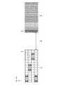
図2は一般構成例1におけるヒューズ領域116とその周縁の平面レイアウト図であり、図3は一般構成例1におけるヒューズ領域116とその周縁の断面図である。図3は、図2のA−Aで示す線に沿った半導体記憶装置100の断面を示している。また、図4は、一般構成例1におけるヒューズ領域116とガードリング118の周辺拡大図である。図2、3、4を参照しつつ一般構成例1について説明する。[General configuration example 1]
2 is a plan layout view of the
ヒューズ領域116には、レーザービームの照射により切断可能な複数のヒューズ素子120がxy平面方向に配列される(図2参照)。ヒューズ素子120とヒューズ素子120の間隔は、レーザービームの精度に依存する。 In the
ヒューズ素子120の上部はシリコン酸化膜122で被膜され、更に、その上部はパッシベーション膜124(保護膜)で被膜される(図3参照)。パッシベーション膜124は、ヒューズ素子120の直上部が開口するように形成される。これは、レーザービームLBを照射するとき、レーザービームLBのエネルギーがパッシベーション膜124によって減衰されないようにするためである。パッシベーション膜124はシリコン酸化膜122への堆積により形成されるため、開口部126の側面はz軸方向に対して斜形となる(図3参照)。いいかえれば、下層側(ヒューズ素子120側)よりも上層側の方が開口が大きくなる。xy平面においては、開口部126は長方形となる(図2参照)。 The upper portion of the
パッシベーション膜124はガードリング118を覆う(図3参照)。ガードリング118は、開口部126を包囲するように形成される(図2、図3参照)。図3に示すガードリング118は、第1層128、第2層130、第3層132という3つの層から成る。これらの層は、配線層であってもよい。第1層128、第2層130、第3層132には、それぞれ第1リング134、第2リング136、第3リング138が形成される。これらのリングは信号伝送のための配線である必要はない。 The
第1リング134と第2リング136は第1接続リング142により接続され、第2リング136と第3リング138は第2接続リング144に接続される。すなわち、図3のガードリング118は、第1リング134、第2リング136、第3リング138とそれらを接続する第1接続リング142、第2接続リング144が一体化したリングである。このような3層構成のガードリング118がヒューズ領域116を包囲している。また、これら3層のリングはz軸方向に直列している(図3参照)。 The
ヒューズ素子120は、第1リング134と同じ第1層128に形成される。ヒューズ素子120はVIA148を介してセル配線層150と接続され、セル配線層150はVIA152を介して更に下層の拡散層154に接続される。セル配線層150は、図示しない信号線を介して、ガードリング118よりも外側(図3の場合、y軸正方向側)に位置する救済回路(図示せず)等と接続される。 The
開口部126からレーザービームLBをヒューズ素子120に照射すると、レーザービームLBはシリコン酸化膜122を貫通し、ヒューズ素子120を溶断する。開口部126を包囲するガードリング118により、ガードリング118よりも外側に位置する救済回路等の各種電子回路はこの破壊によるストレスから守られる。また、開口部126から水や埃などの異物が進入した場合にも、ガードリング118により外側の電子回路や配線は守られる。いわば、ガードリング118は、電子回路領域を守るための防護壁である。 When the
図2〜図4に示す構成において、ガードリング118の底部、すなわち、第1リング134から、ヒューズ素子120までの距離をD1とする。第1層128においては、第1リング134の外側に各種配線(第1配線156)を配置するための第1配線領域158が確保される。ガードリング118よりも内側(図3のy軸負方向側:開口部126側)は、ガードリング118による防護ができないため、第1配線156を配置できない。このガードリング118よりも内側の領域を非配線領域160とよぶことにする。本発明者は、図2〜図4に示す構成では、距離D1が大きいため、非配線領域160が大きくなり、結果として、回路スペースを有効利用できないと考えた。 2 to 4, the distance from the bottom of the
[第1実施形態]
図5は第1実施形態におけるヒューズ領域116とその周縁の平面レイアウト図であり、図6は第1実施形態におけるヒューズ領域116とその周縁の断面図である。図6は、図5のA−Aで示す線に沿った半導体記憶装置100の断面を示している。また、図7は、第1実施形態におけるヒューズ領域116とガードリング118の周辺拡大図である。図5、6、7を参照しつつ第1実施形態について説明する。[First Embodiment]
FIG. 5 is a plan layout view of the
図6に示すように、第1実施形態においては第2リング136が内側(y軸負方向側:開口部126側)に延伸している。そして、第2リング136の内側において第1リング134が接続される。この結果、第1接続リング142と第2接続リング144は、z軸方向に直列していない。いいかえれば、第1リング134、第2リング136、第3リング138、第1接続リング142、第2接続リング144は、z軸方向に直列していない。第2リング136が内側にせり出す構造となっているため、第1リング134が開口部126に近づくことになり、距離D1が短縮されている。 As shown in FIG. 6, in the first embodiment, the
このように、第1リング134を第2リング136の内側に配置することにより非配線領域160が狭くなり、第1配線領域158を広く確保することができる。これは、第2リング136の下に第1リング134の非形成領域が確保されるため、ここに第1配線領域158を設けることができるためである。この広がった第1配線領域158を利用すれば、回路規模を拡大することなくより多くの配線が可能となる。また、第1配線領域158の拡大により、第1配線156をより太くできるので、配線抵抗を減らすこともできる。あるいは、電源幹線を新たに設けてもよい。このような対応策により、信号の伝搬速度を高速化しやすくなる。y軸方向だけでなく、x軸方向においても、第1実施形態における半導体記憶装置100は、一般構成例1よりも第1配線領域158を大きく確保しやすくなる。 As described above, by disposing the
次に、ガードリング118を4層で構成するときに一般的に考えられる構成を一般構成例2として説明し、そのあと、本発明を4層のガードリング118に応用した構成を第2実施形態として説明する。 Next, a configuration generally considered when the
[一般構成例2]
図8は、一般構成例2におけるヒューズ領域116とその周縁の断面図である。図8に示すガードリング118は、第1層128、第2層130、第3層132および第4層133の4層から構成される。第1層128、第2層130、第3層132、第4層133には、それぞれ第1リング134、第2リング136、第3リング138、第4リング140が形成される。パッシベーション膜124に充分な厚みがあれば4層以上の構成も可能である。[General configuration example 2]
FIG. 8 is a cross-sectional view of the
第1リング134と第2リング136は第1接続リング142により接続され、第2リング136と第3リング138は第2接続リング144に接続される。また、第3リング138と第4リング140は第3接続リング146により接続される。図8のガードリング118は、第1リング134、第2リング136、第3リング138、第4リング140とそれらを接続する第1接続リング142、第2接続リング144、第3接続リング146が一体化したものである。図8の場合、一般構成例1と同じくこれらのリングはz軸方向に直列している。 The
図8の場合、第2層130に設けられる第2配線領域に第2配線162が設置されている。第2リング136から開口部126までの距離をD2とする。ガードリング118よりも内側(図3のy軸負方向側)は、ガードリング118による防護ができないため、第1配線156や第2配線162を配置できない。この結果、一般構成例1と同じく、第1層128や第2層130において非配線領域160が大きくなりやすい。 In the case of FIG. 8, the
[第2実施形態]
図9は第2実施形態におけるヒューズ領域116とその周縁の断面図である。図9に示すように、第2実施形態においては第2リング136と第3リング138が開口部126側に延伸している。第2リング136の内側において第1リング134が接続され、第3リング138の内側において第2リング136が接続される。図9の場合、第1接続リング142と第2接続リング144、第3接続リング146は、z軸方向に直列していない。いいかえれば、第1リング134、第2リング136、第3リング138、第4リング140、第1接続リング142、第2接続リング144は、第3接続リング146z軸方向に直列していない。第3リング138と第2リング136が、内側にせり出す構造となっているため、距離D1、D2が短縮される。[Second Embodiment]
FIG. 9 is a cross-sectional view of the
このように、第1リング134を第2リング136の内側に、第2リング136を第3リング138の内側に配置することにより非配線領域160が狭くなるため、第1配線領域158や第2配線領域164を広く確保することができる。第2リング136の下に第1配線領域158(第1リング134の非形成領域)が確保されるとともに、第3リング138の下にも第2配線領域164(第2リング136の非形成領域)が広く確保されるためである。この広がった第1配線領域158と第2配線領域164により、省スペースにてより多くの配線が可能となる。また、第1配線領域158や第2配線領域164の拡大により、第1配線156や第2配線162をより太くできるので、配線抵抗を減らすこともできる。あるいは、電源幹線を新たに設けてもよい。このような対応策により、信号の伝搬速度を高速化しやすくなる。y軸方向だけでなく、x軸方向においても、第2実施形態における半導体記憶装置100は、一般構成例2よりも第1配線領域158や第2配線領域164を大きく確保しやすくなる。 As described above, the
最後に、ガードリング118を2層で構成するときに一般的に考えられる構成を一般構成例3として説明し、そのあと、本発明を2層のガードリング118に応用した構成を第3実施形態として説明する。 Finally, a configuration generally considered when the
[一般構成例3]
図10は、一般構成例3におけるヒューズ領域116とその周縁の断面図である。図10に示すガードリング118は、第1層128および第2層130という2つの層を含む。第1層128と第2層130には、それぞれ第1リング134と第2リング136が形成される。[General configuration example 3]
FIG. 10 is a cross-sectional view of the
第1リング134と第2リング136は第1接続リング142により接続される。図10のガードリング118は、第1リング134、第2リング136とそれらを接続する第1接続リング142が一体化したものである。図10の場合、一般構成例1、2と同じくこれらのリングはz軸方向に直列している。図10の場合においても、一般構成例1、2と同じく、第1層128において非配線領域160が大きくなりやすい。 The
[第3実施形態]
図11は第3実施形態におけるヒューズ領域116とその周縁の断面図である。図11に示すように、第3実施形態においては第2リング136が開口部126側に延伸している。第2リング136の内側において第1リング134が接続される。第2リング136が、一般構成例3と比べて内側にせり出す構造となっているため、距離D1が短縮される。[Third Embodiment]
FIG. 11 is a cross-sectional view of the
第1リング134を第2リング136の内側に配置することにより非配線領域160が狭くなるため、第1配線領域158を広く確保することができる。この広がった第1配線領域158により、省スペースにてより多くの配線が可能となる。y軸方向だけでなく、x軸方向においても、第3実施形態における半導体記憶装置100は、一般構成例3よりも第1配線領域158を大きく確保しやすくなる。 By disposing the
以上、実施形態に基づいて、半導体記憶装置100を説明した。パッシベーション膜124を、シリコン酸化膜122に堆積させるとき、開口部126の断面は図3等に示すように斜形になりやすい。このような構造に鑑みて、本実施形態に示したように第1リング134等を内側に寄せて配置すれば、第1配線領域158や第2配線領域164を開口部126のより近くまで確保できる。第1配線156や第2配線162等を省スペースにて多数配線しやすくなるため、ヒューズ素子120の実装密度を高めることができる。あるいは、第1配線156等の配線を太くしたり、電源幹線を増やすことにより、信号伝搬速度の低下を抑制することもできる。 The
以上、本発明をいくつかの実施の形態をもとに説明した。これらの実施の形態は例示であり、いろいろな変形および変更が本発明の特許請求範囲内で可能なこと、またそうした変形例および変更も本発明の特許請求の範囲にあることは当業者に理解されるところである。従って、本明細書での記述および図面は限定的ではなく例証的に扱われるべきものである。 The present invention has been described based on some embodiments. Those skilled in the art will understand that these embodiments are examples, and that various modifications and changes are possible within the scope of the claims of the present invention, and that such modifications and changes are also within the scope of the claims of the present invention. It is where it is done. Accordingly, the description and drawings herein are to be regarded as illustrative rather than restrictive.
100 半導体記憶装置、102 メモリバンク、104 ロウデコーダ、106 カラムデコーダ、108 ロウ制御回路、110 カラム制御回路、112 信号端子エリア、113 データ端子エリア、114 リードライトバッファ、116 ヒューズ領域、118 ガードリング、120 ヒューズ素子、122 シリコン酸化膜、124 パッシベーション膜、126 開口部、128 第1層、130 第2層、132 第3層、133 第4層、134 第1リング、136 第2リング、138 第3リング、140 第4リング、142 第1接続リング、144 第2接続リング、146 第3接続リング、148 VIA、150 セル配線層、152 VIA、154 拡散層、156 第1配線、158 第1配線領域、160 非配線領域、162 第2配線、164 第2配線領域。 100 semiconductor memory device, 102 memory bank, 104 row decoder, 106 column decoder, 108 row control circuit, 110 column control circuit, 112 signal terminal area, 113 data terminal area, 114 read / write buffer, 116 fuse area, 118 guard ring, 120 fuse element, 122 silicon oxide film, 124 passivation film, 126 opening, 128 first layer, 130 second layer, 132 third layer, 133 fourth layer, 134 first ring, 136 second ring, 138 third Ring, 140 Fourth ring, 142 First connection ring, 144 Second connection ring, 146 Third connection ring, 148 VIA, 150 Cell wiring layer, 152 VIA, 154 Diffusion layer, 156 First wiring, 158
Claims (8)
Translated fromJapanese前記ヒューズ領域の周囲に形成されるリングであって、第1層に形成される第1リングと前記第1層よりも上の第2層に形成される第2リングを含むガードリングと、を備え、
前記第2リングの下に前記第1リングの非形成領域が確保されるように、前記第1リングを前記第2リングの内側に配置したことを特徴とする半導体記憶装置。A fuse region in which fuse elements for storing addresses of defective memory cells are arranged; and
A ring formed around the fuse region, and a guard ring including a first ring formed in a first layer and a second ring formed in a second layer above the first layer; Prepared,
A semiconductor memory device, wherein the first ring is arranged inside the second ring so that a non-formation region of the first ring is secured under the second ring.
前記ガードリングは、前記保護膜内における前記開口部の周縁に設けられることを特徴とする請求項1に記載の半導体記憶装置。A protective film covering the first layer and the second layer and having an opening provided immediately above the fuse region;
The semiconductor memory device according to claim 1, wherein the guard ring is provided at a periphery of the opening in the protective film.
Priority Applications (2)
| Application Number | Priority Date | Filing Date | Title |
|---|---|---|---|
| JP2011095027AJP2012227421A (en) | 2011-04-21 | 2011-04-21 | Semiconductor storage device |
| US13/422,662US20120267749A1 (en) | 2011-04-21 | 2012-03-16 | Semiconductor device having fuse elements and guard ring surrounding the fuse elements |
Applications Claiming Priority (1)
| Application Number | Priority Date | Filing Date | Title |
|---|---|---|---|
| JP2011095027AJP2012227421A (en) | 2011-04-21 | 2011-04-21 | Semiconductor storage device |
Publications (1)
| Publication Number | Publication Date |
|---|---|
| JP2012227421Atrue JP2012227421A (en) | 2012-11-15 |
Family
ID=47020648
Family Applications (1)
| Application Number | Title | Priority Date | Filing Date |
|---|---|---|---|
| JP2011095027APendingJP2012227421A (en) | 2011-04-21 | 2011-04-21 | Semiconductor storage device |
Country Status (2)
| Country | Link |
|---|---|
| US (1) | US20120267749A1 (en) |
| JP (1) | JP2012227421A (en) |
Families Citing this family (1)
| Publication number | Priority date | Publication date | Assignee | Title |
|---|---|---|---|---|
| CN112216615B (en)* | 2019-07-09 | 2023-09-22 | 澜起科技股份有限公司 | Substrate packaging method capable of adjusting signal transmission time and structure thereof |
Citations (4)
| Publication number | Priority date | Publication date | Assignee | Title |
|---|---|---|---|---|
| JPH0969571A (en)* | 1995-08-31 | 1997-03-11 | Seiko Epson Corp | Semiconductor device and manufacturing method thereof |
| JP2000124412A (en)* | 1998-10-20 | 2000-04-28 | Nec Corp | Semiconductor integrated circuit |
| WO2004013909A1 (en)* | 2002-08-02 | 2004-02-12 | Hitachi, Ltd. | Semiconductor integrated circuit incorporating memory |
| JP2007165387A (en)* | 2005-12-09 | 2007-06-28 | Renesas Technology Corp | Semiconductor device, and method of manufacturing same |
Family Cites Families (23)
| Publication number | Priority date | Publication date | Assignee | Title |
|---|---|---|---|---|
| US6137155A (en)* | 1997-12-31 | 2000-10-24 | Intel Corporation | Planar guard ring |
| US6365958B1 (en)* | 1998-02-06 | 2002-04-02 | Texas Instruments Incorporated | Sacrificial structures for arresting insulator cracks in semiconductor devices |
| US6444544B1 (en)* | 2000-08-01 | 2002-09-03 | Taiwan Semiconductor Manufacturing Company | Method of forming an aluminum protection guard structure for a copper metal structure |
| JP3977578B2 (en)* | 2000-09-14 | 2007-09-19 | 株式会社東芝 | Semiconductor device and manufacturing method |
| JP2003086687A (en)* | 2001-09-13 | 2003-03-20 | Seiko Epson Corp | Semiconductor device |
| JP2004153015A (en)* | 2002-10-30 | 2004-05-27 | Fujitsu Ltd | Semiconductor device and manufacturing method thereof |
| JP3778445B2 (en)* | 2003-03-27 | 2006-05-24 | 富士通株式会社 | Semiconductor device |
| KR100534096B1 (en)* | 2003-06-24 | 2005-12-06 | 삼성전자주식회사 | Fuse region of a semiconductor memory device and method of fabricating the same |
| US6867441B1 (en)* | 2003-10-08 | 2005-03-15 | Taiwan Semiconductor Manufacturing Co., Ltd. | Metal fuse structure for saving layout area |
| US7009222B2 (en)* | 2004-04-22 | 2006-03-07 | Taiwan Semiconductor Manufacturing Co., Ltd | Protective metal structure and method to protect low-K dielectric layer during fuse blow process |
| US7538433B2 (en)* | 2005-06-16 | 2009-05-26 | Panasonic Corporation | Semiconductor device |
| JP4830455B2 (en)* | 2005-11-10 | 2011-12-07 | ルネサスエレクトロニクス株式会社 | Semiconductor device |
| US7397106B2 (en)* | 2005-12-12 | 2008-07-08 | Taiwan Semiconductor Manufacturing Company, Ltd. | Laser fuse with efficient heat dissipation |
| KR100745910B1 (en)* | 2006-01-23 | 2007-08-02 | 주식회사 하이닉스반도체 | Fuse Formation Method of Semiconductor Device |
| JP5175066B2 (en)* | 2006-09-15 | 2013-04-03 | ルネサスエレクトロニクス株式会社 | Semiconductor device |
| KR100819551B1 (en)* | 2006-10-20 | 2008-04-07 | 삼성전자주식회사 | Semiconductor device having a moisture barrier and manufacturing method thereof |
| US7964934B1 (en)* | 2007-05-22 | 2011-06-21 | National Semiconductor Corporation | Fuse target and method of forming the fuse target in a copper process flow |
| KR100967037B1 (en)* | 2007-10-17 | 2010-06-29 | 주식회사 하이닉스반도체 | Fuse box and its formation method |
| KR101576036B1 (en)* | 2009-05-06 | 2015-12-21 | 삼성전자주식회사 | Semiconductor device and manufacturing method thereof |
| KR101119805B1 (en)* | 2009-06-30 | 2012-03-21 | 주식회사 하이닉스반도체 | Fuse structure and fabrication method thereof |
| US8124448B2 (en)* | 2009-09-18 | 2012-02-28 | Advanced Micro Devices, Inc. | Semiconductor chip with crack deflection structure |
| US20120007211A1 (en)* | 2010-07-06 | 2012-01-12 | Aleksandar Aleksov | In-street die-to-die interconnects |
| US9059191B2 (en)* | 2011-10-19 | 2015-06-16 | International Business Machines Corporation | Chamfered corner crackstop for an integrated circuit chip |
- 2011
- 2011-04-21JPJP2011095027Apatent/JP2012227421A/enactivePending
- 2012
- 2012-03-16USUS13/422,662patent/US20120267749A1/ennot_activeAbandoned
Patent Citations (4)
| Publication number | Priority date | Publication date | Assignee | Title |
|---|---|---|---|---|
| JPH0969571A (en)* | 1995-08-31 | 1997-03-11 | Seiko Epson Corp | Semiconductor device and manufacturing method thereof |
| JP2000124412A (en)* | 1998-10-20 | 2000-04-28 | Nec Corp | Semiconductor integrated circuit |
| WO2004013909A1 (en)* | 2002-08-02 | 2004-02-12 | Hitachi, Ltd. | Semiconductor integrated circuit incorporating memory |
| JP2007165387A (en)* | 2005-12-09 | 2007-06-28 | Renesas Technology Corp | Semiconductor device, and method of manufacturing same |
Also Published As
| Publication number | Publication date |
|---|---|
| US20120267749A1 (en) | 2012-10-25 |
Similar Documents
| Publication | Publication Date | Title |
|---|---|---|
| JP5513730B2 (en) | Semiconductor memory device | |
| KR101156172B1 (en) | Semiconductor integrated circuit device | |
| JP5642567B2 (en) | Semiconductor device and manufacturing method thereof | |
| US6094382A (en) | Integrated circuit memory devices with improved layout of fuse boxes and buses | |
| JPH1040682A (en) | Semiconductor storage device | |
| US9275686B2 (en) | Memory banks with shared input/output circuitry | |
| US7835206B2 (en) | Semiconductor memory device capable of relieving defective bits found after packaging | |
| US6378118B1 (en) | Semiconductor integrated circuit having a MPU and a DRAM cache memory | |
| JP2011060909A (en) | Semiconductor memory device | |
| US10522235B2 (en) | Repair fuse latches using static random access memory array | |
| US6172929B1 (en) | Integrated circuit having aligned fuses and methods for forming and programming the fuses | |
| JP2012227421A (en) | Semiconductor storage device | |
| US11152037B2 (en) | Semiconductor memory device | |
| JP4524636B2 (en) | Semiconductor memory device | |
| US6650577B2 (en) | Integrated semiconductor memory having memory cells in a plurality of memory cell arrays and method for repairing such a memory | |
| US8593894B2 (en) | Semiconductor memory device having fuse elements programmed by irradiation with laser beam | |
| JP3164083B2 (en) | Semiconductor integrated circuit | |
| US20030128615A1 (en) | Integrated circuit having aligned fuses and methods for forming and programming the fuses | |
| US7324396B2 (en) | Sense amplifier organization for twin cell memory devices | |
| JPH1117019A (en) | Semiconductor integrated circuit device and method of manufacturing wiring program element used therein | |
| JP2012108988A (en) | Semiconductor storage device | |
| US8422321B2 (en) | Semiconductor memory device having regular area and spare area | |
| JP3836315B2 (en) | Semiconductor memory integrated circuit | |
| KR100646978B1 (en) | Bit Line Precharge Voltage Control Circuit of Semiconductor Memory Device | |
| JPH1125687A (en) | Semiconductor storage device |
Legal Events
| Date | Code | Title | Description |
|---|---|---|---|
| A711 | Notification of change in applicant | Free format text:JAPANESE INTERMEDIATE CODE: A711 Effective date:20130730 | |
| A521 | Request for written amendment filed | Free format text:JAPANESE INTERMEDIATE CODE: A523 Effective date:20130822 | |
| A621 | Written request for application examination | Free format text:JAPANESE INTERMEDIATE CODE: A621 Effective date:20140402 | |
| A977 | Report on retrieval | Free format text:JAPANESE INTERMEDIATE CODE: A971007 Effective date:20150123 | |
| A131 | Notification of reasons for refusal | Free format text:JAPANESE INTERMEDIATE CODE: A131 Effective date:20150127 | |
| A521 | Request for written amendment filed | Free format text:JAPANESE INTERMEDIATE CODE: A523 Effective date:20150421 | |
| A131 | Notification of reasons for refusal | Free format text:JAPANESE INTERMEDIATE CODE: A131 Effective date:20150707 | |
| A601 | Written request for extension of time | Free format text:JAPANESE INTERMEDIATE CODE: A601 Effective date:20150928 | |
| A02 | Decision of refusal | Free format text:JAPANESE INTERMEDIATE CODE: A02 Effective date:20160405 |