JP2012223585A - Electrosurgical apparatus with improved incision - Google Patents
Electrosurgical apparatus with improved incisionDownload PDFInfo
- Publication number
- JP2012223585A JP2012223585AJP2012097230AJP2012097230AJP2012223585AJP 2012223585 AJP2012223585 AJP 2012223585AJP 2012097230 AJP2012097230 AJP 2012097230AJP 2012097230 AJP2012097230 AJP 2012097230AJP 2012223585 AJP2012223585 AJP 2012223585A
- Authority
- JP
- Japan
- Prior art keywords
- generator
- operation mode
- cutting operation
- cutting
- mode
- Prior art date
- Legal status (The legal status is an assumption and is not a legal conclusion. Google has not performed a legal analysis and makes no representation as to the accuracy of the status listed.)
- Granted
Links
- 238000005520cutting processMethods0.000claimsabstractdescription78
- 238000000034methodMethods0.000claimsdescription12
- 239000007788liquidSubstances0.000claimsdescription8
- 238000001514detection methodMethods0.000claimsdescription4
- 238000001704evaporationMethods0.000claimsdescription4
- 230000008020evaporationEffects0.000claimsdescription3
- 230000003252repetitive effectEffects0.000claims1
- 230000007704transitionEffects0.000abstractdescription6
- 238000002485combustion reactionMethods0.000abstract1
- 239000012071phaseSubstances0.000description13
- 230000000694effectsEffects0.000description11
- FAPWRFPIFSIZLT-UHFFFAOYSA-MSodium chlorideChemical compound[Na+].[Cl-]FAPWRFPIFSIZLT-UHFFFAOYSA-M0.000description6
- 239000003990capacitorSubstances0.000description6
- 230000008859changeEffects0.000description5
- 230000000737periodic effectEffects0.000description5
- 238000001228spectrumMethods0.000description5
- 238000002679ablationMethods0.000description4
- 230000008878couplingEffects0.000description3
- 238000010168coupling processMethods0.000description3
- 238000005859coupling reactionMethods0.000description3
- 230000007423decreaseEffects0.000description3
- 238000002224dissectionMethods0.000description3
- 239000011780sodium chlorideSubstances0.000description3
- XLYOFNOQVPJJNP-UHFFFAOYSA-NwaterSubstancesOXLYOFNOQVPJJNP-UHFFFAOYSA-N0.000description3
- 230000005540biological transmissionEffects0.000description2
- 230000001419dependent effectEffects0.000description2
- 230000005284excitationEffects0.000description2
- 230000010355oscillationEffects0.000description2
- 230000008569processEffects0.000description2
- 230000009467reductionEffects0.000description2
- 239000000243solutionSubstances0.000description2
- 230000003595spectral effectEffects0.000description2
- 230000001052transient effectEffects0.000description2
- 230000008033biological extinctionEffects0.000description1
- 239000004020conductorSubstances0.000description1
- 238000010586diagramMethods0.000description1
- 239000012777electrically insulating materialSubstances0.000description1
- 230000005669field effectEffects0.000description1
- 239000012530fluidSubstances0.000description1
- 150000002500ionsChemical class0.000description1
- 229910052751metalInorganic materials0.000description1
- 239000002184metalSubstances0.000description1
- 238000012544monitoring processMethods0.000description1
- 238000013021overheatingMethods0.000description1
- 239000002504physiological saline solutionSubstances0.000description1
- 230000001105regulatory effectEffects0.000description1
- 230000003685thermal hair damageEffects0.000description1
- 239000012808vapor phaseSubstances0.000description1
Images


Classifications
- A—HUMAN NECESSITIES
- A61—MEDICAL OR VETERINARY SCIENCE; HYGIENE
- A61B—DIAGNOSIS; SURGERY; IDENTIFICATION
- A61B18/00—Surgical instruments, devices or methods for transferring non-mechanical forms of energy to or from the body
- A61B18/04—Surgical instruments, devices or methods for transferring non-mechanical forms of energy to or from the body by heating
- A61B18/12—Surgical instruments, devices or methods for transferring non-mechanical forms of energy to or from the body by heating by passing a current through the tissue to be heated, e.g. high-frequency current
- A61B18/1206—Generators therefor
- A61B18/1233—Generators therefor with circuits for assuring patient safety
- A—HUMAN NECESSITIES
- A61—MEDICAL OR VETERINARY SCIENCE; HYGIENE
- A61B—DIAGNOSIS; SURGERY; IDENTIFICATION
- A61B18/00—Surgical instruments, devices or methods for transferring non-mechanical forms of energy to or from the body
- A61B18/04—Surgical instruments, devices or methods for transferring non-mechanical forms of energy to or from the body by heating
- A61B18/042—Surgical instruments, devices or methods for transferring non-mechanical forms of energy to or from the body by heating using additional gas becoming plasma
- A—HUMAN NECESSITIES
- A61—MEDICAL OR VETERINARY SCIENCE; HYGIENE
- A61B—DIAGNOSIS; SURGERY; IDENTIFICATION
- A61B18/00—Surgical instruments, devices or methods for transferring non-mechanical forms of energy to or from the body
- A61B2018/00571—Surgical instruments, devices or methods for transferring non-mechanical forms of energy to or from the body for achieving a particular surgical effect
- A61B2018/00601—Cutting
- A—HUMAN NECESSITIES
- A61—MEDICAL OR VETERINARY SCIENCE; HYGIENE
- A61B—DIAGNOSIS; SURGERY; IDENTIFICATION
- A61B18/00—Surgical instruments, devices or methods for transferring non-mechanical forms of energy to or from the body
- A61B2018/00636—Sensing and controlling the application of energy
- A61B2018/00696—Controlled or regulated parameters
- A61B2018/00767—Voltage
- A—HUMAN NECESSITIES
- A61—MEDICAL OR VETERINARY SCIENCE; HYGIENE
- A61B—DIAGNOSIS; SURGERY; IDENTIFICATION
- A61B18/00—Surgical instruments, devices or methods for transferring non-mechanical forms of energy to or from the body
- A61B2018/00636—Sensing and controlling the application of energy
- A61B2018/00773—Sensed parameters
- A61B2018/00827—Current
- A—HUMAN NECESSITIES
- A61—MEDICAL OR VETERINARY SCIENCE; HYGIENE
- A61B—DIAGNOSIS; SURGERY; IDENTIFICATION
- A61B18/00—Surgical instruments, devices or methods for transferring non-mechanical forms of energy to or from the body
- A61B2018/00636—Sensing and controlling the application of energy
- A61B2018/00773—Sensed parameters
- A61B2018/00845—Frequency
- A61B2018/00857—Frequency harmonic
- A—HUMAN NECESSITIES
- A61—MEDICAL OR VETERINARY SCIENCE; HYGIENE
- A61B—DIAGNOSIS; SURGERY; IDENTIFICATION
- A61B18/00—Surgical instruments, devices or methods for transferring non-mechanical forms of energy to or from the body
- A61B2018/00636—Sensing and controlling the application of energy
- A61B2018/00773—Sensed parameters
- A61B2018/00875—Resistance or impedance
- A—HUMAN NECESSITIES
- A61—MEDICAL OR VETERINARY SCIENCE; HYGIENE
- A61B—DIAGNOSIS; SURGERY; IDENTIFICATION
- A61B18/00—Surgical instruments, devices or methods for transferring non-mechanical forms of energy to or from the body
- A61B18/04—Surgical instruments, devices or methods for transferring non-mechanical forms of energy to or from the body by heating
- A61B18/12—Surgical instruments, devices or methods for transferring non-mechanical forms of energy to or from the body by heating by passing a current through the tissue to be heated, e.g. high-frequency current
- A61B18/1206—Generators therefor
- A61B2018/1213—Generators therefor creating an arc
Landscapes
- Health & Medical Sciences (AREA)
- Surgery (AREA)
- Engineering & Computer Science (AREA)
- Life Sciences & Earth Sciences (AREA)
- Biomedical Technology (AREA)
- Otolaryngology (AREA)
- Nuclear Medicine, Radiotherapy & Molecular Imaging (AREA)
- Plasma & Fusion (AREA)
- Physics & Mathematics (AREA)
- Heart & Thoracic Surgery (AREA)
- Medical Informatics (AREA)
- Molecular Biology (AREA)
- Animal Behavior & Ethology (AREA)
- General Health & Medical Sciences (AREA)
- Public Health (AREA)
- Veterinary Medicine (AREA)
- Surgical Instruments (AREA)
Abstract
Translated fromJapaneseDescription
Translated fromJapanese本発明は、特に、外科器具に電力を供給するための装置を含む、電気外科装置に関する。 In particular, the present invention relates to an electrosurgical device including a device for supplying power to a surgical instrument.
電気外科装置またはシステムは、かなり長い間にわたって使用されている。例えば、特許文献1には、HF(高周波)電力を使用した電気外科器具を提供する、外科器具および装置を組み込んだ、電気外科システムが開示されている。対応するHF電圧を伝送するHF発電機が、この目的のために使用される。発電機は、電極において変換される電力を調整するために、間断なくオンおよびオフに切り換えられ、ここで、電力調整は、デューティサイクルを設定することにより可能である。これは、特に、電極のオーバーヒートを防止することを意図したものである。 Electrosurgical devices or systems have been in use for quite some time. For example, U.S. Patent No. 6,057,051 discloses an electrosurgical system incorporating a surgical instrument and apparatus that provides an electrosurgical instrument using HF (high frequency) power. An HF generator that transmits the corresponding HF voltage is used for this purpose. The generator is switched on and off without interruption to adjust the power converted at the electrodes, where power adjustment is possible by setting the duty cycle. This is particularly intended to prevent electrode overheating.
電極の温度を判定するために、電極における電圧を、DC(直流)成分について調べることが提案されており、これにより、電極が熱くなりすぎた場合、熱電子効果、すなわち、温度に依存した電子放出が検出され得る。接続されたプロセッサは、これを実現し、所望の電力低減をもたらすために、HF電圧のデューティサイクルを調整する。ここでの意図は、電極の損傷を回避することである。 In order to determine the temperature of the electrode, it has been proposed to examine the voltage at the electrode with respect to the DC (direct current) component, so that if the electrode becomes too hot, the thermionic effect, ie the temperature dependent electron. Release can be detected. The connected processor achieves this and adjusts the duty cycle of the HF voltage to provide the desired power reduction. The intention here is to avoid damaging the electrodes.
電気外科装置の電極電流の波高率を監視して、電極が切開(incision)モードにあるか、切断(cutting)モードにあるかについて推論する方法が、例えば特許文献2から、更に知られている。切開モードでは、電極は、イオンを伝導することが可能な水(例えば、Nacl溶液)によって囲まれている。この水は、比較的高い電流を運ぶ。これは、電極における蒸気泡の発生をもたらし、この中で、次に、プラズマ放電が発生する可能性がある。これが発生すると、流れる電流の波高率は、大幅に変化する。波高率において発生する変化が認識され、装置の更なる制御のために評価される。 A method for monitoring the crest factor of the electrode current of an electrosurgical device and inferring whether the electrode is in an incision mode or a cutting mode is further known from, for example, US Pat. . In the dissection mode, the electrode is surrounded by water (eg, a NaCl solution) that can conduct ions. This water carries a relatively high current. This results in the generation of vapor bubbles at the electrode, in which a plasma discharge can then occur. When this occurs, the crest factor of the flowing current changes significantly. Changes occurring in the crest factor are recognized and evaluated for further control of the device.
特に、切開フェーズから、切断/切除(ablation)フェーズへの移行が、重要になりうるということが見出された。電極を囲んでいる水は、非常に急速に蒸発し、従って、切開フェーズにおいて必要とされ、実際に電極に供給される電力は、急速に減少しなければならない。これが起きない場合、発生するプラズマ放電において、過剰な電力が供給されており、望ましくない効果がもたらされる可能性がある。他方、蒸気泡およびプラズマ放電の確実な発生をもたらすための、高電力での動作が、切開フェーズにおいては必要である。 In particular, it has been found that the transition from the incision phase to the ablation / ablation phase can be important. The water surrounding the electrode evaporates very quickly, so the power required for the dissection phase and the power actually supplied to the electrode must be rapidly reduced. If this does not occur, excessive power is supplied in the generated plasma discharge, which can have undesirable effects. On the other hand, high power operation is necessary during the incision phase to provide reliable generation of vapor bubbles and plasma discharge.
ここから考えを進めて、本発明の目的は、電気外科装置が、切開モードから、切断モードに、安全かつ制御されたやり方で切り換わることを可能にする、概念を提供することである。 Proceeding from now, an object of the present invention is to provide a concept that allows an electrosurgical device to switch from an incision mode to a cutting mode in a safe and controlled manner.
この目的は、請求項1による電気外科装置、および/または、請求項9による方法を使用して達成される。 This object is achieved using an electrosurgical device according to claim 1 and / or a method according to claim 9.
本発明によれば、HF発電機が、HF電力を提供するために使用され、前記HF発電機は、電気外科器具の電極に接続され、または接続可能であり、かつ、その電力伝送は制御可能である。最も単純な場合、この目的のために、前記HF発電機は、オンおよびオフにされてもよい。 According to the present invention, an HF generator is used to provide HF power, said HF generator being connected to or connectable to an electrode of an electrosurgical instrument and its power transmission being controllable. It is. In the simplest case, for this purpose, the HF generator may be turned on and off.
HF発電機は、少なくとも1つの共振回路と、1つの増幅器モジュール(例えば、非線形増幅器モジュールとして使用される電子スイッチ)とを含む。電子スイッチは、共振回路を励起するために、正しい位相でオフおよびオンにされる。スイッチの、この周期的なスイッチオンおよびスイッチオフは、HF電力の生成を中断するために、中断される。スイッチオンおよびスイッチオフについての、デューティサイクルの選択は、HF電力に影響を及ぼすことが可能である。 The HF generator includes at least one resonant circuit and one amplifier module (eg, an electronic switch used as a non-linear amplifier module). The electronic switch is turned off and on with the correct phase to excite the resonant circuit. This periodic switch on and switch off of the switch is interrupted to interrupt the generation of HF power. Duty cycle selection for switch on and switch off can affect HF power.
本発明による装置は、センサ装置を含む。これは、切開フェーズの終了、およびHF放電の開始を認識する。この場合、装置は、HF発電機を、切開モードから、切断モードに切り換える。HF発電機は、切開フェーズでは、高電流伝送とともに動作させられる。切断モードでは、HF発電機は、より低い電流において動作する。 The device according to the invention comprises a sensor device. This recognizes the end of the incision phase and the start of HF discharge. In this case, the apparatus switches the HF generator from the cutting mode to the cutting mode. The HF generator is operated with high current transmission in the cutting phase. In disconnected mode, the HF generator operates at a lower current.
最も単純な実施形態では、切開モードと切断モードとの間の切り換えは、波高率、HF発電機によって生成されるHF電圧/生成されるHF電流、の変化によって達成される。波高率は、電圧または電流の実効値に対する、ピーク電圧または電流値の比である。 In the simplest embodiment, switching between incision mode and incision mode is achieved by a change in crest factor, HF voltage generated by HF generator / generated HF current. The crest factor is the ratio of the peak voltage or current value to the effective value of voltage or current.
切開の間、波高率は、好ましくは、1.0と2.5との間であり、好ましくは、1.4と2.5との間であり、切断/切除動作モードでは、2.5と5.0との間の波高率が使用される。好ましい実施形態では、波高率は、初期のHP放電が認識され次第、切開フェーズを目的としたより低い値から、切断モードを目的としたより高い値に、即座に切り換えられる。波高率のスライディング制御は、少なくともこの切り換え期間の間は実施されず、これにより、望ましくない外科的効果をもたらす可能性がある過渡応答が回避される。 During the incision, the crest factor is preferably between 1.0 and 2.5, preferably between 1.4 and 2.5, and 2.5 / 2.5 in the cutting / ablation mode of operation. A crest factor between 1 and 5.0 is used. In a preferred embodiment, the crest factor is immediately switched from a lower value for the cutting phase to a higher value for the cutting mode as soon as the initial HP discharge is recognized. The crest factor sliding control is not performed at least during this switching period, thereby avoiding transient responses that can lead to undesirable surgical effects.
切開および切断動作モードにおける波高率の大きさに関係なく、HF発電機が、切断モードにおいて、切開動作モードにおける波高率より大きな波高率を生成することは有利である。 Regardless of the crest factor magnitude in the cutting and cutting mode of operation, it is advantageous for the HF generator to generate a crest factor in the cutting mode that is greater than the crest factor in the cutting mode of operation.
波高率の切り換えによる、切開動作モードから切断動作モードへの、HF発電機の動作モードの制御された切り換えは、例えば、方形の変調曲線(これを使用して、HF発電機によって供給される振動が変調される)のデューティサイクルの突然の変化によって達成されてもよい。言い換えると、電力に影響を及ぼすために、HF発電機は、周期的にオンおよびオフに切り換えられる。切開動作モードでは、スイッチオン時間とサイクル時間との間の、高い割合が存在し、切断動作モードでは、スイッチオン時間とサイクル時間との間の、より低い割合が存在する。 The controlled switching of the operating mode of the HF generator from the cutting operation mode to the cutting operation mode by switching the crest factor is, for example, a square modulation curve (using this a vibration supplied by the HF generator). May be achieved by a sudden change in the duty cycle. In other words, the HF generator is periodically switched on and off to affect the power. In the cutting operation mode, there is a high ratio between the switch-on time and the cycle time, and in the cutting operation mode, there is a lower ratio between the switch-on time and the cycle time.
切開モードにおいて、生物組織内への高いエネルギー入力をもたらさない限り、1というデューティサイクル(すなわち、1.4という波高率(正弦))が使用されてもよい。HF発電機は、この場合、連続モードで動作する。しかし、生物組織内に導入される電力が制限されるように(例えば、400Ws/s)、切開動作モードにおいても、1未満のデューティサイクルが使用されることが好ましい。この場合、電力低減のために、HF電圧の短いブランキング間隔を使用することが可能である。その上、各HF振動サイクルの開始時に、HF発電機を再度オンに切り換えると、より高い電流パルスが電極において得られ、これは、プラズマ点火をサポートする。これは、並列共振回路がHF発電機として使用され、そのコイルが、HF振動サイクルの開始時に、全動作電圧に一時的に接続される場合、特に当てはまる。 In dissection mode, a duty cycle of 1 (ie, a crest factor of 1.4 (sine)) may be used as long as it does not provide high energy input into the biological tissue. In this case, the HF generator operates in a continuous mode. However, it is preferred that a duty cycle of less than 1 is also used in the incision mode of operation so that the power introduced into the biological tissue is limited (eg, 400 Ws / s). In this case, it is possible to use a blanking interval with a short HF voltage for power reduction. Moreover, when the HF generator is switched on again at the start of each HF oscillation cycle, a higher current pulse is obtained at the electrode, which supports plasma ignition. This is especially true if a parallel resonant circuit is used as the HF generator and its coils are temporarily connected to the full operating voltage at the beginning of the HF oscillation cycle.
HF発電機を提供するユニット(例えば、パワーパック)は、調整された、または調整されていない動作電圧を提供してもよい。しかし、一般に、HF発電機は、低い負荷抵抗において(すなわち、切開モードにおいて)、電極において有効な電圧の減少をもたらすことが可能な、(好ましくは正の)内部抵抗を有する。 A unit (eg, power pack) that provides an HF generator may provide a regulated or unregulated operating voltage. However, in general, HF generators have (preferably positive) internal resistance that can result in a decrease in the effective voltage at the electrode at low load resistance (ie, in cutting mode).
切開動作モードから切断動作モードへの移行の認識を可能にするために、電極に流れる電流、または、電極において印加される電圧が、監視されてもよい。電圧が監視される場合、電極における電圧の増加に基づいて、開始中の切開が検出されてもよい。切開モードでの、電極における実効オーム抵抗は、数十オーム近辺(例えば、25オーム)であるのに対して、切断モードでは、この抵抗は、それよりも著しく高い(例えば、200オームを超える)。 To allow recognition of the transition from the cutting mode to the cutting mode, the current flowing through the electrode or the voltage applied at the electrode may be monitored. When the voltage is monitored, a starting incision may be detected based on the increase in voltage at the electrode. The effective ohm resistance at the electrode in cutting mode is around tens of ohms (eg, 25 ohms), whereas in cutting mode, this resistance is significantly higher (eg, over 200 ohms). .
開始中のプラズマ放電を認識するために、電極に流れる電流を、または電極において印加される電圧を、スペクトル的に調べることも可能である。この目的のために役立つスペクトルアナライザが、切開フェーズにおいては存在しない調和波の突然の出現から、放電の開始を認識することが可能である。 In order to recognize the starting plasma discharge, it is also possible to spectrally examine the current flowing through the electrode or the voltage applied at the electrode. A spectrum analyzer useful for this purpose can recognize the onset of discharge from the sudden appearance of a harmonic wave that does not exist in the incision phase.
更に、電極電圧のDC成分を、開始中の放電の指標として使用することが可能である。このDC成分は、熱電子効果に基づくものではなく、主として電界効果(field effects)に基づくものであり、従って、比較的冷たい電極について、すでに見られる。例えば、少なくとも、好適な電極形状について、電極における、電界強度によって引き起こされる電子放出(field strength−induced electron emission)は、プラズマ放電に関して、対向電極を形成する組織の電子放出より大きい可能性がある。 Furthermore, the DC component of the electrode voltage can be used as an indicator of the starting discharge. This DC component is not based on the thermionic effect, but mainly on field effects and is therefore already seen for relatively cold electrodes. For example, at least for a suitable electrode shape, the field strength-induced electron emission at the electrode may be greater with respect to the plasma discharge than the electron emission of the tissue forming the counter electrode.
本発明の有利な実施形態の更なる詳細は、図面、および、実施形態の以下の説明から、あるいは、従属請求項から明白である。 Further details of advantageous embodiments of the invention are apparent from the drawings and the following description of the embodiments or from the dependent claims.
図1は、電気外科器具11と、この器具11を提供するための電気医療装置12とを有する、電気外科装置10/電気外科システムを示す。器具11は、例えば、外科医によってハンドル13により手作業で操作されることが可能な器具であり、好ましくは電気絶縁材料と電極14からなり、露出した金属導体を少なくとも1つの場所において有する。これは、例えば、球状、へら状、ブレード状、針状などの、任意の医療上望ましい形状を有してもよい。 FIG. 1 shows an
本実施形態では、電気外科器具は、少なくとも図1および図2において、単極器具として示されている。これは、給電ライン15を介して、装置12に接続される。単極の実施形態では、戻りラインとして働く更なるライン16が、例えば、外科的効果がもたらされるべき患者の、生物組織17を、装置12に接続する。ライン15および16は、この場合、別個のケーブル内に収容される。ライン16は、組織17へのガルバニック結合または容量結合を作ることが可能である。 In this embodiment, the electrosurgical instrument is shown as a monopolar instrument at least in FIGS. This is connected to the
図1および図2の描写では、器具11は、1つのみの電極14を有する単極器具である。しかし、これは、双極器具(その2つの電極は、ライン15、16によって給電される)であってもよい。この場合、ライン15、16は、共通のケーブル内に収容されることが好ましい。 In the depiction of FIGS. 1 and 2, the instrument 11 is a monopolar instrument having only one
装置12は、HF発電機18を含み、これは、本例示的実施形態では、(並列)共振回路19と、励起のために働く電子的要素20と、制御装置21とによって形成される。電子的要素20は、増幅器特性を示す。要素20は、線形または非線形設計のものであってもよい。好ましい実施形態では、これは、電子スイッチ22(例えば、MOSFET、IGBTなど)である。電子スイッチ22は、制御電極23を有し、これは、制御装置21に接続され、制御装置21によって制御信号を供給される。スイッチ22は、共振回路19と基準電位との間に、制御装置21の制御信号に従って開閉される電流経路24を形成する。共振回路19は、更に、動作電圧Ubに接続される。The
共振回路19は、並列に接続された、かつ、好ましくは、高い回路品質の共振回路を提供する、少なくとも1つのキャパシタCとコイルLとを含む。共振回路19の共振周波数は、例えば350kHzという、伝送されるHF電圧の周波数を決定する。キャパシタCの容量は、好ましくは、50nFと200nFとの間であり、コイルLのインダクタンスは、好ましくは、4μHと1μHとの間である。コイルLは、デカップリングコイルL1と磁気的に結合され、デカップリングコイルL1は、デカップリングキャパシタ25およびセンサ装置26を介して、ライン15、16に、そして、最終的に、電極14に接続される。 The
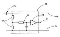
センサ装置26は、電極14におけるプラズマ放電の成長を検出するために使用される。これは、例えば、図5に示す形態のものであってもよい。その入力は、カップリングキャパシタ25を介して、デカップリングコイルL1に接続された、分圧器27である。ローパスフィルタ28が、平均電圧値を形成し、これは、増幅器29によって捕捉され、その出力30において、平均電圧値を特徴付ける信号として利用可能にされる。この信号は、制御装置21に供給され、制御装置21は、信号が閾値より大きいか、小さいかを判定し、それに応じて、切開動作モード、または切断/切除モードを制御する。比較器が、増幅器29の代わりに提供されてもよい。 The
比較器または制御装置の閾値は、切開フェーズの間存在する、低いDC成分と、切断モードの間、電極14において存在する、電圧の高いDC成分との間を、確実に区別することが可能なように指定されてもよい。従って、信号は、切開フェーズの間の第1の値と、第1の値とは異なる、切断フェーズの間の第2の値とを有する。これらの値に基づいて、制御装置21は、電極14の動作状態を検出する。 The threshold of the comparator or controller can reliably distinguish between the low DC component present during the cutting phase and the high voltage DC component present at the
装置12は、更に、動作電圧源を、この場合、制御されたパワーサプライ34の形態で有し、これは、HF発電機18、および全ての更なる構成要素に、動作電圧Ubを供給する。動作電圧Ubは、例えば、数百ボルト(例えば、400ボルト)という値を有する。動作電圧は、異なる外科的効果の選択のために、切り換え可能、または調節可能であってもよい。特に、制御装置21の構成要素、または更に操作要素によって、パワーサプライ34の電力調整、および/または、特性の設定が可能なように、制御装置21とパワーサプライ34との間に、効果経路(effect path)を提供することが可能である。The
制御装置21は、HF発電機18の動作を制御する、1つまたは複数の電子回路(特に、マイクロコントローラ)を含んでもよい。装置12の、以下に記載する機能は、特に、制御装置21内の任意のマイクロコントローラの、機能の、更にはまたプログラミングの、認識を可能にする。 The
機能の説明のために、図2に注目されたい。これは、液体31によって囲まれた、組織17内の電極14を示す。この液体は、場合によっては、組織液またはその他の液体と混合された、例えば、生理的食塩水である。例えば切開などの、外科的効果が、電極14によってもたらされるべきである場合、HF発電機18が作動させられる。これは、外科医によって操作される、例えば、スイッチ、またはその他の装置(図示せず)を使用して行われてもよい。この指示により、HF発電機18は、最初、切開動作モードで動作させられる。ここで、制御装置21は、共振回路19をその共振周波数まで励起するために、スイッチ22を迅速に閉じること、およびその後の、周期的、段階的な(periodic phased)、開閉をもたらす。HF電力は、共振回路19から、デカップリングコイルL1を介して引き出される。従って、高周波電流iが、電極14に供給される。電極14は、組織17と接触している。図3に示す、高周波電流iは、数アンペア(例えば、6〜8アンペア)の振幅で流れる。結果として生じる比較的高い電力入力は、電極の付近に存在する液体の突然の蒸発と、蒸気泡32の発生とをもたらす。電極14から組織17への境界抵抗の大きさは、このプロセスにおいて突然増加する。発生する蒸気泡32内で、HFガス放電が形成され、プラズマ33が生成される可能性がある。 For a functional description, note FIG. This shows the
抵抗の突然の増加の結果として、図3からわかるように、蒸気泡が形成される時点t1において、流れる電流iは、突然小さくなる。蒸気泡32における、そして、ライン15、16における、HF AC(交流)電圧は、電極14および組織17からの様々な電子放出に起因して、DC成分を即座に発達させる可能性がある。これは、センサ装置26によって検出される。出力30において現れる適切な信号が、制御装置21に到達し、切開モードIから、切断モードIIへの移行を特徴付ける。 As a result of the sudden increase in resistance, as can be seen from FIG. 3, at the instant t1 when the vapor bubble is formed, the flowing current i suddenly decreases. The HF AC (alternating current) voltage in
センサ装置26によって生成される信号は、液体の、気体または蒸気相への転移を、及びこれによる蒸気泡32の発生を、特徴付ける。この信号は、HF発電機18の動作を、切開動作モードから、切断動作モード(これは従って、t1より後の複数の時点に該当する)に切り換えるために、制御装置21によって使用される。これは、図3に示されている。電流iの値は減少し、期間0〜t1について、すなわち、切開動作モードについて有効な、第1の変調から開始される、高周波電流iの変調は、切開の後の時間、すなわち、切断動作モードの間、有効な第2の変調に切り換えられる。 The signal generated by the
第1の変調は、図3において、左下に示されている。図からわかるように、HF発電機18は、切開動作モードの間、わずかな中断を伴って、または、中断なしで動作する。その波高率は、従って、約1.4であるか、またはこれよりわずかに大きいが、好ましくは、しかし、少なくとも2.5未満である。HF発電機18が、連続モードではなく、図3の左下に示すように、パルス動作モードで動作している場合、デューティサイクルT1/Te1は、ほぼ1であり、好ましくは、少なくとも0.7〜0.8より大きい。T1は、ここでは、変調信号の周期であり、Te1は、スイッチング周期である。これは、全体として、1.4より少し大きい値を有する波高率をもたらす。 The first modulation is shown in the lower left in FIG. As can be seen, the
時間t1において、変調は、第1の動作モードから、第2の動作モードに切り換えられ、第2の動作モードでは、より大きな波高率が存在する。デューティサイクルT2/Te2は、好ましくは、0.7より著しく小さい。結果は、t1より後の時間の、図3の、第1の上部の図の、右半分による、間欠的なHF波列である。 At time t1, the modulation is switched from the first operation mode to the second operation mode, where a higher crest factor exists. The duty cycle T2 / Te2 is preferably significantly less than 0.7. The result is an intermittent HF wave train according to the right half of the first upper diagram of FIG. 3 at a time after t1.
蒸気泡32の発生が認識され次第、切開動作モードの低い波高率から、切断動作モードのためのより高い波高率に、即座に切り換えることによって、形成中の蒸気泡32内への過剰な電力の入力、および、組織17への、および/または、電極14への、熱損傷が、防止される。その上、変調の、従って、波高率の、突然の切り換えによって、低速の制御プロセスの影響と、時点t1の後の、例えばHF電圧の上昇などの、過渡事象の影響とが、回避される。 As soon as the generation of the
図4は、本発明のために使用可能な、更なる態様を示す。明らかなように、少なくとも好ましい実施形態では、HF発電機18の、短い周期的なブランキングが実行される。例えば、デューティサイクルT1/Te1は、0.9という値を有する。例えば、T1は、50msである。HF発電機18のHF電圧の2つの波列の間で約5ms続く休止において、HF電圧は安定する。再開のために、励起のために働くスイッチ22が、短期間閉じられる。スイッチ22を閉じたことの結果として、第1の電流ピーク35が生じ、これは、例えば最大10Apeakという、大きな値を取る可能性があり、従って、切開動作モードにおけるプラズマ33の点火性の実質的な増加をもたらす。この効果は、期間T1の持続時間、およびデューティサイクルTe1とは無関係に使用されることが可能である。このようにして、例えば、共振回路19の周期的な反復する過渡現象によって引き起こされる、周期的な電流ピークを有する、ほぼ連続的なHF波列が、切開動作モードの間の電流iについて得られる。FIG. 4 shows a further embodiment that can be used for the present invention. As is apparent, in at least the preferred embodiment, a short periodic blanking of the
本発明による、装置10の全ての実施形態では、蒸気泡32およびプラズマ33の発生の確実な認識が必要とされる。上述の、電極14におけるHF電圧のDC成分の検出の代替として、その他の特徴的な電気的変数が評価されてもよい。例えば、電極14におけるHF電圧は、HF発電機の内部抵抗の結果として、切開動作モードの間、切断モードの間より低い値を有する。センサ装置26は、閾値回路であってもよい。その出力信号は、HF電圧の値が、好適な指定された限界値より大きいか、小さいかを示す。出力信号は、次に、制御装置21に送信される。 In all embodiments of the
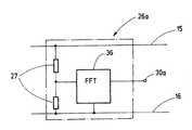
図6は、更なる代替のセンサ装置26aを示す。センサ装置26aは、ライン15、16の間のHF電圧のスペクトルを捕捉する、分圧器27に接続された周波数解析モジュール36を有する。印加電圧は、周波数解析モジュール36によって解析される。これは、例えば、ここではマイクロコントローラによって実行される、高速フーリエ変換によって実行されてもよい。周波数解析モジュール36は、次に、例えば、特徴的なスペクトル線またはスペクトル成分の存在について、スペクトルを評価し、スペクトルに基づいて、蒸気泡の成長が認識された場合、出力30aに信号を送信する。スペクトルの特徴的変化は、電極14から組織17への境界抵抗の、特性における変化の結果である。電極14が、組織17と、塩化ナトリウム溶液(NaCl)を介して接触している限り、境界抵抗は、ほぼ線形である。これはしかし、プラズマ33が点火するとすぐに、非常に実質的に非線形となり、その結果として、特徴的調和波(characteristic harmonic waves)が生成される。 FIG. 6 shows a further
センサ装置26、26aは、プラズマの認識に対する、切断モードの即座の開始のために使用される。しかし、センサ装置26、26aが、出力33における対応する信号の変化に基づいて、プラズマ33の消滅を認識した場合、制御装置21は、それに応じて反応して、装置12およびそのHF発電機18を、切開動作モードIに戻してもよい。従って、継続的に反復する消滅事象が発生しても、例えば、組織の切除を実行するための、周期的に反復する切開動作モードでの動作が可能である。これは、全てのタイプの記載されたセンサ装置に、および、全てのタイプの変調に当てはまる。 The
切開動作モードにおける、プラズマ33の点火から、切断動作の間の、プラズマ33の燃焼への、確実な移行を達成するために、電力を使用する器具11を提供するための電気医療装置12は、センサ装置26によって形成される点火認識手段を装備する。この点火認識手段は、点火が認識されるとすぐに、装置12内に存在するHF発電機18を、切開動作モードIから、切断動作モードIIに切り換える。切り換えは、好ましくは、切開動作モードにおける、2.5未満という低い波高率から、切断動作モードにおける、2.5を超える高い波高率への、HF変調の切り換えによってもたらされる。 An electro-
10 電気外科装置/システム
11 電気外科器具
12 電気医療装置
13 ハンドル
14 電極
15 給電ライン
16 戻りライン
17 組織
18 HF発電機
19 共振回路/並列共振回路
20 電子的要素
21 制御装置
22 スイッチ
23 制御電極
24 電流経路
Ub 動作電圧
C 共振回路19のキャパシタ
L 共振回路19のコイル
L1 デカップリングコイル
25 カップリングキャパシタ
26 センサ装置
26a センサ装置
27 分圧器
28 ローパスフィルタ
29 増幅器
30 出力
30a 出力
31 液体
32 蒸気泡
33 プラズマ
34 パワーサプライ、動作電圧源
35 電流ピーク
36 周波数解析モジュール
I 切開動作モード
II 切断動作モードDESCRIPTION OF
Claims (15)
Translated fromJapanese前記装置(12)は、
切開フェーズの間の、湿った組織環境内に配置された電極(14)が周囲の液体(31)を蒸発させる、切開動作モード(I)、および、切断フェーズの間の、前記電極(14)におけるHF(高周波)放電が維持される切断動作モード(II)における、HF電力を生成するための、制御可能なHF発電機(18)と、
発生した蒸発、および発生するHF放電を認識するための、センサ装置(26、26a)と、
を備え、
前記センサ装置(26、26a)は、前記開始中のHF放電を検出すると、前記HF発電機(18)を、切開動作モード(I)から、切断動作モード(II)に切り換える、
電気外科装置(10)。An electrosurgical device (10) having a device (12) for supplying power to an instrument (11),
The device (12)
During the cutting phase, the electrode (14) placed in the moist tissue environment evaporates the surrounding liquid (31), and the electrode (14) during the cutting operation mode (I) and during the cutting phase A controllable HF generator (18) for generating HF power in a cutting operation mode (II) in which HF (high frequency) discharge is maintained in
A sensor device (26, 26a) for recognizing the generated evaporation and the generated HF discharge;
With
When the sensor device (26, 26a) detects the starting HF discharge, the HF generator (18) is switched from the cutting operation mode (I) to the cutting operation mode (II).
Electrosurgical device (10).
共振回路(19)と、
前記共振回路(19)に全動作電圧を繰り返し印加するための、前記共振回路(19)に接続された、スイッチング動作で動作する電子スイッチ(22)と、
を有することを特徴とする、
請求項5に記載の電気外科装置。The HF generator (18)
A resonant circuit (19);
An electronic switch (22) operating in a switching operation, connected to the resonant circuit (19), for repeatedly applying a full operating voltage to the resonant circuit (19);
It is characterized by having
The electrosurgical device according to claim 5.
前記装置(12)は、
制御可能なHF発電機(18)を含み、
該HF発電機(18)は、切開動作モードにおける切開フェーズ(I)の間、HF電力を生成することにより、接続された外科器具(11)の、湿った組織環境内に置かれている電極(14)を囲む液体(31)を蒸発させ、
前記HF発電機(18)は、切断動作モードにおいて、前記電極(14)におけるHF放電を、切断フェーズ(II)の間維持し、
前記HF発電機(18)は、センサ装置(26、26a)によって、発生した蒸発、およびHF放電の発生が認識され次第、前記切開動作モード(I)から、前記切断動作モード(II)に切り換えられる、
方法。A method of operating an electrosurgical device (10) and a device (12) for supplying power to an instrument (11) comprising:
The device (12)
Including a controllable HF generator (18),
The HF generator (18) is an electrode placed in the moist tissue environment of the connected surgical instrument (11) by generating HF power during the cutting phase (I) in the cutting mode of operation. Evaporating the liquid (31) surrounding (14);
The HF generator (18) maintains a HF discharge at the electrode (14) during a cutting phase (II) in a cutting operation mode;
The HF generator (18) switches from the cutting operation mode (I) to the cutting operation mode (II) as soon as the sensor device (26, 26a) recognizes the generated evaporation and the generation of HF discharge. Be
Method.
共振回路(19)と、
スイッチングモードで動作し、前記共振回路(19)に接続された、電子スイッチ(22)と、
を有し、
前記電子スイッチ(22)は、前記共振回路(19)を、全動作電圧(Ub)に繰り返し接続することを特徴とする、
請求項9に記載の方法。The HF generator (18)
A resonant circuit (19);
An electronic switch (22) operating in switching mode and connected to the resonant circuit (19);
Have
The electronic switch (22) is characterized in that the resonant circuit (19) is repeatedly connected to the total operating voltage (Ub ),
The method of claim 9.
Applications Claiming Priority (2)
| Application Number | Priority Date | Filing Date | Title |
|---|---|---|---|
| EP11163501.7AEP2514380B1 (en) | 2011-04-21 | 2011-04-21 | Electrical surgical device with improved cutting |
| EP11163501.7 | 2011-04-21 |
Publications (2)
| Publication Number | Publication Date |
|---|---|
| JP2012223585Atrue JP2012223585A (en) | 2012-11-15 |
| JP5680013B2 JP5680013B2 (en) | 2015-03-04 |
Family
ID=44117580
Family Applications (1)
| Application Number | Title | Priority Date | Filing Date |
|---|---|---|---|
| JP2012097230AActiveJP5680013B2 (en) | 2011-04-21 | 2012-04-23 | Electrosurgical device to improve incision |
Country Status (5)
| Country | Link |
|---|---|
| US (1) | US9980768B2 (en) |
| EP (1) | EP2514380B1 (en) |
| JP (1) | JP5680013B2 (en) |
| CN (1) | CN102772247B (en) |
| PL (1) | PL2514380T3 (en) |
Cited By (10)
| Publication number | Priority date | Publication date | Assignee | Title |
|---|---|---|---|---|
| JP2015083128A (en)* | 2013-10-21 | 2015-04-30 | エルベ エレクトロメディジン ゲーエムベーハーErbe Elektromedizin GmbH | Instrument test arrangement |
| JP2015529503A (en)* | 2012-08-22 | 2015-10-08 | オリンパス・ウィンター・アンド・イベ・ゲゼルシャフト・ミット・ベシュレンクテル・ハフツング | High frequency surgical equipment |
| JP2018503421A (en)* | 2014-12-10 | 2018-02-08 | オリンパス・ウィンター・アンド・イベ・ゲゼルシャフト・ミット・ベシュレンクテル・ハフツング | Electrosurgical generator, and control apparatus and method |
| WO2018229891A1 (en)* | 2017-06-14 | 2018-12-20 | オリンパス株式会社 | Control device |
| JP2019034158A (en)* | 2012-09-11 | 2019-03-07 | ヘッカーマン, ブラッドHECKERMAN, Brad | Electric discharge washer and method |
| JP2019198641A (en)* | 2018-05-14 | 2019-11-21 | エルベ エレクトロメディジン ゲーエムベーハーErbe Elektromedizin GmbH | Apparatus and method for generating plasma in aqueous environment |
| KR20200068592A (en)* | 2018-12-05 | 2020-06-15 | 에에르베에 엘렉트로메디찐 게엠베하 | Plasma treatment device |
| JP2021510830A (en)* | 2018-03-13 | 2021-04-30 | オリンパス・ウィンター・アンド・イベ・ゲゼルシャフト・ミット・ベシュレンクテル・ハフツング | Test equipment for electrosurgery generators |
| JP2022135935A (en)* | 2021-03-03 | 2022-09-15 | オリンパスメディカルシステムズ株式会社 | METHOD OF OPERATION OF MEDICAL DEVICE AND CONTROLLER |
| JP2023033229A (en)* | 2021-08-26 | 2023-03-09 | オリンパス・ヴィンター・ウント・イベ・ゲゼルシャフト・ミット・ベシュレンクテル・ハフツング | Electrosurgical generator with hf high voltage multilevel inverter |
Families Citing this family (4)
| Publication number | Priority date | Publication date | Assignee | Title |
|---|---|---|---|---|
| PL2815695T3 (en) | 2013-06-20 | 2019-10-31 | Erbe Elektromedizin | Surgical instrument with tissue detection |
| US11045247B2 (en) | 2018-02-20 | 2021-06-29 | Covidien Lp | Systems and methods for controlling arcing |
| US11696795B2 (en)* | 2018-07-13 | 2023-07-11 | Medtronic Advanced Energy Llc | Amplitude modulated waveform circuitry for electrosurgical devices and systems, and related methods |
| DE102021122284A1 (en) | 2021-08-26 | 2023-03-02 | Olympus Winter & Ibe Gmbh | Electrosurgical generator with inverter with improved dynamics |
Citations (3)
| Publication number | Priority date | Publication date | Assignee | Title |
|---|---|---|---|---|
| JPH06502573A (en)* | 1991-06-06 | 1994-03-24 | ヴァリーラブ・インコーポレーテッド | Electrosurgical and ultrasonic surgical systems |
| WO2008053532A1 (en)* | 2006-10-31 | 2008-05-08 | Olympus Medical Systems Corp. | High frequency cautery electric power source device |
| WO2009083617A1 (en)* | 2008-01-03 | 2009-07-09 | Celon Ag Medical Instruments | High frequency generator for electrosurgical cutting |
Family Cites Families (9)
| Publication number | Priority date | Publication date | Assignee | Title |
|---|---|---|---|---|
| DE2504280C3 (en)* | 1975-02-01 | 1980-08-28 | Hans Heinrich Prof. Dr. 8035 Gauting Meinke | Device for cutting and / or coagulating human tissue with high frequency current |
| US4473075A (en)* | 1982-12-08 | 1984-09-25 | Medical Research Associates, Ltd. | Electrosurgical generator with improved rapid start capability |
| GB9626512D0 (en) | 1996-12-20 | 1997-02-05 | Gyrus Medical Ltd | An improved electrosurgical generator and system |
| GB9911956D0 (en) | 1999-05-21 | 1999-07-21 | Gyrus Medical Ltd | Electrosurgery system and method |
| CN1323649C (en) | 2003-01-09 | 2007-07-04 | 盖拉斯医疗有限公司 | electrosurgical generator |
| US7651492B2 (en)* | 2006-04-24 | 2010-01-26 | Covidien Ag | Arc based adaptive control system for an electrosurgical unit |
| US20070282320A1 (en)* | 2006-05-30 | 2007-12-06 | Sherwood Services Ag | System and method for controlling tissue heating rate prior to cellular vaporization |
| US9358063B2 (en) | 2008-02-14 | 2016-06-07 | Arthrocare Corporation | Ablation performance indicator for electrosurgical devices |
| US8257349B2 (en)* | 2008-03-28 | 2012-09-04 | Tyco Healthcare Group Lp | Electrosurgical apparatus with predictive RF source control |
- 2011
- 2011-04-21EPEP11163501.7Apatent/EP2514380B1/enactiveActive
- 2011-04-21PLPL11163501Tpatent/PL2514380T3/enunknown
- 2012
- 2012-04-18USUS13/449,421patent/US9980768B2/enactiveActive
- 2012-04-21CNCN201210181874.2Apatent/CN102772247B/enactiveActive
- 2012-04-23JPJP2012097230Apatent/JP5680013B2/enactiveActive
Patent Citations (4)
| Publication number | Priority date | Publication date | Assignee | Title |
|---|---|---|---|---|
| JPH06502573A (en)* | 1991-06-06 | 1994-03-24 | ヴァリーラブ・インコーポレーテッド | Electrosurgical and ultrasonic surgical systems |
| WO2008053532A1 (en)* | 2006-10-31 | 2008-05-08 | Olympus Medical Systems Corp. | High frequency cautery electric power source device |
| WO2009083617A1 (en)* | 2008-01-03 | 2009-07-09 | Celon Ag Medical Instruments | High frequency generator for electrosurgical cutting |
| JP2011509107A (en)* | 2008-01-03 | 2011-03-24 | セロン アクチエンゲゼルシャフト メディカル インスツルメンツ | High frequency generator for ablation by electronic surgery |
Cited By (20)
| Publication number | Priority date | Publication date | Assignee | Title |
|---|---|---|---|---|
| JP2015529503A (en)* | 2012-08-22 | 2015-10-08 | オリンパス・ウィンター・アンド・イベ・ゲゼルシャフト・ミット・ベシュレンクテル・ハフツング | High frequency surgical equipment |
| JP2019034158A (en)* | 2012-09-11 | 2019-03-07 | ヘッカーマン, ブラッドHECKERMAN, Brad | Electric discharge washer and method |
| US9851396B2 (en) | 2013-10-21 | 2017-12-26 | Erbe Elektromedizin Gmbh | Instrument test arrangement |
| JP2015083128A (en)* | 2013-10-21 | 2015-04-30 | エルベ エレクトロメディジン ゲーエムベーハーErbe Elektromedizin GmbH | Instrument test arrangement |
| US10433896B2 (en) | 2014-12-10 | 2019-10-08 | Olympus Winter & Ibe Gmbh | Electrosurgical generator as well as a control device and a method |
| JP2018503421A (en)* | 2014-12-10 | 2018-02-08 | オリンパス・ウィンター・アンド・イベ・ゲゼルシャフト・ミット・ベシュレンクテル・ハフツング | Electrosurgical generator, and control apparatus and method |
| WO2018229891A1 (en)* | 2017-06-14 | 2018-12-20 | オリンパス株式会社 | Control device |
| JP2021510830A (en)* | 2018-03-13 | 2021-04-30 | オリンパス・ウィンター・アンド・イベ・ゲゼルシャフト・ミット・ベシュレンクテル・ハフツング | Test equipment for electrosurgery generators |
| US11684405B2 (en) | 2018-05-14 | 2023-06-27 | Erbe Elektromedizin Gmbh | Apparatus and method for generating a plasma in an aqueous environment |
| JP2019198641A (en)* | 2018-05-14 | 2019-11-21 | エルベ エレクトロメディジン ゲーエムベーハーErbe Elektromedizin GmbH | Apparatus and method for generating plasma in aqueous environment |
| KR20190130491A (en)* | 2018-05-14 | 2019-11-22 | 에에르베에 엘렉트로메디찐 게엠베하 | Apparatus and method for generating a plasma in an aqueous environment |
| KR102709522B1 (en) | 2018-05-14 | 2024-09-26 | 에에르베에 엘렉트로메디찐 게엠베하 | Apparatus and method for generating a plasma in an aqueous environment |
| JP7387289B2 (en) | 2018-05-14 | 2023-11-28 | エルベ エレクトロメディジン ゲーエムベーハー | Device for generating plasma in an aqueous environment |
| JP2020108738A (en)* | 2018-12-05 | 2020-07-16 | エルベ エレクトロメディジン ゲーエムベーハーErbe Elektromedizin GmbH | Plasma therapy device |
| KR20200068592A (en)* | 2018-12-05 | 2020-06-15 | 에에르베에 엘렉트로메디찐 게엠베하 | Plasma treatment device |
| KR102778567B1 (en) | 2018-12-05 | 2025-03-12 | 에에르베에 엘렉트로메디찐 게엠베하 | Plasma treatment device |
| JP7330311B2 (en) | 2021-03-03 | 2023-08-21 | オリンパスメディカルシステムズ株式会社 | controller |
| JP2022135935A (en)* | 2021-03-03 | 2022-09-15 | オリンパスメディカルシステムズ株式会社 | METHOD OF OPERATION OF MEDICAL DEVICE AND CONTROLLER |
| JP2023033229A (en)* | 2021-08-26 | 2023-03-09 | オリンパス・ヴィンター・ウント・イベ・ゲゼルシャフト・ミット・ベシュレンクテル・ハフツング | Electrosurgical generator with hf high voltage multilevel inverter |
| JP7600189B2 (en) | 2021-08-26 | 2024-12-16 | オリンパス・ヴィンター・ウント・イベ・ゲゼルシャフト・ミット・ベシュレンクテル・ハフツング | Electrosurgical generator having HF high voltage multilevel inverter - Patents.com |
Also Published As
| Publication number | Publication date |
|---|---|
| JP5680013B2 (en) | 2015-03-04 |
| CN102772247B (en) | 2015-06-03 |
| CN102772247A (en) | 2012-11-14 |
| US9980768B2 (en) | 2018-05-29 |
| PL2514380T3 (en) | 2014-02-28 |
| US20120271304A1 (en) | 2012-10-25 |
| EP2514380A1 (en) | 2012-10-24 |
| EP2514380B1 (en) | 2013-10-02 |
Similar Documents
| Publication | Publication Date | Title |
|---|---|---|
| JP5680013B2 (en) | Electrosurgical device to improve incision | |
| EP2080482A1 (en) | High frequency cautery electric power source device | |
| CN106994041B (en) | Dual Output Electrosurgical Generators and Electrosurgical Systems | |
| EP3111873B1 (en) | Electrosurgical generator for minimizing neuromuscular stimulation | |
| AU2009201020B2 (en) | Crest factor enhancement in electrosurgical generators | |
| CA2582171C (en) | System and method for generating radio frequency energy | |
| EP3167834B1 (en) | System for improving efficiency of electrosurgical generators | |
| US9770283B2 (en) | Systems and methods for improving efficiency of electrosurgical generators | |
| US8668690B2 (en) | Apparatus and method for optimal tissue separation | |
| CA2860197C (en) | Systems and methods for improving efficiency of electrosurgical generators | |
| US9522039B2 (en) | Crest factor enhancement in electrosurgical generators | |
| CN106456234A (en) | Electrosurgery apparatus, in particular for ablation of a tissue mass from the body of a human or animal patient | |
| JP7387289B2 (en) | Device for generating plasma in an aqueous environment | |
| JP5245073B2 (en) | High frequency generator for ablation by electronic surgery | |
| EP2979659A2 (en) | Methods for improving high frequency leakage of electrosurgical generators | |
| US10537376B2 (en) | High-frequency surgical device | |
| US20240307107A1 (en) | Electrosurgical apparatus for the treatment, even without contact, of inner and/or outer tissues |
Legal Events
| Date | Code | Title | Description |
|---|---|---|---|
| A977 | Report on retrieval | Free format text:JAPANESE INTERMEDIATE CODE: A971007 Effective date:20130827 | |
| A131 | Notification of reasons for refusal | Free format text:JAPANESE INTERMEDIATE CODE: A131 Effective date:20130903 | |
| A521 | Request for written amendment filed | Free format text:JAPANESE INTERMEDIATE CODE: A523 Effective date:20131203 | |
| A131 | Notification of reasons for refusal | Free format text:JAPANESE INTERMEDIATE CODE: A131 Effective date:20140513 | |
| A521 | Request for written amendment filed | Free format text:JAPANESE INTERMEDIATE CODE: A523 Effective date:20140811 | |
| TRDD | Decision of grant or rejection written | ||
| A01 | Written decision to grant a patent or to grant a registration (utility model) | Free format text:JAPANESE INTERMEDIATE CODE: A01 Effective date:20141209 | |
| A61 | First payment of annual fees (during grant procedure) | Free format text:JAPANESE INTERMEDIATE CODE: A61 Effective date:20150106 | |
| R150 | Certificate of patent or registration of utility model | Ref document number:5680013 Country of ref document:JP Free format text:JAPANESE INTERMEDIATE CODE: R150 | |
| R250 | Receipt of annual fees | Free format text:JAPANESE INTERMEDIATE CODE: R250 | |
| R250 | Receipt of annual fees | Free format text:JAPANESE INTERMEDIATE CODE: R250 | |
| R250 | Receipt of annual fees | Free format text:JAPANESE INTERMEDIATE CODE: R250 | |
| R250 | Receipt of annual fees | Free format text:JAPANESE INTERMEDIATE CODE: R250 | |
| R250 | Receipt of annual fees | Free format text:JAPANESE INTERMEDIATE CODE: R250 | |
| R250 | Receipt of annual fees | Free format text:JAPANESE INTERMEDIATE CODE: R250 | |
| R250 | Receipt of annual fees | Free format text:JAPANESE INTERMEDIATE CODE: R250 | |
| R250 | Receipt of annual fees | Free format text:JAPANESE INTERMEDIATE CODE: R250 |