JP2012216030A - Image display device - Google Patents
Image display deviceDownload PDFInfo
- Publication number
- JP2012216030A JP2012216030AJP2011080355AJP2011080355AJP2012216030AJP 2012216030 AJP2012216030 AJP 2012216030AJP 2011080355 AJP2011080355 AJP 2011080355AJP 2011080355 AJP2011080355 AJP 2011080355AJP 2012216030 AJP2012216030 AJP 2012216030A
- Authority
- JP
- Japan
- Prior art keywords
- image
- display
- display screen
- led
- camera
- Prior art date
- Legal status (The legal status is an assumption and is not a legal conclusion. Google has not performed a legal analysis and makes no representation as to the accuracy of the status listed.)
- Granted
Links
Images


Landscapes
- User Interface Of Digital Computer (AREA)
- Devices For Indicating Variable Information By Combining Individual Elements (AREA)
- Position Input By Displaying (AREA)
- Controls And Circuits For Display Device (AREA)
Abstract
Translated fromJapaneseDescription
Translated fromJapanese本発明は、画像表示装置に関する。 The present invention relates to an image display device.
表示画面の外枠部分にカメラを備え、ユーザーの手の動きに応じたモーション操作を可能とした画像表示装置が提案されている(例えば、特許文献1)。 There has been proposed an image display device that includes a camera in an outer frame portion of a display screen and that can perform a motion operation according to the movement of a user's hand (for example, Patent Document 1).
しかしながら、従来技術では、カメラにはユーザーの手だけでなく、ユーザーの背後の背景も含めて映るため、ユーザーの手の動き以外を誤検出する可能性があり、特に、背景での動き(人が横切った場合など)に誤検出の可能性が高いという問題があった。 However, in the prior art, the camera includes not only the user's hand but also the background behind the user, so there is a possibility of misdetecting other than the user's hand movement. There is a high possibility of false detection.
本発明は、ユーザーによるモーション操作の検出精度を向上することを目的とする。 An object of the present invention is to improve the detection accuracy of a motion operation by a user.
本発明に係る画像表示装置は、表示画面を有するディスプレイと、光軸と前記表示画面の法線とが、前記表示画面の前面側において斜交するように前記表示画面の外側に配置され、前記光軸の方向を逐次撮影して撮影画像を取得する撮影部と、前記撮影部で撮影された撮影画像の変化を検出する検出部と、を備えることを特徴とする。 The image display device according to the present invention is arranged on the outside of the display screen so that a display having a display screen, an optical axis and a normal line of the display screen are obliquely crossed on the front side of the display screen, An imaging unit that sequentially captures the direction of the optical axis to acquire a captured image, and a detection unit that detects a change in the captured image captured by the imaging unit.
本発明によれば、ユーザーによるモーション操作の検出精度を向上することができる。 According to the present invention, it is possible to improve the detection accuracy of a motion operation by a user.
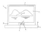
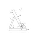
以下、本発明が適用された画像表示装置として、デジタルフォトフレームを例にとり、本発明の実施形態について説明する。まず、図1および図2を参照する。本実施形態のデジタルフォトフレーム1は、略矩形状の表示画面2aを有するディスプレイ2と、撮影部としてのカメラ3を概略備えて構成されている。ディスプレイ2としては、例えば液晶パネルを用いることができる。 Hereinafter, an embodiment of the present invention will be described by taking a digital photo frame as an example of an image display device to which the present invention is applied. First, FIG. 1 and FIG. 2 will be referred to. The
カメラ3は、図示は省略しているが、被写体の像を撮像するCCDなどのイメージセンサおよび被写体の像を該イメージセンサの結像面上に結像させるレンズを備えている。カメラ3は、本実施形態では、ディスプレイ2の正面側であって、表示画面2aの外周に配置されるフレーム(枠部材)の下辺部の略中央部に一体的に固定されており、このデジタルフォトフレーム1に対面するユーザー7の主として手7aを被写体として撮影するものである。カメラ3はその光軸Aの方向(指向方向)が表示画面2a内を通る法線の方向に対して該表示画面2aの前面(正面)側において斜交するように、表示画面2aの外側に配置されている。ここで、カメラ3の光軸Aと表示画面2aの中心(またはその近傍)を通る法線Bとのなす角度をθa、表示画面2aと設置面6aの法線Dとのなす角度をθbとして、θb=0°〜40°の範囲ではθa+θb=70°±10°、θb=40°〜60°の範囲ではθa=30°±10°、θb=60°〜90°の範囲ではθa+θb=90°±10°となるように設定することが好ましい。 Although not shown, the
本実施形態では、カメラ3に隣接して、カメラ3で撮影する際の照明光としての赤外光を発光するLED4が設けられている。LED4は、その光軸の方向(主光線の方向)がカメラ3の光軸Aの方向に略一致するように(すなわち、略平行となるように)フレーム2bに固定されている。但し、後述するように、LED4の光軸の方向は、カメラ3の光軸Aの方向とは異なる方向に設定してもよい。なお、LED4は赤外光を発光するものでなく、可視光を発光するものであってもよい。 In the present embodiment, an
ディスプレイ2の背面側には、ディスプレイ2を設置面(テープル6の上面)6aに設置するためのディスプレイ支持部材としてのスタンド5が回転可能に取り付けられている。スタンド5をディスプレイ2の背面に対して開く方向または閉じる方向に回転させて、所定の角度範囲内の任意の角度に設定することにより、表示画面2aの設置面6aに対する傾き角度を変更することができる。 A
デジタルフォトフレーム1は、フレーム2bの下辺とスタンド5の下端を設置面6a上に当接させて載置することにより、所定の姿勢で設置面6a上に設置される。なお、本実施形態では、カメラ3およびLED4は、フレーム2bに固定されているため、スタンド5の角度を調整して表示画面2aの設置面6aに対する傾き角度を変更した場合には、これに応じてカメラ3の光軸AおよびLED4の光軸Cの設置面6aに対する角度も変更される。なお、表示画面2aの設置面6aに対する傾き角度を変更しても、カメラ3の光軸AおよびLED4の光軸Cの表示画面2aの中心を通る法線Bに対する角度θaは変わらない。 The
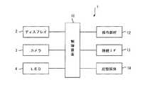
図3に示すように、このデジタルフォトフレーム1は、ディスプレイ2、カメラ3およびLED4を制御する制御装置11を備えており、制御装置11には、操作部材12、接続IF13および記憶媒体14が接続されている。 As shown in FIG. 3, the
制御装置11は、CPU、メモリ、およびその他の周辺回路によって構成され、デジタルフォトフレーム1の全体を制御する。なお、制御装置11を構成するメモリは、例えばSDRAM等の揮発性のメモリである。このメモリは、CPUがプログラム実行時にプログラムを展開するためのワークメモリや、データを一時的に記録するためのバッファメモリを含む。 The control device 11 includes a CPU, a memory, and other peripheral circuits, and controls the entire
制御装置11は、カメラ3が備えるイメージセンサから出力される画像信号に基づいて、画像データを生成する。また、制御装置11はカメラ3による撮影の際に、LED4の点灯もしくは点灯(発光)の強度、または消灯を制御する。 The control device 11 generates image data based on an image signal output from an image sensor included in the
操作部材12は、デジタルフォトフレーム1のユーザー7によって操作される操作ボタン等を含む。接続IF13は、デジタルフォトフレーム1と外部機器とを接続するためのインターフェースである。本実施形態では、デジタルフォトフレーム1は、この接続IF13を介して画像データが記録されている外部機器、例えばデジタルカメラ等と接続される。そして、制御装置11は、接続IF13を介して外部機器から画像データを取り込んで、記憶媒体14に記録する。なお、接続IF13としては、外部機器とデジタルフォトフレーム1とを有線接続するためのUSBインターフェースや、無線接続するための無線LANモジュールなどが用いられる。あるいは、接続IF13の代わりにメモリカードスロットを設け、該メモリカードスロットに画像データが記録されたメモリカードを挿入することにより、画像データを取り込むようにしてもよい。 The
記憶媒体14は、フラッシュメモリ等の不揮発性のメモリであって、制御装置11によって実行されるプログラムや、接続IF13を介して取り込まれた画像データ等が記録される。 The
本実施形態におけるデジタルフォトフレーム1において、制御装置11は、カメラ3によって撮影された画像に基づいてユーザー7の手7aの位置、およびフレーム間での位置の変化を検出し、その検出結果に応じてディスプレイ2上の表示画像2aの再生状態を変更する。再生状態の変更としては、例えば、画像の送り(現在表示中の画像を次に表示予定の画像に変更する)または戻し(現在表示中の画像を直前に表示された画像に変更する)を例示できる。以下、制御装置11による、ユーザー7の手7aの位置、およびフレーム間での位置の変化に応じた画像の再生状態の変更処理について説明する。 In the
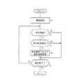
図4は、ユーザー7の手7aの位置、およびフレーム間での位置の変化に応じた画像の再生状態の変更処理の流れを示すフローチャートである。図4に示す処理は、ディスプレイ2への画像の再生表示が開始されると起動するプログラムとして、制御装置11によって実行される。 FIG. 4 is a flowchart showing the flow of processing for changing the reproduction state of an image in accordance with the change in the position of the
ステップS1において、制御装置11は、カメラ3による画像の撮影を開始する。ここでは、カメラ3は、所定のフレームレート(例えば、30fps)で撮影を行うこととし、制御装置11は、カメラ3から該フレームレートに応じた所定の時間間隔で連続して入力された画像データを処理するものとする。また、LED4は点灯させないものとする。但し、制御装置11は、LED4を点灯させて1フレーム分の画像を取り込み、次いでLED4を消灯させて1フレーム分の画像を取り込んで、これらの画像の差分演算を実施して、当該差分に相当する画像(差分画像)に係る画像データを処理するようにしてもよい。このような差分画像を処理することにより、撮影画像内の背景に生じる外乱の影響を軽減することができる。なお、このようにLED4の点灯等を制御して、対象物体の検出精度を高めるための処理(物体検出処理)については、後述する。その後、ステップS2へ進む。 In step S <b> 1, the control device 11 starts capturing an image with the
ステップS2では、制御装置11は、カメラ3から入力される画像データ(差分演算を実施する場合には当該差分画像に係る画像データ)に基づいて、画像内におけるユーザー7の手7aを検出したか否かを判断する。例えば、あらかじめユーザー7の手7aの画像をテンプレート画像として記録しておき、制御装置11は、対象画像とテンプレート画像とをマッチングすることにより、対象画像内にユーザー7の手7aが写っているか否かを判定し、写っていた場合には、その手7aの位置を検出する。ステップS2において、制御装置11は、手7aの位置が検出された場合(Yesの場合)にはステップS3に進み、手7aが検出されなかった場合(Noの場合)にはステップS5に進む。 In step S <b> 2, whether the control device 11 has detected the
ステップS3において、制御装置11は、カメラ3から時系列で入力される画像データ(差分演算を実施する場合には時系列に算出される差部画像に係る画像データ)間での画像内における手7aの位置の変化を監視することにより、ユーザー7の手7aの動きを検出する。ステップS3でユーザー7の手7aの動きを検出しない場合(Noの場合)には、ステップS5へ進む。これに対して、ステップS3でユーザー7の手7aの動きを検出した場合(Yesの場合)には、ステップS4へ進む。 In step S <b> 3, the control device 11 performs the operation in the image between the image data input in time series from the camera 3 (image data related to the difference image calculated in time series when the difference calculation is performed). The movement of the
ステップS4において、制御装置11は、手7aの動きに応じて再生画像を変更する。すなわち、制御装置11は、手7aが右から左に移動したことが検出された場合には、ユーザー7により画像送りが指示されたと判断し、ディスプレイ2上に現在表示中の画像を左方向に移動して画面左辺から画面外に排出するように表示させるとともに、次に表示予定の画像を画面右辺から画面内に導入するように表示させて、当該次に表示予定の画像をディスプレイ2上に表示させる。 In step S4, the control device 11 changes the reproduced image according to the movement of the
これと逆に、制御装置11は、手7aが左から右に移動したことが検出された場合には、ユーザー7により画像戻しが指示されたと判断し、ディスプレイ2上に現在表示中の画像を右方向に移動して画面右辺から画面外に排出するように表示させるとともに、直前に表示した画像を画面左辺から画面内に導入するように表示させて、当該直前に表示させた画像をディスプレイ2上に表示させる。 On the contrary, when it is detected that the
なお、ここでは、ユーザー7の手7aの左右の動きに応じて、画像送りまたは戻しを行うようにしたが、他の動きを検出して、他の処理を行うようにしてもよい。例えば、ユーザー7の手7aの位置に対応して画面内に所定形状のカーソルを表示し、手7aの動きに応じて該カーソルを画面内で移動させて、画面内に表示させた指示入力用のアイコンなどを選択させるようにしてもよい。また、例えば、手7aの上下の動きを検出して、画像の表示倍率を変更するようにしてもよい。 Here, the image is forwarded or returned in accordance with the left / right movement of the
その後、ステップS5において、制御装置11は、ユーザー7によって、画像の再生を終了するように指示されたか否かを判断する。ステップS5で終了が指示されていない場合(Noの場合)にはステップS2に戻り、終了が指示された場合(Yesの場合)にはこの処理を終了する。 Thereafter, in step S5, the control device 11 determines whether or not the user 7 has instructed to end the reproduction of the image. If termination is not instructed in step S5 (in the case of No), the process returns to step S2, and if termination is instructed (in the case of Yes), this process is terminated.
以上説明した本実施形態によれば、カメラ3の光軸Aの方向が表示画面2a内を通る法線(本実施形態では一例として表示画面2a内の中心を通る法線B)の方向に対して該表示画面2aの前面側において例えば30°程度で斜交するように、表示画面2aの外側に配置されている。これにより、ユーザー7のモーション操作を行う手7aの検出範囲を装置近辺に限定することができる。すなわち、カメラ3の視野内には、ユーザー7のモーション操作を行う手7aまたはその近傍は入るが、ユーザー7の後方の背景は入らないようにできるため、例えばユーザー7の後方を他人が横切った場合でも、撮影範囲に入らず、当該他人の一部を検出してしまうことによる誤検出を防止することができる。 According to the present embodiment described above, the direction of the optical axis A of the
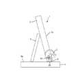
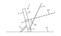
次に、上述したデジタルフォトフレーム1の第1変形例について、図5および図6を参照して説明する。図1〜図3と実質的に同一の構成部分については同一の符号を付し、その説明は省略する。すなわち、上述した実施形態では、カメラ3はディスプレイ2のフレーム2bの下辺部の略中央部に固定されているものとして説明した。したがって、スタンド5の角度を変更して表示画面2aの傾きを変更した場合には、これに伴いカメラ3の指向方向も変更されることになる。 Next, a first modification of the
これに対し、この第1変形例では、ディスプレイ支持部材としてのスタンド5の角度を変更して表示画面2aの傾きを変更した場合であっても、カメラ3の指向方向は変更されないような構成としている。すなわち、カメラ3はカメラ支持部材8に固定されており、カメラ支持部材8はフレーム2bの下辺近傍に該下辺に略平行な方向に設定された回転軸8aを介して回転自在に支持されている。また、カメラ支持部材8は、このデジタルフォトフレーム1を持ち上げた状態で、重力の作用によりカメラ3を略一定方向を指向させるようなある程度の偏荷重を有しており、その下面は平坦に形成された当接面8bとなっている。このデジタルフォトフレーム1を設置面6a上に設置すると、カメラ支持部材8の当接面8bが設置面6aに当接して、カメラ支持部材8の回転が制限され、カメラ3が一定方向を指向するようになっている。これにより、例えば、図5の状態から図6の状態となるように、ディスプレイ2の傾きを変更しても、カメラ3の指向方向(光軸Aの方向)は変更されず、一定方向を指向することになる。 On the other hand, in the first modified example, the orientation of the
なお、LED4をカメラ支持部材8に固定して、ディスプレイ2の傾きを変更した場合にも、LED4の指向方向(光軸の方向)がカメラ3の指向方向(光軸Aの方向)と同様に一定方向を指向するようにしてもよい。 Even when the
次に、上述したデジタルフォトフレーム1の第2変形例について、図7および図8を参照して説明する。図1〜図3と実質的に同一の構成部分については同一の符号を付し、その説明は省略する。すなわち、この第2変形例も、上述した第1変形例と同様に、表示画面2aの傾きを変更した場合であっても、カメラ3の指向方向は変更されないような構成としている。すなわち、この第2変形例では、スタンド5の代わりに、ディスプレイ支持部材としての台座9を設け、この台座9にディスプレイ2と回転軸9aを介して回転可能に軸支している。ディスプレイ2の回転は台座9に対する支持部において自己の姿勢を保持し得る程度の抵抗を受けており、ユーザー7が手で押圧することにより姿勢変更できるが、押圧しない状態ではその姿勢を保つようになっている。カメラ3は、台座9に所定方向を指向して固定されている。これにより、例えば、図7の状態から図8の状態となるように、ディスプレイ2の傾きを変更しても、カメラ3の指向方向(光軸Aの方向)は変更されず、一定方向を指向することになる。 Next, a second modification of the
なお、LED4を台座9に所定方向を指向させて固定して、ディスプレイ2の傾きを変更した場合にも、LED4の指向方向(光軸Cの方向)がカメラ3の指向方向(光軸Aの方向)と同様に一定方向を指向するようにしてもよい。 Even when the
次に、本発明の他の実施形態として、LED4の配置について、詳述する。例えば、図9に示すように、LED4は、ディスプレイ2の正面側であって、表示画面2aの外周に配置されるフレーム(枠部材)の下辺部の略中央部に一体的に固定するとともに、その光軸Cの方向(指向方向)が表示画面2a内を通る法線Bの方向に対して該表示画面2aの前面(正面)側において斜交するように、表示画面2aの外側に配置するようにできる。 Next, as another embodiment of the present invention, the arrangement of the
LED4の光軸Cの表示画面2aの中心(またはその近傍)を通る法線Bに対する角度θ2は、例えば、θ2=40°±20°の範囲内となるように設定されている。この角度θ2は、ディスプレイ2の表示画面2aのサイズに応じて適宜に設定され、角度θ2は、θ2=40°±10°程度がより好ましく、θ2=40°程度が最も好ましい。 The angle θ2 of the optical axis C of the
このように、LED4をその光軸Cの方向が表示画面2a内を通る法線Bに対して斜交するように配置することにより、検出の対象物体としてのユーザー7のモーション操作を行う手7aはLED4からの照明光により照明されるが、該手7a以外のユーザーの身体や後方の背景は照明されず、撮影画像内では、対象物体としての手7aが明るく、その余の部分は暗くなるため、適宜なしきい値を設定することによって、当該手7aの検出精度を向上させることができる。 In this way, by arranging the
なお、図9では、カメラ3は、表示画面2aの外周に配置されるフレームの上辺の略中央部に固定しているが、図10に示すように、該フレームの側辺(左辺または右辺)の略中央部に固定してもよい。また、図示は省略するが、図9において、カメラ3とLED4の位置を逆に、すなわち、カメラ3の位置にLED4を、LED4の位置にカメラ3を配置するようにしてもよい。なお、これらの場合におけるカメラ3の光軸Aの方向は、表示画面2a内を通る法線Bに対して実質的に平行であっても、上述したように斜交していても何れでもよい。 In FIG. 9, the
カメラ3の光軸Aの方向とLED4の光軸Cの方向との両者を、表示画面2a内を通る法線Bに対して斜交させる場合には、例えば、図11に示すように、カメラ3およびLED4を表示画面2aの外周を構成するフレームの下辺の略中央部に互いに隣接させて配置し、カメラ3の光軸Aの表示画面2a内を通る法線Bに対する角度θaとLED4の光軸Cの該法線Bに対する角度θ2を実質的に等しく設定してもよい。こうすることにより、カメラ3の光軸Aを該法線Bに対して斜交させることによる検出精度の向上の効果と、LED4の光軸Cを該法線Bに対して斜交させることによる検出精度の向上の効果とを相乗的に実現することが可能である。 When the direction of the optical axis A of the
なお、図12に示したようにカメラ3およびLED4を配置して、カメラ3の光軸Aの表示画面2a内を通る法線Bに対する角度θaとLED4の光軸Cの該法線Bに対する角度θ2を実質的に等しく設定しても同様に効果的である。 As shown in FIG. 12, the
また、カメラ3の光軸Aの方向とLED4の光軸Cの方向との両者を、表示画面2a内を通る法線Bに対して斜交させる場合において、カメラ3の光軸Aの表示画面2a内を通る法線Bに対する角度θaとLED4の光軸Cの該法線Bに対する角度θ2を互いに異なる角度に設定する場合(例えば、図9に示すような場合)には、θa<θ2となるように設定することが好ましく、この場合の相対的な角度差(θ2−θa)は10°程度に設定することができる。この場合において、カメラ3とLED4とを一体的に構成してユニット化し、相対的な角度差(θ2−θa)は固定として、当該ユニットをフレームに対して回転可能に軸支して、その傾きを調整できるようにするとよい。カメラ3単体またはLED4単体をフレームに対してそれぞれ回転可能に軸支して、それぞれの傾きを調整できるようにしてもよい。 Further, when both the direction of the optical axis A of the
カメラ3、LED4、またはこれらを一体化したユニットの傾きの調整は、手動で行い得るようにしてもよいし、モータ駆動等により行うようにしてもよい。モータ駆動等により行う場合には、ディスプレイ2に加速度センサを設けて、表示画面2aの設置面に対する角度を検出し得るようにして、検出した角度に応じて、カメラ3、LED4、またはカメラ3及びLED4を一体化したユニットの傾きを自動的に調整できるようにしてもよい。また、スタンド5の開閉角度または開閉位置を検出して、設置面が机か壁か等を判断し、その状況に応じて、カメラ3、LED4、またはカメラ3及びLED4を一体化したユニットの傾きを自動的に調整できるようにしてもよい。さらに、気圧センサ等を設けて、ディスプレイ2の高さ位置を検出し、検出された高さ位置に応じて、カメラ3、LED4、またはカメラ3及びLED4を一体化したユニットの傾きを自動的に調整できるようにしてもよい。上述した各検出結果を組み合わせた検出結果に応じて、カメラ3、LED4、またはカメラ3及びLED4を一体化したユニットの傾きを自動的に調整できるようにしてもよい。 Adjustment of the tilt of the
次に、本実施形態の画像表示装置において、検出の対象物体としてのユーザーの手7aを検出するための第1の物体検出処理(物体検出装置)について、図13および図14を参照して説明する。 Next, in the image display apparatus of the present embodiment, a first object detection process (object detection apparatus) for detecting the user's
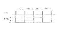
図13において、上段「vsync」はカメラ3を構成する撮像素子(イメージセンサ)の画像取込のタイミング(左からnフレーム、n+1フレーム、n+2フレーム、n+3フレーム:nは1,2,3,…)であり、下段「赤外光」はLED4の照明光(ここでは赤外光とする)の光強度変化のタイミングを示している。 In FIG. 13, the upper stage “vsync” indicates image capture timing of the image sensor (image sensor) constituting the camera 3 (n frames from the left, n + 1 frames, n + 2 frames, n + 3 frames: n is 1, 2, 3,... The lower “infrared light” indicates the timing of the change in the light intensity of the illumination light of the LED 4 (here, infrared light).
制御装置11は、カメラ3の撮像素子のフレームレートに同期して、LED4に第1光強度で発光するよう電圧を印加する強発光モードと、該第1光強度よりも小さく且つ光強度零よりも大きい第2光強度で発光するよう電圧を印加する弱発光モードとを選択的に順次に(交互に)切換制御する。ここで、光強度零とは、電圧を印加しない状態、すなわち消灯した状態を示し、したがって、ここでの弱発光モードは消灯した状態を含まない。なお、簡単のため、本実施形態では、第1光強度を100%として、第2光強度は半分の50%の光強度であるものとする。すなわち、nフレーム目の画像が取得される際には、LED4が強発光モードで発光され、n+1フレーム目の画像が取得される際には、LED4は弱発光モードで発光され、順次、強発光モード及び弱発光モードが繰り返される。 The control device 11 synchronizes with the frame rate of the image sensor of the
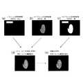
図14(a)〜図14(d)は、第1の物体検出処理を説明するための図である。図14(a)はLED4が強発光モード(第1光強度)で発光された際に取得されたnフレーム目の画像を、図14(b)はLED4が弱発光モード(第2光強度)で発光された際に取得されたn+1フレーム目の画像を模式的に示している。 FIG. 14A to FIG. 14D are diagrams for explaining the first object detection process. FIG. 14A shows an n-th frame image obtained when the
なお、図14(a)において、左上部の横長長方形で示すのは、点滅照明(蛍光灯や粗悪なLED電球等)が点灯した際の光が外乱として写り込んでいることを示しており、図14(b)では当該点滅光源が消灯しているため、そのような外乱が写り込んでいないことを示している。画像の中央部に略手の形状で示すのは、検出対象物体としてのユーザーの手7aに係る画像であり、図14(a)ではLED4が強発光モードで発光されているため白色(100%の光強度)で写り込んでおり、図14(b)ではLED4が弱発光モードで発光されているため灰色(50%の光強度)で写り込んでいる状態が示されている。 In addition, in FIG. 14A, the horizontal rectangle at the upper left indicates that the light when the flashing illumination (fluorescent lamp, bad LED bulb, etc.) is turned on is reflected as a disturbance, FIG. 14B shows that such a disturbance is not reflected because the flashing light source is turned off. A substantially hand shape shown in the center of the image is an image relating to the user's
まず、図14(a)のnフレーム目取得画像と、図14(b)のn+1フレーム目取得画像との差分{(n+1)−(n)}の画像を求める。この差分の画像は、両画像の対応する画素の輝度値の差をとった画像である。この差分の画像が図14(c)に示されている。この段階では、差分をとっただけなので、外乱(横長長方形)が残っており、このままでは、検出対象としての手7aに係る画像の十分な検出精度を得ることはできない。 First, an image of a difference {(n + 1) − (n)} between the nth frame acquired image in FIG. 14A and the n + 1th frame acquired image in FIG. 14B is obtained. This difference image is an image obtained by taking a difference in luminance value between corresponding pixels of both images. An image of this difference is shown in FIG. At this stage, since only the difference is taken, disturbance (horizontal rectangle) remains, and with this state, sufficient detection accuracy of the image related to the
そこで、この第1の物体検出処理では、照明光の光強度を変化させることにより、外乱に係る部分を、検出対象としての手7aに係る画像と区別して、外乱のみを排除するようにしている。すなわち、図14(d)に示すように、nフレーム目では強発光モードに係る第1光強度(100%)で発光させているのに対して、n+1フレーム目では弱発光モードに係る第2光強度(50%)で発光させているので、検出対象としての手7aに係る画像の明るさ(輝度)は、略{(第2光強度)−(第1光強度)}、すなわち、50%−100%=−50%程度となる。したがって、−50%近傍の輝度をもつ画素に係る画像は検出対象としての手7aに係る画像であると判断でき、これに対して、外乱がnフレーム目では例えば90%であるならば、n+1フレーム目では0%であるから、第2光強度と第1光強度との差分は0%−90%=−90%となり、検出対象としての手7aに係る画像と、外乱に係る画像とを区別することができる。 Therefore, in the first object detection process, by changing the light intensity of the illumination light, the part related to the disturbance is distinguished from the image related to the
したがって、画像抽出のしきい値として、例えば、−50±10%を設定して、この範囲以外の輝度をもつ画素に係る画像は外乱として消去することにより、図14(d)に示すように、手7aに係る画像部分のみを抽出した画像を得ることができる。したがって、検出対象としての手7aに係る画像の検出精度を向上させることができる。 Therefore, for example, by setting -50 ± 10% as a threshold value for image extraction, and deleting an image related to a pixel having a luminance outside this range as a disturbance, as shown in FIG. An image obtained by extracting only the image portion related to the
次に、本実施形態の画像表示装置において、検出の対象物体としてのユーザーの手7aを検出するための第2の物体検出処理(物体検出装置)について、図15および図16を参照して説明する。 Next, in the image display device of the present embodiment, a second object detection process (object detection device) for detecting the user's
図15において、上段「vsync」はカメラ3を構成する撮像素子(イメージセンサ)の画像取込のタイミング(左からnフレーム、n+1フレーム、n+2フレーム、n+3フレーム:nは1,2,3,…)であり、下段「赤外光」はLED4の照明光(ここでは赤外光とする)の強度変化のタイミングを示している。 In FIG. 15, the upper “vsync” indicates image capture timing of the image sensor (image sensor) constituting the camera 3 (n frames from the left, n + 1 frames, n + 2 frames, n + 3 frames: n is 1, 2, 3,... The lower “infrared light” indicates the intensity change timing of the illumination light of the LED 4 (in this case, infrared light).
制御装置11は、カメラ3の撮像素子のフレームレートに同期して、LED4に第1光強度で発光するよう電圧を印加する強発光モードと、該第1光強度よりも小さく且つ光強度零よりも大きい第2光強度で発光するよう電圧を印加する弱発光モードと、光強度零とする(すなわち電圧を印加しなで消灯させる)消灯モードとを選択的に順次に切換制御する。ここでは、消灯モード、弱発光モード、強発光モードの順に繰り返し発光させるものとする。なお、簡単のため、ここでは、第1光強度(強)を100%として、第2光強度(弱)は半分の50%の光強度であるものとし、消灯は光強度零である。すなわち、nフレーム目の画像が取得される際には、LED4が消灯され、n+1フレーム目の画像が取得される際には、LED4は弱発光モードで発光され、n+2フレーム目の画像が取得される際には、LED4は強発光モードで発光され、順次、消灯モード、弱発光モード、強発光モードが繰り返される。 The control device 11 synchronizes with the frame rate of the image sensor of the
図16(a)〜図16(d)は、この第2物体検出処理を説明するための図である。図16(a)はLED4が消灯された際に取得されたnフレーム目の画像を示しており、図16(b)はLED4が弱発光モード(第2光強度)で発光された際に取得されたn+1フレーム目の画像を示しており、図16(c)がLED4が強発光モードで発光された際に取得されたn+2フレーム目の画像を示している。 FIG. 16A to FIG. 16D are diagrams for explaining the second object detection process. FIG. 16A shows an image of the nth frame acquired when the
なお、図16(a)および図16(c)において、左上部に横長長方形で示すのは、点滅照明(蛍光灯や粗悪なLED電球等)が点灯した際の光が外乱として写り込んでいることを示しており、図16(b)では当該点滅照明が消灯しているため、そのような外乱が写り込んでいないことを示している。画像の中央部に略手の形状で示すのは、検出対象物体としてのユーザーの手7aに係る画像であり、図16(a)ではLED4が消灯されているため殆ど移っておらず、図16(b)ではLED4が弱発光モードで発光されているため灰色(50%の光強度)で写り込んでおり、図16(c)ではLED4が強発光モードで発光されているため白色(50%の光強度)で写り込んでいる状態が示されている。 In FIGS. 16 (a) and 16 (c), a horizontally long rectangle is shown at the upper left, and the light when flashing illumination (fluorescent lamp, bad LED bulb, etc.) is turned on is reflected as disturbance. In FIG. 16B, the blinking illumination is turned off, and it is shown that such a disturbance is not reflected. A substantially hand shape shown in the center of the image is an image relating to the user's
nフレーム〜n+2フレームに着目すると、LED4によって照明された検出対象としての手7aに係る部分(画素)は、LED4の発光強度の変化に応じて段階的に変化する(ここでは、明るくなる)。したがって、図16(a)のnフレーム目取得画像、図16(b)のn+1フレーム目取得画像、および図16(c)のn+2フレーム目取得画像の3つのフレームに係る画像を比較して、(n<n+1<n+2)と変化する画素値だけを抽出することで、外乱を排除することができる。 Focusing on n frames to n + 2 frames, the portion (pixel) related to the
上述した第2の物体検出処理においては、LED4を強発光モード、弱発光モード、および消灯モードの3つのモードで発光(または消灯)させるようにしたが、強発光モードと弱発光モードの間の光強度で発光するモード、および/または弱発光モードと消灯モードの間の光強度で発光するモードを設定するなどして、4フレーム以上に係る画像を用いるようにしてもよい。また、消灯モードを省略して、弱発光モードに係る第2光強度よりも小さい第3光強度で発光するモードを設定してもよい。 In the second object detection process described above, the
ここで、図17および図18に示すように、LED4による発光(光強度変化)の順番を上記とは逆にしてもよい。すなわち、強発光モード、弱発光モード、消灯モードの順に繰り返し発光させるようにしてもよい。この場合の処理は、図15および図16に示したものと同様であるのでその説明は省略する。なお、この場合には、図18(a)のnフレーム目取得画像、図18(b)のn+1フレーム目取得画像、および図18(c)のn+2フレーム目取得画像の3つのフレームに係る画像を比較して、(n>n+1>n+2)と変化する画素値だけを抽出することで、外乱を排除することができる。 Here, as shown in FIGS. 17 and 18, the order of light emission (light intensity change) by the
次に、本実施形態の画像表示装置において、検出の対象物体としてのユーザーの手7aを検出するための第3の物体検出処理(物体検出装置)について、図19および図20を参照して説明する。 Next, in the image display device of this embodiment, a third object detection process (object detection device) for detecting the user's
図19において、上段「vsync」はカメラ3を構成する撮像素子(イメージセンサ)の画像取込のタイミング(左からnフレーム、n+1フレーム、n+2フレーム、n+3フレーム:nは1,2,3,…)であり、下段「赤外光」はLED4の照明光(ここでは赤外光とする)の光強度変化のタイミングを示している。 In FIG. 19, the upper “vsync” indicates image capture timing of the image sensor (image sensor) constituting the camera 3 (n frames from the left, n + 1 frames, n + 2 frames, n + 3 frames: n is 1, 2, 3,... The lower “infrared light” indicates the timing of the change in the light intensity of the illumination light of the LED 4 (here, infrared light).
制御装置11は、カメラ3の撮像素子のフレームレートに同期して、LED4に第1光強度で発光するよう電圧を印加する強発光モードと、該第1光強度よりも小さく且つ光強度零よりも大きい第2光強度で発光するよう電圧を印加する弱発光モードと、光強度零とする(すなわち電圧を印加しなで消灯させる)消灯モードとを選択的に順次に切換制御する。ここでは、消灯モード、弱発光モード、強発光モードの順に繰り返し発光させるものとする。なお、簡単のため、本実施形態では、第1光強度を100%として、第2光強度は半分の50%の光強度であるものとし、消灯は光強度零である。すなわち、nフレーム目の画像が取得される際には、LED4が消灯され、n+1フレーム目の画像が取得される際には、LED4は弱発光モードで発光され、n+2フレーム目の画像が取得される際には、LED4は強発光モードで発光され、順次、消灯モード、弱発光モード、強発光モードが繰り返される。 The control device 11 synchronizes with the frame rate of the image sensor of the
図20(a)〜図20(d)は、この第3の物体検出処理を説明するための図である。図20(a)はLED4が消灯された際に取得されたnフレーム目の画像を示しており、図20(b)はLED4が弱発光モード(第2光強度)で発光された際に取得されたn+1フレーム目の画像を示しており、図20(c)はLED4が強発光モードで発光された際に取得されたn+2フレーム目の画像を示している。 FIG. 20A to FIG. 20D are diagrams for explaining the third object detection process. FIG. 20A shows an image of the nth frame acquired when the
なお、図20(a)および図20(c)において、左上部に横長長方形で示すのは、点滅照明(蛍光灯や粗悪なLED電球等)が点灯した際の光が外乱として写り込んでいることを示しており、図20(b)では当該点滅照明が消灯しているため、そのような外乱が写り込んでいないことを示している。画像中央部に略手の形状で示すのは、検出対象物体としてのユーザーの手7aに係る画像であり、図20(a)ではLED4が消灯されているため殆ど移っておらず、図20(b)ではLED4が弱発光モードで発光されているため灰色(50%の光強度)で写り込んでおり、図20(c)ではLED4が強発光モードで発光されているため白色(50%の光強度)で写り込んでいる状態が示されている。 In FIGS. 20 (a) and 20 (c), a horizontally long rectangle is shown in the upper left corner, and the light when the flashing illumination (fluorescent lamp, bad LED bulb, etc.) is turned on is reflected as a disturbance. In FIG. 20B, since the blinking illumination is turned off, it is shown that such a disturbance is not reflected. A substantially hand shape shown in the center of the image is an image related to the user's
上述した第2の物体検出処理では、3つのフレームに係る画像間で輝度変化の大小関係で画素を抽出し、対象物体の検出を行うようにしたが、この第3の物体検出処理では、LED4の発光強度の変化率(例えば、ここでは増加量に対する比率)で抽出する画素を選択するようにしている。 In the second object detection process described above, pixels are extracted based on the magnitude change in luminance between the images related to the three frames and the target object is detected. In this third object detection process, the
まず、図20(a)のnフレーム目取得画像と、図20(b)のn+1フレーム目取得画像とで差分を取って、発光強度の増加量にあった比率で画像の輝度が上がった箇所だけを取得する。この中にも含まれるノイズ(例えば、点滅した照明光)を消すために、さらにn+2フレーム目取得画像で差分を取る。このときも同様に発光強度の増加量にあった比率で明るくなった画素を抽出することで、対象物体だけを抽出することができる。このような処理とすることにより、物体の検出精度をさらに高めることができる。 First, a difference between the nth frame acquired image in FIG. 20A and the n + 1th frame acquired image in FIG. 20B is obtained, and the brightness of the image is increased at a ratio corresponding to the increase in emission intensity. Just get. In order to eliminate noise (for example, blinking illumination light) included in this, a difference is further obtained from the acquired image of the (n + 2) th frame. At this time as well, only the target object can be extracted by extracting pixels that become bright at a ratio corresponding to the amount of increase in emission intensity. By setting it as such a process, the detection accuracy of an object can further be improved.
なお、上述した第1〜第3の物体検出処理を、点滅光源等による外乱の性質に応じて、選択的に実施できるようにするとよい。例えば、カメラ3の視野内に存在する照明(点滅光源等)の特性を検出する照明特性検出部として、輝度センサを設けて、点滅光源の点滅の周波数を検出し、検出した周波数に基づいて、第1〜第3の物体検出処理のうち最適なものを自動的に選択して、実行するようにしてもよい。このような輝度センサに代えて、カメラ3で撮像した画像から視野内に存在する照明(点滅光源等)の特性を検出するようにしてもよい。 The first to third object detection processes described above may be selectively performed according to the nature of the disturbance caused by the blinking light source or the like. For example, as an illumination characteristic detection unit that detects the characteristics of illumination (flashing light source or the like) existing in the field of view of the
上述した実施形態では、画像表示装置としてデジタルフォトフレームを用いる場合について説明した。しかしながら、モーション検出用のカメラとディスプレイとを備え、画像再生機能を有する他の機器、例えば、パーソナルコンピュータ、タブレット型コンピュータ、デジタルカメラ、携帯電話、PDA、デジタルテレビジョン受像機などにも本発明を適用することができる。 In the above-described embodiment, the case where a digital photo frame is used as the image display device has been described. However, the present invention is also applied to other devices having a motion detection camera and a display and having an image reproduction function, such as a personal computer, a tablet computer, a digital camera, a mobile phone, a PDA, and a digital television receiver. Can be applied.
なお、以上説明した実施形態は、本発明の理解を容易にするために記載されたものであって、本発明を限定するために記載されたものではない。したがって、上記の実施形態に開示された各要素は、本発明の技術的範囲に属する全ての設計変更や均等物をも含む趣旨である。 The embodiment described above is described for facilitating the understanding of the present invention, and is not described for limiting the present invention. Therefore, each element disclosed in the above embodiment is intended to include all design changes and equivalents belonging to the technical scope of the present invention.
1…デジタルフォトフレーム、2…ディスプレイ、2a…表示画面、3…カメラ、4…LED、5…スタンド、6…テーブル、6a…設置面、7…ユーザー、7a…手、8…カメラ支持部材、8a…回転軸、8b…当接面、9…台座、9a…回転軸、11…制御装置、A…カメラの光軸、B…表示画面の中心を通る法線、C…LEDの光軸、D…設置面の法線。 DESCRIPTION OF
Claims (7)
Translated fromJapanese光軸と前記表示画面の法線とが前記表示画面の前面側において斜交するように前記表示画面の外側に配置され、前記光軸の方向を逐次撮影して撮影画像を取得する撮影部と、
前記撮影部で撮影された撮影画像の変化を検出する検出部と、
を備えることを特徴とする画像表示装置。A display having a display screen;
An imaging unit that is arranged outside the display screen so that an optical axis and a normal line of the display screen intersect obliquely on the front side of the display screen, and sequentially captures the direction of the optical axis to acquire a captured image; ,
A detection unit for detecting a change in a photographed image photographed by the photographing unit;
An image display device comprising:
前記撮影部は、前記ディスプレイに回転自在に軸支された支持部材に固定されており、
前記支持部材は、前記ディスプレイを前記設置面上に設置した際に前記設置面に当接して、前記ディスプレイの前記設置面に対する傾きにかかわらず、前記撮影部が一定方向を指向するようにその回転位置を規制する当接面を有することを特徴とする請求項1〜3の何れか一項に記載の画像表示装置。A display support member that supports the display so that the inclination of the display screen relative to the installation surface can be changed
The photographing unit is fixed to a support member that is rotatably supported by the display,
The support member abuts on the installation surface when the display is installed on the installation surface, and rotates so that the photographing unit is oriented in a certain direction regardless of the inclination of the display with respect to the installation surface. The image display device according to claim 1, further comprising a contact surface for regulating a position.
前記撮影部は、前記ディスプレイの前記設置面に対する傾きにかかわらず、一定方向を指向するように前記ディスプレイ支持部材に固定されることを特徴とする請求項1〜3の何れか一項に記載の画像表示装置。A display support member that supports the display so that the inclination of the display screen relative to the installation surface can be changed
The said imaging | photography part is fixed to the said display support member so that it may face a fixed direction irrespective of the inclination with respect to the said installation surface of the said display, The Claim 1 characterized by the above-mentioned. Image display device.
前記撮影部は前記表示画面の下辺近傍の略中央部分に配置されることを特徴とする請求項1〜5の何れか一項に記載の画像表示装置。The display screen is substantially rectangular,
The image display device according to claim 1, wherein the photographing unit is disposed in a substantially central portion near a lower side of the display screen.
Priority Applications (4)
| Application Number | Priority Date | Filing Date | Title |
|---|---|---|---|
| JP2011080355AJP5862034B2 (en) | 2011-03-31 | 2011-03-31 | Image display device |
| CN2012800053826ACN103329519A (en) | 2011-03-31 | 2012-03-16 | Image display device and object detection device |
| US13/985,222US20130321643A1 (en) | 2011-03-31 | 2012-03-16 | Image display device and object detection device |
| PCT/JP2012/056838WO2012132955A1 (en) | 2011-03-31 | 2012-03-16 | Image display device and object detection device |
Applications Claiming Priority (1)
| Application Number | Priority Date | Filing Date | Title |
|---|---|---|---|
| JP2011080355AJP5862034B2 (en) | 2011-03-31 | 2011-03-31 | Image display device |
Related Child Applications (1)
| Application Number | Title | Priority Date | Filing Date |
|---|---|---|---|
| JP2015249256ADivisionJP2016106289A (en) | 2015-12-22 | 2015-12-22 | Imaging apparatus |
Publications (3)
| Publication Number | Publication Date |
|---|---|
| JP2012216030Atrue JP2012216030A (en) | 2012-11-08 |
| JP2012216030A5 JP2012216030A5 (en) | 2014-10-09 |
| JP5862034B2 JP5862034B2 (en) | 2016-02-16 |
Family
ID=47268746
Family Applications (1)
| Application Number | Title | Priority Date | Filing Date |
|---|---|---|---|
| JP2011080355AExpired - Fee RelatedJP5862034B2 (en) | 2011-03-31 | 2011-03-31 | Image display device |
Country Status (1)
| Country | Link |
|---|---|
| JP (1) | JP5862034B2 (en) |
Cited By (2)
| Publication number | Priority date | Publication date | Assignee | Title |
|---|---|---|---|---|
| JP2014178507A (en)* | 2013-03-15 | 2014-09-25 | Casio Comput Co Ltd | Display device and program |
| JP2018536183A (en)* | 2015-09-28 | 2018-12-06 | アップル インコーポレイテッドApple Inc. | Electronic device display with extended active area |
Citations (6)
| Publication number | Priority date | Publication date | Assignee | Title |
|---|---|---|---|---|
| JPH08211979A (en)* | 1995-02-02 | 1996-08-20 | Canon Inc | Hand gesture input device and method |
| JPH10177449A (en)* | 1996-10-18 | 1998-06-30 | Toshiba Corp | Information input device, information input method, correction data generation device, and solid-state imaging device |
| JP2001142564A (en)* | 1999-11-11 | 2001-05-25 | Sharp Corp | Information equipment |
| JP2007272596A (en)* | 2006-03-31 | 2007-10-18 | Denso Corp | Operation object extracting device for mobile body |
| US20090189858A1 (en)* | 2008-01-30 | 2009-07-30 | Jeff Lev | Gesture Identification Using A Structured Light Pattern |
| JP2011060337A (en)* | 2004-08-31 | 2011-03-24 | Panasonic Electric Works Co Ltd | Gesture switch |
- 2011
- 2011-03-31JPJP2011080355Apatent/JP5862034B2/ennot_activeExpired - Fee Related
Patent Citations (6)
| Publication number | Priority date | Publication date | Assignee | Title |
|---|---|---|---|---|
| JPH08211979A (en)* | 1995-02-02 | 1996-08-20 | Canon Inc | Hand gesture input device and method |
| JPH10177449A (en)* | 1996-10-18 | 1998-06-30 | Toshiba Corp | Information input device, information input method, correction data generation device, and solid-state imaging device |
| JP2001142564A (en)* | 1999-11-11 | 2001-05-25 | Sharp Corp | Information equipment |
| JP2011060337A (en)* | 2004-08-31 | 2011-03-24 | Panasonic Electric Works Co Ltd | Gesture switch |
| JP2007272596A (en)* | 2006-03-31 | 2007-10-18 | Denso Corp | Operation object extracting device for mobile body |
| US20090189858A1 (en)* | 2008-01-30 | 2009-07-30 | Jeff Lev | Gesture Identification Using A Structured Light Pattern |
Cited By (7)
| Publication number | Priority date | Publication date | Assignee | Title |
|---|---|---|---|---|
| JP2014178507A (en)* | 2013-03-15 | 2014-09-25 | Casio Comput Co Ltd | Display device and program |
| JP2018536183A (en)* | 2015-09-28 | 2018-12-06 | アップル インコーポレイテッドApple Inc. | Electronic device display with extended active area |
| US10607573B2 (en) | 2015-09-28 | 2020-03-31 | Apple Inc. | Electronic device display with extended active area |
| US11521577B2 (en) | 2015-09-28 | 2022-12-06 | Apple Inc. | Electronic device display with extended active area |
| US11521579B2 (en) | 2015-09-28 | 2022-12-06 | Apple Inc. | Electronic device display with extended active area |
| US11823645B2 (en) | 2015-09-28 | 2023-11-21 | Apple Inc. | Electronic device display with extended active area |
| US12183307B2 (en) | 2015-09-28 | 2024-12-31 | Apple Inc. | Electronic device display with extended active area |
Also Published As
| Publication number | Publication date |
|---|---|
| JP5862034B2 (en) | 2016-02-16 |
Similar Documents
| Publication | Publication Date | Title |
|---|---|---|
| US9307143B2 (en) | Multimodal camera and a method for selecting an operation mode of a camera | |
| WO2012132955A1 (en) | Image display device and object detection device | |
| US20180227573A1 (en) | Electronic device having dynamically controlled flashlight for image capturing and related control method | |
| JP4707034B2 (en) | Image processing method and input interface device | |
| CN107426470A (en) | Camera module and electronic installation | |
| KR102508108B1 (en) | Image acquisition module, electronic equipment, image acquisition method and storage medium | |
| CN107426471B (en) | Camera module and electronic device | |
| US10382734B2 (en) | Electronic device and color temperature adjusting method | |
| US20250159099A1 (en) | Video creation method | |
| JP5862034B2 (en) | Image display device | |
| US20060125926A1 (en) | Image-taking apparatus | |
| JP2016106289A (en) | Imaging apparatus | |
| JP5862035B2 (en) | Object detection device | |
| JP2012216032A (en) | Image display device | |
| JPWO2018150961A1 (en) | Imaging apparatus, control method thereof, and operation program | |
| US9699385B2 (en) | Imaging apparatus and storage medium, and exposure amount control method | |
| JP2016119098A (en) | Control device | |
| US20220279106A1 (en) | Video creation method | |
| CN117425002A (en) | Method and device for detecting infrared light-emitting equipment and detection equipment | |
| CN113596333A (en) | Desk lamp and control method, device, equipment and storage medium thereof | |
| JP2019057902A (en) | Imaging apparatus, imaging method, and program | |
| JP2016187180A (en) | Control device and program | |
| JP2012141475A (en) | Image pickup apparatus and imaging method | |
| CN106200934A (en) | Control method, control device and electronic installation | |
| KR20170123742A (en) | Apparatus for controlling brighting of prpjector |
Legal Events
| Date | Code | Title | Description |
|---|---|---|---|
| A621 | Written request for application examination | Free format text:JAPANESE INTERMEDIATE CODE: A621 Effective date:20140314 | |
| A521 | Request for written amendment filed | Free format text:JAPANESE INTERMEDIATE CODE: A523 Effective date:20140821 | |
| A131 | Notification of reasons for refusal | Free format text:JAPANESE INTERMEDIATE CODE: A131 Effective date:20150210 | |
| A521 | Request for written amendment filed | Free format text:JAPANESE INTERMEDIATE CODE: A523 Effective date:20150413 | |
| A131 | Notification of reasons for refusal | Free format text:JAPANESE INTERMEDIATE CODE: A131 Effective date:20150929 | |
| A521 | Request for written amendment filed | Free format text:JAPANESE INTERMEDIATE CODE: A523 Effective date:20151111 | |
| TRDD | Decision of grant or rejection written | ||
| A01 | Written decision to grant a patent or to grant a registration (utility model) | Free format text:JAPANESE INTERMEDIATE CODE: A01 Effective date:20151201 | |
| A61 | First payment of annual fees (during grant procedure) | Free format text:JAPANESE INTERMEDIATE CODE: A61 Effective date:20151214 | |
| R150 | Certificate of patent or registration of utility model | Ref document number:5862034 Country of ref document:JP Free format text:JAPANESE INTERMEDIATE CODE: R150 | |
| R250 | Receipt of annual fees | Free format text:JAPANESE INTERMEDIATE CODE: R250 | |
| R250 | Receipt of annual fees | Free format text:JAPANESE INTERMEDIATE CODE: R250 | |
| R250 | Receipt of annual fees | Free format text:JAPANESE INTERMEDIATE CODE: R250 | |
| R250 | Receipt of annual fees | Free format text:JAPANESE INTERMEDIATE CODE: R250 | |
| R250 | Receipt of annual fees | Free format text:JAPANESE INTERMEDIATE CODE: R250 | |
| LAPS | Cancellation because of no payment of annual fees |