JP2012214968A - Sensor garment - Google Patents
Sensor garmentDownload PDFInfo
- Publication number
- JP2012214968A JP2012214968AJP2012080619AJP2012080619AJP2012214968AJP 2012214968 AJP2012214968 AJP 2012214968AJP 2012080619 AJP2012080619 AJP 2012080619AJP 2012080619 AJP2012080619 AJP 2012080619AJP 2012214968 AJP2012214968 AJP 2012214968A
- Authority
- JP
- Japan
- Prior art keywords
- garment
- harness
- sensor
- wearer
- layer
- Prior art date
- Legal status (The legal status is an assumption and is not a legal conclusion. Google has not performed a legal analysis and makes no representation as to the accuracy of the status listed.)
- Granted
Links
Images


Classifications
- A—HUMAN NECESSITIES
- A61—MEDICAL OR VETERINARY SCIENCE; HYGIENE
- A61B—DIAGNOSIS; SURGERY; IDENTIFICATION
- A61B5/00—Measuring for diagnostic purposes; Identification of persons
- A61B5/68—Arrangements of detecting, measuring or recording means, e.g. sensors, in relation to patient
- A61B5/6801—Arrangements of detecting, measuring or recording means, e.g. sensors, in relation to patient specially adapted to be attached to or worn on the body surface
- A61B5/683—Means for maintaining contact with the body
- A61B5/6831—Straps, bands or harnesses
- A—HUMAN NECESSITIES
- A41—WEARING APPAREL
- A41D—OUTERWEAR; PROTECTIVE GARMENTS; ACCESSORIES
- A41D1/00—Garments
- A41D1/002—Garments adapted to accommodate electronic equipment
- A—HUMAN NECESSITIES
- A41—WEARING APPAREL
- A41D—OUTERWEAR; PROTECTIVE GARMENTS; ACCESSORIES
- A41D1/00—Garments
- A41D1/002—Garments adapted to accommodate electronic equipment
- A41D1/005—Garments adapted to accommodate electronic equipment with embedded cable or connector
- A—HUMAN NECESSITIES
- A41—WEARING APPAREL
- A41D—OUTERWEAR; PROTECTIVE GARMENTS; ACCESSORIES
- A41D13/00—Professional, industrial or sporting protective garments, e.g. surgeons' gowns or garments protecting against blows or punches
- A41D13/0007—Garments with built-in harnesses
- A—HUMAN NECESSITIES
- A41—WEARING APPAREL
- A41D—OUTERWEAR; PROTECTIVE GARMENTS; ACCESSORIES
- A41D13/00—Professional, industrial or sporting protective garments, e.g. surgeons' gowns or garments protecting against blows or punches
- A41D13/12—Surgeons' or patients' gowns or dresses
- A41D13/1236—Patients' garments
- A41D13/1281—Patients' garments with incorporated means for medical monitoring
- A—HUMAN NECESSITIES
- A61—MEDICAL OR VETERINARY SCIENCE; HYGIENE
- A61B—DIAGNOSIS; SURGERY; IDENTIFICATION
- A61B5/00—Measuring for diagnostic purposes; Identification of persons
- A61B5/0002—Remote monitoring of patients using telemetry, e.g. transmission of vital signals via a communication network
- A—HUMAN NECESSITIES
- A61—MEDICAL OR VETERINARY SCIENCE; HYGIENE
- A61B—DIAGNOSIS; SURGERY; IDENTIFICATION
- A61B5/00—Measuring for diagnostic purposes; Identification of persons
- A61B5/02—Detecting, measuring or recording for evaluating the cardiovascular system, e.g. pulse, heart rate, blood pressure or blood flow
- A61B5/0205—Simultaneously evaluating both cardiovascular conditions and different types of body conditions, e.g. heart and respiratory condition
- A—HUMAN NECESSITIES
- A61—MEDICAL OR VETERINARY SCIENCE; HYGIENE
- A61B—DIAGNOSIS; SURGERY; IDENTIFICATION
- A61B5/00—Measuring for diagnostic purposes; Identification of persons
- A61B5/68—Arrangements of detecting, measuring or recording means, e.g. sensors, in relation to patient
- A61B5/6801—Arrangements of detecting, measuring or recording means, e.g. sensors, in relation to patient specially adapted to be attached to or worn on the body surface
- A61B5/6802—Sensor mounted on worn items
- A61B5/6804—Garments; Clothes
- A61B5/6805—Vests, e.g. shirts or gowns
- A—HUMAN NECESSITIES
- A63—SPORTS; GAMES; AMUSEMENTS
- A63B—APPARATUS FOR PHYSICAL TRAINING, GYMNASTICS, SWIMMING, CLIMBING, OR FENCING; BALL GAMES; TRAINING EQUIPMENT
- A63B24/00—Electric or electronic controls for exercising apparatus of preceding groups; Controlling or monitoring of exercises, sportive games, training or athletic performances
- A63B24/0062—Monitoring athletic performances, e.g. for determining the work of a user on an exercise apparatus, the completed jogging or cycling distance
- A—HUMAN NECESSITIES
- A41—WEARING APPAREL
- A41D—OUTERWEAR; PROTECTIVE GARMENTS; ACCESSORIES
- A41D2600/00—Uses of garments specially adapted for specific purposes
- A41D2600/10—Uses of garments specially adapted for specific purposes for sport activities
- A—HUMAN NECESSITIES
- A61—MEDICAL OR VETERINARY SCIENCE; HYGIENE
- A61B—DIAGNOSIS; SURGERY; IDENTIFICATION
- A61B2562/00—Details of sensors; Constructional details of sensor housings or probes; Accessories for sensors
- A61B2562/22—Arrangements of medical sensors with cables or leads; Connectors or couplings specifically adapted for medical sensors
- A61B2562/221—Arrangements of sensors with cables or leads, e.g. cable harnesses
- A—HUMAN NECESSITIES
- A61—MEDICAL OR VETERINARY SCIENCE; HYGIENE
- A61B—DIAGNOSIS; SURGERY; IDENTIFICATION
- A61B5/00—Measuring for diagnostic purposes; Identification of persons
- A61B5/01—Measuring temperature of body parts ; Diagnostic temperature sensing, e.g. for malignant or inflamed tissue
- A—HUMAN NECESSITIES
- A61—MEDICAL OR VETERINARY SCIENCE; HYGIENE
- A61B—DIAGNOSIS; SURGERY; IDENTIFICATION
- A61B5/00—Measuring for diagnostic purposes; Identification of persons
- A61B5/05—Detecting, measuring or recording for diagnosis by means of electric currents or magnetic fields; Measuring using microwaves or radio waves
- A61B5/053—Measuring electrical impedance or conductance of a portion of the body
- A61B5/0537—Measuring body composition by impedance, e.g. tissue hydration or fat content
- A—HUMAN NECESSITIES
- A61—MEDICAL OR VETERINARY SCIENCE; HYGIENE
- A61B—DIAGNOSIS; SURGERY; IDENTIFICATION
- A61B5/00—Measuring for diagnostic purposes; Identification of persons
- A61B5/08—Measuring devices for evaluating the respiratory organs
- A61B5/0816—Measuring devices for examining respiratory frequency
- A—HUMAN NECESSITIES
- A61—MEDICAL OR VETERINARY SCIENCE; HYGIENE
- A61B—DIAGNOSIS; SURGERY; IDENTIFICATION
- A61B5/00—Measuring for diagnostic purposes; Identification of persons
- A61B5/103—Measuring devices for testing the shape, pattern, colour, size or movement of the body or parts thereof, for diagnostic purposes
- A61B5/11—Measuring movement of the entire body or parts thereof, e.g. head or hand tremor or mobility of a limb
- A—HUMAN NECESSITIES
- A61—MEDICAL OR VETERINARY SCIENCE; HYGIENE
- A61B—DIAGNOSIS; SURGERY; IDENTIFICATION
- A61B5/00—Measuring for diagnostic purposes; Identification of persons
- A61B5/24—Detecting, measuring or recording bioelectric or biomagnetic signals of the body or parts thereof
- A61B5/316—Modalities, i.e. specific diagnostic methods
- A61B5/318—Heart-related electrical modalities, e.g. electrocardiography [ECG]
- A—HUMAN NECESSITIES
- A61—MEDICAL OR VETERINARY SCIENCE; HYGIENE
- A61B—DIAGNOSIS; SURGERY; IDENTIFICATION
- A61B5/00—Measuring for diagnostic purposes; Identification of persons
- A61B5/48—Other medical applications
- A61B5/4869—Determining body composition
- A61B5/4875—Hydration status, fluid retention of the body
- A—HUMAN NECESSITIES
- A63—SPORTS; GAMES; AMUSEMENTS
- A63B—APPARATUS FOR PHYSICAL TRAINING, GYMNASTICS, SWIMMING, CLIMBING, OR FENCING; BALL GAMES; TRAINING EQUIPMENT
- A63B24/00—Electric or electronic controls for exercising apparatus of preceding groups; Controlling or monitoring of exercises, sportive games, training or athletic performances
- A63B24/0021—Tracking a path or terminating locations
- A63B2024/0025—Tracking the path or location of one or more users, e.g. players of a game
- A—HUMAN NECESSITIES
- A63—SPORTS; GAMES; AMUSEMENTS
- A63B—APPARATUS FOR PHYSICAL TRAINING, GYMNASTICS, SWIMMING, CLIMBING, OR FENCING; BALL GAMES; TRAINING EQUIPMENT
- A63B24/00—Electric or electronic controls for exercising apparatus of preceding groups; Controlling or monitoring of exercises, sportive games, training or athletic performances
- A63B24/0062—Monitoring athletic performances, e.g. for determining the work of a user on an exercise apparatus, the completed jogging or cycling distance
- A63B2024/0071—Distinction between different activities, movements, or kind of sports performed
- A—HUMAN NECESSITIES
- A63—SPORTS; GAMES; AMUSEMENTS
- A63B—APPARATUS FOR PHYSICAL TRAINING, GYMNASTICS, SWIMMING, CLIMBING, OR FENCING; BALL GAMES; TRAINING EQUIPMENT
- A63B2220/00—Measuring of physical parameters relating to sporting activity
- A63B2220/80—Special sensors, transducers or devices therefor
- A63B2220/83—Special sensors, transducers or devices therefor characterised by the position of the sensor
- A63B2220/836—Sensors arranged on the body of the user
- A—HUMAN NECESSITIES
- A63—SPORTS; GAMES; AMUSEMENTS
- A63B—APPARATUS FOR PHYSICAL TRAINING, GYMNASTICS, SWIMMING, CLIMBING, OR FENCING; BALL GAMES; TRAINING EQUIPMENT
- A63B2230/00—Measuring physiological parameters of the user
Landscapes
- Health & Medical Sciences (AREA)
- Life Sciences & Earth Sciences (AREA)
- Engineering & Computer Science (AREA)
- General Health & Medical Sciences (AREA)
- Molecular Biology (AREA)
- Surgery (AREA)
- Biophysics (AREA)
- Pathology (AREA)
- Veterinary Medicine (AREA)
- Biomedical Technology (AREA)
- Heart & Thoracic Surgery (AREA)
- Medical Informatics (AREA)
- Public Health (AREA)
- Physics & Mathematics (AREA)
- Animal Behavior & Ethology (AREA)
- Textile Engineering (AREA)
- Physical Education & Sports Medicine (AREA)
- Cardiology (AREA)
- Physiology (AREA)
- Pulmonology (AREA)
- Computer Networks & Wireless Communication (AREA)
- Professional, Industrial, Or Sporting Protective Garments (AREA)
- Measurement And Recording Of Electrical Phenomena And Electrical Characteristics Of The Living Body (AREA)
- Details Of Garments (AREA)
Abstract
Translated fromJapaneseDescription
Translated fromJapanese本発明は、概してハーネス及び衣服に関し、特に、センサと共に用いるための衣服に関する。 The present invention relates generally to harnesses and garments, and more particularly to garments for use with sensors.
運動は、健康的なライフスタイル及び個体(個人)の幸福を維持する上で重要である。個体が運動するための一般的な方法は、運動活動、例えばスポーツやトレーニングプログラムに参加することである。運動活動のセッションは、例えば、トレーニングセッションや、例えばサッカーの試合やバスケットボールの試合等の競争するセッションを含み得る。競争環境または協調環境において運動活動に参加する場合、参加者のパフォーマンスは、その他の個体のパフォーマンスに依存し得る。例えば、チームスポーツの状況下では、様々な運動の動き及び試みのパフォーマンスは、チームメートや対戦相手の運動の動き及び試みによって影響され得る。しばしば、トレーナー(例えばコーチ)がこのような運動活動をモニタリングしている。 Exercise is important in maintaining a healthy lifestyle and individual well-being. A common way for an individual to exercise is to participate in athletic activities, such as sports or training programs. The athletic activity session may include, for example, a training session or a competing session such as a soccer game or a basketball game. When participating in athletic activities in a competitive or collaborative environment, participants' performance may depend on the performance of other individuals. For example, in a team sport situation, the performance of various movements and attempts can be influenced by the movements and attempts of teammates and opponents. Often, trainers (eg coaches) monitor such athletic activity.
運動活動に参加している個体または複数の個体のグループを効果的にモニターするために、トレーナーまたはその他の個体は、典型的には、例えばスポーツフィールドのサイドライン外側から運動活動を見ることにより運動活動の参加者に関する情報を集める。このように、運動活動に影響する決定を行うのに用いられる情報は、典型的には、トレーナーがサイドライン外側から観察したものによって制限される。観察を助けるアシスタントがトレーナーについている場合もあるし、複数のトレーナーが共同で作業する場合もあるが、運動活動中に個体のパフォーマンスを効果的に追跡して管理できるように複数の個体をモニタリングするのは、依然として困難である。 In order to effectively monitor an individual or group of individuals participating in athletic activity, a trainer or other individual typically exercises, for example, by looking at athletic activity from outside the sport field sideline. Gather information about activity participants. As such, the information used to make decisions that affect athletic activity is typically limited by what the trainer has observed from outside the sideline. There may be assistants on the trainer to help with observation, or several trainers may work together, but monitor multiple individuals so that they can effectively track and manage individual performance during athletic activity Is still difficult.
本発明は、ハーネス及びハーネスを含むセンサ衣服を提供する。1つの例示的な実施形態において、センサ衣服は、布地部分と;布地部分とつながっている装置保持要素と;布地部分とつながっている伸縮性ハーネスであって、装置保持要素における第1終端点、及び第2終端点を有する導電性要素を含む、伸縮性ハーネスと;を含む。 The present invention provides a harness and a sensor garment including the harness. In one exemplary embodiment, the sensor garment comprises: a fabric portion; a device holding element connected to the fabric portion; an elastic harness connected to the fabric portion, the first termination point on the device holding element; And a stretch harness including a conductive element having a second termination point.
別の例示的な実施形態において、ハーネスは、伸縮性第1層と;該第1層とつながっている伸縮性第2層と;モニター装置に接続するように構成された第1終端点と、衣服の着用者の生理学的パラメータを感知するための第1センサに接続するように構成された第2終端点と、を有する、第1層と第2層の間に配置された伸縮性導電性要素と;を含む、 In another exemplary embodiment, the harness includes a stretchable first layer; a stretchable second layer connected to the first layer; a first termination point configured to connect to a monitoring device; A stretch conductive material disposed between the first layer and the second layer having a second termination point configured to connect to a first sensor for sensing a physiological parameter of the wearer of the garment Including elements and;
別の例示的な実施形態において、センサ衣服は、布地部分と;衣服の着用者の背中に近接するように構成された布地部分の第1領域とつながっている装置保持要素と;着用者の胴体の右側に近接するように構成された布地部分の第2領域とつながっている第1センサと;着用者の胴体の左側に近接するように構成された布地部分の第3領域とつながっている第2センサと;布地部分に接着されているハーネスと;を含む。ハーネスは、第1領域と第2領域との間で伸び、第1センサにつながるように構成された第1ハーネス部分と;該第1ハーネス部分と第3領域との間で伸び、第2センサにつながるように構成された第2ハーネス部分と;を含む。 In another exemplary embodiment, a sensor garment includes: a fabric portion; a device holding element connected to a first region of the fabric portion configured to be proximate to a garment wearer's back; a wearer's torso A first sensor connected to a second region of the fabric portion configured to be proximate to the right side of the wearer; a first sensor connected to a third region of the fabric portion configured to be proximate to the left side of the wearer's torso 2 sensors; and a harness bonded to the fabric portion. A harness extending between the first region and the second region and connected to the first sensor; a harness extending between the first harness portion and the third region; A second harness portion configured to connect to the second harness portion.
添付の図面は、組み込まれて本明細書の一部をなすが、本発明を説明し、また、記述と共に本発明の原理を説明し、当業者が本発明を作成及び使用することを可能にするのに役立つ。図面において、同じ参照文字は、同一または機能的に類似の要素を示す。 The accompanying drawings, which are incorporated in and constitute a part of this specification, illustrate the invention and, together with the description, explain the principles of the invention and enable those skilled in the art to make and use the invention. To help. In the drawings, like reference characters indicate identical or functionally similar elements.
以下、添付の図面に例示される実施形態を参照しながら本発明を詳細に説明する。「1つの実施形態」、「ある実施形態」、「例示的な実施形態」、「いくつかの例示的な実施形態」等というときは、記載された実施形態が特定の特徴、構造または特性を含み得るが、全ての実施形態が必ずしもその特定の特徴、構造または特性を含み得るわけではないことを示す。また、このような語句が必ずしも同じ実施形態に言及しているわけではない。また、特定の特徴、構造または特性がある実施形態に結び付けて記載された場合、はっきり記載されてあるか否かにかかわらず、他の実施形態と結びつけることによりそのような特徴、構造または特性に影響を与えることは、当業者の知識の範囲内であることを示している。 Hereinafter, the present invention will be described in detail with reference to embodiments illustrated in the accompanying drawings. When "one embodiment", "an embodiment", "exemplary embodiment", "some exemplary embodiments", etc., the described embodiment refers to a particular feature, structure or characteristic Although not included, it is shown that all embodiments may not necessarily include that particular feature, structure or characteristic. Moreover, such phrases are not necessarily referring to the same embodiment. In addition, when a particular feature, structure, or characteristic is described in connection with an embodiment, whether or not it is explicitly described, such feature, structure, or characteristic Influencing indicates that it is within the knowledge of those skilled in the art.
本明細書で使用される用語「発明」または「本発明」は、限定しない用語であり、特定の発明の任意の実施形態に言及することを意図せず、出願に記載されるようにあらゆる可能な実施形態を包含する。 The term “invention” or “invention” as used herein is a non-limiting term, and is not intended to refer to any embodiment of a particular invention, and is all possible as described in the application. Embodiments are included.
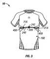
本発明の例示的な実施形態において、センサ衣服10が提供される。センサ衣服10は、布地部分100、ハーネス200及び装置保持要素300を含み得る。いくつかの例示的な実施形態において、センサ衣服10は、少なくとも1つのセンサ400を含む。図1〜8、11、12、24、25、29〜33及び35〜46は、本発明の例示的な実施形態に従ったセンサ衣服10を図示する。 In an exemplary embodiment of the invention, a
センサ衣服10は、着用者によって着用されるように適合され得る。センサ400は、ハーネス200の端部に位置して良いが、着用者の生理学的特性またはパフォーマンス特性を感知し得る。生理学的特性は、着用者の体の状態を示し得る(例えば心拍数、体温、呼吸速度、水分補給状態)。パフォーマンス特性は、目的のパラメータに関する着用者の体のパフォーマンスを示し得(例えば速度、向き、方向、加速、位置、疲労、衝撃、効率)、生理学的特性を考慮に入れても良い。更に、センサ400は、ハーネス200経由で、これらの特性を示すデータをハーネス200の端部に位置するモニター装置500に送信し得る。 The
モニター装置500は、データを受信可能な任意の装置であって良い。モニター装置500は、様々な操作を実行し得る。例えば、モニター装置500は、受信したデータを保存し、それを処理し、またはそれを受信装置に送信しても良い。いくつかの例示的な実施形態において、モニター装置500及び受信装置は、それぞれ、共同所有の米国特許出願番号号(代理人整理番号2483.187000、発明の名称:グループパフォーマンスをモニタリングするシステム及び方法)に開示された個体モニター及びベースステーションのようなものであり、この開示内容は、その全体を引用することによって本明細書の一部となす。いくつかの例示的な実施形態において、モニター装置500は、着用者の相当な不快感や動作の制限を引き起こさずに、センサ衣服10の装置保持要素300を介して着用者が容易に携帯するのに十分なだけ小さい。The
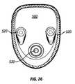
いくつかの例示的な実施形態において、図26〜28の例示的な実施形態に示されるように、モニター装置500はポッドのような装置であって良く、ユニバーサル・シリアル・バス(USB)ポート510と、少なくとも1つのデータポート520と、表示部及び/またはコントロール530と、を含み得る。モニター装置は、電池、位置モジュール、心拍数モニターモジュール、コントローラー、ユーザーインターフェース、トランシーバー、アンテナ、加速センサモジュール、メモリ、ジャイロスコープモジュール、磁力計モジュール、呼吸モジュール、光センサモジュール、及び温度センサモジュールのうちの少なくとも1つを更に含み得る。モニター装置500は、それ自体がこれらのモジュールに対応するセンサを含んでも良く、またはハーネス200を介して異なる複数のセンサ400に接続されても良い。本明細書に記載のセンサ及び対応するモジュールは単に例示的なものであり、その他のセンサ及びモジュールも本発明の実施形態と共に使用できる。電池は、モニター装置500に電力を供給し得る。 In some exemplary embodiments, as shown in the exemplary embodiments of FIGS. 26-28, the
データポート520は、モニター装置500への、及びモニター装置500からの情報転送を促進し得、後述のハーネス200の導電性要素210の終端点に接続し得る。データポート520は、導電性要素210に接続するための任意の好適な接続部を含み得る。いくつかの例示的な実施形態において、データポート520は、個々に導電性要素210に接続するように構成された1つ以上の端子(terminal)を含む。いくつかの例示的な実施形態において、データポート520はユニバーサル・シリアル・バス(USB)ポートであって良い。いくつかの例示的な実施形態において、モニター装置500のトランシーバーは、データ送信/受信能力を含んでいて良く、単一の部品または別個の複数の部品を含んでいて良い。図26〜28の例示的な実施形態において、モニター装置500はポッドのような装置として図示されている。しかし、モニター装置500は、例えばスマートフォン、携帯電話、電子書籍リーダー、PDA(個体用デジタル補助装置)、またはデータの受信及び送信ができるその他の類似の装置等、任意のその他の好適な装置であって良い。 The
使用の際、着用者は、運動活動に従事するアスリートであって良いが、パフォーマンスをモニターする(または別の者がモニターすることを容易にする)ためにセンサ衣服10を着用し得る。このようなパフォーマンスを示す生理学的特性及びパフォーマンス特性のデータは、センサ400において受信され、装置保持要素300に保持されるモニター装置500に(ハーネス200経由で)送信され、モニター装置500によって離れた受信装置に送信され得る。 In use, the wearer may be an athlete engaged in athletic activity, but may wear the
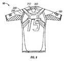
1つの実施形態において、センサ衣服10はシャツ(図面に示すような)を含み得る。いくつかの例示的な実施形態において、センサ衣服10は、例えばベスト、コンプレッションシャツ、サスペンダー、バンド、ストラップ、ショルダーハーネス、圧縮ベース層を有するシャツ、ジャージ、タンクトップ、ブラジャー、スリーブ、アームバンド、ヘッドバンド、帽子、チューブ・トップ、ショーツ、ブリーフ、パンツ、靴下、ジャケット、上着、水着、ウエットスーツ、並びにその他の好適な衣服または衣料及びその一部等の衣服を含み得る。1つの実施形態において、センサ衣服10の1つ以上の特徴がフットウェアに取り入れられて良い。いくつかの例示的な実施形態において、センサ衣服10は、その上に別の衣服を着用すること無く着用するように設計されている。いくつかの例示的な実施形態において、センサ衣服10は、例えば図9及び10に示すようなジャージ20のような別の衣服を衣服10の上に着用しつつ着用するように設計されている。 In one embodiment,
布地部分100は、センサ衣服10の形を形成してそれに適合して良く、着用者の体の任意の部分に適合するように設計されて良い。いくつかの例示的な実施形態において、着用者は人間であるが、本発明の実施形態は、人間ではない生物にも同様に適用できる。いくつかの例示的な実施形態において、布地部分100は、着用者の体にぴったりとフィットするように設計される(すなわち、布地部分100の内側表面が、予期される体の動作を通して着用者の体に接触するように設計される)。最適な、または所望のフィット感をサポートするために、布地部分100は、弾性部分と共に非弾性部分も含み得る。 The
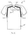
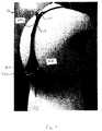
図2を参照すると、布地部分100は、データを受信して(ハーネス200経由で)データを受信装置に送信することができるモニター装置500のような装置を保持するように構成された装置保持要素300を含み得る。いくつかの例示的な実施形態において、装置保持要素300は、センサ衣服10の着用者の動きのモニター装置500への影響を最小限にするために、モニター装置500を中に入れて適所に保持できるように、モニター装置500の大きさ及び形に対応する大きさ及び形にする。後で更に詳しく述べるが、こうした影響を最小限にするのを助けるために、例えばバンド312やスペーサー要素340等の追加的な要素を使用できる。図2に示すように、装置保持要素300は布地層100とつながっていて良い。図2は、布地層100とつながっている装置保持要素300を含むセンサ衣服10の例示的な実施形態を図示する。装置保持要素300は、例えば一体化する、接着する、縫い合わす、溶着する、結ぶ、挟む、留める、または取り付ける、あるいはこれらやその他の技術の任意の組み合わせにより布地層100とつながっていて良い。いくつかの例示的な実施形態において、装置保持要素は布地層100と一体化して形成される(例えば、布地層100を縫い合わせるまたは編むことによりポケットを形成しても良い)。 Referring to FIG. 2, the
図2の例示的な実施形態において、装置保持要素300は、布地層100の外側上に配置された開口部320を有する織物層によって形成されたポケットである。いくつかの例示的な実施形態において、装置保持要素300は、布地層100の内側上に配置された開口部320を有する織物層によって形成されたポケットである。いくつかの例示的な実施形態において、装置保持要素300は、布地層100の内側上に配置された開口部320を有さない織物層によって形成されたポケットである。このような実施形態において、布地層100は、布地層100の外側からのポケットへのアクセスを提供する開口部320を含み得る。いくつかの例示的な実施形態において、装置保持要素300は、布地層100の外側または内側に取り付けられた、あるいはそこに一体化された完全なポケットである。いくつかの例示的な実施形態において、装置保持要素300は、織物で形成されるよりも、少なくとも一部がその他の材料、例えばプラスチック、ゴム、熱可塑性ポリウレタン、またはネオプレン等で形成される。 In the exemplary embodiment of FIG. 2, the
図2の例示的な実施形態において、装置保持要素300は、センサ衣服10の着用者の背中上部に対応するように配置される。装置保持要素300を着用者における高い位置、例えば背中上部等に対応するように配置することは、モニター装置500がデータを送信または受信する際に、装置保持要素300内のモニター装置500の干渉を最小限にし、範囲及び信号強度を最大限にするのに役立ち得る。加えて、装置保持要素300を背中上部に対応するように配置することは、装置保持要素300(及びそれにより保持されるモニター装置500)によるアスリートの動きへの干渉を最小限にする。いくつかの例示的な実施形態において、装置保持要素300は、着用者の背中上部以外に対応するように配置される。装置保持要素300は、布地層100上の任意の場所に配置できる。例えば、装置保持要素300は、着用者の背中下部、胸部、横腹、肩、腕、脚、臀部、足、首または頭に対応するように配置しても良い。 In the exemplary embodiment of FIG. 2, the
いくつかの例示的な実施形態において、装置保持要素300はポケット以外のものである。例えば、装置保持要素は、マウント、スナップ、ひも、ボタン、格子(lattice)、またはクリップを含み得る。装置保持要素300は、様々な方法でモニター装置500を保持して良く、例えば、モニター装置500は、装置保持要素300内に配置されたり、装置保持要素につながれたり、装置保持要素からぶら下げたり、あるいは装置保持要素内に取り付けたりして良い。装置保持要素300は、図2に示すように布地層100の外側上に配置されて良い。いくつかの例示的な実施形態において、装置保持要素300は、布地層100の外側上以外に配置される。例えば、装置保持要素300は、布地層100の内側上に配置したり、布地層100と一体化させても良い。いくつかの例示的な実施形態において、布地層100は複数の層を含む。このような実施形態において、装置保持要素300は、布地層100の層と層の間、外側層または内側層の上面上、あるいは、外側層または内側層の底面上に配置して良い。図13、15及び20〜23は、後で述べるような装置保持要素300の更なる例示的な実施形態を図示する。 In some exemplary embodiments,
図2に示すように、例えば、装置保持要素300は、モニター装置500の挿入及び取り外しのための開口部320を含み得る。いくつかの実施形態において、開口部320は、例えばジッパー、面ファスナー、ひも、スナップ、ボタン、またはその他の好適な閉じ要素によって閉めることができる。装置保持要素は穴330を含み得、これは、装置保持要素300によって保持されている間、モニター装置500の一部を見るための窓を提供し得る。例えば、モニター装置500が表示部及び/またはコントロール530(例えばLCD(液晶表示)、LED(発光ダイオード)表示、個々のLED、電子インク、スイッチ、またはボタン)を含む場合、穴330は表示部及び/またはコントロール530へのアクセスを提供し得る。 As shown in FIG. 2, for example, the
装置保持要素300は、図2の例示的な実施形態におけるもののような支持要素310を含み得、これは、例えば、動きに対する耐性の増加、安定性の増加、及び耐摩耗性の増加により、装置保持要素300の支持を提供し得る。支持要素310はまた、装置保持要素300内における、またはそれに対するモニター装置500の位置を維持するのに役立ち得る。 The
図2の例示的な実施形態において、支持要素310は、装置保持要素300の外側表面上にパターン形成されたTPU(熱可塑性ポリウレタン)層である。このような支持要素310は、装置保持要素300上に、またはその中に積層され得る。いくつかの例示的な実施形態において、支持要素310は、装置保持要素300上にプリントされて良く、または装置保持要素300に一体化された弾性の(例えばゴムの)バンドであっても良い。図2において、支持要素310は、開口部320の周囲の領域を特に支持する。これは、モニター装置500を繰り返し挿入したり取り出したりする結果生じ得る開口部320の周囲の摩耗を最小限にするのに役立ち得る。支持要素310は、図2の例示的な実施形態のように、装置保持要素300の縦部分を特に支持する縦バンド312を含み得る。これは、モニター装置500の縦方向の動きを最小限にするのに役立ち得、それは、着用者の運動活動中、例えばランニング等による相当な縦方向の力がモニター装置500にかかる場合に望ましいものであり得る。支持要素310は、開口部320の周囲に配置される開口部支持要素314を更に含み得、これは、支持を提供し、及び/またはその領域へのアクセスを容易にし得る。 In the exemplary embodiment of FIG. 2, the
図2の例示的な実施形態において、支持要素310は、装置保持要素300の外側表面を部分的に覆うのみである。いくつかの例示的な実施形態において、支持要素310は、装置保持要素300の外側及び/または内側表面を完全に覆う。 In the exemplary embodiment of FIG. 2, the
装置保持要素300は、様々な実施形態に従って提供され得る。1つの例示的な実施形態において、図13に示すように、装置保持要素300は、スペーサー要素340を含むポケットを含み得る。これについては後でより詳しく述べる。1つの例示的な実施形態において、図15に示すように、装置保持要素300は、そこを通してモニター装置500を受け入れるための細長い開口部としての開口部320と、例えば図26に示す表示部及び/またはコントロール530のようなモニター装置500の特徴に対応するように構成された1つ以上の穴330と、を含むポケットを含み得る。1つの例示的な実施形態において、図20に示すように、装置保持要素300は、モニター装置の特徴を見せるような大きさ及び配置にされた開口部320を含むポケットを含み得る。図20の例示的な実施形態において、装置保持要素300は穴330を含まない。1つの例示的な実施形態において、図21に示すように、装置保持要素300は、モニター装置500を適所に保持するように構成された弾性バンド350を含み得る。図21の例示的な実施形態において、弾性バンド350のバンド間のスペースは穴330の役割を果たし得る。1つの例示的な実施形態において、図22に示すように、装置保持要素300はひも360を含み得る。図22の例示的な実施形態において、モニター装置500は複数のひも360の間の開口部320を通じて挿入でき、装置保持要素300内にモニター装置500が所望の通りぴったりフィットするように、ひもを締めたり緩めたりできる。1つの例示的な実施形態において、図23に示すように、装置保持要素300は網状の覆い370を含み得、これは、開口部320を通じた装置保持要素300の側面へのアクセスを提供する。 The
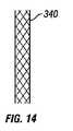
センサ衣服10は、運動活動のセッション中にアスリートによって着用され得る。このような活動中、装置保持要素300に保持されるモニター装置500は、アスリートの動きにより様々な種類の入射力にさらされ得る。いくつかの例示的な実施形態において、装置保持要素300はスペーサー要素340を含み、これは、モニター装置500と着用者の間の詰め物を提供し、モニター装置500の動きを抑制及び制御するのを助け、モニター装置500への衝撃及び/またはせん断力を減じ、モニター装置500において、またはその近くに衝撃があった場合の着用者の怪我を最小限にとどめることができる。図13及び14に示すように、いくつかの例示的な実施形態において、装置保持要素300がポケットである場合、スペーサー要素340は、ポケットの内側またはポケット上に配置され得、例えば、ポケットの内側領域とセンサ衣服10の着用者との間に配置されるように構成される。スペーサー要素340は、少なくとも片面が布地層100とつながっていて良い。スペーサー要素340は、立体的なメッシュまたは発泡体であって良く、せん断力を抑制し、それによりモニター装置500への入射力を最小限にし、衣服10の着用者の不快感を最小限にすることができる。 The
いくつかの例示的な実施形態において、モニター装置500は、センサ400からデータを受信するように構成され、センサ400は、モニター装置500内に含まれても良く、または、モニター装置500から分離した異なるものであっても良い(例えば布地層100またはセンサ衣服10の着用者とつながっている)。いくつかの例示的な実施形態において、例えば図3及び4に図示するもののように、例えば、センサ衣服10は、センサ衣服10の着用者の背中上部に配置されモニター装置500を保持するように構成された装置保持要素300を含み得、着用者の胴体の側面に近接して配置されるように構成されたセンサ400を含み得る。センサ衣服10は、所望するだけの、または必要なだけの任意の好適な数または種類のセンサ400を含み得る。例えば、センサ衣服10は、着用者の心拍数(例えばECG(心電計)信号)、呼吸速度、体温、位置、加速、距離、向き、速度、方向、方角、酸素レベル、または水和反応を検出するように構成されたパフォーマンスセンサ400、生理学的センサ400、またはその他のセンサ400を含み得る。このようなセンサ400は、例えば電極、心拍数モニター(例えばECGセンサ)、磁力計、呼吸センサ、光センサ(例えば着用者の環境に関する情報を提供する、またはそれと相互作用する)、圧力センサ(例えば衝撃または衝突を測定する)、熱電温度計、GPS(全地球測位システム)センサ、反響定位センサ、RFID(無線自動識別)センサ、ビーコンセンサ、加速度計、ジャイロスコープ、コンパス、生体力学的センサ、任意のその他の好適なセンサ、あるいはそれらの任意の組み合わせを含み得る。 In some exemplary embodiments, the
生体力学的センサは、例えば図47に示すように、伸縮性導電性要素415を有する伸縮センサ405(例えば広い反射領域を有し得る着用者の体の一部、例えば肘、膝、肩または足等に対応するように構成された領域においてセンサ衣服10から分離している、またはそこに含まれる)を含み得る。伸縮性導電性要素415は、例えば、伸縮性ワイヤー(例えば弾性核の周囲に巻かれるワイヤー)、例えばジグザグ、正弦曲線、またはループのパターンの伸縮性パネルに含まれる非伸縮性ワイヤー、あるいは導電性ポリマー、あるいは導電性布であって良く、後で更に詳細を述べる。伸縮性導電性要素415の変形は、伸縮性導電性要素415の抵抗の変動に基づいて感知され得、着用者の体の動き(例えば動きの発生、大きさ、速度または方向)の決定に使用され得る。いくつかの例示的な実施形態において、このような抵抗の変動は、伸縮性導電性要素415に隣接して配置され直接取り付けられる抵抗センサ/フィルター425において感知され、ハーネス200経由でモニター装置500に伝えられる。 The biomechanical sensor is, for example, as shown in FIG. 47, a
例示的なセンサ400及びその潜在的使用の更なる例は、共同所有の米国特許出願番号号(代理人整理番号2483.187000、発明の名称:グループパフォーマンスをモニタリングするシステム及び方法)において見ることができ、この開示内容は、その全体を引用することによって本明細書の一部となす。いくつかの例示的な実施形態において、センサ400は、センサ衣服10の一部を形成しても良く、布地層100内に一体化されてもそれに取り付けられても良い。いくつかの例示的な実施形態において、センサ400は、センサ衣服10から分離してそこにつなげられるように適合されても良い。いくつかの例示的な実施形態において、センサ400は受信器であって良く、離れているセンサまたは送信器からの信号を受信するためのアンテナ450の役割を果たし得る。例えば、そのような実施形態において、受信器は、着用者が飲み込んだ中核体温センサからの信号を受信するように構成されても良く、例えば図43に示すように、脊椎からはずれた着用者の背中の中心に対応するように配置して良い。いくつかの例示的な実施形態において、センサ400は、例えば図38に示すように、スピーカー及び/またはマイクロホン460を含むか、またはそれにつながれて良い。スピーカー及び/またはマイクロホン460は、離れた装置及びモニター装置500との間で音声情報を送信または受信し得る。スピーカー及び/またはマイクロホン460は、センサ衣服10の着用者と着用者から離れている人物との間の通信を可能にし得る。A further example of
アンテナ450は、モニター装置500から分離していてもそこに一体化していても良い。アンテナ450がモニター装置500から分離している実施形態において、アンテナ450は布地層100につながれていて良い。アンテナ450は、例えばモニター装置500と離れているセンサまたは送信器との間で信号を無線で送信及び受信することにより、これらの要素間の通信を容易にするように構成されて良い。アンテナ450は、例えば巻かれたまたは包まれた導線、導電性布、導電接着剤、導電糸、導電性ポリマー、またはプラスチック上にプリントされた銀インクで形成されて良い。いくつかの例示的な実施形態において、アンテナ450は、保持要素によって布地層100(またはセンサ衣服10の任意の部分)につなげられ、保持要素は、例えば本明細書に記載の装置保持要素300に類似のものであって良い。いくつかの例示的な実施形態において、アンテナ450は、縫い付けられる、積層される、接着される、超音波によって接着される、またはプリントされることにより、布地層100(またはセンサ衣服10の任意の部分)につなげられる。いくつかの例示的な実施形態において、詰め物がアンテナ450に近接して含まれ、この詰め物は、アンテナ450を保護し、センサ衣服10の着用者の不快感を減じ得る。詰め物は、例えばスペーサー要素340の材料(本明細書に記載)、またはポリマー(例えば柔らかいシリコーン)等の任意の好適な詰め物であって良い。 The antenna 450 may be separated from the
センサ400は、その種類によっては、センサ衣服10の着用者の肌に接触するように構成されるようにセンサ衣服10内に配置されても良い。いくつかの例示的な実施形態において、センサ400の少なくとも一部は、着用者の体に対するセンサ衣服10の残りの部分の動きから分離している。活動中に着用者の体が動くと、それに応じてセンサ衣服10の全部または一部が動く。着用者の体に対するセンサ400の一部の望ましくない動きを最小限にするために、センサ400の一部を、後で述べるように、ハーネス200とセンサ400の一部の間の相対的な動きを可能にする技術を用いて、着用者の体に固定し、ハーネス200につなげるようにしても良い。センサ400の少なくとも一部が布地層100とは対照的に着用者の体に固定されるので、センサ400の一部は衣服の動きにさらされないでおける。これは、確実で一貫した肌への接触及び着用者に対するポジショニングの維持の助けとなり得る。例えば、いくつかの例示的な実施形態において、センサ400は、ぶら下げることによりセンサ衣服10の残りの部分(例えばハーネス200)につながれる。ぶら下がっているセンサ400は、ハーネス200への接続(例えば延長ワイヤー接続)においていくらかのたるみを有しても良く、それにより、センサ400とハーネス200の間の相対的な動きを可能にする。ぶら下がっているセンサ400は、例えば吸着力、テープ、または粘着性物質により着用者の肌につなげても良い。この方法において、いくつかの実施形態においては、センサ400の一部はセンサ衣服10の動きに対して固定されて良く(そして着用者の体に対して動いて良く)、また、センサ400の一部はセンサ衣服10に対して動いても良く(そして着用者の体に対して実質的に固定されても良い)。 Depending on the type, the
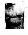
いくつかの例示的な実施形態において、センサ400は、例えば図24、25、40及び41に示すようにバンド420に組み込まれ、これは弾力性を有し、着用者の胸部またはその他の解剖学的特徴を囲むように構成されても良い。図24、25、40及び41の例示的な実施形態において、センサ衣服10は図示しやすいように裏返しに示している。いくつかの例示的な実施形態において、このようなバンド420は布地層100に取り付けられて良い(例えば、センサ400はセンサ衣服10の内側支持層(例えばバンド420)に取り付けられて良く、これは、例えば図40に示すように布地層100と一体化させても良く、または例えば図41に示すように別々のポイントにおいて布地層100に取り付けられても良い)。いくつかの例示的な実施形態において、このようなバンド420は布地層100から独立していて良い(例えば、センサ400は、布地層100の下に着用できるブラジャーのような衣服に一体化させても良く、そのセンサは、ハーネス400につながるように構成されて良い)。 In some exemplary embodiments, the
センサの種類、衣服の種類、美的感覚、及び製造の考慮を含む様々な要因によっては、センサ400は、装置保持要素300に対して様々な位置に配置されて良く、布地層100上またはその中(例えば着用者の胴体、背中、横腹、腕または首に対応するように構成された布地層の領域上)の、あるいはそこから離れた任意の好適な位置に配置されて良い。いくつかの例示的な実施形態において、モニター装置500が装置保持要素300によって保持されている場合、センサ衣服10は、センサ400を装置保持要素300及びモニター装置500に接続するためのハーネス200を含む。 Depending on a variety of factors, including sensor type, clothing type, aesthetics, and manufacturing considerations, the
ハーネス200は、図1に示すように、例えばデータを電子的に通信できる導電性要素210と、ハーネスガイド部分220と、を含み得る。導電性要素210は、例えば図3及び4に示すように1つまたは複数の終端点を含み得る。例えば、導電性要素210は、第1終端点212、第2終端点214及び第3終端点216を含み得る。これらの終端点の構成は、後で述べるように様々であって良い。ハーネスガイド部分220は、例えば図17に示すように複数の層を含み得る。例えば、ハーネスガイド部分220は、後で述べる第1層222、第2層224及び織物層226を含み得る。いくつかの例示的な実施形態において、導電性要素210は、ハーネスガイド部分220の層と層の間に配置される。 As shown in FIG. 1, the
いくつかの例示的な実施形態において、ハーネス200は、衣服10の布地層100の表面と一体化して、またはその上に配置されて良い。図1の例示的な実施形態において、センサ衣服10は図示しやすいように裏返しに示している。このように、通常の使用においては、図1の例示的な実施形態のハーネス200は、センサ衣服10の布地層100の内側表面上に配置されることになる。いくつかの例示的な実施形態において、ハーネス200は、布地層100の内側表面上またはそれに隣接して配置されても、布地層100の外側表面上またはそれに隣接して配置されても、布地層100と一体化されても良い。ハーネス200は、例えば接着剤、縫い付け、溶着や積層を含む任意の好適な技術によって布地層100につながれて良い。図面全体を通じて、センサ衣服10は裏返しまたは裏返しではなく図示されていると解釈できる。 In some exemplary embodiments, the
導電性要素210は、例えば図29に示すようにセンサ400と、そしてモニター装置500と接続するように構成されても良く、データをセンサ400からモニター装置500に送信するように構成されても良い。これを達成するために、導電性要素210は、センサ400及びモニター装置500に対応する終端点を含み得る。例えば図3、4及び34に示すように、導電性要素210は、モニター装置500に接続するように構成された第1終端点212と(例えば図4、6、8及び12参照)、センサ400に接続する第2終端点214と、別のセンサ400に接続する第3終端点216と、を含み得る。各終端点は、終端点における導電性要素210の構成に応じて単一または複数の端子接続を含み得る。終端点が複数の端子接続を有する場合、これらの接続には、追加の部品との適切な接続を容易にするためにラベルを付けても良い。例えば、モニター装置500に接続するように構成された終端点は、センサ衣服10のそれぞれ左と右に配置されるセンサに対応することを示す「左」及び「右」のラベルが付けられた2つの端子接続を含み得る。ハーネス200の導電性要素210は、センサ400及びモニター装置500の配置に適合する任意の好適な数及び配置の終端点を含み得る。 The
ハーネス200のガイド部分220は、例えば図1、3及び4の例示的な実施形態に示すように、終端点と終端点の間で導電性要素210をガイドし得る。いくつかの例示的な実施形態において、ガイド部分220は、第1層222及び第2層224から形成され、第1層222及び第2層224は、例えば図17の例示的な実施形態に示すように、間に導電性要素210をはさんでつながれるように構成される。いくつかの例示的な実施形態において、第1層222及び第2層224のうちの片方または両方が接着性層である。いくつかの例示的な実施形態において、ハーネス200は、ガイド部分220につながっている織物層226を含む。織物層224は、弾性を有し、センサ衣服10の内側に対応するように配置して良く、それによりハーネス200が原因の着用者の不快感を減じることができる。 The
いくつかの例示的な実施形態において、例えば図3及び4に示すように、ハーネス200は、布地層100に直接固定された第1ハーネス部分230と、布地層100への固定から少なくとも部分的に自由な第2ハーネス部分240と、を含む。第2ハーネス部分240は、「ブリッジ」と呼ばれ得る。いくつかの例示的な実施形態において、布地層100に対する第2ハーネス部分240の動きは、布地層100に取り付けられ第2ハーネス部分240の周りをループするループ242によって制約され得る。第2ハーネス部分240は、ハーネス200の直接固定への導電性を有さないセンサ衣服10の領域にわたってのセンサ400とモニター装置500間の通信を可能にするために特に有用であり得る。例えば、いくつかの例示的な実施形態において、ハーネス200は、布地層100が弾性を有する領域における布地層100への直接固定に最適であり得る。センサ衣服10の柔軟性のない部分の異なる側に配置されたセンサ衣服10の要素と要素の間の接続を維持するために、ハーネス200は、例えばセンサ衣服10の柔軟性のない部分をブリッジするための第2ハーネス部分240を含んで良く、それにより、センサ衣服10の柔軟性のない領域に直接固定する必要無しに、センサ衣服10の要素を接続することができる。センサ衣服10の布地層100は、所望のフィット感及び美的感覚を得るため、または、例えばチームのジャージにおけるチームロゴ、スポンサーロゴやプレイヤーの番号等のグラフィックが歪まないようにするために、柔軟性のある、及び柔軟性のない材料のパネルを含んでいて良い。 In some exemplary embodiments, as shown, for example, in FIGS. 3 and 4, the
ハーネス200の経路は、様々な必要条件や所望事項に適合するように構成されて良い。例えば、いくつかの例示的な実施形態において、ハーネス200は、グラフィックやプリントの美的感覚や製造における妨げにならないよう、そのようなグラフィックやプリントを含まない、または含む予定の無いセンサ衣服10の領域のみをカバーするように経路が設定されて良い。 The path of the
いくつかの例示的な実施形態において、第2ハーネス部分240は、そのようなグラフィックやプリントの上を「ブリッジ」しても良い。いくつかの例示的な実施形態において、ハーネス200は、例えば製造を単純化したりセンサ衣服10の耐久性を維持したりするために、センサ衣服10の継ぎ目を横断したり妨げたりしないように経路が設定されて良い。いくつかの例示的な実施形態において、ハーネス200は、センサ衣服10の継ぎ目に組み込まれたり、あるいは継ぎ目に沿って伸びても良い。 In some exemplary embodiments, the
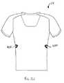
いくつかの例示的な実施形態において、例えば図3、4、11及び12に示すように、ハーネス200は、着用者の背中上部に配置されるように構成された第1終端点212から背中を下り、センサ衣服10の片側を回って、着用者の一方の側に配置されるように構成された第2終端点214に到達し、センサ衣服10の前面を横切って、着用者のもう一方の側に配置されるように構成された第3終端点216まで伸びる。 In some exemplary embodiments, as shown, for example, in FIGS. 3, 4, 11 and 12, the
いくつかの例示的な実施形態において、例えば図5〜8に示すように、ハーネス200は、着用者の背中上部に配置されるように構成された第1終端点212から肩の後ろに沿って伸び、センサ衣服10の片側を回って、着用者の一方の側に配置されるように構成された第2終端点214に到達し、センサ衣服10の前面を横切って、着用者のもう一方の側に配置されるように構成された第3終端点216まで伸びる。 In some exemplary embodiments, as shown, for example, in FIGS. 5-8, the
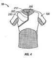
いくつかの例示的な実施形態において、例えば図1、24及び25に示すように、ハーネス200は、着用者の背中上部に配置されるように構成された第1終端点212からセンサ衣服10の肩領域の上を通ってセンサ衣服10の前面まで伸び、先が分かれて、着用者のそれぞれの側に配置されるように構成された終端点214及び216に到達する。 In some exemplary embodiments, as shown, for example, in FIGS. 1, 24, and 25, the
いくつかの例示的な実施形態において、例えば図45及び46に示すように、ハーネス200は、着用者の背中上部に配置されるように構成された第1終端点212から背中を下り、そこで2つの部分に分かれてセンサ衣服10のそれぞれの側を回って伸び、一方の部分が、着用者の一方の側に配置されるように構成された第2終端点214まで伸び、もう一方の部分が、着用者のもう一方の側に配置されるように構成された第3終端点216まで伸びる。 In some exemplary embodiments, as shown, for example, in FIGS. 45 and 46,
いくつかの例示的な実施形態において、例えば図30及び31に示すように、ハーネス200は、装置保持要素300の左側及び右側に配置される2つの第1終端点212のそれぞれから2つの部分のそれぞれが伸びる。装置保持要素300は、センサ衣服10の背中上部領域に配置して良い。ハーネス200の一方の部分は、左肩の後ろに沿って伸び、左腕の下を通って第2終端点214まで伸びて良く、もう一方の部分は、右肩の後ろに沿って伸び、右腕の下を通って第3終端点216まで伸びて良い。 In some exemplary embodiments, for example, as shown in FIGS. 30 and 31, the
いくつかの例示的な実施形態において、例えば図47に示すように、ハーネス200は、装置保持要素300の左側及び右側に配置される2つの第1終端点212のそれぞれから2つの部分のそれぞれが伸びる。装置保持要素300は、センサ衣服10の背中上部領域に配置して良い。ハーネス200の一方の部分は、左肩の後ろに沿って、そして左腕に沿って、センサ衣服10の左肘領域に配置される第2終端点214まで伸びて良く、もう一方の部分は、右肩の後ろに沿って、そして右腕に沿って、センサ衣服10の右肘領域に配置される第3終端点216まで伸びて良い。 In some exemplary embodiments, for example, as shown in FIG. 47, the
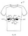
いくつかの例示的な実施形態において、例えば図35に示すように、ハーネス200は、装置保持要素300の左側及び右側に配置される2つの第1終端点212のそれぞれから2つの部分のそれぞれが伸びる。装置保持要素300は、2つのセンサ400の間にあるセンサ衣服10の前面中央領域に配置して良い。ハーネス200の一方の部分は、左側を第2終端点214まで伸びて良く、もう一方の部分は、右側を第3終端点216まで伸びて良い。 In some exemplary embodiments, for example, as shown in FIG. 35, the
いくつかの例示的な実施形態において、例えば図36に示すように、ハーネス200は、装置保持要素300の左側及び右側に配置される2つの第1終端点212のそれぞれから2つの部分のそれぞれが伸びる。装置保持要素300は、2つのセンサ400の間にあるセンサ衣服10の後面中央領域に配置して良い。ハーネス200の一方の部分は、右側を第2終端点214まで伸びて良く、もう一方の部分は、左側を第3終端点216まで伸びて良い。 In some exemplary embodiments, for example, as shown in FIG. 36, the
いくつかの例示的な実施形態において、例えば図37に示すように、ハーネス200は、装置保持要素300に配置される第1終端点212から伸びる。装置保持要素は、センサ衣服10のサイド領域に配置されて良い。ハーネス200は、センサ衣服10の前面の一方の側の第2終端点214まで伸び、第2終端点214からセンサ衣服10の前面を横切って、センサ衣服10の前面のもう一方の側の第3終端点216まで伸びて良い。 In some exemplary embodiments, for example, as shown in FIG. 37, the
ハーネス200の形及び経路は、モニター装置500やセンサ400の様々な位置を含む多様な特別の必要条件や所望事項に適合するように、変化させて良い。例えば、着用者の前部またはサイドにおけるセンサ400へ経路を定めるよりも、ハーネス200は、着用者の胸部または背中に配置されたセンサ400(例えば、着用者の胸部の真ん中に配置されるように構成された心拍数センサ)に対応するように、着用者の胸部または背中領域へ経路を定めても良い。いくつかの例示的な実施形態において、例えば図1、5及び30に示すように、センサ400は、着用者の前部に位置する着用者のサイド領域に対応するように配置される。いくつかの例示的な実施形態において、例えば図32及び33に示すように、センサ400は、センサ衣服10の最端のサイド領域に配置される。いくつかの例示的な実施形態において、例えば図36に示すように、センサ400は、センサ衣服10の後面のサイド領域に配置される。 The shape and path of the
センサ400は、様々な必要条件や所望事項に適合するように、様々な形及び大きさを有して良い。いくつかの例示的な実施形態において、複数のセンサ400のうちのいくつかまたは全ての動作については、着用者の肌への接触が有効であり得る。そのような例示的な実施形態において、センサ400は、接触させることを意図する着用者の肌の特定の領域の解剖学的形及び大きさに対応するような形及び大きさにできる。いくつかの例示的な実施形態において、肌への接触を最適にするために、センサ400は、ブラシのようなセンサであったり(例えばセンサ400への潜在的な接触ポイントを複数提供するための、センサから伸びる複数の接触要素を有するセンサ)、支えられていたり(例えば、センサと布地層100の間の裏当て材によって支持されたセンサであって、裏当て材により、センサが着用者の肌に対して布地層から伸びやすいようになり、裏当て材は、例えばスペーサー要素340の材料や、眠るときの枕によく使用される厚く弾力のあるポリエステル繊維充填材であって良い)、または粘着性のある領域を含んでいて良い(例えば、センサ400の周囲が粘着性を有する)。いくつかの例示的な実施形態において、センサ400の肌への接触を最適にするために、布地層100の内側表面は、付着するセンサ400の周囲に粘着性を有する領域を含んで良く、または、着用者の肌に自然に付着するように構成されたセンサ400の周囲の領域を含んでも良い(例えばシリコーンのパネル)。いくつかの例示的な実施形態において、センサ衣服10は、センサ衣服10(例えばコンプレッションシャツ)のタイトフィットにより、センサ400と着用者の肌の間の接触を維持するように構成される。いくつかの例示的な実施形態において、いくつかまたは全てのセンサ400は着用者の肌と接触する必要がなく、肌と接触しないように配置されて良い。 The
ハーネス200は、使用中に変形や伸びを引き起こす力にさらされても良い。ハーネス200は、伸縮性を有し、そのような力を弾性的に受け入れることができるように、弾性材料でできていて良い。例えば、第1層222、第2層224及び織物層226の各々は、弾性材料でできていて良い。また、いくつかの例示的な実施形態において、導電性要素210は弾性を有していて良い。ハーネス200は、例示的な実施形態に従い、伸縮性、耐久性及び応力解放性を発揮する。当業者には明らかになるであろうが、これらの特性は、様々な必要条件や適用に合わせて調節したり最適化したりできる。いくつかの例示的な実施形態において、ハーネス200は、布地層100と実質的に同等の弾性を有する。いくつかの例示的な実施形態において、ハーネス200は、布地層100よりも大きな弾性を有する。いくつかの例示的な実施形態において、ハーネス200は、布地層100よりも小さな弾性を有する。いくつかの例示的な実施形態において、ハーネス200は、着用者の体に適合するのに十分な弾性を有し、それによりセンサ400の着用者の体との接触を促進する。 Harness 200 may be exposed to forces that cause deformation and elongation during use. The
いくつかの例示的な実施形態において、ハーネス200は、着用者によるセンサ衣服10の着脱により生じる伸張に耐えるのに十分な弾性を有する。いくつかの例示的な実施形態において、ハーネス200は、どの方向にも変形したままになること無く、伸びていない時の長さの20〜100%まで伸びるように構成される。いくつかの例示的な実施形態において、ハーネス200の異なる部分はそれぞれ、変形したままになること無く、伸びていない時の長さの異なる割合まで伸びるように構成される。例えば、センサ衣服10の襟足の周囲に配置されるハーネス200の一部は、伸びていない時の長さの20〜30%まで伸びるように構成されて良く、一方で、ハーネス200のY字型のネック等の部分や、センサ衣服10の胸部や胴体中程の領域に配置されたハーネス200の一部は、80〜100%まで伸びるように構成されて良い。いくつかの例示的な実施形態において、ハーネス200の一部は、垂直方向よりも体を横切る方向により長く伸びるように構成されて良く、その逆でも良い。 In some exemplary embodiments, the
いくつかの例示的な実施形態において、布地層100は、着用者の体に適合するのに十分な弾性を有し、それによりセンサ400の着用者の体との接触を促進する。いくつかの例示的な実施形態において、布地層100は、布地層100の他の部分よりも大きな弾性を有する部分を含み、そのより大きな弾性を有する部分は、ハーネス200が布地層100につなげられる領域に対応していて良い。いくつかの例示的な実施形態において、センサ衣服10(特に導電性要素210、粘着性第1層222、第2層224、織物層226、及び/または布地層100)の伸張及び弾性特性は、耐久性、運動の自由度、及びセンサ衣服10の着脱を促進するように構成される。 In some exemplary embodiments, the
導電性要素210は、例えば図1、17及び34示すように、導電性のワイヤーまたは糸、例えば、複数のより糸の個々に絶縁された柔軟性の高いマイクロワイヤー(例えば銀でコーティングされたナイロンや弾性核が導電性材料で囲まれた複合材料)、導電性の銀の糸、絶縁された導電性ワイヤー等が、ジグザグ、ループ、蛇行または正弦曲線のパターンに配置されたものを含み得る。柔軟性を高めるために、パターンは、導電性要素210が終端点や他のハーネス200においてより大きな伸縮性が必要または所望である場所に近づくにつれて、より小さい大きさまたはより高い頻度(例えば距離の単位毎のピークまたはループの)を採用して良く、耐久性を維持するために、ハーネス200のその他の領域においてより大きな大きさまたは頻度を維持して良い。1つの実施形態において、例えば図17及び34に示すように、導電性要素210の正弦曲線のパターンは、導電性要素210の端部近くでより高い頻度及びより小さな大きさを有して良く、導電性要素210の中間部に沿ってより低い頻度及びより大きな大きさを有して良い。より高い頻度及びより小さな大きさを有する部分は、モニター装置500またはセンサ400につなげられるように構成されたハーネス200の一部、あるいは着脱や着用において最も大きな圧力を受けるハーネス経路の領域に対応して良い。このような部分は、高められた伸縮性及びそれにより得られる張力緩和という利益を享受することができる。
センサ衣服10は、着用者の活動中に動いたり伸縮したりして良く、導電性要素210とセンサ400またはモニター装置500間の接続は圧力をかけられても良い。これらの領域において柔軟性及び弾性が高まることは、このような圧力を最小限にする助けとなり得る。より低い頻度及びより大きな大きさを有する部分は、柔軟性及び追加的要素への接続の維持の重要性がより低い、着用者の腕の下または上に配置されるように構成されたハーネス200の一部に対応して良い。1つの例示的な実施形態において、例えば図1に示すように、導電性要素210の正弦曲線のパターンは、導電性要素210が第2終端点214及び第3終端点216に近づくにつれて直線に移行して良い。導電性要素210のパターンの性質は、様々な必要条件や所望事項に適合するように様々であって良い。しかし、導電性要素210にかかる圧力や疲労を減じるためには、ハーネス200全体を通じてある程度のレベルの柔軟性を有することが有益であり得、それによりハーネス200の耐用年数が長くなり得る。 The
導電性要素210は、結合された第1層222と第2層224の間でパターン化して良い。ハーネス200は、別々の終端点へと分かれる前の類似の経路を有する領域においてそれぞれが平行に配置されるか、またはお互いに巻きつけられて配置される、2つ以上の導電性要素210を含み得る。例えば、図1及び29は平行な導電性要素210を図示し、図40はお互いに巻きつけられている導電性要素210を図示している。特にお互いに巻きつけられている場合、導電性要素210同士が近接していることにより、それらにより送信される信号の質が改善され得る。いくつかの例示的な実施形態において、層222及び224は、片側または両側に接着剤が塗布された布地またはプラスチック材であって良く、あるいは、例えば互いに接着された、または接着が可能なTPUフィルム等の任意の単一の材料または複数の材料であって良い。いくつかの例示的な実施形態において、ハーネス200は、布地層100に付着する単一の接着性層、例えば第1層222を含む。このような実施形態において、導電性要素210は第1層222と布地層100の間に配置されて良い。いくつかの例示的な実施形態において、ハーネス200は布地層100上にスクリーン印刷されて良い。例えば、絶縁層(例えばTPU)が布地層100上にスクリーン印刷されて第1層222を形成して良く、導電性材料(例えば導電性TPU)が絶縁層上にスクリーン印刷されて導電性要素210を形成して良く、別の絶縁層が第1層222及び導電性要素210の上にスクリーン印刷されて第2層224を形成して良い。 The
ハーネスを作るために、いくつかの例示的な実施形態において、第1層222は第2層224と共に積層され、導電性要素210がその間に配置される。いくつかの例示的な実施形態において、織物層226が、第1層222、第2層224及び導電性要素210と共に積層される。積層は、熱及び圧力を適用すること、例えば図17に示すようにヒートプレス600を使用することにより完成させることができる。ピン610は、ヒートプレス600の底板620の様々な位置に挿入されて良く、第1層222、第2層224及び織物層226における対応する穴と位置を合わせて良い。ピン610は、底板620内に引っ込めることができても良い。いくつかの例示的な実施形態において、第2層224は、底板620上にピン610と位置を合わせて配置されて良く、導電性要素210は、第2層224上で導電性要素210をパターン化するためのガイドとしてピン610を使用して、ピン610近辺に配置して良い。次に、第1層222と、そして提供される場合は織物層226が、底板620上に同様にピン610と位置を合わせて配置されて良い。次に、第2層224、導電性要素210、第1層222、そして提供される場合は織物層226が、上板630と底板620のうちの片方または両方から熱を適用されつつ、上板630と底板620の間で共にプレスされて良く、それにより第1層222、導電性要素210、第2層224、そして提供される場合は織物層226が接着されてハーネス200となる。いくつかの例示的な実施形態において、第1層222及び第2層224のうちの片方または両方が、接着を補助するための接着剤を含んで良い。 To make a harness, in some exemplary embodiments, the
いくつかの例示的な実施形態において、導電性要素210は、自動化プロセスにより第1層222と第2層224の間でパターン化されて良い。例えば、導電性要素210は、第1層222及び第2層224のうちの1つであり得る基板上に層状にしてよく、次にローラーによって第1層222と第2層224の間でプレスして良い。例えば図18及び19の例示的な実施形態において、第1層222と第2層224のシートが示されるが、2つのローラー710の間のスペースに送り込まれ、ローラーが第1層222と第2層224を一緒にプレスして接着させる。いくつかの例示的な実施形態において、接着を補助するために、熱、圧力及び接着剤のうちの1つ以上を適用しても良い。各層がローラー710を通って供給される間、導電性要素配置ヘッド720が、例えば第1層222上に導電性要素210をパターン状に配置して良い。導電性要素配置ヘッド720は、第1層222と第2層224がローラー710を通って供給される間、横方向に動くように構成されて良く、それにより、第1層222と第2層224の間において導電性要素210を様々なパターンで配置することができる。ローラー710は、第1層222、導電性要素210及び第2層224をまとめて適切に接着するために、適切な熱または圧力を適用するように配置及び構成されて良い。 In some exemplary embodiments, the
いくつかの例示的な実施形態において、導電性要素210は伸縮性ワイヤーであって良い。いくつかの例示的な実施形態において、導電性要素210は、非伸縮性ワイヤーまたは導電性の糸、例えば非伸縮性かつ導電性のマイクロワイヤーや導電性の織物用繊維糸等であって良く、弾性を模倣するために、スパンデックスやその他の伸縮性を有する糸の周囲に絡ませたり巻きつけたりして良い。 In some exemplary embodiments,
いくつかの例示的な実施形態において、導電性要素210は、上述の通りワイヤー(例えば伸縮性ワイヤー)であって、絶縁材料(例えば伸縮性絶縁材料)で被覆されたものであって良い。このような実施形態において、絶縁材料は、ハーネス200の役目を果たし得る。例えば、図38及び39の例示的な実施形態は、伸縮性絶縁材料(ハーネス200)で被覆された伸縮性ワイヤーとしての導電性要素210を図示しており、伸縮性絶縁材料は、固定ポイント110において布地層100に固定されている。このような構成により、導電性要素210の経路が、センサ衣服10の背に配置される装置保持要素300における第1終端点212から、センサ衣服10の胸部領域に配置されるセンサ400における第2終端点214まで定められる。伸縮性絶縁材料で被覆された導電性要素210は、固定ポイント110において布地層100に固定されることにより、これらの終端点に導かれる。いくつかの例示的な実施形態において、例えば図40に示すように、固定ポイントを取り除くこともできる。このような実施形態において、導電性要素210は、特別な経路設定を何も必要としなくとも良いか、または、例えば布地層100とセンサ衣服10の着用者の間に配置されることにより、許容可能な経路を維持しても良い。 In some exemplary embodiments, the
いくつかの例示的な実施形態において、導電性要素210は、センサ衣服10の継ぎ目に縫い込まれたワイヤーであって良い。いくつかの例示的な実施形態において、導電性要素210は、個別のポイントにおいて布地層100につながれたワイヤーであって良く(例えば縫ったり接着したりすることにより)、あるいはセンサ衣服への直接の結合が不要でも良い。このような実施形態において、ハーネス200は無くとも良く、または単に導電性要素210を被覆する絶縁ジャケットを含んでも良い。 In some exemplary embodiments, the
いくつかの例示的な実施形態において、ハーネス200は、布地層100につながれている、または一体化されている経路250を定義し、導電性要素210が、例えば説明しやすいように裏返しに着用されたセンサ衣服10を示す図44のように、該経路を通って伸びて良い。経路250は、布地層100に対して例えば結合、接着、縫合、ポイントにおける接続、個別のポイントにおける縫い付け、超音波溶接、またはジグザグ縫いによる接続がされて良い。経路250は、例えば織物やその他の布地材料で形成されて良い。 In some exemplary embodiments, the
いくつかの例示的な実施形態において、導電性要素210は、ハーネス200の終端点に対応する、その他の要素と接続するための複数の終端点を含む。例えば図3及び4に示すように、導電性要素210は、モニター装置500に接続するように構成された第1終端点212と、センサ400に接続するように構成された第2終端点214と、別のセンサ400に接続するように構成された第3終端点216と、を含み得る。いくつかの例示的な実施形態において、導電性要素210は、終端点においてモニター装置500やセンサ400等の要素と取り外し可能に接続されるように構成されて良い。このような接続は、取り外し可能接続要素、例えばプラグ、クリップ、スナップまたはラッチにより、導電性要素210とそれが取り外し可能に接続するように構成された要素の間で確立されて良い。いくつかの例示的な実施形態において、導電性要素210は、取り外し可能接続要素の部品に直接的に接続されて良い。いくつかの例示的な実施形態において、導電性要素210は、取り外し可能接続要素の部品に間接的に接続されて良い。例えば、導電性要素210は、後で述べるように、取り外し可能接続要素の部品を含み得る、導電性織物に直接接続して良い。 In some exemplary embodiments,
いくつかの例示的な実施形態において、導電性要素210は、モニター装置500やセンサ400等の追加要素と取り外し不可能に接続するように構成されて良い。いくつかの例示的な実施形態において、このような接続は、例えば加熱や超音波溶接により、第1層222と第2層224の間で導電性要素210を追加要素に付着させることにより確立されて良い。いくつかの例示的な実施形態において、このような接続は、導電性要素210と追加要素の間に導電性ゲル(例えば導電性エポキシ、導電性粒子(例えば銀、炭素やステンレス鋼)を有するシリコーン)を適用することにより確立されて良い。いくつかの例示的な実施形態において、このような接続は、導電性織物により確立されて良い。 In some exemplary embodiments, the
いくつかの例示的な実施形態において、導電性要素210とセンサ400の間の導電性織物接続410は、導電性接着剤412及び導電性織物414を含む(図16参照)。このような接続において、導電性織物414は、導電性要素210とセンサ400の間でブリッジの役割を果たす。導電性織物414は、例えば縫い付け、接着性フィルム、導電性エポキシまたは導電性接着剤412により導電性要素210に接続し、例えば接着剤、縫い付けまたは導電性エポキシによりセンサ400に接続する。導電性織物414は、例えば金属織物メッシュ、伸縮性導電性ファイバー、硬い導電性メッシュ、導体箔または導電性ポリマーであって良い。導電性織物414は、例えば、モニター装置500への接続を確立するのに使用されるスナップのヘッドに対応する大きさ及び/または形、導電性要素210への接続を確立するのに使用される導電性接着剤412の量に対応する大きさ及び/または形を含む、任意の好適な大きさ及び形であって良い。いくつかの例示的な実施形態において、導電性要素210が導電性の糸である場合、該導電性の糸は、導電性織物414に接続するための縫糸として使用できる。 In some exemplary embodiments, the
本発明を、例示的な実施形態を用いて説明してきた。よって、本発明は、上述の例示的な実施形態のうちのいかなるものによっても制限されるべきではないが、以下の請求項及びその相当物によってのみ定義されるべきである。
The present invention has been described using exemplary embodiments. Thus, the present invention should not be limited by any of the above-described exemplary embodiments, but should be defined only in accordance with the following claims and their equivalents.
Claims (37)
Translated fromJapanese前記布地部分とつながっている装置保持要素と、
前記布地部分とつながっている伸縮性ハーネスであって、前記伸縮性ハーネスが導電性要素を含み、前記導電性要素が、前記装置保持要素に対する第1終端点、及び第2終端点を有する、伸縮性ハーネスと、を含む衣服。The fabric part,
A device holding element connected to the fabric portion;
A stretch harness connected to the fabric portion, wherein the stretch harness includes a conductive element, and the conductive element has a first termination point and a second termination point for the device holding element. Sex harness, and clothing including.
前記第1終端点が、前記衣服の着用者の背中上部に近接するように構成された前記布地部分のある領域に配置され、
前記第2終端点が、前記着用者の胴体の左側に近接するように構成された前記布地部分のある領域に配置される、請求項1に記載の衣服。The conductive element includes a third termination point located in an area of the fabric portion configured to be proximate to the right side of the wearer's torso;
The first termination point is disposed in an area of the fabric portion configured to be proximate to an upper back of a wearer of the garment;
The garment of claim 1, wherein the second termination point is disposed in an area of the fabric portion configured to be proximate to a left side of the wearer's torso.
前記衣服の着用者の背中上部に近接するように構成された前記布地部分の第1領域と、前記着用者の胴体の第1側面に近接するように構成された前記布地部分の第2領域との間で伸びる第1ハーネス部分と;
前記布地部分の前記第2領域と、前記着用者の胴体の第2側面に近接するように構成された前記布地部分の第3領域との間で伸びる第2ハーネス部分と、を含む、請求項1に記載の衣服。The harness is
A first region of the fabric portion configured to be proximate to an upper back of the wearer of the garment; and a second region of the fabric portion configured to be proximate to a first side of the wearer's torso A first harness portion extending between;
A second harness portion extending between the second region of the fabric portion and a third region of the fabric portion configured to be proximate to a second side of the wearer's torso. The clothing according to 1.
前記スペーサー要素が、せん断力を減じるように構成された三次元メッシュを含む、請求項22に記載の衣服。A spacer element disposed between the inner region of the pocket and the inner side of the fabric portion;
23. A garment according to claim 22, wherein the spacer element comprises a three-dimensional mesh configured to reduce shear forces.
伸縮性第1層と、
前記第1層とつながっている伸縮性第2層と、
前記第1層と前記第2層の間に配置された伸縮性導電性要素であって、前記伸縮性導電性要素は、モニター装置に接続するように構成された第1終端点と、前記衣服の着用者の生理学的パラメータを感知するための第1センサに接続するように構成された第2終端点と、を有する、伸縮性導電性要素とを含む、ハーネス。A harness for clothes,
A stretchable first layer;
A stretchable second layer connected to the first layer;
A stretchable conductive element disposed between the first layer and the second layer, wherein the stretchable conductive element is configured to connect to a monitor device; and the garment A harness comprising a stretchable conductive element having a second termination point configured to connect to a first sensor for sensing a physiological parameter of the wearer.
前記第1終端点が、前記衣服の着用者の背中上部に近接するように構成され、
前記第2終端点が、前記着用者の胴体の左側に近接するように構成され、
前記第3終端点が、前記着用者の胴体の右側に近接するように構成された、請求項31に記載のハーネス。The conductive element further includes a third termination point configured to connect to a second sensor for sensing a physiological parameter of the wearer;
The first termination point is configured to be close to the upper back of the wearer of the garment;
The second termination point is configured to be close to the left side of the wearer's torso,
32. The harness according to claim 31, wherein the third terminal point is configured to be close to a right side of the wearer's torso.
衣服の着用者の背中に近接するように構成された前記布地部分の第1領域とつながっている装置保持要素と、
前記着用者の胴体の右側に近接するように構成された前記布地部分の第2領域とつながっている第1センサと、
前記着用者の胴体の左側に近接するように構成された前記布地部分の第3領域とつながっている第2センサと、
前記布地部分に接着されているハーネスとを含む衣服であって、前記ハーネスが、
前記第1領域と前記第2領域との間で伸び、第1センサにつながるように構成された第1ハーネス部分と、
前記第1ハーネス部分と前記第3領域との間で伸び、第2センサにつながるように構成された第2ハーネス部分とを含む、衣服。The fabric part,
A device holding element connected to a first region of the fabric portion configured to be proximate to a garment wearer's back;
A first sensor connected to a second region of the fabric portion configured to be proximate to the right side of the wearer's torso;
A second sensor connected to a third region of the fabric portion configured to be proximate to a left side of the wearer's torso;
A garment including a harness bonded to the fabric portion, wherein the harness is
A first harness portion configured to extend between the first region and the second region and connect to a first sensor;
A garment including a second harness portion configured to extend between the first harness portion and the third region and connect to a second sensor.
前記第2ハーネス部分が、前記第2領域から前記着用者の前部を横切って前記第3領域まで伸びるように構成された、請求項34に記載の衣服。The first harness portion is configured to extend from the first region through the wearer's arm to the second region;
35. A garment according to claim 34, wherein the second harness portion is configured to extend from the second region across the front of the wearer to the third region.
前記第2ハーネス部分が、前記第1部分の中間点から前記第3領域まで伸びるように構成された、請求項34に記載の衣服。The first harness portion is configured to extend from the first region over the wearer's arm to the second region;
The garment of claim 34, wherein the second harness portion is configured to extend from an intermediate point of the first portion to the third region.
Applications Claiming Priority (2)
| Application Number | Priority Date | Filing Date | Title |
|---|---|---|---|
| US13/077,520 | 2011-03-31 | ||
| US13/077,520US8818478B2 (en) | 2011-03-31 | 2011-03-31 | Sensor garment |
Related Child Applications (1)
| Application Number | Title | Priority Date | Filing Date |
|---|---|---|---|
| JP2017052376ADivisionJP6470783B2 (en) | 2011-03-31 | 2017-03-17 | Sensor clothing |
Publications (2)
| Publication Number | Publication Date |
|---|---|
| JP2012214968Atrue JP2012214968A (en) | 2012-11-08 |
| JP6114501B2 JP6114501B2 (en) | 2017-04-12 |
Family
ID=46027584
Family Applications (2)
| Application Number | Title | Priority Date | Filing Date |
|---|---|---|---|
| JP2012080619AExpired - Fee RelatedJP6114501B2 (en) | 2011-03-31 | 2012-03-30 | Sensor clothing |
| JP2017052376AActiveJP6470783B2 (en) | 2011-03-31 | 2017-03-17 | Sensor clothing |
Family Applications After (1)
| Application Number | Title | Priority Date | Filing Date |
|---|---|---|---|
| JP2017052376AActiveJP6470783B2 (en) | 2011-03-31 | 2017-03-17 | Sensor clothing |
Country Status (4)
| Country | Link |
|---|---|
| US (5) | US8818478B2 (en) |
| EP (2) | EP2505090B1 (en) |
| JP (2) | JP6114501B2 (en) |
| CN (2) | CN105943002A (en) |
Cited By (24)
| Publication number | Priority date | Publication date | Assignee | Title |
|---|---|---|---|---|
| JP2014228507A (en)* | 2013-05-27 | 2014-12-08 | 日本電信電話株式会社 | Extension sensor and measuring apparatus |
| JP2016509635A (en)* | 2012-12-13 | 2016-03-31 | ナイキ イノベイト シーブイ | Clothing with sensor system |
| JP2016518893A (en)* | 2013-04-01 | 2016-06-30 | メディカル・デザイン・ソリューションズ・インコーポレイテッドMedical Design Solutions, Inc. | System and method for monitoring physiological characteristics |
| JP2017031534A (en)* | 2015-08-03 | 2017-02-09 | グンゼ株式会社 | Stretchable clothing including conductive part |
| JP2017089052A (en)* | 2015-11-10 | 2017-05-25 | グンゼ株式会社 | Clothing for biometric data acquisition |
| JP2017095846A (en)* | 2015-11-26 | 2017-06-01 | 孟華 喩 | Electric heating wear |
| JP2017519120A (en)* | 2014-05-29 | 2017-07-13 | ライク ア グローヴ リミテッド | Self measuring clothing |
| JP2017128837A (en)* | 2016-01-22 | 2017-07-27 | 富士通株式会社 | Tool, biosensor, and sensing device |
| JP2018507081A (en)* | 2015-03-06 | 2018-03-15 | バイオセレニティBioserenity | Device in the form of clothing for monitoring a user's physiological parameters |
| JP2018047226A (en)* | 2016-07-21 | 2018-03-29 | サンコ テキスタイル イスレットメレリ サン ベ ティク エーエスSanko Tekstil Isletmeleri San. Ve Tic. A.S. | Motion capturing garments and system and method for motion capture using jeans and other garments |
| CN107920751A (en)* | 2015-09-04 | 2018-04-17 | 国立研究开发法人科学技术振兴机构 | Connector substrate, sensor system and wearable sensor system |
| JP2018087398A (en)* | 2016-02-12 | 2018-06-07 | 東洋紡株式会社 | Clothes-type electronics |
| WO2018123034A1 (en)* | 2016-12-28 | 2018-07-05 | 株式会社Xenoma | Wearable device and pattern paper |
| JP2018147013A (en)* | 2017-03-01 | 2018-09-20 | 株式会社スタートトゥデイ | Size measuring device, management server, user terminal and size measuring system |
| JP2018528841A (en)* | 2015-07-20 | 2018-10-04 | エル.アイ.エフ.イー コーポレーション エス.アー.L.I.F.E. Corporation S.A. | Flexible textile ribbon connector for clothing with sensor and electronics |
| JP2019503718A (en)* | 2015-11-19 | 2019-02-14 | フラウンホッファー−ゲゼルシャフト ツァー フェーデルング デア アンゲバンテン フォルシュング エー ファー | Wearable sports wear for games in stadiums |
| JP2019170848A (en)* | 2018-03-29 | 2019-10-10 | カシオ計算機株式会社 | Trap technique evaluation device, soccer gear and trap technique evaluation method |
| JP2019217304A (en)* | 2014-03-10 | 2019-12-26 | エル.アイ.エフ.イー. コーポレーション エス.エー.L.I.F.E. Corporation S.A. | Physiological monitoring garments |
| US10548219B2 (en) | 2015-10-16 | 2020-01-28 | Japan Science And Technology Agency | Stress relaxation substrate and textile type device |
| JP2020534886A (en)* | 2017-08-31 | 2020-12-03 | ナイキ イノベイト シーブイ | Sensitive clothing |
| US10869620B2 (en) | 2016-07-01 | 2020-12-22 | L.I.F.E. Corporation S.A. | Biometric identification by garments having a plurality of sensors |
| US11246213B2 (en) | 2012-09-11 | 2022-02-08 | L.I.F.E. Corporation S.A. | Physiological monitoring garments |
| JP2024507095A (en)* | 2021-02-04 | 2024-02-16 | ダブリュ.エル.ゴア アンド アソシエーツ,ゲゼルシャフト ミット ベシュレンクテル ハフツング | Clothing containing electronic panels |
| JP2025525900A (en)* | 2022-08-04 | 2025-08-07 | ダブリュ.エル.ゴア アンド アソシエイツ,インコーポレイティド | Integrated Smart Clothing |
Families Citing this family (257)
| Publication number | Priority date | Publication date | Assignee | Title |
|---|---|---|---|---|
| US9511877B2 (en)* | 2006-08-09 | 2016-12-06 | Angela Masson | Electronic kit bag |
| US10629103B2 (en) | 2010-06-17 | 2020-04-21 | Light Bohrd, LLC | Systems and methods for luminescent display |
| SG190304A1 (en) | 2010-11-17 | 2013-06-28 | Smart Solutions Technologies S L | Sensor for acquiring physiological signals |
| US9808196B2 (en)* | 2010-11-17 | 2017-11-07 | Smart Solutions Technologies, S.L. | Sensors |
| CA2761036C (en)* | 2010-12-08 | 2019-02-12 | Groupe Ctt Inc. | Fully integrated three-dimensional textile electrodes |
| US9655561B2 (en)* | 2010-12-22 | 2017-05-23 | Cardioinsight Technologies, Inc. | Multi-layered sensor apparatus |
| US9775561B2 (en)* | 2010-12-23 | 2017-10-03 | Covidien Lp | System method and device for monitoring physiological parameters of a person |
| US20120186000A1 (en)* | 2011-01-21 | 2012-07-26 | Ben Raviv | T-shirt Pocket for Touch Screen Mobile Devices |
| US20120185999A1 (en)* | 2011-01-21 | 2012-07-26 | Ben Raviv | Pants Pocket for Touch Screen Mobile Devices |
| US8818478B2 (en) | 2011-03-31 | 2014-08-26 | Adidas Ag | Sensor garment |
| US9767257B2 (en) | 2011-03-31 | 2017-09-19 | Adidas Ag | Group performance monitoring system and method |
| US9317660B2 (en) | 2011-03-31 | 2016-04-19 | Adidas Ag | Group performance monitoring system and method |
| US9141759B2 (en) | 2011-03-31 | 2015-09-22 | Adidas Ag | Group performance monitoring system and method |
| US9615790B2 (en)* | 2011-07-14 | 2017-04-11 | Verathon Inc. | Sensor device with flexible joints |
| EP2793695B1 (en)* | 2011-12-20 | 2018-10-17 | Sensible Medical Innovations Ltd. | Thoracic garment of positioning electromagnetic (em) transducers and methods of using such thoracic garment |
| CN104080399A (en)* | 2012-01-27 | 2014-10-01 | 斯威斯托姆公开股份有限公司 | Electrical impedance measuring tape and method of use thereof |
| US9076419B2 (en) | 2012-03-14 | 2015-07-07 | Bebop Sensors, Inc. | Multi-touch pad controller |
| US9504414B2 (en) | 2012-04-13 | 2016-11-29 | Adidas Ag | Wearable athletic activity monitoring methods and systems |
| US9737261B2 (en) | 2012-04-13 | 2017-08-22 | Adidas Ag | Wearable athletic activity monitoring systems |
| US9936921B2 (en) | 2012-07-05 | 2018-04-10 | Andrew Timothy Pettit | Methods for continual monitoring of postural information associated with a human body |
| US8978166B2 (en)* | 2012-08-27 | 2015-03-17 | Well & David Corp. | Multi-function garment |
| US10201310B2 (en) | 2012-09-11 | 2019-02-12 | L.I.F.E. Corporation S.A. | Calibration packaging apparatuses for physiological monitoring garments |
| US10159440B2 (en) | 2014-03-10 | 2018-12-25 | L.I.F.E. Corporation S.A. | Physiological monitoring garments |
| US8948839B1 (en) | 2013-08-06 | 2015-02-03 | L.I.F.E. Corporation S.A. | Compression garments having stretchable and conductive ink |
| EP2895050B8 (en) | 2012-09-11 | 2018-12-19 | L.I.F.E. Corporation S.A. | Wearable communication platform |
| US9817440B2 (en) | 2012-09-11 | 2017-11-14 | L.I.F.E. Corporation S.A. | Garments having stretchable and conductive ink |
| US10462898B2 (en) | 2012-09-11 | 2019-10-29 | L.I.F.E. Corporation S.A. | Physiological monitoring garments |
| US8945328B2 (en) | 2012-09-11 | 2015-02-03 | L.I.F.E. Corporation S.A. | Methods of making garments having stretchable and conductive ink |
| DE102012218068B4 (en)* | 2012-10-02 | 2025-10-09 | Adidas Ag | ITEM OF GARMENT |
| FR2996439B1 (en)* | 2012-10-09 | 2015-09-18 | Laurent Fort | SYSTEM FOR COLLECTING PHYSIOLOGICAL DATA |
| AU2012393913B2 (en) | 2012-11-01 | 2017-07-06 | 6Degrees Ltd | Upper-arm computer pointing apparatus |
| US10143405B2 (en) | 2012-11-14 | 2018-12-04 | MAD Apparel, Inc. | Wearable performance monitoring, analysis, and feedback systems and methods |
| USD737543S1 (en)* | 2012-12-18 | 2015-09-01 | Adidas Ag | Pattern within a portion of a front surface of a jersey |
| USD734916S1 (en) | 2012-12-18 | 2015-07-28 | Adidas Ag | Jersey |
| US9259183B2 (en)* | 2012-12-31 | 2016-02-16 | Tosense, Inc. | Body-worn sensor for characterizing patients with heart failure |
| GB201317746D0 (en) | 2013-10-08 | 2013-11-20 | Smith & Nephew | PH indicator |
| US9402429B2 (en)* | 2013-03-14 | 2016-08-02 | Nike, Inc. | Telemetrically enhanced athletic apparel |
| WO2014186071A1 (en)* | 2013-04-10 | 2014-11-20 | Purdue Research Foundation | Sensing garments |
| US11423464B2 (en) | 2013-06-06 | 2022-08-23 | Zebra Technologies Corporation | Method, apparatus, and computer program product for enhancement of fan experience based on location data |
| US9715005B2 (en) | 2013-06-06 | 2017-07-25 | Zih Corp. | Method, apparatus, and computer program product improving real time location systems with multiple location technologies |
| US20140365194A1 (en) | 2013-06-06 | 2014-12-11 | Zih Corp. | Method, apparatus, and computer program product for dynamics/kinetics model selection |
| US9699278B2 (en) | 2013-06-06 | 2017-07-04 | Zih Corp. | Modular location tag for a real time location system network |
| US10609762B2 (en) | 2013-06-06 | 2020-03-31 | Zebra Technologies Corporation | Method, apparatus, and computer program product improving backhaul of sensor and other data to real time location system network |
| US10437658B2 (en) | 2013-06-06 | 2019-10-08 | Zebra Technologies Corporation | Method, apparatus, and computer program product for collecting and displaying sporting event data based on real time data for proximity and movement of objects |
| US9517417B2 (en) | 2013-06-06 | 2016-12-13 | Zih Corp. | Method, apparatus, and computer program product for performance analytics determining participant statistical data and game status data |
| WO2014195956A1 (en)* | 2013-06-07 | 2014-12-11 | Healthwatch Ltd. | Docking station for smart garments |
| CN105392439B (en) | 2013-06-13 | 2017-12-05 | 伊利诺伊大学董事会 | Robotic surgery station |
| CA2915215C (en) | 2013-06-13 | 2021-08-03 | The Board Of Trustees Of The University Of Illinois | Patient holding hospital unit, patient transportation system and patient transportation and life support system |
| US10130127B2 (en) | 2013-06-13 | 2018-11-20 | The Board Of Trustees Of The University Of Illinois | Surgical suit |
| CA2915244C (en) | 2013-06-13 | 2021-06-22 | The Board Of Trustees Of The University Of Illinois | Helmet for anesthesia |
| CN103417201B (en)* | 2013-08-06 | 2015-12-02 | 中国科学院深圳先进技术研究院 | A kind of sports auxiliary training system and its implementation gathering human body attitude |
| CN105637550A (en)* | 2013-08-19 | 2016-06-01 | 埃斯蒂莫特公司 | Wireless beacon and methods |
| US9216004B2 (en)* | 2013-09-12 | 2015-12-22 | Jesse Talant | Adam and ease mammography device |
| US9700227B2 (en) | 2013-09-25 | 2017-07-11 | Bardy Diagnostics, Inc. | Ambulatory electrocardiography monitoring patch optimized for capturing low amplitude cardiac action potential propagation |
| US9655537B2 (en) | 2013-09-25 | 2017-05-23 | Bardy Diagnostics, Inc. | Wearable electrocardiography and physiology monitoring ensemble |
| US9504423B1 (en) | 2015-10-05 | 2016-11-29 | Bardy Diagnostics, Inc. | Method for addressing medical conditions through a wearable health monitor with the aid of a digital computer |
| US9345414B1 (en) | 2013-09-25 | 2016-05-24 | Bardy Diagnostics, Inc. | Method for providing dynamic gain over electrocardiographic data with the aid of a digital computer |
| US9737224B2 (en) | 2013-09-25 | 2017-08-22 | Bardy Diagnostics, Inc. | Event alerting through actigraphy embedded within electrocardiographic data |
| US11723575B2 (en) | 2013-09-25 | 2023-08-15 | Bardy Diagnostics, Inc. | Electrocardiography patch |
| US10888239B2 (en) | 2013-09-25 | 2021-01-12 | Bardy Diagnostics, Inc. | Remote interfacing electrocardiography patch |
| US9408545B2 (en) | 2013-09-25 | 2016-08-09 | Bardy Diagnostics, Inc. | Method for efficiently encoding and compressing ECG data optimized for use in an ambulatory ECG monitor |
| US10433748B2 (en) | 2013-09-25 | 2019-10-08 | Bardy Diagnostics, Inc. | Extended wear electrocardiography and physiological sensor monitor |
| US10624551B2 (en) | 2013-09-25 | 2020-04-21 | Bardy Diagnostics, Inc. | Insertable cardiac monitor for use in performing long term electrocardiographic monitoring |
| US9717432B2 (en) | 2013-09-25 | 2017-08-01 | Bardy Diagnostics, Inc. | Extended wear electrocardiography patch using interlaced wire electrodes |
| US9619660B1 (en) | 2013-09-25 | 2017-04-11 | Bardy Diagnostics, Inc. | Computer-implemented system for secure physiological data collection and processing |
| US9615763B2 (en) | 2013-09-25 | 2017-04-11 | Bardy Diagnostics, Inc. | Ambulatory electrocardiography monitor recorder optimized for capturing low amplitude cardiac action potential propagation |
| US10820801B2 (en) | 2013-09-25 | 2020-11-03 | Bardy Diagnostics, Inc. | Electrocardiography monitor configured for self-optimizing ECG data compression |
| US9433367B2 (en) | 2013-09-25 | 2016-09-06 | Bardy Diagnostics, Inc. | Remote interfacing of extended wear electrocardiography and physiological sensor monitor |
| US9545204B2 (en) | 2013-09-25 | 2017-01-17 | Bardy Diagnostics, Inc. | Extended wear electrocardiography patch |
| US10463269B2 (en) | 2013-09-25 | 2019-11-05 | Bardy Diagnostics, Inc. | System and method for machine-learning-based atrial fibrillation detection |
| US20190167139A1 (en) | 2017-12-05 | 2019-06-06 | Gust H. Bardy | Subcutaneous P-Wave Centric Insertable Cardiac Monitor For Long Term Electrocardiographic Monitoring |
| US9364155B2 (en) | 2013-09-25 | 2016-06-14 | Bardy Diagnostics, Inc. | Self-contained personal air flow sensing monitor |
| WO2015048194A1 (en) | 2013-09-25 | 2015-04-02 | Bardy Diagnostics, Inc. | Self-contained personal air flow sensing monitor |
| US11213237B2 (en) | 2013-09-25 | 2022-01-04 | Bardy Diagnostics, Inc. | System and method for secure cloud-based physiological data processing and delivery |
| US10806360B2 (en) | 2013-09-25 | 2020-10-20 | Bardy Diagnostics, Inc. | Extended wear ambulatory electrocardiography and physiological sensor monitor |
| US10165946B2 (en) | 2013-09-25 | 2019-01-01 | Bardy Diagnostics, Inc. | Computer-implemented system and method for providing a personal mobile device-triggered medical intervention |
| US9655538B2 (en) | 2013-09-25 | 2017-05-23 | Bardy Diagnostics, Inc. | Self-authenticating electrocardiography monitoring circuit |
| US10667711B1 (en) | 2013-09-25 | 2020-06-02 | Bardy Diagnostics, Inc. | Contact-activated extended wear electrocardiography and physiological sensor monitor recorder |
| US9717433B2 (en) | 2013-09-25 | 2017-08-01 | Bardy Diagnostics, Inc. | Ambulatory electrocardiography monitoring patch optimized for capturing low amplitude cardiac action potential propagation |
| US10799137B2 (en) | 2013-09-25 | 2020-10-13 | Bardy Diagnostics, Inc. | System and method for facilitating a cardiac rhythm disorder diagnosis with the aid of a digital computer |
| US9775536B2 (en) | 2013-09-25 | 2017-10-03 | Bardy Diagnostics, Inc. | Method for constructing a stress-pliant physiological electrode assembly |
| US10736531B2 (en) | 2013-09-25 | 2020-08-11 | Bardy Diagnostics, Inc. | Subcutaneous insertable cardiac monitor optimized for long term, low amplitude electrocardiographic data collection |
| US10433751B2 (en) | 2013-09-25 | 2019-10-08 | Bardy Diagnostics, Inc. | System and method for facilitating a cardiac rhythm disorder diagnosis based on subcutaneous cardiac monitoring data |
| US9433380B1 (en) | 2013-09-25 | 2016-09-06 | Bardy Diagnostics, Inc. | Extended wear electrocardiography patch |
| US10736529B2 (en) | 2013-09-25 | 2020-08-11 | Bardy Diagnostics, Inc. | Subcutaneous insertable electrocardiography monitor |
| US10251576B2 (en) | 2013-09-25 | 2019-04-09 | Bardy Diagnostics, Inc. | System and method for ECG data classification for use in facilitating diagnosis of cardiac rhythm disorders with the aid of a digital computer |
| US9408551B2 (en) | 2013-11-14 | 2016-08-09 | Bardy Diagnostics, Inc. | System and method for facilitating diagnosis of cardiac rhythm disorders with the aid of a digital computer |
| US10285625B2 (en)* | 2013-10-07 | 2019-05-14 | Wahoo Fitness Llc | Activity monitoring computing device and system |
| JP2015083728A (en)* | 2013-10-25 | 2015-04-30 | セイコーインスツル株式会社 | Clothing |
| US11219396B2 (en) | 2013-11-23 | 2022-01-11 | MAD Apparel, Inc. | System and method for monitoring biometric signals |
| US10292652B2 (en) | 2013-11-23 | 2019-05-21 | MAD Apparel, Inc. | System and method for monitoring biometric signals |
| US10321832B2 (en) | 2013-11-23 | 2019-06-18 | MAD Apparel, Inc. | System and method for monitoring biometric signals |
| EP3089727B1 (en)* | 2013-12-31 | 2024-10-09 | Iftech Inventing Future Technology Inc. | Wearable devices for sensory stimulation and manipulation, and physiological data acquisition |
| FR3016171B1 (en) | 2014-01-03 | 2016-02-05 | City Zen Sciences | AN INSTRUMENT GARMENT COMPRISING AN ELASTIC WOVEN TEXTILE |
| EP3091864B8 (en) | 2014-01-06 | 2018-12-19 | L.I.F.E. Corporation S.A. | Systems and methods to automatically determine garment fit |
| SG11201607189VA (en)* | 2014-03-09 | 2016-09-29 | Healthwatch Ltd | Elastic conductive stripe and methods of utilizing thereof |
| US9629405B2 (en)* | 2014-03-16 | 2017-04-25 | Adrian Romando CORNISH | Enhanced bionic resistance suit |
| FR3019190B1 (en) | 2014-03-31 | 2016-04-01 | Payen | CONDUCTIVE TEXTILE YARN, METHOD FOR MANUFACTURING SUCH YARN AND FABRIC INCORPORATING SUCH YARN |
| US9628924B2 (en)* | 2014-04-09 | 2017-04-18 | Starkey Laboratories, Inc. | Method and apparatus for improving hearing aid antenna efficiency |
| US9908027B2 (en) | 2014-04-22 | 2018-03-06 | Nike, Inc. | Article of apparel with dynamic padding system |
| US10617354B2 (en) | 2014-04-29 | 2020-04-14 | MAD Apparel, Inc. | Biometric electrode system and method of manufacture |
| US20150313299A1 (en)* | 2014-05-02 | 2015-11-05 | Mark Alan Medema | Multi-ply apparel neckpiece |
| US20150328032A1 (en)* | 2014-05-13 | 2015-11-19 | New York University | Smart knee fixture and system for measuring knee balancing |
| US9849361B2 (en) | 2014-05-14 | 2017-12-26 | Adidas Ag | Sports ball athletic activity monitoring methods and systems |
| US9872650B2 (en)* | 2014-05-19 | 2018-01-23 | Anthrotronix, Inc. | Electrodermal interface system |
| US10523053B2 (en) | 2014-05-23 | 2019-12-31 | Adidas Ag | Sport ball inductive charging methods and systems |
| EP3151748B1 (en)* | 2014-06-03 | 2022-11-23 | MyAir, Inc | Breath volume monitoring system and method |
| CA2951154C (en) | 2014-06-05 | 2019-08-13 | Zih Corp. | Systems, apparatus and methods for variable rate ultra-wideband communications |
| US9661455B2 (en) | 2014-06-05 | 2017-05-23 | Zih Corp. | Method, apparatus, and computer program product for real time location system referencing in physically and radio frequency challenged environments |
| US10261169B2 (en) | 2014-06-05 | 2019-04-16 | Zebra Technologies Corporation | Method for iterative target location in a multiple receiver target location system |
| US9668164B2 (en) | 2014-06-05 | 2017-05-30 | Zih Corp. | Receiver processor for bandwidth management of a multiple receiver real-time location system (RTLS) |
| CN106461754B (en) | 2014-06-05 | 2019-10-11 | 斑马技术公司 | For the receiver processor determined with high-resolution TOA that adaptively opens a window |
| US9626616B2 (en) | 2014-06-05 | 2017-04-18 | Zih Corp. | Low-profile real-time location system tag |
| US20150375083A1 (en) | 2014-06-05 | 2015-12-31 | Zih Corp. | Method, Apparatus, And Computer Program Product For Enhancement Of Event Visualizations Based On Location Data |
| EP3152585B1 (en) | 2014-06-06 | 2022-04-27 | Zebra Technologies Corporation | Method, apparatus, and computer program product improving real time location systems with multiple location technologies |
| US9759803B2 (en) | 2014-06-06 | 2017-09-12 | Zih Corp. | Method, apparatus, and computer program product for employing a spatial association model in a real time location system |
| US10362989B2 (en)* | 2014-06-09 | 2019-07-30 | Bebop Sensors, Inc. | Sensor system integrated with a glove |
| US10398376B2 (en) | 2014-06-17 | 2019-09-03 | MAD Apparel, Inc. | Garment integrated electrical interface system and method of manufacture |
| US9710711B2 (en) | 2014-06-26 | 2017-07-18 | Adidas Ag | Athletic activity heads up display systems and methods |
| US10750997B2 (en) | 2014-07-09 | 2020-08-25 | Suunto Oy | Biometric sensor package for integration with a garment |
| WO2016023027A1 (en)* | 2014-08-08 | 2016-02-11 | Orn, Inc. | Garment including integrated sensor components and feedback components |
| US11944454B2 (en) | 2014-08-15 | 2024-04-02 | Nonin Medical, Inc. | Tissue interface |
| US9662030B2 (en) | 2014-10-01 | 2017-05-30 | Verily Life Sciences Llc | Electrocardiography device for garments |
| WO2016051268A1 (en)* | 2014-10-01 | 2016-04-07 | L.I.F.E. Corporation S.A. | Devices and methods for use with physiological monitoring garments |
| FR3027493B1 (en)* | 2014-10-27 | 2016-11-25 | City Zen Sciences | INSTRUMENT BIB |
| US9566033B2 (en)* | 2014-11-03 | 2017-02-14 | Phillip Bogdanovich | Garment system with electronic components and associated methods |
| US10542934B2 (en) | 2014-11-03 | 2020-01-28 | Cipher Skin | Garment system providing biometric monitoring |
| CN104432690B (en)* | 2014-11-04 | 2017-02-08 | 江苏苏沃环保工程有限公司 | Work clothes in power wearable intelligent equipment and comprehensive wiring method |
| US10072177B2 (en) | 2014-11-06 | 2018-09-11 | E I Du Pont De Nemours And Company | Stretchable polymer thick film compositions for thermoplastic substrates and wearables electronics |
| US9913611B2 (en) | 2014-11-10 | 2018-03-13 | MAD Apparel, Inc. | Garment integrated sensing system and method |
| WO2016081765A1 (en) | 2014-11-19 | 2016-05-26 | Nike Innovate C.V. | Athletic band with removable module |
| US10478668B2 (en) | 2014-11-24 | 2019-11-19 | Adidas Ag | Activity monitoring base station |
| TW201622598A (en)* | 2014-12-16 | 2016-07-01 | 金寶電子工業股份有限公司 | Wearable medical sensor system |
| US9627804B2 (en) | 2014-12-19 | 2017-04-18 | Intel Corporation | Snap button fastener providing electrical connection |
| US11562417B2 (en) | 2014-12-22 | 2023-01-24 | Adidas Ag | Retail store motion sensor systems and methods |
| WO2016118746A1 (en)* | 2015-01-21 | 2016-07-28 | Stretchline Holdings | Stretchable electric conductive paths narrow fabrics for smart textiles/garments |
| GB201502426D0 (en)* | 2015-02-13 | 2015-04-01 | Mas Innovation Pvt Ltd | Smart apparel |
| EP3258845B1 (en)* | 2015-02-19 | 2025-07-30 | 6Degrees Ltd. | Remote controlled physical activity monitoring |
| US10660382B2 (en)* | 2015-02-27 | 2020-05-26 | Honeywell Safety Products Usa, Inc. | Apparatus, systems and methods for optimizing and masking compression in a biosensing garment |
| CN104715569B (en)* | 2015-03-19 | 2017-05-10 | 中信戴卡股份有限公司 | Method for testing state of tested person |
| WO2016179654A1 (en)* | 2015-05-08 | 2016-11-17 | Guided Knowledge Ip Pty Ltd | Wearable garments, and wearable garment components, configured to enable delivery of interactive skills training content |
| US20170020455A1 (en)* | 2015-07-20 | 2017-01-26 | King's Metal Fiber Technologies Co., Ltd. | Structure of detective garment |
| US10398335B2 (en)* | 2015-08-05 | 2019-09-03 | Preventice Technologies, Inc. | Bridge connectors employing flexible planar bodies having signal pathways coupling control devices with biometric sensors |
| US20170116874A1 (en)* | 2015-10-27 | 2017-04-27 | Tdpb Holdings, Llc | Tactical skills development, assessment and reporting system |
| GB2544082A (en)* | 2015-11-05 | 2017-05-10 | Impact Tech Labs Ltd | A wearable garment |
| PL3693057T3 (en)* | 2015-11-23 | 2023-02-20 | Zoll Medical Corporation | Garments for wearable medical devices |
| CN106858765B (en)* | 2015-12-11 | 2019-05-07 | 北京晨风兴图商贸有限公司 | A kind of health monitoring clothes |
| US10219556B2 (en)* | 2015-12-11 | 2019-03-05 | International Business Machines Corporation | Actively controlled performance clothing |
| CN105581793A (en)* | 2016-01-29 | 2016-05-18 | 上海傲意信息科技有限公司 | Human body bioelectricity monitoring garment |
| US10426343B2 (en) | 2016-03-17 | 2019-10-01 | Industrial Technology Research Institute | Physiology detecting garment, physiology detecting monitoring system and manufacturing method of textile antenna |
| US10561575B2 (en)* | 2016-03-31 | 2020-02-18 | Zoll Medical Corporation | Monitoring CPR by a wearable medical device |
| US11000755B2 (en)* | 2016-04-07 | 2021-05-11 | Nike, Inc. | Impact-attenuation sub-layer for a shoulder-pad system |
| US11052301B2 (en) | 2016-04-07 | 2021-07-06 | Nike, Inc. | Securing garment for a shoulder-pad system |
| US10646769B1 (en) | 2016-04-07 | 2020-05-12 | Nike, Inc. | Discrete shoulder sleeve for a shoulder-pad system |
| WO2017192983A1 (en)* | 2016-05-06 | 2017-11-09 | Gellineau Leon Sidney | Wire guidance system and method of use |
| CA3023772A1 (en) | 2016-05-13 | 2017-11-16 | Smith & Nephew Plc | Sensor enabled wound monitoring and therapy apparatus |
| JP6972523B2 (en)* | 2016-09-13 | 2021-11-24 | セイコーエプソン株式会社 | Electronics |
| US20180153228A1 (en)* | 2016-12-01 | 2018-06-07 | E I Du Pont De Nemours And Company | Electrical connections for wearables and other articles |
| US12053269B2 (en)* | 2016-12-02 | 2024-08-06 | Bilab Co., Ltd. | Electrode belt device for measuring bio-signal |
| US11375937B2 (en)* | 2016-12-21 | 2022-07-05 | Prolira B.V. | Electrode carrier for electrophysiological measurement |
| US10758160B2 (en) | 2017-01-20 | 2020-09-01 | Figur8, Inc. | Body part motion analysis with wearable sensors |
| WO2018140633A1 (en) | 2017-01-25 | 2018-08-02 | Vios Medical Singapore PTE LTD | Sensor connection assembly for integration with garment |
| US11896393B1 (en)* | 2017-03-01 | 2024-02-13 | CB Innovations, LLC | Wearable diagnostic electrocardiogram garment |
| DE102017203447A1 (en)* | 2017-03-02 | 2018-09-06 | Atec Innovation Gmbh | Multisensor Dress |
| USD860593S1 (en)* | 2017-03-06 | 2019-09-24 | Adam Maciej Bilski | Top |
| EP3592230A1 (en) | 2017-03-09 | 2020-01-15 | Smith & Nephew PLC | Apparatus and method for imaging blood in a target region of tissue |
| JP7091356B2 (en) | 2017-03-09 | 2022-06-27 | スミス アンド ネフュー ピーエルシー | Devices, devices, and methods for determining skin perfusion pressure |
| US11690570B2 (en) | 2017-03-09 | 2023-07-04 | Smith & Nephew Plc | Wound dressing, patch member and method of sensing one or more wound parameters |
| CA3059516A1 (en) | 2017-04-11 | 2018-10-18 | Smith & Nephew Plc | Component positioning and stress relief for sensor enabled wound dressings |
| EP3609587B1 (en) | 2017-04-12 | 2023-08-02 | Nike Innovate C.V. | Wearable article with removable module |
| US11666105B2 (en)* | 2017-04-12 | 2023-06-06 | Nike, Inc. | Wearable article with removable module |
| AU2018269112B2 (en) | 2017-05-15 | 2024-05-02 | Smith & Nephew Plc | Wound analysis device and method |
| EP3635733A1 (en) | 2017-05-15 | 2020-04-15 | Smith & Nephew plc | Negative pressure wound therapy system using eulerian video magnification |
| US20210128022A1 (en)* | 2017-06-01 | 2021-05-06 | University Of Delaware | Physical activity sensor for clothing |
| JP7189159B2 (en) | 2017-06-23 | 2022-12-13 | スミス アンド ネフュー ピーエルシー | Sensor placement for sensor-enabled wound monitoring or therapy |
| WO2019009276A1 (en)* | 2017-07-03 | 2019-01-10 | 東洋紡株式会社 | Biological information measuring garment |
| GB201809007D0 (en) | 2018-06-01 | 2018-07-18 | Smith & Nephew | Restriction of sensor-monitored region for sensor-enabled wound dressings |
| GB201804502D0 (en) | 2018-03-21 | 2018-05-02 | Smith & Nephew | Biocompatible encapsulation and component stress relief for sensor enabled negative pressure wound therapy dressings |
| GB201712667D0 (en)* | 2017-08-07 | 2017-09-20 | Playerdata Holdings Ltd | Garment with sensors |
| SG11202000913XA (en) | 2017-08-10 | 2020-02-27 | Smith & Nephew | Positioning of sensors for sensor enabled wound monitoring or therapy |
| GB201804971D0 (en) | 2018-03-28 | 2018-05-09 | Smith & Nephew | Electrostatic discharge protection for sensors in wound therapy |
| CN111093477B (en) | 2017-09-10 | 2023-09-12 | 史密夫及内修公开有限公司 | Systems and methods for inspecting packages and components in sensor-equipped wound dressings |
| GB201718870D0 (en) | 2017-11-15 | 2017-12-27 | Smith & Nephew Inc | Sensor enabled wound therapy dressings and systems |
| GB201718859D0 (en) | 2017-11-15 | 2017-12-27 | Smith & Nephew | Sensor positioning for sensor enabled wound therapy dressings and systems |
| WO2019063481A1 (en) | 2017-09-27 | 2019-04-04 | Smith & Nephew Plc | Ph sensing for sensor enabled negative pressure wound monitoring and therapy apparatuses |
| WO2019072531A1 (en) | 2017-09-28 | 2019-04-18 | Smith & Nephew Plc | Neurostimulation and monitoring using sensor enabled wound monitoring and therapy apparatus |
| WO2019068902A1 (en)* | 2017-10-06 | 2019-04-11 | Vexatec Ag | Garment for measuring physiological data |
| GB2569101A (en)* | 2017-11-03 | 2019-06-12 | Incus Performance Ltd | Wearable exercise assessment system |
| US11559438B2 (en) | 2017-11-15 | 2023-01-24 | Smith & Nephew Plc | Integrated sensor enabled wound monitoring and/or therapy dressings and systems |
| US12396504B2 (en)* | 2017-11-30 | 2025-08-26 | Drymax Technologies, Inc. | Storage compartment or pocket for electronic devices |
| WO2019104374A1 (en)* | 2017-11-30 | 2019-06-06 | Catapult Group International Ltd | Sports garment with data logger |
| HRP20250435T1 (en)* | 2017-12-22 | 2025-06-06 | Sanko Tekstil Isletmeleri San. Tic. A.S. | Composite core yarn, article of clothing comprising a composite core yarn, method for producing a composite core yarn and use of a composite core yarn |
| CN108209890A (en)* | 2018-01-04 | 2018-06-29 | 北京康博众联电子科技有限公司 | A kind of wearable physical signs acquisition system |
| CN108078558A (en)* | 2018-01-04 | 2018-05-29 | 北京康博众联电子科技有限公司 | A kind of wearable physical signs acquisition intelligent clothing |
| US11160972B2 (en) | 2018-03-30 | 2021-11-02 | Zoll Medical Corporation | Garments for wearable cardiac monitoring and treatment devices |
| US20190352808A1 (en)* | 2018-05-17 | 2019-11-21 | Microsoft Technology Licensing, Llc | Electronically functional yarn and textile |
| GB2588315B (en) | 2018-05-25 | 2022-12-14 | Polanowski Timothy | Method for manufacturing illuminated athletic wear |
| DE102018208539A1 (en) | 2018-05-30 | 2019-12-05 | Kardion Gmbh | A motor housing module for sealing an engine compartment of a motor of a cardiac assist system and cardiac assistance system and method for mounting a cardiac assist system |
| DE102018208879A1 (en) | 2018-06-06 | 2020-01-30 | Kardion Gmbh | Method for determining a total fluid volume flow in the area of an implanted, vascular support system |
| DE102018208929A1 (en) | 2018-06-06 | 2019-12-12 | Kardion Gmbh | A method of determining a flow rate of fluid flowing through an implanted vascular support system |
| DE102018208933A1 (en) | 2018-06-06 | 2019-12-12 | Kardion Gmbh | A method of determining a flow rate of fluid flowing through an implanted vascular support system |
| DE102018208936A1 (en) | 2018-06-06 | 2019-12-12 | Kardion Gmbh | Determining device and method for determining a viscosity of a fluid |
| DE102018208945A1 (en) | 2018-06-06 | 2019-12-12 | Kardion Gmbh | An analysis device and method for analyzing a viscosity of a fluid |
| DE102018208899A1 (en) | 2018-06-06 | 2019-12-12 | Kardion Gmbh | A method for determining the speed of sound in a fluid in the region of an implanted vascular support system |
| DE102018208862A1 (en) | 2018-06-06 | 2019-12-12 | Kardion Gmbh | Implantable vascular support system |
| DE102018208913A1 (en) | 2018-06-06 | 2019-12-12 | Kardion Gmbh | A method of operating an implanted ventricular assist device |
| JP2019217098A (en)* | 2018-06-21 | 2019-12-26 | トッパン・フォームズ株式会社 | Body temperature measurement device-mounted clothing and clothing |
| US10884496B2 (en) | 2018-07-05 | 2021-01-05 | Bebop Sensors, Inc. | One-size-fits-all data glove |
| CN109228706A (en)* | 2018-07-10 | 2019-01-18 | 东莞市德诚精密拉链科技有限公司 | A kind of preparation method with temperature-sensitive font pulling |
| US11589813B2 (en) | 2018-07-30 | 2023-02-28 | Cipher Skin | Garment system providing biometric monitoring for medical condition assessment |
| CN115943737A (en)* | 2018-08-01 | 2023-04-07 | 伟创力有限公司 | Biosensing integrated garment |
| US10852441B2 (en) | 2018-08-24 | 2020-12-01 | Estimote Polska Sp z o.o. | Method and system for asset management |
| GB201814011D0 (en) | 2018-08-29 | 2018-10-10 | Smith & Nephew | Componet positioning and encapsulation for sensor enabled wound dressings |
| EP3849401A1 (en) | 2018-09-12 | 2021-07-21 | Smith & Nephew plc | Device, apparatus and method of determining skin perfusion pressure |
| WO2020064937A1 (en) | 2018-09-28 | 2020-04-02 | T.J.Smith And Nephew,Limited | Optical fibers for optically sensing through wound dressings |
| GB201816838D0 (en) | 2018-10-16 | 2018-11-28 | Smith & Nephew | Systems and method for applying biocompatible encapsulation to sensor enabled wound monitoring and therapy dressings |
| TWI688369B (en) | 2018-12-11 | 2020-03-21 | 財團法人工業技術研究院 | Physiological signal processing device |
| DE102018222505A1 (en)* | 2018-12-20 | 2020-06-25 | Kardion Gmbh | Stretchy textile and carrying system for use on a patient's body and cardiac support system |
| GB201820927D0 (en) | 2018-12-21 | 2019-02-06 | Smith & Nephew | Wound therapy systems and methods with supercapacitors |
| US11480481B2 (en) | 2019-03-13 | 2022-10-25 | Bebop Sensors, Inc. | Alignment mechanisms sensor systems employing piezoresistive materials |
| JP7529681B2 (en) | 2019-03-18 | 2024-08-06 | スミス アンド ネフュー ピーエルシー | Design rules for sensor integrated boards |
| RU2729430C1 (en)* | 2019-05-13 | 2020-08-06 | федеральное государственное бюджетное образовательное учреждение высшего образования "Московский политехнический университет" (Московский Политех) | Hardware-software system for life indicators monitoring |
| GB2597428A (en) | 2019-05-31 | 2022-01-26 | Owlet Baby Care Inc | Prenatal monitoring device |
| GB2584492B (en) | 2019-06-07 | 2021-08-18 | Prevayl Ltd | Method, garment and system |
| US11519974B1 (en) | 2019-06-11 | 2022-12-06 | ArcSecond, Inc. | Systems and methods for improving orientation measurements |
| EP3988022A4 (en)* | 2019-06-21 | 2023-07-26 | UNIST (Ulsan National Institute of Science and Technology) | RESONATOR ASSEMBLY FOR BIOMETRIC AND BIOSENSOR DETECTION USING ELECTROMAGNETIC WAVES |
| US11096579B2 (en) | 2019-07-03 | 2021-08-24 | Bardy Diagnostics, Inc. | System and method for remote ECG data streaming in real-time |
| US11116451B2 (en) | 2019-07-03 | 2021-09-14 | Bardy Diagnostics, Inc. | Subcutaneous P-wave centric insertable cardiac monitor with energy harvesting capabilities |
| US11696681B2 (en) | 2019-07-03 | 2023-07-11 | Bardy Diagnostics Inc. | Configurable hardware platform for physiological monitoring of a living body |
| GB2585827B (en)* | 2019-07-12 | 2021-10-27 | Prevayl Ltd | Biosensing garment and method |
| GB2587255B (en)* | 2019-07-12 | 2023-02-01 | Prevayl Innovations Ltd | Biosensing garment and method |
| WO2021019546A1 (en)* | 2019-07-27 | 2021-02-04 | Arvind Limited | A system for monitoring vital signs of a body technical |
| GB201914443D0 (en) | 2019-10-07 | 2019-11-20 | Smith & Nephew | Sensor enabled negative pressure wound monitoring apparatus with different impedances inks |
| EP4056971B1 (en)* | 2019-11-06 | 2024-10-09 | Nippon Telegraph And Telephone Corporation | Wearable sensor device and monitoring system |
| USD955690S1 (en)* | 2019-11-12 | 2022-06-28 | Colotop Ltda, Me | Tank top |
| US20210204879A1 (en)* | 2020-01-06 | 2021-07-08 | Medtronic, Inc. | Bioelectric sensor device and methods |
| US11527109B1 (en)* | 2020-01-07 | 2022-12-13 | ArcSecond, Inc. | Form analysis system |
| EP3851034A1 (en)* | 2020-01-16 | 2021-07-21 | Pierenkemper GmbH | Device comprising at least one electrode unit for an electrostimulation or a data acquisition of diagnostic devices |
| GB2591820B (en) | 2020-02-10 | 2022-09-07 | Prevayl Innovations Ltd | Wearable article |
| GB2590985B (en) | 2020-02-10 | 2022-04-13 | Prevayl Innovations Ltd | Electronics arrangement for a wearable article |
| GB2591819A (en)* | 2020-02-10 | 2021-08-11 | Prevayl Ltd | Electronics arrangement for a wearable article |
| US12036041B2 (en) | 2020-02-19 | 2024-07-16 | Prevayl Innovations Limited | Wearable assembly comprising a wearable article and an electronics module |
| GB2590988B (en) | 2020-02-19 | 2021-12-29 | Prevayl Innovations Ltd | Electronics module for a wearable article |
| GB2594256B (en)* | 2020-04-20 | 2023-12-06 | Prevayl Innovations Ltd | Assembly, article and method of making the same |
| GB2594335B (en) | 2020-04-20 | 2022-07-20 | Prevayl Innovations Ltd | Wearable article and method of making the same |
| EP4139904A1 (en) | 2020-04-21 | 2023-03-01 | T.J. Smith and Nephew, Limited | Wound treatment management using augmented reality overlay |
| GB2596095B (en) | 2020-06-17 | 2025-03-26 | Prevayl Innovations Ltd | Method, apparatus and wearable assembly |
| CN115867612A (en)* | 2020-07-07 | 2023-03-28 | 信越化学工业株式会社 | Two-pack type room temperature fast-curing organopolysiloxane composition, cured product of the composition, and article |
| WO2022187561A1 (en) | 2021-03-03 | 2022-09-09 | Rubber City Bracing Company Llc | Universal dynamic athletic ankle brace and add-on interior stirrup support system |
| US20240231489A1 (en)* | 2021-05-07 | 2024-07-11 | Cornell University | Wearable interface devices with tactile functionality |
| CN114360867A (en)* | 2022-01-17 | 2022-04-15 | 泓织(上海)科技有限公司 | Radio frequency energy collection system coil and manufacturing method thereof |
| WO2023166533A1 (en)* | 2022-03-04 | 2023-09-07 | Adani Srushti Vora | A smart wearable ecg monitoring system and method thereof |
| IT202200025131A1 (en)* | 2022-12-06 | 2024-06-06 | Techinnova Spa | “SMART” BAG AND GARMENT INCLUDING SUCH “SMART” BAG |
| AU2024216723A1 (en)* | 2023-02-09 | 2025-08-28 | Catapult Sports Ltd | A garment |
| EP4557254A1 (en)* | 2023-11-14 | 2025-05-21 | FireCat Group d. o. o. | Arrangement for monitoring a first user |
| FR3155414A1 (en)* | 2023-11-22 | 2025-05-23 | David TENA-CARBI | Clothing for carrying an electronic device |
| WO2025160783A1 (en)* | 2024-01-31 | 2025-08-07 | 刘保伸 | Electronic sock having visual and readable digital display for wellness and limb protection |
Citations (9)
| Publication number | Priority date | Publication date | Assignee | Title |
|---|---|---|---|---|
| JPH02234901A (en)* | 1989-03-09 | 1990-09-18 | Fujii Process Kk | Cloth equipped with electric circuit |
| JP2004503685A (en)* | 2000-06-12 | 2004-02-05 | コーニンクレッカ フィリップス エレクトロニクス エヌ ヴィ | Clothes carrying electronic devices |
| US20050054941A1 (en)* | 2003-08-22 | 2005-03-10 | Joseph Ting | Physiological monitoring garment |
| JP2005146499A (en)* | 2003-10-21 | 2005-06-09 | Hideo Hirose | Electronic clothing |
| WO2009041496A1 (en)* | 2007-09-25 | 2009-04-02 | Dainippon Sumitomo Pharma Co., Ltd. | Electrode sheet and process for producing electrode sheet |
| US20090088652A1 (en)* | 2007-09-28 | 2009-04-02 | Kathleen Tremblay | Physiological sensor placement and signal transmission device |
| JP2009534546A (en)* | 2006-04-20 | 2009-09-24 | ナイキ インコーポレーティッド | System for activation and / or authentication of electronic devices for the operation of clothing and utensils |
| JP2010142413A (en)* | 2008-12-18 | 2010-07-01 | Asahi Kasei Fibers Corp | Biological signal measuring instrument |
| US20100198043A1 (en)* | 2008-01-14 | 2010-08-05 | Christian Holzer | Garment for monitoring physiological properties |
Family Cites Families (143)
| Publication number | Priority date | Publication date | Assignee | Title |
|---|---|---|---|---|
| US3307546A (en) | 1966-03-01 | 1967-03-07 | Cherio Vittoria | Tubular bandage means |
| US3534727A (en) | 1967-03-24 | 1970-10-20 | Nasa | Biomedical electrode arrangement |
| US3743559A (en) | 1971-05-03 | 1973-07-03 | Dow Badische Co | Production of laminate filaments |
| US3926177A (en) | 1972-09-11 | 1975-12-16 | Cavitron Corp | Activity and respiration monitor |
| US4033332A (en) | 1972-09-11 | 1977-07-05 | Cavitron Corporation | Activity and respiration monitor |
| US3874368A (en) | 1973-04-19 | 1975-04-01 | Manfred Asrican | Impedance plethysmograph having blocking system |
| US4016868A (en) | 1975-11-25 | 1977-04-12 | Allison Robert D | Garment for impedance plethysmograph use |
| US4102331A (en) | 1976-09-21 | 1978-07-25 | Datascope Corporation | Device for transmitting electrical energy |
| GB1596298A (en) | 1977-04-07 | 1981-08-26 | Morgan Ltd P K | Method of and apparatus for detecting or measuring changes in the cross-sectional area of a non-magnetic object |
| US4202350A (en) | 1978-05-15 | 1980-05-13 | Walton Charles A | Device for measuring pulse, breathing and running rate for joggers |
| US4289142A (en) | 1978-11-24 | 1981-09-15 | Kearns Kenneth L | Physiological occurrence, such as apnea, monitor and X-ray triggering device |
| US4387722A (en) | 1978-11-24 | 1983-06-14 | Kearns Kenneth L | Respiration monitor and x-ray triggering apparatus |
| US4312358A (en) | 1979-07-23 | 1982-01-26 | Texas Instruments Incorporated | Instrument for measuring and computing heart beat, body temperature and other physiological and exercise-related parameters |
| US4494553A (en) | 1981-04-01 | 1985-01-22 | F. William Carr | Vital signs monitor |
| US4373534A (en) | 1981-04-14 | 1983-02-15 | Respitrace Corporation | Method and apparatus for calibrating respiration monitoring system |
| US4572197A (en) | 1982-07-01 | 1986-02-25 | The General Hospital Corporation | Body hugging instrumentation vest having radioactive emission detection for ejection fraction |
| US4580572A (en) | 1983-06-01 | 1986-04-08 | Bio-Stimu Trend Corp. | Garment apparatus for delivering or receiving electric impulses |
| GB8502443D0 (en)* | 1985-01-31 | 1985-03-06 | Flexigage Ltd | Monitoring physiological parameters |
| ZA86654B (en) | 1985-02-04 | 1987-03-25 | Bristol Myers Co | Lightweight massaging heat wrap and method and apparatus for making same |
| US5007427A (en) | 1987-05-07 | 1991-04-16 | Capintec, Inc. | Ambulatory physiological evaluation system including cardiac monitoring |
| US5111818A (en) | 1985-10-08 | 1992-05-12 | Capintec, Inc. | Ambulatory physiological evaluation system including cardiac monitoring |
| US4777962A (en) | 1986-05-09 | 1988-10-18 | Respitrace Corporation | Method and apparatus for distinguishing central obstructive and mixed apneas by external monitoring devices which measure rib cage and abdominal compartmental excursions during respiration |
| US4753088A (en) | 1986-10-14 | 1988-06-28 | Collins & Aikman Corporation | Mesh knit fabrics having electrically conductive filaments for use in manufacture of anti-static garments and accessories |
| US4817625A (en) | 1987-04-24 | 1989-04-04 | Laughton Miles | Self-inductance sensor |
| US4909260A (en) | 1987-12-03 | 1990-03-20 | American Health Products, Inc. | Portable belt monitor of physiological functions and sensors therefor |
| US4889131A (en) | 1987-12-03 | 1989-12-26 | American Health Products, Inc. | Portable belt monitor of physiological functions and sensors therefor |
| US4962469A (en) | 1988-04-18 | 1990-10-09 | Casio Computer Co., Ltd. | Exercise measuring instrument |
| US5204670A (en) | 1988-08-29 | 1993-04-20 | B. I. Incorporated | Adaptable electric monitoring and identification system |
| US5153584A (en) | 1989-03-17 | 1992-10-06 | Cardiac Evaluation Center, Inc. | Miniature multilead biotelemetry and patient location system |
| DE3914662A1 (en) | 1989-05-03 | 1990-11-08 | Alt Eckhard | DEVICE FOR TRANSMITTING ELECTRICAL SIGNALS BETWEEN AN IMPLANTABLE MEDICAL DEVICE AND ELECTRICALLY EXPENSIBLE HUMAN TISSUE |
| US5099855A (en) | 1989-11-09 | 1992-03-31 | State Of Oregon, Acting By And Through The Oregon State Board Of Higher Education, Acting For And On Behalf Of The Oregon Health Sciences University | Methods of and apparatus for monitoring respiration and conductive gel used therewith |
| US5074129A (en) | 1989-12-26 | 1991-12-24 | Novtex | Formable fabric |
| US5159935A (en)* | 1990-03-08 | 1992-11-03 | Nims, Inc. | Non-invasive estimation of individual lung function |
| US5076801A (en) | 1990-06-22 | 1991-12-31 | Xerox Corporation | Electronic component including insulation displacement interconnect means |
| US5148002A (en) | 1991-03-14 | 1992-09-15 | Kuo David D | Multi-functional garment system |
| JPH04369492A (en) | 1991-06-18 | 1992-12-22 | Pioneer Electron Corp | Gps position measurement device |
| US5353793A (en) | 1991-11-25 | 1994-10-11 | Oishi-Kogyo Company | Sensor apparatus |
| US5241300B1 (en) | 1992-04-24 | 1995-10-31 | Johannes Buschmann | Sids detection apparatus and methods |
| JP2798557B2 (en) | 1992-06-19 | 1998-09-17 | シャープ株式会社 | Track display device for navigation system |
| US5635909A (en)* | 1992-09-08 | 1997-06-03 | Cole; Boyd F. | Temperature monitoring assembly incorporated into a protective garment |
| US5758313A (en) | 1992-10-16 | 1998-05-26 | Mobile Information Systems, Inc. | Method and apparatus for tracking vehicle location |
| US5428546A (en) | 1992-10-16 | 1995-06-27 | Mobile Information Systems | Method and apparatus for tracking vehicle location |
| DK170548B1 (en) | 1992-11-02 | 1995-10-23 | Verner Rasmussen | Garment for use in recording electrocardiographic measurements using a monitoring device |
| US5295490A (en) | 1993-01-21 | 1994-03-22 | Dodakian Wayne S | Self-contained apnea monitor |
| US5454376A (en) | 1993-08-16 | 1995-10-03 | Stephens; David L. | Breathing monitor articles of wearing apparel |
| US5724025A (en) | 1993-10-21 | 1998-03-03 | Tavori; Itzchak | Portable vital signs monitor |
| US5416961A (en) | 1994-01-26 | 1995-05-23 | Schlegel Corporation | Knitted wire carrier having bonded warp threads and method for forming same |
| US5388584A (en) | 1994-04-15 | 1995-02-14 | Hewlett-Packard Company | Method and apparatus for prevention of fluid intrusion in a probe shaft |
| US6266623B1 (en) | 1994-11-21 | 2001-07-24 | Phatrat Technology, Inc. | Sport monitoring apparatus for determining loft time, speed, power absorbed and other factors such as height |
| US5583776A (en) | 1995-03-16 | 1996-12-10 | Point Research Corporation | Dead reckoning navigational system using accelerometer to measure foot impacts |
| TW339277B (en) | 1995-06-23 | 1998-09-01 | Precor Inc | Exercise display system for aiding a user in maintaining a desired exercise intensity level while exercising |
| EP0874583B1 (en) | 1995-07-28 | 2004-04-14 | Cardiotronics International, Inc. | Disposable electro-dermal device |
| GB2306659B (en) | 1995-11-02 | 1999-12-15 | Healthcare Technology Ltd | Heart rate sensing apparatus |
| US5862511A (en) | 1995-12-28 | 1999-01-19 | Magellan Dis, Inc. | Vehicle navigation system and method |
| US6790178B1 (en) | 1999-09-24 | 2004-09-14 | Healthetech, Inc. | Physiological monitor and associated computation, display and communication unit |
| US5782778A (en) | 1996-10-24 | 1998-07-21 | Parsons State Hospital Endowment Association Inc. | Apparatus and method for detecting and monitoring the sexual arousal of an individual |
| US6002982A (en) | 1996-11-01 | 1999-12-14 | Fry; William R. | Sports computer with GPS receiver and performance tracking capabilities |
| US6463385B1 (en) | 1996-11-01 | 2002-10-08 | William R. Fry | Sports computer with GPS receiver and performance tracking capabilities |
| US6198394B1 (en) | 1996-12-05 | 2001-03-06 | Stephen C. Jacobsen | System for remote monitoring of personnel |
| CA2219848C (en) | 1996-12-26 | 2001-07-31 | David L. Banks | Static electricity dissipation garment |
| US6254551B1 (en) | 1997-02-05 | 2001-07-03 | Instrumentarium Corp. | Apparatus for monitoring a mechanically transmitted signal based on the organs or vital functions and for processing the results |
| DE69841846D1 (en) | 1997-03-17 | 2010-09-30 | Adidas Ag | INFORMATION RECONDITIONING SYSTEM FOR PHYSIOLOGICAL SIGNALS |
| JP3114013B2 (en) | 1997-03-25 | 2000-12-04 | セイコーインスツルメンツ株式会社 | Portable GPS receiver |
| US6070269A (en)* | 1997-07-25 | 2000-06-06 | Medialab Services S.A. | Data-suit for real-time computer animation and virtual reality applications |
| KR20010024222A (en) | 1997-09-22 | 2001-03-26 | 베리 로센베르그 | Full-Fashioned Weaving Process for Production of a Woven Garment with Intelligence Capability |
| US6687523B1 (en) | 1997-09-22 | 2004-02-03 | Georgia Tech Research Corp. | Fabric or garment with integrated flexible information infrastructure for monitoring vital signs of infants |
| US6381482B1 (en) | 1998-05-13 | 2002-04-30 | Georgia Tech Research Corp. | Fabric or garment with integrated flexible information infrastructure |
| US5937854A (en) | 1998-01-06 | 1999-08-17 | Sensormedics Corporation | Ventilator pressure optimization method and apparatus |
| US6579231B1 (en) | 1998-03-27 | 2003-06-17 | Mci Communications Corporation | Personal medical monitoring unit and system |
| US6970731B1 (en) | 1998-09-21 | 2005-11-29 | Georgia Tech Research Corp. | Fabric-based sensor for monitoring vital signs |
| US6179786B1 (en) | 1998-10-02 | 2001-01-30 | Profemme Ltd. | System for thermometry-based breast cancer risk-assessment |
| US6419636B1 (en) | 1998-10-02 | 2002-07-16 | David Ernest Young | System for thermometry-based breast assessment including cancer risk |
| US6306088B1 (en) | 1998-10-03 | 2001-10-23 | Individual Monitoring Systems, Inc. | Ambulatory distributed recorders system for diagnosing medical disorders |
| WO2000041764A1 (en)* | 1999-01-11 | 2000-07-20 | Bmr Research & Development Limited | An electrotherapy device and method |
| US6287264B1 (en) | 1999-04-23 | 2001-09-11 | The Trustees Of Tufts College | System for measuring respiratory function |
| US6478736B1 (en) | 1999-10-08 | 2002-11-12 | Healthetech, Inc. | Integrated calorie management system |
| US6529827B1 (en) | 1999-11-01 | 2003-03-04 | Garmin Corporation | GPS device with compass and altimeter and method for displaying navigation information |
| US20020039867A1 (en) | 1999-12-21 | 2002-04-04 | The Procter & Gamble Company | Substance encapsulating laminate web |
| US6513532B2 (en) | 2000-01-19 | 2003-02-04 | Healthetech, Inc. | Diet and activity-monitoring device |
| US6424295B1 (en) | 2000-02-22 | 2002-07-23 | Trimble Navigation Limited | GPS weather data recording system for use with the applications of chemicals to agricultural fields |
| US6443890B1 (en) | 2000-03-01 | 2002-09-03 | I-Medik, Inc. | Wireless internet bio-telemetry monitoring system |
| EP1134555A1 (en) | 2000-03-10 | 2001-09-19 | In2Sports B.V. | Method for determining velocity and travelled distance of a pedestrian |
| EP2324760B1 (en) | 2000-04-17 | 2019-07-24 | Adidas AG | System for ambulatory monitoring of physiological signs |
| SE0103740D0 (en) | 2001-11-08 | 2001-11-08 | Forskarpatent I Vaest Ab | Photovoltaic element and production methods |
| US6616613B1 (en) | 2000-04-27 | 2003-09-09 | Vitalsines International, Inc. | Physiological signal monitoring system |
| US6461307B1 (en) | 2000-09-13 | 2002-10-08 | Flaga Hf | Disposable sensor for measuring respiration |
| US6982642B1 (en)* | 2000-11-20 | 2006-01-03 | International Business Machines Corporation | Security cloth design and assembly |
| US6341504B1 (en)* | 2001-01-31 | 2002-01-29 | Vivometrics, Inc. | Composite elastic and wire fabric for physiological monitoring apparel |
| FI110915B (en) | 2001-02-19 | 2003-04-30 | Polar Electro Oy | Sensor placed on the skin |
| AU2002255568B8 (en) | 2001-02-20 | 2014-01-09 | Adidas Ag | Modular personal network systems and methods |
| US20040010420A1 (en) | 2001-08-30 | 2004-01-15 | Rooks Daniel S | System for developing implementing and monitoring a health management program |
| US6755795B2 (en)* | 2001-10-26 | 2004-06-29 | Koninklijke Philips Electronics N.V. | Selectively applied wearable medical sensors |
| CN100570030C (en)* | 2001-10-31 | 2009-12-16 | 旭化成纤维株式会社 | Elastic knitted fabric with multilayer structure and method for producing the knitted fabric |
| US6783498B2 (en) | 2002-03-26 | 2004-08-31 | Vivometrics, Inc. | Method and system for extracting cardiac parameters from plethysmographic signals |
| EP1494580B1 (en)* | 2002-03-29 | 2008-01-23 | Koninklijke Philips Electronics N.V. | A wearable monitoring system and method of manufacturing of a wearable monitoring system |
| US6941775B2 (en) | 2002-04-05 | 2005-09-13 | Electronic Textile, Inc. | Tubular knit fabric and system |
| GB0210889D0 (en) | 2002-05-14 | 2002-06-19 | Koninkl Philips Electronics Nv | Garment and method for producing the same |
| US7715982B2 (en) | 2002-11-01 | 2010-05-11 | M.B.T.L. Limited | Monitoring sports |
| DE10251900A1 (en)* | 2002-11-07 | 2004-05-19 | Trium Analysis Online GmbH c/o Institut für Medizinische Statistik und Epidemiologie (IMSE) der TU München Klinikum rechts der Isar | Patient monitoring system has sensor connection unit for parameter monitoring sensor(s), processing unit and data communications unit for transmitting signals from processing unit for evaluation |
| US6798378B1 (en) | 2002-11-22 | 2004-09-28 | Garmin Ltd. | Device and method for displaying track characteristics |
| US7444177B2 (en) | 2003-03-04 | 2008-10-28 | Alireza Nazeri | EKG recording accessory system (EKG RAS) |
| US20080082018A1 (en)* | 2003-04-10 | 2008-04-03 | Sackner Marvin A | Systems and methods for respiratory event detection |
| US20050010096A1 (en) | 2003-05-13 | 2005-01-13 | Blackadar Thomas P. | EKG enabled apparel with detachable electronics |
| US7173437B2 (en)* | 2004-06-10 | 2007-02-06 | Quantum Applied Science And Research, Inc. | Garment incorporating embedded physiological sensors |
| US9492084B2 (en) | 2004-06-18 | 2016-11-15 | Adidas Ag | Systems and methods for monitoring subjects in potential physiological distress |
| DE102004030261A1 (en)* | 2004-06-23 | 2006-01-19 | Deutsche Institute für Textil- und Faserforschung (DITF) | Garment with integrated sensors |
| US20070299325A1 (en)* | 2004-08-20 | 2007-12-27 | Brian Farrell | Physiological status monitoring system |
| US9504410B2 (en) | 2005-09-21 | 2016-11-29 | Adidas Ag | Band-like garment for physiological monitoring |
| WO2006034291A2 (en)* | 2004-09-21 | 2006-03-30 | Vivometrics, Inc. | Inductive plethysmographic sensors, monitors, and apparel |
| US7191803B2 (en)* | 2004-12-13 | 2007-03-20 | Woven Electronics Corporation | Elastic fabric with sinusoidally disposed wires |
| US7254516B2 (en) | 2004-12-17 | 2007-08-07 | Nike, Inc. | Multi-sensor monitoring of athletic performance |
| US8224418B2 (en)* | 2004-12-21 | 2012-07-17 | Polar Electro Oy | Integral heart rate monitoring garment |
| FI20045503A7 (en) | 2004-12-28 | 2006-06-29 | Polar Electro Oy | Sensor system, accessory and heart rate monitor |
| GB2458389B (en)* | 2005-04-14 | 2010-03-24 | Justin Pisani | Wearable physiological monitoring device |
| EP1882385A4 (en) | 2005-05-19 | 2011-01-19 | Kaho Abe | Discreet interface system |
| US20070089800A1 (en)* | 2005-10-24 | 2007-04-26 | Sensatex, Inc. | Fabrics and Garments with Information Infrastructure |
| KR100759948B1 (en) | 2005-12-08 | 2007-09-19 | 한국전자통신연구원 | Garment apparatus for measuring physiological signal |
| US7771318B2 (en) | 2005-12-22 | 2010-08-10 | International Business Machines Corporation | Device for monitoring a user's posture |
| US8762733B2 (en)* | 2006-01-30 | 2014-06-24 | Adidas Ag | System and method for identity confirmation using physiologic biometrics to determine a physiologic fingerprint |
| US9131892B2 (en) | 2006-07-25 | 2015-09-15 | Gal Markel | Wearable items providing physiological, environmental and situational parameter monitoring |
| US8527028B2 (en)* | 2007-05-16 | 2013-09-03 | Medicomp, Inc. | Harness with sensors |
| KR100895300B1 (en)* | 2007-07-20 | 2009-05-07 | 한국전자통신연구원 | Biosignal garments and biosignal processing systems |
| EP2173244A2 (en) | 2007-07-26 | 2010-04-14 | Koninklijke Philips Electronics N.V. | Electrode for acquiring physiological signals of a recipient |
| KR100863064B1 (en)* | 2007-08-03 | 2008-10-13 | 한국전자통신연구원 | Clothing for measuring bio-signals and its manufacturing method |
| US8626297B2 (en)* | 2007-09-20 | 2014-01-07 | Boston Scientific Neuromodulation Corporation | Apparatus and methods for charging an implanted medical device power source |
| JP2009105027A (en) | 2007-10-02 | 2009-05-14 | Fukui Byora Co Ltd | Connector capable of electrically connecting with conductive fiber |
| US20090227856A1 (en)* | 2007-12-21 | 2009-09-10 | Brian Keith Russell | Electrocardiogram sensor |
| US20090306485A1 (en)* | 2008-06-03 | 2009-12-10 | Jonathan Arnold Bell | Wearable Electronic System |
| US9545222B2 (en) | 2009-09-01 | 2017-01-17 | Adidas Ag | Garment with noninvasive method and system for monitoring physiological characteristics and athletic performance |
| US20110054289A1 (en) | 2009-09-01 | 2011-03-03 | Adidas AG, World of Sports | Physiologic Database And System For Population Modeling And Method of Population Modeling |
| US8971936B2 (en) | 2009-09-01 | 2015-03-03 | Adidas Ag | Multimodal method and system for transmitting information about a subject |
| US20110054290A1 (en) | 2009-09-01 | 2011-03-03 | Adidas AG, World of Sports | Method and System for Interpretation and Analysis of Physiological, Performance, and Contextual Information |
| US9526419B2 (en) | 2009-09-01 | 2016-12-27 | Adidas Ag | Garment for physiological characteristics monitoring |
| US8475371B2 (en) | 2009-09-01 | 2013-07-02 | Adidas Ag | Physiological monitoring garment |
| US9326705B2 (en) | 2009-09-01 | 2016-05-03 | Adidas Ag | Method and system for monitoring physiological and athletic performance characteristics of a subject |
| WO2011131234A1 (en)* | 2010-04-20 | 2011-10-27 | Wearable Information Technologies, S.L. (Weartech) | Sensor apparatus adapted to be incorporated in a garment |
| CA2761036C (en)* | 2010-12-08 | 2019-02-12 | Groupe Ctt Inc. | Fully integrated three-dimensional textile electrodes |
| US9141759B2 (en)* | 2011-03-31 | 2015-09-22 | Adidas Ag | Group performance monitoring system and method |
| US8818478B2 (en)* | 2011-03-31 | 2014-08-26 | Adidas Ag | Sensor garment |
| US9767257B2 (en)* | 2011-03-31 | 2017-09-19 | Adidas Ag | Group performance monitoring system and method |
| US9317660B2 (en)* | 2011-03-31 | 2016-04-19 | Adidas Ag | Group performance monitoring system and method |
| US9615790B2 (en)* | 2011-07-14 | 2017-04-11 | Verathon Inc. | Sensor device with flexible joints |
| US20140180624A1 (en)* | 2012-12-21 | 2014-06-26 | Dmitri E. Nikonov | Sensing and responsive fabric |
- 2011
- 2011-03-31USUS13/077,520patent/US8818478B2/enactiveActive
- 2012
- 2012-03-30JPJP2012080619Apatent/JP6114501B2/ennot_activeExpired - Fee Related
- 2012-03-31CNCN201610390249.7Apatent/CN105943002A/enactivePending
- 2012-03-31CNCN201210092471.0Apatent/CN102727182B/ennot_activeExpired - Fee Related
- 2012-04-02EPEP12162815.0Apatent/EP2505090B1/enactiveActive
- 2012-04-02EPEP19204817.1Apatent/EP3622886B1/enactiveActive
- 2014
- 2014-07-28USUS14/444,613patent/US10154694B2/enactiveActive
- 2017
- 2017-03-17JPJP2017052376Apatent/JP6470783B2/enactiveActive
- 2018
- 2018-12-17USUS16/222,531patent/US11388936B2/enactiveActive
- 2022
- 2022-06-23USUS17/847,900patent/US12207691B2/enactiveActive
- 2025
- 2025-01-13USUS19/018,739patent/US20250143387A1/enactivePending
Patent Citations (9)
| Publication number | Priority date | Publication date | Assignee | Title |
|---|---|---|---|---|
| JPH02234901A (en)* | 1989-03-09 | 1990-09-18 | Fujii Process Kk | Cloth equipped with electric circuit |
| JP2004503685A (en)* | 2000-06-12 | 2004-02-05 | コーニンクレッカ フィリップス エレクトロニクス エヌ ヴィ | Clothes carrying electronic devices |
| US20050054941A1 (en)* | 2003-08-22 | 2005-03-10 | Joseph Ting | Physiological monitoring garment |
| JP2005146499A (en)* | 2003-10-21 | 2005-06-09 | Hideo Hirose | Electronic clothing |
| JP2009534546A (en)* | 2006-04-20 | 2009-09-24 | ナイキ インコーポレーティッド | System for activation and / or authentication of electronic devices for the operation of clothing and utensils |
| WO2009041496A1 (en)* | 2007-09-25 | 2009-04-02 | Dainippon Sumitomo Pharma Co., Ltd. | Electrode sheet and process for producing electrode sheet |
| US20090088652A1 (en)* | 2007-09-28 | 2009-04-02 | Kathleen Tremblay | Physiological sensor placement and signal transmission device |
| US20100198043A1 (en)* | 2008-01-14 | 2010-08-05 | Christian Holzer | Garment for monitoring physiological properties |
| JP2010142413A (en)* | 2008-12-18 | 2010-07-01 | Asahi Kasei Fibers Corp | Biological signal measuring instrument |
Cited By (50)
| Publication number | Priority date | Publication date | Assignee | Title |
|---|---|---|---|---|
| US11246213B2 (en) | 2012-09-11 | 2022-02-08 | L.I.F.E. Corporation S.A. | Physiological monitoring garments |
| US11013275B2 (en) | 2012-09-11 | 2021-05-25 | L.I.F.E. Corporation S.A. | Flexible fabric ribbon connectors for garments with sensors and electronics |
| US11946818B2 (en) | 2012-12-13 | 2024-04-02 | Nike, Inc. | Method of forming apparel having sensor system |
| JP2016509635A (en)* | 2012-12-13 | 2016-03-31 | ナイキ イノベイト シーブイ | Clothing with sensor system |
| US12332128B2 (en) | 2012-12-13 | 2025-06-17 | Nike, Inc. | Apparel having sensor system |
| JP2019117203A (en)* | 2012-12-13 | 2019-07-18 | ナイキ イノベイト シーブイ | Apparel with sensor system |
| US10139293B2 (en) | 2012-12-13 | 2018-11-27 | Nike, Inc. | Apparel having sensor system |
| US11320325B2 (en) | 2012-12-13 | 2022-05-03 | Nike, Inc. | Apparel having sensor system |
| JP2017187499A (en)* | 2012-12-13 | 2017-10-12 | ナイキ イノベイト シーブイ | Clothing with sensor system |
| US9841330B2 (en) | 2012-12-13 | 2017-12-12 | Nike, Inc. | Apparel having sensor system |
| US9839394B2 (en) | 2012-12-13 | 2017-12-12 | Nike, Inc. | Apparel having sensor system |
| KR101914824B1 (en)* | 2012-12-13 | 2018-11-02 | 나이키 이노베이트 씨.브이. | Apparel having sensor system |
| US10704966B2 (en) | 2012-12-13 | 2020-07-07 | Nike, Inc. | Apparel having sensor system |
| JP2020201273A (en)* | 2012-12-13 | 2020-12-17 | ナイキ イノベイト シーブイ | Apparel having sensor system |
| JP2022003337A (en)* | 2012-12-13 | 2022-01-11 | ナイキ イノベイト シーブイ | Clothing having sensor system |
| JP2016518893A (en)* | 2013-04-01 | 2016-06-30 | メディカル・デザイン・ソリューションズ・インコーポレイテッドMedical Design Solutions, Inc. | System and method for monitoring physiological characteristics |
| JP2014228507A (en)* | 2013-05-27 | 2014-12-08 | 日本電信電話株式会社 | Extension sensor and measuring apparatus |
| JP2019217304A (en)* | 2014-03-10 | 2019-12-26 | エル.アイ.エフ.イー. コーポレーション エス.エー.L.I.F.E. Corporation S.A. | Physiological monitoring garments |
| JP2017519120A (en)* | 2014-05-29 | 2017-07-13 | ライク ア グローヴ リミテッド | Self measuring clothing |
| JP2018507081A (en)* | 2015-03-06 | 2018-03-15 | バイオセレニティBioserenity | Device in the form of clothing for monitoring a user's physiological parameters |
| JP2018528841A (en)* | 2015-07-20 | 2018-10-04 | エル.アイ.エフ.イー コーポレーション エス.アー.L.I.F.E. Corporation S.A. | Flexible textile ribbon connector for clothing with sensor and electronics |
| JP2017031534A (en)* | 2015-08-03 | 2017-02-09 | グンゼ株式会社 | Stretchable clothing including conductive part |
| CN107920751A (en)* | 2015-09-04 | 2018-04-17 | 国立研究开发法人科学技术振兴机构 | Connector substrate, sensor system and wearable sensor system |
| US10398377B2 (en) | 2015-09-04 | 2019-09-03 | Japan Science And Technology Agency | Connector substrate, sensor system, and wearable sensor system |
| US10548219B2 (en) | 2015-10-16 | 2020-01-28 | Japan Science And Technology Agency | Stress relaxation substrate and textile type device |
| JP2017089052A (en)* | 2015-11-10 | 2017-05-25 | グンゼ株式会社 | Clothing for biometric data acquisition |
| JP2019503718A (en)* | 2015-11-19 | 2019-02-14 | フラウンホッファー−ゲゼルシャフト ツァー フェーデルング デア アンゲバンテン フォルシュング エー ファー | Wearable sports wear for games in stadiums |
| JP2017095846A (en)* | 2015-11-26 | 2017-06-01 | 孟華 喩 | Electric heating wear |
| JP2017128837A (en)* | 2016-01-22 | 2017-07-27 | 富士通株式会社 | Tool, biosensor, and sensing device |
| JP2018087399A (en)* | 2016-02-12 | 2018-06-07 | 東洋紡株式会社 | Clothes-type electronics |
| JP2018087398A (en)* | 2016-02-12 | 2018-06-07 | 東洋紡株式会社 | Clothes-type electronics |
| US10869620B2 (en) | 2016-07-01 | 2020-12-22 | L.I.F.E. Corporation S.A. | Biometric identification by garments having a plurality of sensors |
| JP7162418B2 (en) | 2016-07-21 | 2022-10-28 | サンコ テキスタイル イスレットメレリ サン ベ ティク エーエス | Motion capture garments and systems and motion capture equipment for jeans and other garments |
| JP2018047226A (en)* | 2016-07-21 | 2018-03-29 | サンコ テキスタイル イスレットメレリ サン ベ ティク エーエスSanko Tekstil Isletmeleri San. Ve Tic. A.S. | Motion capturing garments and system and method for motion capture using jeans and other garments |
| US11886627B2 (en) | 2016-07-21 | 2024-01-30 | Sanko Tekstil Isletmeleri San. Vetic. A.S. | Motion capturing garments and system and method for motion capture using jeans and other garments |
| JPWO2018123034A1 (en)* | 2016-12-28 | 2019-11-21 | 株式会社Xenoma | Wearable devices and patterns |
| CN110139574A (en)* | 2016-12-28 | 2019-08-16 | 株式会社极诺玛 | Wearable device and template paper |
| EP3563703A4 (en)* | 2016-12-28 | 2020-07-29 | Xenoma Inc. | Wearable device and pattern paper |
| WO2018123034A1 (en)* | 2016-12-28 | 2018-07-05 | 株式会社Xenoma | Wearable device and pattern paper |
| JP2018147013A (en)* | 2017-03-01 | 2018-09-20 | 株式会社スタートトゥデイ | Size measuring device, management server, user terminal and size measuring system |
| JP7136887B2 (en) | 2017-08-31 | 2022-09-13 | ナイキ イノベイト シーブイ | sensible clothing |
| JP2022188775A (en)* | 2017-08-31 | 2022-12-21 | ナイキ イノベイト シーブイ | sensible clothing |
| US11771151B2 (en) | 2017-08-31 | 2023-10-03 | Nike, Inc. | Sense-enabled apparel |
| JP7455916B2 (en) | 2017-08-31 | 2024-03-26 | ナイキ イノベイト シーブイ | Sensible clothing |
| JP2020534886A (en)* | 2017-08-31 | 2020-12-03 | ナイキ イノベイト シーブイ | Sensitive clothing |
| US12213543B2 (en) | 2017-08-31 | 2025-02-04 | Nike, Inc. | Sense-enabled apparel |
| JP7052486B2 (en) | 2018-03-29 | 2022-04-12 | カシオ計算機株式会社 | Trap technology evaluation device, soccer equipment and trap technology evaluation method |
| JP2019170848A (en)* | 2018-03-29 | 2019-10-10 | カシオ計算機株式会社 | Trap technique evaluation device, soccer gear and trap technique evaluation method |
| JP2024507095A (en)* | 2021-02-04 | 2024-02-16 | ダブリュ.エル.ゴア アンド アソシエーツ,ゲゼルシャフト ミット ベシュレンクテル ハフツング | Clothing containing electronic panels |
| JP2025525900A (en)* | 2022-08-04 | 2025-08-07 | ダブリュ.エル.ゴア アンド アソシエイツ,インコーポレイティド | Integrated Smart Clothing |
Also Published As
| Publication number | Publication date |
|---|---|
| EP2505090A3 (en) | 2012-12-12 |
| CN102727182A (en) | 2012-10-17 |
| US8818478B2 (en) | 2014-08-26 |
| CN105943002A (en) | 2016-09-21 |
| US12207691B2 (en) | 2025-01-28 |
| JP6470783B2 (en) | 2019-02-13 |
| JP2017141538A (en) | 2017-08-17 |
| US20250143387A1 (en) | 2025-05-08 |
| CN102727182B (en) | 2016-06-29 |
| US10154694B2 (en) | 2018-12-18 |
| US20120246795A1 (en) | 2012-10-04 |
| JP6114501B2 (en) | 2017-04-12 |
| US20190116892A1 (en) | 2019-04-25 |
| US20220322758A1 (en) | 2022-10-13 |
| EP3622886B1 (en) | 2025-10-01 |
| US11388936B2 (en) | 2022-07-19 |
| EP3622886A1 (en) | 2020-03-18 |
| EP2505090B1 (en) | 2019-12-25 |
| EP2505090A2 (en) | 2012-10-03 |
| US20150067943A1 (en) | 2015-03-12 |
Similar Documents
| Publication | Publication Date | Title |
|---|---|---|
| JP6470783B2 (en) | Sensor clothing | |
| US20180184735A1 (en) | Physiological monitoring garments with enhanced sensor stabilization | |
| US20130041272A1 (en) | Sensor apparatus adapted to be incorporated in a garment | |
| CN103704898B (en) | clothing products | |
| JP5984894B2 (en) | Method for producing physiological monitoring garments | |
| WO2018140633A1 (en) | Sensor connection assembly for integration with garment | |
| US20230111547A1 (en) | Functional garments and methods thereof | |
| EP3525610A1 (en) | Biosensing garment | |
| WO2011131233A1 (en) | Sensor apparatus | |
| JP2019150544A (en) | Electrostimulator fitness ware | |
| WO2021140335A1 (en) | Garment with embedded electrical path and method | |
| US20200383865A1 (en) | Padded and prewired exoskeleton harness | |
| WO2024164040A1 (en) | A garment | |
| CN120282751A (en) | Intelligent sensing textile part |
Legal Events
| Date | Code | Title | Description |
|---|---|---|---|
| A621 | Written request for application examination | Free format text:JAPANESE INTERMEDIATE CODE: A621 Effective date:20150319 | |
| A977 | Report on retrieval | Free format text:JAPANESE INTERMEDIATE CODE: A971007 Effective date:20160222 | |
| A131 | Notification of reasons for refusal | Free format text:JAPANESE INTERMEDIATE CODE: A131 Effective date:20160405 | |
| A601 | Written request for extension of time | Free format text:JAPANESE INTERMEDIATE CODE: A601 Effective date:20160704 | |
| A601 | Written request for extension of time | Free format text:JAPANESE INTERMEDIATE CODE: A601 Effective date:20160901 | |
| A521 | Request for written amendment filed | Free format text:JAPANESE INTERMEDIATE CODE: A523 Effective date:20160920 | |
| TRDD | Decision of grant or rejection written | ||
| A01 | Written decision to grant a patent or to grant a registration (utility model) | Free format text:JAPANESE INTERMEDIATE CODE: A01 Effective date:20170221 | |
| A61 | First payment of annual fees (during grant procedure) | Free format text:JAPANESE INTERMEDIATE CODE: A61 Effective date:20170317 | |
| R150 | Certificate of patent or registration of utility model | Ref document number:6114501 Country of ref document:JP Free format text:JAPANESE INTERMEDIATE CODE: R150 | |
| R250 | Receipt of annual fees | Free format text:JAPANESE INTERMEDIATE CODE: R250 | |
| R250 | Receipt of annual fees | Free format text:JAPANESE INTERMEDIATE CODE: R250 | |
| R250 | Receipt of annual fees | Free format text:JAPANESE INTERMEDIATE CODE: R250 | |
| R250 | Receipt of annual fees | Free format text:JAPANESE INTERMEDIATE CODE: R250 | |
| LAPS | Cancellation because of no payment of annual fees |