JP2012214125A - Vehicle and vehicle control program - Google Patents
Vehicle and vehicle control programDownload PDFInfo
- Publication number
- JP2012214125A JP2012214125AJP2011081049AJP2011081049AJP2012214125AJP 2012214125 AJP2012214125 AJP 2012214125AJP 2011081049 AJP2011081049 AJP 2011081049AJP 2011081049 AJP2011081049 AJP 2011081049AJP 2012214125 AJP2012214125 AJP 2012214125A
- Authority
- JP
- Japan
- Prior art keywords
- vehicle
- travel
- road
- traveling
- passenger
- Prior art date
- Legal status (The legal status is an assumption and is not a legal conclusion. Google has not performed a legal analysis and makes no representation as to the accuracy of the status listed.)
- Granted
Links
Images


Landscapes
- Steering Controls (AREA)
- Steering Control In Accordance With Driving Conditions (AREA)
- Control Of Driving Devices And Active Controlling Of Vehicle (AREA)
Abstract
Translated fromJapaneseDescription
Translated fromJapanese本発明は、車両および車両制御プログラムに関し、特に、搭乗者が指示した方向に車両を自動で走行させつつ、搭乗者の指示に基づいて走行経路が選択されたタイミングとその選択された走行経路とを搭乗者に確実に把握させることができる車両および車両制御プログラムに関するものである。 The present invention relates to a vehicle and a vehicle control program, and in particular, a timing at which a travel route is selected based on a passenger's instruction while the vehicle is automatically traveling in a direction instructed by the passenger, and the selected travel route. It is related with the vehicle and vehicle control program which can make a passenger know reliably.
従来より、車両に搭載されたコンピュータの制御によって、自車両を自動走行させる技術が知られている(例えば、特許文献1)。従来の車両の自動走行では、搭乗者によって目的地や経由地の位置情報が入力されると、その入力された位置情報に基づいて、コンピュータが目的地までの走行経路を設定する。その後、コンピュータは、その設定された走行経路に沿って車両が走行するように、該車両の走行を制御している。 2. Description of the Related Art Conventionally, a technique for automatically driving a host vehicle under the control of a computer mounted on the vehicle is known (for example, Patent Document 1). In conventional automatic driving of a vehicle, when position information on a destination or waypoint is input by a passenger, a computer sets a travel route to the destination based on the input position information. Thereafter, the computer controls the travel of the vehicle so that the vehicle travels along the set travel route.
上述した従来の技術では、搭乗者が一旦目的地や経由地を設定すると、後はコンピュータが走行経路を設定して自動で走行するため、どこをどのように走るかは全て車両が判断し決定する。これにより、搭乗者が、急遽目的地を変更した場合や、寄り道をしたい場合、又は、渋滞等により進行方向を変更した場合等において、車両を停車させて目的地や経由地を設定し直す必要性が生じる。このように、車両を自動走行させた場合、搭乗者の思いに従って車両を走行させることができないため、本来人が持っている自由に思うまま移動したい、という欲求を満たすことができない、という問題点があった。 In the conventional technology described above, once the passenger sets the destination and waypoint, the computer automatically sets the travel route and travels automatically, so the vehicle determines and decides where and how to run. To do. As a result, if the passenger suddenly changes his / her destination, wants to take a detour, or changes the direction of travel due to traffic jams, etc., he / she needs to stop the vehicle and set the destination and waypoints again. Sex occurs. As described above, when the vehicle is automatically driven, the vehicle cannot be driven according to the feelings of the passengers, so that the desire to move freely as the person originally has cannot be satisfied. was there.
そこで、出願人は、車両が走行すべき軌道を示した走行経路に沿って自動走行している場合に、複数の走行経路の候補を用意し、車両の搭乗者によって操作されたジョイスティックの傾倒方向から搭乗者の行きたい方向を判断して、複数用意された走行経路の候補の中から行きたい方向にある走行経路を選択して設定する発明を行った(未公知)。これにより、搭乗者の意思に基づいて走行経路が設定され、その走行経路に沿って搭乗者が進行したい方向へ車両を進行させることができる。 Therefore, the applicant prepares a plurality of travel route candidates when the vehicle is automatically traveling along the travel route indicating the track to be traveled, and the tilt direction of the joystick operated by the vehicle occupant The direction in which the passenger wants to go is determined, and a travel route in the desired direction is selected and set from a plurality of travel route candidates (unknown). Accordingly, a travel route is set based on the intention of the passenger, and the vehicle can be advanced in the direction in which the passenger wants to travel along the travel route.
ただし、搭乗者がジョイスティックを操作して行きたい方向を指示した後、その行きたい方向にある走行経路が選択されたタイミングを搭乗者が知ることができないと、搭乗者は、ジョイスティックの操作をやめていいのかどうかが分からず、車両が思った通りの方向へ走行したことを実感するまで、ジョイスティックの操作をし続けなければならないという問題点があった。 However, after the passenger indicates the desired direction by operating the joystick, if the passenger cannot know when the travel route in the desired direction is selected, the passenger stops operating the joystick. There was a problem that I had to keep operating the joystick until I realized that the vehicle was running in the direction that I wanted, because I didn't know if it was okay.
また、スピーカからの音声出力やディスプレイ上への画像表示によって、走行経路が選択されたタイミングを搭乗者へ知らせたとしても、その音声や画像から選択された走行経路を搭乗者が正確に把握することは難しく、車両が思った通りの方向へ走行したことを実感するまで、行きたい方向にある走行経路が正しく選択されたか否かという不安感を搭乗者に与えてしまうという問題点があった。 In addition, even if the passenger is notified of the timing when the travel route is selected by outputting sound from the speaker or displaying an image on the display, the passenger can accurately grasp the travel route selected from the sound or image. It was difficult to do so, and until the passengers realized that the vehicle was traveling in the direction that was expected, there was a problem of giving the passenger anxiety about whether or not the driving route in the desired direction was selected correctly. .
本発明は、上述した問題点を解決するためになされたものであり、搭乗者が指示した方向に車両を自動で走行させつつ、搭乗者の指示に基づいて走行経路が選択されたタイミングとその選択された走行経路とを搭乗者に確実に把握させることができる車両および車両制御プログラムを提供することを目的としている。 The present invention has been made to solve the above-described problems, and the timing at which a travel route is selected based on an instruction from the passenger while the vehicle is automatically traveling in the direction instructed by the passenger, and the timing thereof. It is an object of the present invention to provide a vehicle and a vehicle control program that allow a passenger to reliably grasp a selected travel route.
この目的を達成するために請求項1記載の車両によれば、記憶手段に記憶された情報、即ち、予め設定された走行経路に関する情報に基づいて、走行制御手段によって、車両が走行経路に沿って走行するように車両の走行が制御される。ここで設定される走行経路の候補は、取得手段により複数取得される。車両には、直立状態から任意の方向へ傾倒可能に構成され且つ車両の搭乗者により傾倒された方向によって車両の進行すべき方向が指示される操作手段が設けられている。この操作手段により指示された車両の進行すべき方向に基づいて、取得手段により取得された複数の走行経路の中から1つ走行経路を選択手段によって選択する。そして、選択された走行経路に関する情報が、設定手段によって記憶手段に記憶され、走行経路が設定される。これにより、搭乗者の意思に基づいて指示された車両の進行すべき方向に基づいて走行経路が設定され、その走行経路に沿って車両の走行を制御できる。また、車両には、操作手段を駆動して搭乗者の操作に因ることなく操作手段を傾倒させる駆動手段が設けられており、選択手段により走行経路が選択された場合に、傾倒制御手段によって、駆動手段の駆動が制御され、その選択された走行経路を指し示す方向に操作手段が傾倒させた状態とされる。これにより、操作手段が搭乗者の操作に因らずに傾倒した状態となることによって、走行経路が選択されたことを搭乗者が確実に知ることができる。また、この場合、搭乗者が進行すべき方向を指示する操作手段そのものが、選択手段により選択された走行経路を指し示す方向に傾倒するので、直感的に且つ確実に、選択された走行経路を搭乗者に把握させることができる。よって、搭乗者が指示した方向に車両を自動で走行させつつ、搭乗者の指示に基づいて走行経路が選択されたタイミングとその選択された走行経路とを搭乗者に確実に把握させることができるという効果がある。 In order to achieve this object, according to the vehicle of the first aspect, the vehicle is moved along the travel route by the travel control unit based on the information stored in the storage unit, that is, the information related to the preset travel route. The travel of the vehicle is controlled so as to travel. A plurality of travel route candidates set here are acquired by the acquisition means. The vehicle is provided with operation means that is configured to be tiltable in an arbitrary direction from an upright state and that indicates a direction in which the vehicle should proceed in accordance with a direction tilted by a passenger of the vehicle. Based on the direction of travel of the vehicle instructed by the operation means, one travel route is selected from the plurality of travel routes acquired by the acquisition means by the selection means. Then, information regarding the selected travel route is stored in the storage device by the setting device, and the travel route is set. As a result, the travel route is set based on the direction of travel of the vehicle instructed based on the intention of the passenger, and the travel of the vehicle can be controlled along the travel route. The vehicle is also provided with driving means for driving the operating means to tilt the operating means without depending on the operation of the occupant, and when the travel route is selected by the selecting means, the tilt control means The driving of the driving means is controlled, and the operating means is tilted in the direction indicating the selected travel route. Thereby, the passenger can surely know that the travel route has been selected because the operating means is tilted regardless of the operation of the passenger. Further, in this case, the operation means for instructing the direction in which the occupant should travel tilts in the direction indicating the travel route selected by the selection means, so that the user can board the selected travel route intuitively and reliably. Can be made to grasp. Therefore, it is possible to make the passenger surely grasp the timing when the travel route is selected based on the instruction of the passenger and the selected travel route while automatically driving the vehicle in the direction instructed by the passenger. There is an effect.
なお、請求項4記載の車両制御プログラムにおいても、その車両制御プログラムを車両に設けたコンピュータにて実行させることによって、請求項1記載の車両と同様の作用効果を奏する。 Note that the vehicle control program according to the fourth aspect also achieves the same effects as the vehicle according to the first aspect when the vehicle control program is executed by a computer provided in the vehicle.
ここで、請求項1及び4に記載の「走行経路」には、車両が走行すべき軌道を示すもの
であってもよいし、単に、車両が走行すべき道路を示すものであってもよい。Here, the “travel route” described in
また、請求項1記載の「取得手段」及び請求項4記載の「取得ステップ」は、車両の外部に設けられた装置(サーバや携帯端末等)から、その装置にて生成された複数の走行経路の候補を取得するものの他、自車両内で生成した複数の走行経路の候補を取得するものであってもよい。また、車両の外部と自車両内とから、複数の走行経路の候補を取得するものであってもよい。 Further, the “acquisition means” according to claim 1 and the “acquisition step” according to
また、請求項1及び4に記載の「指示手段」によって指示される「車両の進行すべき方向の指示」は、直接的に車両の進行すべき方向が指示されるものだけでなく、例えば、車両の操舵方向を指示することによって間接的に車両の進行すべき方向を指示するものを含む概念である。 In addition, the “instruction on the direction in which the vehicle should travel” instructed by the “instruction means” according to
請求項2記載の車両によれば、取得手段により取得された複数の走行経路の候補の中から1つ走行経路を選択すべき選択領域に車両が位置しているか否かが、位置判断手段により判断され、位置判断手段により選択領域に車両が位置していると判断された場合に、操作手段により指示された車両の進行すべき方向に基づいて、取得手段により取得された複数の走行経路の候補の中から1つ走行経路が、選択手段によって選択される。このように、走行経路を選択すべき選択領域を設け、車両が選択領域に位置している場合に限り、走行経路を選択することによって、選択領域以外を車両が位置している場合は新たな走行経路が選択されることを防止できる。よって、不必要に走行経路が決定されることを抑制できるので、車両を安全に自動走行させることができる。また、選択手段により走行経路が選択されて傾倒制御手段により操作手段が傾倒された後、位置判断手段により車両が次の選択領域に位置していると判断されるまでは、傾倒制御手段によって操作手段が傾倒されたままとなり、位置判断手段により車両が次の前記選択領域に位置していると判断されると、傾倒制御手段によって駆動手段の駆動が制御され、操作手段が直立状態となる。これにより、請求項1記載の車両の奏する効果に加え、走行経路を新たに選択すべき領域に車両が位置していることを容易に判断できると共に、操作手段が直立状態となることによって、車両が進行すべき方向の指示を行うように、搭乗者に操作手段の操作を促すことができるという効果がある。 According to the vehicle of the second aspect, whether or not the vehicle is located in the selection region where one travel route should be selected from the plurality of travel route candidates acquired by the acquisition unit is determined by the position determination unit. When the position determination means determines that the vehicle is located in the selected area, the plurality of travel routes acquired by the acquisition means are obtained based on the direction in which the vehicle is to be instructed by the operation means. One travel route is selected from the candidates by the selection means. In this way, a selection area for selecting a travel route is provided, and only when the vehicle is located in the selection region, a new route is selected when the vehicle is located outside the selection region by selecting the travel route. It is possible to prevent the travel route from being selected. Therefore, since it is possible to prevent the travel route from being unnecessarily determined, the vehicle can be safely and automatically traveled. Further, after the travel route is selected by the selection unit and the operation unit is tilted by the tilt control unit, the operation is performed by the tilt control unit until the position determination unit determines that the vehicle is located in the next selection area. When the means remains tilted and the position determining means determines that the vehicle is located in the next selected area, the tilt control means controls the driving of the driving means, and the operating means is in an upright state. Thus, in addition to the effect of the vehicle according to claim 1, it is possible to easily determine that the vehicle is located in a region where a travel route should be newly selected, and the operation means is brought into an upright state, whereby the vehicle There is an effect that it is possible to prompt the passenger to operate the operating means so as to instruct the direction to travel.
請求項3記載の車両によれば、選択手段により走行経路が選択されて、操作手段が傾倒制御手段によって傾倒した状態とされた後、走行制御手段によって、その選択された走行経路に沿って車両が走行している間は、傾倒制御手段によって駆動手段の駆動が制御され、車両が進む方向を指し示す方向に操作手段が傾倒される。これにより、選択された走行経路に沿って車両が走行している間、搭乗者はどの方向に車両が進むかを操作手段が傾倒されている方向から容易に把握できる。よって、請求項1又は2に記載の車両の奏する効果に加え、搭乗者に安心感を与えながら、車両を自動で走行させることができるという効果がある。 According to the vehicle of
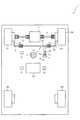
以下、本発明を実施するための形態について添付図面を参照して説明する。図1は、本発明の第1実施形態における車両1を模式的に示した模式図である。 DESCRIPTION OF EMBODIMENTS Hereinafter, embodiments for carrying out the present invention will be described with reference to the accompanying drawings. FIG. 1 is a schematic diagram schematically showing the vehicle 1 in the first embodiment of the present invention.
まず、図1を参照して、車両1の構成について説明する。車両1は、自車両の走行を自動で制御する自動走行をさせつつ、搭乗者の意思に沿って走行経路を決定できるように構成されている。ここで、自動走行とは、搭乗者がアクセルペダル、ブレーキペダルや車両1の操舵を操作しなくても、予め定めた走行軌道に沿って車両1を走行させることである。走行軌道とは、車両1が走行すべき軌道を示したものである。 First, the configuration of the vehicle 1 will be described with reference to FIG. The vehicle 1 is configured to be able to determine a travel route in accordance with a passenger's intention while performing automatic travel that automatically controls travel of the host vehicle. Here, the automatic travel refers to causing the vehicle 1 to travel along a predetermined travel path without the passenger operating the accelerator pedal, the brake pedal, or the steering of the vehicle 1. The traveling track indicates a track on which the vehicle 1 should travel.
この車両1では、搭乗者が指示した方向に車両を自動で走行させつつ、搭乗者の指示に基づいて走行経路が選択されたタイミングとその選択された走行経路とを搭乗者に確実に把握させるように構成されている。以下、詳細に説明する。 In the vehicle 1, while the vehicle is automatically traveling in the direction instructed by the passenger, the passenger is surely grasped when the travel route is selected based on the instruction from the passenger and the selected travel route. It is configured as follows. Details will be described below.
まず、車両1には、走行制御装置100が設けられている。走行制御装置100は、車両1の走行を制御するコンピュータ装置である。車両1の自動走行は、この走行制御装置100によって行われる。走行制御装置100の詳細構成については、図3を参照して後述する。 First, the vehicle 1 is provided with a
車両1は、走行制御装置100の他に、複数(本実施形態では4輪)の車輪2FL,2FR,2RL,2RRと、それら複数の車輪2FL〜2RRの内の一部(本実施形態では、左右の前輪2FL,2FR)を回転駆動する車輪駆動装置3と、複数の車輪2FL〜2RRの内の一部(本実施形態では、左右の前輪2FL,2FR)を操舵する操舵駆動装置5及びステアリング装置6と、ジョイスティック装置13と、車両操舵角センサ20と、車両速度センサ22と、運転支援スイッチ25と、現在位置検出装置27と、VICS(登録商標)受信装置28と、を主に有している。 In addition to the
車輪2FL,2FRは、車両1の前方側に配置される左右の前輪であり、車輪駆動装置3によって回転駆動される駆動輪として構成されている。一方、車輪2RL,2RRは、車両1の後方側に配置される左右の後輪であり、車両1の走行に伴って従動する従動輪として構成されている。 The wheels 2FL and 2FR are left and right front wheels disposed on the front side of the vehicle 1 and are configured as driving wheels that are rotationally driven by the
車輪駆動装置3は、左右の前輪2FL,2FRに回転駆動力を付与するものであり、デファレンシャルギヤ(図示せず)及び一対のドライブシャフト31を介して左右の前輪2FL,2FRに接続されている。車輪駆動装置3は、車両1に設けられたアクセルペダル(図示せず)の踏み込み量に応じて、ドライブシャフト31を介して左右の前輪2FL,2FRに回転駆動力を付与する。これにより、車両1は、アクセルペダルの踏み込み量に応じた速度で走行する。 The
なお、車輪駆動装置3は、走行制御装置100から、目標とすべき車両速度を通知する制御信号に基づき、その通知された車両速度となるように、ドライブシャフト31を介して左右の前輪2FL,2FRに回転駆動力を付与するように構成してもよい。この場合、車輪駆動装置3は、走行制御装置100の入出力ポート95(図2参照)に接続され、走行制御装置100に設けられたCPU91(図2参照)から制御信号を受信可能に構成すればよい。 Note that the
操舵駆動装置5は、左右の前輪2FL,2FRを操舵するための装置であり、ステアリング装置6に回転駆動力を付与する電動モータ5a(図3参照)を備えて構成されている。ステアリング装置6は、ステアリングシャフト61と、フックジョイント62と、ステアリングギヤ63と、タイロッド64と、ナックルアーム65とを主に備えて構成されている。なお、ステアリング装置6は、ステアリングギヤ63がピニオン(図示せず)とラック(図示せず)とを備えたラックアンドピニオン機構によって構成されている。 The
操舵駆動装置5は、走行制御装置100からの制御信号によって電動モータ5aを駆動すると、電動モータ5aの回転駆動力がステアリング装置6のステアリングシャフト61に付与される。その回転駆動力は、ステアリングシャフト61を介してフックジョイント62に伝達されると共にフックジョイント62によって角度を変えられ、ステアリングギヤ63のピニオンに回転運動として伝達される。 When the
そして、ピニオンに伝達された回転運動はラックの直線運動に変換され、ラックが直線運動することで、ラックの両端に接続されたタイロッド64が移動し、ナックルアーム65を介して前輪2FL,2FRRが操舵される。これにより、車両1は、走行制御装置100から指示された操舵角で、前輪2FL,2FRが操舵される。 Then, the rotational motion transmitted to the pinion is converted into the linear motion of the rack. When the rack moves linearly, the
ジョイスティック装置13は、車両1の搭乗者から車両1の進行すべき方向の指示を受け付けるものであり、搭乗者によって操作され且つ複数の方向に傾倒可能な操作レバー13aを有している。 The
ここで、図2を参照して、ジョイスティック装置13の詳細について説明する。図2(a)は、操作レバー13aが操作されていない状態のジョイスティック装置13を模式的に示した模式図であり、図2(b)は、操作レバー13aが所定の方向に傾倒された状態のジョイスティック装置13を模式的に示した模式図である。ここで、図2に示すx軸は、車両1の左右方向を示す軸であり、車両1の進行方向右側が正方向とされている。また、y軸は車両1の前後方向を示す軸であり、前方側が正方向とされている。また、z軸は、車両1の上下方向を示す軸であり、上方側が正方向とされている。 Here, with reference to FIG. 2, the detail of the
ジョイスティック装置13は、通常、図2(a)に示す通り、操作レバー13aがz軸方向に直立した状態(以下「直立状態」と称す)となっている。操作レバー13aがこのような直立状態となっている場合、ジョイスティック装置13は、操作者(この場合、搭乗者)による操作待ち状態となっている。ジョイスティック装置13が操作待ち状態にあるとき、搭乗者は、操作レバー13aを任意の方向に傾倒させることができる。 As shown in FIG. 2A, the
例えば、操作者が、図2(b)に示した方向に、操作レバー13aを傾倒されたとする。ジョイスティック装置13は、操作レバー13aの傾倒方向θを検出する方向検出センサ13b(図3参照)を有しており、搭乗者によって傾倒された操作レバー13aの傾倒方向θを方向検出センサ13bによって検出して、その検出された傾倒方向θを走行制御装置100へ出力している。 For example, it is assumed that the operator tilts the
走行制御装置100は、ジョイスティック装置13から傾倒方向θを取得すると、その傾倒方向θに基づいて搭乗者によって指示された車両1の進行すべき方向を判断する。これにより、搭乗者は、該操作レバー13aを車両1の進行すべき方向に向けて傾倒操作することにより、その操作レバー13aの傾倒方向によって車両1の進行すべき方向を指示することができる。 When the traveling
なお、方向検出センサ13bによって検出される傾倒方向θは、x軸(正側)と操作レバー13aとのなす角度によって表される。例えば、操作レバー13aがx軸に沿って正側に傾倒された場合、傾倒方向θは0°として出力され、操作レバー13aがy軸に沿って正側に傾倒された場合、傾倒方向θは90°として出力され、操作レバー13aがx軸に沿って負側に傾倒された場合、傾倒方向θは180°として出力され、操作レバー13aがy軸沿って負側に傾倒された場合、傾倒方向はθ270°として出力される。 The tilt direction θ detected by the
また、操作レバー13aが操作されていないとき、即ち、直立状態となっている場合は、方向検出センサ13bは値を非出力とする。走行制御装置100は、方向検出センサ13bから値が出力されているか否かによって、操作レバー13aが搭乗者によって傾倒操作されているか否かを判断する。 When the
ジョイスティック装置13は、また、x軸傾倒アクチュエータ13c及びy軸傾倒アクチュエータ13dを有している(図3参照)。x軸傾倒アクチュエータ13cは、操作レバー13aをx軸方向へ傾倒させるアクチュエータであり、y軸傾倒アクチュエータ13dは、操作レバー13aをy軸方向へ傾倒されせるアクチュエータである。 The
走行制御装置100は、ジョイスティック装置13に対して、操作レバー13aの傾倒を指示可能に構成されており、例えば、走行制御装置100からジョイスティック装置13に対して、操作レバー13aを傾倒方向θに傾倒させるよう指示があった場合、x軸傾倒アクチュエータ13cはcosθ、y軸傾倒アクチュエータ13dはsinθが駆動されて、図2(b)に示す通りに、操作レバー13aが傾倒方向θへ傾倒させられる。 The
また、操作レバー13aが傾倒方向θに傾倒されているときに別の傾倒方向θ’が走行制御装置100からジョイスティック装置13に対して指示されると、操作レバー13aが傾倒方向θから傾倒方向θ’へ旋回する。こうして、ジョイスティック装置13は、搭乗者からの操作に因らずに、走行制御装置100からの制御信号に基づいて操作レバー13aが傾倒可能で且つその傾倒方向が旋回させられる。 Further, if another traveling direction θ ′ is instructed from the traveling
図1に戻って、説明を続ける。車両操舵角センサ20は、車両1に付与された操舵角を検出して、検出した操舵角を走行制御装置100へ出力する装置であり、ステアリングシャフト61に取り付けられている。車両操舵角センサは、基準位置からのステアリングシャフト61の回転角度に基づいて、左右の前輪2FL,2FRの操舵角δを算出し、その算出結果を車両1の操舵角として走行制御装置100へ出力する。 Returning to FIG. 1, the description will be continued. The vehicle
走行制御装置100は、車両操舵角センサ20より取得した車両1の操舵角に基づいて、車両1の自動走行を制御する。また、走行制御装置100は、設定された走行軌道に沿って車両1を道なりに自動走行させている場合に、車両操舵角センサ20より取得した車両1の操舵角に基づいて、ジョイスティック装置13のx軸傾倒アクチュエータ13cおよびy軸傾倒アクチュエータ13dを駆動することにより、操作レバー13aの傾倒方向を移動させる。これにより、操作レバー13aによって、その傾倒方向により車両1が進む方向を搭乗者に容易に認識させることができる。よって、搭乗者に安心感を与えながら、車両1を自動で走行させることができる。 The
車両速度センサ22は、車両1の車両速度を検出して、検出した車両速度を走行制御装置100へ出力する装置である。車両速度センサ22は、前輪2FL,2FRのそれぞれに設けられ、各前輪2FL,2FR毎に車輪速度を検出する車輪速度検出センサ(図示せず)と、車輪速度検出センサにより検出された各前輪2FL,2FRの車輪速度を基に、車両1の車両速度を算出して、算出した車両速度を走行制御装置100へ出力する出力回路(図示せず)とを有している。 The
走行制御装置100は、車両速度センサ22より取得した車両1の車両速度に基づいて、車両1の自動走行を制御する。また、詳細については後述するが、走行制御装置100は、交差点や駐車場等へ出入りするための通路との接続点(以下、交差点および該接続点をまとめて「交差点等」とも称す)の手前で、搭乗者からジョイスティック装置13によって指示された車両1の進行すべき方向に従って新たに車両1が走行すべき走行軌道を設定し、その設定後に設定された走行軌道に沿って車両1を一の道路または駐車場等への通路(以下、道路および通路とをまとめて「道路等」とも称す)へと旋回させる場合に、車両速度センサ22より取得した車両速度と車両操舵角センサ20により取得した車両1の操舵角とに基づいて車両1のヨーレートを算出し、その算出したヨーレートと同じ角速度で車両1の旋回方向とは逆方向に、ジョイスティック装置13の操作レバー13aの傾倒方向を旋回動作させるようx軸傾倒アクチュエータ13cおよびy軸傾倒アクチュエータ13dを駆動する。 The
これにより、操作レバー13aは、車両1の外から見ると常に一定の方向を向いて傾倒することになる(図8参照)。ここで、走行制御装置100は、新たに車両1が走行すべき走行軌道を設定した場合に、その走行軌道によって車両1が進入することになる道路等の方向(それまで車両1が走行していた道路等に対して、新たに設定された走行軌道により車両1が進入することになる道路等が分岐している方向)へジョイスティック装置13の操作レバー13aを傾倒させている。 As a result, the
よって、その後、設定された走行軌道に沿って進行すべき道路等へと車両1を旋回させる場合に、操作レバー13aの傾倒方向を上記のように旋回動作させ、車両1の外から見たときに常に一定の方向を向くように操作レバー13aを傾倒させれば、車両1が旋回している間、操作レバー13aによって、車両1が進入することになる道路等の方向を常に示すことができる。従って、車両1が旋回している間、その車両1が進行する道路等の方向を搭乗者に常に示すことができるので、車両1が間違いなく進行したい道路等へ進行していっていることを搭乗者に認識させることができる。よって、車両1の搭乗者に安心感を与えることができる。 Therefore, when the vehicle 1 is subsequently turned to a road or the like that should travel along the set travel path, the tilting direction of the
運転支援スイッチ25は、自動走行により車両1を走行させたい場合に、搭乗者が押下するスイッチである。運転支援スイッチ25が搭乗者により押下され、オン状態にされると、走行制御装置100は、選択された走行軌道に沿って自動走行を行う自動走行制御を実行する。 The driving
また、運転支援スイッチ25がオン状態とされると、走行制御装置100は、後述するジョイスティック制御処理(図4参照)を実行する。このジョイスティック制御処理では、交差点や駐車場等へ出入りするための通路との接続点の手前で、搭乗者が傾倒したジョイスティック装置13の操作レバー13aの傾倒方向を方向検出センサ13bの検出結果から取得し、その傾倒方向から搭乗者が指示した車両1の進行すべき方向を判断して、走行軌道の候補である複数の推奨軌道の中から1つ走行軌道として選択する。 In addition, when the driving
走行制御装置100は、この選択された走行軌道に沿って車両1が走行するように車両1の走行を制御することで、搭乗者が進行したい道路や通路へ車両1を進行させることができる。 The
ジョイスティック制御処理では、また、走行軌道に沿って車両1の走行を制御している間、ジョイスティック装置13の操作レバー13aをx軸傾倒アクチュエータ13cおよびy軸傾倒アクチュエータ13dによって搭乗者の操作に因らずに傾倒させ、x軸傾倒アクチュエータ13cおよびy軸傾倒アクチュエータ13dにより、その傾倒方向を車両1のヨーレートや前輪2FL,2FRの操舵角に応じて旋回させる。これにより、ジョイスティック装置13の操作レバー13aによって、その傾倒方向により、自動走行している車両1が進行しようとしている道路等の方向を示したり、その車両1が進む方向を指し示したりすることができる。 In the joystick control process, the
また、運転支援スイッチ25が搭乗者により再び押下されオフ状態されると、車両1の自動走行が終了する。 When the driving
現在位置検出装置27は、車両1の現在位置(緯度、経度からなる絶対座標値)を検出するためのものである。この現在位置検出装置27は、人工衛星を利用して車両の位置を測定するGPS(Global Positioning System)受信装置、地磁気を検出して車両の方位を求める地磁気センサ、ジャイロセンサ、車速センサの1又は複数が使用される。更には、地図情報DB92bと走行軌道とのマップマッチング或いは地図情報DB92bとカメラ又はレーザレーダ等でとらえた構造物や標識等とのマッチングにより現在位置を同定してもよい。 The current
現在位置検出装置27で検出した車両1の現在位置は、走行制御装置100へ送信される。走行制御装置100は、現在位置検出装置27より受信した車両1の現在位置に基づいて、車両1が走行軌道に沿って走行するように、車両1の自動走行を制御する。また、走行制御装置100は、その車両1の現在位置に基づいて地図情報データDB92bから、現在車両1が進行している道路等に接続された他の道路等に関する道路データを取得して、推奨軌道を生成する。 The current position of the vehicle 1 detected by the current
VICS受信装置28は、渋滞や交通規制などの道路交通情報を提供するVICS(Vehicle Information and Communication System)より、その道路交通情報を受信する装置である。VICS受信装置28は、受信した道路交通情報を走行制御装置100へ送信する。走行制御装置100は、その道路交通情報に含まれる交通規制情報を基に、車両1が進行している道路等に接続された他の道路等が走行可能か否かを判断し、走行可能な道路等に対して、推奨軌道を生成する。 The
次いで、図3を参照して、走行制御装置100の詳細構成について説明する。図3は、走行制御装置100を含む車両1の電気的構成を示したブロック図である。 Next, a detailed configuration of the
走行制御装置100は、CPU91、フラッシュメモリ92及びRAM93を有しており、それらがバスライン94を介して入出力ポート95に接続されている。入出力ポート95には、上述した、操舵駆動装置5、ジョイスティック装置13、車両操舵角センサ20、車両速度センサ22、運転支援スイッチ25、現在位置検出装置27、VICS受信装置28、及び、その他の入出力装置99などが接続されている。 The
CPU91は、入出力ポート95に接続されたジョイスティック装置13の方向検出センサ13b、車両操舵角センサ20、車両速度センサ22、運転支援スイッチ25、現在位置検出装置27、VICS受信装置28等から送信された各種の情報に基づいて、操舵駆動装置5やジョイスティック装置13のx軸傾倒アクチュエータ13c及びy軸傾倒アクチュエータ13d等を制御する演算装置である。 The
フラッシュメモリ92は、CPU91によって実行される制御プログラムや固定値データ等を記憶するための書き換え可能な不揮発性のメモリである。このフラッシュメモリ92には、プログラムメモリ92a及び地図情報DB92bが設けられている。 The
プログラムメモリ92aは、CPU91にて実行される各種のプログラムが格納されたフラッシュメモリ92上の領域である。後述する図4のフローチャートに示すジョイスティック制御処理、図5のフローチャートに示す走行軌道選択処理、図7の処理に示すジョイスティック旋回処理、その他、設定された走行軌道に沿って車両1の走行を制御する処理等をCPU91にて実行させるための各プログラムは、このプログラムメモリ92aに格納されている。 The
CPU91は、このプログラムメモリ92aに格納された各プログラムに従って各種処理を実行することで、搭乗者が指示した方向に車両を自動で走行させつつ、搭乗者の指示に基づいて走行経路が選択されたタイミングとその選択された走行経路とを搭乗者に確実に把握させることができる。 The
地図情報DB92bは、地図および道路に関する情報が格納されたデータベースである。この地図情報DB92bでは、各種施設の場所や、各種道路の位置などが、緯度、経度からなる絶対座標値によって示されている。 The
走行制御装置100は、現在位置検出装置27によって検出された車両1の現在位置と、地図情報DB92bに格納された情報とから、車両1が進行している道路等に接続された他の道路等を判断する。走行制御装置100は、地図情報DB92bより判断した他の道路等に、VICS受信装置28にて受信した道路交通情報を加味して、走行可能な道路等を判断する。そして、その走行可能な道路等に対して、推奨軌道を生成する。 The
地図情報DB92bには、また、各道路に関する各種道路情報、例えば、その道路に対する進入禁止、車両通行止め等の各種規制情報や、その道路の幅、車線数、交差点間距離(道路の長さ)、及び、その道路における事故履歴、その他注意情報等が各道路に対して対応付けされている。 The
走行制御装置100は、地図情報DB92bにおいて各道路に対応付けられた規制情報に基づいて、その道路が走行可能な道路か否かを判断する。また、走行制御装置100は、地図情報DB92bにおいて各道路に対応付けられた道路の幅や車線数、事故履歴、その他注意情報等に基づいて、各道路等に対し危険ポテンシャルを算出する。そして、走行制御装置100は、算出した危険ポテンシャルが最も低い地点を車両1が走行するように、各道路等に対し、推奨軌道を生成する。 The
なお、車両1にナビゲーション装置が別途設けられている場合、走行制御装置100は、フラッシュメモリ92に地図情報DB92bを格納することに代えて、そのナビゲーション装置が有する地図情報DBを用いて上記の処理を行うようにしてもよい。この場合、ナビゲーション装置が走行制御装置100の入出力ポート95に接続され、走行制御装置100が入出力ポート95を介してナビゲーション装置より地図情報DBに格納された各種情報を取得するように構成すればよい。 When the navigation device is separately provided in the vehicle 1, the traveling
RAM93は、書き換え可能な揮発性のメモリであり、CPU91によって実行される制御プログラムの実行時に各種のデータを一時的に記憶するためのメモリである。RAM93には、推奨軌道メモリ93aと、走行軌道メモリ93bと、走行軌道走行中フラグ93cとが設けられている。 The
推奨軌道メモリ93aは、走行制御装置100が生成した推奨軌道情報(推奨軌道上に位置する各点の位置および各点において車両が向くべき方向を示す情報)を推奨軌道毎に格納するために、RAM93に設けた領域である。走行制御装置100は、車両1が進行している道路等(道路および駐車場等へ出入りするための通路)と、その道路等に接続された他の道路等とに対して、それらの道路等を走行すると仮定した場合に車両1が走行すべき軌道である推奨軌道を、各道路等に対して生成する。ここで各道路等に対して生成された1以上の推奨軌道情報が、推奨軌道毎に推奨軌道メモリ93aに格納される。 The recommended track memory 93a stores the recommended track information generated by the traveling control device 100 (information indicating the position of each point on the recommended track and the direction in which the vehicle should face) for each recommended track. This is an area provided in the
走行軌道メモリ93bは、これから車両1が走行すべき軌道を示した走行軌道情報(走行軌道上に位置する各点の位置および各点において車両が向くべき方向を示す情報)を格納するために、RAM93に設けた領域である。走行制御装置100は、走行軌道メモリ93bに格納された走行軌道情報を取得し、その軌道に沿って車両1が走行するように、車両1の走行を制御する。 The traveling
また、走行制御装置100は、ジョイスティック装置13の操作状態に基づいて、推奨軌道メモリ93aに格納された1以上の推奨軌道の中から走行軌道を選択し、その軌道情報を走行軌道情報として走行軌道メモリ93bに格納する。 The
具体的には、車両1が道路等の分岐点手前を走行している場合に、走行制御装置100は、ジョイスティック装置13に設けられた操作レバー13aの傾斜方向θと略等しい角度で、現在走行している道路等から分岐している道路等を抽出し、その道路等に対して生成された推奨軌道を走行軌道として選択して、その軌道情報を走行軌道メモリ93bに格納する。 Specifically, when the vehicle 1 is traveling in front of a branch point such as a road, the traveling
これにより、走行制御装置100は、新たに格納された走行軌道情報に従って、車両1の走行を制御することになる。ここで、新たに格納された走行軌道は、上述した通り、搭乗者が操作したジョイスティック装置13の傾斜歩行θに近い角度で、現在走行している道路等から分岐している道路等に対して生成された推奨軌道である。よって、新たに格納された走行軌道に沿って車両1を自動走行させることで、搭乗者が進行したい道路等へ車両1を進行させることができる。 Thereby, the traveling
また、搭乗者は、現在走行している道路等から別の道路等へ進行させたい場合、その現在走行している道路等と進行したい別の道路等とのなす角度を、ジョイスティック装置13の傾斜方向θとして、ジョイスティック装置13を操作すればよい。よって、車両1の現在位置から進行したい道路等の方向をジョイスティック装置13の傾斜方向として搭乗者に操作させる場合と比べ、搭乗者はその操作を直感的に行うことができる。よって、搭乗者に対して、ジョイスティック装置13の操作を容易に行わせることができる。 Further, when the passenger wants to travel from the currently traveling road to another road, the angle between the currently traveling road and the other road that he / she wants to travel is determined by the inclination of the
走行軌道走行中フラグ93cは、車両1が走行軌道メモリ93bに格納された走行軌道情報に基づいて車両1の自動走行を行っているか否かを示すフラグであり、オンの場合に、車両1が走行軌道メモリ93bに格納された走行軌道情報に基づいて車両1の自動走行を行っていることを示し、オフの場合に、車両1が走行軌道メモリ93bに格納された走行軌道情報に基づいて車両1の自動走行を行っていないことを示す。 The running
この走行軌道走行中フラグ93cは、車両1の電源投入時(車両1のイグニッションスイッチがオンされた時)に初期値としてオフが設定される。また、運転支援スイッチ25がオン状態からオフ状態とされ、ジョイスティック制御処理(図4参照)を終了させる場合に、CPU91は、走行軌道走行中フラグをオフに設定する(S11参照)。これにより、運転支援スイッチ25がオフ状態からオン状態とされてCPU91がジョイスティック制御処理の実行を開始するときは、走行軌道走行中フラグ93cはオフとなっている。 The running
CPU91は、ジョイスティック制御処理(図4)の実行を開始すると、走行軌道走行中フラグ93cがオフになっていることを確認した上で、道路等の分岐点の手前であるか否かにかかわらず、推奨軌道を1以上生成し、搭乗者により操作されたジョイスティック装置13の操作レバー13aの傾倒方向θに基づいて、生成した1以上の推奨軌道の中から走行軌道を1つ選択する(S5)。これにより、走行制御装置100は、運転支援スイッチ25がオフ状態からオン状態とされたときに道路等の分岐点の手前に車両1が位置していなくても、走行軌道を設定でき、この設定された走行軌道に沿って車両1の自動走行を開始できる。 When starting the execution of the joystick control process (FIG. 4), the
また、CPU91は、ジョイスティック制御処理(図4)において、一旦走行軌道を設定すると、走行軌道走行中フラグ93cをオンに設定する(S6)。これにより、一旦走行軌道が設定されると、後は、その走行軌道の設定が、道路等の分岐点の手前のみ行われるようになっている。これにより、車両1の自動走行が行われている最中は、道路等の分岐点の手前以外の領域で、不用意に走行軌道が決定されることを防止できるので、車両1を安全に自動走行させることができる。 Further, in the joystick control process (FIG. 4), the
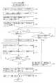
次いで、図4〜図9を参照して、車両1に搭載された走行制御装置100のCPU91により実行されるジョイスティック制御処理について説明する。図4は、そのジョイスティック制御処理を示すフローチャートである。 Next, a joystick control process executed by the
ジョイスティック制御処理は、搭乗者が傾倒したジョイスティック装置13の操作レバー13aの傾倒方向から搭乗者が指示した車両1の進行すべき方向を判断して、走行軌道の候補である複数の推奨軌道の中から1つ走行軌道として選択する処理である。また、ジョイスティック制御処理は、走行軌道に沿って車両1の走行を制御している間、ジョイスティック装置13の操作レバー13aを搭乗者の操作に因らずに傾倒させ、その傾倒方向を車両1のヨーレートや前輪2FL,2FRの操舵角に応じて旋回させる処理も行う。 The joystick control process determines the direction in which the vehicle 1 should travel from the tilt direction of the
このジョイスティック制御処理は、運転支援スイッチ25が搭乗者によって押下され、オン状態にされると、CPU91によって処理が開始される。ジョイスティック制御処理では、まず、現在位置検出装置27によって検出された車両1の現在位置を取得する(S1)。 This joystick control process is started by the
次いで、走行軌道走行中フラグ93cがオンか否かを判断し(S2)、走行軌道走行中フラグ93cがオフの場合は(S2:No)、そのままS4の処理へ移行する。また、走行軌道走行中フラグ93cがオンの場合は(S2:Yes)、続いて、車両1が道路等の分岐点の手前に位置しているか否かを判断する(S3)。なお、分岐点は、交差点だけでなく、駐車場等へ出入りするための通路への接続点も含まれる。 Next, it is determined whether or not the running
この分岐点か否かの判断は、S1の処理にて取得された車両1の現在位置と、地図情報DB92bに格納された地図や道路に関する情報とを比較することにより行われる。即ち、S3の処理では、車両1の現在位置から、車両1の前方の所定の距離(例えば、30m)範囲内に、交差点や、駐車場等へ出入りする通路への接続点が存在するか否かを、地図情報DBに格納された情報から判断する。そして、車両1の前方の所定の距離範囲内に、交差点や駐車場等へ出入りする通路への接続点が存在する場合に、車両1が道路等の分岐点の手前に位置していると判断する。 The determination as to whether or not the vehicle is a branch point is made by comparing the current position of the vehicle 1 acquired in the process of S1 with information about a map or road stored in the
S3の処理の結果、車両1が道路等の分岐点の手前に位置していると判断される場合は(S3:Yes)、S4の処理へ移行し、車両1が道路等の分岐点の手前の位置していないと判断される場合は(S3:No)、S12の処理へ移行する。 As a result of the process of S3, when it is determined that the vehicle 1 is located in front of a branch point such as a road (S3: Yes), the process proceeds to S4 and the vehicle 1 is in front of a branch point such as a road. If it is determined that the position is not located (S3: No), the process proceeds to S12.
ここで、走行軌道走行中フラグ93cは、ジョイスティック制御処理の実行がCPU91によって開始された時点でオフに設定されている。即ち、ジョイスティック制御処理を開始直後は、車両1が道路等の分岐点の手前に位置しているか否かにかかわらず、S2:Noの分岐を通って、S4の処理へ移行する。 Here, the running
S4以降の処理では、1以上の推奨軌道を生成して、搭乗者により操作されたジョイスティック装置13の操作レバー13aの傾倒方向に基づいて、推奨軌道の中から1つ走行軌道を選択し設定する。よって、ジョイスティック制御処理の開始直後は、車両1が道路等の分岐点の手前に位置しているか否かにかかわらず、走行軌道を設定する。これにより、走行制御装置100は、運転支援スイッチ25がオフ状態からオン状態とされたときに道路等の分岐点の手前に車両1が位置していなくても、走行軌道を設定でき、この設定された走行軌道に沿って車両1の自動走行を開始できる。 In the processing after S4, one or more recommended trajectories are generated, and one travel trajectory is selected and set from the recommended trajectories based on the tilt direction of the
また、一旦走行軌道が設定されると、後述するように、走行軌道走行中フラグ93cがオンに設定される。よって、その後は、S2:Yesの分岐を通って、S3の判断が行われる。これにより、S3の判断によって、車両1が道路等の分岐点の手前に位置している場合に限り、S4以降の処理が実行されて走行軌道の設定が行われる。これにより、車両1の自動走行が行われている最中は、道路等の分岐点の手前以外の領域で不用意に走行軌道が決定されることを防止できるので、車両1を安全に自動走行させることができる。 Also, once the traveling track is set, the traveling
S4の処理では、ジョイスティック装置13に対して、操作レバー13aを直立状態とするように指示する(S4)。これにより、ジョイスティック装置13は、x軸傾倒アクチュエータ13cおよびy軸傾倒アクチュエータ13dを制御して、操作レバー13aを直立状態とする。 In the process of S4, the
ここで、後述するS5の処理では、搭乗者からジョイスティック装置13の操作レバー13aの操作を受け付け、搭乗者が操作した操作レバー13aの傾倒方向を取得して、搭乗者が希望する車両1の進行すべき方向を判断する。S4の処理では、このS5の処理の前に、ジョイスティック装置13の操作レバー13aを直立状態とすることによって、車両1が進行すべき方向の指示を行うように、搭乗者に操作レバー13aの操作を促すことができる。 Here, in the process of S5 described later, the operation of the
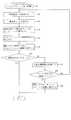
S4の処理の後、次いで、走行軌道選択処理を実行する(S5)。ここで、図5を参照して、走行軌道選択処理の詳細について説明する。図5は、CPU91により実行される走行軌道選択処理を示すフローチャートである。 After the process of S4, next, a traveling track selection process is executed (S5). Here, with reference to FIG. 5, the details of the traveling track selection processing will be described. FIG. 5 is a flowchart showing a traveling track selection process executed by the
この走行軌道選択処理は、搭乗者が傾倒したジョイスティック装置13の操作レバー13aの傾倒方向から搭乗者が指示した車両1の進行すべき方向を判断して、走行軌道の候補である複数の推奨軌道の中から1つ走行軌道として選択する処理である。 In this travel trajectory selection process, the recommended direction of travel of the vehicle 1 indicated by the occupant is determined from the tilt direction of the
走行軌道選択処理では、まず、車両1の進行方向で最も近い分岐点(交差点や駐車場等へ出入りする通路への接続点)を地図情報DB92bより探索し、その分岐点に関するデータ(分岐点の位置情報)を地図情報DB92bより取得する(S21)。 In the travel trajectory selection process, first, the
次いで、分岐点に接続している道路等に関するデータ(道路等の位置情報)も、地図情報DB92bより取得し(S22)、現在進行中の道路等に関するデータも含めてRAM93に一時的に保存する。 Next, data relating to roads and the like connected to the branch point (location information such as roads) is also acquired from the
続いて、S22の処理でデータを取得した道路等の各々に対して進入可能か否かを、地図情報DB92bの道路情報に含まれる進入禁止や車両通行止め等の規制情報、事故履歴、その他注意情報と、VICS受信装置28にて受信した道路交通情報に含まれている交通規制情報と、を基に判断し、通れない道路等については、その道路データをRAM93から削除する(S23)
そして、RAM93にデータが格納された各道路等について、それぞれ、その道路等へ車両1を進行させるために必要な車両1の軌道を求め、その軌道を各道路等の推奨軌道として、その推奨軌道情報を推奨軌道メモリ93aに格納する(S24)。Subsequently, whether or not it is possible to enter each of the roads and the like for which data has been acquired in the process of S22, regulation information such as entry prohibition and vehicle closure included in the road information of the
Then, for each road, etc., in which data is stored in the
ここで、一の道路等へ車両1を進行させるために必要な車両1の軌道の求め方としては、例えば、車両1に設けたカメラ、レーザ、ソナー等の各種センサから車両1の周辺情報を取得し、その取得した周辺情報やVICS受信装置29にて受信した道路交通情報、地図情報DB92bに含まれる各種地図、道路情報から、道路等の幅、障害物の有無等を判断して道路上の各地点における危険ポテンシャルを生成し、その危険ポテンシャルの最も低い地点を通過するように、車両1の軌道を求めてもよい。 Here, as a method of obtaining the trajectory of the vehicle 1 necessary for the vehicle 1 to travel on one road or the like, for example, the surrounding information of the vehicle 1 is obtained from various sensors such as a camera, a laser, and a sonar provided in the vehicle 1. On the road by determining the width of the road, the presence or absence of obstacles, etc. from the acquired peripheral information, road traffic information received by the VICS receiver 29, various maps included in the
また、軌道の生成対象となる道路等へスムーズに進入または進行できる軌道を算出してもよい。この場合、クロソイド曲線を考慮して、スムーズに進行または進入できる軌道を算出してもよいし、曲率半径が大きくなるようにスムーズに進行または進入できる軌道を算出しても良い。 Alternatively, a trajectory that can smoothly enter or proceed on a road or the like on which a trajectory is to be generated may be calculated. In this case, in consideration of the clothoid curve, a trajectory that can proceed or enter smoothly can be calculated, or a trajectory that can proceed or enter smoothly so that the radius of curvature can be increased.
また、軌道の生成対象となる道路等へ最短距離で進行または進入できる軌道を算出してもよい。更に、地図情報DB92bの道路情報に、各道路に対して軌道を含めておき、その道路情報に基づいて軌道を生成してもよい。 Alternatively, a trajectory that can travel or enter the road or the like that is the target of trajectory generation at the shortest distance may be calculated. Furthermore, the road information of the
S24の処理の後、次いで、ジョイスティック装置13の操作レバー13aが搭乗者により操作されたかを判定する(S25)。この判定では、ジョイスティック装置13の方向検出センサ13bから出力される操作レバー13aの傾倒方向を示す値が出力されているか否かを判断することによって行われる。即ち、方向検出センサ13bから値が出力されている場合は、操作レバー13aが搭乗者により操作された、と判断し、方向検出センサ13bから値が非出力となっている場合は、操作レバー13aが搭乗者により操作されていない、と判断する。 After the process of S24, it is then determined whether the
そして、このS25の処理により、ジョイスティック装置13の操作レバー13aが搭乗者により操作されたと判定された場合は(S25:Yes)、ジョイスティック装置13の操作レバー13aの傾倒方向θを方向検出センサ13bより取得する(S26)。 When it is determined by the processing of S25 that the
次に、S22,S23の処理によりRAM93に格納された道路データ、即ち、分岐点に接続されている道路データを1つRAM93より取得し(S27)、その道路データを取得した道路等と車両1が現在走行している道路等とのなす角度φをその道路データから求めて、求めた角度φとS26の処理にて取得したジョイスティック装置13の操作レバー13aの傾倒方向θとを比較する(S28)。 Next, the road data stored in the
そして、分岐点に接続された道路等、即ち、S22,S23の処理によりRAM93に格納された道路データがある道路等の全てに対して、S28の処理によるチェック(道路等のなす角度θとジョイスティック装置13の傾倒方向δとの比較)を行ったか否かを判断する(S29)。その結果、全ての道路等に対してS28の処理によるチェックを行っていない場合は(S29:No)、S27の処理へ戻る。また、S29の処理の結果、全ての道路等に対してS28の処理によるチェックを行っていた場合は(S29:Yes)、S30の処理へ移行する。 Then, all the roads connected to the branch points, that is, the roads having road data stored in the
これにより、分岐点に接続された全ての道路等に対して、その道路等と車両1が現在走行している道路等とのなす角度φが求められ、その角度φとジョイスティック装置13の傾倒方向θとが比較される。 Thus, for all roads connected to the branch point, an angle φ formed by the road and the road where the vehicle 1 is currently traveling is obtained, and the angle φ and the tilt direction of the
ここで、図6を参照して、S28の処理で求められる一の道路等と車両1が現在走行している道路等とのなす角度φについて説明する。図6(a)は、交差点(分岐点)70に接続された道路のうち、車両1の前方方向にある道路72と車両1が現在走行している道路71とのなす角度φaを示す図であり、図6(b)は、交差点(分岐点)70に接続された道路のうち、車両1の左前方左折方向にある道路73と車両1が現在走行している道路71とのなす角度φbを示す図であり、図6(c)は、交差点(分岐点)70に接続された道路のうち、車両1の左後方左折方向にある道路74と車両1が現在走行している道路71とのなす角度φcを示す図である。 Here, with reference to FIG. 6, the angle φ formed by one road or the like obtained in the process of S28 and the road or the like on which the vehicle 1 is currently traveling will be described. FIG. 6A is a diagram illustrating an angle φa formed by a
各道路等と車両1が現在走行している道路等とのなす角度φは、それぞれ、次のように算出される。即ち、算出対象の道路等において交差点70との接続点An(図6(a)ではn=1、図6(b)ではn=2、図6(c)ではn=3)から、道なりに距離d離れた点Bnへのベクトルの方向を求める。そして、車両1が現在走行している道路71と交差点70との接続点Ayから、道なりに距離l離れた点Bへのベクトルを180°回転された方向をy軸とし、各道路等が存在する平面上でy軸と直行する軸をx軸とした場合の、そのx軸(正側)と点Anから点Bnへのベクトルとのなす角度を、角度φnとして算出する。 The angle φ formed between each road and the road on which the vehicle 1 is currently traveling is calculated as follows. That is, the road from the connecting point An (n = 1 in FIG. 6A, n = 2 in FIG. 6B, n = 3 in FIG. 6C) with the
ここで、方向検出センサ13bによって検出される操作レバー13aの傾倒方向θは、図6(a)〜(c)に示す通り、車両1の左右方向に設定されたx軸(正側)と操作レバー13aとのなす角度によって表されている。よって、図6(a)〜(c)に示した方法で算出した、各道路等と車両1が現在走行している道路等とのなす角度φと、S26の処理にて取得したジョイスティック装置13の操作レバー13aの傾倒方向θとを単純に比較することで、傾倒方向θに最も近い角度φが算出された道路等が、搭乗者によって指示された進行すべき車両1の方向にある道路等とすることができる。 Here, the tilt direction θ of the
図5に戻り、説明を続ける。S30の処理では、S28の処理の結果、分岐点(交差点70)に接続された道路等(道路72〜74)のうち、その道路等と車両1が現在走行している道路等(道路71)とのなす角度φが、ジョイスティック装置13の操作レバー13aの傾倒方向θに最も近い道路等を抽出し、その道路等における角度φが、ジョイスティック装置13の傾倒方向θに略等しいものとして、その道路等に対して生成された推奨軌道を走行軌道として選択する(S30)。 Returning to FIG. 5, the description will be continued. In the process of S30, as a result of the process of S28, among the roads and the like (
そして、S30の処理により選択された推奨軌道情報を推奨軌道メモリ93aより読み出して、その軌道情報を走行軌道情報として走行軌道メモリ93bに格納し(S31)、走行軌道選択処理を終了する。 Then, the recommended trajectory information selected by the process of S30 is read from the recommended trajectory memory 93a, the trajectory information is stored as travel trajectory information in the
これにより、走行制御装置100は、S30の処理によって新たに格納された走行軌道情報に従って、車両1の走行を制御する。S28及びS30の処理から分かる通り、S31の処理によって新たに格納された走行軌道は、搭乗者が操作したジョイスティック装置13の傾倒方向θに近い角度で、現在走行している道路等から分岐している道路等に対して生成された推奨軌道である。よって、車両1を自動走行させつつ、搭乗者の意思に沿って走行軌道を決定できる。 Thereby, the traveling
一方、S25の処理の結果、ジョイスティック装置13の操作レバー13aが搭乗者により操作されていないと判定された場合は(S25:No)、S4の処理にて操作レバー13aを直立状態としてからの時間が、操作受付時間(例えば、5秒)を経過したか否かを判断する(S32)。 On the other hand, if it is determined that the
その結果、操作受付時間を経過していなければ(S32:No)、再びS25の処理へ移行する。これにより、操作受付時間の間にジョイスティック装置13の操作レバー13aが操作された場合には、S26移行の処理が実行され、搭乗者により操作された操作レバー13aの傾倒方向に基づいて、走行軌道が選択され、設定される。 As a result, if the operation reception time has not elapsed (S32: No), the process proceeds to S25 again. Thus, when the
一方、S32の処理により、S4の処理にて操作レバー13aを直立状態としてからの時間が、操作受付時間(例えば、5秒)を経過したと判断された場合は(S32:Yes)、S24の処理にて推奨軌道メモリ92aに格納された1以上の推奨軌道のうち、最も優先度の高い推奨軌道を走行軌道として選択する(S33)。ここで、優先度の高い推奨軌道とは、車両1が現在位置している道路等をそのまま道なりに進行させるための軌道である。 On the other hand, if it is determined by the process of S32 that the operation reception time (for example, 5 seconds) has elapsed after the
そして、S31の処理へ移行し、S3の処理により選択された推奨軌道情報を推奨軌道メモリ93aより読み出して、その軌道情報を走行軌道情報として走行軌道メモリ93bに格納し(S31)、走行軌道選択処理を終了する。 Then, the process proceeds to the process of S31, the recommended track information selected by the process of S3 is read from the recommended track memory 93a, and the track information is stored in the
ここで、ジョイスティック装置13の操作レバー13aの搭乗者による操作がないと判断される場合、搭乗者は、車両1の進行方向を維持したい、との意思を有していると判断できる。走行軌道選択処理では、この場合、車両1が現在位置している道路等をそのまま道なりに進行させるための推奨軌道を走行軌道として選択し、設定するので、車両1は現在走行中の道路等を道なりにそのまま走行するよう制御される。よって、搭乗者の意思を反映した自動走行を行うことができる。 Here, when it is determined that there is no operation by the rider on the
なお、S32の処理の結果、ジョイスティック装置13の操作レバー13aが操作受付時間を経過しても操作されていないと判断される場合は(S32:Yes)、S47の処理に代えて、車両1を停止させるようにしてもよい。そして、車両1の停止中にジョイスティック装置13の操作を検出すると、S26の処理へ移行してもよい。これにより、搭乗者に対してジョイスティック装置13の操作を促し、必ず搭乗者によるジョイスティック装置13の操作に従って走行軌道を決定することができる。 If it is determined that the
図4に戻り、ジョイスティック制御処理の説明を続ける。S5の走行軌道選択処理を完了すると、次に、走行軌道走行中フラグ93cをオンに設定する(S6)。これにより、一旦走行軌道が設定されると、S2の処理によって、後は、その走行軌道の設定が、道路等の分岐点の手前のみ行われるようになっている。これにより、車両1の自動走行が行われている最中は、道路等の分岐点の手前以外の領域で、不用意に走行軌道が決定されることを防止できるので、車両1を安全に自動走行させることができる。 Returning to FIG. 4, the description of the joystick control process will be continued. When the traveling track selection process in S5 is completed, the traveling
次いで、ジョイスティック装置13の操作レバー13aを傾倒させ、その操作レバー13aの傾倒方向を、選択した走行軌道によって車両1が進行していく道路等と現在車両1が進行中の道路等とのなす角度φ(図6参照)にするように、ジョイスティック装置13へ指示する(S7)。 Next, the
ジョイスティック装置13は、この指示により、x軸傾倒アクチュエータ13cおよびy軸傾倒アクチュエータ13dを駆動して、操作レバー13aを搭乗者の操作に因らずに傾倒させ、また、操作レバー13aの傾倒方向を、搭乗者の操作に因らずに、選択した走行軌道によって車両1が進行していく道路等と現在車両1が進行中の道路等とのなす角度φにする(図6参照)。 In response to this instruction, the
このように、走行軌道が設定されると、S7の処理によって、搭乗者の操作に因らずに、ジョイスティック装置13の操作レバー13aが傾倒される。これにより、車両1の進行すべき方向をジョイスティック装置13の操作レバー13aを操作することによって指示した搭乗者は、その指示によって走行軌道が選択され、設定されたことを確実に知ることができる。 As described above, when the traveling track is set, the
また、この場合、搭乗者が操作した操作レバー13aそのものが、選択した走行軌道によって車両1が進行していく道路等と現在車両1が進行中の道路等とのなす角度φの方向へ傾倒させられるので、搭乗者が自ら操作レバー13aを傾倒させた方向との対比から、直感的に且つ確実に、選択された走行軌道によって車両1が進む方向(道路等)を搭乗者に把握させることができる。よって、搭乗者が指示した方向に車両を自動で走行させつつ、搭乗者の指示に基づいて走行軌道が選択されたタイミングとその選択された走行軌道とを搭乗者に確実に把握させることができる。 In this case, the
S7の処理の後、S5の走行軌道選択処理によって設定された走行軌道から車両1が右左折等の旋回動作をするか否かを判断し(S8)、車両1が旋回動作する場合は(S8:Yes)、ジョイスティック旋回処理を実行して(S9)、S10の処理へ移行し、車両1が旋回動作しない場合は(S8:No)、S9の処理をスキップして、S10の処理へ移行する。 After the processing of S7, it is determined whether or not the vehicle 1 performs a turning operation such as a right or left turn from the traveling track set by the traveling track selection processing of S5 (S8). : Yes), the joystick turning process is executed (S9), and the process proceeds to S10. If the vehicle 1 does not turn (S8: No), the process of S9 is skipped and the process proceeds to S10. .
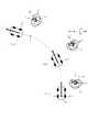
ここで、図7,図8を参照して、ジョイスティック旋回処理(S9)の詳細について説明する。図7は、CPU91によって実行されるジョイスティック旋回処理を示すフローチャートである。図8は、車両1が旋回している場合における、ジョイスティック装置13の操作レバー13aの傾倒方向の変化を模式的に示した模式図である。このジョイスティック旋回処理は、走行軌道に沿って車両1を旋回させながら、車両1の走行を制御している間、ジョイスティック装置13の操作レバー13aの傾倒を維持しつつ、搭乗者の操作に因らずにその傾倒方向を車両1のヨーレートに応じて旋回させる処理である。 Here, with reference to FIG. 7, FIG. 8, the detail of a joystick turning process (S9) is demonstrated. FIG. 7 is a flowchart showing a joystick turning process executed by the
ジョイスティック旋回処理が実行されると、まず、車両速度vを車両速度センサ22より取得し(S41)、次いで、前輪2FL,2FRに対して付与された操舵角δtを車両操舵角センサ20より取得する(S42)。そして、S41の処理により取得した車両速度vと、S42の処理により取得した操舵角δtとから、車両1のヨーレートωを算出する(S43)。 When the joystick turning process is executed, first, the vehicle speed v is acquired from the vehicle speed sensor 22 (S41), and then the steering angle δt given to the front wheels 2FL, 2FR is acquired from the vehicle
ここで、図9を参照しながら、車両1のヨーレートωの算出方法について説明する。図9は、車両1のヨーレートωの算出方法を説明するための図である。ヨーレートωを算出する場合、まず、図9に示す関係から、前輪2FL,2FRに付与された操舵角δtより、車両1の旋回半径Rを次式(1)によって求めることができる。 Here, a method for calculating the yaw rate ω of the vehicle 1 will be described with reference to FIG. 9. FIG. 9 is a diagram for explaining a method of calculating the yaw rate ω of the vehicle 1. When calculating the yaw rate ω, first, from the relationship shown in FIG. 9, the turning radius R of the vehicle 1 can be obtained from the steering angle δt given to the front wheels 2FL and 2FR by the following equation (1).
R = L/tan(δt) ・・・(1)
ここで、Lは、前輪2FL,2FRを結ぶ前輪軸と、後輪2RL,2RRを結ぶ後輪軸との距離であるホイールベースである。R = L / tan (δt) (1)
Here, L is a wheel base that is a distance between a front wheel shaft connecting the front wheels 2FL and 2FR and a rear wheel shaft connecting the rear wheels 2RL and 2RR.
そして、式(1)によって算出した旋回半径Rと、車両速度vとから、ヨーレートωを次式(2)によって算出できる。 Then, the yaw rate ω can be calculated by the following equation (2) from the turning radius R calculated by the equation (1) and the vehicle speed v.
ω = v/R ・・・(2)
S43の処理では、この(1),(2)式を用いて、S41の処理により取得した車両速度vと、S42の処理により取得した操舵角δtとから車両1のヨーレートωを算出する。ω = v / R (2)
In the process of S43, the yaw rate ω of the vehicle 1 is calculated from the vehicle speed v acquired by the process of S41 and the steering angle δt acquired by the process of S42, using the equations (1) and (2).
図7に戻り、ジョイスティック旋回処理の説明を続ける。S43の処理の後、次に、ジョイスティック装置13の操作レバー13aの傾倒方向を、S43の処理にて算出したヨーレートωと同じ角速度で、車両1の旋回方向とは逆方向に旋回させるべく、その操作レバー13aが傾倒すべき方向θを次式によって算出する(S44)。 Returning to FIG. 7, the description of the joystick turning process will be continued. After the process of S43, next, in order to turn the tilt direction of the

つまり、S44の処理では、車両1が交差点等の分岐点へ進入する時(t0)の操作レバー13aの傾倒方向θ0から、車両1のヨーレートωの積分値を引いた値を、操作レバー13aが傾倒すべき方向θとして算出する。That is, in the process of S44, the value obtained by subtracting the integral value of the yaw rate ω of the vehicle 1 from the tilting direction θ0 of the
そして、S44の処理により算出された傾倒方向θに操作レバー13aを旋回するように、ジョイスティック装置13へ指示する(S45)。これにより、ジョイスティック装置13は、x軸傾倒アクチュエータ13cおよびy軸傾倒アクチュエータ13dを駆動して、図8(b)に示すように、S45の処理により指示された傾倒方向θへ操作レバー13aを旋回させる。 Then, the
ここで、上述した通り、S45の処理によって指示される傾倒方向θは、両1が交差点へ進入する時(t0)の操作レバー13aの傾倒方向θ0から、車両1のヨーレートωの積分値を引いた値である。よって、S45の処理によって指示された傾倒方向θに、操作レバー13aを旋回させることによって、算出したヨーレートωと同じ角速度で、車両1の旋回方向とは逆方向に操作レバー13aを旋回させることができる。これにより、操作レバー13aは、図8に示す通り、車両1の外から見ると常に一定の方向を向いて傾倒することになる。Here, as described above, the tilt direction θ indicated by the process of S45 is the integral value of the yaw rate ω of the vehicle 1 from the tilt direction θ0 of the
また、走行制御装置100は、図4のS7の処理によって、新たに車両1が走行すべき走行軌道を設定した場合に、その走行軌道によって車両1が進入することになる道路等の方向(それまで車両1が走行していた道路等に対して、新たに設定された走行軌道により車両1が進入することになる道路等が分岐している方向)へジョイスティック装置13の操作レバー13aを傾倒させている。 In addition, when the
よって、その後、設定された走行軌道に沿って進行すべき道路等へと車両1を旋回させた場合に、このジョイスティック旋回処理によって、操作レバー13aの傾倒方向を上記のように旋回動作させ、車両1の外から見たときに常に一定の方向を向くように操作レバー13aを傾倒させることができるので、車両1が旋回している間、操作レバー13aによって、車両1が進入することになる道路等の方向を常に示すことができる。従って、車両1が旋回している間、その車両1が進行する道路等の方向を搭乗者に常に示すことができるので、車両1が間違いなく進行したい道路等へ進行していっていることを搭乗者に認識させることができる。よって、車両1の搭乗者に安心感を与えることができる。 Therefore, after that, when the vehicle 1 is turned to a road or the like to travel along the set traveling track, the tilting direction of the
S45の処理の後、S44の処理により算出された、ジョイスティック装置13の操作レバー13aの傾倒方向θが、車両1の前方方向を示す方向、即ち、90°の方向となったか否かを判断する(S46)。そして、操作レバー13aの傾倒方向θが90°の方向となっている場合は(S46:Yes)、走行軌道選択処理(S5)によって選択された走行軌道に沿って車両1を走行させた結果、搭乗者が進行したいと考えた道路等への旋回が完了し、その道路等へ完全に進入したことを意味する。 After the process of S45, it is determined whether or not the tilt direction θ of the
よって、この場合は、ジョイスティック旋回処理を終了し、車両1の旋回に合わせて操作レバー13aの傾倒方向を旋回させる処理を終了する。これにより、操作レバー13aの傾倒方向が旋回させられた後、その傾倒方向θが90°となった場合に、搭乗者に対して、搭乗者が進行したいと考えた道路等へ完全に進入したことを容易に把握させることができる。よって、搭乗者は、車両1における自動走行の状態を、操作レバー13aを介して知ることができるので、安心して車両1に自動走行を行わせることができる。 Therefore, in this case, the joystick turning process is ended, and the process of turning the tilting direction of the
一方、S46の処理により、S44の処理により算出された、ジョイスティック装置13の操作レバー13aの傾倒方向θが90°の方向となっていない場合は(S46:No)、続いて、車両1の現在位置を現在位置検出装置27より取得し(S47)、その車両1の現在位置から、車両1が、走行軌道選択処理(S5)によって選択された走行軌道に従って車両1を旋回させた時のカーブの終点Pを通過したか否かを判断する(S48)。 On the other hand, when the tilting direction θ of the
その結果、車両1がカーブの終点Pを未だ通過してなければ(S48:No)、S41の処理へ戻り、再び、S41〜S48の処理を実行する。これにより、S46の処理によって、操作レバー13aの傾倒方向が90°となった場合を除き、車両1の旋回が終了する地点Pを通過するまで、操作レバー13aは、車両1の旋回に合わせて傾倒方向が旋回させられる。 As a result, if the vehicle 1 has not yet passed the end point P of the curve (S48: No), the process returns to the process of S41, and the processes of S41 to S48 are executed again. As a result, the
一方、S48の処理により、車両1がカーブの終点Pを通過したと判断された場合は(S48:Yes)、傾倒方向として90°をジョイスティック装置13へ指示して(S49)、ジョイスティック旋回処理を終了する。これにより、走行軌道に従って車両1を旋回させた時のカーブの終点Pを車両1が通過すると、ジョイスティック装置13の操作レバー13aは、90°の方向、即ち、車両1の前方方向を示す方向に、傾倒される。 On the other hand, if it is determined in S48 that the vehicle 1 has passed the end point P of the curve (S48: Yes), 90 ° is instructed to the
ここで、走行軌道に従って車両1を旋回させた時のカーブの終点Pを車両1が通過した場合も、搭乗者が進行したいと考えた道路等への旋回が完了し、その道路等へ完全に進入したことを意味する。よって、車両1がカーブの終点Pを通過した後、操作レバー13aの傾倒方向θを90°とすることにより、搭乗者に対して、搭乗者が進行したいと考えた道路等へ完全に進入したことを容易に把握させることができる。よって、搭乗者は、車両1における自動走行の状態を、操作レバー13aを介して知ることができるので、安心して車両1に自動走行を行わせることができる。 Here, even when the vehicle 1 passes the end point P of the curve when the vehicle 1 is turned according to the traveling track, the turn to the road or the like that the passenger wants to travel is completed, and the road or the like is completely reached. It means that it entered. Therefore, after the vehicle 1 passes the end point P of the curve, the tilting direction θ of the
図4に戻り、ジョイスティック制御処理の説明を続ける。S3の処理の結果、車両1が道路等の分岐点の手前以外に位置していると判断される場合は(S3:No)、車両1は、分岐点の手前に位置していた場合に走行軌道選択処理(S5)によって設定された走行軌道に沿って道なりに自動走行する。 Returning to FIG. 4, the description of the joystick control process will be continued. As a result of the process of S3, when it is determined that the vehicle 1 is located in front of the branch point such as a road (S3: No), the vehicle 1 travels when it is located in front of the branch point. The vehicle automatically travels along the traveling track set by the track selection process (S5).
この場合、ジョイスティック制御処理では、まず、前輪2FFL,2FRに付与された操舵角δを車両操舵角センサ20より取得し(S12)、次いで、ジョイスティック装置13へ指示する傾倒方向、即ち、操作レバー13aを傾倒させるべき方向θを、S12の処理によって算出した操舵角δに基づいて、次式(3)により算出する(S13)。 In this case, in the joystick control process, first, the steering angle δ imparted to the front wheels 2FFL, 2FR is acquired from the vehicle steering angle sensor 20 (S12), and then the tilt direction instructing the
θ = δ×α+π/2 ・・・(3)
ここで、αは、前輪2FL,2FRの操舵角に対して、操作レバー13aの傾倒方向θを変化させる度合いを表す係数である。θ = δ × α + π / 2 (3)
Here, α is a coefficient representing the degree to which the tilt direction θ of the
そして、S13の処理により算出された傾倒方向θに操作レバー13aを旋回させるように、ジョイスティック装置13に指示する(S14)。そして、S10の処理へ移行する。 Then, the
S12〜S14の処理により、ジョイスティック装置13は、x軸傾倒アクチュエータ13cおよびy軸傾倒アクチュエータ13dを駆動して、操作レバー13aの傾倒方向がS13の処理によって算出された傾倒方向θとなるように操作レバー13aを旋回させる。 By the processes of S12 to S14, the
ここで、上記の式(3)に示す通り、操作レバー13aは、前輪2FL,2FRの操舵角に応じて算出された傾倒方向θへ旋回する。これにより、操作レバー13aは、車両1が進む方向を指し示すことができる。よって、車両1が道なりに走行している間、搭乗者は操作レバー13aの傾倒方向から、どの方向に車両1が進むかを容易に把握できる。よって、搭乗者に安心感を与えながら、車両1を自動で走行させることができる。 Here, as shown in the above equation (3), the
S10の処理では、運転支援スイッチ25が再び押下され、オフ状態となったか否かを判断する(S10)。その結果、運転支援スイッチ26がオン状態のままであれば(S10:No)、S1の処理へ戻り、再びS1〜S10の処理を実行する。これにより、運転支援スイッチ26がオン状態である間は、車両1の自動走行が継続して行われ、搭乗者の搭乗者の意思に沿って走行経路が決定されると共に、ジョイスティック装置13の操作レバー13aの傾倒状態に応じて、車両1における自動走行の状態を搭乗者に知らせることができる。 In the process of S10, it is determined whether or not the driving
一方、S10の処理の結果、運転支援スイッチ26が押下されてオフ状態となったと判断された場合は(S10:Yes)、ジョイスティック制御処理を終了する。 On the other hand, as a result of the process of S10, when it is determined that the driving support switch 26 is pressed and turned off (S10: Yes), the joystick control process is terminated.
以上説明した通り、第1実施形態によれば、走行軌道メモリ93bに格納された走行軌道情報に基づいて、車両1が走行軌道に沿って走行するように車両1の走行が制御される。車両1は、また、搭乗者が車両1の進行すべき方向を指示するためのジョイスティック装置13を有しており、そのジョイスティック装置13の操作レバー13aが車両1の搭乗者により傾倒操作された場合、その傾倒方向に基づいて、搭乗者が指示した車両1の進行すべき方向を判断する。そして、走行軌道選択処理によって1以上生成される推奨軌道の中から、搭乗者による操作レバー13aの傾倒方向に最も近い道路等へ車両1を走行させる推奨軌道を、走行軌道として1つ設定する。これにより、搭乗者の意思に基づいて指示された車両1の進行すべき方向に基づいて走行軌道が設定され、その走行軌道に沿って車両1の走行を制御できる。 As described above, according to the first embodiment, the travel of the vehicle 1 is controlled so that the vehicle 1 travels along the travel track based on the travel track information stored in the
また、ジョイスティック装置13は、搭乗者の操作に因ることなく、操作レバー13aを傾倒させ、また、その傾倒状態で旋回させることができるように構成されている。そして、走行軌道が設定された直後、x軸傾倒アクチュエータ13cおよびy軸傾倒アクチュエータ13dを駆動して、操作レバー13aを搭乗者の操作に因らずに傾倒させ、また、x軸傾倒アクチュエータ13cおよびy軸傾倒アクチュエータ13dを駆動して、操作レバー13aの傾倒方向を、選択した走行軌道によって車両1が進行していく道路等と現在車両1が進行中の道路等とのなす角度φにする。これにより、車両1の進行すべき方向をジョイスティック装置13の操作レバー13aを操作することによって指示した搭乗者は、その操作レバー13aの動きにより、指示によって走行軌道が選択されて設定されたことを確実に知ることができる。 In addition, the
また、この場合、搭乗者が操作した操作レバー13aそのものが、選択した走行軌道によって車両1が進行していく道路等と現在車両1が進行中の道路等とのなす角度φの方向へ傾倒させられるので、搭乗者が自ら操作レバー13aを傾倒させた方向との対比から、直感的に且つ確実に、選択された走行軌道によって車両1が進む方向(道路等)を搭乗者に把握させることができる。 In this case, the
よって、搭乗者が指示した方向に車両を自動で走行させつつ、搭乗者の指示に基づいて走行軌道が選択されたタイミングとその選択された走行軌道とを搭乗者に確実に把握させることができる。 Therefore, it is possible to make the passenger surely grasp the timing when the traveling track is selected based on the instruction from the passenger and the selected traveling track while automatically traveling the vehicle in the direction instructed by the passenger. .
次に、図10から図12を参照して、第2実施形態について説明する。第1実施形態では、走行軌道が設定された場合に、ジョイスティック装置13の操作レバー13aを搭乗者の操作に因らずに傾倒させ、その傾倒方向を、選択した走行軌道によって車両1が進行していく道路等と現在車両1が進行中の道路等とのなす角度φにする場合について説明した。また、車両1が設定された走行軌道によって走行されている場合に、車両1のヨーレートや前輪2FL,2FRへ付与された操舵角に基づいて、操作レバー13aの傾倒方向を旋回させる場合について説明した。 Next, a second embodiment will be described with reference to FIGS. In the first embodiment, when the traveling track is set, the
これに対し、第2実施形態では、走行軌道が設定された場合に、ジョイスティック装置13の操作レバー13aを搭乗者の操作に因らずに傾倒させ、その傾倒方向を、車両1の現在位置から車両1が設定された走行軌道の沿って長さDだけ走行した場合に到達する走行軌道上の点を指す方向にする。また、第2実施形態では、車両1が設定された走行軌道によって走行されている場合も、操作レバー13aの傾倒方向が、車両1の現在の車両位置から車両1が設定された走行軌道の沿って長さDだけ走行した場合に到達する走行軌道上の経路点を指す方向となるように、操作レバー13aを旋回させる。 On the other hand, in the second embodiment, when the traveling track is set, the
なお、第2実施形態において、車両1及び走行制御装置100の構成は、RAM93の内容と、ジョイスティック制御処理の一部処理が異なる他は、第1実施形態と同じものである。よって、第1実施形態と同一の部分については、同一の符号を付して、その図示と説明を省略する。 In the second embodiment, the configurations of the vehicle 1 and the
図10は、第2実施形態における走行制御装置100を含む車両1の電気的構成を示したブロック図である。第2実施形態における走行制御装置100は、第1実施形態における走行制御装置100と比して、RAM93に、走行軌道選択フラグ193dを更に有している点で相違している。なお、RAM93に設けられた、推奨軌道メモリ93a、走行軌道メモリ93b、走行軌道走行中フラグ93cは、いずれも第1実施形態のものと同一であるため、ここでは説明を省略し、走行軌道選択フラグ193dについて、以下、説明する。 FIG. 10 is a block diagram illustrating an electrical configuration of the vehicle 1 including the
走行軌道選択フラグ193dは、車両1が道路等の分岐点の手前に位置している場合に、走行軌道の選択・設定を完了したか否かを示すフラグであり、オンの場合は、走行軌道の選択・設定を完了していることを示し、オフの場合は、走行軌道の選択・設定が未完了であることを示す。 The traveling track selection flag 193d is a flag indicating whether or not the traveling track has been selected and set when the vehicle 1 is positioned in front of a branch point such as a road. This indicates that the selection / setting of the vehicle has been completed, and when it is off, the selection / setting of the traveling track has not been completed.
走行軌道選択フラグ193dは、車両1の電源投入時(車両1のイグニッションスイッチがオンされた時)に初期値としてオフが設定される。また、車両1が道路等の分岐点の手前以外に位置した場合も、走行軌道選択フラグ193dはオフに設定される。これにより、車両1が道路等の分岐点の手前以外の領域からその分岐点の手前の領域に入った直後は、走行軌道選択フラグ193dは必ずオフに設定されており、走行軌道の選択・設定が未完了であることが示される。 The traveling track selection flag 193d is set to OFF as an initial value when the vehicle 1 is turned on (when the ignition switch of the vehicle 1 is turned on). In addition, when the vehicle 1 is located at a position other than a branch point such as a road, the traveling track selection flag 193d is set to OFF. Thus, immediately after the vehicle 1 enters the area before the branch point from the area other than the road before the branch point, the travel path selection flag 193d is always set to OFF, and the travel path selection / setting is performed. Is incomplete.
そして、車両1が道路等の分岐点の手前に位置したと判断された場合に、走行軌道選択フラグ193dがオフである場合、即ち、走行軌道の選択・設定が未完了である場合は、走行軌道選択処理(S5。図5参照。)を実行し、搭乗者が操作したジョイスティック装置13の操作レバー13aの傾倒方向に基づいて、搭乗者が指示した車両1の進行すべき方向を判断して、その方向にある道路等へ車両1を走行させる推奨軌道を選択し、それを走行軌道として設定する。走行軌道選択処理による走行軌道の選択・設定が完了すると、走行軌道選択フラグ193dがオンに設定され、車両1が、その道路等の分岐点の手前から外れない限り、その走行軌道選択フラグ193dがオンに維持される。 When it is determined that the vehicle 1 is positioned before a branch point such as a road, when the traveling track selection flag 193d is off, that is, when the traveling track selection / setting is not completed, the traveling A trajectory selection process (S5; see FIG. 5) is executed, and based on the tilt direction of the
そして、車両1が道路等の分岐点の手前に位置したと判断された場合に、走行軌道選択フラグ193dがオンである場合、即ち、走行軌道の選択・設定が完了している場合は、走行軌道選択処理(S5)をスキップして未実行とする。これにより、走行軌道の選択・設定が完了した後は、その走行軌道の設定が行われた道路等の分岐点の手前に車両1が位置している間、その分岐点の手前で走行軌道の選択・設定が完了しているにもかかわらず、再度、走行軌道の選択・設定が行われることを抑制できる。 When it is determined that the vehicle 1 is positioned before a branch point such as a road, when the traveling track selection flag 193d is on, that is, when the traveling track selection / setting is completed, the traveling The trajectory selection process (S5) is skipped and not executed. Thereby, after the selection and setting of the traveling track is completed, while the vehicle 1 is positioned in front of the branch point of the road or the like on which the traveling track is set, the traveling track is set in front of the branch point. Although the selection / setting is completed, the selection / setting of the traveling track can be suppressed again.
次いで、図11,図12を参照して、第2実施形態におけるジョイスティック制御処理の詳細について説明する。図11は、第2実施形態において、CPU91によって実行されるジョイスティック制御処理を示すフローチャートである。また、図12は、車両1が設定された走行軌道に沿って走行している場合の、ジョイスティック装置13の操作レバー13aの傾倒方向の変化を模式的に示した模式図である。 Next, the details of the joystick control process in the second embodiment will be described with reference to FIGS. 11 and 12. FIG. 11 is a flowchart showing a joystick control process executed by the
このジョイスティック制御処理は、第1実施形態と同様に、搭乗者が傾倒したジョイスティック装置13の操作レバー13aの傾倒方向から搭乗者が指示した車両1の進行すべき方向を判断して、走行軌道の候補である複数の推奨軌道の中から1つ走行軌道として選択する処理である。また、このジョイスティック制御処理は、走行軌道に沿って車両1の走行を制御している間、ジョイスティック装置13の操作レバー13aを搭乗者の操作に因らずに傾倒させ、その傾倒方向が、車両1の現在位置から車両1が設定された走行軌道の沿って長さDだけ走行した場合に到達する走行軌道上の点を指す方向となるように、操作レバー13aを旋回させる処理も行う。 In the joystick control process, as in the first embodiment, the direction of travel of the vehicle 1 instructed by the passenger is determined from the tilting direction of the
このジョイスティック制御処理は、第1実施形態と同様に、運転支援スイッチ25が搭乗者によって押下され、オン状態にされると、CPU91によって処理が開始される。そして、S1〜S3として、第1実施形態のS1〜S3と同一の処理が実行される。ここでは、その説明を省略する。 As in the first embodiment, the joystick control process is started by the
第2実施形態におけるジョイスティック制御処理では、S3の処理の結果、車両1が道路等の分岐点の手前に位置していると判断された場合に(S3:Yes)、走行軌道選択フラグ193dがオンか否かを判断する(S51)。 In the joystick control process according to the second embodiment, when it is determined as a result of the process of S3 that the vehicle 1 is positioned in front of a branch point such as a road (S3: Yes), the traveling track selection flag 193d is turned on. Whether or not (S51).
走行軌道選択フラグ193dがオフである場合は(S51:No)、その道路等の分岐点の手前において、走行軌道の選択・設定が未完了であるので、第1実施形態と同じS4及びS5の処理を実行し、ジョイスティック装置13に対して、操作レバー13aを直立状態とするように指示して(S4)、車両1が進行すべき方向の指示を行うように、搭乗者に操作レバー13aの操作を促した後、走行軌道選択処理を実行して(S5)、搭乗者が傾倒したジョイスティック装置13の操作レバー13aの傾倒方向から搭乗者が指示した車両1の進行すべき方向を判断し、走行軌道の候補である複数の推奨軌道の中から1つ走行軌道として選択する。S5の処理の後、第1実施形態と同様に走行軌道走行中フラグ93cをオンに設定すると共に、第2実施形態では、走行軌道選択フラグ193dをオンに設定する(S52)。そして、S53の処理へ移行する。 When the traveling track selection flag 193d is off (S51: No), since the traveling track selection / setting is not completed before the branch point of the road or the like, the same S4 and S5 as in the first embodiment are performed. The processing is executed and the
一方、S51の処理の結果、走行軌道選択フラグ193dがオンである場合は(S51:Yes)、S4,S5,S52の処理が既に実行され、その道路等の分岐点の手前において、走行軌道の選択・設定が完了していることを意味する。よって、この場合は、S4,S5,S52の処理をスキップして、S53の処理へ移行する。これにより、その走行軌道の設定が行われた道路等の分岐点の手前に車両1が位置している間において、一旦、走行軌道の選択・設定が完了すると、その後は、再度、走行軌道の選択・設定が行われることを抑制できる。 On the other hand, if the traveling track selection flag 193d is on as a result of the processing of S51 (S51: Yes), the processing of S4, S5, and S52 has already been executed, and the traveling track It means that selection / setting is completed. Therefore, in this case, the processes of S4, S5, and S52 are skipped, and the process proceeds to S53. Thus, once the vehicle trajectory is selected and set while the vehicle 1 is positioned in front of the branch point of the road or the like on which the travel trajectory has been set, the travel trajectory is again set. The selection / setting can be suppressed.
また、S3の処理の結果、車両1が道路等の分岐点の手前以外に位置していると判断された場合は(S3:No)、走行軌道選択フラグ193dをオフに設定し(S56)、S53の処理へ移行する。これにより、車両1が再び道路等の分岐点の手前に位置した場合に、新たに走行軌道が選択され、設定される。 If it is determined as a result of the process of S3 that the vehicle 1 is located at a position other than a branch point such as a road (S3: No), the traveling track selection flag 193d is set to off (S56), The process proceeds to S53. As a result, when the vehicle 1 is again positioned in front of a branch point such as a road, a new traveling track is selected and set.
S53の処理では、S1の処理によって取得した車両1の現在の車両位置Cから、走行軌道に沿って(道なりに)長さDだけ走行した場合に到達する走行軌道上の経路点Qの位置を算出する(S53)。例えば、図12に示す通り、時刻t0において、車両1がC0の位置にいる場合、その車両位置C0から、走行軌道に沿って長さDだけ走行した場合に到達する走行軌道上の経路点Q0の位置を算出する。同様に、時刻t1において、車両1がC1の位置にいる場合、その車両位置C1から、走行軌道に沿って長さDだけ走行した場合に到達する走行軌道上の経路点Q1の位置を算出し、時刻t2において、車両1がC2の位置にいる場合、その車両位置C2から、走行軌道に沿って長さDだけ走行した場合に到達する走行軌道上の経路点Q2の位置を算出する。In the process of S53, the position of the route point Q on the travel path that is reached when the vehicle 1 travels along the travel path for a length D from the current vehicle position C acquired by the process of S1. Is calculated (S53). For example, as shown in FIG. 12, when the vehicle 1 is at the position C0 at time t0 , the vehicle 1 is on the traveling track that is reached when the vehicle travels the length D along the traveling track from the vehicle position C0 . It calculates the position of the route point Q0. Similarly, when the vehicle 1 is at the position C1 at time t1 , the route point Q1 on the traveling track that is reached when the vehicle1 travels a length D along the traveling track from the vehicle position C1 . The position is calculated, and when the vehicle 1 is at the position C2 at time t2 , the route point Q on the traveling track that is reached when the vehicle 1 travels the length D along the traveling track from the vehicle position C2.2 position is calculated.
次いで、車両位置Cと経路点Qとを結ぶ直線と、車両1の後輪2RL,2RRを結ぶ直線上の軸(図12において、各車両1に示したx軸)とのなす角度θを算出する(S54)。図12の例では、時刻t0では角度θ0を算出し、時刻t1では角度θ1を算出し、時刻t3では角度θ3を算出する。Next, an angle θ formed by a straight line connecting the vehicle position C and the route point Q and an axis on the straight line connecting the rear wheels 2RL and 2RR of the vehicle 1 (the x axis shown in each vehicle 1 in FIG. 12) is calculated. (S54). In the example of FIG. 12, and calculates an angle theta0 at timet 0, to calculate the timet 1 in the angle theta1, calculates the timet 3 in the angle theta3.
そして、ジョイスティック装置13の操作レバー13aを傾倒させ、その傾倒方向が、S54の処理により算出された角度θの方向となるように、ジョイスティック装置13に指示する(S55)。これにより、ジョイスティック装置13は、x軸傾倒アクチュエータ13cおよびy軸傾倒アクチュエータ13dを制御して、搭乗者の操作に因らずに操作レバー13aを傾倒させ、また、x軸傾倒アクチュエータ13cおよびy軸傾倒アクチュエータ13dを駆動して、操作レバー13aの傾倒方向が、S54の処理によって算出した角度θの方向となるように、操作レバー13aを旋回動作させる。 Then, the
つまり、図12の例では、時刻t0のときには、操作レバー13aが傾倒方向θ0となるように旋回させられ、時刻t1のときには、操作レバー13aが傾倒方向θ1となるように旋回させられ、時刻t2のときには、操作レバー13aが傾倒方向θ2となるように旋回させられる。That is, in the example of FIG. 12, when the the time t0, the
そして、S55の処理の後、第1実施形態と同じS10の処理やS11の処理が実行され、S11の処理の後、ジョイスティック制御処理を終了する。 Then, after the process of S55, the same processes of S10 and S11 as in the first embodiment are executed, and after the process of S11, the joystick control process is terminated.
以上説明したように、第2実施形態によれば、走行軌道が設定されると、x軸傾倒アクチュエータ13cおよびy軸傾倒アクチュエータ13dを駆動して、操作レバー13aを搭乗者の操作に因らずに傾倒させ、また、x軸傾倒アクチュエータ13cおよびy軸傾倒アクチュエータ13dを駆動して、操作レバー13aの傾倒方向が、車両1の現在の車両位置から車両1が設定された走行軌道の沿って長さDだけ走行した場合に到達する走行軌道上の経路点を指す方向となるように、操作レバー13aを旋回させる。これにより、車両1の進行すべき方向をジョイスティック装置13の操作レバー13aを操作することによって指示した搭乗者は、その操作レバー13aの動きにより、指示によって走行軌道が選択されて設定されたことを確実に知ることができる。 As described above, according to the second embodiment, when the traveling track is set, the
また、この場合、搭乗者が操作した操作レバー13aそのものが、車両1の現在の車両位置から車両1が設定された走行軌道の沿って長さDだけ走行した場合に到達する走行軌道上の経路点を指す方向へ傾倒させられるので、直感的に且つ確実に、選択された走行軌道によって車両1が進む方向(道路等)を搭乗者に把握させることができる。よって、搭乗者が指示した方向に車両を自動で走行させつつ、搭乗者の指示に基づいて走行軌道が選択されたタイミングとその選択された走行軌道とを搭乗者に確実に把握させることができる。 In this case, the operating
また、車両1が設定された走行軌道に沿って自動走行している間中、操作レバー13aの傾倒方向が、車両1の現在の車両位置から車両1が設定された走行軌道の沿って長さDだけ走行した場合に到達する走行軌道上の経路点を指す方向となるように、操作レバー13aを旋回させている。よって、搭乗者は操作レバー13aの傾倒方向から、どの方向に車両1が進むかを容易に把握できる。よって、搭乗者に安心感を与えながら、車両1を自動で走行させることができる。 Further, while the vehicle 1 is automatically traveling along the set traveling track, the tilting direction of the
その他、第2実施形態では、第1実施形態と同一の構成によって、第1実施形態と同一の効果を奏する。 In addition, in 2nd Embodiment, there exists the same effect as 1st Embodiment by the structure same as 1st Embodiment.
なお、請求項1記載の「走行経路」としては各実施形態の「走行軌道」が該当し、請求項1記載の「走行経路に関する情報」としては、各実施形態の「走行軌道情報」が該当する。 The “traveling route” according to each embodiment corresponds to the “traveling route” according to claim 1, and the “traveling route information” according to each embodiment corresponds to the “information about the traveling route” according to claim 1. To do.
以上、実施形態に基づき本発明を説明したが、本発明は上記実施形態に何ら限定されるものではなく、本発明の趣旨を逸脱しない範囲内で種々の改良変形が可能であることは容易に推察できるものである。例えば、上記各実施形態で挙げた数値は一例であり、他の数値を採用することは当然可能である。 As described above, the present invention has been described based on the embodiments, but the present invention is not limited to the above-described embodiments, and various improvements and modifications can be easily made without departing from the spirit of the present invention. It can be guessed. For example, the numerical values given in the above embodiments are examples, and other numerical values can naturally be adopted.
上記各実施形態では、走行制御装置100にて実行される走行軌道生成処理の中で、1以上の推奨軌道を生成し、その生成した推奨軌道の中から走行軌道を選択する場合について説明したが、必ずしも推奨軌道を走行制御装置100にて生成する必要はなく、外部装置、例えば、外部に設けられたサーバや、携帯端末装置との間で通信を行うインターフェースを走行制御装置100に接続し、その外部装置から1以上の推奨軌道を取得して、その取得した推奨軌道の中から走行軌道を選択するように構成してもよい。また、走行制御装置100にて推奨軌道を生成する場合であっても、外部装置から更に別の推奨軌道を取得してもよい。推奨軌道を外部装置にて生成することにより、種々の方法で生成された推奨軌道を用意でき、その中から走行軌道を選択することができる。 In each of the above-described embodiments, a case has been described in which one or more recommended tracks are generated in the travel track generation process executed by the
上記実施形態において、走行軌道生成処理では、推奨軌道の中から走行軌道を選択する方法として、分岐点に接続された全ての道路等に対して、その道路等と車両1が現在走行している道路等とのなす角度φを算出し、搭乗者によって操作されたジョイスティック装置13の操作レバー13aの傾倒方向θに最も近い角度φが算出された道路等へ車両1を進行させる推奨軌道を走行軌道として選択する場合について説明したが、この推奨軌道の中から走行軌道を選択する方法がどのような方法であっても、本発明を適用可能である。 In the above embodiment, in the running track generation process, as a method for selecting a running track from the recommended tracks, the road and the vehicle 1 are currently traveling with respect to all the roads and the like connected to the branch points. An angle φ formed with a road or the like is calculated, and a recommended trajectory for traveling the vehicle 1 to the road or the like where the angle φ closest to the tilt direction θ of the
上記各実施形態では、道路等の分岐点の手前で走行軌道が設定された後、車両1がその走行軌道によって進行すべき道路に向けて旋回しながら進行した結果、搭乗者が進行したいと考えた道路等への旋回が完了し、その道路等へ完全に進入した後においても、ジョイスティック装置13の操作レバー13aの傾倒方向を車両1が進行する方向に向けながら旋回させる場合について説明したが、搭乗者が進行したいと考えた道路等への旋回が完了し、その道路等へ完全に進入した後は、操作レバー13aの傾倒方向を90°に固定されてもよい。例えば、上記第1実施形態では、S3の処理において、車両1が道路等の分岐点の手前以外を走行している場合は、常に、操作レバー13aの傾倒方向を90°とするように、ジョイスティック装置13に指示するようにしてもよい。また、上記第2実施形態では、S52又はS56の処理の後、S53の処理の前に、S1の処理により取得された車両1の現在の車両位置から、車両1が、走行軌道選択処理(S5)によって選択された走行軌道に従って車両1を旋回させた時のカーブの終点を通過したか否かを判断し、そのカーブの終点を通過していなければ、S53〜S55の処理を実行してS10の処理へ移行し、カーブの終点を通過していれば、S53〜S55の処理に代えて、操作レバー13aの傾倒方向を90°とするようにジョイスティック装置13に指示して、S10の処理へ移行するようにしてもよい。これにより、ジョイスティック装置13の操作レバー13aが傾倒方向90°の方向に固定されたときに、搭乗者は、搭乗者が進行したいと考えた道路等への旋回が完了し、その道路等へ完全に進入したことを把握することができる。 In each of the above-described embodiments, after the traveling trajectory is set before a branch point such as a road, the passenger 1 wants to proceed as a result of the vehicle 1 traveling while turning toward the road to travel on the traveling trajectory. Even when the turn to the road or the like is completed and the vehicle has completely entered the road or the like, the
上記各実施形態では、車両1が分岐点の手前に位置している場合に、一度、走行軌道を決定すると、その分岐点の手前の領域を車両1が走行している間は、新たに走行軌道を決定しないように構成した。しかしながら、必ずしもこれに限られるものではなく、車両1が分岐点の手前に位置している間は、いつもで、走行軌道を決定できるように構成してもよい。例えば、走行制御装置100は、ジョイスティック装置13の方向検出センサ13bから、操作レバー13aの傾倒方向を取得し、走行制御装置100がジョイスティック装置13に対して指示した傾倒方向とは異なる傾倒方向に操作レバー13aが傾倒していることを判断すると、搭乗者によって操作レバー13aが傾倒操作されたと判断して、走行軌道選択処理(S5)を実行するようにしてもよい。また、上記第2実施形態では、ジョイスティック制御処理において、S51,S56の各処理をスキップし、また、S52の処理において、走行軌道遡行中フラグ93dのみオンに設定するようにしてもよい。このように構成すれば、車両1が分岐点の手前に位置している間は、いつもで、走行軌道を決定できる。車両1が分岐点の手前に位置している間は、いつもで、走行軌道を決定できるようにすることにより、搭乗者が分岐点の手前で当初指示していた方向とは異なる方向へ車両1を進行させたくなった場合にも、搭乗者がジョイスティック装置13を操作すれば、新たに操作レバー13aが傾倒された方向に基づいて、車両1の走行軌道を決定できる。よって、搭乗者の意思をより強く反映させながら、走行軌道を決定できる。 In each of the above embodiments, once the traveling track is determined when the vehicle 1 is positioned before the branch point, the vehicle 1 newly travels while the vehicle 1 is traveling in the region before the branch point. The trajectory was not determined. However, the present invention is not necessarily limited thereto, and the vehicle 1 may be configured so that the traveling track can be determined as long as the vehicle 1 is positioned in front of the branch point. For example, the
上記各実施形態では、操舵装置5がラック&ピニオン式のステアリングギヤとして構成される場合について説明したが、必ずしもこれに限られるものではなく、ボールナット式等の他のステアリングギヤ機構を採用することは当然可能である。 In each of the above embodiments, the case where the
1 車両
13 ジョイスティック装置(操作手段)
13c x軸傾倒アクチュエータ(駆動手段の一部)
13d y軸傾倒アクチュエータ(駆動手段の一部)
91 CPU(コンピュータ、走行制御手段)
92a プログラムメモリ(車両制御プログラム)
93b 走行軌道メモリ(記憶手段)
S3 (位置判断手段)
S4 (傾倒制御手段の一部、傾倒制御ステップの一部)
S7 (傾倒制御手段の一部、傾倒制御ステップの一部)
S14 (傾倒制御手段の一部、傾倒制御ステップの一部)
S24 (取得手段、取得ステップ)
S30 (選択手段、選択ステップ)
S31 (設定手段、設定ステップ)
S45 (傾倒制御手段の一部、傾倒制御ステップの一部)
S49 (傾倒制御手段の一部、傾倒制御ステップの一部)
S55 (傾倒制御手段の一部、傾倒制御ステップの一部)1
13c X-axis tilting actuator (part of driving means)
13d y-axis tilting actuator (part of driving means)
91 CPU (computer, travel control means)
92a Program memory (vehicle control program)
93b Traveling track memory (storage means)
S3 (position determination means)
S4 (part of tilt control means, part of tilt control step)
S7 (part of tilt control means, part of tilt control step)
S14 (part of tilt control means, part of tilt control step)
S24 (Acquisition means, acquisition step)
S30 (selection means, selection step)
S31 (setting means, setting step)
S45 (part of tilt control means, part of tilt control step)
S49 (part of tilt control means, part of tilt control step)
S55 (part of tilt control means, part of tilt control step)
Claims (4)
Translated fromJapaneseその記憶手段に記憶された情報に基づいて、前記車両が前記走行経路に沿って走行するように前記車両の走行を制御する走行制御手段と、
前記走行経路の候補を複数取得する取得手段と、
直立状態から任意の方向へ傾倒可能に構成され、前記車両の搭乗者により傾倒された方向によって前記車両の進行すべき方向が指示される操作手段と、
その操作手段により指示された前記車両の進行すべき方向に基づいて、前記取得手段により取得された複数の走行経路の候補の中から1つ走行経路を選択する選択手段と、
その選択手段により選択された走行経路に関する情報を前記記憶手段に記憶させることで、走行経路を設定する設定手段と、
前記操作手段を駆動して前記搭乗者の操作に因ることなく前記操作手段を傾倒させる駆動手段と、
前記選択手段により前記走行経路が選択された場合に、前記駆動手段の駆動を制御して、その選択された走行経路を指し示す方向に前記操作手段を傾倒させた状態とする傾倒制御手段と、を備えることを特徴とする車両。Storage means for storing information relating to a preset travel route;
Travel control means for controlling the travel of the vehicle so that the vehicle travels along the travel route based on the information stored in the storage means;
Obtaining means for obtaining a plurality of candidates for the travel route;
An operation means configured to be tiltable in an arbitrary direction from an upright state, and instructing a direction in which the vehicle should travel by a direction tilted by a passenger of the vehicle;
Selection means for selecting one travel route from among a plurality of travel route candidates acquired by the acquisition means based on the direction in which the vehicle is to be instructed by the operation means;
Setting means for setting a travel route by storing information on the travel route selected by the selection means in the storage means;
Driving means for driving the operating means to tilt the operating means without depending on the operation of the occupant;
Tilt control means for controlling the drive of the drive means to tilt the operating means in a direction indicating the selected travel path when the travel path is selected by the selection means; A vehicle characterized by comprising.
前記選択手段は、前記位置判断手段により前記選択領域に前記車両が位置していると判断された場合に、前記操作手段により指示された前記車両の進行すべき方向に基づいて、前記取得手段により取得された複数の走行経路の候補の中から1つ走行経路を選択するものであり、
前記傾倒制御手段は、前記選択手段により前記走行経路が選択されて前記操作手段を傾倒させた状態とした後、前記位置判断手段により前記車両が次の前記選択領域に位置していると判断されるまでは前記操作手段を傾倒させておき、前記位置判断手段により前記車両が次の前記選択領域に位置していると判断された場合に、前記駆動手段の駆動を制御して前記操作手段を直立状態とすることを特徴とする請求項1記載の車両。Position determining means for determining whether or not the vehicle is located in a selection area where one travel route should be selected from a plurality of travel route candidates acquired by the acquisition means;
When the position determining means determines that the vehicle is located in the selection area, the selecting means is based on the direction in which the vehicle is to be traveled instructed by the operating means. One driving route is selected from a plurality of acquired driving route candidates,
The tilt control means determines that the vehicle is positioned in the next selected area by the position determination means after the travel route is selected by the selection means and the operation means is tilted. The operation means is tilted until the position determination means determines that the vehicle is positioned in the next selected area by the position determination means, and controls the drive of the drive means to control the operation means. 2. The vehicle according to claim 1, wherein the vehicle is in an upright state.
前記走行経路の候補を複数取得する取得ステップと、
直立状態から任意の方向へ傾倒可能に構成され且つ前記車両の搭乗者により傾倒された方向によって前記車両の進行すべき方向が指示される操作手段により指示された前記車両の進行すべき方向に基づいて、前記取得ステップにより取得された複数の走行経路の候補の中から1つ走行経路を選択する選択ステップと、
その選択ステップにより選択された走行経路に関する情報を前記記憶手段に記憶させることで、走行経路を設定する設定ステップと、
その設定ステップにより前記記憶手段に記憶された情報に基づいて、前記車両が前記走行経路に沿って走行するように前記車両の走行を制御する走行制御ステップと、
前記操作手段を駆動して前記搭乗者の操作に因ることなく前記操作手段を傾倒させる駆動手段を制御して、前記選択手段により前記走行経路が選択された場合に、前記操作手段を傾倒させた状態とする傾倒制御ステップと、を実行させる車両制御プログラム。A vehicle control program executed by the computer of a vehicle comprising a computer and storage means used by the computer and storing information relating to a preset travel route,
An acquisition step of acquiring a plurality of candidates for the travel route;
Based on the direction of travel of the vehicle, which is configured to be tiltable in an arbitrary direction from an upright state and instructed by the operating means in which the direction of travel of the vehicle is instructed by the direction tilted by the passenger of the vehicle A selection step of selecting one travel route from among a plurality of travel route candidates acquired in the acquisition step;
A setting step for setting a travel route by storing information on the travel route selected in the selection step in the storage unit;
A travel control step for controlling travel of the vehicle based on the information stored in the storage means by the setting step so that the vehicle travels along the travel route;
The drive means is driven to tilt the operation means without depending on the operation of the occupant, and the operation means is tilted when the travel route is selected by the selection means. A vehicle control program for executing a tilt control step for bringing the vehicle into a closed state.
Priority Applications (1)
| Application Number | Priority Date | Filing Date | Title |
|---|---|---|---|
| JP2011081049AJP5510378B2 (en) | 2011-03-31 | 2011-03-31 | Vehicle and vehicle control program |
Applications Claiming Priority (1)
| Application Number | Priority Date | Filing Date | Title |
|---|---|---|---|
| JP2011081049AJP5510378B2 (en) | 2011-03-31 | 2011-03-31 | Vehicle and vehicle control program |
Publications (2)
| Publication Number | Publication Date |
|---|---|
| JP2012214125Atrue JP2012214125A (en) | 2012-11-08 |
| JP5510378B2 JP5510378B2 (en) | 2014-06-04 |
Family
ID=47267386
Family Applications (1)
| Application Number | Title | Priority Date | Filing Date |
|---|---|---|---|
| JP2011081049AExpired - Fee RelatedJP5510378B2 (en) | 2011-03-31 | 2011-03-31 | Vehicle and vehicle control program |
Country Status (1)
| Country | Link |
|---|---|
| JP (1) | JP5510378B2 (en) |
Cited By (1)
| Publication number | Priority date | Publication date | Assignee | Title |
|---|---|---|---|---|
| JPWO2016042978A1 (en)* | 2014-09-16 | 2017-04-27 | 本田技研工業株式会社 | Driving assistance device |
Citations (3)
| Publication number | Priority date | Publication date | Assignee | Title |
|---|---|---|---|---|
| JP2000075949A (en)* | 1998-08-28 | 2000-03-14 | Shin Caterpillar Mitsubishi Ltd | Control lever device |
| JP2002157035A (en)* | 2000-11-21 | 2002-05-31 | Honda Motor Co Ltd | Vehicle operation control device |
| JP2010198578A (en)* | 2009-02-27 | 2010-09-09 | Toyota Motor Corp | Movement locus generating device |
- 2011
- 2011-03-31JPJP2011081049Apatent/JP5510378B2/ennot_activeExpired - Fee Related
Patent Citations (3)
| Publication number | Priority date | Publication date | Assignee | Title |
|---|---|---|---|---|
| JP2000075949A (en)* | 1998-08-28 | 2000-03-14 | Shin Caterpillar Mitsubishi Ltd | Control lever device |
| JP2002157035A (en)* | 2000-11-21 | 2002-05-31 | Honda Motor Co Ltd | Vehicle operation control device |
| JP2010198578A (en)* | 2009-02-27 | 2010-09-09 | Toyota Motor Corp | Movement locus generating device |
Cited By (2)
| Publication number | Priority date | Publication date | Assignee | Title |
|---|---|---|---|---|
| JPWO2016042978A1 (en)* | 2014-09-16 | 2017-04-27 | 本田技研工業株式会社 | Driving assistance device |
| US9898006B2 (en) | 2014-09-16 | 2018-02-20 | Honda Motor Co., Ltd. | Drive assist device |
Also Published As
| Publication number | Publication date |
|---|---|
| JP5510378B2 (en) | 2014-06-04 |
Similar Documents
| Publication | Publication Date | Title |
|---|---|---|
| JP6643297B2 (en) | Driving support device | |
| US9796416B2 (en) | Automated driving apparatus and automated driving system | |
| JP5541217B2 (en) | Vehicle and vehicle control program | |
| JP2012216069A (en) | Vehicle and vehicle control program | |
| JP6055528B1 (en) | Vehicle steering control device | |
| CN109760674B (en) | Vehicle control apparatus | |
| JP6614573B2 (en) | Automatic operation control device and automatic operation control method | |
| JP2002181577A (en) | Navigation system and method, and information record medium for recording computer-readable navigation program | |
| JP6318757B2 (en) | Navigation device and vehicle control system | |
| JP2011007562A (en) | Navigation device for vehicle and navigation method | |
| JP2012214124A (en) | Vehicle and vehicular control program | |
| US7124025B2 (en) | Vehicular navigation device | |
| JP2017189989A (en) | Lane keep apparatus | |
| JP2019020130A (en) | Driving route display method and driving route display device for driving support vehicle | |
| JP2009053231A (en) | Road information generating device, road information generating method, and program | |
| JP6855759B2 (en) | Self-driving vehicle control system | |
| JP5881566B2 (en) | Navigation device and navigation information display control method | |
| JP2019020128A (en) | Method for generating travel route of driving assisted vehicle and travel route generator | |
| JP5169740B2 (en) | Road information guidance device, road information guidance method, and road information guidance program | |
| WO2023166738A1 (en) | Parking assistance method and parking assistance device | |
| JP5510378B2 (en) | Vehicle and vehicle control program | |
| JP4416021B2 (en) | Vehicle navigation device | |
| JP2019020129A (en) | Driving route generation method and driving route generation device for driving support vehicle | |
| JP2020153781A (en) | Automatic drive support device | |
| JP2004170359A (en) | Car navigation system |
Legal Events
| Date | Code | Title | Description |
|---|---|---|---|
| A621 | Written request for application examination | Free format text:JAPANESE INTERMEDIATE CODE: A621 Effective date:20130326 | |
| A977 | Report on retrieval | Free format text:JAPANESE INTERMEDIATE CODE: A971007 Effective date:20131127 | |
| A131 | Notification of reasons for refusal | Free format text:JAPANESE INTERMEDIATE CODE: A131 Effective date:20131203 | |
| A521 | Written amendment | Free format text:JAPANESE INTERMEDIATE CODE: A523 Effective date:20140131 | |
| TRDD | Decision of grant or rejection written | ||
| A01 | Written decision to grant a patent or to grant a registration (utility model) | Free format text:JAPANESE INTERMEDIATE CODE: A01 Effective date:20140225 | |
| A61 | First payment of annual fees (during grant procedure) | Free format text:JAPANESE INTERMEDIATE CODE: A61 Effective date:20140310 | |
| R150 | Certificate of patent or registration of utility model | Ref document number:5510378 Country of ref document:JP Free format text:JAPANESE INTERMEDIATE CODE: R150 | |
| LAPS | Cancellation because of no payment of annual fees |