JP2012209393A - Cleaning method and deposition method - Google Patents
Cleaning method and deposition methodDownload PDFInfo
- Publication number
- JP2012209393A JP2012209393AJP2011073192AJP2011073192AJP2012209393AJP 2012209393 AJP2012209393 AJP 2012209393AJP 2011073192 AJP2011073192 AJP 2011073192AJP 2011073192 AJP2011073192 AJP 2011073192AJP 2012209393 AJP2012209393 AJP 2012209393A
- Authority
- JP
- Japan
- Prior art keywords
- film
- container
- polyimide
- film forming
- forming
- Prior art date
- Legal status (The legal status is an assumption and is not a legal conclusion. Google has not performed a legal analysis and makes no representation as to the accuracy of the status listed.)
- Pending
Links
- 238000000034methodMethods0.000titleclaimsabstractdescription118
- 238000004140cleaningMethods0.000titleclaimsabstractdescription68
- 238000000151depositionMethods0.000titledescription5
- 239000007789gasSubstances0.000claimsabstractdescription197
- 230000007246mechanismEffects0.000claimsabstractdescription108
- 229920001721polyimidePolymers0.000claimsabstractdescription96
- 239000004642PolyimideSubstances0.000claimsabstractdescription57
- QVGXLLKOCUKJST-UHFFFAOYSA-Natomic oxygenChemical compound[O]QVGXLLKOCUKJST-UHFFFAOYSA-N0.000claimsabstractdescription43
- 239000001301oxygenSubstances0.000claimsabstractdescription43
- 229910052760oxygenInorganic materials0.000claimsabstractdescription43
- 238000010438heat treatmentMethods0.000claimsabstractdescription39
- 239000000758substrateSubstances0.000claimsabstractdescription39
- 239000012298atmosphereSubstances0.000claimsabstractdescription24
- 239000002994raw materialSubstances0.000claimsabstractdescription17
- 239000002253acidSubstances0.000claimsabstractdescription5
- 150000004985diaminesChemical class0.000claimsabstractdescription5
- 230000008569processEffects0.000claimsdescription69
- 239000002318adhesion promoterSubstances0.000claimsdescription67
- 230000015572biosynthetic processEffects0.000claimsdescription66
- 238000012545processingMethods0.000claimsdescription25
- 230000008016vaporizationEffects0.000claimsdescription14
- GTDPSWPPOUPBNX-UHFFFAOYSA-Nac1mqpvaChemical compoundCC12C(=O)OC(=O)C1(C)C1(C)C2(C)C(=O)OC1=OGTDPSWPPOUPBNX-UHFFFAOYSA-N0.000claimsdescription4
- 230000001590oxidative effectEffects0.000claimsdescription4
- 239000012528membraneSubstances0.000claimsdescription3
- 239000002245particleSubstances0.000abstractdescription14
- 230000008021depositionEffects0.000abstractdescription11
- 239000000463materialSubstances0.000abstractdescription5
- 235000012431wafersNutrition0.000description66
- 238000010926purgeMethods0.000description36
- 238000012546transferMethods0.000description20
- 238000011068loading methodMethods0.000description18
- 238000004381surface treatmentMethods0.000description17
- 238000003860storageMethods0.000description13
- 238000006243chemical reactionMethods0.000description12
- 239000003795chemical substances by applicationSubstances0.000description12
- VLDPXPPHXDGHEW-UHFFFAOYSA-N1-chloro-2-dichlorophosphoryloxybenzeneChemical compoundClC1=CC=CC=C1OP(Cl)(Cl)=OVLDPXPPHXDGHEW-UHFFFAOYSA-N0.000description11
- 239000012159carrier gasSubstances0.000description9
- 239000006200vaporizerSubstances0.000description9
- UGFAIRIUMAVXCW-UHFFFAOYSA-NCarbon monoxideChemical compound[O+]#[C-]UGFAIRIUMAVXCW-UHFFFAOYSA-N0.000description8
- 239000006087Silane Coupling AgentSubstances0.000description8
- 229910002091carbon monoxideInorganic materials0.000description8
- 150000002894organic compoundsChemical class0.000description8
- 150000001282organosilanesChemical class0.000description6
- 238000006116polymerization reactionMethods0.000description6
- 238000003763carbonizationMethods0.000description5
- 238000005979thermal decomposition reactionMethods0.000description5
- 238000007740vapor depositionMethods0.000description5
- PAYRUJLWNCNPSJ-UHFFFAOYSA-NAnilineChemical compoundNC1=CC=CC=C1PAYRUJLWNCNPSJ-UHFFFAOYSA-N0.000description4
- CURLTUGMZLYLDI-UHFFFAOYSA-NCarbon dioxideChemical compoundO=C=OCURLTUGMZLYLDI-UHFFFAOYSA-N0.000description4
- MYMOFIZGZYHOMD-UHFFFAOYSA-NDioxygenChemical compoundO=OMYMOFIZGZYHOMD-UHFFFAOYSA-N0.000description4
- 238000003795desorptionMethods0.000description4
- 229910001882dioxygenInorganic materials0.000description4
- 230000003028elevating effectEffects0.000description4
- 125000004435hydrogen atomChemical group[H]*0.000description4
- 239000004065semiconductorSubstances0.000description4
- HLBLWEWZXPIGSM-UHFFFAOYSA-N4-Aminophenyl etherChemical compoundC1=CC(N)=CC=C1OC1=CC=C(N)C=C1HLBLWEWZXPIGSM-UHFFFAOYSA-N0.000description3
- OKTJSMMVPCPJKN-UHFFFAOYSA-NCarbonChemical compound[C]OKTJSMMVPCPJKN-UHFFFAOYSA-N0.000description3
- OKKJLVBELUTLKV-UHFFFAOYSA-NMethanolChemical compoundOCOKKJLVBELUTLKV-UHFFFAOYSA-N0.000description3
- 229910052799carbonInorganic materials0.000description3
- 238000010586diagramMethods0.000description3
- 125000002887hydroxy groupChemical group[H]O*0.000description3
- 230000001965increasing effectEffects0.000description3
- 125000000956methoxy groupChemical group[H]C([H])([H])O*0.000description3
- 239000000178monomerSubstances0.000description3
- 239000011368organic materialSubstances0.000description3
- 239000010453quartzSubstances0.000description3
- 238000011084recoveryMethods0.000description3
- VYPSYNLAJGMNEJ-UHFFFAOYSA-Nsilicon dioxideInorganic materialsO=[Si]=OVYPSYNLAJGMNEJ-UHFFFAOYSA-N0.000description3
- IJGRMHOSHXDMSA-UHFFFAOYSA-NAtomic nitrogenChemical compoundN#NIJGRMHOSHXDMSA-UHFFFAOYSA-N0.000description2
- 125000003545alkoxy groupChemical group0.000description2
- 230000000903blocking effectEffects0.000description2
- 125000004432carbon atomChemical groupC*0.000description2
- 229910002092carbon dioxideInorganic materials0.000description2
- 239000001569carbon dioxideSubstances0.000description2
- 230000006837decompressionEffects0.000description2
- 229910010272inorganic materialInorganic materials0.000description2
- 239000011147inorganic materialSubstances0.000description2
- 239000007788liquidSubstances0.000description2
- 238000004949mass spectrometryMethods0.000description2
- VNWKTOKETHGBQD-UHFFFAOYSA-NmethaneChemical compoundCVNWKTOKETHGBQD-UHFFFAOYSA-N0.000description2
- 230000009467reductionEffects0.000description2
- 230000007723transport mechanismEffects0.000description2
- 238000011144upstream manufacturingMethods0.000description2
- 238000009834vaporizationMethods0.000description2
- ISWSIDIOOBJBQZ-UHFFFAOYSA-NPhenolChemical compoundOC1=CC=CC=C1ISWSIDIOOBJBQZ-UHFFFAOYSA-N0.000description1
- 125000000217alkyl groupChemical group0.000description1
- 238000010923batch productionMethods0.000description1
- 210000000078clawAnatomy0.000description1
- 238000004891communicationMethods0.000description1
- 230000003247decreasing effectEffects0.000description1
- 230000007547defectEffects0.000description1
- 238000011161developmentMethods0.000description1
- 238000011156evaluationMethods0.000description1
- 239000011261inert gasSubstances0.000description1
- 238000004519manufacturing processMethods0.000description1
- 238000002156mixingMethods0.000description1
- 238000012986modificationMethods0.000description1
- 230000004048modificationEffects0.000description1
- KBJFYLLAMSZSOG-UHFFFAOYSA-Nn-(3-trimethoxysilylpropyl)anilineChemical compoundCO[Si](OC)(OC)CCCNC1=CC=CC=C1KBJFYLLAMSZSOG-UHFFFAOYSA-N0.000description1
- 239000012299nitrogen atmosphereSubstances0.000description1
- 239000009719polyimide resinSubstances0.000description1
- 230000000630rising effectEffects0.000description1
- 239000000126substanceSubstances0.000description1
- 238000012360testing methodMethods0.000description1
- 238000012719thermal polymerizationMethods0.000description1
- BPSIOYPQMFLKFR-UHFFFAOYSA-Ntrimethoxy-[3-(oxiran-2-ylmethoxy)propyl]silaneChemical compoundCO[Si](OC)(OC)CCCOCC1CO1BPSIOYPQMFLKFR-UHFFFAOYSA-N0.000description1
Images


Classifications
- H—ELECTRICITY
- H01—ELECTRIC ELEMENTS
- H01L—SEMICONDUCTOR DEVICES NOT COVERED BY CLASS H10
- H01L21/00—Processes or apparatus adapted for the manufacture or treatment of semiconductor or solid state devices or of parts thereof
- H01L21/02—Manufacture or treatment of semiconductor devices or of parts thereof
- H01L21/02104—Forming layers
- H01L21/02107—Forming insulating materials on a substrate
- H01L21/02109—Forming insulating materials on a substrate characterised by the type of layer, e.g. type of material, porous/non-porous, pre-cursors, mixtures or laminates
- H01L21/02112—Forming insulating materials on a substrate characterised by the type of layer, e.g. type of material, porous/non-porous, pre-cursors, mixtures or laminates characterised by the material of the layer
- H01L21/02118—Forming insulating materials on a substrate characterised by the type of layer, e.g. type of material, porous/non-porous, pre-cursors, mixtures or laminates characterised by the material of the layer carbon based polymeric organic or inorganic material, e.g. polyimides, poly cyclobutene or PVC
- H—ELECTRICITY
- H01—ELECTRIC ELEMENTS
- H01L—SEMICONDUCTOR DEVICES NOT COVERED BY CLASS H10
- H01L21/00—Processes or apparatus adapted for the manufacture or treatment of semiconductor or solid state devices or of parts thereof
- H01L21/02—Manufacture or treatment of semiconductor devices or of parts thereof
- H01L21/04—Manufacture or treatment of semiconductor devices or of parts thereof the devices having potential barriers, e.g. a PN junction, depletion layer or carrier concentration layer
- H01L21/18—Manufacture or treatment of semiconductor devices or of parts thereof the devices having potential barriers, e.g. a PN junction, depletion layer or carrier concentration layer the devices having semiconductor bodies comprising elements of Group IV of the Periodic Table or AIIIBV compounds with or without impurities, e.g. doping materials
- H01L21/20—Deposition of semiconductor materials on a substrate, e.g. epitaxial growth solid phase epitaxy
- C—CHEMISTRY; METALLURGY
- C23—COATING METALLIC MATERIAL; COATING MATERIAL WITH METALLIC MATERIAL; CHEMICAL SURFACE TREATMENT; DIFFUSION TREATMENT OF METALLIC MATERIAL; COATING BY VACUUM EVAPORATION, BY SPUTTERING, BY ION IMPLANTATION OR BY CHEMICAL VAPOUR DEPOSITION, IN GENERAL; INHIBITING CORROSION OF METALLIC MATERIAL OR INCRUSTATION IN GENERAL
- C23C—COATING METALLIC MATERIAL; COATING MATERIAL WITH METALLIC MATERIAL; SURFACE TREATMENT OF METALLIC MATERIAL BY DIFFUSION INTO THE SURFACE, BY CHEMICAL CONVERSION OR SUBSTITUTION; COATING BY VACUUM EVAPORATION, BY SPUTTERING, BY ION IMPLANTATION OR BY CHEMICAL VAPOUR DEPOSITION, IN GENERAL
- C23C16/00—Chemical coating by decomposition of gaseous compounds, without leaving reaction products of surface material in the coating, i.e. chemical vapour deposition [CVD] processes
- C23C16/02—Pretreatment of the material to be coated
- C—CHEMISTRY; METALLURGY
- C23—COATING METALLIC MATERIAL; COATING MATERIAL WITH METALLIC MATERIAL; CHEMICAL SURFACE TREATMENT; DIFFUSION TREATMENT OF METALLIC MATERIAL; COATING BY VACUUM EVAPORATION, BY SPUTTERING, BY ION IMPLANTATION OR BY CHEMICAL VAPOUR DEPOSITION, IN GENERAL; INHIBITING CORROSION OF METALLIC MATERIAL OR INCRUSTATION IN GENERAL
- C23C—COATING METALLIC MATERIAL; COATING MATERIAL WITH METALLIC MATERIAL; SURFACE TREATMENT OF METALLIC MATERIAL BY DIFFUSION INTO THE SURFACE, BY CHEMICAL CONVERSION OR SUBSTITUTION; COATING BY VACUUM EVAPORATION, BY SPUTTERING, BY ION IMPLANTATION OR BY CHEMICAL VAPOUR DEPOSITION, IN GENERAL
- C23C16/00—Chemical coating by decomposition of gaseous compounds, without leaving reaction products of surface material in the coating, i.e. chemical vapour deposition [CVD] processes
- C23C16/22—Chemical coating by decomposition of gaseous compounds, without leaving reaction products of surface material in the coating, i.e. chemical vapour deposition [CVD] processes characterised by the deposition of inorganic material, other than metallic material
- C—CHEMISTRY; METALLURGY
- C23—COATING METALLIC MATERIAL; COATING MATERIAL WITH METALLIC MATERIAL; CHEMICAL SURFACE TREATMENT; DIFFUSION TREATMENT OF METALLIC MATERIAL; COATING BY VACUUM EVAPORATION, BY SPUTTERING, BY ION IMPLANTATION OR BY CHEMICAL VAPOUR DEPOSITION, IN GENERAL; INHIBITING CORROSION OF METALLIC MATERIAL OR INCRUSTATION IN GENERAL
- C23C—COATING METALLIC MATERIAL; COATING MATERIAL WITH METALLIC MATERIAL; SURFACE TREATMENT OF METALLIC MATERIAL BY DIFFUSION INTO THE SURFACE, BY CHEMICAL CONVERSION OR SUBSTITUTION; COATING BY VACUUM EVAPORATION, BY SPUTTERING, BY ION IMPLANTATION OR BY CHEMICAL VAPOUR DEPOSITION, IN GENERAL
- C23C16/00—Chemical coating by decomposition of gaseous compounds, without leaving reaction products of surface material in the coating, i.e. chemical vapour deposition [CVD] processes
- C23C16/44—Chemical coating by decomposition of gaseous compounds, without leaving reaction products of surface material in the coating, i.e. chemical vapour deposition [CVD] processes characterised by the method of coating
- C23C16/4401—Means for minimising impurities, e.g. dust, moisture or residual gas, in the reaction chamber
- C23C16/4405—Cleaning of reactor or parts inside the reactor by using reactive gases
- H—ELECTRICITY
- H01—ELECTRIC ELEMENTS
- H01L—SEMICONDUCTOR DEVICES NOT COVERED BY CLASS H10
- H01L21/00—Processes or apparatus adapted for the manufacture or treatment of semiconductor or solid state devices or of parts thereof
- H01L21/02—Manufacture or treatment of semiconductor devices or of parts thereof
- H01L21/02104—Forming layers
- H01L21/02107—Forming insulating materials on a substrate
- H01L21/02225—Forming insulating materials on a substrate characterised by the process for the formation of the insulating layer
- H01L21/0226—Forming insulating materials on a substrate characterised by the process for the formation of the insulating layer formation by a deposition process
- H01L21/02263—Forming insulating materials on a substrate characterised by the process for the formation of the insulating layer formation by a deposition process deposition from the gas or vapour phase
- H01L21/02271—Forming insulating materials on a substrate characterised by the process for the formation of the insulating layer formation by a deposition process deposition from the gas or vapour phase deposition by decomposition or reaction of gaseous or vapour phase compounds, i.e. chemical vapour deposition
- H—ELECTRICITY
- H01—ELECTRIC ELEMENTS
- H01L—SEMICONDUCTOR DEVICES NOT COVERED BY CLASS H10
- H01L21/00—Processes or apparatus adapted for the manufacture or treatment of semiconductor or solid state devices or of parts thereof
- H01L21/02—Manufacture or treatment of semiconductor devices or of parts thereof
- H01L21/02104—Forming layers
- H01L21/02107—Forming insulating materials on a substrate
- H01L21/02296—Forming insulating materials on a substrate characterised by the treatment performed before or after the formation of the layer
- H01L21/02299—Forming insulating materials on a substrate characterised by the treatment performed before or after the formation of the layer pre-treatment
- H01L21/02304—Forming insulating materials on a substrate characterised by the treatment performed before or after the formation of the layer pre-treatment formation of intermediate layers, e.g. buffer layers, layers to improve adhesion, lattice match or diffusion barriers
Landscapes
- Chemical & Material Sciences (AREA)
- Engineering & Computer Science (AREA)
- Manufacturing & Machinery (AREA)
- Chemical Kinetics & Catalysis (AREA)
- Physics & Mathematics (AREA)
- Computer Hardware Design (AREA)
- Microelectronics & Electronic Packaging (AREA)
- Power Engineering (AREA)
- Condensed Matter Physics & Semiconductors (AREA)
- General Physics & Mathematics (AREA)
- General Chemical & Material Sciences (AREA)
- Materials Engineering (AREA)
- Mechanical Engineering (AREA)
- Metallurgy (AREA)
- Organic Chemistry (AREA)
- Inorganic Chemistry (AREA)
- Chemical Vapour Deposition (AREA)
- Physical Vapour Deposition (AREA)
- Formation Of Insulating Films (AREA)
Abstract
Description
Translated fromJapanese本発明は、基板に膜を成膜する成膜装置におけるクリーニング方法、及び、基板に膜を成膜する成膜方法に関する。 The present invention relates to a cleaning method in a film forming apparatus for forming a film on a substrate, and a film forming method for forming a film on a substrate.
半導体デバイスに用いられる材料は、近年無機材料から有機材料へと幅を広げつつあり、無機材料にはない有機材料の特質等から半導体デバイスの特性や製造プロセスをより最適なものとすることができる。 In recent years, the materials used for semiconductor devices are expanding from inorganic materials to organic materials, and the characteristics and manufacturing processes of semiconductor devices can be optimized due to the characteristics of organic materials not found in inorganic materials. .
このような有機材料の1つとして、ポリイミドが挙げられる。ポリイミドは、絶縁性が高い。従って、基板の表面にポリイミドを成膜して得られるポリイミド膜は、絶縁膜として用いることができ、半導体デバイスにおける絶縁膜として用いることも可能である。 One such organic material is polyimide. Polyimide is highly insulating. Therefore, a polyimide film obtained by forming polyimide on the surface of a substrate can be used as an insulating film, and can also be used as an insulating film in a semiconductor device.
このようなポリイミド膜を成膜する方法としては、原料モノマーとして例えばピロメリット酸二無水物(PMDA)と、例えば4,4'−オキシジアニリン(ODA)を含む4,4'−ジアミノジフェニルエーテルを用いた蒸着重合による成膜方法が知られている。蒸着重合は、原料モノマーとして用いられるPMDA及びODAを基板の表面で熱重合反応させる方法である(例えば特許文献1参照)。特許文献1では、PMDA及びODAのモノマーを気化器で蒸発させ、蒸発させたそれぞれの蒸気を蒸着重合室に供給し、基板上で蒸着重合させてポリイミド膜を成膜する成膜方法が開示されている。 As a method for forming such a polyimide film, for example, pyromellitic dianhydride (PMDA) as a raw material monomer and 4,4′-diaminodiphenyl ether containing, for example, 4,4′-oxydianiline (ODA) are used. A film forming method by vapor deposition polymerization used is known. Vapor deposition polymerization is a method in which PMDA and ODA used as raw material monomers are subjected to a thermal polymerization reaction on the surface of a substrate (see, for example, Patent Document 1).
また、蒸着重合によるポリイミド膜の成膜方法では、成膜処理の際に成膜容器に付着したポリイミドを除去するクリーニング工程が必要である。例えば成膜容器を加熱機構により加熱し、付着したポリイミドを熱分解させる方法がある(例えば特許文献2参照)。また、ポリイミド樹脂を含酸素雰囲気中で加熱し、熱分解させる方法がある(例えば特許文献3参照)。 Further, in the method for forming a polyimide film by vapor deposition polymerization, a cleaning process for removing polyimide adhered to the film forming container during the film forming process is required. For example, there is a method in which a film formation container is heated by a heating mechanism to thermally decompose attached polyimide (see, for example, Patent Document 2). In addition, there is a method in which a polyimide resin is heated in an oxygen-containing atmosphere and thermally decomposed (see, for example, Patent Document 3).
しかしながら、ポリイミド膜を成膜する成膜装置の成膜容器に付着したポリイミドを除去するクリーニング工程には、以下のような問題がある。 However, the cleaning process for removing the polyimide adhering to the film forming container of the film forming apparatus for forming the polyimide film has the following problems.
酸素を遮断した状態で加熱を行うときは、ポリイミドを含む有機化合物は熱分解するにとどまり、炭化して炭素となって残る。残った炭素はパーティクルの発生要因となるため、このような成膜装置により成膜処理を行うと、ポリイミド膜が成膜された基板にパーティクルが付着することになる。そして、パーティクルが付着した基板は、検査工程で不良と判断されるため、成膜装置の装置歩留まりが低下する。 When heating is performed in a state where oxygen is shut off, the organic compound containing polyimide is only thermally decomposed and carbonized and remains as carbon. Since the remaining carbon becomes a cause of generation of particles, when the film forming process is performed by such a film forming apparatus, the particles adhere to the substrate on which the polyimide film is formed. And since the board | substrate with which the particle adhered is judged to be defect in a test process, the apparatus yield of a film-forming apparatus falls.
また、酸素雰囲気中でクリーニングを行う場合であっても、供給される酸素の量が少ないときは、酸素が不足した状態で加熱を行うことになるため、ポリイミドを含む有機化合物は熱分解するにとどまり、炭化して炭素となって残る。 Even when cleaning is performed in an oxygen atmosphere, when the amount of supplied oxygen is small, heating is performed in a state where oxygen is insufficient, so that an organic compound containing polyimide is thermally decomposed. It stays and carbonizes and remains as carbon.
本発明は上記の点に鑑みてなされたものであり、ポリイミドの炭化を防止でき、成膜容器内にパーティクルが残ることなくポリイミドを除去することができるクリーニング方法及び成膜方法を提供する。 The present invention has been made in view of the above points, and provides a cleaning method and a film forming method capable of preventing carbonization of polyimide and removing polyimide without leaving particles in the film forming container.
上記の課題を解決するために本発明では、次に述べる各手段を講じたことを特徴とするものである。 In order to solve the above-described problems, the present invention is characterized by the following measures.
本発明の一実施例によれば、酸二無水物よりなる第1の原料を気化させた第1の原料ガスと、ジアミンよりなる第2の原料を気化させた第2の原料ガスとを成膜容器内に供給することによって、前記成膜容器内に搬入している基板にポリイミド膜を成膜する成膜装置におけるクリーニング方法であって、前記成膜容器内を酸素雰囲気にした状態で、前記成膜容器を加熱機構により360〜540℃の温度に加熱することによって、前記成膜容器内に残留しているポリイミドを酸化して除去する、クリーニング方法が提供される。 According to one embodiment of the present invention, a first raw material gas obtained by vaporizing a first raw material made of acid dianhydride and a second raw material gas obtained by vaporizing a second raw material made of diamine are formed. A cleaning method in a film forming apparatus for forming a polyimide film on a substrate carried into the film forming container by supplying the film into the film container, wherein the film forming container is in an oxygen atmosphere. There is provided a cleaning method in which the polyimide film remaining in the film forming container is oxidized and removed by heating the film forming container to a temperature of 360 to 540 ° C. by a heating mechanism.
また、本発明の他の一実施例によれば、成膜容器内に原料ガスを供給することによって、前記成膜容器内に搬入されている前記基板に膜を成膜する成膜方法において、基板を前記成膜容器内に搬入し、密着促進剤を気化させた密着促進剤ガスを前記成膜容器内に供給し、前記成膜容器内に搬入した前記基板の表面を密着促進剤ガスにより処理し、酸二無水物よりなる第1の原料を気化させた第1の原料ガスと、ジアミンよりなる第2の原料を気化させた第2の原料ガスとを前記成膜容器内に供給することによって、密着促進剤により表面を処理した前記基板にポリイミド膜を成膜し、ポリイミド膜を成膜した前記基板を前記成膜容器内から搬出する処理工程と、前記成膜容器内を酸素雰囲気にした状態で、前記成膜容器を加熱機構により加熱することによって、前記成膜容器内に残留しているポリイミドを酸化して除去するクリーニング工程とを有する、成膜方法が提供される。 Further, according to another embodiment of the present invention, in the film forming method for forming a film on the substrate carried into the film forming container by supplying a source gas into the film forming container, A substrate is carried into the film formation container, an adhesion promoter gas vaporized from the adhesion promoter is supplied into the film formation container, and the surface of the substrate carried into the film formation container is exposed to the adhesion promoter gas. A first source gas obtained by vaporizing a first raw material made of acid dianhydride and a second raw material gas vaporizing a second raw material made of diamine is supplied into the film formation container. A polyimide film is formed on the substrate whose surface has been treated with an adhesion promoter, and the substrate on which the polyimide film has been formed is unloaded from the film formation container, and the film formation container has an oxygen atmosphere. In this state, the film formation container is heated by a heating mechanism. By Rukoto, and a cleaning step of removing by oxidizing polyimide remaining in the deposition container, the film forming method is provided.
本発明によれば、ポリイミドの炭化を防止でき、成膜容器内にパーティクルが残ることなくポリイミドを除去することができる。 According to the present invention, the carbonization of polyimide can be prevented and the polyimide can be removed without particles remaining in the film formation container.
次に、本発明を実施するための形態について図面と共に説明する。
(第1の実施の形態)
最初に、図1から図10を参照し、本発明の第1の実施の形態に係るクリーニング方法及び成膜方法について説明する。本実施の形態に係る成膜方法は、例えばピロメリット酸二無水物(Pyromellitic Dianhydride、以下「PMDA」と略す。)を気化させた第1の原料ガスと、例えば4,4'−3オキシジアニリン(4,4'-Oxydianiline、以下「ODA」と略す。)を気化させた第2の原料ガスとを、成膜容器内に供給して、半導体ウェハ(以下、単に「ウェハ」という。)にポリイミド膜を成膜する成膜方法に適用することができる。Next, a mode for carrying out the present invention will be described with reference to the drawings.
(First embodiment)
First, a cleaning method and a film forming method according to the first embodiment of the present invention will be described with reference to FIGS. A film forming method according to the present embodiment includes, for example, a first source gas obtained by vaporizing pyromellitic dianhydride (hereinafter abbreviated as “PMDA”), for example, 4,4′-3 oxygen A second raw material gas vaporized from aniline (4,4′-Oxydianiline, hereinafter abbreviated as “ODA”) is supplied into the deposition chamber, and a semiconductor wafer (hereinafter simply referred to as “wafer”). It can be applied to a film forming method for forming a polyimide film.
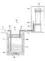
図1は、本実施の形態に係るクリーニング方法及び成膜方法を行うための成膜装置10を概略的に示す縦断面図である。図2は、ローディングエリア40を概略的に示す斜視図である。図3は、ボート44の一例を概略的に示す斜視図である。 FIG. 1 is a longitudinal sectional view schematically showing a
成膜装置10は、載置台(ロードポート)20、筐体30、及び制御部110を有する。 The
載置台(ロードポート)20は、筐体30の前部に設けられている。筐体30は、ローディングエリア(作業領域)40及び成膜容器60を有する。ローディングエリア40は、筐体30内の下方に設けられており、成膜容器60は、筐体30内であってローディングエリア40の上方に設けられている。また、ローディングエリア40と成膜容器60との間には、ベースプレート31が設けられている。なお、後述する供給機構70は、成膜容器60に接続されるように設けられている。 The mounting table (load port) 20 is provided in the front part of the
ベースプレート31は、成膜容器60の後述する反応管61を設置するための例えばSUS製のベースプレートであり、反応管61を下方から上方に挿入するための図示しない開口部が形成されている。 The
載置台(ロードポート)20は、筐体30内へのウェハWの搬入搬出を行うためのものである。載置台(ロードポート)20には、収納容器21、22が載置されている。収納容器21、22は、前面に図示しない蓋を着脱可能に備えた、複数枚例えば50枚程度のウェハWを所定の間隔で収納可能な密閉型収納容器(フープ)である。 The mounting table (load port) 20 is for carrying the wafer W into and out of the
また、載置台20の下方には、後述する移載機構47により移載されたウェハWの外周に設けられた切欠部(例えばノッチ)を一方向に揃えるための整列装置(アライナ)23が設けられていてもよい。 An alignment device (aligner) 23 for aligning notches (for example, notches) provided on the outer periphery of the wafer W transferred by the
ローディングエリア(作業領域)40は、収納容器21、22と後述するボート44との間でウェハWの移載を行い、ボート44を成膜容器60内に搬入(ロード)し、ボート44を成膜容器60から搬出(アンロード)するためのものである。ローディングエリア40には、ドア機構41、シャッター機構42、蓋体43、ボート44、基台45a、45b、昇降機構46、及び移載機構47が設けられている。 The loading area (working area) 40 transfers the wafer W between the
なお、蓋体43及びボート44は、本発明における基板保持部に相当する。 The
ドア機構41は、収納容器21、22の蓋を取外して収納容器21、22内をローディングエリア40内に連通開放するためのものである。 The
シャッター機構42は、ローディングエリア40の上方に設けられている。シャッター機構42は、蓋体43を開けているときに、後述する成膜容器60の開口63から高温の炉内の熱がローディングエリア40に放出されるのを抑制ないし防止するために開口63を覆う(又は塞ぐ)ように設けられている。 The
蓋体43は、保温筒48及び回転機構49を有する。保温筒48は、蓋体43上に設けられている。保温筒48は、ボート44が蓋体43側との伝熱により冷却されることを防止し、ボート44を保温するためのものである。回転機構49は、蓋体43の下部に取り付けられている。回転機構49は、ボート44を回転するためのものである。回転機構49の回転軸は蓋体43を気密に貫通し、蓋体43上に配置された図示しない回転テーブルを回転するように設けられている。 The
昇降機構46は、ボート44のローディングエリア40から成膜容器60に対する搬入、搬出に際し、蓋体43を昇降駆動する。そして、昇降機構46により上昇させられた蓋体43が成膜容器60内に搬入されているときに、蓋体43は、後述する開口63に当接して開口63を密閉するように設けられている。そして、蓋体43に載置されているボート44は、成膜容器60内でウェハWを水平面内で回転可能に保持することができる。 The elevating
なお、成膜装置10は、ボート44を複数有していてもよい。以下、本実施の形態では、図2を参照し、ボート44を2つ有する例について説明する。 The
ローディングエリア40には、ボート44a、44bが設けられている。そして、ローディングエリア40には、基台45a、45b及びボート搬送機構45cが設けられている。基台45a、45bは、それぞれボート44a、44bが蓋体43から移載される載置台である。ボート搬送機構45cは、ボート44a、44bを、蓋体43から基台45a、45bに移載するためのものである。 In the
ボート44a、44bは、例えば石英製であり、大口径例えば直径300mmのウェハWを水平状態で上下方向に所定の間隔(ピッチ幅)で搭載するようになっている。ボート44a、44bは、例えば図3に示すように、天板50と底板51の間に複数本例えば3本の支柱52を介設してなる。支柱52には、ウェハWを保持するための爪部53が設けられている。また、支柱52と共に補助柱54が適宜設けられていてもよい。 The
移載機構47は、収納容器21、22とボート44a、44bの間でウェハWの移載を行うためのものである。移載機構47は、基台57、昇降アーム58、及び、複数のフォーク(移載板)59を有する。基台57は、昇降及び旋回可能に設けられている。昇降アーム58は、ボールネジ等により上下方向に移動可能(昇降可能)に設けられ、基台57は、昇降アーム58に水平旋回可能に設けられている。 The
図4は、成膜容器60の構成の概略を示す断面図である。 FIG. 4 is a cross-sectional view schematically showing the configuration of the
成膜容器60は、例えば、複数枚の被処理基板例えば薄板円板状のウェハWを収容して所定の処理例えばCVD処理等を施すための縦型炉とすることができる。成膜容器60は、反応管61、ヒータ62、供給機構70、密着促進剤供給機構80、パージガス供給機構90、排気機構95及びクリーニングガス供給機構100を有する。 The
なお、ヒータ62は、本発明における加熱機構に相当する。 The
反応管61は、例えば石英製であり、縦長の形状を有しており、下端に開口63が形成されている。ヒータ(加熱装置)62は、反応管61の周囲を覆うように設けられており、反応管61内を所定の温度例えば50〜1200℃に加熱制御可能である。 The
供給機構70は、原料ガス供給部71、及び、成膜容器60内に設けられたインジェクタ72を含む。インジェクタ72は、供給管73aを含む。原料ガス供給部71は、インジェクタ72の供給管73aに接続されている。 The
本実施の形態では、供給機構70は、第1の原料ガス供給部71a及び第2の原料ガス供給部71bを有していてもよい。このとき、第1の原料ガス供給部71a及び第2の原料ガス供給部71bは、それぞれバルブ71c、71dを介し、インジェクタ72(供給管73a)に接続されている。第1の原料ガス供給部71aは、例えばPMDA原料を気化するための第1の気化器74aを有し、PMDAガスを供給することができる。また、第2の原料ガス供給部71bは、例えばODA原料を気化するための第2の気化器74bを有し、ODAガスを供給することができる。 In the present embodiment, the
供給管73aには成膜容器60内に開口する供給孔75が形成されている。インジェクタ72は、原料ガス供給部71から供給管73aを流れる第1の原料ガス及び第2の原料ガスを、供給孔75を介して成膜容器60内に供給する。 A
また、供給管73aは、上下方向に延在するように設けられていてもよい。そして、供給管73aには、複数の供給孔75が形成されていてもよい。なお、供給孔75の形状は、円形、楕円形、矩形等各種の形状であってもよい。 The
インジェクタ72は、内側供給管73bを含むことが好ましい。内側供給管73bは、供給管73aの供給孔75が形成されている部分よりも上流側の部分に収容されていてもよい。そして、内側供給管73bの下流側の端部付近には、供給管73aの内部空間に第1の原料ガス及び第2の原料ガスのいずれか一方の原料ガスを供給するための開口76が形成されていてもよい。このような構造を有する内側供給管73bを含むことによって、第1の原料ガスと第2の原料ガスとを供給孔75から成膜容器60内に供給する前に、予め供給管73aの内部空間において第1の原料ガスと第2の原料ガスとを十分混合させることができる。 The
なお、以下では、供給管73aに第1の原料ガスを供給し、内側供給管73bに第2の原料ガスを供給する場合を例示して、説明する。しかし、内側供給管73bに第1の原料ガスを供給し、供給管73aに第2の原料ガスを供給してもよい。 In the following, a case where the first source gas is supplied to the
また、開口76の形状は、円形、楕円形、矩形等各種の形状であってもよい。 The shape of the opening 76 may be various shapes such as a circle, an ellipse, and a rectangle.
本実施の形態は、ボート44が複数のウェハWを上下方向に所定の間隔で保持する例について説明するものである。このとき、供給管73aとともに、内側供給管73bも、上下方向に延在するように設けられていてもよい。更に、下方側を上流側、上方側を下流側とするときは、内側供給管73bは、供給管73aの供給孔75が形成されている部分よりも下方側の部分において、供給管73aの内部に収容されるように設けられていてもよい。そして、内側供給管73bの上端部付近には、供給管73aの内部空間と連通するための開口76が設けられていてもよい。 In the present embodiment, an example in which the
供給機構70は、例えば供給管73aに第1の原料ガスを流すとともに、内側供給管73bに第2の原料ガスを流す。そして、内側供給管73bを流れる第2の原料ガスを、開口76を介して供給管73aに合流させ、第1の原料ガスと第2の原料ガスとを混合させた状態で、供給孔75を介して成膜容器60内に供給する。 For example, the
図5は、密着促進剤供給機構80の構成を模式的に示す図である。なお、図5では、成膜容器60、ボート44及び密着促進剤供給機構80以外の図示を省略している。 FIG. 5 is a diagram schematically showing the configuration of the adhesion
図5に示すように、密着促進剤供給機構80は、気化器81及び成膜容器60内に設けられた供給管82を含む。気化器81は、バルブ81aを介し、供給管82に接続されている。密着促進剤供給機構80は、密着促進剤を気化させた密着促進剤ガスを成膜容器60内に供給し、ウェハWの表面を密着促進剤ガスにより処理するためのものである。 As shown in FIG. 5, the adhesion
気化器81は、保持容器83、ガス導入部84及びガス導出部85を有する。 The
保持容器83の内部には、例えばシランカップリング剤等の密着促進剤SCが充填可能に設けられている。保持容器83の内部には、加熱機構86が設けられており、保持容器83の内部に充填された密着促進剤SCを、加熱機構86により加熱して気化することができる。なお、加熱機構86としてヒータ等を用いることができる。また、保持容器83を加熱することができればよく、加熱機構86は、保持容器83の任意の場所に設けることができる。 In the holding
ガス導入部84は、保持容器83に、保持容器83で気化した密着促進剤ガスを搬送するための例えば窒素(N2)ガス等の不活性ガスよりなる密着促進剤キャリアガスを、密着促進剤キャリアガス供給部87から導入する。ガス導入部84は、ガス導入管84a及びガス導入口84bを有する。ガス導入管84aは、密着促進剤ガスを搬送する密着促進剤キャリアガスを保持容器83の外部から保持容器83の内部へ導入するための配管である。ガス導入管84aは、保持容器83の上面を貫通するように保持容器83の上面に取り付けられるとともに、保持容器83の内部を上方から下方に延在するように設けられている。また、ガス導入管84aは、一端が保持容器83の底部において開口するとともに、他端が保持容器83の外部で密着促進剤キャリアガス供給部87に接続されている。ガス導入口84bは、ガス導入管84aの下端に形成された開口である。The
図5では、ガス導入口84bが密着促進剤SCの液面よりも下方にあり、ガス導入口84bから供給された密着促進剤キャリアガスが密着促進剤をバブリングする場合を例示している。しかし、ガス導入口84bは、密着促進剤SCの液面よりも上方にあってもよく、ガス導入口84bから供給された密着促進剤キャリアガスが密着促進剤SCをバブリングしなくてもよい。 FIG. 5 illustrates a case where the
ガス導出部85は、保持容器83から、密着促進剤キャリアガスとともに気化した密着促進剤ガスを導出する。ガス導出部85は、ガス導出管85a及びガス導出口85bを有する。ガス導出管85aは、密着促進剤ガスおよび密着促進剤キャリアガスを保持容器83の内部から保持容器83の外部へ導出するための配管である。ガス導出管85aは、保持容器83の上面を貫通するように保持容器83の上面に取り付けられている。また、ガス導出管85aは、一端が保持容器83の内部上方で開口されるように設けられており、他端が成膜容器60の内部に設けられた供給管82に接続されている。ガス導出口85bは、ガス導出管85aの下端に形成された開口である。 The
供給管82は、反応管61の側壁を内側へ貫通して上方向へ屈曲されて延びる石英管よりなる。供給管82の先端には、成膜容器60内に開口する供給孔82aが形成されている。供給管82は、気化器81から供給管82を流れる気化した密着促進剤ガスを、供給孔82aを介して成膜容器60内に供給する。供給孔82aは、ボート44に搭載されたウェハWの近傍に、1箇所設けられているのが好ましい。これにより、供給孔82aより吐出された密着促進剤ガスを、成膜容器60内に一様に拡散させることができる。 The
パージガス供給機構90は、パージガス供給部91、及びパージガス供給管92を含む。パージガス供給部91は、パージガス供給管92を介して成膜容器60に接続されており、成膜容器60内にパージガスを供給する。また、パージガス供給管92の途中には、パージガス供給部91と成膜容器60の内部とを連通又は遮断するためのバルブ93、及び、パージガスの流量を制御するMFC94が設けられている。パージガスとして、窒素(N2)ガスを用いることができる。The purge
排気機構95は、排気装置96及び排気管97を含む。排気機構95は、成膜容器60内から排気管97を介してガスを排気するためのものである。 The
クリーニングガス供給機構100は、クリーニングガス供給部101、及びクリーニングガス供給管102を含む。クリーニングガス供給部101は、クリーニングガス供給管102を介して成膜容器60に接続されており、成膜容器60内にクリーニングガスを供給する。また、クリーニングガス供給管102の途中には、クリーニングガス供給部101と成膜容器60の内部とを連通又は遮断するためのバルブ103、及び、クリーニングガスの流量を制御するMFC104が設けられている。クリーニングガスとして、酸素(O2)ガスを用いることができる。The cleaning
本実施の形態では、クリーニングガス供給機構100からのクリーニングガスの供給流量をMFC104により制御し、パージガス供給機構90からのパージガスの供給流量をMFC94により制御し、成膜容器60からの排気流量を図示しないバルブにより制御する。これにより、成膜容器60内を酸素雰囲気にすることができ、酸素分圧を所定の分圧に調整することができる。 In the present embodiment, the supply flow rate of the cleaning gas from the cleaning
制御部110は、例えば、図示しない演算処理部、記憶部及び表示部を有する。演算処理部は、例えばCPU(Central Processing Unit)を有するコンピュータである。記憶部は、演算処理部に、各種の処理を実行させるためのプログラムを記録した、例えばハードディスクにより構成されるコンピュータ読み取り可能な記録媒体である。表示部は、例えばコンピュータの画面よりなる。演算処理部は、記憶部に記録されたプログラムを読み取り、そのプログラムに従って、ボート44(基板保持部)、ヒータ62、供給機構70、密着促進剤供給機構80、パージガス供給機構90、排気機構95、及びクリーニングガス供給機構100を構成する各部に制御信号を送り、後述するような成膜処理を実行する。 The
次に、本実施の形態に係る成膜装置を用いた成膜処理について説明する。図6は、本実施の形態に係る成膜装置を用いた成膜処理における各工程の手順を説明するためのフローチャートである。 Next, a film forming process using the film forming apparatus according to this embodiment will be described. FIG. 6 is a flowchart for explaining the procedure of each process in the film forming process using the film forming apparatus according to the present embodiment.
成膜処理開始後、ステップS11として、成膜容器60内にウェハWを搬入する(搬入工程)。図1に示した成膜装置10の例では、例えばローディングエリア40において、移載機構47により収納容器21からボート44aへウェハWを搭載し、ウェハWを搭載したボート44aをボート搬送機構45cにより蓋体43に載置することができる。そして、ボート44aを載置した蓋体43を昇降機構46により上昇させて成膜容器60内に搬入することにより、ウェハWを搬入することができる。 After starting the film forming process, in step S11, the wafer W is loaded into the film forming container 60 (carrying-in process). In the example of the
次に、ステップS12では、成膜容器60の内部を減圧する(減圧工程)。排気装置96の排気能力又は排気装置96と排気管97との間に設けられている図示しない流量調整バルブを調整することにより、排気管97を介して成膜容器60を排気する排気量を増大させる。そして、成膜容器60の内部を所定圧力例えば大気圧(760Torr)から例えば0.3Torrに減圧する。 Next, in step S12, the inside of the
次に、ステップS13では、ウェハWの温度を、ウェハWにポリイミド膜を成膜するときの所定温度(成膜温度)まで上昇させる(リカバリ工程)。ボート44aを成膜容器60の内部に搬入した後、ヒータ62に電力を供給することによって、ボート44aに搭載されているウェハWの温度を成膜温度まで上昇させる。 Next, in step S13, the temperature of the wafer W is raised to a predetermined temperature (deposition temperature) when a polyimide film is formed on the wafer W (recovery step). After the
本実施の形態では、リカバリ工程において、ウェハWの表面を密着促進剤により処理してもよい。このとき、ヒータ62によりウェハWを加熱するとともに、密着促進剤供給機構80により成膜容器60内に密着促進剤ガスを供給し、供給された密着促進剤ガスと、加熱されているウェハWとを、水分を含まない雰囲気中で反応させることによって、ウェハWの表面を処理する(表面処理工程)。 In the present embodiment, the surface of the wafer W may be treated with an adhesion promoter in the recovery process. At this time, the wafer W is heated by the
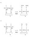
図7は、密着促進剤としてシランカップリング剤を用いたときのウェハWの表面における反応を示す図である。 FIG. 7 is a diagram showing a reaction on the surface of the wafer W when a silane coupling agent is used as the adhesion promoter.
シランカップリング剤として、分子中に例えばアルコキシ基(RO−(R;アルキル基))を有するオルガノシランを用いることが好ましい。図7では、分子中に例えばメトキシ基(CH3O−)を有するオルガノシランを用いた例を示す。そして、図7(a)に示すように、表面が水酸基すなわちヒドロキシ基(−OH)で終端されたSiウェハを用いるときは、シランカップリング剤のメトキシ基が、ウェハ表面のヒドロキシ基と熱反応してメタノール(CH3OH)が生成することによって、ウェハ表面に吸着する。また、図7(b)に示すように、表面が水素原子(H)で終端されたSiウェハを用いるときは、シランカップリング剤のメトキシ基が、ウェハ表面の水素原子と熱反応してメタン(CH4)が生成することによって、ウェハ表面に吸着する。As the silane coupling agent, for example, organosilane having an alkoxy group (RO- (R; alkyl group)) in the molecule is preferably used. FIG. 7 shows an example in which an organosilane having, for example, a methoxy group (CH3 O—) in the molecule is used. As shown in FIG. 7A, when a Si wafer having a surface terminated with a hydroxyl group, that is, a hydroxy group (—OH) is used, the methoxy group of the silane coupling agent reacts with the hydroxyl group on the wafer surface in a thermal reaction. Then, methanol (CH3 OH) is generated and adsorbed on the wafer surface. Further, as shown in FIG. 7B, when a Si wafer having a surface terminated with hydrogen atoms (H) is used, the methoxy group of the silane coupling agent reacts with the hydrogen atoms on the wafer surface to react with methane. When (CH4 ) is generated, it is adsorbed on the wafer surface.
オルガノシランとして、下記式(1) As organosilane, the following formula (1)

リカバリ工程とともに行う表面処理工程では、気化器81において例えばSC剤A又はSC剤Bよりなる密着促進剤を気化させ、気化した密着促進剤ガスを供給管82に形成された供給孔82aを介して成膜容器60内に供給する。例えばSC剤Aを用いるときは、加熱機構86により保持容器83の温度を例えば150℃に加熱することによって、0.3g/分の気化量を得ることができる。また、例えばSC剤Bを用いるときは、加熱機構86により保持容器83の温度を例えば100℃に加熱することによって、0.3g/分の気化量を得ることができる。なお、このとき、密着促進剤キャリアガスであるN2ガスを例えば0.1slmの流量で導入してもよく、全く導入しなくてもよい。In the surface treatment step performed together with the recovery step, an adhesion promoter made of, for example, SC agent A or SC agent B is vaporized in the
次に、ステップS14では、ポリイミド膜を成膜する(成膜工程)。 Next, in step S14, a polyimide film is formed (film formation process).
制御部110により、供給管73aに第1の原料ガスを流す第1の流量F1と、内側供給管73bに第2の原料ガスを流す第2の流量F2とを予め設定しておく。そして、回転機構49によりウェハWを回転させた状態で、設定した第1の流量F1で第1の原料ガス供給部71aから第1の原料ガスを供給管73aに流し、設定した第2の流量F2で第2の原料ガス供給部71bから第2の原料ガスを内側供給管73bに流すことによって、第1の原料ガスと第2の原料ガスとを所定の混合比で混合させた状態で成膜容器60内に供給する。そして、ウェハWの表面でPMDAとODAを重合反応させ、ポリイミド膜を成膜する。具体的には、例えば第1の流量F1を900sccmとし、第2の流量F2を900sccmとすることができる。 The
このときの、PMDAとODAとの重合反応は、次の式(3)に従う。 The polymerization reaction of PMDA and ODA at this time follows the following formula (3).
バルブ71cを閉じ、第1の原料ガス供給部71aからの第1の原料ガスの供給を停止する。また、バルブ71dを閉じ、第2の原料ガス供給部71bからの第2の原料ガスの供給を停止する。そして、パージガス供給機構90と排気機構95とを制御することにより、成膜容器60の内部の原料ガスをパージガスに置換する。 The
例えば、排気装置96の排気能力又は排気装置96と排気管97との間に設けられている図示しない流量調整バルブを調整して排気量を増やすことにより、成膜容器60の内部を例えば0.3Torrに減圧する。その後、排気量を減少させるか、又は排気量を0にして排気を停止した状態で、成膜容器60内の内部の圧力が例えば5.0Torrになるまで、バルブ93を開いてパージガス供給機構90によりパージガスを成膜容器60内に供給する。これにより、成膜容器60内の原料ガスをパージガスに置換できる。また、排気機構95による減圧と、パージガス供給機構90によるパージガスの供給とを1回行った後、更に減圧とパージガスの供給を複数回繰り返してもよい。これにより、成膜容器60内の原料ガスを、更に確実にパージガスに置換できる。 For example, by adjusting the exhaust capacity of the
本実施の形態では、パージ工程において、ウェハW上に成膜されたポリイミド膜をヒータ62により熱処理してもよい。熱処理は、成膜後、膜中のイミド化していない部分をイミド化するために行う。ポリイミドは高い絶縁性を有するため、膜中のポリイミドの割合であるイミド化率を上昇させることによって、成膜したポリイミド膜の絶縁性を向上させることができる。 In the present embodiment, the polyimide film formed on the wafer W may be heat-treated by the
次に、ステップS16では、成膜容器60の内部を大気圧に復圧する(復圧工程)。排気装置96の排気能力又は排気装置96と排気管97との間に設けられている図示しない流量調整バルブを調整することにより、成膜容器60を排気する排気量を減少させ、成膜容器60の内部を例えば0.3Torrから例えば大気圧(760Torr)に復圧する。 Next, in step S16, the inside of the
なお、ポリイミド膜の熱処理は、ポリイミド膜を成膜した後、後述する搬出工程の前に、成膜容器60の内部で行えばよく、復圧工程の際、又は、復圧工程の後に行ってもよい。 The heat treatment of the polyimide film may be performed inside the
次に、ステップS17では、成膜容器60からウェハWを搬出する(搬出工程)。図1に示した成膜装置10の例では、例えばボート44aを載置した蓋体43を昇降機構46により下降させて成膜容器60内からローディングエリア40に搬出することができる。そして、移載機構47により、搬出した蓋体43に載置されているボート44aから収納容器21へウェハWを移載することによって、ウェハWを成膜容器60から搬出することができる。 Next, in step S17, the wafer W is unloaded from the film forming container 60 (unloading step). In the example of the
なお、複数のバッチについて連続して成膜処理を行うときは、更に、ローディングエリア40において、移載機構47により収納容器21からウェハWをボート44へ移載し、再びステップS11に戻り、次のバッチの成膜処理を行う。 In addition, when the film forming process is continuously performed for a plurality of batches, the wafer W is transferred from the
このように、ステップS11(搬入工程)からステップS17(搬出工程)までを行うことにより、あるバッチについて成膜処理を行うことができる。なお、ステップS11(搬入工程)からステップS17(搬出工程)までの工程は、本発明における処理工程に相当する。 In this way, by performing steps S11 (carrying-in process) to S17 (carrying-out process), a film forming process can be performed for a certain batch. In addition, the process from step S11 (carry-in process) to step S17 (carry-out process) is equivalent to the process process in this invention.
次に、ステップS18では、成膜容器60内に残留しているポリイミドを酸化して除去する(クリーニング工程)。 Next, in step S18, the polyimide remaining in the
前述したように、クリーニングガス供給機構100により、酸素ガスよりなるクリーニングガスを成膜容器60内に供給する。このとき、クリーニングガス供給機構100からのクリーニングガスの供給流量をMFC104により制御し、パージガス供給機構90からのパージガスの供給流量をMFC94により制御し、成膜容器60からの排気流量を図示しないバルブにより制御する。これにより、成膜容器60内を酸素雰囲気にすることができ、酸素分圧を所定の分圧に調整することができる。 As described above, the cleaning
このようにして成膜容器60内を酸素雰囲気にした状態で、ヒータ62により、成膜容器60を加熱する。ここで、成膜容器60を360〜540℃の温度に加熱することによって、成膜容器60内に付着したポリイミド膜あるいは付着したポリイミド膜が剥がれ落ちたものを含め、成膜容器60内に残留しているポリイミドを酸化して除去する。これにより、後述するように、成膜容器60内に残留しているポリイミドが熱分解により炭化することを防止できる。 In this way, the
また、成膜容器60内を、酸素分圧が0.2気圧以上である酸素雰囲気にした状態で、ヒータ62により、成膜容器60を加熱することが好ましい。これにより、成膜容器60内に残留しているポリイミドがより酸化しやすくなるため、熱分解により炭化することをより防止できる。 Further, it is preferable that the
なお、処理工程(ステップS11〜ステップS17)を複数回繰り返して行うときは、処理工程とクリーニング工程(ステップS18)とを交互に繰り返してもよい。これにより、次の処理工程を行う前に、成膜容器内に残留しているポリイミドを常に酸化して除去することができる。 In addition, when performing a process process (step S11-step S17) repeatedly several times, you may repeat a process process and a cleaning process (step S18) alternately. Thereby, before performing the next processing step, the polyimide remaining in the film formation container can be always oxidized and removed.
あるいは、処理工程(ステップS11〜ステップS17)を所定回数繰り返した後に、クリーニング工程(ステップS18)を1回行うようにしてもよい。そして、処理工程を繰り返す所定回数を、クリーニング工程の直前の処理工程において成膜処理されるウェハに付着するパーティクルの数が、所定の上限値を超えないように設定することにより、成膜容器60内をクリーニングしつつ、成膜処理の時間を短縮することができる。 Alternatively, the cleaning process (step S18) may be performed once after the processing process (steps S11 to S17) is repeated a predetermined number of times. Then, by setting the predetermined number of times to repeat the processing step so that the number of particles adhering to the wafer subjected to the film forming process in the processing step immediately before the cleaning step does not exceed a predetermined upper limit value, the
このようにして、処理工程とクリーニング工程を行った後、成膜処理を終了する。 In this way, after performing the treatment process and the cleaning process, the film formation process is terminated.
次に、本実施の形態におけるクリーニングによれば、ポリイミドの炭化を防止でき、成膜容器内にパーティクルが残ることなくポリイミドを除去することができることについて説明する。 Next, it will be described that according to the cleaning in this embodiment, the carbonization of polyimide can be prevented and the polyimide can be removed without particles remaining in the film formation container.
図8は、ポリイミドが熱分解する様子又はポリイミドが酸化する様子を示す図である。図8(a)は、ポリイミドが熱分解する様子を示し、図8(b)は、ポリイミドが酸化する様子を示す。 FIG. 8 is a diagram showing a state where polyimide is thermally decomposed or a state where polyimide is oxidized. FIG. 8A shows a state where polyimide is thermally decomposed, and FIG. 8B shows a state where polyimide is oxidized.
成膜容器中を酸素雰囲気にしない状態、すなわち例えば窒素雰囲気にした状態で、ヒータ62により成膜容器60を加熱する場合を考える。すると、図8(a)に示すように、熱エネルギーによりポリイミドの分子中の各所で化学結合が切られ、ポリイミドは熱分解する。この際に、ポリイミドの分子中の炭素原子の一部が炭化して煤状になって残る。 Consider a case where the
一方、成膜容器60中を酸素雰囲気にした状態で、ヒータ62により成膜容器60を加熱する場合を考える。すると、図8(b)に示すように、ポリイミドの分子中の炭素原子は酸素と化合、すなわち酸化して例えば二酸化炭素(CO2)となって気化するため、ポリイミドは除去される。On the other hand, consider a case where the
図9は、昇温脱離法(Temperature Programmed Desorption;TPD)によりポリイミドを昇温しながらガス脱離(発生)させ、発生したガスの量(発生量)を質量分析法(Mass Spectrometry;MS)により計測した結果を示すグラフである。図9(a)のグラフは、酸素分圧が20%、すなわち0.2気圧の結果を示し、図9(b)のグラフは、酸素分圧が0%、すなわち0気圧の結果を示す。 FIG. 9 shows the mass desorption (generation) of gas generated while the polyimide is heated by temperature programmed desorption (TPD), and the amount of gas generated (generated) is mass spectrometry (MS). It is a graph which shows the result measured by this. The graph of FIG. 9A shows the result when the oxygen partial pressure is 20%, that is, 0.2 atm, and the graph of FIG. 9B shows the result when the oxygen partial pressure is 0%, that is, 0 atm.
図9(b)に示すように、酸素分圧が0%すなわち0気圧であるときは、温度上昇に伴って、490℃で二酸化炭素(CO2)ガスの発生が始まるものの、近い温度である540℃でアニリン又はフェノール等の有機化合物と推定されるガス(有機化合物ガス)の発生が始まる。また、有機化合物ガスの発生量に対するCO2ガス及び一酸化炭素(CO)ガスの発生量は、相対的に小さい。また、この条件は、明らかにクリーニング工程の後、煤状のパーティクルが成膜容器60内に残る条件であり、ポリイミドの熱分解反応が発生する条件である。As shown in FIG. 9B, when the oxygen partial pressure is 0%, that is, 0 atm, the generation of carbon dioxide (CO2 ) gas starts at 490 ° C. as the temperature rises, but the temperature is close. Generation of a gas (organic compound gas) presumed to be an organic compound such as aniline or phenol starts at 540 ° C. Further, the generation amount of CO2 gas and carbon monoxide (CO) gas with respect to the generation amount of the organic compound gas is relatively small. Further, this condition is a condition that apparently the soot-like particles remain in the
一方、図9(a)に示すように、酸素分圧が20%すなわち0.2気圧であるときは、温度上昇に伴って、360℃でCO2ガスの発生が始まるものの、有機化合物ガスの発生は、580℃までは始まらない。また、有機化合物ガスの発生量に対するCO2ガス及びCOガスの発生量は、相対的に小さい。On the other hand, as shown in FIG. 9A, when the oxygen partial pressure is 20%, that is, 0.2 atmospheric pressure, the generation of CO2 gas starts at 360 ° C. as the temperature rises. Development does not begin until 580 ° C. In addition, the amount of CO2 gas and CO gas generated relative to the amount of organic compound gas generated is relatively small.
更に、酸素分圧を20%以上にしたときも、図9(a)と略同様の傾向を示す。従って、酸素分圧が20%すなわち0.2気圧以上の酸素雰囲気にした状態で、360〜540℃の温度に加熱することによって、有機化合物に熱分解させることなくポリイミドを酸化して除去することができる。 Furthermore, when the oxygen partial pressure is set to 20% or more, a tendency similar to that shown in FIG. Therefore, by heating to a temperature of 360 to 540 ° C. in an oxygen atmosphere with an oxygen partial pressure of 20%, that is, 0.2 atmospheres or more, the polyimide is oxidized and removed without thermally decomposing into an organic compound. Can do.
ただし、温度範囲は、成膜容器の構成、ポリイミド膜の成膜条件等に依存するため、上記した条件に限られるものではない。例えば、540〜700℃の温度に加熱する場合であっても、酸素分圧が40%すなわち0.4気圧よりも大きい状態で行うときは、有機化合物に熱分解させることなくポリイミドを酸化して除去することができる。 However, the temperature range depends on the configuration of the film formation container, the film formation conditions of the polyimide film, and the like, and is not limited to the above-described conditions. For example, even when heating to a temperature of 540 to 700 ° C., when the oxygen partial pressure is higher than 40%, that is, greater than 0.4 atm, the polyimide is oxidized without thermally decomposing into an organic compound. Can be removed.
また、酸素分圧が100%すなわち1気圧であることが好ましい。これにより、成膜容器内を大気圧より増加させることなく、ポリイミドを酸化して除去することができる。 The oxygen partial pressure is preferably 100%, that is, 1 atmosphere. Thereby, polyimide can be oxidized and removed without increasing the inside of the film formation container from atmospheric pressure.
更に、本実施の形態では、前述したように、密着促進剤によりウェハWの表面を処理する表面処理工程を行う場合でも、成膜容器内にパーティクルが残ることなくポリイミド及び密着促進剤を酸化して除去することができる。 Furthermore, in the present embodiment, as described above, even when the surface treatment process for treating the surface of the wafer W with the adhesion promoter is performed, the polyimide and the adhesion promoter are oxidized without leaving particles in the film formation container. Can be removed.
ここで、複数回成膜処理を行って、密着促進剤SCとポリイミド膜PIが複数積層された積層体も、本実施の形態におけるクリーニング方法により酸化して除去できるか否かの評価を行った。評価用サンプルとして、成膜容器に代え、ウェハW上に、密着促進剤SCとポリイミド膜PIが複数積層された積層体LMが形成されたものを用いた。図10は、積層体LMが形成されたウェハWのクリーニング処理の前後の状態を示す断面図である。 Here, a plurality of film formation processes were performed, and it was evaluated whether or not a stacked body in which a plurality of adhesion promoters SC and polyimide films PI were stacked can be oxidized and removed by the cleaning method in the present embodiment. . As a sample for evaluation, a sample in which a laminated body LM in which a plurality of adhesion promoters SC and polyimide films PI are laminated is used on the wafer W instead of the film forming container. FIG. 10 is a cross-sectional view illustrating a state before and after the cleaning process of the wafer W on which the stacked body LM is formed.
一例として、SiウェハよりなるウェハWを200℃に保持した状態で、前述したSC剤Aを150℃に加熱して0.3g/分の流量でSiウェハWに供給し、600秒間表面処理を行った。その上に、膜厚250nmのポリイミド膜PIを成膜した。そして、更に、密着促進剤SCによる表面処理、ポリイミド膜PIの成膜、密着促進剤SCによる表面処理の順に繰り返すことによって、図10の左側に示すように積層体LMが形成されたウェハWを得た。 As an example, with the wafer W made of Si wafer held at 200 ° C., the SC agent A described above is heated to 150 ° C. and supplied to the Si wafer W at a flow rate of 0.3 g / min, and surface treatment is performed for 600 seconds. went. A polyimide film PI having a thickness of 250 nm was formed thereon. Further, by repeating the surface treatment with the adhesion promoter SC, the formation of the polyimide film PI, and the surface treatment with the adhesion promoter SC, the wafer W on which the laminate LM is formed as shown on the left side of FIG. Obtained.
このウェハWに対し、酸素分圧100%すなわち1気圧になるように、酸素ガスの流量及び成膜容器からの排気流量を調整した。例えば、酸素ガスの流量を30slmとした。そして、700℃で120分間クリーニング処理を行った。クリーニング処理後のウェハWの表面を、走査型電子顕微鏡(Scanning Electron Microscope)により観察したところ、パーティクル等は残っていないことが確認された。 The flow rate of oxygen gas and the exhaust gas flow rate from the film formation container were adjusted so that the partial pressure of oxygen was 100%, that is, 1 atm. For example, the flow rate of oxygen gas was 30 slm. Then, a cleaning process was performed at 700 ° C. for 120 minutes. When the surface of the wafer W after the cleaning treatment was observed with a scanning electron microscope, it was confirmed that no particles or the like remained.
以上、本実施の形態によれば、ポリイミド膜を成膜する成膜装置において、成膜容器内を酸素雰囲気にした状態で、成膜容器を加熱機構により加熱することによって、成膜容器内に残留しているポリイミドを酸化して除去する。これにより、成膜容器内にパーティクルが残ることなく密着促進剤を含めたポリイミドを除去することができる。また、ポリイミド膜の成膜処理と密着促進剤による表面処理とを繰り返してなる積層体が形成されている場合でも、成膜容器内にパーティクルが残ることなく密着促進剤とポリイミドとを除去することができる。
(第2の実施の形態)
次に、図11から図13を参照し、本発明の第2の実施の形態に係るクリーニング方法及び成膜方法について説明する。As described above, according to the present embodiment, in the film forming apparatus for forming the polyimide film, the film forming container is heated by the heating mechanism in the state where the film forming container is in an oxygen atmosphere. The remaining polyimide is oxidized and removed. Thereby, the polyimide including the adhesion promoter can be removed without particles remaining in the film formation container. In addition, even when a laminate is formed by repeating the film formation process of the polyimide film and the surface treatment with the adhesion promoter, the adhesion promoter and the polyimide should be removed without particles remaining in the film formation container. Can do.
(Second Embodiment)
Next, a cleaning method and a film forming method according to the second embodiment of the present invention will be described with reference to FIGS.
本実施の形態に係るクリーニング方法及び成膜方法を行うための成膜装置は、成膜容器が枚葉処理を行うためのものであるとともに、成膜容器とは別に表面処理のための処理容器を有している点で、第1の実施の形態に係る成膜方法を行うための成膜装置と相違する。 A film forming apparatus for performing a cleaning method and a film forming method according to the present embodiment is for a film forming container to perform single wafer processing, and a processing container for surface treatment separately from the film forming container. It differs from the film-forming apparatus for performing the film-forming method according to the first embodiment.
図11は、本実施の形態に係るクリーニング方法及び成膜方法を行うための成膜装置120を概略的に示す平面図である。図12は、処理容器130、密着促進剤供給機構80及び排気機構95aの構成を示す正面図である。図13は、成膜容器60b、供給機構70及び排気機構95bの構成を示す平面図である。 FIG. 11 is a plan view schematically showing a
図11に示すように、本実施の形態に係る成膜装置120は、ポート121A〜121C、ローダ122、ロードロック123A、123B、搬送室124、複数の表面処理部125、及び成膜部126を有する。 As shown in FIG. 11, the
ポート121A〜121Cには、ローダ122が接続されている。ローダ122には、ロードロック123A、123Bが接続されている。ロードロック123A、123Bには、搬送室124が接続されている。搬送室124には、表面処理部125が2つ接続されており、成膜部126が1つ接続されている。また、搬送室124には、ウェハをロードロック123A、123Bと表面処理部125及び成膜部126との間で搬送するための搬送アーム124aが設けられている。 A
なお、表面処理部125と成膜部126の数は、特に限定されるものではなく、スループットを向上させるために、表面処理及び成膜処理の条件に応じて、任意の数に変更可能である。 Note that the number of the
図11及び図12に示すように、表面処理部125は、処理容器130と、密着促進剤供給機構80及び排気機構95aとを有する。 As shown in FIGS. 11 and 12, the
密着促進剤供給機構80は、気化器81及び供給管82を含み、供給管82が処理容器130内に設けられている点を除き、第1の実施の形態に係る密着促進剤供給機構80と同様にすることができる。また、排気機構95aは、排気装置96及び排気管97を含み、第1の実施の形態に係る成膜容器60に設けられた排気機構95と同様にすることができる。 The adhesion
処理容器130は、処理室131、ヒータ(加熱装置)132、基板保持部133及び排気機構95aを有する。ヒータ(加熱装置)132は、表面処理の際にウェハWを加熱するためのものである。基板保持部133は、ウェハWを保持するためのものである。ただし、基板保持部133は、ウェハWを1枚保持可能に設けられている。なお、ヒータ(加熱装置)132は、基板保持部133内に設けられていてもよい。 The
図13に示すように、成膜部126は、成膜容器60b、供給機構70、パージガス供給機構90、排気機構95b及びクリーニングガス供給機構100を有する。パージガス供給機構90は、パージガス供給部91、パージガス供給管92、バルブ93及びMFC94を含み、第1の実施の形態におけるパージガス供給機構90と同様にすることができる。排気機構95bは、排気装置96及び排気管97を含み、第1の実施の形態における排気機構95と同様にすることができる。クリーニングガス供給機構100は、クリーニングガス供給部101、及びクリーニングガス供給管102、バルブ103及びMFC104を含み、第1の実施の形態におけるクリーニングガス供給機構100と同様にすることができる。 As shown in FIG. 13, the
成膜容器60bは、反応室61、ヒータ(加熱装置)62及び基板保持部44cを有する。基板保持部44cは、ウェハWを保持可能であってかつ回転可能に設けられている。ただし、基板保持部44cは、ウェハWを1枚保持可能に設けられている。 The
供給機構70は、第1の原料ガス供給部71a、第2の原料ガス供給部71b、インジェクタ72を含む。第1の原料ガス供給部71a、第2の原料ガス供給部71bは第1の実施の形態と同様にすることができる。 The
インジェクタ72は、供給管73a及び内側供給管73bを含む。原料ガス供給部71は、インジェクタ72の供給管73aに接続されている。供給管73aと内側供給管73bとは、水平方向に延在するように設けられている点を除き、第1の実施の形態に係るインジェクタ72と同様にすることができる。すなわち、供給管73aには、複数の供給孔75が形成されている。内側供給管73bの下流側の端部付近には、供給管73aの内部空間に第1の原料ガスを供給するための開口76が形成されている。 The
なお、図13では、内側供給管73bに第1の原料ガス供給部71aから第1の原料ガスを供給し、供給管73aに第2の原料ガス供給部71bから第2の原料ガスを供給する例を示している。しかし、供給管73aに第1の原料ガスを供給し、内側供給管73bに第2の原料ガスを供給してもよい。 In FIG. 13, the first source gas is supplied from the first source
また、制御部110は、第1の実施の形態と同様にすることができる。 Moreover, the
本実施の形態に係る成膜処理では、成膜部126により成膜処理を行う前に、表面処理部125を用いて密着促進剤による表面処理を行う。 In the film forming process according to this embodiment, before the
搬送室124に設けられた搬送アーム124aによりウェハWを表面処理部125の処理容器130内に設けられた基板保持部133に受け渡し、ウェハWを保持する。そして、排気機構95aにより、処理容器130の内部を減圧する。 The wafer W is transferred to the
次に、制御部110によりヒータ132に供給する電力を制御することによって、ウェハWの温度を表面処理するための処理温度まで上昇させる。そして、ウェハWを加熱するとともに、処理容器130内に密着促進剤ガスを供給し、供給された密着促進剤ガスと、加熱されているウェハWとを、水分を含まない雰囲気中で反応させることによって、ウェハWの表面を処理する(表面処理工程)。 Next, by controlling the power supplied to the
本実施の形態でも、密着促進剤としてシランカップリング剤を用いることが好ましい。また、本実施の形態でも、シランカップリング剤として、分子中に例えばアルコキシ基を有するオルガノシランを用いることが好ましい。オルガノシランとして、式(1)、式(2)に示したSC剤A、SC剤Bを用いることが好ましい。また、SC剤Aを用いることにより、表面が水素原子(H)で終端されたSiウェハを用いるときも、成膜されたポリイミド膜の密着性を向上させることができる。 Also in this embodiment, it is preferable to use a silane coupling agent as the adhesion promoter. Also in this embodiment, it is preferable to use organosilane having, for example, an alkoxy group in the molecule as the silane coupling agent. As organosilane, it is preferable to use SC agent A and SC agent B shown in formulas (1) and (2). Further, by using the SC agent A, the adhesion of the formed polyimide film can be improved even when a Si wafer whose surface is terminated with hydrogen atoms (H) is used.
このようにして表面処理部125を用いて密着促進剤による表面処理を行った後、成膜部126により成膜処理を行う。成膜部126により成膜処理は、成膜処理がバッチ処理に代え枚葉処理である点を除き、第1の実施の形態の成膜工程と同様にすることができる。 After performing the surface treatment with the adhesion promoter using the
そして、本実施の形態でも、成膜処理の後、成膜容器60b内に残留しているポリイミドを酸化して除去する(クリーニング工程)。 Also in this embodiment, after the film forming process, the polyimide remaining in the
第1の実施の形態と同様に、クリーニングガス供給機構100により、酸素ガスよりなるクリーニングガスを成膜容器60b内に供給する。このとき、クリーニングガス供給機構100からのクリーニングガスの供給流量をMFC104により制御し、パージガス供給機構90からのパージガスの供給流量をMFC94により制御し、成膜容器60bからの排気流量を図示しないバルブにより制御する。これにより、成膜容器60b内を酸素雰囲気にすることができ、酸素分圧を所定の分圧に調整することができる。 As in the first embodiment, the cleaning
このようにして成膜容器60b内を酸素雰囲気にした状態で、ヒータ62により、成膜容器60bを加熱する。ここで、成膜容器60bを360〜540℃の温度に加熱することによって、成膜容器60b内に付着したポリイミド膜あるいは付着したポリイミド膜が剥がれ落ちたものを含め、成膜容器60b内に残留しているポリイミドを酸化して除去する。これにより、成膜容器60b内に残留しているポリイミドが熱分解により炭化することを防止できる。 In this way, the
また、成膜容器60b内を、酸素分圧が0.2気圧以上である酸素雰囲気にした状態で、ヒータ62により、成膜容器60bを加熱することが好ましい。これにより、成膜容器60b内に残留しているポリイミドがより酸化しやすくなるため、熱分解により炭化することをより防止できる。 In addition, it is preferable that the
本実施の形態でも、ポリイミド膜を成膜する成膜装置において、成膜容器内を酸素雰囲気にした状態で、成膜容器を加熱機構により加熱することによって、成膜容器内に残留しているポリイミドを酸化して除去する。これにより、成膜容器内にパーティクルが残ることなくポリイミド及び密着促進剤を酸化して除去することができる。 Also in this embodiment mode, in the film formation apparatus for forming a polyimide film, the film formation container remains in the film formation container by heating the film formation container with a heating mechanism in an oxygen atmosphere. The polyimide is oxidized and removed. Thereby, the polyimide and the adhesion promoter can be oxidized and removed without particles remaining in the film formation container.
以上、本発明の好ましい実施の形態について記述したが、本発明はかかる特定の実施の形態に限定されるものではなく、特許請求の範囲内に記載された本発明の要旨の範囲内において、種々の変形・変更が可能である。 The preferred embodiments of the present invention have been described above, but the present invention is not limited to such specific embodiments, and various modifications can be made within the scope of the gist of the present invention described in the claims. Can be modified or changed.
10 成膜装置
43 蓋体(基板保持部)
44、44a、44b ボート(基板保持部)
60 成膜容器
62 ヒータ
70 供給機構
71 原料ガス供給部
80 密着促進剤供給機構
90 パージガス供給機構
95 排気機構
100 クリーニングガス供給機構
110 制御部
W ウェハ10
44, 44a, 44b Boat (substrate holding part)
60
Claims (8)
Translated fromJapanese前記成膜容器内を酸素雰囲気にした状態で、前記成膜容器を加熱機構により360〜540℃の温度に加熱することによって、前記成膜容器内に残留しているポリイミドを酸化して除去する、クリーニング方法。Supplying the first source gas obtained by vaporizing the first raw material made of acid dianhydride and the second source gas obtained by vaporizing the second raw material made of diamine into the film formation container, A cleaning method in a film forming apparatus for forming a polyimide film on a substrate carried into a film forming container,
The polyimide film remaining in the film formation container is oxidized and removed by heating the film formation container to a temperature of 360 to 540 ° C. with a heating mechanism in an oxygen atmosphere in the film formation container. Cleaning method.
基板を前記成膜容器内に搬入し、密着促進剤を気化させた密着促進剤ガスを前記成膜容器内に供給し、前記成膜容器内に搬入した前記基板の表面を密着促進剤ガスにより処理し、酸二無水物よりなる第1の原料を気化させた第1の原料ガスと、ジアミンよりなる第2の原料を気化させた第2の原料ガスとを前記成膜容器内に供給することによって、密着促進剤により表面を処理した前記基板にポリイミド膜を成膜し、ポリイミド膜を成膜した前記基板を前記成膜容器内から搬出する処理工程と、
前記成膜容器内を酸素雰囲気にした状態で、前記成膜容器を加熱機構により加熱することによって、前記成膜容器内に残留しているポリイミドを酸化して除去するクリーニング工程と
を有する、成膜方法。In a film forming method for forming a film on the substrate carried into the film forming container by supplying a source gas into the film forming container,
A substrate is carried into the film formation container, an adhesion promoter gas vaporized from the adhesion promoter is supplied into the film formation container, and the surface of the substrate carried into the film formation container is exposed to the adhesion promoter gas. A first source gas obtained by vaporizing a first raw material made of acid dianhydride and a second raw material gas vaporizing a second raw material made of diamine is supplied into the film formation container. A process of forming a polyimide film on the substrate whose surface has been treated with an adhesion promoter, and carrying out the substrate on which the polyimide film has been formed from the film formation container;
A cleaning step of oxidizing and removing polyimide remaining in the film-forming container by heating the film-forming container with a heating mechanism in an oxygen atmosphere inside the film-forming container. Membrane method.
複数の基板を上下方向に所定の保持間隔で保持している基板保持部を前記成膜容器内に搬入することによって、前記複数の基板を前記成膜容器内に搬入するものであり、
前記基板保持部を前記成膜容器内から搬出することによって、ポリイミド膜を成膜した前記複数の基板を前記成膜容器内から搬出するものである、請求項3から請求項5のいずれかに記載の成膜方法。The processing step includes
Carrying the plurality of substrates into the film-forming container by carrying a substrate holding unit holding the plurality of substrates in the vertical direction at a predetermined holding interval into the film-forming container;
The substrate according to any one of claims 3 to 5, wherein the plurality of substrates on which the polyimide film has been formed are unloaded from the inside of the film forming container by unloading the substrate holding unit from the inside of the film forming container. The film-forming method of description.
Priority Applications (4)
| Application Number | Priority Date | Filing Date | Title |
|---|---|---|---|
| JP2011073192AJP2012209393A (en) | 2011-03-29 | 2011-03-29 | Cleaning method and deposition method |
| TW101109641ATW201245282A (en) | 2011-03-29 | 2012-03-21 | Cleaning method and film depositing method |
| KR1020120029164AKR20120112054A (en) | 2011-03-29 | 2012-03-22 | Cleaning method and film deposition method |
| US13/429,564US20120269970A1 (en) | 2011-03-29 | 2012-03-26 | Cleaning method and film depositing method |
Applications Claiming Priority (1)
| Application Number | Priority Date | Filing Date | Title |
|---|---|---|---|
| JP2011073192AJP2012209393A (en) | 2011-03-29 | 2011-03-29 | Cleaning method and deposition method |
Publications (1)
| Publication Number | Publication Date |
|---|---|
| JP2012209393Atrue JP2012209393A (en) | 2012-10-25 |
Family
ID=47021540
Family Applications (1)
| Application Number | Title | Priority Date | Filing Date |
|---|---|---|---|
| JP2011073192APendingJP2012209393A (en) | 2011-03-29 | 2011-03-29 | Cleaning method and deposition method |
Country Status (4)
| Country | Link |
|---|---|
| US (1) | US20120269970A1 (en) |
| JP (1) | JP2012209393A (en) |
| KR (1) | KR20120112054A (en) |
| TW (1) | TW201245282A (en) |
Cited By (1)
| Publication number | Priority date | Publication date | Assignee | Title |
|---|---|---|---|---|
| JP2015099808A (en)* | 2013-11-18 | 2015-05-28 | 東京エレクトロン株式会社 | Cleaning method for polyimide film formation device |
Families Citing this family (32)
| Publication number | Priority date | Publication date | Assignee | Title |
|---|---|---|---|---|
| TWI529808B (en) | 2010-06-10 | 2016-04-11 | Asm國際股份有限公司 | Method for selectively depositing film on substrate |
| US9112003B2 (en) | 2011-12-09 | 2015-08-18 | Asm International N.V. | Selective formation of metallic films on metallic surfaces |
| JP6111171B2 (en)* | 2013-09-02 | 2017-04-05 | 東京エレクトロン株式会社 | Film forming method and film forming apparatus |
| TWI661072B (en) | 2014-02-04 | 2019-06-01 | 荷蘭商Asm Ip控股公司 | Selective deposition of metals, metal oxides, and dielectrics |
| US10047435B2 (en) | 2014-04-16 | 2018-08-14 | Asm Ip Holding B.V. | Dual selective deposition |
| US9490145B2 (en) | 2015-02-23 | 2016-11-08 | Asm Ip Holding B.V. | Removal of surface passivation |
| US10428421B2 (en) | 2015-08-03 | 2019-10-01 | Asm Ip Holding B.V. | Selective deposition on metal or metallic surfaces relative to dielectric surfaces |
| US10566185B2 (en) | 2015-08-05 | 2020-02-18 | Asm Ip Holding B.V. | Selective deposition of aluminum and nitrogen containing material |
| US10121699B2 (en) | 2015-08-05 | 2018-11-06 | Asm Ip Holding B.V. | Selective deposition of aluminum and nitrogen containing material |
| US10695794B2 (en) | 2015-10-09 | 2020-06-30 | Asm Ip Holding B.V. | Vapor phase deposition of organic films |
| US10814349B2 (en) | 2015-10-09 | 2020-10-27 | Asm Ip Holding B.V. | Vapor phase deposition of organic films |
| US10343186B2 (en)* | 2015-10-09 | 2019-07-09 | Asm Ip Holding B.V. | Vapor phase deposition of organic films |
| US9981286B2 (en) | 2016-03-08 | 2018-05-29 | Asm Ip Holding B.V. | Selective formation of metal silicides |
| KR102182550B1 (en) | 2016-04-18 | 2020-11-25 | 에이에스엠 아이피 홀딩 비.브이. | Method of forming induced self-assembly layer on a substrate |
| US10204782B2 (en) | 2016-04-18 | 2019-02-12 | Imec Vzw | Combined anneal and selective deposition process |
| US11081342B2 (en) | 2016-05-05 | 2021-08-03 | Asm Ip Holding B.V. | Selective deposition using hydrophobic precursors |
| US10453701B2 (en) | 2016-06-01 | 2019-10-22 | Asm Ip Holding B.V. | Deposition of organic films |
| US10373820B2 (en) | 2016-06-01 | 2019-08-06 | Asm Ip Holding B.V. | Deposition of organic films |
| US10014212B2 (en) | 2016-06-08 | 2018-07-03 | Asm Ip Holding B.V. | Selective deposition of metallic films |
| US9803277B1 (en) | 2016-06-08 | 2017-10-31 | Asm Ip Holding B.V. | Reaction chamber passivation and selective deposition of metallic films |
| US11430656B2 (en) | 2016-11-29 | 2022-08-30 | Asm Ip Holding B.V. | Deposition of oxide thin films |
| JP7169072B2 (en) | 2017-02-14 | 2022-11-10 | エーエスエム アイピー ホールディング ビー.ブイ. | Selective passivation and selective deposition |
| US11501965B2 (en) | 2017-05-05 | 2022-11-15 | Asm Ip Holding B.V. | Plasma enhanced deposition processes for controlled formation of metal oxide thin films |
| KR102684628B1 (en) | 2017-05-16 | 2024-07-15 | 에이에스엠 아이피 홀딩 비.브이. | Selective PEALD of oxides on dielectrics |
| US10900120B2 (en) | 2017-07-14 | 2021-01-26 | Asm Ip Holding B.V. | Passivation against vapor deposition |
| JP7146690B2 (en) | 2018-05-02 | 2022-10-04 | エーエスエム アイピー ホールディング ビー.ブイ. | Selective layer formation using deposition and removal |
| JP2020056104A (en) | 2018-10-02 | 2020-04-09 | エーエスエム アイピー ホールディング ビー.ブイ. | Selective passivation and selective deposition |
| US11965238B2 (en) | 2019-04-12 | 2024-04-23 | Asm Ip Holding B.V. | Selective deposition of metal oxides on metal surfaces |
| US11139163B2 (en) | 2019-10-31 | 2021-10-05 | Asm Ip Holding B.V. | Selective deposition of SiOC thin films |
| TWI862807B (en) | 2020-03-30 | 2024-11-21 | 荷蘭商Asm Ip私人控股有限公司 | Selective deposition of silicon oxide on dielectric surfaces relative to metal surfaces |
| TW202140832A (en) | 2020-03-30 | 2021-11-01 | 荷蘭商Asm Ip私人控股有限公司 | Selective deposition of silicon oxide on metal surfaces |
| TWI865747B (en) | 2020-03-30 | 2024-12-11 | 荷蘭商Asm Ip私人控股有限公司 | Simultaneous selective deposition of two different materials on two different surfaces |
Citations (2)
| Publication number | Priority date | Publication date | Assignee | Title |
|---|---|---|---|---|
| JPH0897185A (en)* | 1994-09-28 | 1996-04-12 | Fujitsu Ltd | Method for manufacturing semiconductor device |
| JP2010073743A (en)* | 2008-09-16 | 2010-04-02 | Tokyo Electron Ltd | Film-forming method and film-forming device of polymerizing film |
- 2011
- 2011-03-29JPJP2011073192Apatent/JP2012209393A/enactivePending
- 2012
- 2012-03-21TWTW101109641Apatent/TW201245282A/enunknown
- 2012-03-22KRKR1020120029164Apatent/KR20120112054A/ennot_activeWithdrawn
- 2012-03-26USUS13/429,564patent/US20120269970A1/ennot_activeAbandoned
Patent Citations (2)
| Publication number | Priority date | Publication date | Assignee | Title |
|---|---|---|---|---|
| JPH0897185A (en)* | 1994-09-28 | 1996-04-12 | Fujitsu Ltd | Method for manufacturing semiconductor device |
| JP2010073743A (en)* | 2008-09-16 | 2010-04-02 | Tokyo Electron Ltd | Film-forming method and film-forming device of polymerizing film |
Cited By (1)
| Publication number | Priority date | Publication date | Assignee | Title |
|---|---|---|---|---|
| JP2015099808A (en)* | 2013-11-18 | 2015-05-28 | 東京エレクトロン株式会社 | Cleaning method for polyimide film formation device |
Also Published As
| Publication number | Publication date |
|---|---|
| KR20120112054A (en) | 2012-10-11 |
| TW201245282A (en) | 2012-11-16 |
| US20120269970A1 (en) | 2012-10-25 |
Similar Documents
| Publication | Publication Date | Title |
|---|---|---|
| JP2012209393A (en) | Cleaning method and deposition method | |
| US20140235068A1 (en) | Method of manufacturing semiconductor device, apparatus for manufacturing semiconductor device, and non-transitory computer-readable recording medium | |
| TWI460792B (en) | Film formation method, film formation apparatus, and method for using film formation apparatus | |
| CN107924840B (en) | Substrate processing apparatus, method of manufacturing semiconductor device, and recording medium | |
| CN102543800B (en) | The manufacture method of lining processor, Method of processing a substrate and semiconductor device | |
| TWI689990B (en) | Semiconductor device manufacturing method, substrate processing device, and recording medium | |
| US8592324B2 (en) | Method for forming laminated structure including amorphous carbon film | |
| JP2015183224A (en) | Reaction tube, substrate processing apparatus, and method of manufacturing semiconductor device | |
| US11417514B2 (en) | Film forming method and film forming apparatus | |
| JP5296132B2 (en) | Deposition equipment | |
| CN105518835B (en) | Substrate processing method, substrate processing apparatus, and manufacturing method of semiconductor device | |
| TWI742327B (en) | Semiconductor device manufacturing method, substrate processing method, substrate processing apparatus and program | |
| KR101571020B1 (en) | Surface treating method and film deposition method | |
| JP2014146828A (en) | Deposition method, deposition device and method of using deposition device | |
| CN114026678B (en) | Semiconductor device manufacturing method, substrate processing method, substrate processing device and recording medium | |
| KR100974969B1 (en) | How to Form Silicon Nitride | |
| TWI423332B (en) | Heat processing method and apparatus for semiconductor, and computer readable medium | |
| JP7662748B2 (en) | SUBSTRATE PROCESSING METHOD, SUBSTRATE PROCESSING APPARATUS, SEMICONDUCTOR DEVICE MANUFACTURING METHOD, AND PROGRAM | |
| CN112689888B (en) | Semiconductor device manufacturing method, substrate processing device and storage medium | |
| JPWO2016117589A1 (en) | Substrate processing apparatus, semiconductor device manufacturing method, and susceptor | |
| JP2012204519A (en) | Surface treatment method and deposition method | |
| JP2011159906A (en) | Method of manufacturing semiconductor device | |
| CN113355652A (en) | Film forming method |
Legal Events
| Date | Code | Title | Description |
|---|---|---|---|
| A977 | Report on retrieval | Free format text:JAPANESE INTERMEDIATE CODE: A971007 Effective date:20130314 | |
| A131 | Notification of reasons for refusal | Free format text:JAPANESE INTERMEDIATE CODE: A131 Effective date:20130319 | |
| A521 | Written amendment | Free format text:JAPANESE INTERMEDIATE CODE: A523 Effective date:20130515 | |
| A02 | Decision of refusal | Free format text:JAPANESE INTERMEDIATE CODE: A02 Effective date:20130604 |