JP2012209264A - Light-emitting element - Google Patents
Light-emitting elementDownload PDFInfo
- Publication number
- JP2012209264A JP2012209264AJP2012141671AJP2012141671AJP2012209264AJP 2012209264 AJP2012209264 AJP 2012209264AJP 2012141671 AJP2012141671 AJP 2012141671AJP 2012141671 AJP2012141671 AJP 2012141671AJP 2012209264 AJP2012209264 AJP 2012209264A
- Authority
- JP
- Japan
- Prior art keywords
- light
- emitting element
- emitting layer
- light emitting
- emitting
- Prior art date
- Legal status (The legal status is an assumption and is not a legal conclusion. Google has not performed a legal analysis and makes no representation as to the accuracy of the status listed.)
- Granted
Links
- 239000000758substrateSubstances0.000claimsabstractdescription36
- -1aromatic amine compoundChemical class0.000claimsdescription23
- 150000001454anthracenesChemical group0.000claimsdescription17
- 150000004696coordination complexChemical class0.000claimsdescription5
- 150000003518tetracenesChemical class0.000claimsdescription5
- UWRZIZXBOLBCON-VOTSOKGWSA-N(e)-2-phenylethenamineChemical classN\C=C\C1=CC=CC=C1UWRZIZXBOLBCON-VOTSOKGWSA-N0.000claimsdescription4
- 1500000005314H-pyransChemical class0.000claimsdescription4
- 125000003277amino groupChemical group0.000claimsdescription4
- 239000000463materialSubstances0.000abstractdescription110
- 238000000295emission spectrumMethods0.000abstractdescription78
- 238000001228spectrumMethods0.000abstractdescription33
- 230000001747exhibiting effectEffects0.000abstractdescription11
- 239000003086colorantSubstances0.000abstractdescription7
- 239000010410layerSubstances0.000description208
- 239000010408filmSubstances0.000description68
- 238000002347injectionMethods0.000description30
- 239000007924injectionSubstances0.000description30
- 238000000034methodMethods0.000description28
- DHDHJYNTEFLIHY-UHFFFAOYSA-N4,7-diphenyl-1,10-phenanthrolineChemical compoundC1=CC=CC=C1C1=CC=NC2=C1C=CC1=C(C=3C=CC=CC=3)C=CN=C21DHDHJYNTEFLIHY-UHFFFAOYSA-N0.000description25
- 239000010409thin filmSubstances0.000description25
- 229910000476molybdenum oxideInorganic materials0.000description19
- 150000002894organic compoundsChemical class0.000description19
- PQQKPALAQIIWST-UHFFFAOYSA-NoxomolybdenumChemical compound[Mo]=OPQQKPALAQIIWST-UHFFFAOYSA-N0.000description19
- 229910052757nitrogenInorganic materials0.000description17
- 238000010549co-EvaporationMethods0.000description15
- 229910052782aluminiumInorganic materials0.000description14
- 238000001704evaporationMethods0.000description13
- 230000008020evaporationEffects0.000description13
- YYMBJDOZVAITBP-UHFFFAOYSA-NrubreneChemical compoundC1=CC=CC=C1C(C1=C(C=2C=CC=CC=2)C2=CC=CC=C2C(C=2C=CC=CC=2)=C11)=C(C=CC=C2)C2=C1C1=CC=CC=C1YYMBJDOZVAITBP-UHFFFAOYSA-N0.000description13
- POXIZPBFFUKMEQ-UHFFFAOYSA-N2-cyanoethenylideneazanideChemical group[N-]=C=[C+]C#NPOXIZPBFFUKMEQ-UHFFFAOYSA-N0.000description11
- NRTOMJZYCJJWKI-UHFFFAOYSA-NTitanium nitrideChemical compound[Ti]#NNRTOMJZYCJJWKI-UHFFFAOYSA-N0.000description11
- XAGFODPZIPBFFR-UHFFFAOYSA-NaluminiumChemical compound[Al]XAGFODPZIPBFFR-UHFFFAOYSA-N0.000description11
- 229910052744lithiumInorganic materials0.000description11
- 230000005525hole transportEffects0.000description10
- 239000000126substanceSubstances0.000description9
- WHXSMMKQMYFTQS-UHFFFAOYSA-NLithiumChemical compound[Li]WHXSMMKQMYFTQS-UHFFFAOYSA-N0.000description8
- XLOMVQKBTHCTTD-UHFFFAOYSA-NZinc monoxideChemical compound[Zn]=OXLOMVQKBTHCTTD-UHFFFAOYSA-N0.000description8
- 150000001875compoundsChemical class0.000description8
- 239000011521glassSubstances0.000description8
- 239000012212insulatorSubstances0.000description8
- 239000011701zincSubstances0.000description8
- UOOBIWAELCOCHK-BQYQJAHWSA-N870075-87-9Chemical compoundO1C(C(C)C)=CC(=C(C#N)C#N)C=C1\C=C\C1=CC(C(CCN2CCC3(C)C)(C)C)=C2C3=C1UOOBIWAELCOCHK-BQYQJAHWSA-N0.000description7
- 230000005281excited stateEffects0.000description7
- 229910052783alkali metalChemical class0.000description6
- 150000001340alkali metalsChemical class0.000description6
- 230000000295complement effectEffects0.000description6
- 239000004020conductorSubstances0.000description6
- AMGQUBHHOARCQH-UHFFFAOYSA-Nindium;oxotinChemical compound[In].[Sn]=OAMGQUBHHOARCQH-UHFFFAOYSA-N0.000description6
- 125000000391vinyl groupChemical group[H]C([*])=C([H])[H]0.000description6
- 229910052784alkaline earth metalInorganic materials0.000description5
- 150000001342alkaline earth metalsChemical class0.000description5
- 238000005286illuminationMethods0.000description5
- 238000007789sealingMethods0.000description5
- 238000001771vacuum depositionMethods0.000description5
- OBAJPWYDYFEBTF-UHFFFAOYSA-N2-tert-butyl-9,10-dinaphthalen-2-ylanthraceneChemical compoundC1=CC=CC2=CC(C3=C4C=CC=CC4=C(C=4C=C5C=CC=CC5=CC=4)C4=CC=C(C=C43)C(C)(C)C)=CC=C21OBAJPWYDYFEBTF-UHFFFAOYSA-N0.000description4
- ZNJRONVKWRHYBF-VOTSOKGWSA-N4-(dicyanomethylene)-2-methyl-6-julolidyl-9-enyl-4h-pyranChemical compoundO1C(C)=CC(=C(C#N)C#N)C=C1\C=C\C1=CC(CCCN2CCC3)=C2C3=C1ZNJRONVKWRHYBF-VOTSOKGWSA-N0.000description4
- UQVFZEYHQJJGPD-UHFFFAOYSA-N9-[4-(10-phenylanthracen-9-yl)phenyl]carbazoleChemical compoundC1=CC=CC=C1C(C1=CC=CC=C11)=C(C=CC=C2)C2=C1C1=CC=C(N2C3=CC=CC=C3C3=CC=CC=C32)C=C1UQVFZEYHQJJGPD-UHFFFAOYSA-N0.000description4
- KWDDGUCSVPNQBN-UHFFFAOYSA-NC#CC1=CCC=CO1Chemical compoundC#CC1=CCC=CO1KWDDGUCSVPNQBN-UHFFFAOYSA-N0.000description4
- VYPSYNLAJGMNEJ-UHFFFAOYSA-NSilicium dioxideChemical compoundO=[Si]=OVYPSYNLAJGMNEJ-UHFFFAOYSA-N0.000description4
- 239000007983Tris bufferSubstances0.000description4
- CUJRVFIICFDLGR-UHFFFAOYSA-NacetylacetonateChemical classCC(=O)[CH-]C(C)=OCUJRVFIICFDLGR-UHFFFAOYSA-N0.000description4
- 229910045601alloyInorganic materials0.000description4
- 239000000956alloySubstances0.000description4
- 239000002585baseSubstances0.000description4
- 230000015572biosynthetic processEffects0.000description4
- 239000011575calciumSubstances0.000description4
- 230000001419dependent effectEffects0.000description4
- ZUOUZKKEUPVFJK-UHFFFAOYSA-NdiphenylChemical groupC1=CC=CC=C1C1=CC=CC=C1ZUOUZKKEUPVFJK-UHFFFAOYSA-N0.000description4
- 150000002484inorganic compoundsChemical class0.000description4
- 229910010272inorganic materialInorganic materials0.000description4
- 229910052751metalInorganic materials0.000description4
- 239000002184metalSubstances0.000description4
- YRZZLAGRKZIJJI-UHFFFAOYSA-Noxyvanadium phthalocyanineChemical compound[V+2]=O.C12=CC=CC=C2C(N=C2[N-]C(C3=CC=CC=C32)=N2)=NC1=NC([C]1C=CC=CC1=1)=NC=1N=C1[C]3C=CC=CC3=C2[N-]1YRZZLAGRKZIJJI-UHFFFAOYSA-N0.000description4
- 229920000642polymerPolymers0.000description4
- 238000009877renderingMethods0.000description4
- 239000000565sealantSubstances0.000description4
- 239000003566sealing materialSubstances0.000description4
- IYZMXHQDXZKNCY-UHFFFAOYSA-N1-n,1-n-diphenyl-4-n,4-n-bis[4-(n-phenylanilino)phenyl]benzene-1,4-diamineChemical compoundC1=CC=CC=C1N(C=1C=CC(=CC=1)N(C=1C=CC(=CC=1)N(C=1C=CC=CC=1)C=1C=CC=CC=1)C=1C=CC(=CC=1)N(C=1C=CC=CC=1)C=1C=CC=CC=1)C1=CC=CC=C1IYZMXHQDXZKNCY-UHFFFAOYSA-N0.000description3
- UHOVQNZJYSORNB-UHFFFAOYSA-NBenzeneChemical compoundC1=CC=CC=C1UHOVQNZJYSORNB-UHFFFAOYSA-N0.000description3
- 229910004261CaF 2Inorganic materials0.000description3
- HCHKCACWOHOZIP-UHFFFAOYSA-NZincChemical compound[Zn]HCHKCACWOHOZIP-UHFFFAOYSA-N0.000description3
- UFVXQDWNSAGPHN-UHFFFAOYSA-Kbis[(2-methylquinolin-8-yl)oxy]-(4-phenylphenoxy)alumaneChemical compound[Al+3].C1=CC=C([O-])C2=NC(C)=CC=C21.C1=CC=C([O-])C2=NC(C)=CC=C21.C1=CC([O-])=CC=C1C1=CC=CC=C1UFVXQDWNSAGPHN-UHFFFAOYSA-K0.000description3
- 229910052791calciumInorganic materials0.000description3
- 230000000052comparative effectEffects0.000description3
- 125000002147dimethylamino groupChemical group[H]C([H])([H])N(*)C([H])([H])[H]0.000description3
- 230000005284excitationEffects0.000description3
- 238000000605extractionMethods0.000description3
- 229910052814silicon oxideInorganic materials0.000description3
- 229910052709silverInorganic materials0.000description3
- 125000005504styryl groupChemical group0.000description3
- 229910052725zincInorganic materials0.000description3
- 239000011787zinc oxideSubstances0.000description3
- SPDPTFAJSFKAMT-UHFFFAOYSA-N1-n-[4-[4-(n-[4-(3-methyl-n-(3-methylphenyl)anilino)phenyl]anilino)phenyl]phenyl]-4-n,4-n-bis(3-methylphenyl)-1-n-phenylbenzene-1,4-diamineChemical compoundCC1=CC=CC(N(C=2C=CC(=CC=2)N(C=2C=CC=CC=2)C=2C=CC(=CC=2)C=2C=CC(=CC=2)N(C=2C=CC=CC=2)C=2C=CC(=CC=2)N(C=2C=C(C)C=CC=2)C=2C=C(C)C=CC=2)C=2C=C(C)C=CC=2)=C1SPDPTFAJSFKAMT-UHFFFAOYSA-N0.000description2
- UOCMXZLNHQBBOS-UHFFFAOYSA-N2-(1,3-benzoxazol-2-yl)phenol zincChemical compound[Zn].Oc1ccccc1-c1nc2ccccc2o1.Oc1ccccc1-c1nc2ccccc2o1UOCMXZLNHQBBOS-UHFFFAOYSA-N0.000description2
- FQJQNLKWTRGIEB-UHFFFAOYSA-N2-(4-tert-butylphenyl)-5-[3-[5-(4-tert-butylphenyl)-1,3,4-oxadiazol-2-yl]phenyl]-1,3,4-oxadiazoleChemical compoundC1=CC(C(C)(C)C)=CC=C1C1=NN=C(C=2C=C(C=CC=2)C=2OC(=NN=2)C=2C=CC(=CC=2)C(C)(C)C)O1FQJQNLKWTRGIEB-UHFFFAOYSA-N0.000description2
- ZULHHMJFLPUTMR-UHFFFAOYSA-N2-[2,6-bis[2-(6-methoxy-4,4,10,10-tetramethyl-1-azatricyclo[7.3.1.05,13]trideca-5,7,9(13)-trien-7-yl)ethenyl]pyran-4-ylidene]propanedinitrileChemical compoundCC1(C)CCN2CCC(C)(C)C3=C2C1=CC(C=CC=1OC(=CC(C=1)=C(C#N)C#N)C=CC=1C(=C2C(C)(C)CCN4C2=C(C(CC4)(C)C)C=1)OC)=C3OCZULHHMJFLPUTMR-UHFFFAOYSA-N0.000description2
- GEQBRULPNIVQPP-UHFFFAOYSA-N2-[3,5-bis(1-phenylbenzimidazol-2-yl)phenyl]-1-phenylbenzimidazoleChemical compoundC1=CC=CC=C1N1C2=CC=CC=C2N=C1C1=CC(C=2N(C3=CC=CC=C3N=2)C=2C=CC=CC=2)=CC(C=2N(C3=CC=CC=C3N=2)C=2C=CC=CC=2)=C1GEQBRULPNIVQPP-UHFFFAOYSA-N0.000description2
- 1250000001752-thienyl groupChemical groupS1C([*])=C([H])C([H])=C1[H]0.000description2
- KOGDFDWINXIWHI-OWOJBTEDSA-N4-[(e)-2-(4-aminophenyl)ethenyl]anilineChemical compoundC1=CC(N)=CC=C1\C=C\C1=CC=C(N)C=C1KOGDFDWINXIWHI-OWOJBTEDSA-N0.000description2
- AZFHXIBNMPIGOD-UHFFFAOYSA-N4-hydroxypent-3-en-2-one iridiumChemical compound[Ir].CC(O)=CC(C)=O.CC(O)=CC(C)=O.CC(O)=CC(C)=OAZFHXIBNMPIGOD-UHFFFAOYSA-N0.000description2
- VFUDMQLBKNMONU-UHFFFAOYSA-N9-[4-(4-carbazol-9-ylphenyl)phenyl]carbazoleChemical groupC12=CC=CC=C2C2=CC=CC=C2N1C1=CC=C(C=2C=CC(=CC=2)N2C3=CC=CC=C3C3=CC=CC=C32)C=C1VFUDMQLBKNMONU-UHFFFAOYSA-N0.000description2
- XKRFYHLGVUSROY-UHFFFAOYSA-NArgonChemical compound[Ar]XKRFYHLGVUSROY-UHFFFAOYSA-N0.000description2
- IJGRMHOSHXDMSA-UHFFFAOYSA-NAtomic nitrogenChemical compoundN#NIJGRMHOSHXDMSA-UHFFFAOYSA-N0.000description2
- VYZAMTAEIAYCRO-UHFFFAOYSA-NChromiumChemical compound[Cr]VYZAMTAEIAYCRO-UHFFFAOYSA-N0.000description2
- 229910018068Li 2 OInorganic materials0.000description2
- PXHVJJICTQNCMI-UHFFFAOYSA-NNickelChemical compound[Ni]PXHVJJICTQNCMI-UHFFFAOYSA-N0.000description2
- 229920001609Poly(3,4-ethylenedioxythiophene)Polymers0.000description2
- RTAQQCXQSZGOHL-UHFFFAOYSA-NTitaniumChemical compound[Ti]RTAQQCXQSZGOHL-UHFFFAOYSA-N0.000description2
- NIXOWILDQLNWCW-UHFFFAOYSA-Nacrylic acid groupChemical groupC(C=C)(=O)ONIXOWILDQLNWCW-UHFFFAOYSA-N0.000description2
- 235000010290biphenylNutrition0.000description2
- 239000004305biphenylSubstances0.000description2
- 229910052792caesiumInorganic materials0.000description2
- 239000000969carrierSubstances0.000description2
- ZYGHJZDHTFUPRJ-UHFFFAOYSA-NcoumarinChemical compoundC1=CC=C2OC(=O)C=CC2=C1ZYGHJZDHTFUPRJ-UHFFFAOYSA-N0.000description2
- 230000007423decreaseEffects0.000description2
- 230000006866deteriorationEffects0.000description2
- 238000010030laminatingMethods0.000description2
- 238000003475laminationMethods0.000description2
- 239000004973liquid crystal related substanceSubstances0.000description2
- 229910052749magnesiumInorganic materials0.000description2
- 238000004519manufacturing processMethods0.000description2
- CRWAGLGPZJUQQK-UHFFFAOYSA-Nn-(4-carbazol-9-ylphenyl)-4-[2-[4-(n-(4-carbazol-9-ylphenyl)anilino)phenyl]ethenyl]-n-phenylanilineChemical compoundC=1C=C(N(C=2C=CC=CC=2)C=2C=CC(=CC=2)N2C3=CC=CC=C3C3=CC=CC=C32)C=CC=1C=CC(C=C1)=CC=C1N(C=1C=CC(=CC=1)N1C2=CC=CC=C2C2=CC=CC=C21)C1=CC=CC=C1CRWAGLGPZJUQQK-UHFFFAOYSA-N0.000description2
- AJNJGJDDJIBTBP-UHFFFAOYSA-Nn-(9,10-diphenylanthracen-2-yl)-n,9-diphenylcarbazol-3-amineChemical compoundC1=CC=CC=C1N(C=1C=C2C(C=3C=CC=CC=3)=C3C=CC=CC3=C(C=3C=CC=CC=3)C2=CC=1)C1=CC=C(N(C=2C=CC=CC=2)C=2C3=CC=CC=2)C3=C1AJNJGJDDJIBTBP-UHFFFAOYSA-N0.000description2
- IBHBKWKFFTZAHE-UHFFFAOYSA-Nn-[4-[4-(n-naphthalen-1-ylanilino)phenyl]phenyl]-n-phenylnaphthalen-1-amineChemical groupC1=CC=CC=C1N(C=1C2=CC=CC=C2C=CC=1)C1=CC=C(C=2C=CC(=CC=2)N(C=2C=CC=CC=2)C=2C3=CC=CC=C3C=CC=2)C=C1IBHBKWKFFTZAHE-UHFFFAOYSA-N0.000description2
- 125000002080perylenyl groupChemical groupC1(=CC=C2C=CC=C3C4=CC=CC5=CC=CC(C1=C23)=C45)*0.000description2
- CSHWQDPOILHKBI-UHFFFAOYSA-NperyreneNatural productsC1=CC(C2=CC=CC=3C2=C2C=CC=3)=C3C2=CC=CC3=C1CSHWQDPOILHKBI-UHFFFAOYSA-N0.000description2
- 125000001997phenyl groupChemical group[H]C1=C([H])C([H])=C(*)C([H])=C1[H]0.000description2
- IEQIEDJGQAUEQZ-UHFFFAOYSA-NphthalocyanineChemical compoundN1C(N=C2C3=CC=CC=C3C(N=C3C4=CC=CC=C4C(=N4)N3)=N2)=C(C=CC=C2)C2=C1N=C1C2=CC=CC=C2C4=N1IEQIEDJGQAUEQZ-UHFFFAOYSA-N0.000description2
- 229920002620polyvinyl fluoridePolymers0.000description2
- 229910052761rare earth metalInorganic materials0.000description2
- 150000002910rare earth metalsChemical class0.000description2
- 230000006798recombinationEffects0.000description2
- 238000005215recombinationMethods0.000description2
- 238000012827research and developmentMethods0.000description2
- 239000002356single layerSubstances0.000description2
- 238000004544sputter depositionMethods0.000description2
- 229910052719titaniumInorganic materials0.000description2
- 239000010936titaniumSubstances0.000description2
- WFKWXMTUELFFGS-UHFFFAOYSA-NtungstenChemical compound[W]WFKWXMTUELFFGS-UHFFFAOYSA-N0.000description2
- 229910052721tungstenInorganic materials0.000description2
- 239000010937tungstenSubstances0.000description2
- 238000007738vacuum evaporationMethods0.000description2
- 238000007740vapor depositionMethods0.000description2
- YVTHLONGBIQYBO-UHFFFAOYSA-Nzinc indium(3+) oxygen(2-)Chemical compound[O--].[Zn++].[In+3]YVTHLONGBIQYBO-UHFFFAOYSA-N0.000description2
- HTPBWAPZAJWXKY-UHFFFAOYSA-Lzinc;quinolin-8-olateChemical compound[Zn+2].C1=CN=C2C([O-])=CC=CC2=C1.C1=CN=C2C([O-])=CC=CC2=C1HTPBWAPZAJWXKY-UHFFFAOYSA-L0.000description2
- IWZZBBJTIUYDPZ-DVACKJPTSA-N(z)-4-hydroxypent-3-en-2-one;iridium;2-phenylpyridineChemical compound[Ir].C\C(O)=C\C(C)=O.[C-]1=CC=CC=C1C1=CC=CC=N1.[C-]1=CC=CC=C1C1=CC=CC=N1IWZZBBJTIUYDPZ-DVACKJPTSA-N0.000description1
- POILWHVDKZOXJZ-ARJAWSKDSA-M(z)-4-oxopent-2-en-2-olateChemical compoundC\C([O-])=C\C(C)=OPOILWHVDKZOXJZ-ARJAWSKDSA-M0.000description1
- RTSZQXSYCGBHMO-UHFFFAOYSA-N1,2,4-trichloro-3-prop-1-ynoxybenzeneChemical compoundCC#COC1=C(Cl)C=CC(Cl)=C1ClRTSZQXSYCGBHMO-UHFFFAOYSA-N0.000description1
- UHXOHPVVEHBKKT-UHFFFAOYSA-N1-(2,2-diphenylethenyl)-4-[4-(2,2-diphenylethenyl)phenyl]benzeneChemical compoundC=1C=C(C=2C=CC(C=C(C=3C=CC=CC=3)C=3C=CC=CC=3)=CC=2)C=CC=1C=C(C=1C=CC=CC=1)C1=CC=CC=C1UHXOHPVVEHBKKT-UHFFFAOYSA-N0.000description1
- HYZJCKYKOHLVJF-UHFFFAOYSA-N1H-benzimidazoleChemical compoundC1=CC=C2NC=NC2=C1HYZJCKYKOHLVJF-UHFFFAOYSA-N0.000description1
- BFTIPCRZWILUIY-UHFFFAOYSA-N2,5,8,11-tetratert-butylperyleneChemical groupCC(C)(C)C1=CC(C2=CC(C(C)(C)C)=CC=3C2=C2C=C(C=3)C(C)(C)C)=C3C2=CC(C(C)(C)C)=CC3=C1BFTIPCRZWILUIY-UHFFFAOYSA-N0.000description1
- STTGYIUESPWXOW-UHFFFAOYSA-N2,9-dimethyl-4,7-diphenyl-1,10-phenanthrolineChemical compoundC=12C=CC3=C(C=4C=CC=CC=4)C=C(C)N=C3C2=NC(C)=CC=1C1=CC=CC=C1STTGYIUESPWXOW-UHFFFAOYSA-N0.000description1
- UOOBIWAELCOCHK-UHFFFAOYSA-N2-[2-propan-2-yl-6-[2-(4,4,10,10-tetramethyl-1-azatricyclo[7.3.1.05,13]trideca-5,7,9(13)-trien-7-yl)ethenyl]pyran-4-ylidene]propanedinitrileChemical compoundO1C(C(C)C)=CC(=C(C#N)C#N)C=C1C=CC1=CC(C(CCN2CCC3(C)C)(C)C)=C2C3=C1UOOBIWAELCOCHK-UHFFFAOYSA-N0.000description1
- HONWGFNQCPRRFM-UHFFFAOYSA-N2-n-(3-methylphenyl)-1-n,1-n,2-n-triphenylbenzene-1,2-diamineChemical compoundCC1=CC=CC(N(C=2C=CC=CC=2)C=2C(=CC=CC=2)N(C=2C=CC=CC=2)C=2C=CC=CC=2)=C1HONWGFNQCPRRFM-UHFFFAOYSA-N0.000description1
- NSMJMUQZRGZMQC-UHFFFAOYSA-N2-naphthalen-1-yl-1H-imidazo[4,5-f][1,10]phenanthrolineChemical compoundC12=CC=CN=C2C2=NC=CC=C2C2=C1NC(C=1C3=CC=CC=C3C=CC=1)=N2NSMJMUQZRGZMQC-UHFFFAOYSA-N0.000description1
- PZLZJGZGJHZQAU-UHFFFAOYSA-N3-(4-tert-butylphenyl)-4-(4-ethylphenyl)-5-(4-phenylphenyl)-1,2,4-triazoleChemical compoundC1=CC(CC)=CC=C1N1C(C=2C=CC(=CC=2)C(C)(C)C)=NN=C1C1=CC=C(C=2C=CC=CC=2)C=C1PZLZJGZGJHZQAU-UHFFFAOYSA-N0.000description1
- QKZFBFSFZILINR-UHFFFAOYSA-N3-methyl-N-[4-[4-(N-(3-methylphenyl)anilino)phenyl]phenyl]-N-phenylanilineChemical compoundCC=1C=C(C=CC1)N(C1=CC=C(C=C1)C1=CC=C(N(C2=CC=CC=C2)C2=CC(=CC=C2)C)C=C1)C1=CC=CC=C1.CC=1C=C(C=CC1)N(C1=CC=C(C=C1)C1=CC=C(N(C2=CC=CC=C2)C2=CC(=CC=C2)C)C=C1)C1=CC=CC=C1QKZFBFSFZILINR-UHFFFAOYSA-N0.000description1
- AWXGSYPUMWKTBR-UHFFFAOYSA-N4-carbazol-9-yl-n,n-bis(4-carbazol-9-ylphenyl)anilineChemical compoundC12=CC=CC=C2C2=CC=CC=C2N1C1=CC=C(N(C=2C=CC(=CC=2)N2C3=CC=CC=C3C3=CC=CC=C32)C=2C=CC(=CC=2)N2C3=CC=CC=C3C3=CC=CC=C32)C=C1AWXGSYPUMWKTBR-UHFFFAOYSA-N0.000description1
- WXAIEIRYBSKHDP-UHFFFAOYSA-N4-phenyl-n-(4-phenylphenyl)-n-[4-[4-(4-phenyl-n-(4-phenylphenyl)anilino)phenyl]phenyl]anilineChemical compoundC1=CC=CC=C1C1=CC=C(N(C=2C=CC(=CC=2)C=2C=CC=CC=2)C=2C=CC(=CC=2)C=2C=CC(=CC=2)N(C=2C=CC(=CC=2)C=2C=CC=CC=2)C=2C=CC(=CC=2)C=2C=CC=CC=2)C=C1WXAIEIRYBSKHDP-UHFFFAOYSA-N0.000description1
- VIZUPBYFLORCRA-UHFFFAOYSA-N9,10-dinaphthalen-2-ylanthraceneChemical compoundC12=CC=CC=C2C(C2=CC3=CC=CC=C3C=C2)=C(C=CC=C2)C2=C1C1=CC=C(C=CC=C2)C2=C1VIZUPBYFLORCRA-UHFFFAOYSA-N0.000description1
- FCNCGHJSNVOIKE-UHFFFAOYSA-N9,10-diphenylanthraceneChemical compoundC1=CC=CC=C1C(C1=CC=CC=C11)=C(C=CC=C2)C2=C1C1=CC=CC=C1FCNCGHJSNVOIKE-UHFFFAOYSA-N0.000description1
- XCICDYGIJBPNPC-UHFFFAOYSA-N9-[4-[3,5-bis(4-carbazol-9-ylphenyl)phenyl]phenyl]carbazoleChemical compoundC12=CC=CC=C2C2=CC=CC=C2N1C1=CC=C(C=2C=C(C=C(C=2)C=2C=CC(=CC=2)N2C3=CC=CC=C3C3=CC=CC=C32)C=2C=CC(=CC=2)N2C3=CC=CC=C3C3=CC=CC=C32)C=C1XCICDYGIJBPNPC-UHFFFAOYSA-N0.000description1
- 239000004925Acrylic resinSubstances0.000description1
- 229920000178Acrylic resinPolymers0.000description1
- 229910017073AlLiInorganic materials0.000description1
- 239000004593EpoxySubstances0.000description1
- 229910052691ErbiumInorganic materials0.000description1
- 101000837344Homo sapiens T-cell leukemia translocation-altered gene proteinProteins0.000description1
- 229910017911MgInInorganic materials0.000description1
- 229920000291Poly(9,9-dioctylfluorene)Polymers0.000description1
- XUIMIQQOPSSXEZ-UHFFFAOYSA-NSiliconChemical compound[Si]XUIMIQQOPSSXEZ-UHFFFAOYSA-N0.000description1
- 102100028692T-cell leukemia translocation-altered gene proteinHuman genes0.000description1
- 229910052769YtterbiumInorganic materials0.000description1
- XHCLAFWTIXFWPH-UHFFFAOYSA-N[O-2].[O-2].[O-2].[O-2].[O-2].[V+5].[V+5]Chemical compound[O-2].[O-2].[O-2].[O-2].[O-2].[V+5].[V+5]XHCLAFWTIXFWPH-UHFFFAOYSA-N0.000description1
- ZCLBLRDCYNGAGV-UHFFFAOYSA-N[Si]=O.[Sn].[In]Chemical compound[Si]=O.[Sn].[In]ZCLBLRDCYNGAGV-UHFFFAOYSA-N0.000description1
- 229910001508alkali metal halideInorganic materials0.000description1
- 150000008045alkali metal halidesChemical class0.000description1
- 229910000272alkali metal oxideInorganic materials0.000description1
- 229910052786argonInorganic materials0.000description1
- QVGXLLKOCUKJST-UHFFFAOYSA-Natomic oxygenChemical compound[O]QVGXLLKOCUKJST-UHFFFAOYSA-N0.000description1
- GQVWHWAWLPCBHB-UHFFFAOYSA-Lberyllium;benzo[h]quinolin-10-olateChemical compound[Be+2].C1=CC=NC2=C3C([O-])=CC=CC3=CC=C21.C1=CC=NC2=C3C([O-])=CC=CC3=CC=C21GQVWHWAWLPCBHB-UHFFFAOYSA-L0.000description1
- XZCJVWCMJYNSQO-UHFFFAOYSA-Nbutyl pbdChemical compoundC1=CC(C(C)(C)C)=CC=C1C1=NN=C(C=2C=CC(=CC=2)C=2C=CC=CC=2)O1XZCJVWCMJYNSQO-UHFFFAOYSA-N0.000description1
- 238000006243chemical reactionMethods0.000description1
- 229910052804chromiumInorganic materials0.000description1
- 239000011651chromiumSubstances0.000description1
- 229920001940conductive polymerPolymers0.000description1
- 229960000956coumarinDrugs0.000description1
- 235000001671coumarinNutrition0.000description1
- JRUYYVYCSJCVMP-UHFFFAOYSA-Ncoumarin 30Chemical compoundC1=CC=C2N(C)C(C=3C4=CC=C(C=C4OC(=O)C=3)N(CC)CC)=NC2=C1JRUYYVYCSJCVMP-UHFFFAOYSA-N0.000description1
- VBVAVBCYMYWNOU-UHFFFAOYSA-Ncoumarin 6Chemical compoundC1=CC=C2SC(C3=CC4=CC=C(C=C4OC3=O)N(CC)CC)=NC2=C1VBVAVBCYMYWNOU-UHFFFAOYSA-N0.000description1
- 238000011161developmentMethods0.000description1
- 238000003618dip coatingMethods0.000description1
- 239000000975dyeSubstances0.000description1
- UPWPDUACHOATKO-UHFFFAOYSA-Kgallium trichlorideChemical compoundCl[Ga](Cl)ClUPWPDUACHOATKO-UHFFFAOYSA-K0.000description1
- 230000005283ground stateEffects0.000description1
- 150000004820halidesChemical class0.000description1
- RBTKNAXYKSUFRK-UHFFFAOYSA-Nheliogen blueChemical compound[Cu].[N-]1C2=C(C=CC=C3)C3=C1N=C([N-]1)C3=CC=CC=C3C1=NC([N-]1)=C(C=CC=C3)C3=C1N=C([N-]1)C3=CC=CC=C3C1=N2RBTKNAXYKSUFRK-UHFFFAOYSA-N0.000description1
- 150000002460imidazolesChemical class0.000description1
- RHZWSUVWRRXEJF-UHFFFAOYSA-Nindium tinChemical compound[In].[Sn]RHZWSUVWRRXEJF-UHFFFAOYSA-N0.000description1
- 239000011261inert gasSubstances0.000description1
- 229910052741iridiumInorganic materials0.000description1
- GKOZUEZYRPOHIO-UHFFFAOYSA-Niridium atomChemical compound[Ir]GKOZUEZYRPOHIO-UHFFFAOYSA-N0.000description1
- 125000000040m-tolyl groupChemical group[H]C1=C([H])C(*)=C([H])C(=C1[H])C([H])([H])[H]0.000description1
- 239000007769metal materialSubstances0.000description1
- GIFAOSNIDJTPNL-UHFFFAOYSA-Nn-phenyl-n-(2-phenylphenyl)naphthalen-1-amineChemical groupC1=CC=CC=C1N(C=1C2=CC=CC=C2C=CC=1)C1=CC=CC=C1C1=CC=CC=C1GIFAOSNIDJTPNL-UHFFFAOYSA-N0.000description1
- 229910052759nickelInorganic materials0.000description1
- 229910000480nickel oxideInorganic materials0.000description1
- 230000003287optical effectEffects0.000description1
- 238000001579optical reflectometryMethods0.000description1
- AHLBNYSZXLDEJQ-FWEHEUNISA-NorlistatChemical compoundCCCCCCCCCCC[C@H](OC(=O)[C@H](CC(C)C)NC=O)C[C@@H]1OC(=O)[C@H]1CCCCCCAHLBNYSZXLDEJQ-FWEHEUNISA-N0.000description1
- 150000004866oxadiazolesChemical class0.000description1
- TWNQGVIAIRXVLR-UHFFFAOYSA-Noxo(oxoalumanyloxy)alumaneChemical compoundO=[Al]O[Al]=OTWNQGVIAIRXVLR-UHFFFAOYSA-N0.000description1
- GNRSAWUEBMWBQH-UHFFFAOYSA-NoxonickelChemical compound[Ni]=OGNRSAWUEBMWBQH-UHFFFAOYSA-N0.000description1
- 239000001301oxygenSubstances0.000description1
- 229910052760oxygenInorganic materials0.000description1
- NRNFFDZCBYOZJY-UHFFFAOYSA-Np-quinodimethaneChemical compoundC=C1C=CC(=C)C=C1NRNFFDZCBYOZJY-UHFFFAOYSA-N0.000description1
- SIOXPEMLGUPBBT-UHFFFAOYSA-MpicolinateChemical compound[O-]C(=O)C1=CC=CC=N1SIOXPEMLGUPBBT-UHFFFAOYSA-M0.000description1
- 229920003023plasticPolymers0.000description1
- 239000004033plasticSubstances0.000description1
- BASFCYQUMIYNBI-UHFFFAOYSA-NplatinumSubstances[Pt]BASFCYQUMIYNBI-UHFFFAOYSA-N0.000description1
- 229920000553poly(phenylenevinylene)Polymers0.000description1
- 229920000172poly(styrenesulfonic acid)Polymers0.000description1
- 229920000767polyanilinePolymers0.000description1
- 229920000728polyesterPolymers0.000description1
- 229940005642polystyrene sulfonic acidDrugs0.000description1
- 125000002924primary amino groupChemical group[H]N([H])*0.000description1
- 239000010453quartzSubstances0.000description1
- 239000002990reinforced plasticSubstances0.000description1
- 239000011347resinSubstances0.000description1
- 229920005989resinPolymers0.000description1
- 239000004065semiconductorSubstances0.000description1
- 229910052710siliconInorganic materials0.000description1
- 239000010703siliconSubstances0.000description1
- 238000004528spin coatingMethods0.000description1
- 229910052712strontiumInorganic materials0.000description1
- UWRZIZXBOLBCON-UHFFFAOYSA-Nstyrylamine groupChemical groupC(=CC1=CC=CC=C1)NUWRZIZXBOLBCON-UHFFFAOYSA-N0.000description1
- 229940042055systemic antimycotics triazole derivativeDrugs0.000description1
- 238000000411transmission spectrumMethods0.000description1
- LENZDBCJOHFCAS-UHFFFAOYSA-NtrisChemical compoundOCC(N)(CO)COLENZDBCJOHFCAS-UHFFFAOYSA-N0.000description1
- 229910001935vanadium oxideInorganic materials0.000description1
- OYQCBJZGELKKPM-UHFFFAOYSA-Nzinc indium(3+) oxygen(2-)Chemical compound[O-2].[Zn+2].[O-2].[In+3]OYQCBJZGELKKPM-UHFFFAOYSA-N0.000description1
- QEPMORHSGFRDLW-UHFFFAOYSA-Lzinc;2-(2-hydroxyphenyl)-3h-1,3-benzoxazole-2-carboxylateChemical compound[Zn+2].OC1=CC=CC=C1C1(C([O-])=O)OC2=CC=CC=C2N1.OC1=CC=CC=C1C1(C([O-])=O)OC2=CC=CC=C2N1QEPMORHSGFRDLW-UHFFFAOYSA-L0.000description1
- ZVWKZXLXHLZXLS-UHFFFAOYSA-Nzirconium nitrideChemical compound[Zr]#NZVWKZXLXHLZXLS-UHFFFAOYSA-N0.000description1
Images


Classifications
- H—ELECTRICITY
- H10—SEMICONDUCTOR DEVICES; ELECTRIC SOLID-STATE DEVICES NOT OTHERWISE PROVIDED FOR
- H10K—ORGANIC ELECTRIC SOLID-STATE DEVICES
- H10K50/00—Organic light-emitting devices
- H10K50/10—OLEDs or polymer light-emitting diodes [PLED]
- H10K50/11—OLEDs or polymer light-emitting diodes [PLED] characterised by the electroluminescent [EL] layers
- H10K50/125—OLEDs or polymer light-emitting diodes [PLED] characterised by the electroluminescent [EL] layers specially adapted for multicolour light emission, e.g. for emitting white light
- H10K50/13—OLEDs or polymer light-emitting diodes [PLED] characterised by the electroluminescent [EL] layers specially adapted for multicolour light emission, e.g. for emitting white light comprising stacked EL layers within one EL unit
- H—ELECTRICITY
- H10—SEMICONDUCTOR DEVICES; ELECTRIC SOLID-STATE DEVICES NOT OTHERWISE PROVIDED FOR
- H10K—ORGANIC ELECTRIC SOLID-STATE DEVICES
- H10K50/00—Organic light-emitting devices
- H10K50/10—OLEDs or polymer light-emitting diodes [PLED]
- H10K50/19—Tandem OLEDs
- H—ELECTRICITY
- H10—SEMICONDUCTOR DEVICES; ELECTRIC SOLID-STATE DEVICES NOT OTHERWISE PROVIDED FOR
- H10K—ORGANIC ELECTRIC SOLID-STATE DEVICES
- H10K85/00—Organic materials used in the body or electrodes of devices covered by this subclass
- H10K85/30—Coordination compounds
- H10K85/321—Metal complexes comprising a group IIIA element, e.g. Tris (8-hydroxyquinoline) gallium [Gaq3]
- H10K85/324—Metal complexes comprising a group IIIA element, e.g. Tris (8-hydroxyquinoline) gallium [Gaq3] comprising aluminium, e.g. Alq3
- H—ELECTRICITY
- H10—SEMICONDUCTOR DEVICES; ELECTRIC SOLID-STATE DEVICES NOT OTHERWISE PROVIDED FOR
- H10K—ORGANIC ELECTRIC SOLID-STATE DEVICES
- H10K50/00—Organic light-emitting devices
- H10K50/80—Constructional details
- H10K50/85—Arrangements for extracting light from the devices
- H10K50/852—Arrangements for extracting light from the devices comprising a resonant cavity structure, e.g. Bragg reflector pair
- H—ELECTRICITY
- H10—SEMICONDUCTOR DEVICES; ELECTRIC SOLID-STATE DEVICES NOT OTHERWISE PROVIDED FOR
- H10K—ORGANIC ELECTRIC SOLID-STATE DEVICES
- H10K59/00—Integrated devices, or assemblies of multiple devices, comprising at least one organic light-emitting element covered by group H10K50/00
- H10K59/80—Constructional details
- H10K59/875—Arrangements for extracting light from the devices
- H10K59/876—Arrangements for extracting light from the devices comprising a resonant cavity structure, e.g. Bragg reflector pair
Landscapes
- Physics & Mathematics (AREA)
- Optics & Photonics (AREA)
- Chemical & Material Sciences (AREA)
- Inorganic Chemistry (AREA)
- Engineering & Computer Science (AREA)
- Materials Engineering (AREA)
- Electroluminescent Light Sources (AREA)
Abstract
Translated fromJapaneseDescription
Translated fromJapanese本発明は、発光性の有機化合物または無機化合物を有し、電圧を印加することにより発光
する発光素子に関する。特に、白色発光を呈する発光素子、およびそれを用いた発光装置
に関する。The present invention relates to a light-emitting element that has a light-emitting organic compound or inorganic compound and emits light when a voltage is applied thereto. In particular, the present invention relates to a light-emitting element that emits white light and a light-emitting device using the light-emitting element.
近年、発光素子の一種として、発光性の有機化合物を用いた発光素子の研究開発が盛んに
行われている。この発光素子の一般的な構成は、一対の電極間に発光性の有機化合物また
は無機化合物を含む層(以下、「発光層」と記す)を挟んだものであり、素子に電圧を印
加することにより一対の電極から電子およびホールがそれぞれ発光層に注入および輸送さ
れる。そして、それらキャリア(電子およびホール)が再結合することにより、発光性の
有機化合物または無機化合物が励起状態を形成し、その励起状態が基底状態に戻る際に発
光する。In recent years, research and development of light-emitting elements using light-emitting organic compounds have been actively conducted as a kind of light-emitting elements. The general structure of this light-emitting element is such that a layer containing a light-emitting organic compound or inorganic compound (hereinafter referred to as “light-emitting layer”) is sandwiched between a pair of electrodes, and a voltage is applied to the element. Thus, electrons and holes are injected and transported from the pair of electrodes to the light emitting layer, respectively. Then, these carriers (electrons and holes) recombine to form a light-emitting organic compound or inorganic compound in an excited state, and light is emitted when the excited state returns to the ground state.
なお、有機化合物が形成する励起状態の種類としては、一重項励起状態と三重項励起状態
が可能であり、一重項励起状態からの発光が蛍光、三重項励起状態からの発光が燐光と呼
ばれている。Note that the excited states formed by the organic compound can be singlet excited state or triplet excited state. Light emission from the singlet excited state is called fluorescence, and light emission from the triplet excited state is called phosphorescence. ing.
このような発光素子は通常、サブミクロン〜数ミクロン程度の薄膜で形成されるため、薄
型軽量に作製できることが大きな利点である。また、キャリアが注入されてから発光に至
るまでの時間はせいぜいマイクロ秒あるいはそれ以下であるため、非常に応答速度が速い
ことも特長の一つである。また、数ボルト〜数十ボルト程度の直流電圧で十分な発光が得
られるため、消費電力も比較的少ない。これらの利点から、上述した発光素子は、次世代
のフラットパネルディスプレイ素子として注目されている。Since such a light emitting element is usually formed with a thin film of about submicron to several microns, it is a great advantage that it can be manufactured thin and light. In addition, since the time from the injection of carriers to the emission of light is at most microseconds or less, one of the features is that the response speed is very fast. Further, since sufficient light emission can be obtained with a DC voltage of several volts to several tens of volts, power consumption is relatively small. Because of these advantages, the above-described light-emitting element has attracted attention as a next-generation flat panel display element.
また、このような発光素子においては、一対の電極および発光層を膜状に形成するため、
大面積の素子を形成することにより、面状の発光を容易に得ることができる。このことは
、白熱電球やLED(点光源)、あるいは蛍光灯(線光源)などの光源では得難い特色で
あるため、上述した発光素子は照明等の光源としての利用価値も高い。Further, in such a light emitting element, in order to form a pair of electrodes and a light emitting layer in a film shape,
By forming a large-area element, planar light emission can be easily obtained. This is a feature that is difficult to obtain with a light source such as an incandescent bulb, LED (point light source), or fluorescent lamp (line light source), and thus the above-described light emitting element has high utility value as a light source such as illumination.
これらの応用分野を考えると、上述したような発光素子において、白色発光素子の開発は
重要なテーマの一つと言える。十分な輝度、発光効率、素子寿命そして色度の白色発光素
子が得られれば、それとカラーフィルターを組み合わせることにより良質なフルカラーデ
ィスプレイを作製できるし、また、液晶表示装置のバックライトや、照明などの白色光源
への応用も考えられている。Considering these application fields, it can be said that the development of a white light emitting element is one of the important themes in the light emitting element as described above. If a white light-emitting element with sufficient brightness, luminous efficiency, element lifetime and chromaticity is obtained, it can be combined with a color filter to produce a high-quality full-color display. In addition, backlights for LCDs, lighting, etc. Applications to white light sources are also being considered.
白色発光素子としては、赤、緑、青(光の三原色)の各波長領域にピークを有する白色発
光ではなく、補色の関係(例えば青色発光と黄橙色発光)を組み合わせた白色発光を示す
発光素子(以下、「2波長型白色発光素子」と記す)が主流である(例えば、非特許文献
1参照)。As a white light emitting element, a light emitting element that emits white light that combines complementary colors (for example, blue light emission and yellow-orange light emission) instead of white light emission having a peak in each wavelength region of red, green, and blue (the three primary colors of light). (Hereinafter referred to as “two-wavelength white light-emitting element”) is the mainstream (see, for example, Non-Patent Document 1).
非特許文献1においては、補色の関係にある2つの発光層が接するように積層することに
より、白色発光を達成している。このような2波長型白色発光素子は、発光効率が高く、
また比較的良好な素子寿命を得ることができる。非特許文献1においても、初期輝度40
0cd/m2で、輝度の半減期は10000hrという値を達成している。In
Also, a relatively good device life can be obtained. Also in
At 0 cd / m2 , the luminance half-life has achieved a value of 10,000 hr.
しかしながら、2波長型白色発光素子は、CIE色度座標上では良好な白色を得ることが
できるが、その発光スペクトルは連続的ではなく、補色の関係にある2つのピークしか有
さない。従って、自然光に近いブロードな白色光を得ることは困難である。また、補色の
一方のスペクトルが電流密度や点灯時間に依存して増減してしまうと、色度は白色から大
きくずれてしまいやすい。また、補色の一方のスペクトルが増減すると、カラーフィルタ
ーと組み合わせたフルカラーディスプレイを考慮した場合、赤、緑、青のカラーフィルタ
ーの透過スペクトルと素子の発光スペクトルが合致せず、所望の色がでにくくなってしま
う。However, the two-wavelength white light-emitting element can obtain a good white color on the CIE chromaticity coordinates, but its emission spectrum is not continuous and has only two peaks that are complementary. Therefore, it is difficult to obtain broad white light close to natural light. Further, if one of the complementary color spectra increases or decreases depending on the current density or the lighting time, the chromaticity tends to greatly deviate from white. In addition, if one of the complementary colors increases or decreases, the transmission spectrum of the red, green, and blue color filters and the emission spectrum of the element do not match when considering a full-color display combined with a color filter, making it difficult to achieve the desired color. turn into.
一方、上述のような2波長型白色発光素子ではなく、赤、緑、青の各波長領域にそれぞれ
ピークを有する発光スペクトルを持つ白色発光素子(以下、「3波長型白色発光素子」と
記す)の研究開発も進められている(例えば、非特許文献2および非特許文献3参照)。
非特許文献2は赤、緑、青の3つの発光層を積層する構成であり、非特許文献3は1つの
発光層の中に赤、緑、青の発光を示す発光材料を添加する構成である。On the other hand, instead of the two-wavelength white light-emitting element as described above, a white light-emitting element having an emission spectrum having a peak in each of the red, green, and blue wavelength regions (hereinafter referred to as “three-wavelength white light-emitting element”). Research and development is also underway (see, for example, Non-Patent
Non-Patent
しかしながら、これらの3波長型白色発光素子は、発光効率や素子寿命の点で2波長型白
色発光素子に及ばず、より大きな改善が必要である。また、非特許文献2でも示されてい
るような素子は、流れる電流密度に依存してスペクトルが変化するなど、安定した白色光
が得られない場合が多いことが知られている。However, these three-wavelength white light-emitting elements do not reach the two-wavelength white light-emitting elements in terms of light emission efficiency and element lifetime, and need to be further improved. In addition, it is known that an element as shown in Non-Patent
また、非特許文献1〜3とは異なる観点で、白色発光素子を得ようという試みもなされて
いる(例えば、特許文献1および特許文献2参照)。これら特許文献1〜2は、複数の発
光素子を直列に積層し、それぞれの発光素子からの発光を重ねることにより、高い電流効
率(ある電流密度に対して得られる輝度)を得ようという試みである。そして、この時に
異なる発光色の発光素子を直列に積層することにより、白色発光素子を得ることもできる
ことが開示されている。In addition, attempts have been made to obtain white light emitting elements from a viewpoint different from
しかしながら、特許文献1〜2で開示されている手法では、例えば3波長型白色発光素子
を得る場合は3つの素子を直列に積層する必要がある。つまり、幅広い波長領域にスペク
トルを有する白色発光素子(異なる発光色が複数混ざった白色発光素子)を作製しようと
すれば、その分、直列に積層する発光素子の数も大幅に増えてしまい、駆動電圧が何倍に
もなってしまう。また、発光素子を数多く直列に積層するがために、積層した総膜厚が大
きくなり、光学的な干渉を受けやすくなってしまうため、発光スペクトルを細かくチュー
ニングすることが困難になる。However, in the methods disclosed in
以上で述べたように、従来の2波長型白色発光素子は発光効率が高く素子寿命も良好であ
るが、幅広い波長領域に部分的な欠落を有するスペクトルであるという問題があり、また
、それに付随して白色の色度が経時変化しやすい。また、従来の3波長型白色発光素子は
発光効率が低く素子寿命も悪い上に、スペクトルの形状が電流密度に依存しやすいという
問題点がある。さらに、特許文献1〜2で開示されている手法により幅広い波長領域にス
ペクトルを有する白色発光素子を得ようとすると、直列に積層する発光素子の数が大幅に
増えてしまい、駆動電圧が大幅に上昇するため現実的ではない。As described above, the conventional two-wavelength type white light emitting element has high luminous efficiency and good element lifetime, but has a problem that it has a spectrum with partial omission in a wide wavelength region, and there is an accompanying problem. Thus, the chromaticity of white tends to change with time. In addition, the conventional three-wavelength type white light emitting device has a problem in that the light emission efficiency is low and the device life is not good, and the spectrum shape tends to depend on the current density. Furthermore, when trying to obtain a white light emitting element having a spectrum in a wide wavelength region by the methods disclosed in
また、本出願人は、特許文献3に4波長型白色発光素子を開示している。The present applicant discloses a four-wavelength type white light emitting element in Patent Document 3.
従来の3波長型白色発光素子は、R、G、Bのそれぞれの波長域で幅の狭い発光を組み合
わせるので、得られる白色光のスペクトルに突出した非常に鋭い3つのピークが生じ、連
続的なスペクトルを有する自然光との間に、演色性等に関して埋めがたい隔たりがある。Since the conventional three-wavelength type white light emitting element combines light emission having a narrow width in each of the R, G, and B wavelength regions, three very sharp peaks protruding in the resulting white light spectrum are generated, There is an unfillable gap between the natural light having the spectrum and the color rendering properties.
そこで本発明では、自然光に近く、幅広い波長領域にブロードな白色光、即ち、幅広いス
ペクトル波形を有する白色発光素子を提供することを課題とする。Therefore, an object of the present invention is to provide white light that is close to natural light and broad in a wide wavelength region, that is, a white light emitting element having a wide spectrum waveform.
また、照明等の光源において、重要な因子である演色性の優れた白色発光素子を提供する
ことを課題とする。It is another object of the present invention to provide a white light-emitting element that is excellent in color rendering, which is an important factor in light sources such as illumination.
また、白光色には、複数の異種白光色があるが、特にNTSC(全国テレビジョン方式委
員会)にとっての基準白色に近い白色発光素子を提供することを課題とする。Further, although there are a plurality of different white light colors in white light color, it is an object to provide a white light emitting element close to the reference white color for NTSC (National Television System Committee) in particular.
また、発光スペクトルの形状が電流密度に依存しにくい白色発光素子を提供することを課
題とする。It is another object of the present invention to provide a white light-emitting element in which the shape of the emission spectrum is less dependent on the current density.
本発明者らは、鋭意検討を重ねた結果、赤色の波長領域にピークを有する第1の発光スペ
クトルを示す第1の発光素子と、青色の波長領域及び緑色の波長領域の両方にピークを有
する第2の発光スペクトルを示す第2の発光素子とを重ねて、両方のスペクトルを有する
白色を得ることにより、上記課題の少なくとも一つを解決する。As a result of intensive studies, the present inventors have a first light emitting element exhibiting a first emission spectrum having a peak in the red wavelength region, and a peak in both the blue wavelength region and the green wavelength region. At least one of the above problems is solved by overlapping the second light-emitting element exhibiting the second emission spectrum to obtain white having both spectra.
本明細書で開示する発明の構成は、透光性を有する基板上に、第1の陽極と第1の陰極と
の間に発光性の有機化合物を含む第1の発光層を有する第1の発光素子と、第2陽極と第
2陰極との間に発光性の有機化合物を含む第2の発光層及び第3の発光層を有する第2の
発光素子とが直列に積層された発光素子であり、前記第1の発光素子は、赤色の波長領域
(600nm〜680nm)にピークを有する第1の発光スペクトルを示し、前記第2の
発光素子は、青色の波長領域(430nm〜480nm)、及び緑色の波長領域(500
nm〜540nm)の両方にピークを有する第2の発光スペクトルを示し、白色発光を示
すことを特徴とする発光素子である。The structure of the invention disclosed in this specification includes a first light-emitting layer including a light-emitting organic compound between a first anode and a first cathode over a light-transmitting substrate. A light emitting device in which a light emitting device and a second light emitting device having a second light emitting layer containing a light emitting organic compound and a third light emitting layer are stacked in series between a second anode and a second cathode. The first light emitting element exhibits a first emission spectrum having a peak in a red wavelength region (600 nm to 680 nm), the second light emitting element includes a blue wavelength region (430 nm to 480 nm), and Green wavelength region (500
The light-emitting element is characterized in that it exhibits a second emission spectrum having peaks at both of nm to 540 nm) and emits white light.
また、上記構成において、前記第1の発光層のゲスト材料としては、4−(ジシアノメチ
レン)−2,6−ビス[p−(ジメチルアミノ)スチリル]−4H−ピラン(略称:Bi
sDCM)、4−(ジシアノメチレン)−2,6−ビス[2−(ジュロリジン−9−イル
)エテニル]−4H−ピラン(略称:BisDCJ)、4−(ジシアノメチレン)−2−
メチル−6−(9−ジュロリジル)エチニル−4H−ピラン(略称:DCM2)、{2−
イソプロピル−6−[2−(2,3,6,7−テトラヒドロ−1,1,7,7−テトラメ
チル−1H,5H−ベンゾ[ij]キノリジン−9−イル)エテニル]−4H−ピラン−
4−イリデン}プロパンジニトリル(略称:DCJTI)、{2,6−ビス[2−(2,
3,6,7−テトラヒドロ−8−メトキシ−1,1,7,7−テトラメチル−1H,5H
−ベンゾ[ij]キノリジン−9−イル)エテニル]−4H−ピラン−4−イリデン}プ
ロパンジニトリル(略称:BisDCJTM)のような4H−ピラン誘導体が高効率であ
り、好ましい。特に、DCJTI、BisDCJTMは、620nm付近に発光ピークを
有するため好ましい。また、第1の発光層のホスト材料は、Alq3のような金属錯体と
、ルブレンのようなテトラセン誘導体とを混合したホスト材料を用いることが好ましい。In the above structure, the guest material of the first light-emitting layer is 4- (dicyanomethylene) -2,6-bis [p- (dimethylamino) styryl] -4H-pyran (abbreviation: Bi).
sDCM), 4- (dicyanomethylene) -2,6-bis [2- (julolidin-9-yl) ethenyl] -4H-pyran (abbreviation: BisDCJ), 4- (dicyanomethylene) -2-
Methyl-6- (9-julolidyl) ethynyl-4H-pyran (abbreviation: DCM2), {2-
Isopropyl-6- [2- (2,3,6,7-tetrahydro-1,1,7,7-tetramethyl-1H, 5H-benzo [ij] quinolizin-9-yl) ethenyl] -4H-pyran-
4-Ilidene} propanedinitrile (abbreviation: DCJTI), {2,6-bis [2- (2,
3,6,7-tetrahydro-8-methoxy-1,1,7,7-tetramethyl-1H, 5H
A 4H-pyran derivative such as -benzo [ij] quinolizin-9-yl) ethenyl] -4H-pyran-4-ylidene} propanedinitrile (abbreviation: BisDCJTM) has high efficiency and is preferable. In particular, DCJTI and BisDCJTM are preferable because they have an emission peak near 620 nm. The host material of the first light-emitting layer is preferably a host material in which a metal complex such as Alq3 and a tetracene derivative such as rubrene are mixed.
また、上記構成において、前記第2の発光層のゲスト材料としては、アントラセン誘導体
が効率の高い発光が得られるため好ましい。例えば、2位にアミノ基が置換されたアント
ラセン誘導体は高効率な緑色発光が得られるため好ましく、N−(9,10−ジフェニル
−2−アントリル)−N,9−ジフェニル−9H−カルバゾール−3−アミン(略称:2
PCAPA)が特に長寿命であり好適である。また、第2の発光層のホスト材料としては
アントラセン誘導体が好ましく、9,10−ビス(2−ナフチル)−2−t−ブチルアン
トラセン(略称:t−BuDNA)や、9−[4−(10−フェニル−9−アントリル)
フェニル]−9H−カルバゾール(略称:CzPA)が電気化学的に安定であるため好ま
しい。In the above structure, an anthracene derivative is preferable as the guest material for the second light-emitting layer because highly efficient light emission can be obtained. For example, an anthracene derivative having an amino group substituted at the 2-position is preferable because highly efficient green light emission can be obtained. N- (9,10-diphenyl-2-anthryl) -N, 9-diphenyl-9H-carbazole-3 -Amine (abbreviation: 2)
PCAPA) is particularly preferred because of its long life. As the host material of the second light-emitting layer, an anthracene derivative is preferable, and 9,10-bis (2-naphthyl) -2-t-butylanthracene (abbreviation: t-BuDNA) or 9- [4- (10 -Phenyl-9-anthryl)
Phenyl] -9H-carbazole (abbreviation: CzPA) is preferable because it is electrochemically stable.
また、上記構成において、前記第3の発光層のゲスト材料としては、スチリルアミン誘導
体が好ましく、N,N’−ビス[4−(9H−カルバゾール−9−イル)フェニル]−N
,N’−ジフェニルスチルベン−4,4’−ジアミン(略称:YGA2S)や、N,N’
−ジフェニル−N,N’−ビス(9−フェニル−9H−カルバゾール−3−イル)スチル
ベン−4,4’−ジアミン(略称:PCA2S)などが挙げられる。特にYGA2Sは、
450nm付近にピークを有しており好ましい。また、第3の発光層のホスト材料として
は、アントラセン誘導体が好ましく、9,10−ビス(2−ナフチル)−2−t−ブチル
アントラセン(略称:t−BuDNA)や、先に述べたCzPAが好適である。特に、C
zPAは電気化学的に安定であるため好ましい。In the above structure, the guest material of the third light-emitting layer is preferably a styrylamine derivative, and N, N′-bis [4- (9H-carbazol-9-yl) phenyl] -N
, N′-diphenylstilbene-4,4′-diamine (abbreviation: YGA2S), N, N ′
And -diphenyl-N, N'-bis (9-phenyl-9H-carbazol-3-yl) stilbene-4,4'-diamine (abbreviation: PCA2S). Especially YGA2S
It has a peak around 450 nm, which is preferable. As the host material of the third light-emitting layer, an anthracene derivative is preferable, and 9,10-bis (2-naphthyl) -2-t-butylanthracene (abbreviation: t-BuDNA) or CzPA described above is used. Is preferred. In particular, C
zPA is preferable because it is electrochemically stable.
また、上記構成において、第2陰極を反射性の金属材料、或いは、透光性を有する第2陰
極上に反射材料を積層する場合、光の干渉を考慮すると、第2陰極から遠い位置に赤色発
光の第1の発光層を配置することが好ましい。即ち、第2陰極から近い順に青色の波長領
域にピークを有する発光スペクトルの第1の発光層、緑色の波長領域にピークを有する発
光スペクトルの第2の発光層、赤色の波長領域にピークを有する発光スペクトルの第3の
発光層と配置すると、光の干渉を抑えることができる。また、第1の発光層と第2の発光
層を、互いに近接させ、第2陰極からの距離がほとんど変わらず、光の干渉が小さく無視
できる場合には逆に積層してもよい。In the above configuration, when the second cathode is a reflective metal material or a reflective material is laminated on the second cathode having translucency, the red color is positioned far from the second cathode in consideration of light interference. It is preferable to dispose a light emitting first light emitting layer. That is, the first emission layer having an emission spectrum having a peak in the blue wavelength region, the second emission layer having an emission spectrum having a peak in the green wavelength region, and the peak in the red wavelength region in order from the second cathode. When arranged with the third light-emitting layer having an emission spectrum, light interference can be suppressed. Alternatively, the first light-emitting layer and the second light-emitting layer may be stacked opposite to each other when the distance from the second cathode hardly changes and the light interference is small and can be ignored.
上記構成により、従来3つの素子を直列に積層する構成と比べてシンプルな構成とするこ
とができる。また、上記構成であれば、単に1つのピークしか有さない発光素子を直列に
積層するよりは、積層する素子の数を減らすことができ、それに伴って駆動電圧の上昇を
抑えることができるため有用である。また、上記構成により、NTSCにとっての基準白
色(色度座標:x=0.31,y=0.33)に近い白色発光素子を提供することができ
る。By the said structure, it can be set as a simple structure compared with the structure which conventionally laminates | stacks three elements in series. Further, with the above configuration, it is possible to reduce the number of elements to be stacked rather than stacking light emitting elements having only one peak in series, and to suppress an increase in driving voltage accordingly. Useful. In addition, the above configuration can provide a white light emitting element close to the reference white color (chromaticity coordinates: x = 0.31, y = 0.33) for NTSC.
また、本発明者らは、鋭意検討を重ねた結果、広い波長域、少なくとも可視光域をカバー
する台形状のスペクトルを有する白色光を得ることにより、上記課題の少なくとも一つを
解決する。In addition, as a result of intensive studies, the inventors of the present invention solve at least one of the above problems by obtaining white light having a trapezoidal spectrum covering a wide wavelength range, at least the visible light range.
本明細書で開示する他の発明の構成は、第1の陽極と第1の陰極との間に発光性の有機化
合物を含む第1の発光層及び第2の発光層を有する第1の発光素子と、第2陽極と第2陰
極との間に発光性の有機化合物を含む第3の発光層及び第4の発光層を有する第2の発光
素子とが直列に積層された発光素子であり、前記第1の発光素子は、第1の白色発光スペ
クトルを示し、前記第2の発光素子は、第2の白色発光スペクトルを示し、それぞれ異な
る発光スペクトルが合成されて白色発光を示すことを特徴とする発光素子である。According to another structure of the invention disclosed in this specification, a first light-emitting layer including a first light-emitting layer and a second light-emitting layer containing a light-emitting organic compound between a first anode and a first cathode. A light-emitting element in which an element and a second light-emitting element having a third light-emitting layer and a fourth light-emitting layer containing a light-emitting organic compound are stacked in series between a second anode and a second cathode. The first light-emitting element exhibits a first white light emission spectrum, the second light-emitting element exhibits a second white light emission spectrum, and different light emission spectra are combined to exhibit white light emission. It is a light emitting element.
また、上記構成において、前記第1の発光層は、4H−ピラン誘導体をゲスト材料とし、
芳香族アミン化合物をホスト材料とする。具体的には、{2,6−ビス[2−(2,3,
6,7−テトラヒドロ−8−メトキシ−1,1,7,7−テトラメチル−1H,5H−ベ
ンゾ[ij]キノリジン−9−イル)エテニル]−4H−ピラン−4−イリデン}プロパ
ンジニトリルをゲスト材料とし、4,4’−ビス[N−(1−ナフチル)−N−フェニル
アミノ]ビフェニルをホスト材料とする。In the above structure, the first light-emitting layer uses a 4H-pyran derivative as a guest material,
An aromatic amine compound is used as a host material. Specifically, {2,6-bis [2- (2,3,
6,7-tetrahydro-8-methoxy-1,1,7,7-tetramethyl-1H, 5H-benzo [ij] quinolizin-9-yl) ethenyl] -4H-pyran-4-ylidene} propanedinitrile The guest material is 4,4′-bis [N- (1-naphthyl) -N-phenylamino] biphenyl.
また、上記構成において、前記第2の発光層は、アントラセン誘導体をゲスト材料とし、
前記アントラセン誘導体とは異なるアントラセン誘導体をホスト材料とする。具体的には
、9,10−ビス{4−[N−(4−ジフェニルアミノ)フェニル−N−フェニル]アミ
ノフェニル}−2−tert−ブチルアントラセンをゲスト材料とし、9−[4−(10
−フェニル−9−アントリル)フェニル]−9H−カルバゾールをホスト材料とする。In the above structure, the second light-emitting layer uses an anthracene derivative as a guest material,
An anthracene derivative different from the anthracene derivative is used as a host material. Specifically, 9,10-bis {4- [N- (4-diphenylamino) phenyl-N-phenyl] aminophenyl} -2-tert-butylanthracene is used as a guest material, and 9- [4- (10
-Phenyl-9-anthryl) phenyl] -9H-carbazole is the host material.
また、上記構成において、前記第3の発光層は、テトラセン誘導体をゲスト材料とし、芳
香族アミン化合物をホスト材料とする。具体的には、ルブレンをゲスト材料とし、4,4
’−ビス[N−(1−ナフチル)−N−フェニルアミノ]ビフェニルをホスト材料とする
。In the above structure, the third light-emitting layer uses a tetracene derivative as a guest material and an aromatic amine compound as a host material. Specifically, rubrene as a guest material,
'-Bis [N- (1-naphthyl) -N-phenylamino] biphenyl is used as a host material.
また、上記構成において、前記第4の発光層は、スチリルアミン誘導体をゲスト材料とし
、アントラセン誘導体をホスト材料とする。具体的には、N,N’−ビス[4−(9H−
カルバゾール−9−イル)フェニル]−N,N’−ジフェニルスチルベン−4,4’−ジ
アミンをゲスト材料とし、9−[4−(10−フェニル−9−アントリル)フェニル]−
9H−カルバゾールをホスト材料とする。In the above structure, the fourth light-emitting layer uses a styrylamine derivative as a guest material and an anthracene derivative as a host material. Specifically, N, N′-bis [4- (9H—
Carbazol-9-yl) phenyl] -N, N′-diphenylstilbene-4,4′-diamine is used as a guest material, and 9- [4- (10-phenyl-9-anthryl) phenyl]-
9H-carbazole is used as the host material.
上記構成により、幅広い波長帯域に渡って波長帯域の欠落が少ない、スムーズなスペクト
ル形状を有する白色発光、即ち自然光に近いブロードな白色発光を得ることができる。従
来の3波長型白色発光素子は、R、G、Bのそれぞれの波長域で幅の狭い発光を組み合わ
せるので、得られる白色光のスペクトルに突出した鋭い3つのピークが生じていたが、上
記構成により得られる白色光のスペクトルは、4つのピークを有し、それぞれのピーク間
隔、即ちスペクトル波形の谷間が浅く、台形状と見なすことができる。また、上記構成に
より、NTSCにとっての基準白色(色度座標:x=0.31,y=0.33)に近い白
色発光素子を提供することができる。With the above configuration, it is possible to obtain white light emission having a smooth spectrum shape with few missing wavelength bands over a wide wavelength band, that is, broad white light emission close to natural light. The conventional three-wavelength white light emitting element combines light emission with a narrow width in each of the R, G, and B wavelength regions, so that three sharp peaks prominent in the resulting white light spectrum have occurred. The spectrum of white light obtained by the above has four peaks, and each peak interval, that is, the valley of the spectrum waveform is shallow, and can be regarded as a trapezoid. In addition, the above configuration can provide a white light emitting element close to the reference white color (chromaticity coordinates: x = 0.31, y = 0.33) for NTSC.
また、色度が経時変化しにくい発光装置、あるいは発光スペクトルの形状が電流密度に依
存しにくい発光装置を提供することができる。また、4つの発光層のうち、いずれか一が
経時劣化あるいは電流密度により輝度が変化したとしても、スペクトルがブロードである
影響で色度のずれは比較的小さい。In addition, it is possible to provide a light-emitting device in which the chromaticity is less likely to change with time, or a light-emitting device in which the shape of the emission spectrum is less dependent on current density. Further, even if any one of the four light emitting layers changes in luminance due to deterioration with time or current density, the chromaticity shift is relatively small due to the broad spectrum.
上述したこれらの構成は単なる設計事項ではなく、様々な発光素子を形成し、それらを用
いた発光装置を作製し、画像表示させ、発明者らの深い検討の後、発明された事項である
。These configurations described above are not merely design matters, but are invented after various light emitting elements are formed, a light emitting device using them is produced, and an image is displayed.
そして、以上で述べたような本発明の発光素子を用いて発光装置を作製することにより、
幅広い波長領域にスペクトルを有する高効率な発光装置、色度が経時変化しにくい発光装
置、あるいは発光スペクトルの形状が電流密度に依存しにくい発光装置を提供することが
できる。従って本発明では、本発明の発光素子を用いた発光装置も含むものとする。特に
、本発明の発光素子は幅広い波長領域にスペクトルを有するため、発光装置としてはカラ
ーフィルターをさらに有する発光装置や照明器具が好ましい。And by producing a light emitting device using the light emitting element of the present invention as described above,
A highly efficient light-emitting device having a spectrum in a wide wavelength region, a light-emitting device in which chromaticity hardly changes over time, or a light-emitting device in which the shape of the emission spectrum is less dependent on current density can be provided. Therefore, the present invention includes a light emitting device using the light emitting element of the present invention. In particular, since the light-emitting element of the present invention has a spectrum in a wide wavelength region, a light-emitting device or a lighting fixture that further includes a color filter is preferable as the light-emitting device.
なお、本明細書中における発光装置とは、発光素子を用いた発光体や画像表示デバイスな
どを指す。また、発光素子にコネクター、例えばフレキシブルプリント基板(FPC:F
lexible Printed Circuit)もしくはTAB(Tape Aut
omated Bonding)テープもしくはTCP(Tape Carrier P
ackage)が取り付けられたモジュール、TABテープやTCPの先にプリント配線
板が設けられたモジュール、または発光素子にCOG(Chip On Glass)方
式によりIC(集積回路)が直接実装されたモジュールも全て発光装置に含むものとする
。Note that a light-emitting device in this specification refers to a light-emitting body using a light-emitting element, an image display device, or the like. In addition, a connector such as a flexible printed circuit board (FPC: F)
lexible Printed Circuit) or TAB (Tape Out)
automated Bonding) tape or TCP (Tape Carrier P)
All of the modules that are mounted with IC (integrated circuit) by the COG (Chip On Glass) method on the light emitting element are installed. It shall be included in the device.
本発明を実施することで、幅広い波長領域にスペクトルを有する高効率な白色発光素子を
提供することができる。また、NTSCにとっての基準白色に近い白色発光素子を提供す
ることができる。By implementing the present invention, a highly efficient white light-emitting element having a spectrum in a wide wavelength region can be provided. In addition, a white light emitting element close to the reference white color for NTSC can be provided.
また、照明等の光源において、重要な因子である演色性の優れた白色発光素子を提供する
ことができる。In addition, it is possible to provide a white light-emitting element that is excellent in color rendering, which is an important factor in a light source such as an illumination.
また、白色の色度が経時変化しにくい白色発光素子を提供することができる。また、発光
スペクトルの形状が電流密度に依存しにくい白色発光素子を提供することができる。In addition, it is possible to provide a white light emitting element in which white chromaticity hardly changes over time. Further, it is possible to provide a white light-emitting element in which the shape of the emission spectrum is less dependent on the current density.
以下では、本発明の実施形態について、基本的な構成、動作原理および具体的な構成例を
挙げて詳細に説明する。なお、発光素子は、発光を取り出すために少なくともどちらか一
方の電極が透光性を有していれば良い。従って、基板上に透光性を有する電極を形成し、
基板側から光を取り出す従来の素子構造だけではなく、基板とは逆側から光を取りだす構
造も適用可能である。Hereinafter, embodiments of the present invention will be described in detail with reference to a basic configuration, an operation principle, and a specific configuration example. Note that in the light-emitting element, at least one of the electrodes may have a light-transmitting property in order to extract light emission. Therefore, an electrode having translucency is formed on the substrate,
Not only a conventional element structure in which light is extracted from the substrate side but also a structure in which light is extracted from the side opposite to the substrate can be applied.
(実施の形態1)
まず、積層した発光素子の構成の一例について図1(A)に説明する。基板100上に第
2の発光素子110と第1の発光素子120を直列に積層する。第1の発光素子120は
、第1の陽極121と第1の陰極123の間に第1の発光層122を有する構造である。(Embodiment 1)
First, an example of a structure of the stacked light-emitting element is described with reference to FIG. A second
また、第2の発光素子110は、第2の陽極111と第2の陰極113の間に第2の発光
層112−1および第3の発光層112−2を有する構造であり、第2の発光層112−
1、第3の発光層112−2、及び第1の発光層122は、いずれも発光性の有機化合物
を含む。The second light-emitting
Each of the first, third light emitting layer 112-2, and first
第2の発光層112−1と第3の発光層112−2の積層からなる発光層は、青色〜緑色
の波長領域に2つのピークを有する発光スペクトルを示す。この積層からなる発光層を一
対の電極(ただし、少なくとも一方は透光性を有する電極)で挟んで得られる発光スペク
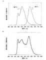
トルは、図1(B)に示す実線である。The light emitting layer formed by stacking the second light emitting layer 112-1 and the third light emitting layer 112-2 exhibits an emission spectrum having two peaks in the blue to green wavelength region. An emission spectrum obtained by sandwiching the light-emitting layer including this stack between a pair of electrodes (however, at least one of the electrodes has a light-transmitting property) is a solid line illustrated in FIG.
また、第1の発光層122は橙色〜赤色の波長領域にピークを有する発光スペクトルを示
す。この第1の発光層122を一対の電極(ただし、少なくとも一方は透光性を有する電
極)で挟んで得られる発光スペクトルは図1(B)に示す点線である。The first light-emitting
このように重ねた発光素子に対し、第1の陽極側をプラスに、第2の陰極側をマイナスに
バイアスを印加すると、ある電流密度Jの電流が素子に流れる。この時、第1の陽極12
1から第1の発光層122にホールが、第1の陰極123から第1の発光層122に電子
がそれぞれ注入され、再結合に至ることにより、第1の発光素子120から第1の発光が
得られる。なお、この第1の発光は、図1(B)に示す発光スペクトル140を有する。
また、第2の陽極111から第2の発光層112−1及び第3の発光層112−2にホー
ルが、第2の陰極113から第2の発光層112−1及び第3の発光層112−2に電子
がそれぞれ注入され、再結合に至ることにより、第2の発光素子110から第2の発光が
得られる。なお、この第2の発光は、図1(B)に示す発光スペクトル130を有する。
つまり、第1の発光素子120と第2の発光素子110の両方から発光が得られるわけで
ある。When a bias is applied to the stacked light emitting elements in such a manner that the first anode side is positive and the second cathode side is negative, a current having a current density J flows through the element. At this time, the
Holes are injected from 1 to the first light-emitting
In addition, holes are formed from the
That is, light emission can be obtained from both the first
なお、等価回路上では、第1の発光素子および第2の発光素子に共通の電流密度Jの電流
が流れ、それぞれその電流密度Jに対応した輝度で発光することになる。ここでは、第1
の陽極、及び第2の陽極を透光性の材料とすることにより、第1の発光と第2の発光の両
方を取り出すことができる。また、第2の陰極113は、光反射性を有する材料とするこ
とで発光を反射させて、光を取り出す面側に効率よく発光を得ることができる。Note that, on the equivalent circuit, a current having a current density J common to the first light emitting element and the second light emitting element flows, and light is emitted at a luminance corresponding to the current density J. Here, the first
By using a light-transmitting material for the anode and the second anode, both the first light emission and the second light emission can be extracted. In addition, the
ここで、本発明においては、第1の発光および第2の発光のうちいずれか一方は、少なく
とも2つのピークを有する第1の発光スペクトルを示し、他方はそれと異なる位置にピー
クを有する第2の発光スペクトルを示すことが特徴である。例えば、第1の発光が橙色〜
赤色の波長領域にピークを有する第1の発光スペクトルを示し、第2の発光が青色〜緑色
の波長領域に2つのピークを有する第2の発光スペクトルを示すような構成である。なお
、第1の発光と第2の発光は、どちらも白色光ではないが、補色の関係にあるため、両方
取り出された時には組み合わされて白色光となる。また、第2の陰極113は、光反射性
を有する材料であるため、光の干渉を考慮して、第2の発光層112−1、第3の発光層
112−2、第1の陽極121、及び第1の陰極123の膜厚を調節することが好ましい
。Here, in the present invention, either one of the first emission and the second emission shows the first emission spectrum having at least two peaks, and the other has the second emission having a peak at a different position. It is characterized by showing an emission spectrum. For example, the first emission is orange
The first emission spectrum having a peak in the red wavelength region is shown, and the second emission shows a second emission spectrum having two peaks in the blue to green wavelength region. Note that both the first light emission and the second light emission are not white light, but are in a complementary color relationship, so when both are extracted, they are combined into white light. In addition, since the
発光性の有機化合物が電流によって励起されて発光に至る発光素子では、2つのピークを
有する発光スペクトル(上述の例では第2の発光スペクトル)を示す発光を得るのは、従
来技術の2波長型白色発光素子に代表されるように比較的容易である。しかしながら、3
つ以上のピークを有する発光スペクトルを得る、あるいはブロードな発光スペクトルを得
るというのは非常に困難である。その技術的課題を克服する手法が、本発明の構成である
。すなわち、2波長型発光素子のような2つのピーク(青色〜緑色の波長領域に2つのピ
ーク)を有する発光スペクトルを示す発光素子(上述の例では第2の発光素子)をベース
に、それだけでは補完しきれない領域の発光スペクトルを有する発光素子を直列に積層し
、発光を重ね合わせて白色発光を得る構成である。この構成であれば、単に1つのピーク
しか有さない発光素子を直列に積層するよりは、積層する素子の数を減らすことができ、
それに伴って駆動電圧の上昇を抑えることができるため有用である。また、本発明の発光
素子においては、ある電流密度Jに対して得られる第1の発光素子の輝度と第2の発光素
子の輝度の両方を加算した輝度が得られるため、電流に対する輝度(すなわち電流効率)
も高い値が得られる。In a light-emitting element in which a light-emitting organic compound is excited by an electric current and emits light, light having a light emission spectrum having two peaks (the second light emission spectrum in the above example) is obtained by the conventional two-wavelength type. It is relatively easy as represented by white light emitting elements. However, 3
It is very difficult to obtain an emission spectrum having two or more peaks or a broad emission spectrum. A technique for overcoming the technical problem is the configuration of the present invention. That is, based on a light-emitting element (second light-emitting element in the above example) having an emission spectrum having two peaks (two peaks in the blue to green wavelength region) like a two-wavelength light-emitting element, In this configuration, light emitting elements having an emission spectrum in a region that cannot be complemented are stacked in series, and light emission is superimposed to obtain white light emission. With this configuration, it is possible to reduce the number of stacked elements rather than stacking light emitting elements having only one peak in series.
Along with this, it is useful because an increase in drive voltage can be suppressed. In the light-emitting element of the present invention, a luminance obtained by adding both the luminance of the first light-emitting element and the luminance of the second light-emitting element obtained with respect to a certain current density J is obtained. Current efficiency)
High values can be obtained.
また、図1(A)の説明では、第2の陰極113を光反射性材料とした例を示したが、第
2の陰極113を透光性材料とし、さらに第2の陰極の上方に反射材料膜を形成する構造
としてもよい。その場合、光の干渉を考慮して、第2の陰極113、第2の発光層112
−1、第3の発光層112−2、第1の陽極121、及び第1の陰極123の膜厚を調節
することが好ましい。反射材料膜は、電気抵抗の低い材料、例えばAl、Agなどを含む
導電材料を用いると、発光素子の低消費電力化が図れるため好ましい。In the description of FIG. 1A, an example in which the
−1, the third light emitting layer 112-2, the
また、上述の説明では、第2の陰極113を光反射性材料とし、第1の陽極及び基板10
0を通過させて発光を取り出す構成としているが、特にこの構造に限定されない。例えば
、基板上に第2の発光素子110を形成し、その上に第1の発光素子120を形成し、第
2の陽極111を光反射性材料とし、第2の陰極113、第1の陽極121、及び第1の
陰極123を透光性材料として、図1(A)に示す方向とは逆の方向に発光を取り出す構
造としてもよい。また、第2の陽極111を光反射性材料とするのではなく、第2の陽極
111を透光性材料とし、第2の陽極111の下方に反射性材料膜を設ける構造としても
よい。In the above description, the
Although the light emission is extracted by passing 0, it is not particularly limited to this structure. For example, the second light-emitting
上述したこれらの構造は、2つのピーク(青色〜緑色の波長領域に2つのピーク)を有す
る発光スペクトルを示す第2の発光素子を光反射性材料膜から近い距離に配置し、橙色〜
赤色の波長領域にピークを有する発光スペクトルを示す第1の発光素子を光反射性材料膜
から遠い距離に配置することで光の干渉を防ぐ構造とする。In these structures described above, the second light-emitting element exhibiting an emission spectrum having two peaks (two peaks in the blue to green wavelength region) is disposed at a short distance from the light-reflecting material film, and the orange to
The first light-emitting element having an emission spectrum having a peak in the red wavelength region is arranged at a distance far from the light-reflecting material film, thereby preventing light interference.
また、各積層の膜厚を調節し、意図的に光を僅かに干渉させることで、突出した鋭いピー
クの発生を抑え、連続的なスペクトルを有する自然光に近づけてもよい。また、各積層の
膜厚を調節し、意図的に光を僅かに干渉させることで、スペクトルのピークの位置も変化
させることもできる。In addition, by adjusting the film thickness of each stack and intentionally causing light to interfere slightly, the occurrence of protruding sharp peaks may be suppressed and the light may be brought closer to natural light having a continuous spectrum. Moreover, the position of the peak of a spectrum can also be changed by adjusting the film thickness of each lamination | stacking and intentionally making light interfere slightly.
本発明の発光素子においては、第2の発光素子の発光スペクトル130と第1の発光素子
の発光スペクトル140の両方を単に重ねたスペクトルを有する発光を得ることが目的で
はなく、発光素子の重ね方や、各積層の膜厚や、各積層の材料を調節し、光の干渉などに
よって、連続的なスペクトルを有する自然光に近い白色を得ることを特徴としている。In the light-emitting element of the present invention, the purpose is not to obtain light emission having a spectrum obtained by simply superimposing both the
以上では、第1の発光層、第2の発光層、及び第3の発光層に発光性の有機化合物を含む
場合を説明したが、発光層は発光性の無機化合物を含んでも良い。つまり第1の発光素子
と第2の発光素子を無機のLEDとする。そして、第1の発光および第2の発光のうちい
ずれか一方は、少なくとも2つのピーク(青色〜緑色の波長領域に2つのピーク)を有す
る第1の発光スペクトルを示し、他方はそれと異なる位置にピークを有する第2の発光ス
ペクトルを示すことを特徴とする。Although the case where the first light-emitting layer, the second light-emitting layer, and the third light-emitting layer include a light-emitting organic compound has been described above, the light-emitting layer may include a light-emitting inorganic compound. That is, the first light-emitting element and the second light-emitting element are inorganic LEDs. One of the first emission and the second emission shows a first emission spectrum having at least two peaks (two peaks in the blue to green wavelength region), and the other is at a different position. A second emission spectrum having a peak is shown.
また、電流によって発光に至る発光素子だけでなく、無機EL素子のような衝突励起型の
発光素子においても、本願の概念は適用できる。The concept of the present application can be applied not only to a light emitting element that emits light by current but also to a collision excitation type light emitting element such as an inorganic EL element.
すなわち、2つの衝突励起型の発光素子を直列に接続する。そして、2つの衝突励起型の
発光素子のうち一方は、少なくとも2つのピーク(青色〜緑色の波長領域に2つのピーク
)を有する第1の発光スペクトルを示し、他方はそれと異なる位置にピークを有する第2
の発光スペクトルを示すことを特徴とする。That is, two collision excitation type light emitting elements are connected in series. One of the two collisional excitation light-emitting elements shows a first emission spectrum having at least two peaks (two peaks in the blue to green wavelength region), and the other has a peak at a different position. Second
The emission spectrum is shown.
以上で述べたような構成とすることで、可視光領域の多くをカバーでき、高効率な白色光
を容易に得ることができる。By adopting the configuration as described above, it is possible to cover most of the visible light region and easily obtain highly efficient white light.
(実施の形態2)
図2(A)に素子構成を示した。図2(A)は、基板300上に第1の発光素子320と
第2の発光素子310が直列に積層された、本発明の発光素子の構成例である。第1の発
光素子320は、第1の陽極321と第1の陰極323の間に第1の発光層322−1及
び第2の発光層322−2を有する構造である。また、第2の発光素子310は、第2の
陽極311と第2の陰極313の間に第3の発光層312−1及び第4の発光層312−
2を有する構造である。(Embodiment 2)
The element structure is shown in FIG. FIG. 2A illustrates a structure example of the light-emitting element of the present invention in which a first light-emitting
2 is a structure having two.
ここで、第1の発光素子の発光層は、橙色〜赤色の波長領域にピークを有する発光スペク
トルを示す第1の発光層322−1と、青緑色〜緑色の波長領域にピークを有する発光ス
ペクトルを示す第2の発光層322−2とで構成されている。なお、第1の発光層322
−1と第2の発光層322−2は逆の積層順であっても良い。Here, the light emitting layer of the first light emitting element includes a first light emitting layer 322-1 showing an emission spectrum having a peak in an orange to red wavelength region, and an emission spectrum having a peak in a blue green to green wavelength region. And a second light emitting layer 322-2. Note that the first light-emitting layer 322
-1 and the second light emitting layer 322-2 may be in the reverse stacking order.
また、第2の発光素子の発光層は、黄色〜橙色の波長領域にピークを有する発光スペクト
ルを示す第3の発光層312−1と、青色〜青緑色の波長領域にピークを有する発光スペ
クトルを示す第4の発光層312−2とで構成されている。なお、第3の発光層312−
1と第4の発光層312−2は逆の積層順であっても良い。The light-emitting layer of the second light-emitting element has a third light-emitting layer 312-1 having an emission spectrum having a peak in the yellow to orange wavelength region and an emission spectrum having a peak in the blue to blue-green wavelength region. And the fourth light emitting layer 312-2 shown. Note that the third light emitting layer 312-
The first and fourth light emitting layers 312-2 may be stacked in reverse order.
このような発光素子に対し、第1の陽極321側をプラスに、第2の陰極313側をマイ
ナスにバイアスを印加すると、第1の発光と第2の発光を合成した発光が得られる。第1
の発光は、第1の発光層322−1および第2の発光層322−2の両方からの発光を合
わせたものであるので、図2(B)中の実線に示す通り、青緑色〜緑色の波長領域および
橙色〜赤色の波長領域の両方にピークを有する発光スペクトル330を示す。すなわち、
第1の発光素子は2波長型の白色または白色に近い色の発光を示すものである。When a bias is applied to such a light-emitting element with the
Since the light emission is a combination of light emission from both the first light-emitting layer 322-1 and the second light-emitting layer 322-2, blue-green to green as shown by a solid line in FIG. And an
The first light emitting element emits light of a two-wavelength type white color or a color close to white.
また、第2の発光は、第3の発光層312−1および第4の発光層312−2の両方から
の発光を合わせたものであるので、図2(B)中の点線に示す通り、青色〜青緑色の波長
領域および黄色〜橙色の波長領域の両方にピークを有する発光スペクトル340を示す。
すなわち、第2の発光素子は、第1の発光素子とは異なる2波長型の白色または白色に近
い色の発光を示すものである。In addition, since the second light emission is a combination of light emission from both the third light emitting layer 312-1 and the fourth light emitting layer 312-2, as shown by a dotted line in FIG. An
In other words, the second light-emitting element emits light of a two-wavelength type white color or a color close to white that is different from that of the first light-emitting element.
したがって、本実施の形態2における本発明の発光素子は、第1の発光素子の発光スペク
トル330および第2の発光素子の発光スペクトル340を重ね合せる結果、青色〜青緑
色の波長領域、青緑色〜緑色の波長領域、黄色〜橙色の波長領域、橙色〜赤色の波長領域
を幅広くカバーする白色発光が得られる。Therefore, the light-emitting element of the present invention in
また、第2の陰極313を光反射性材料とし、第1の陽極321及び基板300を通過さ
せて発光を取り出す構成としてもよい。この場合は、橙色〜赤色の波長領域にピークを有
する発光スペクトルを示す第1の発光素子を光反射性材料膜から遠い距離に配置すること
で光の干渉を防ぐ構造とする。また、第2の陰極313を光反射性材料とするのではなく
、第2の陰極313を透光性材料とし、第2の陰極313の上方に反射性材料膜を設ける
構造としてもよい。Alternatively, the
さらに、各積層の膜厚を調節し、意図的に光を僅かに干渉させることで、突出した鋭いピ
ークの発生を抑え、台形の発光スペクトルとなるようにして、連続的なスペクトルを有す
る自然光に近づけてもよい。また、各積層の膜厚を調節し、意図的に光を僅かに干渉させ
ることで、発光スペクトルのピークの位置も変化させることもできる。発光スペクトルに
現れる複数のピーク強度をほぼ同じになるように各積層の膜厚を調節し、さらに、互いの
ピークの間隔を狭くすることによってより台形に近い発光スペクトルを有する白色発光を
得ることができる。Furthermore, by adjusting the film thickness of each stack and intentionally causing light to interfere slightly, the occurrence of protruding sharp peaks is suppressed, and a trapezoidal emission spectrum is obtained, resulting in natural light having a continuous spectrum. It may be close. Moreover, the peak position of the emission spectrum can also be changed by adjusting the film thickness of each layer and intentionally causing slight interference of light. It is possible to obtain white light emission having a more trapezoidal emission spectrum by adjusting the film thickness of each stack so that the plurality of peak intensities appearing in the emission spectrum are substantially the same, and further reducing the interval between the peaks. it can.
また、例えば、第4の発光層312−2(青色〜青緑色の波長領域にピークを有する発光
スペクトルを示す)の発光輝度が、経時劣化あるいは電流密度により変化したとしても、
スペクトル全体に対する第4の発光層312−2の寄与は1/4程度であるため、色度の
ずれは比較的小さくて済むという利点もある。もし従来の2波長型白色発光素子であれば
、発光層の輝度変化は色度に大きな影響を及ぼしてしまう。Further, for example, even if the emission luminance of the fourth light emitting layer 312-2 (showing an emission spectrum having a peak in the blue to blue-green wavelength region) changes due to deterioration over time or current density,
Since the contribution of the fourth light-emitting layer 312-2 to the entire spectrum is about 1/4, there is an advantage that the chromaticity shift is relatively small. If it is a conventional two-wavelength type white light emitting element, the luminance change of the light emitting layer has a great influence on the chromaticity.
また、基板上に第2の発光素子310を形成し、その上に第1の発光素子320を形成し
、第2の陽極311を光反射性材料とし、第2の陰極313、第1の陽極321、及び第
1の陰極323を透光性材料として、図2(A)に示す方向とは逆の方向に発光を取り出
す構造としてもよい。また、第2の陽極311を光反射性材料とするのではなく、第2の
陽極311を透光性材料とし、第2の陽極311の下方に反射性材料膜を設ける構造とし
てもよい。In addition, the second light-emitting
(実施の形態3)
次に、以下では、本発明の発光素子の構成、図1(A)における第1の発光素子120と
第2の発光素子110、または図2(A)における第1の発光素子320と第2の発光素
子310に関し、用いることのできる材料や素子構造を説明する。図1(A)において、
第2の陽極111と第2の発光層112−1との間、および第1の陽極121と第1の発
光層122との間には、ホール注入層および/またはホール輸送層を挿入していても良い
。また、図1(A)において、第2の陰極113と第3の発光層112−2との間、およ
び第1の陰極123と第1の発光層122との間には、電子注入層および/または電子輸
送層を挿入していても良い。図2(A)において、第2の陽極311と第3の発光層31
2−1との間、および第1の陽極321と第1の発光層322−1との間には、ホール注
入層および/またはホール輸送層を挿入していても良い。また、図2(A)において、第
2の陰極313と第4の発光層312−2との間、および第1の陰極323と第2の発光
層322−2との間には、電子注入層および/または電子輸送層を挿入していても良い。(Embodiment 3)
Next, the structure of the light-emitting element of the present invention, the first light-emitting
A hole injection layer and / or a hole transport layer is inserted between the
A hole injection layer and / or a hole transport layer may be inserted between the 2-1 and between the
なお、ホール注入層は陽極からホールを受け取る機能を示す層であり、ホール輸送層は発
光層にホールを受け渡す機能を示す層である。また、電子注入層は陰極から電子を受け取
る機能を示す層であり、電子輸送層は発光層に電子を受け渡す機能を示す層である。The hole injection layer is a layer showing a function of receiving holes from the anode, and the hole transport layer is a layer showing a function of delivering holes to the light emitting layer. The electron injection layer is a layer that has a function of receiving electrons from the cathode, and the electron transport layer is a layer that has a function of transferring electrons to the light emitting layer.
まず、それら各層に用いることのできる材料を具体的に例示する。ただし、本発明に適用
できる材料は、これらに限定されるものではない。First, materials that can be used for each of these layers are specifically exemplified. However, materials applicable to the present invention are not limited to these.
ホール注入層に用いることができるホール注入材料としては、フタロシアニン系の化合
物が有効であり、フタロシアニン(略称:H2Pc)、銅フタロシアニン(略称:CuP
c)、バナジルフタロシアニン(略称:VOPc)等を用いることができる。また、導電
性高分子化合物に化学ドーピングを施した材料もあり、ポリスチレンスルホン酸(略称:
PSS)をドープしたポリエチレンジオキシチオフェン(略称:PEDOT)やポリアニ
リン(略称:PAni)などを用いることもできる。また、酸化モリブデン、酸化バナジ
ウム、酸化ニッケルなどの無機半導体の薄膜や、酸化アルミニウムなどの無機絶縁体の超
薄膜も有効である。また、4,4’,4’’−トリス(N,N−ジフェニル−アミノ)−
トリフェニルアミン(略称:TDATA)、4,4’,4’’−トリス[N−(3−メチ
ルフェニル)−N−フェニル−アミノ]−トリフェニルアミン(略称:MTDATA)、
N,N’−ビス(3−メチルフェニル)−N,N’−ジフェニル−1,1’−ビフェニル
−4,4’−ジアミン(略称:TPD)、4,4’−ビス[N−(1−ナフチル)−N−
フェニルアミノ]ビフェニル(略称:NPB)、N,N’−ビス[4−[ビス(3−メチ
ルフェニル)アミノ]フェニル]−N,N’−ジフェニル−[1,1’−ビフェニル]−
4,4’−ジアミン(略称:DNTPD)などの芳香族アミン系化合物も用いることがで
きる。さらに、それら芳香族アミン系化合物に対してアクセプタ性を示す物質を芳香族ア
ミン系化合物に添加してもよく、具体的にはVOPcにアクセプタである7,7,8,8
−テトラシアノ−2,3,5,6−テトラフルオロキノジメタン(略称:F4−TCNQ
)を添加したものや、NPBにアクセプタである酸化モリブデンを添加したものを用いて
もよい。As a hole injection material that can be used for the hole injection layer, a phthalocyanine-based compound is effective, and phthalocyanine (abbreviation: H2 Pc), copper phthalocyanine (abbreviation: CuP).
c), vanadyl phthalocyanine (abbreviation: VOPc), and the like can be used. There is also a material obtained by chemically doping a conductive polymer compound, such as polystyrene sulfonic acid (abbreviation:
Polyethylenedioxythiophene (abbreviation: PEDOT) doped with PSS) or polyaniline (abbreviation: PAni) can also be used. In addition, an inorganic semiconductor thin film such as molybdenum oxide, vanadium oxide, or nickel oxide, or an ultrathin film of an inorganic insulator such as aluminum oxide is also effective. Also, 4,4 ′, 4 ″ -tris (N, N-diphenyl-amino)-
Triphenylamine (abbreviation: TDATA), 4,4 ′, 4 ″ -tris [N- (3-methylphenyl) -N-phenyl-amino] -triphenylamine (abbreviation: MTDATA),
N, N′-bis (3-methylphenyl) -N, N′-diphenyl-1,1′-biphenyl-4,4′-diamine (abbreviation: TPD), 4,4′-bis [N- (1 -Naphthyl) -N-
Phenylamino] biphenyl (abbreviation: NPB), N, N′-bis [4- [bis (3-methylphenyl) amino] phenyl] -N, N′-diphenyl- [1,1′-biphenyl]-
Aromatic amine compounds such as 4,4′-diamine (abbreviation: DNTPD) can also be used. Furthermore, a substance showing acceptability with respect to these aromatic amine compounds may be added to the aromatic amine compound, specifically, 7, 7, 8, 8 which is an acceptor for VOPc.
- tetracyano-2,3,5,6-tetrafluoro quinodimethane(abbreviation: F 4 -TCNQ
) Or in which NPB is added with molybdenum oxide as an acceptor may be used.
ホール輸送層に用いることができるホール輸送材料としては、芳香族アミン系化合物が
好適であり、上述したTDATA、MTDATA、TPD、NPB、DNTPDなどを用
いることができる。As a hole transport material that can be used for the hole transport layer, an aromatic amine compound is suitable, and the above-described TDATA, MTDATA, TPD, NPB, DNTPD, and the like can be used.
電子輸送層に用いることができる電子輸送材料としては、トリス(8−キノリノラト)
アルミニウム(略称:Alq3)、トリス(4−メチル−8−キノリノラト)アルミニウ
ム(略称:Almq3)、ビス(10−ヒドロキシベンゾ[h]−キノリナト)ベリリウ
ム(略称:BeBq2)、ビス(2−メチル−8−キノリノラト)(4−フェニルフェノ
ラト)アルミニウム(略称:BAlq)、ビス[2−(2−ヒドロキシフェニル)ベンゾ
オキサゾラト]亜鉛(略称:Zn(BOX)2)、ビス[2−(2−ヒドロキシフェニル
)ベンゾチアゾラト]亜鉛(略称:Zn(BTZ)2)などの金属錯体が挙げられる。さ
らに、金属錯体以外にも、2−(4−ビフェニリル)−5−(4−tert−ブチルフェ
ニル)−1,3,4−オキサジアゾール(略称:PBD)、1,3−ビス[5−(p−t
ert−ブチルフェニル)−1,3,4−オキサジアゾール−2−イル]ベンゼン(略称
:OXD−7)などのオキサジアゾール誘導体、3−(4’−tert−ブチルフェニル
)−4−フェニル−5−(4”−ビフェニル)−1,2,4−トリアゾール(略称:TA
Z)、3−(4−tert−ブチルフェニル)−4−(4−エチルフェニル)−5−(4
−ビフェニリル)−1,2,4−トリアゾール(略称:p−EtTAZ)などのトリアゾ
ール誘導体、2,2’,2”−(1,3,5−ベンゼントリイル)トリス[1−フェニル
−1H−ベンゾイミダゾール](略称:TPBI)のようなイミダゾール誘導体、バソフ
ェナントロリン(略称:BPhen)、バソキュプロイン(略称:BCP)などのフェナ
ントロリン誘導体を用いることができる。As an electron transport material that can be used for the electron transport layer, Tris (8-quinolinolato) is used.
Aluminum (abbreviation: Alq3 ), tris (4-methyl-8-quinolinolato) aluminum (abbreviation: Almq3 ), bis (10-hydroxybenzo [h] -quinolinato) beryllium (abbreviation: BeBq2 ), bis (2- Methyl-8-quinolinolato) (4-phenylphenolato) aluminum (abbreviation: BAlq), bis [2- (2-hydroxyphenyl) benzoxazolate] zinc (abbreviation: Zn (BOX)2 ), bis [2- And metal complexes such as (2-hydroxyphenyl) benzothiazolate] zinc (abbreviation: Zn (BTZ)2 ). In addition to metal complexes, 2- (4-biphenylyl) -5- (4-tert-butylphenyl) -1,3,4-oxadiazole (abbreviation: PBD), 1,3-bis [5- (Pt
ert-butylphenyl) -1,3,4-oxadiazol-2-yl] benzene (abbreviation: OXD-7) and other oxadiazole derivatives, 3- (4′-tert-butylphenyl) -4-phenyl -5- (4 "-biphenyl) -1,2,4-triazole (abbreviation: TA)
Z), 3- (4-tert-butylphenyl) -4- (4-ethylphenyl) -5- (4
-Biphenylyl) -1,2,4-triazole (abbreviation: p-EtTAZ) and other triazole derivatives, 2,2 ′, 2 ″-(1,3,5-benzenetriyl) tris [1-phenyl-1H— An imidazole derivative such as benzimidazole (abbreviation: TPBI), a phenanthroline derivative such as bathophenanthroline (abbreviation: BPhen), and bathocuproin (abbreviation: BCP) can be used.
電子注入層に用いることができる電子注入材料としては、上述したAlq3、Almq3
、BeBq2、BAlq、Zn(BOX)2、Zn(BTZ)2、PBD、OXD−7、
TAZ、p−EtTAZ、TPBI、BPhen、BCPなどの電子輸送材料を用いるこ
とができる。その他に、LiF、CsFなどのアルカリ金属ハロゲン化物や、CaF2の
ようなアルカリ土類ハロゲン化物、Li2Oなどのアルカリ金属酸化物のような絶縁体の
超薄膜がよく用いられる。また、リチウムアセチルアセトネート(略称:Li(acac
))や8−キノリノラトリチウム(略称:Liq)などのアルカリ金属錯体も有効である
。また、これら電子注入材料に対してドナー性を示す物質を電子注入材料に添加してもよ
く、ドナーとしてはアルカリ金属、アルカリ土類金属、希土類金属などを用いることがで
きる。具体的にはBCPにドナーであるリチウムを添加したものや、Alq3にドナーで
あるリチウムを添加したものを用いることができる。Examples of the electron injection material that can be used for the electron injection layer include Alq3 and Almq3 described above.
, BeBq2 , BAlq, Zn (BOX)2 , Zn (BTZ)2 , PBD, OXD-7,
Electron transport materials such as TAZ, p-EtTAZ, TPBI, BPhen, and BCP can be used. In addition, an ultra-thin film of an insulator such as an alkali metal halide such as LiF or CsF, an alkaline earth halide such as CaF2 , or an alkali metal oxide such as Li2 O is often used. In addition, lithium acetylacetonate (abbreviation: Li (acac
And alkali metal complexes such as 8-quinolinolato lithium (abbreviation: Liq) are also effective. Further, a substance exhibiting a donor property with respect to these electron injection materials may be added to the electron injection material, and alkali metals, alkaline earth metals, rare earth metals, and the like can be used as donors. Specifically, a material obtained by adding lithium as a donor to BCP or a material obtained by adding lithium as a donor to Alq3 can be used.
次に、図1(A)における第1の発光素子120や第2の発光素子110における発光
層(122、112−1、112−2)の構成や、図2(A)における第1の発光素子3
20や第2の発光素子310における発光層(322−1、322−2、312−1、3
12−2)の構成を説明する。まず、発光性の有機化合物として用いることのできる材料
を列挙するが、本発明においてはこれらに限定されず、いかなる発光性の有機化合物を用
いても良い。Next, the structure of the light-emitting layers (122, 112-1, and 112-2) in the first light-emitting
20 and the light emitting layer (322-1, 322-2, 312-1, 3 in the second light emitting element 310).
The configuration of 12-2) will be described. First, materials that can be used as the light-emitting organic compound are listed, but the present invention is not limited to these, and any light-emitting organic compound may be used.
例えば青色〜青緑色の発光は、ペリレン、2,5,8,11−テトラ−t−ブチルペリ
レン(略称:TBP)、9,10−ジフェニルアントラセンなどをゲスト材料として用い
、適当なホスト材料に分散させることによって得られる。また、4,4’−ビス(2,2
−ジフェニルビニル)ビフェニル(略称:DPVBi)などのスチリルアリーレン誘導体
や、9,10−ジ(2−ナフチル)アントラセン(略称:DNA)、9,10−ビス(2
−ナフチル)−2−t−ブチルアントラセン(略称:t−BuDNA)などのアントラセ
ン誘導体から得ることができる。また、ポリ(9,9−ジオクチルフルオレン)等のポリ
マーを用いても良い。また、青色発光のゲスト材料としては、スチリルアミン誘導体が好
ましく、N,N’−ビス[4−(9H−カルバゾール−9−イル)フェニル]−N,N’
−ジフェニルスチルベン−4,4’−ジアミン(略称:YGA2S)や、N,N’−ジフ
ェニル−N,N’−ビス(9−フェニル−9H−カルバゾール−3−イル)スチルベン−
4,4’−ジアミン(略称:PCA2S)などが挙げられる。特にYGA2Sは、450
nm付近にピークを有しており好ましい。また、ホスト材料としては、アントラセン誘導
体が好ましく、9,10−ビス(2−ナフチル)−2−t−ブチルアントラセン(略称:
t−BuDNA)や、9−[4−(10−フェニル−9−アントリル)フェニル]−9H
−カルバゾール(略称:CzPA)が好適である。特に、CzPAは電気化学的に安定で
あるため好ましい。For example, blue to blue-green light emission is dispersed in a suitable host material using perylene, 2,5,8,11-tetra-t-butylperylene (abbreviation: TBP), 9,10-diphenylanthracene, etc. as a guest material. To obtain. In addition, 4,4′-bis (2,2
-Styrylarylene derivatives such as -diphenylvinyl) biphenyl (abbreviation: DPVBi), 9,10-di (2-naphthyl) anthracene (abbreviation: DNA), 9,10-bis (2
-Naphthyl) -2-t-butylanthracene (abbreviation: t-BuDNA) and other anthracene derivatives. A polymer such as poly (9,9-dioctylfluorene) may also be used. In addition, as a guest material that emits blue light, a styrylamine derivative is preferable, and N, N′-bis [4- (9H-carbazol-9-yl) phenyl] -N, N ′ is used.
-Diphenylstilbene-4,4'-diamine (abbreviation: YGA2S) and N, N'-diphenyl-N, N'-bis (9-phenyl-9H-carbazol-3-yl) stilbene-
4,4′-diamine (abbreviation: PCA2S) and the like can be given. Especially YGA2S is 450
It has a peak in the vicinity of nm, which is preferable. As a host material, an anthracene derivative is preferable, and 9,10-bis (2-naphthyl) -2-t-butylanthracene (abbreviation:
t-BuDNA) and 9- [4- (10-phenyl-9-anthryl) phenyl] -9H
-Carbazole (abbreviation: CzPA) is preferred. In particular, CzPA is preferable because it is electrochemically stable.
例えば青緑色〜緑色の発光は、クマリン30、クマリン6などのクマリン系色素や、ビ
ス[2−(4’,6’−ジフルオロフェニル)ピリジナト−N,C2’]イリジウム(I
II)ピコリナート(略称:FIrpic)、ビス(2−フェニルピリジナト)イリジウ
ム(III)アセチルアセトナート(Ir(ppy)2(acac))などをゲスト材料
として用い、適当なホスト材料に分散させることによって得られる。また、上述のペリレ
ンやTBPを5wt%以上の高濃度で適当なホスト材料に分散させることによっても得ら
れる。また、BAlq、Zn(BTZ)2、ビス(2−メチル−8−キノリノラト)ガリ
ウム(III)クロリド(Ga(mq)2Cl)などの金属錯体からも得ることができる
。また、ポリ(p−フェニレンビニレン)等のポリマーを用いても良い。また、青緑色〜
緑色の発光層のゲスト材料としては、アントラセン誘導体が効率の高い発光が得られるた
め好ましい。例えば、9,10−ビス{4−[N−(4−ジフェニルアミノ)フェニル−
N−フェニル]アミノフェニル}−2−tert−ブチルアントラセン(略称:DPAB
PA)を用いることにより、高効率な青緑色発光が得られる。また、2位にアミノ基が置
換されたアントラセン誘導体は高効率な緑色発光が得られるため好ましく、N−(9,1
0−ジフェニル−2−アントリル)−N,9−ジフェニル−9H−カルバゾール−3−ア
ミン(略称:2PCAPA)が特に長寿命であり好適である。これらのホスト材料として
はアントラセン誘導体が好ましく、先に述べたCzPAが電気化学的に安定であるため好
ましい。また、緑色発光と青色発光を組み合わせ、青色から緑色の波長領域に2つのピー
クを持つ発光素子を作製する場合(例えば、前述した実施の形態1に示す第2の発光素子
を作製する場合)、青色発光層のホストにCzPAのような電子輸送性のアントラセン誘
導体を用い、緑色発光層のホストにNPBのようなホール輸送性の芳香族アミン化合物を
用いると、青色発光層と緑色発光層との界面で発光が得られるため好ましい。すなわちこ
の場合、2PCAPAのような緑色発光材料のホストとしては、NPBの如き芳香族アミ
ン化合物が好ましい。For example, blue-green to green light is emitted from coumarin dyes such as coumarin 30 and
II) Using picolinate (abbreviation: FIrpic), bis (2-phenylpyridinato) iridium (III) acetylacetonate (Ir (ppy)2 (acac)), etc. as a guest material and dispersing it in a suitable host material Obtained by. It can also be obtained by dispersing the above-described perylene or TBP in a suitable host material at a high concentration of 5 wt% or more. It can also be obtained from metal complexes such as BAlq, Zn (BTZ)2 , bis (2-methyl-8-quinolinolato) gallium (III) chloride (Ga (mq)2 Cl). A polymer such as poly (p-phenylene vinylene) may also be used. Also, blue-green ~
As the guest material for the green light-emitting layer, an anthracene derivative is preferable because highly efficient light emission can be obtained. For example, 9,10-bis {4- [N- (4-diphenylamino) phenyl-
N-phenyl] aminophenyl} -2-tert-butylanthracene (abbreviation: DPAB)
By using (PA), highly efficient blue-green light emission can be obtained. An anthracene derivative having an amino group substituted at the 2-position is preferable because highly efficient green light emission is obtained, and N- (9,1
0-diphenyl-2-anthryl) -N, 9-diphenyl-9H-carbazol-3-amine (abbreviation: 2PCAPA) is particularly preferable because of its long life. As these host materials, anthracene derivatives are preferable, and CzPA described above is preferable because it is electrochemically stable. Further, when green light emission and blue light emission are combined to produce a light-emitting element having two peaks in the blue to green wavelength region (for example, when the second light-emitting element shown in the first embodiment described above is produced), When an electron transporting anthracene derivative such as CzPA is used for the host of the blue light emitting layer and a hole transporting aromatic amine compound such as NPB is used for the host of the green light emitting layer, the blue light emitting layer and the green light emitting layer It is preferable because light emission can be obtained at the interface. That is, in this case, an aromatic amine compound such as NPB is preferable as the host of the green light emitting material such as 2PCAPA.
例えば黄色〜橙色の発光は、ルブレン、4−(ジシアノメチレン)−2,6−ビス[2
−(ジュロリジン−9−イル)エテニル]−4H−ピラン(略称:BisDCJ)、4−
(ジシアノメチレン)−2−メチル−6−(9−ジュロリジル)エチニル−4H−ピラン
(略称:DCM2)、ビス[2−(2−チエニル)ピリジナト]アセチルアセトナトイリ
ジウム(Ir(thp)2(acac))、ビス(2−フェニルキノリナト)イリジウム
(III)アセチルアセトナート(Ir(pq)2(acac))などをゲスト材料とし
て用い、適当なホスト材料に分散させることによって得られる。特に、ゲスト材料として
ルブレンのようなテトラセン誘導体が、高効率かつ化学的に安定であるため好ましい。こ
の場合のホスト材料としては、NPBのような芳香族アミン化合物が好ましい。他のホス
ト材料としては、ビス(8−キノリノラト)亜鉛(略称:Znq2)やビス[2−シンナ
モイル−8−キノリノラト]亜鉛(略称:Znsq2)などの金属錯体を用いることがで
きる。また、ポリ(2,5−ジアルコキシ−1,4−フェニレンビニレン)等のポリマー
を用いても良い。For example, yellow to orange light emission is obtained by rubrene, 4- (dicyanomethylene) -2,6-bis [2
-(Julolidin-9-yl) ethenyl] -4H-pyran (abbreviation: BisDCJ), 4-
(Dicyanomethylene) -2-methyl-6- (9-julolidyl) ethynyl-4H-pyran (abbreviation: DCM2), bis [2- (2-thienyl) pyridinato] acetylacetonatoiridium (Ir (thp)2 (acac )), Bis (2-phenylquinolinato) iridium (III) acetylacetonate (Ir (pq)2 (acac)) or the like as a guest material and dispersed in a suitable host material. In particular, a tetracene derivative such as rubrene is preferable as a guest material because it is highly efficient and chemically stable. In this case, the host material is preferably an aromatic amine compound such as NPB. As another host material, a metal complex such as bis (8-quinolinolato) zinc (abbreviation: Znq2 ) or bis [2-cinnamoyl-8-quinolinolato] zinc (abbreviation: Znsq2 ) can be used. Further, a polymer such as poly (2,5-dialkoxy-1,4-phenylene vinylene) may be used.
例えば橙色〜赤色の発光は、4−(ジシアノメチレン)−2,6−ビス[p−(ジメチ
ルアミノ)スチリル]−4H−ピラン(略称:BisDCM)、4−(ジシアノメチレン
)−2,6−ビス[2−(ジュロリジン−9−イル)エテニル]−4H−ピラン(略称:
BisDCJ)、4−(ジシアノメチレン)−2−メチル−6−(9−ジュロリジル)エ
チニル−4H−ピラン(略称:DCM2)、ビス[2−(2−チエニル)ピリジナト]ア
セチルアセトナトイリジウム(Ir(thp)2(acac))、などをゲスト材料とし
て用い、適当なホスト材料に分散させることによって得られる。ビス(8−キノリノラト
)亜鉛(略称:Znq2)やビス[2−シンナモイル−8−キノリノラト]亜鉛(略称:
Znsq2)などの金属錯体からも得ることができる。また、ポリ(3−アルキルチオフ
ェン)等のポリマーを用いても良い。赤色発光を示すゲスト材料としては、4−(ジシア
ノメチレン)−2,6−ビス[p−(ジメチルアミノ)スチリル]−4H−ピラン(略称
:BisDCM)、4−(ジシアノメチレン)−2,6−ビス[2−(ジュロリジン−9
−イル)エテニル]−4H−ピラン(略称:BisDCJ)、4−(ジシアノメチレン)
−2−メチル−6−(9−ジュロリジル)エチニル−4H−ピラン(略称:DCM2)、
{2−イソプロピル−6−[2−(2,3,6,7−テトラヒドロ−1,1,7,7−テ
トラメチル−1H,5H−ベンゾ[ij]キノリジン−9−イル)エテニル]−4H−ピ
ラン−4−イリデン}プロパンジニトリル(略称:DCJTI)、{2,6−ビス[2−
(2,3,6,7−テトラヒドロ−8−メトキシ−1,1,7,7−テトラメチル−1H
,5H−ベンゾ[ij]キノリジン−9−イル)エテニル]−4H−ピラン−4−イリデ
ン}プロパンジニトリル(略称:BisDCJTM)のような4H−ピラン誘導体が高効
率であり、好ましい。特に、DCJTI、BisDCJTMは、620nm付近に発光ピ
ークを有するため好ましい。なお、ホスト材料に関しては、前述した実施の形態1のよう
に赤色発光を示す第1の発光素子を作製する場合、Alq3のような金属錯体と、ルブレ
ンのようなテトラセン誘導体とを混合したホスト材料を用いることが好ましい。また、前
述した実施の形態2のように、赤色発光と青緑色発光を組み合わせた発光素子を作製する
場合、ホスト材料はNPBのような芳香族アミン化合物が好ましい。For example, light emission of orange to red is caused by 4- (dicyanomethylene) -2,6-bis [p- (dimethylamino) styryl] -4H-pyran (abbreviation: BisDCM), 4- (dicyanomethylene) -2,6- Bis [2- (julolidin-9-yl) ethenyl] -4H-pyran (abbreviation:
BisDCJ), 4- (dicyanomethylene) -2-methyl-6- (9-julolidyl) ethynyl-4H-pyran (abbreviation: DCM2), bis [2- (2-thienyl) pyridinato] acetylacetonatoiridium (Ir ( thp)2 (acac)), etc. are used as guest materials and dispersed in a suitable host material. Bis (8-quinolinolato) zinc (abbreviation: Znq2 ) or bis [2-cinnamoyl-8-quinolinolato] zinc (abbreviation:
It can also be obtained from a metal complex such as Znsq2 ). A polymer such as poly (3-alkylthiophene) may also be used. As guest materials that exhibit red light emission, 4- (dicyanomethylene) -2,6-bis [p- (dimethylamino) styryl] -4H-pyran (abbreviation: BisDCM), 4- (dicyanomethylene) -2,6 -Bis [2- (julolidine-9
-Yl) ethenyl] -4H-pyran (abbreviation: BisDCJ), 4- (dicyanomethylene)
2-methyl-6- (9-julolidyl) ethynyl-4H-pyran (abbreviation: DCM2),
{2-Isopropyl-6- [2- (2,3,6,7-tetrahydro-1,1,7,7-tetramethyl-1H, 5H-benzo [ij] quinolizin-9-yl) ethenyl] -4H -Pyran-4-ylidene} propanedinitrile (abbreviation: DCJTI), {2,6-bis [2-
(2,3,6,7-tetrahydro-8-methoxy-1,1,7,7-tetramethyl-1H
, 5H-benzo [ij] quinolizin-9-yl) ethenyl] -4H-pyran-4-ylidene} propanedinitrile (abbreviation: BisDCJTM) is preferred because of its high efficiency. In particular, DCJTI and BisDCJTM are preferable because they have an emission peak near 620 nm. As for the host material, when the first light-emitting element that emits red light as in
なお、上記の構成において、適当なホスト材料としては、発光性の有機化合物よりも発
光色が短波長のものであるか、またはエネルギーギャップの大きいものであればよい。具
体的には、上述した例に代表されるホール輸送材料や電子輸送材料から適宜選択すること
ができる。また、4,4’−ビス(N−カルバゾリル)ビフェニル(略称:CBP)、4
,4’,4’’−トリス(N−カルバゾリル)トリフェニルアミン(略称:TCTA)、
1,3,5−トリス[4−(N−カルバゾリル)フェニル]ベンゼン(略称:TCPB)
などを使用しても良い。Note that in the above structure, a suitable host material may be any material that emits light with a shorter wavelength or has a larger energy gap than the light-emitting organic compound. Specifically, it can be appropriately selected from hole transport materials and electron transport materials represented by the examples described above. In addition, 4,4′-bis (N-carbazolyl) biphenyl (abbreviation: CBP), 4
, 4 ′, 4 ″ -tris (N-carbazolyl) triphenylamine (abbreviation: TCTA),
1,3,5-tris [4- (N-carbazolyl) phenyl] benzene (abbreviation: TCPB)
Etc. may be used.
また、本発明の発光素子における陽極(第2の陽極111、311および第1の陽極12
1、321)材料としては、仕事関数の大きい導電性材料を用いることが好ましい。また
、第2の陽極111、311から光を取り出す場合は、第2の陽極111、311はイン
ジウムスズ酸化物(ITO)、インジウム亜鉛酸化物(IZO)、酸化亜鉛(ZnO)、
酸化ケイ素を添加したインジウム錫酸化物等の透明導電性材料を用いればよい。また、第
2の陽極111、311側を遮光性とするのであれば、第2の陽極111、311は窒化
チタン、窒化ジルコニウム、チタン、タングステン、ニッケル、Pt、クロム等の単層膜
の他、窒化チタン膜とアルミニウムを主成分とする膜との積層、窒化チタン膜とアルミニ
ウムを主成分とする膜と窒化チタン膜との三層構造等を用いることができる。あるいは、
チタン、アルミニウム等の反射性電極の上に上述した透明導電性材料を積層する方法でも
よい。また、第1の陽極121、321は光透過性が必要であり、ITO、IZO、Zn
Oなどの透明導電性材料の他、上述したホール輸送性の化合物(特に芳香族アミン系化合
物)に対してアクセプタ性を示す物質をホール輸送性の化合物に添加した構成を用いても
良い。具体的にはVOPcにアクセプタである7,7,8,8−テトラシアノ−2,3,
5,6−テトラフルオロキノジメタン(略称:F4−TCNQ)を添加したものや、NP
Bにアクセプタである酸化モリブデンを添加したものを第1の陽極121、321として
用いてもよい。Further, the anodes (
1,321) As a material, it is preferable to use a conductive material having a high work function. When light is extracted from the
A transparent conductive material such as indium tin oxide to which silicon oxide is added may be used. If the
A method of laminating the above-described transparent conductive material on a reflective electrode such as titanium or aluminum may also be used. In addition, the
In addition to a transparent conductive material such as O, a structure in which a substance exhibiting acceptor properties with respect to the above-described hole transporting compound (particularly, an aromatic amine compound) is added to the hole transporting compound may be used. Specifically, 7,7,8,8-tetracyano-2,3, which is an acceptor for VOPc.
5,6-tetrafluoroquinodimethane (abbreviation: F4 -TCNQ) added or NP
A material obtained by adding molybdenum oxide as an acceptor to B may be used as the
また、陰極(第2の陰極113、313および第1の陰極123、323)材料としては
、仕事関数の小さい導電性材料を用いることが好ましく、具体的には、LiやCs等のア
ルカリ金属、およびMg、Ca、Sr等のアルカリ土類金属、およびこれらを含む合金(
Mg:Ag、Al:Liなど)の他、YbやEr等の希土類金属を用いて形成することも
できる。また、LiF、CsF、CaF2、Li2O等の電子注入層を用いる場合は、ア
ルミニウム等の通常の導電性薄膜を用いることができる。また、第1の陰極123、32
3側を光の取り出し方向とする場合は、LiやCs等のアルカリ金属、およびMg、Ca
、Sr等のアルカリ土類金属を含む超薄膜と、透明導電膜(ITO、IZO、ZnO等)
との積層構造を用いればよい。あるいは、上述した電子輸送材料に対してドナー性を示す
物質(アルカリ金属またはアルカリ土類金属など)を電子輸送材料に添加した構成を用い
、その上に透明導電膜(ITO、IZO、ZnO等)を積層してもよい。また、第1の陰
極123、323は光透過性が必要であり、上述した電子輸送材料に対してドナー性を示
す物質(アルカリ金属またはアルカリ土類金属など)を電子輸送材料に添加した構成を用
いても良い。具体的にはBPhenにドナーであるリチウムを添加したものや、Alq3
にドナーであるリチウムを添加したものを用いることができる。In addition, as a material for the cathode (
In addition to (Mg: Ag, Al: Li, etc.), a rare earth metal such as Yb or Er can also be used. Further, LiF, CsF, in the case of using an electron injecting layer such asCaF2, Li 2 O, may be used usual conductive thin film such as aluminum. Also, the
When the third side is the light extraction direction, alkali metals such as Li and Cs, and Mg and Ca
, Ultrathin films containing alkaline earth metals such as Sr, and transparent conductive films (ITO, IZO, ZnO, etc.)
A stacked structure may be used. Alternatively, a structure in which a substance exhibiting donor properties (such as an alkali metal or an alkaline earth metal) added to the electron transport material described above is added to the electron transport material, and a transparent conductive film (ITO, IZO, ZnO, or the like) is formed thereon. May be laminated. The
A material obtained by adding lithium as a donor to can be used.
なお、以上で述べた本発明の発光素子を作製するに当たっては、発光素子中の各層の積層
法を限定されるものではない。積層が可能ならば、真空蒸着法やスピンコート法、インク
ジェット法、ディップコート法など、どの様な手法を選んでも良いものとする。Note that in manufacturing the light-emitting element of the present invention described above, the stacking method of each layer in the light-emitting element is not limited. As long as lamination is possible, any method such as a vacuum deposition method, a spin coating method, an ink jet method, or a dip coating method may be selected.
本実施の形態は、実施の形態1または実施の形態2と自由に組み合わせることができる。This embodiment can be freely combined with
以上の構成でなる本発明について、以下に示す実施例でもってさらに詳細な説明を行う
こととする。The present invention having the above-described configuration will be described in more detail with the following examples.
実施の形態1に基づき、ガラス基板上に白色発光の発光素子を形成する手順を以下に示す
。なお、図1(A)に対応する部分には同じ符号を用いて説明する。Based on
まず、110nmの膜厚でインジウム錫酸化物(ITO)がスパッタ法などにより成膜
されたガラス基板を用意する。成膜されたITOは、本実施例において第1の陽極121
として作用する。First, a glass substrate on which indium tin oxide (ITO) is formed to a thickness of 110 nm by a sputtering method or the like is prepared. The deposited ITO is the
Acts as
次に、第1の陽極121が形成されたガラス基板を、第1の陽極121が形成された面
が下方になるように真空蒸着装置内の基板ホルダーに固定する。そして、ホール輸送性の
化合物であるNPBと、それに対してアクセプタ性を示す物質である酸化モリブデンとを
含む薄膜を、NPBと酸化モリブデンとをそれぞれ蒸発源として備えた共蒸着法にて形成
する。この時、NPB中に酸化モリブデンが25質量%の濃度で含まれるように調節する
。NPBと酸化モリブデンとを含む薄膜の膜厚は50nmとする。このNPBと酸化モリ
ブデンとを含む薄膜は、第1の陽極121としても機能する。Next, the glass substrate on which the
次に、NPBと酸化モリブデンとを含む薄膜上に膜厚が10nmとなるようにNPBを成
膜し、ホール注入層を形成する。成膜は、真空蒸着法によって行う。なお、本実施例にお
いては、ホール注入層はホール輸送層としても機能する。Next, NPB is formed on the thin film containing NPB and molybdenum oxide so as to have a thickness of 10 nm, thereby forming a hole injection layer. Film formation is performed by a vacuum evaporation method. In this embodiment, the hole injection layer also functions as a hole transport layer.
次いで、ホール注入層上に、第1の発光層122を形成する。本実施例において、第1
の発光層122は、Alq3とルブレンとDCJTIを含む構成であり、Alq3とルブ
レンとDCJTIをそれぞれ蒸発源として用いた共蒸着法にて形成する。この時、Alq
3:ルブレン:DCJTIの質量比が1:1:0.04の割合で含まれるように調節する
。第1の発光層122の膜厚は30nmとする。この第1の発光層122においては、D
CJTIが橙色〜赤色(特に赤色)の発光を示す発光性の有機化合物として機能する。Next, the first light-emitting
The light-emitting
3 : The mass ratio of rubrene: DCJTI is adjusted to be included at a ratio of 1: 1: 0.04. The thickness of the first
CJTI functions as a light-emitting organic compound that emits light of orange to red (particularly red).
次に、第1の発光層122上に、膜厚が10nmとなるようにBPhenを成膜し、電
子輸送層を形成する。なお、本実施例においては、電子輸送層は電子注入層としても機能
する。次いで、電子輸送層上に、第1の陰極123として機能するBPhenとLiとを
含む薄膜を形成する。この第1の陰極123は、電子輸送性の化合物であるBPhenと
、それに対してドナー性を示す物質であるリチウムとを含む。BPhenとLiとを含む
薄膜の膜厚が20nmとなるように、BPhenとLiとをそれぞれ蒸発源として備えた
共蒸着法にて形成する。この時、BPhen中にLiが1質量%の濃度で含まれるように
調節する。Next, BPhen is formed over the first light-emitting
このようにして第1の発光素子120を形成した後、第2の発光素子110を直列に積
層する。まず第2の陽極111は、NPBと酸化モリブデンとを含む薄膜を110nmの
膜厚で成膜することにより形成する。共蒸着法にて成膜する際、NPB中に酸化モリブデ
ンが25質量%の濃度で含まれるように調節する。After forming the first
次に、第2の陽極111上に、膜厚が10nmとなるようにNPBを成膜し、ホール注
入層を形成する。なお、本実施例においては、ホール注入層はホール輸送層としても機能
する。成膜は、真空蒸着法によって行う。Next, NPB is formed on the
次いで、ホール注入層上に、第2の発光層112−1及び第3の発光層112−2を形
成する。第2の発光層112−1はNPBと2PCAPAとを含む構成であり、NPBと
2PCAPAとをそれぞれ蒸発源として備えた共蒸着法にて形成する。この時、NPB中
に2PCAPAが1質量%の濃度で含まれるように調節する。第2の発光層112−1の
膜厚は10nmとする。Next, the second light-emitting layer 112-1 and the third light-emitting layer 112-2 are formed over the hole injection layer. The second light emitting layer 112-1 includes NPB and 2PCAPA and is formed by a co-evaporation method including NPB and 2PCAPA as evaporation sources. At this time, it is adjusted so that 2PCAPA is contained in NPB at a concentration of 1% by mass. The thickness of the second light-emitting layer 112-1 is 10 nm.
また、第3の発光層112−2は、CzPAとYGA2Sとをそれぞれ蒸発源として備え
た共蒸着法にて形成する。この時、CzPA中にYGA2Sが4質量%の濃度で含まれる
ように調節する。第3の発光層112−2の膜厚は20nmとする。The third light emitting layer 112-2 is formed by a co-evaporation method including CzPA and YGA2S as evaporation sources. At this time, adjustment is made so that YGA2S is contained in CzPA at a concentration of 4% by mass. The thickness of the third light-emitting layer 112-2 is 20 nm.
第2の発光素子における第2の発光層及び第3の発光層においては、2PCAPA及びY
GA2Sが第1の発光素子の発光色とは異なる発光色(青色〜緑色)を示す発光性の有機
化合物として機能する。なお、第2の発光層と第3の発光層とは互いに接している。In the second light emitting layer and the third light emitting layer in the second light emitting element, 2PCAPA and Y
GA2S functions as a light-emitting organic compound that exhibits a light emission color (blue to green) different from the light emission color of the first light-emitting element. Note that the second light-emitting layer and the third light-emitting layer are in contact with each other.
次に、第3の発光層112−2上に膜厚が10nmとなるようにBPhenを成膜し、電
子輸送層を形成する。なお、本実施例においては、電子輸送層は電子注入層としても機能
する。次いで、電子輸送層上に、第2の陰極113として機能するBPhenとLiとを
含む薄膜とAl膜を形成する。BPhenとLiとを含む薄膜の膜厚が20nmとなるよ
うに、BPhenとLiとをそれぞれ蒸発源として備えた共蒸着法にて形成する。この時
、BPhen中にLiが1質量%の濃度で含まれるように調節する。また、Al膜は、1
50nmの膜厚で蒸着する。Next, BPhen is formed over the third light-emitting layer 112-2 so as to have a thickness of 10 nm, thereby forming an electron transport layer. In this embodiment, the electron transport layer also functions as an electron injection layer. Next, a thin film containing BPhen and Li, which functions as the
Vapor deposition with a film thickness of 50 nm.
以上のようにして形成された第2の発光素子110は、青色〜緑色の波長範囲内で2箇
所に発光スペクトルのピークを示す。また、第1の発光素子120は赤色の発光を示すた
め、第2の発光素子とは異なる位置にピークを有する発光スペクトルを示す。The second
こうして第1の発光素子と第2の発光素子を積層した素子Aの発光スペクトルを図3(B
)に示す。素子Aは、半値幅210nmのブロードな発光スペクトルが確認できた。なお
、図3(B)に示す発光スペクトルは、第1の発光素子と第2の発光素子を積層した素子
Aに約1mAの電流を印加した値を示している。Thus, the emission spectrum of the element A in which the first light-emitting element and the second light-emitting element are stacked is shown in FIG.
). In the device A, a broad emission spectrum having a half width of 210 nm was confirmed. Note that the emission spectrum shown in FIG. 3B shows a value obtained by applying a current of about 1 mA to the element A in which the first light-emitting element and the second light-emitting element are stacked.
また、比較例として、赤色の発光素子を素子1、青色と緑色の2つの発光層を積層した発
光素子を素子2として、それぞれ図3(A)に発光スペクトルを示す。なお、素子1は、
上述した第1の発光素子120と同じ構成としている。また、素子2は、上述した第2の
発光素子110と同じ構成としている。図3(B)に示す素子Aの発光スペクトルは、単
純に図3(A)の素子1と素子2のスペクトルと重ねたスペクトルとは異なっている。As a comparative example, a light emitting spectrum is shown in FIG. 3A, where the red light emitting element is
The first light-emitting
発光が積層膜を通過する時、それぞれの層の屈折率の違いや膜厚の違いに起因して、発光
が多重干渉する恐れがある。その結果、発光の取り出し面を見る角度に依存して発光スペ
クトルが変化し、発光装置において、白色の色具合が変化する視野角依存が発生する。そ
れを解決できるように素子Aは、素子構造を工夫した発光素子となっている。When the light emission passes through the laminated film, the light emission may cause multiple interference due to the difference in refractive index and film thickness of each layer. As a result, the emission spectrum changes depending on the angle at which the emitted light extraction surface is viewed, and the viewing angle dependency in which the white color condition changes occurs in the light emitting device. In order to solve this problem, the element A is a light emitting element with a devised element structure.
また、図4は、第1の発光素子と第2の発光素子を積層した素子Aに約1mAの電流を印
加したCIE色度座標を示している。素子AのCIE色度座標は、(x,y)=(0.3
3,0.33)であり良好な白色を示している。なお、NTSC規格の白色のCIE色度
座標は、(x,y)=(0.31,0.33)である。また、比較例である素子1と素子
2のCIE色度座標も図4中に示す。素子1と素子2のCIE色度座標を結んだ直線上に
素子AのCIE色度座標がほぼ位置していることから、素子Aの発光は、素子1と素子2
との発光が合成されたものと言える。FIG. 4 shows CIE chromaticity coordinates when a current of about 1 mA is applied to the element A in which the first light emitting element and the second light emitting element are stacked. The CIE chromaticity coordinate of element A is (x, y) = (0.3
3, 0.33), indicating a good white color. The white CIE chromaticity coordinates of the NTSC standard are (x, y) = (0.31, 0.33). In addition, CIE chromaticity coordinates of the
It can be said that the light emission is synthesized.
本実施例に示す発光素子から発せられる発光は、照明に最適である。もちろん、液晶表示
装置のバックライトなどにも有用である。The light emitted from the light emitting element shown in this embodiment is most suitable for illumination. Of course, it is also useful for backlights of liquid crystal display devices.
本実施例は、実施の形態1と自由に組み合わせることができる。This embodiment can be freely combined with
実施の形態2に基づき、ガラス基板上に白色発光の発光素子を形成する手順を以下に示す
。なお、図2(A)に対応する部分には同じ符号を用いて説明する。Based on
まず、110nmの膜厚でインジウム錫酸化物(ITO)がスパッタ法などにより成膜
されたガラス基板を用意する。成膜されたITOは、本実施例において第1の陽極321
として作用する。First, a glass substrate on which indium tin oxide (ITO) is formed to a thickness of 110 nm by a sputtering method or the like is prepared. The deposited ITO is the
Acts as
次に、第1の陽極321が形成されたガラス基板を、第1の陽極321が形成された面
が下方になるように真空蒸着装置内の基板ホルダーに固定する。そして、ホール輸送性の
化合物であるNPBと、それに対してアクセプタ性を示す物質である酸化モリブデンとを
含む薄膜を、NPBと酸化モリブデンとをそれぞれ蒸発源として備えた共蒸着法にて形成
する。この時、NPB中に酸化モリブデンが25質量%の濃度で含まれるように調節する
。NPBと酸化モリブデンとを含む薄膜の膜厚は50nmとする。このNPBと酸化モリ
ブデンとを含む薄膜は、第1の陽極321としても機能する。Next, the glass substrate on which the
次に、NPBと酸化モリブデンとを含む薄膜上に膜厚が10nmとなるようにNPBを成
膜し、ホール注入層を形成する。成膜は、真空蒸着法によって行う。なお、本実施例にお
いては、ホール注入層はホール輸送層としても機能する。Next, NPB is formed on the thin film containing NPB and molybdenum oxide so as to have a thickness of 10 nm, thereby forming a hole injection layer. Film formation is performed by a vacuum evaporation method. In this embodiment, the hole injection layer also functions as a hole transport layer.
次いで、ホール注入層上に、第1の発光層322−1及び第2の発光層322−2を形
成する。本実施例において、第1の発光層322−1は、NPBとBisDCJTMを含
む構成であり、NPBとBisDCJTMをそれぞれ蒸発源として用いた共蒸着法にて形
成する。この時、NPB中にBisDCJTMが0.5質量%の濃度で含まれるように調
節する。第1の発光層322−1の膜厚は10nmとする。Next, a first light-emitting layer 322-1 and a second light-emitting layer 322-2 are formed over the hole injection layer. In this embodiment, the first light emitting layer 322-1 has a configuration including NPB and BisDCJTM, and is formed by a co-evaporation method using NPB and BisDCJTM as evaporation sources. At this time, adjustment is made so that BisDCJTM is contained in NPB at a concentration of 0.5 mass%. The thickness of the first light-emitting layer 322-1 is 10 nm.
また、第2の発光層322−2は、CzPAとDPABPAとをそれぞれ蒸発源として備
えた共蒸着法にて形成する。この時、CzPA中にDPABPAが10質量%の濃度で含
まれるように調節する。第2の発光層322−2の膜厚は20nmとする。The second light emitting layer 322-2 is formed by a co-evaporation method including CzPA and DPABPA as evaporation sources. At this time, it is adjusted so that DPABPA is contained in CzPA at a concentration of 10% by mass. The thickness of the second light-emitting layer 322-2 is 20 nm.
第1の発光素子320における第1の発光層及び第2の発光層においては、BisDCJ
TM及びDPABPAがそれぞれ発光し、合成されて白色を示す。なお、第1の発光層と
第2の発光層とは互いに接している。In the first light-emitting layer and the second light-emitting layer in the first light-emitting
TM and DPABPA each emit light and are synthesized to show white. Note that the first light-emitting layer and the second light-emitting layer are in contact with each other.
次に、第2の発光層322−2上に、膜厚が10nmとなるようにBPhenを成膜し
、電子輸送層を形成する。なお、本実施例においては、電子輸送層は電子注入層としても
機能する。次いで、電子輸送層上に、第1の陰極323として機能するBPhenとLi
とを含む薄膜を形成する。この第1の陰極323は、電子輸送性の化合物であるBPhe
nと、それに対してドナー性を示す物質であるリチウムとを含む。BPhenとLiとを
含む薄膜の膜厚が20nmとなるように、BPhenとLiとをそれぞれ蒸発源として備
えた共蒸着法にて形成する。この時、BPhen中にLiが1質量%の濃度で含まれるよ
うに調節する。Next, BPhen is formed over the second light-emitting layer 322-2 so as to have a thickness of 10 nm, thereby forming an electron transport layer. In this embodiment, the electron transport layer also functions as an electron injection layer. Next, BPhen and Li function as the
Is formed. The
n and lithium which is a substance exhibiting a donor property to n. The thin film containing BPhen and Li is formed by a co-evaporation method including BPhen and Li as evaporation sources so that the thickness of the thin film becomes 20 nm. At this time, the BPhen is adjusted so that Li is contained at a concentration of 1% by mass.
このようにして第1の発光素子320を形成した後、第2の発光素子310を直列に積
層する。まず第2の陽極311は、NPBと酸化モリブデンとを含む薄膜を110nmの
膜厚で成膜することにより形成する。共蒸着法にて成膜する際、NPB中に酸化モリブデ
ンが25質量%の濃度で含まれるように調節する。After the first
次に、第2の陽極311上に、膜厚が10nmとなるようにNPBを成膜し、ホール注
入層を形成する。なお、本実施例においては、ホール注入層はホール輸送層としても機能
する。成膜は、真空蒸着法によって行う。Next, NPB is formed over the second anode 311 so as to have a thickness of 10 nm, thereby forming a hole injection layer. In this embodiment, the hole injection layer also functions as a hole transport layer. Film formation is performed by a vacuum evaporation method.
次いで、ホール注入層上に、第3の発光層312−1及び第4の発光層312−2を形
成する。第3の発光層312−1はNPBとルブレンとを含む構成であり、NPBとルブ
レンとをそれぞれ蒸発源として備えた共蒸着法にて形成する。この時、NPB中にルブレ
ンが1.5質量%の濃度で含まれるように調節する。第3の発光層312−1の膜厚は1
0nmとする。第3の発光層においては、ルブレンが黄色を示す発光性の有機化合物とし
て機能する。Next, a third light-emitting layer 312-1 and a fourth light-emitting layer 312-2 are formed over the hole injection layer. The third light-emitting layer 312-1 includes NPB and rubrene, and is formed by a co-evaporation method including NPB and rubrene as evaporation sources. At this time, adjustment is made so that rubrene is contained in NPB at a concentration of 1.5 mass%. The thickness of the third light emitting layer 312-1 is 1
0 nm. In the third light-emitting layer, rubrene functions as a light-emitting organic compound exhibiting a yellow color.
また、第4の発光層312−2は、CzPAとYGA2Sとをそれぞれ蒸発源として備え
た共蒸着法にて形成する。この時、CzPA中にYGA2Sが4質量%の濃度で含まれる
ように調節する。第4の発光層312−2の膜厚は20nmとする。第4の発光層におい
ては、YGA2Sが青色を示す発光性の有機化合物として機能する。The fourth light-emitting layer 312-2 is formed by a co-evaporation method including CzPA and YGA2S as evaporation sources. At this time, adjustment is made so that YGA2S is contained in CzPA at a concentration of 4% by mass. The thickness of the fourth light-emitting layer 312-2 is 20 nm. In the fourth light emitting layer, YGA2S functions as a light emitting organic compound exhibiting a blue color.
次に、第4の発光層312−2上に膜厚が10nmとなるようにBPhenを成膜し、電
子輸送層を形成する。なお、本実施例においては、電子輸送層は電子注入層としても機能
する。次いで、電子輸送層上に、第2の陰極313として機能するBPhenとLiとを
含む薄膜とAl膜を形成する。BPhenとLiとを含む薄膜の膜厚が20nmとなるよ
うに、BPhenとLiとをそれぞれ蒸発源として備えた共蒸着法にて形成する。この時
、BPhen中にLiが1質量%の濃度で含まれるように調節する。また、Al膜は、1
50nmの膜厚で蒸着する。Next, BPhen is formed over the fourth light-emitting layer 312-2 so as to have a thickness of 10 nm, thereby forming an electron transport layer. In this embodiment, the electron transport layer also functions as an electron injection layer. Next, a thin film containing BPhen and Li, which functions as the
Vapor deposition with a film thickness of 50 nm.
第2の発光素子310における第3の発光層及び第4の発光層においては、ルブレン及び
YGA2Sがそれぞれ発光し、合成されて白色を示す。なお、第3の発光層と第4の発光
層とは互いに接している。In the third light-emitting layer and the fourth light-emitting layer in the second light-emitting
ただし、第2の発光素子310で得られる白色発光と、第1の発光素子320で得られる
白色発光はスペクトルが互いに異なる。従って、第2の発光素子310で得られる白色発
光と、第1の発光素子320で得られる白色発光を合成することで波長領域を広範囲にカ
バーするブロードな白色発光が得られる。Note that the white light emission obtained by the second light-emitting
こうして第1の発光素子と第2の発光素子を積層した素子Bの発光スペクトルを図5(B
)に示す。素子Bは、半値幅210nmのブロードな発光スペクトルが確認できた。また
、素子Bは、複数あるピークの間隔が狭く、可視光領域を幅ひろくカバーするような台形
の発光スペクトルを得ることができた。なお、図5(B)に示す発光スペクトルは、第1
の発光素子と第2の発光素子を積層した素子Bに約1mAの電流を印加した値を示してい
る。また、素子BのCIE色度座標は、(x,y)=(0.32,0.37)であり良好
な白色を示している。Thus, the emission spectrum of the element B in which the first light-emitting element and the second light-emitting element are stacked is shown in FIG.
). In the element B, a broad emission spectrum having a half width of 210 nm was confirmed. In addition, the element B was able to obtain a trapezoidal emission spectrum having a narrow interval between peaks and covering the visible light region. Note that the emission spectrum shown in FIG.
A value obtained by applying a current of about 1 mA to the element B in which the light emitting element and the second light emitting element are stacked is shown. Further, the CIE chromaticity coordinates of the element B are (x, y) = (0.32, 0.37), which indicates a good white color.
また、比較例として、赤色と青緑色の発光素子を素子3、青色と黄色の2つの発光層を積
層した発光素子を素子4として、それぞれ図5(A)に発光スペクトルを示す。なお、素
子3は、上述した第1の発光素子320と同じ構成としている。また、素子4は、上述し
た第2の発光素子310と同じ構成としている。図5(B)に示す素子Bの発光スペクト
ルは、単純に図5(A)の素子3と素子4のスペクトルと重ねたスペクトルとは異なって
いる。また、図5(A)の素子3と素子4のスペクトルから、第2の発光素子310で得
られる白色発光と、第1の発光素子320で得られる白色発光はスペクトルが互いに異な
ることが読み取れる。As a comparative example, a red and blue-green light-emitting element is an element 3, and a light-emitting element in which two light-emitting layers of blue and yellow are stacked is an
発光が積層膜を通過する時、それぞれの層の屈折率の違いや膜厚に起因して、発光が多重
干渉する恐れがある。その結果、発光の取り出し面を見る角度に依存して発光スペクトル
が変化し、発光装置において、白色の色具合が変化する視野角依存が発生する。それを解
決できるように素子Bは、素子構造を工夫した発光素子となっている。When the light emission passes through the laminated film, the light emission may cause multiple interference due to the difference in refractive index and film thickness of each layer. As a result, the emission spectrum changes depending on the angle at which the emitted light extraction surface is viewed, and the viewing angle dependency in which the white color condition changes occurs in the light emitting device. In order to solve this problem, the element B is a light emitting element with a devised element structure.
また、図6は、素子B、素子3、及び素子4についてそれぞれ縦軸を輝度とし、横軸を電
圧とした電圧−輝度特性を示すグラフである。電圧−輝度特性を示すグラフから、素子B
の駆動電圧は、概ね素子3と素子4の駆動電圧の足し合わせになっている。また、図7に
示す輝度−電流効率特性から、素子Bの電流効率は、概ね素子3と素子4の電流効率の足
し合わせになっている。FIG. 6 is a graph showing voltage-luminance characteristics of the element B, the element 3, and the
Is substantially the sum of the drive voltages of the element 3 and the
また、図7は、素子B、素子3、及び素子4についてそれぞれ縦軸を電流効率とし、横軸
を輝度とした輝度−電流効率特性を示すグラフである。このように、本実施例の発光素子
は、わずか2つの発光素子の重ね合わせで、多波長発光が観測された。このため、非常に
低い電圧で駆動できる点も特徴であり、例えば、8Vの印加電圧によって5000cd/
m2以上の輝度が得られた。また、比較的高いパワー効率が得られた(6.1lm/W)
。FIG. 7 is a graph showing luminance-current efficiency characteristics of the element B, the element 3 and the
A luminance of m2 or higher was obtained. Moreover, relatively high power efficiency was obtained (6.1 lm / W)
.
本実施例に示す発光素子から発せられる発光は、演色性が高く、照明に最適である。もち
ろん、液晶表示装置のバックライトなどにも有用である。Light emitted from the light-emitting element shown in this embodiment has high color rendering properties and is optimal for illumination. Of course, it is also useful for backlights of liquid crystal display devices.
本実施例は、実施の形態2と自由に組み合わせることができる。This embodiment can be freely combined with
本実施例では、本発明の発光素子を有する発光装置について図8を用いて説明する。な
お、図8(A)は発光装置を示す上面図、図8(B)は図8(A)をA−A’で切断した
断面図である。点線で示された701は駆動回路部(ソース側駆動回路)、702は画素
部、703は駆動回路部(ゲート側駆動回路)である。また、704は封止基板、705
はシール材であり、シール材705で囲まれた内側である707は、空間になっている。In this example, a light-emitting device having the light-emitting element of the present invention will be described with reference to FIG. 8A is a top view illustrating the light-emitting device, and FIG. 8B is a cross-sectional view taken along line AA ′ in FIG. 8A.
Is a sealing material, and the inside 707 surrounded by the sealing
なお、708はソース側駆動回路701及びゲート側駆動回路703に入力される信号
を伝送するための配線であり、外部入力端子となるFPC(フレキシブルプリントサーキ
ット)709からビデオ信号、クロック信号、スタート信号、リセット信号等を受け取る
。なお、ここではFPCしか図示されていないが、このFPCにはプリント配線基板(P
WB)が取り付けられていても良い。本明細書における発光装置には、発光装置本体だけ
でなく、それにFPCもしくはPWBが取り付けられた状態をも含むものとする。
WB) may be attached. The light-emitting device in this specification includes not only a light-emitting device body but also a state in which an FPC or a PWB is attached thereto.
次に、断面構造について図8(B)を用いて説明する。素子基板710上には駆動回路
部及び画素部が形成されているが、ここでは、駆動回路部であるソース側駆動回路701
と、画素部702が示されている。Next, a cross-sectional structure is described with reference to FIG. A driver circuit portion and a pixel portion are formed over the
A
なお、ソース側駆動回路701はnチャネル型TFT723とpチャネル型TFT72
4とを組み合わせたCMOS回路が形成される。また、駆動回路を形成する回路は、公知
のCMOS回路、PMOS回路もしくはNMOS回路で形成しても良い。また、本実施例
では、基板上に駆動回路を形成したドライバー一体型を示すが、必ずしもその必要はなく
、基板上ではなく外部に駆動回路を形成することもできる。Note that the source
4 is formed. Further, the circuit forming the driving circuit may be formed by a known CMOS circuit, PMOS circuit or NMOS circuit. In this embodiment, a driver integrated type in which a drive circuit is formed on a substrate is shown. However, this is not always necessary, and the drive circuit can be formed outside the substrate.
また、画素部702はスイッチング用TFT711と、電流制御用TFT712とその
ドレインに電気的に接続された陽極713とを含む複数の画素により形成される。なお、
陽極713の端部を覆って絶縁物714が形成されている。ここでは、ポジ型の感光性ア
クリル樹脂膜を用いることにより形成する。The
An
また、膜被覆性を良好なものとするため、絶縁物714の上端部または下端部に曲率を
有する曲面が形成されるようにする。例えば、絶縁物714の材料としてポジ型の感光性
アクリルを用いた場合、絶縁物714の上端部のみに曲率半径(0.2μm〜3μm)を
有する曲面を持たせることが好ましい。また、絶縁物714として、感光性の光によって
エッチャントに不溶解性となるネガ型、或いは光によってエッチャントに溶解性となるポ
ジ型のいずれも使用することができ、有機化合物に限らず無機化合物、例えば、酸化珪素
、酸窒化珪素等、の両者を使用することができる。In addition, a curved surface having a curvature is formed at the upper end portion or the lower end portion of the
陽極713上には、本発明の発光素子715および陰極716がそれぞれ形成されてい
る。ここで、陽極713に用いる材料としては、仕事関数の大きい材料を用いることが望
ましい。例えば、ITO(インジウムスズ酸化物)膜、ITSO(indium tin
silicon oxide)膜、インジウム亜鉛酸化物(IZO)膜、窒化チタン膜
、クロム膜、タングステン膜、Zn膜、Pt膜などの単層膜の他、窒化チタンとアルミニ
ウムを主成分とする膜との積層、窒化チタン膜とアルミニウムを主成分とする膜と窒化チ
タン膜との3層構造等を用いることができる。また、陽極713をITO膜とし、陽極7
13と接続する電流制御用TFT712の配線を、窒化チタン、アルミニウムを主成分と
する膜との積層構造、または窒化チタン膜、アルミニウムを主成分とする膜、窒化チタン
膜との積層構造とすると、配線としての抵抗も低く、ITO膜との良好なオーミックコン
タクトがとれ、さらに陽極713を陽極として機能させることができる。また、陽極71
3は、本発明の発光素子715における第1の陽極と同一の物質で形成されていても良い
。もしくは、陽極713は発光素子715の第1の陽極と接して積層されていても良い。On the
In addition to a single layer film such as a silicon oxide film, an indium zinc oxide (IZO) film, a titanium nitride film, a chromium film, a tungsten film, a Zn film, or a Pt film, a stack of titanium nitride and a film containing aluminum as a main component A three-layer structure of a titanium nitride film, a film containing aluminum as a main component, and a titanium nitride film can be used. The
When the wiring of the
3 may be formed of the same material as the first anode in the
また、本発明の発光素子715は、図1(A)で示したような第2の発光素子110と
第1の発光素子120を積層した構成、または図2(A)で示したような第2の発光素子
310と第1の発光素子320を積層した構成であり、具体的には実施の形態1および実
施の形態2の如き構成である。In addition, the light-emitting
さらに、陰極716に用いる材料としては、仕事関数の小さい材料(Al、Ag、Li
、Ca、またはこれらの合金MgAg、MgIn、AlLi、CaF2、または窒化カル
シウム)を用いればよいが、これらに限定されることはなく、適切な電子注入材料を選択
することにより、多様な導電膜を適用することができる。なお、本発明の発光素子715
からの発光を陰極716を透過させる場合には、陰極716として、膜厚を薄くした金属
薄膜と、透明導電膜(ITO(酸化インジウム酸化スズ合金)、ITSO(indium
tin silicon oxide)、酸化インジウム酸化亜鉛合金(In2O3―
ZnO)、酸化亜鉛(ZnO)等)との積層を用いる手法が考えられる。また、陰極71
6は、本発明の発光素子715における第2の陰極と同一の物質で形成されていても良い
。もしくは、陰極716は発光素子715の第2の陰極と接して積層されていても良い。Further, as a material used for the
, Ca, or alloys thereof (MgAg, MgIn, AlLi, CaF2 , or calcium nitride) may be used, but the present invention is not limited thereto, and various conductive films can be obtained by selecting an appropriate electron injection material. Can be applied. Note that the light-emitting
In the case of transmitting light from the
tin silicon oxide), indium oxide zinc oxide alloy (In2 O3-
A method using a stack with ZnO) or zinc oxide (ZnO) or the like is conceivable. The cathode 71
6 may be formed of the same material as the second cathode in the
さらにシール材705で封止基板704を素子基板710と貼り合わせることにより、素
子基板710、封止基板704、およびシール材705で囲まれた空間707に発光素子
715が備えられた構造になっている。なお、空間707には、不活性気体(窒素やアル
ゴン等)が充填される場合の他、シール材705で充填される構成も含むものとする。Further, the sealing
なお、シール材705にはエポキシ系樹脂を用いるのが好ましい。また、シール材705
の材料はできるだけ水分や酸素を透過しない材料であることが望ましい。また、封止基板
704に用いる材料としてガラス基板や石英基板の他、FRP(Fiberglass−
Reinforced Plastics)、PVF(ポリビニルフロライド)、ポリエ
ステルまたはアクリル等からなるプラスチック基板を用いることができる。Note that an epoxy-based resin is preferably used for the
The material is preferably a material that does not transmit moisture and oxygen as much as possible. Further, as a material used for the sealing
A plastic substrate made of Reinforced Plastics), PVF (polyvinyl fluoride), polyester, acrylic, or the like can be used.
以上のようにして、本発明の発光素子を有する発光装置を得ることができる。As described above, a light-emitting device having the light-emitting element of the present invention can be obtained.
なお、本実施例に示す発光装置は、実施の形態1、または実施の形態2に示した発光素子
の構成を自由に組み合わせて実施することが可能である。さらに本実施例に示す発光装置
は、必要に応じてカラーフィルター等の色度変換膜を用いてもよい。Note that the light-emitting device described in this example can be implemented by freely combining the structures of the light-emitting elements described in
本実施例では、本発明の発光素子を有する発光装置を用いて完成させた様々な電気器具
について、図9を用いて説明する。In this example, various electric appliances completed using a light-emitting device having a light-emitting element of the present invention will be described with reference to FIGS.
本発明の発光素子を有する発光装置を用いて作製された電気器具として、テレビジョン、
ビデオカメラ、デジタルカメラ、ゴーグル型ディスプレイ(ヘッドマウントディスプレイ
)、ナビゲーションシステム、音響再生装置(カーオーディオ、オーディオコンポ等)、
ノート型パーソナルコンピュータ、ゲーム機器、携帯情報端末(モバイルコンピュータ、
携帯電話、携帯型ゲーム機または電子書籍等)、記録媒体を備えた画像再生装置(具体的
にはデジタルビデオディスク(DVD)等の記録媒体を再生し、その画像を表示しうる表
示装置を備えた装置)、照明器具などが挙げられる。これらの電気器具の具体例を図9に
示す。As an electric appliance manufactured using a light-emitting device having the light-emitting element of the present invention, a television,
Video camera, digital camera, goggle type display (head mounted display), navigation system, sound playback device (car audio, audio component, etc.),
Notebook personal computers, game machines, personal digital assistants (mobile computers,
A mobile phone, a portable game machine, an electronic book, or the like), an image playback device provided with a recording medium (specifically, a display device capable of playing back a recording medium such as a digital video disc (DVD) and displaying the image) Equipment) and lighting fixtures. Specific examples of these electric appliances are shown in FIG.
図9(A)は表示装置であり、筐体8001、支持台8002、表示部8003、スピー
カー部8004、ビデオ入力端子8005等を含む。本発明を用いて形成される発光装置
をその表示部8003に用いることにより作製される。なお、表示装置は、パーソナルコ
ンピュータ用、TV放送受信用、広告表示用などの全ての情報表示用装置が含まれる。FIG. 9A illustrates a display device, which includes a
図9(B)はノート型パーソナルコンピュータであり、本体8101、筐体8102、表
示部8103、キーボード8104、外部接続ポート8105、ポインティングデバイス
8106等を含む。本発明の発光素子を有する発光装置をその表示部8103に用いるこ
とにより作製される。FIG. 9B illustrates a laptop personal computer, which includes a
図9(C)はビデオカメラであり、本体8201、表示部8202、筐体8203、外部
接続ポート8204、リモコン受信部8205、受像部8206、バッテリー8207、
音声入力部8208、操作キー8209、接眼部8210等を含む。本発明の発光素子を
有する発光装置をその表示部8202に用いることにより作製される。FIG. 9C illustrates a video camera, which includes a
A
図9(D)は卓上照明器具であり、照明部8301、傘8302、可変アーム8303、
支柱8304、台8305、電源8306を含む。本発明の発光素子を用いて形成される
発光装置を照明部8301に用いることにより作製される。なお、照明器具には天井固定
型の照明器具または壁掛け型の照明器具なども含まれる。FIG. 9D illustrates a table lamp, which includes a
A
ここで、図9(E)は携帯電話であり、本体8401、筐体8402、表示部8403、
音声入力部8404、音声出力部8405、操作キー8406、外部接続ポート8407
、アンテナ8408等を含む。本発明の発光素子を有する発光装置をその表示部8403
に用いることにより作製される。Here, FIG. 9E illustrates a mobile phone, which includes a
,
It is produced by using.
以上のようにして、本発明の発光素子を用いた電気器具や照明器具を得ることができる
。本発明の発光素子を有する発光装置の適用範囲は極めて広く、この発光装置をあらゆる
分野の電気器具に適用することが可能である。As described above, an electric appliance or a lighting fixture using the light emitting element of the present invention can be obtained. The applicable range of the light-emitting device having the light-emitting element of the present invention is so wide that the light-emitting device can be applied to electric appliances in various fields.
100:基板
110:第2の発光素子
111:第2の陽極
112−1:第2の発光層
112−2:第3の発光層
113:第2の陰極
120:第1の発光素子
121:第1の陽極
122:第1の発光層
123:第1の陰極
130:第2の発光素子の発光スペクトル
140:第1の発光素子の発光スペクトル
300 基板
310 第2の発光素子
311 第2の陽極
312−1 第3の発光層
312−2 第4の発光層
313 第2の陰極
320 第1の発光素子
321 第1の陽極
322−1 第1の発光層
322−2 第2の発光層
323 第1の陰極
330 第1の発光素子の発光スペクトル
340 第2の発光素子の発光スペクトル
701 ソース側駆動回路
702 画素部
703 ゲート側駆動回路
704 封止基板
705 シール材
707 空間
709 FPC(フレキシブルプリントサーキット)
710 素子基板
711 スイッチング用TFT
712 電流制御用TFT
713 陽極
714 絶縁物
715 発光素子
716 陰極
723 nチャネル型TFT
724 pチャネル型TFT
8001 筐体
8002 支持台
8003 表示部
8004 スピーカー部
8005 ビデオ入力端子
8101 本体
8102 筐体
8103 表示部
8104 キーボード
8105 外部接続ポート
8201 本体
8202 表示部
8203 筐体
8204 外部接続ポート
8205 リモコン受信部
8206 受像部
8207 バッテリー
8208 音声入力部
8209 操作キー
8301 照明部
8302 傘
8303 可変アーム
8304 支柱
8305 台
8306 電源
8401 本体
8402 筐体
8403 表示部
8404 音声入力部
8405 音声出力部
8406 操作キー
8407 外部接続ポート
8408 アンテナ100: substrate 110: second light emitting element 111: second anode 112-1: second light emitting layer 112-2: third light emitting layer 113: second cathode 120: first light emitting element 121: first First anode 122: First light emitting layer 123: First cathode 130: Second light emitting element emission spectrum 140: First light emitting
710
712 Current control TFT
713
724 p-channel TFT
8001
8005
Claims (2)
Translated fromJapanese前記第1の発光素子の発光及び前記第2の発光素子の発光によって白色発光を示し、
前記第1の発光層は、4H−ピラン誘導体が発光し、
前記第2の発光層は、2位にアミノ基が置換されたアントラセン誘導体が発光し、
前記第3の発光層は、スチリルアミン誘導体が発光することを特徴とする発光素子。A first light-emitting element having a first light-emitting layer and a second light-emitting element having a second light-emitting layer and a third light-emitting layer are stacked in series over a light-transmitting substrate,
White light is emitted by the light emission of the first light emitting element and the light emission of the second light emitting element;
In the first light emitting layer, a 4H-pyran derivative emits light,
In the second light emitting layer, an anthracene derivative substituted with an amino group at the 2-position emits light,
The third light-emitting layer is a light-emitting element in which a styrylamine derivative emits light.
前記第1の発光層は、前記4H−ピラン誘導体、金属錯体及びテトラセン誘導体を有し、
前記第2の発光層は、前記2位にアミノ基が置換されたアントラセン誘導体及び芳香族アミン化合物を有し、
前記第3の発光層は、スチリルアミン誘導体及びアントラセン誘導体を有することを特徴とする発光素子。In claim 1,
The first light emitting layer has the 4H-pyran derivative, a metal complex, and a tetracene derivative,
The second light emitting layer has an anthracene derivative substituted with an amino group at the 2-position and an aromatic amine compound,
The light-emitting element, wherein the third light-emitting layer includes a styrylamine derivative and an anthracene derivative.
Priority Applications (1)
| Application Number | Priority Date | Filing Date | Title |
|---|---|---|---|
| JP2012141671AJP5560303B2 (en) | 2006-11-30 | 2012-06-25 | Light emitting element |
Applications Claiming Priority (3)
| Application Number | Priority Date | Filing Date | Title |
|---|---|---|---|
| JP2006324226 | 2006-11-30 | ||
| JP2006324226 | 2006-11-30 | ||
| JP2012141671AJP5560303B2 (en) | 2006-11-30 | 2012-06-25 | Light emitting element |
Related Parent Applications (1)
| Application Number | Title | Priority Date | Filing Date |
|---|---|---|---|
| JP2007299480ADivisionJP5030742B2 (en) | 2006-11-30 | 2007-11-19 | Light emitting element |
Publications (2)
| Publication Number | Publication Date |
|---|---|
| JP2012209264Atrue JP2012209264A (en) | 2012-10-25 |
| JP5560303B2 JP5560303B2 (en) | 2014-07-23 |
Family
ID=39475477
Family Applications (2)
| Application Number | Title | Priority Date | Filing Date |
|---|---|---|---|
| JP2007299480AExpired - Fee RelatedJP5030742B2 (en) | 2006-11-30 | 2007-11-19 | Light emitting element |
| JP2012141671AExpired - Fee RelatedJP5560303B2 (en) | 2006-11-30 | 2012-06-25 | Light emitting element |
Family Applications Before (1)
| Application Number | Title | Priority Date | Filing Date |
|---|---|---|---|
| JP2007299480AExpired - Fee RelatedJP5030742B2 (en) | 2006-11-30 | 2007-11-19 | Light emitting element |
Country Status (3)
| Country | Link |
|---|---|
| US (2) | US7919783B2 (en) |
| JP (2) | JP5030742B2 (en) |
| KR (2) | KR101547157B1 (en) |
Cited By (12)
| Publication number | Priority date | Publication date | Assignee | Title |
|---|---|---|---|---|
| WO2019124952A1 (en)* | 2017-12-20 | 2019-06-27 | Seoul Viosys Co., Ltd. | Led unit for display and display apparatus having the same |
| US10748881B2 (en) | 2017-12-05 | 2020-08-18 | Seoul Viosys Co., Ltd. | Light emitting device with LED stack for display and display apparatus having the same |
| US10784240B2 (en) | 2018-01-03 | 2020-09-22 | Seoul Viosys Co., Ltd. | Light emitting device with LED stack for display and display apparatus having the same |
| US10886327B2 (en) | 2017-12-14 | 2021-01-05 | Seoul Viosys Co., Ltd. | Light emitting stacked structure and display device having the same |
| US10892296B2 (en) | 2017-11-27 | 2021-01-12 | Seoul Viosys Co., Ltd. | Light emitting device having commonly connected LED sub-units |
| US10892297B2 (en) | 2017-11-27 | 2021-01-12 | Seoul Viosys Co., Ltd. | Light emitting diode (LED) stack for a display |
| US11114499B2 (en) | 2018-01-02 | 2021-09-07 | Seoul Viosys Co., Ltd. | Display device having light emitting stacked structure |
| US11282981B2 (en) | 2017-11-27 | 2022-03-22 | Seoul Viosys Co., Ltd. | Passivation covered light emitting unit stack |
| US11522006B2 (en) | 2017-12-21 | 2022-12-06 | Seoul Viosys Co., Ltd. | Light emitting stacked structure and display device having the same |
| US11527519B2 (en) | 2017-11-27 | 2022-12-13 | Seoul Viosys Co., Ltd. | LED unit for display and display apparatus having the same |
| US11552061B2 (en) | 2017-12-22 | 2023-01-10 | Seoul Viosys Co., Ltd. | Light emitting device with LED stack for display and display apparatus having the same |
| US12100696B2 (en) | 2017-11-27 | 2024-09-24 | Seoul Viosys Co., Ltd. | Light emitting diode for display and display apparatus having the same |
Families Citing this family (33)
| Publication number | Priority date | Publication date | Assignee | Title |
|---|---|---|---|---|
| WO2007083918A1 (en)* | 2006-01-18 | 2007-07-26 | Lg Chem. Ltd. | Oled having stacked organic light-emitting units |
| EP2084123B1 (en) | 2006-04-28 | 2014-08-27 | Semiconductor Energy Laboratory Co., Ltd. | Anthracene derivative, and light-emitting element, light-emitting device, electronic device using anthracene derivative |
| DE102006051745B4 (en)* | 2006-09-28 | 2024-02-08 | OSRAM Opto Semiconductors Gesellschaft mit beschränkter Haftung | LED semiconductor body and use of an LED semiconductor body |
| TWI437075B (en)* | 2006-12-28 | 2014-05-11 | Semiconductor Energy Lab | Anthracene derivatives and light-emitting devices using the anthracene derivatives |
| EP2031036B1 (en)* | 2007-08-31 | 2012-06-27 | Semiconductor Energy Laboratory Co., Ltd. | Light-emitting element, light-emitting device, and electronic appliance |
| TWI479710B (en) | 2007-10-19 | 2015-04-01 | Semiconductor Energy Lab | Light-emitting device |
| US20120037886A1 (en) | 2007-11-13 | 2012-02-16 | Epistar Corporation | Light-emitting diode device |
| JP5102666B2 (en)* | 2008-03-18 | 2012-12-19 | パナソニック株式会社 | ORGANIC ELECTROLUMINESCENT ELEMENT AND LIGHTING DEVICE |
| KR101910451B1 (en)* | 2008-07-10 | 2018-10-22 | 가부시키가이샤 한도오따이 에네루기 켄큐쇼 | Light-emitting device and electronic device using the same |
| TWI522007B (en)* | 2008-12-01 | 2016-02-11 | 半導體能源研究所股份有限公司 | Light-emitting element, light-emitting device, lighting device, and electronic device |
| EP2200407B1 (en) | 2008-12-17 | 2017-11-22 | Semiconductor Energy Laboratory Co., Ltd. | Light-Emitting element, light emitting device, and electronic device |
| US20110248244A1 (en)* | 2009-10-05 | 2011-10-13 | Emagin Corporation | Independently controlled stacked inverted organic light emitting diodes and a method of manufacturing same |
| US8569793B2 (en)* | 2010-04-01 | 2013-10-29 | National Tsing Hua University | Organic light-emitting diode with high color rendering |
| US8564015B2 (en)* | 2010-06-09 | 2013-10-22 | National Tsing Hua University | Organic light-emitting diode with high color rendering |
| JP5167380B2 (en)* | 2011-03-24 | 2013-03-21 | パナソニック株式会社 | Organic electroluminescence device |
| TWI488350B (en)* | 2011-03-24 | 2015-06-11 | Panasonic Corp | Organic electroluminescent element |
| JP5180338B2 (en)* | 2011-03-24 | 2013-04-10 | パナソニック株式会社 | Organic electroluminescence device |
| JP6076153B2 (en) | 2012-04-20 | 2017-02-08 | 株式会社半導体エネルギー研究所 | LIGHT EMITTING ELEMENT, LIGHT EMITTING DEVICE, DISPLAY DEVICE, ELECTRONIC DEVICE, AND LIGHTING DEVICE |
| US9420662B2 (en)* | 2012-09-05 | 2016-08-16 | Pioneer Corporation | Light-emitting device |
| US20150279909A1 (en)* | 2012-10-31 | 2015-10-01 | Panasonic Intellectual Property Management Co., Ltd. | Organic electroluminescence element and illumination device |
| JP2013069702A (en)* | 2012-12-14 | 2013-04-18 | Panasonic Corp | Organic electroluminescent element |
| JP5870304B2 (en)* | 2013-01-10 | 2016-02-24 | パナソニックIpマネジメント株式会社 | Organic electroluminescence device |
| JP5879526B2 (en)* | 2013-01-10 | 2016-03-08 | パナソニックIpマネジメント株式会社 | Organic electroluminescence device |
| JP5544040B2 (en)* | 2013-10-18 | 2014-07-09 | パナソニック株式会社 | Organic electroluminescence device |
| KR20250102133A (en) | 2014-05-30 | 2025-07-04 | 가부시키가이샤 한도오따이 에네루기 켄큐쇼 | Light-emitting device, display device, and electronic device |
| US10243166B2 (en)* | 2015-02-17 | 2019-03-26 | Pioneer Corporation | Light-emitting device with stacked layers |
| GB2542568B (en)* | 2015-09-22 | 2018-05-30 | Cambridge Display Tech Ltd | An organic light emitting device which emits white light |
| KR102406606B1 (en)* | 2015-10-08 | 2022-06-09 | 삼성디스플레이 주식회사 | Organic light emitting device, organic light emitting display device having the same and fabricating method of the same |
| US10622342B2 (en)* | 2017-11-08 | 2020-04-14 | Taiwan Semiconductor Manufacturing Company Ltd. | Stacked LED structure and associated manufacturing method |
| WO2019234562A1 (en) | 2018-06-06 | 2019-12-12 | 株式会社半導体エネルギー研究所 | Light emitting device, display device and electronic device |
| US12200952B2 (en) | 2019-02-06 | 2025-01-14 | Semiconductor Energy Laboratory Co., Ltd. | Light-emitting device, light-emitting apparatus, electronic device, display device, and lighting device |
| US11839093B2 (en)* | 2019-05-14 | 2023-12-05 | Kopin Corporation | Image rendering in organic light emitting diode (OLED) displays, apparatuses, systems, and methods |
| US11482687B2 (en) | 2019-11-08 | 2022-10-25 | Semiconductor Energy Laboratory Co., Ltd. | Light-emitting device, electronic device, and lighting device |
Citations (5)
| Publication number | Priority date | Publication date | Assignee | Title |
|---|---|---|---|---|
| JP2003313156A (en)* | 2002-04-19 | 2003-11-06 | Idemitsu Kosan Co Ltd | Novel anthracene compound and organic electroluminescent device using the same |
| JP2005267990A (en)* | 2004-03-18 | 2005-09-29 | Hitachi Ltd | Organic light emitting display |
| WO2005109543A2 (en)* | 2004-04-14 | 2005-11-17 | Eastman Kodak Company | Oled device using reduced drive voltage |
| JP2006012793A (en)* | 2004-05-21 | 2006-01-12 | Semiconductor Energy Lab Co Ltd | LIGHT EMITTING ELEMENT AND LIGHT EMITTING DEVICE USING THE ELEMENT |
| JP2006210746A (en)* | 2005-01-31 | 2006-08-10 | Sanyo Electric Co Ltd | Organic electroluminescent element |
Family Cites Families (22)
| Publication number | Priority date | Publication date | Assignee | Title |
|---|---|---|---|---|
| JP3366401B2 (en) | 1992-11-20 | 2003-01-14 | 出光興産株式会社 | White organic electroluminescence device |
| JP4255610B2 (en)* | 1999-12-28 | 2009-04-15 | 出光興産株式会社 | White organic electroluminescence device |
| JP2002260859A (en) | 2001-02-28 | 2002-09-13 | Matsushita Electric Ind Co Ltd | Lighting equipment |
| JP4611578B2 (en) | 2001-07-26 | 2011-01-12 | 淳二 城戸 | Organic electroluminescent device |
| TW519852B (en) | 2001-10-18 | 2003-02-01 | Opto Tech Corp | Organic light emitting device capable of projecting white light source and its manufacturing method |
| JP2003264085A (en) | 2001-12-05 | 2003-09-19 | Semiconductor Energy Lab Co Ltd | Organic semiconductor device, organic electroluminescence device and organic solar cell |
| SG113443A1 (en) | 2001-12-05 | 2005-08-29 | Semiconductor Energy Laboratao | Organic semiconductor element |
| JP3933591B2 (en) | 2002-03-26 | 2007-06-20 | 淳二 城戸 | Organic electroluminescent device |
| JP4211291B2 (en) | 2002-06-03 | 2009-01-21 | 株式会社豊田自動織機 | Organic electroluminescence device |
| TWI363574B (en)* | 2003-04-07 | 2012-05-01 | Semiconductor Energy Lab | Electronic apparatus |
| JP4477400B2 (en) | 2003-04-07 | 2010-06-09 | 株式会社半導体エネルギー研究所 | LIGHT EMITTING DEVICE AND ELECTRONIC DEVICE |
| US7862906B2 (en)* | 2003-04-09 | 2011-01-04 | Semiconductor Energy Laboratory Co., Ltd. | Electroluminescent element and light-emitting device |
| JP4578846B2 (en) | 2003-04-09 | 2010-11-10 | 株式会社半導体エネルギー研究所 | White light emitting device and light emitting device |
| US6936961B2 (en) | 2003-05-13 | 2005-08-30 | Eastman Kodak Company | Cascaded organic electroluminescent device having connecting units with N-type and P-type organic layers |
| US7563748B2 (en) | 2003-06-23 | 2009-07-21 | Cognis Ip Management Gmbh | Alcohol alkoxylate carriers for pesticide active ingredients |
| KR100627867B1 (en)* | 2003-09-18 | 2006-09-25 | 학교법인 인하학원 | Structure and manufacturing method of high efficiency 3 wavelength white organic electroluminescent device |
| JP2005150078A (en)* | 2003-10-24 | 2005-06-09 | Pentax Corp | White organic electroluminescence device |
| JP4431379B2 (en)* | 2003-12-19 | 2010-03-10 | 東北パイオニア株式会社 | Organic EL device and method for forming the same |
| WO2005115060A1 (en)* | 2004-05-21 | 2005-12-01 | Semiconductor Energy Laboratory Co., Ltd. | Light emitting element and light emitting device |
| JP2006282533A (en)* | 2005-03-31 | 2006-10-19 | Sony Corp | Bianthracene derivative, organic electroluminescent device, and display device |
| US8017252B2 (en)* | 2005-06-22 | 2011-09-13 | Semiconductor Energy Laboratory Co., Ltd. | Light emitting device and electronic appliance using the same |
| WO2008087774A1 (en)* | 2007-01-18 | 2008-07-24 | Fancl Corporation | Antioxidant |
- 2007
- 2007-11-19JPJP2007299480Apatent/JP5030742B2/ennot_activeExpired - Fee Related
- 2007-11-26USUS11/986,753patent/US7919783B2/ennot_activeExpired - Fee Related
- 2007-11-30KRKR1020070123429Apatent/KR101547157B1/ennot_activeExpired - Fee Related
- 2011
- 2011-03-31USUS13/077,057patent/US8436346B2/ennot_activeExpired - Fee Related
- 2012
- 2012-06-25JPJP2012141671Apatent/JP5560303B2/ennot_activeExpired - Fee Related
- 2012-11-30KRKR1020120138063Apatent/KR101547164B1/ennot_activeExpired - Fee Related
Patent Citations (5)
| Publication number | Priority date | Publication date | Assignee | Title |
|---|---|---|---|---|
| JP2003313156A (en)* | 2002-04-19 | 2003-11-06 | Idemitsu Kosan Co Ltd | Novel anthracene compound and organic electroluminescent device using the same |
| JP2005267990A (en)* | 2004-03-18 | 2005-09-29 | Hitachi Ltd | Organic light emitting display |
| WO2005109543A2 (en)* | 2004-04-14 | 2005-11-17 | Eastman Kodak Company | Oled device using reduced drive voltage |
| JP2006012793A (en)* | 2004-05-21 | 2006-01-12 | Semiconductor Energy Lab Co Ltd | LIGHT EMITTING ELEMENT AND LIGHT EMITTING DEVICE USING THE ELEMENT |
| JP2006210746A (en)* | 2005-01-31 | 2006-08-10 | Sanyo Electric Co Ltd | Organic electroluminescent element |
Cited By (41)
| Publication number | Priority date | Publication date | Assignee | Title |
|---|---|---|---|---|
| US12040351B2 (en) | 2017-11-27 | 2024-07-16 | Seoul Viosys Co., Ltd. | Light emitting diode stack including organic and inorganic layers |
| US11610939B2 (en) | 2017-11-27 | 2023-03-21 | Seoul Viosys Co., Ltd. | Light emitting diode (LED) stack for a display |
| US12142602B2 (en) | 2017-11-27 | 2024-11-12 | Seoul Viosys Co., Ltd. | Light emitting diode for display and display apparatus having the same |
| US12100696B2 (en) | 2017-11-27 | 2024-09-24 | Seoul Viosys Co., Ltd. | Light emitting diode for display and display apparatus having the same |
| US10892296B2 (en) | 2017-11-27 | 2021-01-12 | Seoul Viosys Co., Ltd. | Light emitting device having commonly connected LED sub-units |
| US10892297B2 (en) | 2017-11-27 | 2021-01-12 | Seoul Viosys Co., Ltd. | Light emitting diode (LED) stack for a display |
| US12062684B2 (en) | 2017-11-27 | 2024-08-13 | Seoul Viosys Co., Ltd. | Light emitting diode (LED) stack for a display |
| US20210351230A1 (en) | 2017-11-27 | 2021-11-11 | Seoul Viosys Co., Ltd. | Light emitting diode (led) stack for a display |
| US11282981B2 (en) | 2017-11-27 | 2022-03-22 | Seoul Viosys Co., Ltd. | Passivation covered light emitting unit stack |
| US11289536B2 (en) | 2017-11-27 | 2022-03-29 | Seoul Viosys Co., Ltd. | Light emitting device having commonly connected LED sub-units |
| US12021111B2 (en) | 2017-11-27 | 2024-06-25 | Seoul Viosys Co., Ltd. | Light emitting diode stack including hydrophilic material layer |
| US20220130898A1 (en) | 2017-11-27 | 2022-04-28 | Seoul Viosys Co., Ltd. | Light emitting device having commonly connected led sub-units |
| US12009384B2 (en) | 2017-11-27 | 2024-06-11 | Seoul Viosys Co., Ltd. | Light emitting diode (LED) stack for a display |
| US11935912B2 (en) | 2017-11-27 | 2024-03-19 | Seoul Viosys Co., Ltd. | Light emitting device having commonly connected LED sub-units |
| US11563052B2 (en) | 2017-11-27 | 2023-01-24 | Seoul Viosys Co., Ltd. | Light emitting diode (LED) stack for a display |
| US11527519B2 (en) | 2017-11-27 | 2022-12-13 | Seoul Viosys Co., Ltd. | LED unit for display and display apparatus having the same |
| US11532664B2 (en) | 2017-11-27 | 2022-12-20 | Seoul Viosys Co., Ltd. | Light emitting diode (LED) stack for a display |
| US11804511B2 (en) | 2017-12-05 | 2023-10-31 | Seoul Viosys Co., Ltd. | Light emitting device with LED stack for display and display apparatus having the same |
| US12356760B2 (en) | 2017-12-05 | 2025-07-08 | Seoul Viosys Co., Ltd. | Light emitting device with LED stack for display and display apparatus having the same |
| US11289461B2 (en) | 2017-12-05 | 2022-03-29 | Seoul Viosys Co., Ltd. | Light emitting device with LED stack for display and display apparatus having the same |
| US10748881B2 (en) | 2017-12-05 | 2020-08-18 | Seoul Viosys Co., Ltd. | Light emitting device with LED stack for display and display apparatus having the same |
| US12274106B2 (en) | 2017-12-14 | 2025-04-08 | Seoul Viosys Co., Ltd. | Light emitting stacked structure including epitaxial layers connecting with electrodes and display device having the same |
| US11804512B2 (en) | 2017-12-14 | 2023-10-31 | Seoul Viosys Co., Ltd. | Light emitting stacked structure and display device having the same |
| US10886327B2 (en) | 2017-12-14 | 2021-01-05 | Seoul Viosys Co., Ltd. | Light emitting stacked structure and display device having the same |
| WO2019124952A1 (en)* | 2017-12-20 | 2019-06-27 | Seoul Viosys Co., Ltd. | Led unit for display and display apparatus having the same |
| US11552057B2 (en) | 2017-12-20 | 2023-01-10 | Seoul Viosys Co., Ltd. | LED unit for display and display apparatus having the same |
| US12107081B2 (en) | 2017-12-20 | 2024-10-01 | Seoul Viosys Co., Ltd. | LED unit for display and display apparatus having the same |
| US11527513B2 (en) | 2017-12-20 | 2022-12-13 | Seoul Viosys Co., Ltd. | LED unit for display and display apparatus having the same |
| US11527514B2 (en) | 2017-12-20 | 2022-12-13 | Seoul Viosys Co., Ltd. | LED unit for display and display apparatus having the same |
| US11522006B2 (en) | 2017-12-21 | 2022-12-06 | Seoul Viosys Co., Ltd. | Light emitting stacked structure and display device having the same |
| US11973104B2 (en) | 2017-12-21 | 2024-04-30 | Seoul Viosys Co., Ltd. | Light emitting stacked structure and display device having the same |
| US12183773B2 (en) | 2017-12-21 | 2024-12-31 | Seoul Viosys Co., Ltd. | Light emitting stacked structure and display device having the same |
| US11756984B2 (en) | 2017-12-21 | 2023-09-12 | Seoul Viosys Co., Ltd. | Light emitting stacked structure and display device having the same |
| US11552061B2 (en) | 2017-12-22 | 2023-01-10 | Seoul Viosys Co., Ltd. | Light emitting device with LED stack for display and display apparatus having the same |
| US12334482B2 (en) | 2017-12-22 | 2025-06-17 | Seoul Viosys Co., Ltd. | Light emitting device with LED stack for display and display apparatus having the same |
| US11114499B2 (en) | 2018-01-02 | 2021-09-07 | Seoul Viosys Co., Ltd. | Display device having light emitting stacked structure |
| USRE50439E1 (en) | 2018-01-02 | 2025-05-20 | Seoul Viosys Co., Ltd. | Display device having light emitting stacked structure |
| US11923348B2 (en) | 2018-01-03 | 2024-03-05 | Seoul Viosys Co., Ltd. | Light emitting device with LED stack for display and display apparatus having the same |
| US10784240B2 (en) | 2018-01-03 | 2020-09-22 | Seoul Viosys Co., Ltd. | Light emitting device with LED stack for display and display apparatus having the same |
| US12255190B2 (en) | 2018-01-03 | 2025-03-18 | Seoul Viosys Co., Ltd. | Light emitting device with LED stack for display and display apparatus having the same |
| US11557577B2 (en) | 2018-01-03 | 2023-01-17 | Seoul Viosys Co., Ltd. | Light emitting device with LED stack for display and display apparatus having the same |
Also Published As
| Publication number | Publication date |
|---|---|
| JP5030742B2 (en) | 2012-09-19 |
| US8436346B2 (en) | 2013-05-07 |
| KR20130007514A (en) | 2013-01-18 |
| JP2008159577A (en) | 2008-07-10 |
| KR101547157B1 (en) | 2015-08-25 |
| KR20080049677A (en) | 2008-06-04 |
| US20080130278A1 (en) | 2008-06-05 |
| US7919783B2 (en) | 2011-04-05 |
| KR101547164B1 (en) | 2015-08-25 |
| US20110175076A1 (en) | 2011-07-21 |
| JP5560303B2 (en) | 2014-07-23 |
Similar Documents
| Publication | Publication Date | Title |
|---|---|---|
| JP5560303B2 (en) | Light emitting element | |
| JP6719603B2 (en) | Light emitting device | |
| KR101215287B1 (en) | The lighting device |
Legal Events
| Date | Code | Title | Description |
|---|---|---|---|
| A977 | Report on retrieval | Free format text:JAPANESE INTERMEDIATE CODE: A971007 Effective date:20130814 | |
| A131 | Notification of reasons for refusal | Free format text:JAPANESE INTERMEDIATE CODE: A131 Effective date:20130917 | |
| A521 | Request for written amendment filed | Free format text:JAPANESE INTERMEDIATE CODE: A523 Effective date:20130920 | |
| A131 | Notification of reasons for refusal | Free format text:JAPANESE INTERMEDIATE CODE: A131 Effective date:20140422 | |
| A521 | Request for written amendment filed | Free format text:JAPANESE INTERMEDIATE CODE: A523 Effective date:20140429 | |
| TRDD | Decision of grant or rejection written | ||
| A01 | Written decision to grant a patent or to grant a registration (utility model) | Free format text:JAPANESE INTERMEDIATE CODE: A01 Effective date:20140527 | |
| A61 | First payment of annual fees (during grant procedure) | Free format text:JAPANESE INTERMEDIATE CODE: A61 Effective date:20140609 | |
| R150 | Certificate of patent or registration of utility model | Ref document number:5560303 Country of ref document:JP Free format text:JAPANESE INTERMEDIATE CODE: R150 | |
| R250 | Receipt of annual fees | Free format text:JAPANESE INTERMEDIATE CODE: R250 | |
| R250 | Receipt of annual fees | Free format text:JAPANESE INTERMEDIATE CODE: R250 | |
| R250 | Receipt of annual fees | Free format text:JAPANESE INTERMEDIATE CODE: R250 | |
| R250 | Receipt of annual fees | Free format text:JAPANESE INTERMEDIATE CODE: R250 | |
| R250 | Receipt of annual fees | Free format text:JAPANESE INTERMEDIATE CODE: R250 | |
| LAPS | Cancellation because of no payment of annual fees |