JP2012207468A - Automatic water supply equipment - Google Patents
Automatic water supply equipmentDownload PDFInfo
- Publication number
- JP2012207468A JP2012207468AJP2011074465AJP2011074465AJP2012207468AJP 2012207468 AJP2012207468 AJP 2012207468AJP 2011074465 AJP2011074465 AJP 2011074465AJP 2011074465 AJP2011074465 AJP 2011074465AJP 2012207468 AJP2012207468 AJP 2012207468A
- Authority
- JP
- Japan
- Prior art keywords
- unit
- imaging
- water supply
- imaging data
- automatic water
- Prior art date
- Legal status (The legal status is an assumption and is not a legal conclusion. Google has not performed a legal analysis and makes no representation as to the accuracy of the status listed.)
- Granted
Links
Images


Landscapes
- Domestic Plumbing Installations (AREA)
- Measurement Of Optical Distance (AREA)
- Geophysics And Detection Of Objects (AREA)
- Sanitary Device For Flush Toilet (AREA)
Abstract
Translated fromJapaneseDescription
Translated fromJapanese本発明は、人体を検出して自動的に給水を行う自動給水装置に関する。 The present invention relates to an automatic water supply apparatus that automatically supplies water by detecting a human body.
従来より、使用者の手かざし操作を検出して自動的に吐水する自動水栓や、近づいて来た使用者を検出したときに自動的に洗浄水を供給する小便器用の自動洗浄装置などに適用される自動給水装置が知られている。このような自動給水装置の検出手段としては、LED等の発光素子と、PSD(Position Sensitive Detector:光位置センサ)等の受光素子と、が離れて配置された検出手段が知られている。 Conventionally, automatic faucets that automatically detect the user's hand-holding operation and automatically discharge water, and automatic flushing devices for urinals that automatically supply flush water when an approaching user is detected Applied automatic watering devices are known. As a detection means of such an automatic water supply apparatus, a detection means in which a light emitting element such as an LED and a light receiving element such as a PSD (Position Sensitive Detector) are arranged apart from each other is known.
この検出手段は、被検出対象からの反射光がPSDに入射する位置を特定し、いわゆる三角測量の原理により被検出対象までの距離を計測している。PSDは、入射した光の重心位置に応じた信号を出力する非常にシンプルな受光素子であり、低消費電力であるという利点がある。一方、PSDで取得できる情報量は非常に少量であり、周囲光などの外乱が生じたときに採り得る対処方法が少ないという実情がある。それ故、例えば、PSDを含む検出手段が洗面台の自動水栓に適用された場合、洗面ボールからの鏡面反射光など周囲光の影響で誤検出が生じることもある。 This detection means specifies the position where the reflected light from the detection target enters the PSD, and measures the distance to the detection target based on the principle of so-called triangulation. The PSD is a very simple light receiving element that outputs a signal corresponding to the position of the center of gravity of incident light, and has an advantage of low power consumption. On the other hand, the amount of information that can be acquired by PSD is very small, and there is a fact that there are few countermeasures that can be taken when a disturbance such as ambient light occurs. Therefore, for example, when detection means including PSD is applied to an automatic faucet of a washstand, erroneous detection may occur due to the influence of ambient light such as specular reflected light from a wash bowl.
周囲光などの外乱の影響を抑えて検出性能を向上するために、CCD(Charge Coupled Device)やCMOS(Complementary Metal Oxide Semiconductor)等の撮像素子を利用した検出手段が提案されている(例えば、特許文献1参照。)。撮像素子を利用した検出手段であれば、画像情報という膨大な情報量を活用して外乱の影響を排除でき、検出性能を向上できる可能性がある。 In order to improve the detection performance by suppressing the influence of disturbance such as ambient light, detection means using an image sensor such as a charge coupled device (CCD) or a complementary metal oxide semiconductor (CMOS) has been proposed (for example, patents). Reference 1). If it is a detection means using an image pick-up element, the influence of a disturbance can be excluded using the huge amount of information called image information, and detection performance may be improved.
しかしながら、前記従来の撮像素子を利用した自動給水装置では、次のような問題がある。すなわち、検出手段に撮像素子を利用すれば誤検出を抑制できる可能性がある一方、PSD等の受光素子に比べて消費電力が大きい撮像素子を採用した自動給水装置では、消費電力が大きくなり省エネ効果が損なわれるおそれがある。 However, the automatic water supply apparatus using the conventional image sensor has the following problems. That is, if an image sensor is used as the detection means, there is a possibility that erroneous detection can be suppressed. On the other hand, an automatic water supply apparatus that uses an image sensor that consumes more power than a light receiving element such as a PSD consumes more power and saves energy. The effect may be impaired.
本発明は、前記従来の問題点に鑑みてなされたものであり、検出手段にCCDやCMOSなどの撮像素子を利用した自動給水装置において、消費電力の上昇を抑えて良好な省エネ効果を実現した自動給水装置を提供しようとするものである。 The present invention has been made in view of the above-described conventional problems. In an automatic water supply apparatus using an image sensor such as a CCD or a CMOS as a detection means, a good energy saving effect is realized by suppressing an increase in power consumption. An automatic water supply device is to be provided.
本発明は、1次元あるいは2次元的に配列された各画素が受けた光を電気信号に変換して1次元あるいは2次元の撮像データを取得する撮像部と、該撮像部を制御する撮像制御部と、前記撮像部が取得した撮像データを利用して人体を検出する人体検出部と、人体の検出に応じて水が供給されるように給水部を制御する給水制御部と、を備えた自動給水装置であって、
前記撮像部は、受けた光を電気信号に変換する画素毎の受光素子と、該受光素子の電気信号を取り込んで電気的な物理量を蓄積するように画素毎に設けられた受光蓄積部と、各画素の受光蓄積部が蓄積した物理量に基づく前記撮像データを出力する撮像データ出力部と、前記受光蓄積部に物理量が蓄積される蓄積状態、及び蓄積されない非蓄積状態のうちの一方の状態を択一的に設定する蓄積モード切換部と、を有し、
前記撮像制御部は、動作期間及び非動作期間が交互に現れる間欠動作が行われるように前記撮像部を制御すると共に、
前記動作期間において、前記撮像データを取得するときのみ前記蓄積状態が設定され、それ以外では前記非蓄積状態が設定されるように前記蓄積モード切換部を制御する自動給水装置にある(請求項1)。The present invention converts an image received by each pixel arranged one-dimensionally or two-dimensionally into an electrical signal to acquire one-dimensional or two-dimensional imaging data, and imaging control for controlling the imaging unit A human body detection unit that detects a human body using imaging data acquired by the imaging unit, and a water supply control unit that controls the water supply unit so that water is supplied in response to detection of the human body. An automatic water supply device,
The imaging unit includes a light receiving element for each pixel that converts received light into an electric signal, a light receiving accumulation unit provided for each pixel so as to accumulate an electrical physical quantity by taking in the electric signal of the light receiving element, One state of an imaging data output unit that outputs the imaging data based on the physical quantity accumulated by the light receiving and accumulating unit of each pixel, an accumulation state in which the physical quantity is accumulated in the light receiving accumulation unit, and a non-accumulating state that is not accumulated An accumulation mode switching unit that is alternatively set;
The imaging control unit controls the imaging unit so that an intermittent operation in which an operation period and a non-operation period appear alternately is performed,
The automatic water supply apparatus that controls the accumulation mode switching unit so that the accumulation state is set only when the imaging data is acquired in the operation period, and the non-accumulation state is set otherwise. ).
本発明の自動給水装置では、前記撮像部が間欠動作しており、常時、動作している訳ではない。前記撮像部を間欠動作させれば、前記自動給水装置の全動作時間に対する前記撮像部の動作時間の割合を低減でき、これにより装置全体の平均的な消費電力を低減できる。 In the automatic water supply apparatus of the present invention, the imaging unit operates intermittently and does not always operate. If the image pickup unit is operated intermittently, the ratio of the operation time of the image pickup unit to the total operation time of the automatic water supply device can be reduced, thereby reducing the average power consumption of the entire device.
前記撮像部では、前記動作期間において撮像データを取得するに当たって、各画素の受光蓄積部の物理量が予めリセットされた状態となっている必要がある。一般に、各画素で蓄積された物理量をリセットするためには、前記撮像データを取得する際と同様の処理を実行して各画素の物理量を一旦、読み出して吐き出させる必要がある。しかし、CCDを利用した撮像部の場合には、全画素からの一斉読み出しが物理的に不可能であり、いわゆるバケツリレー方式で各画素の物理量を順番に読み出してくる必要がある。CCDよりも読み出しが比較的容易と言われるCMOSであっても、一斉読み出しを実現するためのデータ転送ラインの取り回しが物理的に困難であったり、コスト高が招来されるおそれもある。 In the imaging unit, in acquiring the imaging data in the operation period, the physical quantity of the light receiving and storing unit of each pixel needs to be in a reset state in advance. In general, in order to reset the physical quantity accumulated in each pixel, it is necessary to execute the same processing as that for acquiring the imaging data, and once read out and eject the physical quantity of each pixel. However, in the case of an imaging unit using a CCD, simultaneous readout from all pixels is physically impossible, and it is necessary to sequentially read out the physical quantity of each pixel by a so-called bucket relay method. Even in a CMOS that is said to be relatively easy to read out compared to a CCD, it is physically difficult to handle a data transfer line for realizing simultaneous reading, and there is a risk that the cost will increase.
各画素に蓄積された物理量を一斉に読み出しできない撮像素子の場合、前記撮像データの出力に必要な動作時間のうちの大半の時間が各画素の物理量の読み出しに費やされる。したがって、前記撮像データの取得に先だって各画素の物理量を読み出す必要がある場合には、前記撮像データを2度取得するのとほぼ同様の動作時間が必要となる。大雑把に言って、この場合には、前記撮像部の動作時間がほぼ2倍となり、消費電力の点で非常に不利になる。仮に、各画素からの一斉読み出しが可能であったとしても、蓄積された物理量を読み出すための処理を全ての画素について実行する必要がある点においては上記のバケツリレー式の場合と相違なく、消費電力の点で不利になる点では変わるところがない。 In the case of an image sensor that cannot read the physical quantities accumulated in each pixel at the same time, most of the operation time required for outputting the imaging data is spent on reading the physical quantity of each pixel. Therefore, when it is necessary to read out the physical quantity of each pixel prior to the acquisition of the imaging data, an operation time substantially the same as that for acquiring the imaging data twice is required. Roughly speaking, in this case, the operation time of the imaging unit is almost doubled, which is very disadvantageous in terms of power consumption. Even if simultaneous reading from each pixel is possible, it is not different from the above-described bucket relay type in that the process for reading the accumulated physical quantity needs to be executed for all the pixels. There are no changes in terms of power.
ここで、本発明の自動給水装置における前記撮像部がとり得る動作パターンについて説明する。前記撮像部の動作パターンは、以下の3パターンに分類できる。第1のパターンは、前記撮像部の非動作期間のパターンである。このパターンでは、前記撮像部が動作していないため、前記受光蓄積部に物理量が蓄積されることもない。第2のパターンは、前記撮像部の動作期間のうち前記非蓄積状態が設定される動作パターンである。当然ながら、この動作パターンでは、前記受光蓄積部による物理量の蓄積が規制される。第3のパターンは、前記撮像部の動作期間のうち前記蓄積状態が設定される動作パターンである。 Here, the operation pattern which the said imaging part in the automatic water supply apparatus of this invention can take is demonstrated. The operation pattern of the imaging unit can be classified into the following three patterns. The first pattern is a pattern of a non-operation period of the imaging unit. In this pattern, since the imaging unit is not operating, no physical quantity is stored in the light receiving storage unit. The second pattern is an operation pattern in which the non-accumulation state is set during the operation period of the imaging unit. Naturally, in this operation pattern, accumulation of physical quantities by the light receiving and accumulating unit is restricted. The third pattern is an operation pattern in which the accumulation state is set during the operation period of the imaging unit.
本発明の自動給水装置では、前記撮像部が前記第1のパターン(非動作期間)を経て動作期間に移行したとき、まず、前記第2のパターンとなり、その後、前記撮像データを取得するために前記第3のパターンに切り換えられる。前記撮像データを取得できれば前記第2のパターンに切り換わり、その後、前記非動作期間への移行に伴って前記第1の動作パターンに切り換えられる。 In the automatic water supply apparatus of the present invention, when the imaging unit shifts to the operation period through the first pattern (non-operation period), first, the second pattern is obtained, and then the imaging data is acquired. It is switched to the third pattern. If the imaging data can be acquired, the pattern is switched to the second pattern, and then switched to the first operation pattern with the transition to the non-operation period.
ここで、前記撮像データを取得するときには、各画素の物理量の読み出しが実行されるので、前記第3のパターンから前記第2のパターンへの切り換え時点では各画素に蓄積された物理量がリセットされているはずである。その後、前記動作期間が終了するまで前記第2のパターンが保持されるので、前記非動作期間に移行する際には上記のリセット状態が維持されたまま前記第1のパターンに切り換わることになる。上記の通り、この第1のパターンでは、前記受光蓄積部に物理量が蓄積されることがないので、その後、前記動作期間に復帰したときにも、上記のリセット状態のまま上記第2のパターンに切り換わることになる。この第2のパターンでは、上記のリセット状態がそのまま維持されるため、前記撮像データを取得するために前記第3のパターンに切り換えられたとき、各画素に蓄積された物理量をリセットする必要がない。この第3のパターンでは、前記撮像データを取得するための受光(露光)動作を直ちに開始できる。 Here, when acquiring the imaging data, since the physical quantity of each pixel is read, the physical quantity accumulated in each pixel is reset at the time of switching from the third pattern to the second pattern. Should be. After that, the second pattern is held until the operation period ends, and therefore, when shifting to the non-operation period, the first pattern is switched while the reset state is maintained. . As described above, in the first pattern, no physical quantity is accumulated in the light receiving and accumulating unit. Therefore, when the operation returns to the operation period, the second pattern remains in the reset state. It will be switched. In the second pattern, the above reset state is maintained as it is, and therefore it is not necessary to reset the physical quantity accumulated in each pixel when switching to the third pattern in order to acquire the imaging data. . In the third pattern, the light receiving (exposure) operation for acquiring the imaging data can be started immediately.
このように、本発明の自動給水装置では、前記動作期間に移行した後、前記撮像データを取得するに当たって、各画素の前記受光蓄積部に蓄積された物理量を読み出してリセットする必要がない。それ故、1回の動作期間の中で、各画素からの読み出し処理の実行回数を少なくできる。前記撮像部の動作時間の大部分を占有する読み出し処理の実行回数を少なくできれば、前記撮像部の動作期間をさらに短縮でき消費電力を効果的に低減できる。 Thus, in the automatic water supply apparatus according to the present invention, it is not necessary to read out and reset the physical quantity accumulated in the light receiving and accumulating unit of each pixel when acquiring the imaging data after shifting to the operation period. Therefore, the number of executions of readout processing from each pixel can be reduced in one operation period. If the number of executions of the reading process that occupies most of the operation time of the image capturing unit can be reduced, the operation period of the image capturing unit can be further shortened and power consumption can be effectively reduced.
以上のように、本発明の自動給水装置によれば、人体を検出するための手段として前記撮像部を採用しながら消費電力を抑えることができ、高い省エネ効果を実現可能である。 As described above, according to the automatic water supply apparatus of the present invention, power consumption can be suppressed while adopting the imaging unit as means for detecting a human body, and a high energy saving effect can be realized.
本発明における蓄積モード切換部としては、前記受光素子に対する光の入射を物理的に遮断することにより前記非蓄積状態を設定する、いわゆるメカニカル(機械式)シャッターを利用した構成や、前記受光素子に入射する光の有無に依らず前記受光蓄積部に物理量が蓄積されない前記非蓄積状態を電気的に設定する、いわゆる電子シャッターを利用した構成等がある。 As the accumulation mode switching unit in the present invention, a configuration using a so-called mechanical shutter that sets the non-accumulation state by physically blocking the incidence of light on the light receiving element, There is a configuration using a so-called electronic shutter that electrically sets the non-accumulation state in which no physical quantity is accumulated in the light receiving and accumulating unit regardless of the presence or absence of incident light.
また、前記人体検出部が検出する人体は、人体の全体であっても良く、手や指先や足等、人体の一部であっても良い。例えば、自動洗浄機能付きの小便器に適用する自動給水装置の場合であれば、胸部を中心とした人体の全体が被検出対象となり、洗面台の自動水栓に適用する自動給水装置の場合であれば、手の平や手の甲や指先など人体の一部が被検出対象となる。 The human body detected by the human body detection unit may be the whole human body or a part of the human body such as a hand, a fingertip, or a foot. For example, in the case of an automatic water supply device applied to a urinal with an automatic cleaning function, the entire human body centering on the chest is to be detected, and in the case of an automatic water supply device applied to an automatic faucet on a wash basin. If there is, a part of the human body such as the palm, the back of the hand, and the fingertip is the detection target.
また、前記撮像部の非動作期間では、前記動作期間への移行タイミングを計るための計時動作を除く全ての動作が前記自動給水装置において停止していることが好ましい。前記撮像部に加えて前記撮像制御部や前記人体検出部の動作を必要最小限に設定できれば、消費電力を効果的に低減できる。 In the non-operating period of the imaging unit, it is preferable that all the operations except the timing operation for measuring the timing to shift to the operating period are stopped in the automatic water supply apparatus. If the operations of the imaging control unit and the human body detection unit in addition to the imaging unit can be set to the minimum necessary, power consumption can be effectively reduced.
また、電力を発電して蓄える発電部、あるいは電池を収容する電池収容部を備え、前記発電部から供給された電力、あるいは前記電池収容部に収容された電池から供給された電力により動作することが好ましい(請求項2)。
前記自動給水装置の消費電力を低減できれば、前記発電部や前記電池に対する要求仕様を緩和できる。比較的小規模な発電部や小型の電池が利用可能であれば、自動給水装置の製品コストを抑制できる。特に、電池の場合には、電池交換等のメンテナンス作業の実施頻度を少なくでき、ランニングコストの低減にも有効である。In addition, a power generation unit that generates and stores electric power, or a battery storage unit that stores a battery, and operates with the power supplied from the power generation unit or the power supplied from the battery stored in the battery storage unit. (Claim 2).
If the power consumption of the automatic water supply apparatus can be reduced, the required specifications for the power generation unit and the battery can be relaxed. If a relatively small power generation unit and a small battery are available, the product cost of the automatic water supply apparatus can be suppressed. In particular, in the case of a battery, the frequency of performing maintenance work such as battery replacement can be reduced, which is effective in reducing running costs.
また、前記撮像部は、所定の間隔を空けて2基設けられており、
前記人体検出部は、当該2基の撮像部が取得した撮像データ間の位相ズレである視差に基づき、ステレオ視の原理により被検出対象までの距離を計測して人体を検出することも良い(請求項3)。
この場合には、2基の撮像部について、それぞれ、動作期間を短縮できるので、消費電力の低減効果が一層高くなる。Two imaging units are provided at a predetermined interval,
The human body detection unit may detect a human body by measuring a distance to a detection target based on a principle of stereo vision based on a parallax that is a phase shift between imaging data acquired by the two imaging units. Claim 3).
In this case, since the operation period of each of the two imaging units can be shortened, the effect of reducing power consumption is further enhanced.
本発明の実施の形態につき、以下の実施例を用いて具体的に説明する。 The embodiment of the present invention will be specifically described with reference to the following examples.
(実施例1)
本例は、洗面台15の水栓16に自動給水装置1を適用した例である。この内容について、図1〜図9を参照して説明する。
本例の自動給水装置1を適用する洗面台15は、図1のごとく、凹状に窪むボウル部151を設けたカウンタ155と、吐水口168を設けた水栓16と、を備えている。水栓16は、カウンタ155の上面をなすカウンタトップ156に立設されている。ボウル部151は、その最深部に排水口152を備えている。Example 1
In this example, the automatic
As shown in FIG. 1, the
水栓16は、カウンタトップ156に対する台座をなす基部161と、基部161から延設された略円柱状の胴部160と、を有している。胴部160は、ボウル部151側に向けてやや傾けた状態で基部161に支持されている。ボウル部151側に当たる胴部160の側面には、先端に吐水口168が開口する略円筒形の吐水部162が取り付けられている。この吐水部162の上側に当たる胴部160の側面には、自動給水装置1の検出面を形成するフィルタ板165が配設されている。フィルタ板165は、赤外領域の光を選択的に透過する樹脂製フィルタである。 The
この洗面台15に組み込まれた自動給水装置1は、図1及び図2のごとく、水栓16に組み込まれたセンサユニット2と、給水配管12に設けられた吐水弁(電磁弁)であるソレノイド11と、給水を制御する制御ユニット3と、を含んで構成されている。ソレノイド11と給水配管12との組合せにより給水部が形成されている。 As shown in FIGS. 1 and 2, the automatic
センサユニット2は、図1及び図2のごとく、LED素子251及びラインセンサ261を筐体21に収容したユニットであり、制御ユニット3から電力供給を受けて動作する。センサユニット2では、水栓16のフィルタ板165を見込むように発光部25及び撮像部26が配設されている。赤外光を発光する発光部25は、LED素子251と投光レンズ255とにより構成されている。撮像部26は、ラインセンサ261と集光レンズ265とにより構成されている。発光部25と撮像部26とは、遮光性を備えた隔壁211を挟んで水平方向にずらして配置されている。 As shown in FIGS. 1 and 2, the
LED素子251は、図2のごとく、パッケージ基板のキャビティに実装されたLEDチップ250を透明樹脂254により封止した発光素子である。発光部25では、縦方向のスリット孔253を設けた遮光性の素子ケース252によってLED素子251が覆われている。この発光部25によれば、拡がり角が抑制されたシャープな光を被検出対象に向けて投射可能である。 As shown in FIG. 2, the
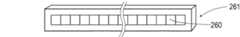
ラインセンサ261は、図2〜図4のごとく、受光量を電気的な物理量に変換する画素260が直線的に配列された1次元の撮像センサである。64個の各画素260は、受けた光に応じて電流信号を発生するフォトダイオード(受光素子)PD1のほか、積分回路(受光蓄積部)265、ホールド回路266等を個別に備えている。各画素260の物理量は、撮像データ出力部268によって順次読み出されて一連の撮像データに変換される。 As shown in FIGS. 2 to 4, the
積分回路265は、フォトダイオードPD1が発生した電流信号に応じて電荷(物理量)を蓄積し、蓄積した電荷に応じた電圧を出力する回路である。
ホールド回路266は、積分回路265が出力するピーク電圧を保持し、その大きさに応じた電圧を出力するサンプルホールド回路である。なお、ホールド回路266は、スイッチSW2を介して積分回路265と電気的に接続されている。
撮像データ出力部268は、各画素260のホールド回路266の出力電圧を1画素ずつ順番に読み出して64画素分の一連の撮像データを生成して出力する出力部である。The integrating
The
The imaging
本例のラインセンサ261では、積分回路265のコンデンサC1に対して並列接続されたスイッチSW1が電子シャッター(蓄積モード切換部)としての機能を実現している。スイッチSW1が閉状態のときには、フォトダイオードPD1が受光してもコンデンサC1に電荷が蓄えられることなく全てキャンセルされ、積分回路265の電荷がゼロ(初期値)に維持される。スイッチSW1が開状態であるときのみ、フォトダイオードPD1の受光量に応じた電荷が積分回路265に蓄積される。なお、スイッチSW1については、ラインセンサ261の非動作期間を含めて閉状態がデフォルト設定されている。スイッチSW1は、撮像制御部31(図5参照。)の制御に応じて開状態に切り換えられる。 In the
制御ユニット3は、図1及び図5のごとく、センサユニット2及びソレノイド11を制御するユニットであり、商用電源から電力の供給を受けて動作する。この制御ユニット3は、センサユニット2、ソレノイド11等を制御する制御基板30を備えている。制御基板30には、ラインセンサ261とLED素子251を制御する撮像制御部31と、ラインセンサ261による撮像データに基づいて使用者を検出する人体検出部32と、人体検出部32の検出結果に応じてソレノイド11を制御する給水制御部33と、が設けられている。 As shown in FIGS. 1 and 5, the
撮像制御部31は、動作期間と非動作期間が交互に現れる間欠動作が行われるようにラインセンサ261を制御すると共に、約1ミリ秒の動作期間の中でLED素子251を1回発光させる。本例では、時間的に隣り合う動作期間の間の非動作期間として、約0.5秒のインターバル時間が設定されている。撮像制御部31は、前回の動作期間が終了してからインターバル時間が経過するまでラインセンサ261への電源供給を停止して非動作期間を設定し、インターバル時間が経過したときに電源供給を再開して動作期間を設定する。 The
撮像制御部31は、1回の動作期間において、2回の露光期間を設定する。第1回目の露光期間は、LED素子251の発光を伴わない露光期間である。第2回目の露光期間は、LED素子251の発光を伴う露光期間である。撮像制御部31は、各露光期間の撮像データがそれぞれ出力されるようにラインセンサ261を制御する。なお、撮像制御部31による制御については、図7のタイムチャート図を参照して後で詳しく説明する。 The
人体検出部32は、ラインセンサ261が出力する撮像データを利用して被検出対象までの距離を計測し、使用者の有無を判断する。人体検出部32は、LED素子251の発光がない第1回目の露光期間の撮像データ(無発光時データ)と、LED素子251の発光を伴う第2回目の露光期間の撮像データ(発光時データ)と、を取り込んで記憶した後、図6のごとく両者の差分データを求める。周囲光に加えてLED光の下での撮像データである発光時データから、周囲光下の撮像データである無発光時データを、差し引いた差分データにおいては、周囲光の影響が抑圧されており、LED素子251の投射光に応じた反射光の成分が抽出されている。 The human
人体検出部32は、図6の差分データについて、被検出対象の反射光がラインセンサ261に入射した位置を特定し、その入射位置に応じて被検出対象までの距離を計測する。上記のごとく撮像部26は、発光部25に対して水平方向にずらして配置されている。被検出対象までの距離は、発光部25に対する撮像部26のオフセット量に基づく三角測量の原理により計測できる。
給水制御部33は、人体検出部32による使用者の検出に応じて、ソレノイド11を開弁させるための制御信号を出力する。The human
The water
以上のように構成された本例の自動給水装置1(特に、センサユニット2。)の動作について、図7のタイムチャート図を参照して説明する。このタイムチャート図では、時刻T1〜T8がセンサユニット2の1回の動作期間に対応しており、その前後の期間が非動作期間に対応している。同図中、「PWR」は、センサユニット2に対する電力制御信号であり、Hiが電力供給状態、Loが電力遮断状態に対応している。「SW1」、「SW2」等は、対応するスイッチの制御信号であり、Hiが閉状態、Loが開状態に対応している。「LED」は、LED素子251の制御信号であり、Hiが発光状態、Loが消灯状態に対応している。また、「Video」は、各画素260の画素値(受光量に応じた輝度値)が連なる1次元のデジタル画像信号よりなる撮像データを示している。 The operation of the automatic water supply apparatus 1 (particularly the sensor unit 2) of this example configured as described above will be described with reference to the time chart of FIG. In this time chart, times T1 to T8 correspond to one operation period of the
図示されない前回の動作期間が終了した後の経過時間がインターバル時間(約0.5秒)に到達するまでの非動作期間では、動作期間への移行タイミングを計るための計時動作(制御ユニット3)を除いて、自動給水装置1の動作が停止している。時刻T1で前記経過時間がインターバル時間に到達したとき、PWRがHiに切り換わりラインセンサ261(図4参照。)への電力供給が再開される。このとき、ラインセンサ261のスイッチSW1(積分回路265)は、デフォルト設定の閉状態のままとなっている。そのため、フォトダイオードPD1が受光しても積分回路265のコンデンサC1に電荷が蓄積されることなく、そのまま初期値が維持される。 In the non-operation period until the elapsed time after the end of the previous operation period (not shown) reaches the interval time (about 0.5 seconds), the time measuring operation for measuring the timing of shifting to the operation period (control unit 3) Except for, the operation of the automatic
時刻T2になると、積分回路265のスイッチSW1が開状態に切り換えられると共に、ホールド回路266の入力側のスイッチSW2が閉状態に切り換えられる。そうするとフォトダイオードPD1が出力した電荷がコンデンサーC1に蓄積されていき、これにより積分回路265の出力電圧が次第に高くなる。スイッチSW2が閉じた状態では、積分回路265の出力電圧がホールド回路266に入力され、そのピーク電圧が保持される。その後、時刻T3になったとき、スイッチSW1が閉状態に切り換えられると共に、スイッチSW2が開状態に切り換えられ、フォトダイオードPD1の第1回目の露光期間が終了する。 At time T2, the switch SW1 of the
その後、各画素のホールド回路266の出力電圧に基づいて、撮像データ出力部268が撮像データを生成する。撮像データ出力部268は、撮像制御部31(図5参照。)から取り込むクロック信号(図示略)を基準タイミングとして1クロック毎に1画素ずつ、その出力電圧を読み取りながら64画素分の撮像データを出力する。この撮像データは、前記人体検出部32により取り込まれ、周囲光下の無発光時データ(図6参照。)として記憶される。 Thereafter, the imaging
撮像データ出力部268による撮像データの出力完了後の時刻T4になると、LED素子251の発光が開始され、その発光状態は時刻T7まで継続する。その発光状態下の時刻T5〜T6では、積分回路265のスイッチSW1が再度、開状態に切り換えられると共に、ホールド回路266の入力側のスイッチSW2が閉状態に切り換えられる。そうすると、上記の場合と同様、フォトダイオードPD1の受光量に応じた物理量(ピーク電圧)がホールド回路266に保持される。時刻T5〜T6の第2回目の露光期間は、前記第1回目の露光期間と同じ長さである一方、LED素子251の発光状態である点においてのみ相違している。 At time T4 after completion of imaging data output by the imaging
その後、第1回目の露光期間の後処理と同様、各画素のホールド回路266の出力電圧に基づいて、撮像データ出力部268が撮像データを生成して出力する。この撮像データは、前記人体検出部32により取り込まれ、(周囲光+LED光)下の発光時データ(図6参照。)として記憶される。撮像データの出力が完了した後の時刻T8でPWRがLoになり、センサユニット2に対する電力供給が停止される。
なお、制御ユニット3については、使用者の検出処理や給水制御等を実行した後、次回の動作期間への移行タイミングを計るための計時動作のみが行われる低消費電力モードに移行する。Thereafter, as in the post-processing of the first exposure period, the imaging
In addition, about
以上のように構成された本例の自動給水装置1では、ラインセンサ261を含むセンサユニット2が間欠動作している。さらに、本例のラインセンサ261は電子シャッター機能を備えており、撮像データの取得時を除いて各画素260で電荷が蓄積されないようになっている。それ故、撮像データを取得するに先立って、ラインセンサ261の各画素260に蓄積された物理量を読み出してリセットする必要がない。この自動給水装置1では、各画素260のリセットに必要な動作時間を削減でき、ラインセンサ261の動作時間が一層短くなっている。 In the automatic
このように、本例の自動給水装置1は、ラインセンサ261の採用により誤検出を低減しつつ、その消費電力を抑えて省エネ効果を高めた優れた特性の装置である。
なお、本例は、各画素260の電荷蓄積を回避するための蓄積モード切換部として、電子シャッターを採用した例である。これに代えて、各画素のフォトダイオードPD1に対する光の入射を遮断する機械式シャッターを採用しても良い。Thus, the automatic
In this example, an electronic shutter is employed as an accumulation mode switching unit for avoiding charge accumulation in each
なお、本例は、洗面台15の水栓16に自動給水装置1を適用した例であるが、キッチン等の水栓であっても良い。
なお、本例では、センサユニット2と制御ユニット3とを別体にて構成している。これに代えて、センサユニット2と制御ユニット3とを一体的に構成し、水栓16に収容することも良い。In addition, although this example is an example which applied the automatic
In this example, the
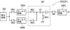
なお、本例は、図6のごとく、センサユニット2の1回の動作期間において、ラインセンサ261による撮像動作を2回実行して発光時データと無発光時データを取得し、それらの差分データに基づいて検出処理を実行した例である。これに代えて、LED素子251の発光下で蓄積された物理量と、非発光下で蓄積された物理量と、の差分の物理量を各画素260から直接出力させることも良い。この場合には、LED素子251の発光有る無しの差分の撮像データを直接出力できる。このような構成は、例えば、図8のような回路構成を備えたラインセンサ261により実現できる。 In this example, as shown in FIG. 6, in the single operation period of the
同図のラインセンサ261の各画素260では、ホールド回路266A・BがスイッチSW21、SW22を介して積分回路265に接続されている。さらに、ホールド回路266A・Bの下流側には、差分演算回路267が接続され、さらに、その下流側に出力用のホールド回路266Cが接続されている。このラインセンサ261の動作の概略を図9のタイムチャート図を利用して説明する。 In each
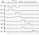
図9のタイムチャート図の例では、LED素子251(図4参照。)の発光を伴わない第1回目の露光期間が時刻T1〜T2に設定され、発光を伴う第2の露光期間が時刻T4〜T5に設定されている(LED素子251の発光期間は時刻T3〜T6)。積分回路265のスイッチSW1(図4参照。)が開状態に切り換えられると共に、ホールド回路266Aの入力側のスイッチSW21が閉状態に切り換えられる第1回目の露光期間では、積分回路265のピーク電圧がホールド回路266Aに保持される。一方、積分回路265のスイッチSW1が開状態に切り換えられると共に、ホールド回路266Bの入力側のスイッチSW22が閉状態に切り換えられる第2回目の露光期間では、積分回路265のピーク電圧がホールド回路266Bに保持される。 In the example of the time chart of FIG. 9, the first exposure period without light emission of the LED element 251 (see FIG. 4) is set at times T1 to T2, and the second exposure period with light emission is at time T4. To T5 (the light emission period of the
時刻T7になったとき、スイッチSW31、SW33が閉状態に切り換えられ、時刻T8までこのスイッチ状態が維持される。この時刻T7〜T8までの期間では、ホールド回路266Aの出力電圧(電圧値V1)がスイッチSW31を介して差分演算回路267のコンデンサC3に入力されて保持される。
その後、時刻T9になったとき、スイッチSW32が閉状態に切り換えられ(スイッチSW33については開状態のまま)、時刻T10までこのスイッチ状態が維持される。この時刻T9〜T10までの期間では、ホールド回路266Bの出力電圧(電圧値V2)がスイッチSW32を介して差分演算回路267のコンデンサC3に入力される。このとき、スイッチSW33が開状態のままであるため、差分演算回路267のコンデンサC3には、電圧値V1と電圧値V2との差分が保持されることになる。この差分の電圧値は、LED素子251の投射光に基づく反射光成分に相当している。この差分の電圧値は、時刻T11〜T12でホールド回路266Cに取り込まれ、その後、図8には図示されない撮像データ出力部268(図4参照。)を介して撮像データとして出力される。At time T7, the switches SW31 and SW33 are switched to the closed state, and this switch state is maintained until time T8. During the period from time T7 to time T8, the output voltage (voltage value V1) of the
Thereafter, when time T9 is reached, the switch SW32 is switched to the closed state (the switch SW33 remains open), and this switch state is maintained until time T10. During the period from time T9 to time T10, the output voltage (voltage value V2) of the
(実施例2)
本例は、自動洗浄機能付きの小便器100に適用される自動給水装置1に関する例である。この内容について、図10〜図13を用いて説明する。
自動給水装置1は、図10及び図11のごとく、使用者を検出して小便器100の洗浄動作を行う装置である。この自動給水装置1は、小便器100に近づいて来た使用者を検出したときに少量の水で予備洗浄動作を実行し、使用者が小便器100から立ち去ったとき本洗浄を実行する。(Example 2)
This example is an example relating to the automatic
As shown in FIGS. 10 and 11, the automatic
本例の自動給水装置1は、小便器100の使用者の正面に当たる壁面101に配設された検出ボックス4と、給水バルブであるソレノイド11と、給水配管12の途中に介設された水流発電機14と、水流発電機14が発電した電力を蓄える蓄電池13と、を含んで構成されている。ソレノイド11と給水配管12との組合せにより給水部が形成され、水流発電機14と蓄電池13との組合せにより発電部が形成されている。 The automatic
ソレノイド11は、小便器100の内側上部に位置する吐水口120に連通する給水配管12の途中に設けられた電磁弁である。本例の自動給水装置1では、ソレノイド11の上流側に水流発電機14が設けられている。水流発電機14で発電された電力は、一旦、蓄電池13に蓄えられて検出ボックス4に供給される。 The
検出ボックス4は、図10〜図12のごとく、使用者を検出して小便器100に洗浄水を供給するための制御ボックスである。検出ボックス4は、LED素子451、ラインセンサ461、制御基板40等を筐体480に収めた略箱状の部品であり、トイレルームに面する側に検出面48が形成されている。 The detection box 4 is a control box for detecting a user and supplying wash water to the
検出面48は、金属光沢を呈するように表面処理された外枠481と、赤外領域の光を選択的に透過する樹脂製のフィルタ板482と、により形成されている。検出ボックス4は、トイレルームの壁面101に対して検出面48が略面一をなすように配置される。
検出面48を構成するフィルタ板482の内側には、LED素子451と投光レンズ455とを含む発光部45、及びラインセンサ461と集光レンズ465とを含む撮像部46が配設されている。
なお、その他の構成及び作用効果については、実施例1と同様である。The
Inside the
Other configurations and operational effects are the same as those in the first embodiment.
なお、本例から水流発電機14を省略すると共に、蓄電池13に代わる使い切りの電池によって自動給水装置を動作させることも良い。この場合には、電池を交換できるように電池ボックス(電池収容部)を設ける必要がある。さらに、商用電源を利用可能な適用環境にあれば、商用電源から電力を供給して自動給水装置を動作させても良い。 In addition, while omitting the water
なお、本例の自動給水装置1に基づいて、図13のごとく、発光部45を撮像部46Bに置き換えることもできる。撮像部46A・Bが出力する撮像データ間の位相差は、いわゆるステレオカメラの視差に相当している。この視差に基づけば、ステレオ視の原理により撮像対象までの距離を計測でき、本例と同様に使用者を検出できる。撮像部46が一対必要なステレオ視の場合、ラインセンサ461の消費電力を抑制できるという効果が一層有効になる。
さらに、発光部45を省略する一方、撮像部46が取得した撮像データに画像処理を施す画像処理手段を設けることも良い。この場合には、撮像データに画像処理を施して人体を認識することにより使用者を検出することが可能である。In addition, based on the automatic
Furthermore, it is also possible to provide image processing means for performing image processing on the imaging data acquired by the
以上、実施例1及び2のごとく本発明の具体例を詳細に説明したが、これらの具体例は、特許請求の範囲に包含される技術の一例を開示しているにすぎない。言うまでもなく、具体例の構成や数値等によって、特許請求の範囲が限定的に解釈されるべきではない。特許請求の範囲は、公知技術や当業者の知識等を利用して前記具体例を多様に変形あるいは変更した技術を包含している。 Although specific examples of the present invention have been described in detail as in the first and second embodiments, these specific examples merely disclose an example of the technology included in the scope of claims. Needless to say, the scope of the claims should not be construed as limited by the configuration, numerical values, or the like of the specific examples. The scope of the claims includes techniques obtained by variously modifying or changing the specific examples using known techniques, knowledge of those skilled in the art, and the like.
1…自動給水装置、15…洗面台、16…水栓、100…小便器、11…ソレノイド、12…給水配管、14…水流発電機(発電部)、2…センサユニット、25、45…発光部、251、451…LED素子、26、46…撮像部、260…画素、261、461…ラインセンサ、265…積分回路(受光蓄積部)、266…ホールド回路、268…撮像データ出力部、3…制御ユニット、30、40…制御基板、31、41…撮像制御部、32、42…人体検出部、33、43…給水制御部、SW1…電子シャッター(蓄積モード切換部) DESCRIPTION OF
Claims (3)
Translated fromJapanese前記撮像部は、受けた光を電気信号に変換する画素毎の受光素子と、該受光素子の電気信号を取り込んで電気的な物理量を蓄積するように画素毎に設けられた受光蓄積部と、各画素の受光蓄積部が蓄積した物理量に基づく前記撮像データを出力する撮像データ出力部と、前記受光蓄積部に物理量が蓄積される蓄積状態、及び蓄積されない非蓄積状態のうちの一方の状態を択一的に設定する蓄積モード切換部と、を有し、
前記撮像制御部は、動作期間及び非動作期間が交互に現れる間欠動作が行われるように前記撮像部を制御すると共に、
前記動作期間において、前記撮像データを取得するときのみ前記蓄積状態が設定され、それ以外では前記非蓄積状態が設定されるように前記蓄積モード切換部を制御する自動給水装置。An imaging unit that converts light received by each pixel arranged one-dimensionally or two-dimensionally into an electrical signal to acquire one-dimensional or two-dimensional imaging data; an imaging control unit that controls the imaging unit; An automatic water supply apparatus comprising: a human body detection unit that detects a human body using imaging data acquired by an imaging unit; and a water supply control unit that controls the water supply unit so that water is supplied in response to detection of the human body. There,
The imaging unit includes a light receiving element for each pixel that converts received light into an electric signal, a light receiving accumulation unit provided for each pixel so as to accumulate an electrical physical quantity by taking in the electric signal of the light receiving element, One state of an imaging data output unit that outputs the imaging data based on the physical quantity accumulated by the light receiving and accumulating unit of each pixel, an accumulation state in which the physical quantity is accumulated in the light receiving accumulation unit, and a non-accumulating state that is not accumulated An accumulation mode switching unit that is alternatively set;
The imaging control unit controls the imaging unit so that an intermittent operation in which an operation period and a non-operation period appear alternately is performed,
An automatic water supply apparatus that controls the accumulation mode switching unit so that the accumulation state is set only when the imaging data is acquired during the operation period, and the non-accumulation state is set otherwise.
前記人体検出部は、当該2基の撮像部が取得した撮像データ間の位相ズレである視差に基づき、ステレオ視の原理により被検出対象までの距離を計測して人体を検出する自動給水装置。In Claim 1 or 2, two said imaging parts are provided at predetermined intervals,
The said human body detection part is an automatic water supply apparatus which detects the human body by measuring the distance to a to-be-detected object by the principle of a stereo vision based on the parallax which is the phase shift between the imaging data which the said 2 imaging parts acquired.
Priority Applications (5)
| Application Number | Priority Date | Filing Date | Title |
|---|---|---|---|
| JP2011074465AJP5775721B2 (en) | 2011-03-30 | 2011-03-30 | Automatic water supply device |
| CN201180046164.2ACN103119475B (en) | 2010-09-30 | 2011-09-28 | Human body sensor and automatic faucet |
| PCT/JP2011/072252WO2012043663A1 (en) | 2010-09-30 | 2011-09-28 | Human body detection sensor and automatic faucet |
| PH1/2013/500575APH12013500575A1 (en) | 2010-09-30 | 2011-09-28 | Human body detection sensor and automatic faucet |
| TW100135288ATWI592545B (en) | 2010-09-30 | 2011-09-29 | Sensing body sensors and automatic faucets |
Applications Claiming Priority (1)
| Application Number | Priority Date | Filing Date | Title |
|---|---|---|---|
| JP2011074465AJP5775721B2 (en) | 2011-03-30 | 2011-03-30 | Automatic water supply device |
Publications (2)
| Publication Number | Publication Date |
|---|---|
| JP2012207468Atrue JP2012207468A (en) | 2012-10-25 |
| JP5775721B2 JP5775721B2 (en) | 2015-09-09 |
Family
ID=47187431
Family Applications (1)
| Application Number | Title | Priority Date | Filing Date |
|---|---|---|---|
| JP2011074465AActiveJP5775721B2 (en) | 2010-09-30 | 2011-03-30 | Automatic water supply device |
Country Status (1)
| Country | Link |
|---|---|
| JP (1) | JP5775721B2 (en) |
Cited By (5)
| Publication number | Priority date | Publication date | Assignee | Title |
|---|---|---|---|---|
| CN104871034A (en)* | 2012-12-28 | 2015-08-26 | 骊住株式会社 | Motion detection sensor and automatic faucet |
| KR101799328B1 (en)* | 2016-05-17 | 2017-11-20 | (주) 티에스자바 | PSD Sensor System to control on and off of Faucet and Method thereof |
| JP2019053072A (en)* | 2013-06-27 | 2019-04-04 | 株式会社リコー | Distance measuring device, vehicle, and distance measuring device calibration method |
| JP2019203735A (en)* | 2018-05-22 | 2019-11-28 | 株式会社神戸製鋼所 | Distance measuring device and distance measuring method |
| JP2024516265A (en)* | 2021-04-29 | 2024-04-12 | 上海禾賽科技有限公司 | Method for measuring the reflectivity of a target using a laser radar and laser radar |
Citations (6)
| Publication number | Priority date | Publication date | Assignee | Title |
|---|---|---|---|---|
| JPH06173311A (en)* | 1992-12-10 | 1994-06-21 | Energy Support Corp | Automatic water feeder |
| JP2002212990A (en)* | 2001-01-19 | 2002-07-31 | San-Ei Faucet Mfg Co Ltd | Automatic feed water method in washing device and automatic feed water mechanism in the washing device |
| JP2004183255A (en)* | 2002-11-29 | 2004-07-02 | Inax Corp | Water supply control system |
| JP2005207012A (en)* | 2004-01-20 | 2005-08-04 | Seiko Precision Inc | Automatic faucet and detecting sensor |
| JP2008039491A (en)* | 2006-08-02 | 2008-02-21 | Fuji Heavy Ind Ltd | Stereo image processing device |
| JP2008151659A (en)* | 2006-12-18 | 2008-07-03 | Fuji Heavy Ind Ltd | Object detection device |
- 2011
- 2011-03-30JPJP2011074465Apatent/JP5775721B2/enactiveActive
Patent Citations (6)
| Publication number | Priority date | Publication date | Assignee | Title |
|---|---|---|---|---|
| JPH06173311A (en)* | 1992-12-10 | 1994-06-21 | Energy Support Corp | Automatic water feeder |
| JP2002212990A (en)* | 2001-01-19 | 2002-07-31 | San-Ei Faucet Mfg Co Ltd | Automatic feed water method in washing device and automatic feed water mechanism in the washing device |
| JP2004183255A (en)* | 2002-11-29 | 2004-07-02 | Inax Corp | Water supply control system |
| JP2005207012A (en)* | 2004-01-20 | 2005-08-04 | Seiko Precision Inc | Automatic faucet and detecting sensor |
| JP2008039491A (en)* | 2006-08-02 | 2008-02-21 | Fuji Heavy Ind Ltd | Stereo image processing device |
| JP2008151659A (en)* | 2006-12-18 | 2008-07-03 | Fuji Heavy Ind Ltd | Object detection device |
Cited By (8)
| Publication number | Priority date | Publication date | Assignee | Title |
|---|---|---|---|---|
| CN104871034A (en)* | 2012-12-28 | 2015-08-26 | 骊住株式会社 | Motion detection sensor and automatic faucet |
| US9758952B2 (en) | 2012-12-28 | 2017-09-12 | Lixil Corporation | Human body detection sensor and automatic faucet |
| JP2019053072A (en)* | 2013-06-27 | 2019-04-04 | 株式会社リコー | Distance measuring device, vehicle, and distance measuring device calibration method |
| KR101799328B1 (en)* | 2016-05-17 | 2017-11-20 | (주) 티에스자바 | PSD Sensor System to control on and off of Faucet and Method thereof |
| JP2019203735A (en)* | 2018-05-22 | 2019-11-28 | 株式会社神戸製鋼所 | Distance measuring device and distance measuring method |
| JP7077138B2 (en) | 2018-05-22 | 2022-05-30 | 株式会社神戸製鋼所 | Distance measuring device and distance measuring method |
| JP2024516265A (en)* | 2021-04-29 | 2024-04-12 | 上海禾賽科技有限公司 | Method for measuring the reflectivity of a target using a laser radar and laser radar |
| JP7652934B2 (en) | 2021-04-29 | 2025-03-27 | 上海禾賽科技有限公司 | Method for measuring the reflectivity of a target using a laser radar and laser radar |
Also Published As
| Publication number | Publication date |
|---|---|
| JP5775721B2 (en) | 2015-09-09 |
Similar Documents
| Publication | Publication Date | Title |
|---|---|---|
| WO2012043663A1 (en) | Human body detection sensor and automatic faucet | |
| JP5775721B2 (en) | Automatic water supply device | |
| US20150259890A1 (en) | Human body detection sensor and automatic faucet | |
| CN104871034B (en) | Motion detection sensor and automatic faucet | |
| JP6169935B2 (en) | Automatic faucet | |
| CN103297714B (en) | Circuit arrangements and methods for time-of-flight sensor | |
| CN103575406B (en) | There is the thermal imaging camera of intermittent image capture | |
| WO2014192230A1 (en) | Proximity sensor and automatic faucet | |
| US20180124372A1 (en) | Systems And Methods For Active Depth Imager With Background Subtract | |
| JP5722688B2 (en) | Human body detection sensor and automatic faucet | |
| TWI518556B (en) | Navigation device and power saving method thereof | |
| WO2009058468A1 (en) | Self-triggering cmos image sensor | |
| CN106454156A (en) | Image sensor and operating method thereof | |
| WO2006080004A3 (en) | Method and system for x-ray radiation imaging | |
| US10602073B2 (en) | Global pixel binning for ambient light sensing | |
| JP6008540B2 (en) | Human body detection sensor and automatic faucet | |
| JP2007256064A (en) | Water faucet control system | |
| JP5909171B2 (en) | Human body detection sensor and automatic faucet | |
| JP5947739B2 (en) | Automatic faucet | |
| US20230014474A1 (en) | Light receiving device, method of controlling light receiving device, and electronic apparatus | |
| Xiang et al. | A Token-Passing-Based Trigger-Prediction Methodology for Event-Driven ToF Sensors | |
| JP2023142067A (en) | Image acquisition device and toilet system | |
| HK1199999A1 (en) | Image sensor with integrated ambient light detection |
Legal Events
| Date | Code | Title | Description |
|---|---|---|---|
| A621 | Written request for application examination | Free format text:JAPANESE INTERMEDIATE CODE: A621 Effective date:20131226 | |
| A131 | Notification of reasons for refusal | Free format text:JAPANESE INTERMEDIATE CODE: A131 Effective date:20141111 | |
| A521 | Written amendment | Free format text:JAPANESE INTERMEDIATE CODE: A523 Effective date:20150108 | |
| TRDD | Decision of grant or rejection written | ||
| A01 | Written decision to grant a patent or to grant a registration (utility model) | Free format text:JAPANESE INTERMEDIATE CODE: A01 Effective date:20150630 | |
| A61 | First payment of annual fees (during grant procedure) | Free format text:JAPANESE INTERMEDIATE CODE: A61 Effective date:20150706 | |
| R150 | Certificate of patent or registration of utility model | Ref document number:5775721 Country of ref document:JP Free format text:JAPANESE INTERMEDIATE CODE: R150 | |
| S111 | Request for change of ownership or part of ownership | Free format text:JAPANESE INTERMEDIATE CODE: R313111 | |
| R350 | Written notification of registration of transfer | Free format text:JAPANESE INTERMEDIATE CODE: R350 |