JP2012203113A - Head-mounted display device - Google Patents
Head-mounted display deviceDownload PDFInfo
- Publication number
- JP2012203113A JP2012203113AJP2011066168AJP2011066168AJP2012203113AJP 2012203113 AJP2012203113 AJP 2012203113AJP 2011066168 AJP2011066168 AJP 2011066168AJP 2011066168 AJP2011066168 AJP 2011066168AJP 2012203113 AJP2012203113 AJP 2012203113A
- Authority
- JP
- Japan
- Prior art keywords
- optical surface
- light guide
- head
- guide prism
- display device
- Prior art date
- Legal status (The legal status is an assumption and is not a legal conclusion. Google has not performed a legal analysis and makes no representation as to the accuracy of the status listed.)
- Granted
Links
- 230000003287optical effectEffects0.000claimsabstractdescription217
- 210000001747pupilAnatomy0.000claimsabstractdescription25
- 230000001154acute effectEffects0.000claimsabstractdescription4
- 230000007246mechanismEffects0.000claimsdescription16
- 230000004907fluxEffects0.000claimsdescription12
- 210000003128headAnatomy0.000claimsdescription8
- 230000031700light absorptionEffects0.000claimsdescription2
- 230000000694effectsEffects0.000description8
- 210000001508eyeAnatomy0.000description6
- 210000005252bulbus oculiAnatomy0.000description5
- 238000010586diagramMethods0.000description5
- 239000011521glassSubstances0.000description3
- 230000008859changeEffects0.000description2
- 230000000007visual effectEffects0.000description2
- 241000282412HomoSpecies0.000description1
- 238000013459approachMethods0.000description1
- 230000005540biological transmissionEffects0.000description1
- 238000006073displacement reactionMethods0.000description1
- 238000002347injectionMethods0.000description1
- 239000007924injectionSubstances0.000description1
- 239000004973liquid crystal related substanceSubstances0.000description1
- 238000010422paintingMethods0.000description1
- 230000001681protective effectEffects0.000description1
- 230000001179pupillary effectEffects0.000description1
- 239000004576sandSubstances0.000description1
- 238000004381surface treatmentMethods0.000description1
- 230000009466transformationEffects0.000description1
Images


Classifications
- G—PHYSICS
- G02—OPTICS
- G02B—OPTICAL ELEMENTS, SYSTEMS OR APPARATUS
- G02B27/00—Optical systems or apparatus not provided for by any of the groups G02B1/00 - G02B26/00, G02B30/00
- G02B27/01—Head-up displays
- G02B27/017—Head mounted
- G02B27/0172—Head mounted characterised by optical features
- G—PHYSICS
- G02—OPTICS
- G02B—OPTICAL ELEMENTS, SYSTEMS OR APPARATUS
- G02B27/00—Optical systems or apparatus not provided for by any of the groups G02B1/00 - G02B26/00, G02B30/00
- G02B27/01—Head-up displays
- G02B27/017—Head mounted
- G02B2027/0178—Eyeglass type
Landscapes
- Physics & Mathematics (AREA)
- General Physics & Mathematics (AREA)
- Optics & Photonics (AREA)
- Lenses (AREA)
Abstract
Translated fromJapaneseDescription
Translated fromJapanese本発明は、頭部装着型表示装置に関するものである。 The present invention relates to a head-mounted display device.
映像表示素子から射出した映像光を導光するための導光プリズムと、映像表示素子の映像を虚像として観察するための接眼レンズとを組み合わせることで、視野の目の前に空中像として表示映像を観察する頭部装着型表示装置が知られている。 By combining a light guide prism for guiding the image light emitted from the image display element and an eyepiece lens for observing the image of the image display element as a virtual image, the image is displayed as an aerial image in front of the field of view. A head-mounted display device for observing the image is known.
特に、屋外でも使用する頭部装着型表示装置では、装置の小型化が重要であり、例えば、映像表示素子と導光プリズムとを分離して、眼鏡の異なる部分(フレームやレンズ等)により保持する装置が提案されている(例えば、特許文献1参照)。この場合、映像表示素子による映像を観察者が適切な位置で観察するには、映像表示素子、導光プリズム、および、接眼レンズを適切な相対位置関係で保持することが重要となる。また、装着者の頭部寸法は、頭幅、瞳孔距離(眼幅)、耳から眼球までの距離等に個人差があるので、個人に応じた調整も必要とされる。そこで、特許文献1では、導光プリズムと映像表示素子との相対位置関係を調整する調整機構を設けている。 In particular, in a head-mounted display device used outdoors, it is important to reduce the size of the device. For example, the image display element and the light guide prism are separated and held by different parts of the glasses (frame, lens, etc.). An apparatus has been proposed (see, for example, Patent Document 1). In this case, in order for an observer to observe an image on the image display element at an appropriate position, it is important to hold the image display element, the light guide prism, and the eyepiece lens in an appropriate relative positional relationship. In addition, since the head size of the wearer has individual differences in the head width, pupil distance (eye width), distance from the ear to the eyeball, etc., adjustment according to the individual is also required. Therefore, in Patent Document 1, an adjustment mechanism for adjusting the relative positional relationship between the light guide prism and the video display element is provided.
また、導光プリズムを用いた特許文献1の頭部装着型表示装置では、映像表示素子から出射された映像光を、導光プリズムの一端側から入射させ、導光プリズム内で奇数回ジグザグに反射させて、他端部からエアギャップを介して接眼レンズに入射させることにより、眼球に向けて射出している。映像光を導光プリズム内にジグザグに通すことによって、導光プリズムに映像光を入射させる入射部の幅を広く取りながら、導光プリズムの視線方向の厚さを狭くすることができる。 In the head-mounted display device of Patent Document 1 using a light guide prism, image light emitted from the image display element is incident from one end side of the light guide prism, and is zigzag odd times in the light guide prism. The light is reflected and incident on the eyepiece lens through the air gap from the other end, and is emitted toward the eyeball. By allowing the image light to pass through the light guide prism in a zigzag manner, it is possible to reduce the thickness of the light guide prism in the line-of-sight direction while widening the width of the incident portion for allowing the image light to enter the light guide prism.
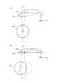
特許文献1のように、導光プリズム内での反射の回数を奇数回とすると、偶数回反射の場合と比較して導光プリズムと映像表示素子との相対移動によって、より大きな瞳位置の調整効果が得られる。図7は、映像表示素子101および映像光を射出する射出部に接眼レンズ103が固定された導光プリズム102を含む頭部装着型表示装置において、映像表示素子101と導光プリズムとを相対変位させて瞳位置の調整を行う場合の光路の変化を示している。図7(a)では、導光プリズム102内を映像光が偶数回(2回)反射し、図7(b)では奇数回(5回)反射している。図中、実線および鎖線はそれぞれ移動前および移動後の構成および光軸経路を表し、導光プリズム102を、固定された映像表示素子101に対して略平行に移動させている。図7から明らかなように、導光プリズム102内で2回反射の場合は、導光プリズム102の移動幅L1に対して眼幅調整幅L2が小さく、導光プリズム102内で5回反射の場合は、導光プリズム102の移動幅L1に対して眼幅調整幅L3が大きくなる。すなわち、導光プリズム内で奇数回反射する場合は、僅かな機械的調整量で大きな眼幅調整効果を得ることができる。When the number of reflections in the light guide prism is an odd number as in Patent Document 1, a larger pupil position adjustment is made by relative movement between the light guide prism and the image display element than in the case of even number reflection. An effect is obtained. FIG. 7 shows a relative displacement between the
図8は、図7(b)で示した光学系を通る光の光路を説明する図である。この図から分かるように、導光プリズムの102の映像光の入射部102a(図の両矢印により、導光プリズムの面の対応する一部分を示すものとする)と射出部102cとは、略垂直に入射する光を透過させ、また、プリズム内を導光される光を全反射する透過反射面となっている。このため、入射部では透過面102aと反射面102b1とが1つの連続面となっているため、映像表示素子101と導光プリズム102とを相対的に変位させても、互いの有効領域によりケラレが発生することなく光線を通すことができる。一方、接眼レンズが配置された射出部102cにおいては、導光プリズム102での全反射をする面102b2と、接眼レンズへ映像光を射出する透過面102cとが重複するため、導光プリズム102と接眼レンズ103との間に空気層(エアギャップ)を設けることが必要となる。FIG. 8 is a diagram for explaining an optical path of light passing through the optical system shown in FIG. As can be seen from this figure, the image
しかし、このような頭部装着型表示装置では、エアギャップを設けたことにより、導光プリズムに対して接眼レンズを保持するために外装筐体や複雑な保持機構が必要となる。エアギャップを設けずに、瞳孔プリズム内を映像光を入射側と出射側の斜面で2回反射させて接眼レンズから出射させる構成もあるが、その場合は広い瞳位置調整幅を得ることができない。 However, in such a head-mounted display device, since the air gap is provided, an exterior housing and a complicated holding mechanism are required to hold the eyepiece lens with respect to the light guide prism. There is a configuration in which the image light is reflected twice on the entrance side and exit side slopes and emitted from the eyepiece without providing an air gap, but in this case, a wide pupil position adjustment width cannot be obtained. .
したがって、これらの点に着目してなされた本発明の目的は、広い入射部を確保しつつ、射出部の空気層を必要とせず接眼レンズの保持が容易に行える頭部装着型表示装置を提供することにある。 Accordingly, an object of the present invention made by paying attention to these points is to provide a head-mounted display device that can easily hold an eyepiece without requiring an air layer of an emitting portion while securing a wide incident portion. There is to do.
上記目的を達成する請求項1に係る頭部装着型表示装置の発明は、
それぞれ対向する第1光学面および第2光学面と、第3光学面および第4光学面と、第5光学面および第6光学面とを有し、装着状態において前記第1光学面は装着者側に面し、前記第3光学面および前記第4光学面は前記第1光学面と鋭角の内角を形成し、前記第5および第6光学面は、それぞれ第1、第2、第3および第4光学面と接する、多面体形状の導光プリズムと、
映像光を前記導光プリズムの前記第1光学面の入射部に向けて出射する映像表示部と、
前記導光プリズムの前記第1光学面の射出部に接合されまたは一体に形成された接眼レンズとを備え、
前記導光プリズムは、前記第1光学面の前記入射部に入射した前記映像光が、前記第3光学面で反射され、前記第1光学面と前記第2光学面との間で合わせて奇数回反射された後、前記第4光学面で反射され、前記接眼レンズを透過して、該接眼レンズの光軸上にある装着者の瞳孔方向へ射出されるように構成され、
前記第1光学面の前記入射部と前記反射部とはその一部が重なっており、かつ、前記射出部は前記反射部と重ならないことを特徴とするものである。
ここで、「対向する」とは、向かい合って配置することを意味し、2面が平行である場合と、傾きを有して配置されている場合との双方を含む。The invention of the head-mounted display device according to claim 1, which achieves the above object,
The first optical surface and the second optical surface, the third optical surface and the fourth optical surface, and the fifth optical surface and the sixth optical surface, respectively, which are opposed to each other, and the first optical surface is a wearer in a wearing state. Facing the side, the third optical surface and the fourth optical surface form an acute inner angle with the first optical surface, and the fifth and sixth optical surfaces are respectively the first, second, third and A polyhedral light guide prism in contact with the fourth optical surface;
An image display unit that emits image light toward an incident portion of the first optical surface of the light guide prism;
An eyepiece lens joined to or integrally formed with the exit portion of the first optical surface of the light guide prism;
In the light guide prism, the image light incident on the incident portion of the first optical surface is reflected by the third optical surface, and is odd between the first optical surface and the second optical surface. After being reflected once, it is reflected by the fourth optical surface, is transmitted through the eyepiece, and is emitted toward the wearer's pupil on the optical axis of the eyepiece,
The incident part and the reflection part of the first optical surface are partially overlapped, and the emission part does not overlap the reflection part.
Here, “facing” means that they are arranged to face each other, and includes both cases where the two surfaces are parallel and cases where they are arranged with an inclination.
前記導光プリズムは、前記第3光学面で反射された前記映像光が、前記第1光学面の反射部で1回反射された後、前記第4光学面で反射されるように構成されることが好ましく、前記映像光の光軸が前記第1光学面の前記反射部で反射される位置は、前記第1光学面の前記第3光学面および前記第4光学面と接する2つの辺の間の中心よりも前記入射部側に位置することが好ましい。さらに好適には、前記第2光学面は光吸収面とすることができる。 The light guide prism is configured such that the image light reflected by the third optical surface is reflected once by the reflecting portion of the first optical surface and then reflected by the fourth optical surface. Preferably, the position at which the optical axis of the image light is reflected by the reflecting portion of the first optical surface is between two sides of the first optical surface in contact with the third optical surface and the fourth optical surface. It is preferable to be located closer to the incident part than the center between. More preferably, the second optical surface can be a light absorbing surface.
あるいは、前記導光プリズム内の前記装着者の前記瞳孔方向へ出射される前記映像光が透過しない、前記第2光学面を含む部分を切り欠いて、該切り欠かれた部分の表面を光吸収面としても良い。 Alternatively, a portion including the second optical surface that does not transmit the image light emitted toward the pupil of the wearer in the light guide prism is cut out, and the surface of the cut-out portion absorbs light. It is good as a surface.
また、前記接眼レンズの位置を、前記映像表示部を出射して前記装着者の前記瞳孔方向へ射出される前記映像光の光束の開口絞りとすることが好ましい。 Moreover, it is preferable that the position of the eyepiece lens is an aperture stop of the luminous flux of the image light emitted from the image display unit and emitted toward the pupil of the wearer.
さらに、前記導光プリズムの前記第1光学面が、前記映像光の前記射出部からの出射面の法線方向を前記装着者の瞳孔に向けるように、前記射出部と前記反射部との間で屈曲していても良い。 Further, the first optical surface of the light guide prism is disposed between the emitting portion and the reflecting portion so that the normal direction of the emitting surface from the emitting portion of the image light is directed to the pupil of the wearer. It may be bent.
また、好ましくは、前記映像表示部に対して前記導光プリズムを、前記映像表示部から出射される前記映像光の出射方向を横切る方向に移動させるスライド機構を備えることができる。 Preferably, the image display unit may include a slide mechanism that moves the light guide prism in a direction crossing an emission direction of the image light emitted from the image display unit.
さらに、前記第1光学面の前記射出部の少なくとも一方の幅は、人間の平均的な瞳孔径である4mmよりも小さいことが好ましい。 Furthermore, it is preferable that the width of at least one of the exit portions of the first optical surface is smaller than 4 mm which is an average human pupil diameter.
本発明によれば、導光プリズムを、第1光学面の入射部と反射部とはその一部が重なっており、かつ、射出部は反射部と重ならないように構成し、接眼レンズを導光プリズムの第1光学面の射出部に接合されまたは一体に形成したので、広い入射部を確保しつつ、射出部の空気層を必要とせず接眼レンズの保持が容易に行える頭部装着型表示装置を提供することができる。 According to the present invention, the light guide prism is configured such that the incident portion and the reflection portion of the first optical surface partially overlap each other, and the emission portion does not overlap the reflection portion, thereby guiding the eyepiece. Since it is joined or integrally formed with the exit portion of the first optical surface of the optical prism, a head-mounted display that can easily hold the eyepiece without requiring an air layer of the exit portion while ensuring a wide entrance portion. An apparatus can be provided.
以下、本発明の実施の形態について、図面を参照して説明する。 Embodiments of the present invention will be described below with reference to the drawings.
(第1実施の形態)
図1は、本発明の第1実施の形態に係る頭部装着型表示装置10を眼鏡60に装着した状態を模式的に示す平面図である。頭部装着型表示装置10は、主として本体部20および導光プリズム30と接眼レンズ40とから構成される接眼光学部を備える。頭部装着型表示装置10を眼鏡60に取り付ける場合、本体部20は、装着者の頭部に装着される眼鏡60のフレーム61の右側テンプルに、支持部20a等により取り付けられる。(First embodiment)
FIG. 1 is a plan view schematically showing a state in which the head-mounted display device 10 according to the first embodiment of the present invention is mounted on the spectacles 60. The head-mounted display device 10 includes an eyepiece optical unit mainly including a
本体部20は、眼鏡60のフレーム61に沿い装着者の前方へ延び、その先端は
、右側眼鏡レンズ62の側方で、後述する取付部50を介して導光プリズム30と連結されている。導光プリズム30は、眼鏡60の右側眼鏡レンズ62の前方を、取付部50から装着者の視野内まで略水平に延びている。後述するように、導光プリズム30は、本体部20から射出される映像光を導光し、先端に固定された接眼レンズ40から眼球70に向けて射出する。The
図2は、図1の頭部装着型表示装置の光学系の構成を導光される光束とともに模式的に示す図である。図2(a)は、図1において装着者の頭部側から見た上面図であり、図2(b)は図1において装着者と対面する側から見た正面図である。この光学系は、映像表示部である映像表示素子21、導光プリズム30および接眼レンズ40を含んで構成される。 FIG. 2 is a diagram schematically showing the configuration of the optical system of the head-mounted display device of FIG. 1 together with the guided light beam. 2A is a top view seen from the head side of the wearer in FIG. 1, and FIG. 2B is a front view seen from the side facing the wearer in FIG. The optical system includes a
映像表示素子21は、観察すべき画像を表示する液晶表示素子や有機EL素子等の素子であり、本体部20の筐体内に搭載されている。この映像表示素子21に表示された映像の映像光は、導光プリズム30に入射させるようになっている。なお、映像表示素子21を保護するための保護窓を映像表示素子21の素子面近傍に設けることが好ましい。 The
導光プリズム30は、プラスチックやガラス等からなるプリズムであり、本体部20に固定された図1の取付部50によりスライド可能に支持されている。なお、取付部50に対してスライドする導光プリズム30の端部は、外周を覆う筐体に収納されていても良い。 The
導光プリズム30は、第1光学面31、第2光学面32、第3光学面33、第4光学面34、第5光学面35および第6光学面36を有する6面体プリズムである。第1光学面31と第2光学面32とは、6面体における対向面であり、互いに略平行な面を構成している。第3光学面33と第4光学面34とは、6面体における対向面であり、第1光学面31に関して互いに向かい合う方向に傾斜が付けられている。すなわち、第3光学面33と第4光学面34とは、第1光学面31と鋭角の内角を形成している。また、第3光学面33及び第4光学面34にはミラーコーティングを施している。 The
すなわち、図2に示されるように、導光プリズム30では、第1光学面31と第2光学面32と第3光学面33と第4光学面34とが略台形の形状を有する断面を構成している。さらに、この台形の断面図において、第1光学面31は第2光学面32よりも長く、第2光学面32は第3光学面33及び第4光学面34よりも長いという形状を有する。 That is, as shown in FIG. 2, in the
一方、第5光学面35と第6光学面36とは、第1〜第4光学面31〜34にそれぞれ接する6面体における対向面であり、互いに向かい合う方向に緩い傾斜が付けられている。この傾斜は、図2(b)からも読み取れるように、第5光学面35と第6光学面36との間隔が、第3光学面33から第4光学面34にかけて狭くなるような傾斜となっており、第4光学面34側では、人間の平均的な瞳孔径である4mmより狭くなっている。第5光学面35と第6光学面36は装着者が映像を観察するために要する光学面ではないため、不要光の発生を防止するため光吸収面とするのが好ましい。 On the other hand, the fifth
第1光学面31は、装着者が頭部装着型表示装置10を装着した状態で、装着者に面するように位置づけられる。映像表示素子21は、第1光学面31の第3光学面33側の入射部31aに向けて映像光を射出するように配置される。また、第1光学面31の第4光学面34側には、接眼レンズ40が接合されまたは一体に形成された射出部31cとなっている。ここで、第5光学面35と第6光学面36との間に位置する射出部31cの鉛直方向の幅は、4mmより狭くなっている。 The first
図2では、映像表示素子21を出射して導光プリズム30内を導光され、接眼レンズ40から接眼レンズ40の光軸上にある装着者の瞳孔方向へ射出される映像光の光束をも示している。この光学系において、接眼レンズ40の位置は、映像光の光束を制限する開口絞りとして機能している。映像表示素子21から出射された映像光は、導光プリズム30の第1光学面31の入射部31a(図の両矢印により、導光プリズムの面の対応する一部分を示すものとする、以下の図において同様)に入射してこれを透過する。その後、映像光は、ミラー面である第3光学面33で反射され、第1光学面31の反射部31bに臨界角よりも大きい角度で入射して反射される。さらに、第1光学面31の反射部31bで反射された映像光は、ミラー面である第4光学面34で反射され、第1光学面31の射出部31cから接眼レンズ40に入射する。接眼レンズ40に入射した映像光は、接眼レンズ40の正のパワーによって装着者の瞳孔71に向けて射出される。これにより、装着者の視野内に空中像として映像が表示される。 In FIG. 2, the luminous flux of the image light emitted from the
導光プリズム30は、第1光学面31と第3光学面33とが形成する内角が、第1光学面31と第4光学面34とが形成する内角よりも小さく、このため、映像光の光軸Oが第1光学面31の反射部31bで反射される位置ROは、第1光学面31の第3光学面33および第4光学面34と接する2つの辺の間の中心(図において導光プリズム30の台形の断面の底辺の中央)よりも入射部側(第3光学面33側)に位置する。これにより、第1光学面31の入射部31aから入射して第3光学面33で反射された映像光の光束の一部は、第1光学面の入射部31aと同じ領域で反射される。さらに、映像光の光束は、第1光学面33の射出部31cとは異なる第1光学面33上の反射部31bで反射される。すなわち、第1光学面31の入射部31aと反射部31bとは一部重なり、反射部31bと射出部33cとは重ならない分離された構成となっている。反射部31bと射出部33cとが重ならないことにより、導光プリズム30と接眼レンズ40との間にエアギャップを設ける必要が無くなる。In the
また、第2光学面32は、図2から明らかなように映像光の反射面となっていない。このため、第2光学面は、迷光などのノイズ光を吸収する光吸収面として形成される。具体的には、第2光学面は、例えば、砂面処理を行った面を黒色に塗って形成する。 Further, as apparent from FIG. 2, the second
次に、本体部20の映像表示素子21に対して導光プリズム30を移動させるスライド機構について説明する。図3は、図1の取付部50のスライド機構を示す模式図であり、図3(a)は、図1において装着者と対面する側から見た正面図で、それぞれ移動前後の機構を示し、図3(b)は、図1において装着者の頭部側から見た上面図であり、それぞれ移動前後の機構を示している。図3(a),(b)に示すように、導光プリズム30は映像光の入射側(第3光学面33側)が取付部50内にスライド可能に嵌入している。移動機構は、例えば取付部50に凹状のスライドガイド51を設け、そこへ、導光プリズム30(またはその筐体)の光学面として作用しない面に設けられた凸状のスライドガイド52を係合させて移動させる構成とすることができる。このとき、映像表示素子21は移動しない。したがって、スライド機構は、映像表示素子21に対して導光プリズム30を、映像表示素子21から出射される映像光の出射方向を横切る方向に移動させる。このようにスライド機構を設けたので、瞳位置の調整を容易に行うことができる。 Next, a slide mechanism that moves the
図4は、映像表示素子と導光プリズムとの相対位置をシフトさせたときの光路を説明する上面図であり、図4(a)は、映像表示素子21と接眼レンズ40とを近づける方向(眼幅を広げる方向)にシフトさせた場合を示し、図4(b)は、映像表示素子21と接眼レンズ40とを遠ざける方向(眼幅を狭める方向)にシフトさせた場合を示す。これらの図4(a)および図4(b)において、映像表示素子21の異なる3点から出射した光を、それぞれ実線、破線および一点鎖線で示している(後述する図6および図8についても同様)。映像表示素子21を左方向に相対的にシフトすることにより、瞳位置が右方向にシフトし、映像表示素子21を右方向に相対的にシフトすることにより、瞳位置が左方向にシフトする。したがって、僅かな調整幅でより大きな瞳位置の調整効果が得られる。 FIG. 4 is a top view for explaining the optical path when the relative position between the image display element and the light guide prism is shifted. FIG. 4A shows the direction in which the
ここで、映像表示素子21側の入射部31aと導光プリズム30内部の反射部31bとが重なっても良い構成であるため、表示素子21と導光プリズム30とを大きく相対シフトさせても、導光プリズムに映像光を入射させることが可能である。また、映像光が導光プリズム30から出射する射出部31cと、導光プリズム内で反射する反射部31bとは、上記相対シフト範囲において常に重ならない。 Here, since the
以上説明したように、本実施の形態によれば、第1光学面31の入射部31aと反射部31bとはその一部が重なり合うように構成したので、映像表示素子21と導光プリズム30との相対位置調整幅を大きくとることができる。また、射出部31cは反射部31bと重ならないようにし、第1光学面31の射出部31cに接眼レンズ40を接合または一体に形成したので、導光プリズム30に対して接眼レンズ40を保持するための外装筐体や複雑な保持機構が必要とされず、これらの保持機構を簡素化することができる。 As described above, according to the present embodiment, since the
また、導光プリズムを保持するための外装や筐体が不要となるため、より細い接眼光学系が容易に実現可能であり、人間の平均的な瞳孔径である4mmよりも細くしたことで、外界と電子映像がシースルーで重畳して観察することができる。 In addition, since an exterior and housing for holding the light guide prism are not required, a thinner eyepiece optical system can be easily realized, and by making it thinner than the average human pupil diameter of 4 mm, The outside world and electronic images can be observed by see-through.
さらに、第2光学面32を光吸収面としたので、外光の入射による視認性の低下を防ぎ、導光プリズム30内の不所望な反射によるゴースト光を吸収し、見やすい表示映像を提供することができる。 Further, since the second
また、接眼レンズ40の位置を、映像光の光束を制限する開口絞りとしたので、第1光学面31の反射部31bと射出部31cとを厳密に分離した光学系を設計することが容易となる。つまり、射出部31bを適切な開口サイズに絞ることで第1光学面31の反射部31bと射出部31cを分離することができ、また、接眼レンズ40の位置が映像光の光束を制限する開口絞りであるために、開口サイズを絞った際に映像がケラレることがない。 Further, since the position of the
なお、本実施の形態では第1光学面31の射出部31cの少なくとも一方向の幅は人間の平均的な瞳孔径である4mmよりも小さいとしたが、外装や筐体が不要であることからより大きな接眼レンズを用いることもできる。その場合、より見やすい映像観察を提供することができる。 In the present embodiment, the width of at least one direction of the emitting
また、本実施の形態では、導光プリズム30内の反射回数が3回、すなわち、第3光学面33で反射された前記映像光が、第1光学面31の反射部31bで1回反射された後、第4光学面34で反射されるように導光プリズム30を構成しているが、この反射回数は、第1光学面31の入射部31aと反射部31bとがその一部で重なっており、かつ、射出部31cは反射部31bと重ならない限り、5回以上の奇数とすることもできる。その場合も、映像表示素子21と導光プリズム30との相対位置調整幅を大きくとることができ、且つ、導光プリズム30に対して接眼レンズ40を保持するための保持機構を簡素化することができるという効果が得られる。特に、本実施の形態のように、反射回数が合計3回(第3光学面33、第1光学面31、第4光学面34で各1回反射)の場合には、接眼レンズを通る光束を大きくすることができ、より大きな画像を表示できる。また、導光プリズムの長さを比較的短く設計することもできる。 In the present embodiment, the number of reflections in the
(第2実施の形態)
図5は、本発明の第2実施の形態に係る頭部装着型表示装置の光学系の構成を模式的に示す図であり、装着者の頭部側から見た上面図を示している。本実施の形態は、図2の第1実施の形態に係る導光プリズム30において、導光プリズム30と映像表示素子21とがいずれの相対位置となる場合でも光束が透過しない部分37を切り欠いたものである。映像光の反射面となっていない図2の第2光学面32は、全体に渡って切り欠いている。また、導光プリズムの切り欠かれた部分の面38a,38bは、図1の第2光学面32と同様に光吸収面として形成されている。その他の構成、作用は、第1実施の形態と同様であるので、同一構成要素には同一参照符号を付して説明を省略する。(Second Embodiment)
FIG. 5 is a diagram schematically showing the configuration of the optical system of the head-mounted display device according to the second embodiment of the present invention, and shows a top view seen from the head side of the wearer. In this embodiment, in the
以上のように、本実施の形態では、第1実施の形態に係る頭部装着型表示装置の効果に加え、導光プリズム30の第2光学面32側の部分を大きく切り欠いて、その切り欠かれた面に光吸収面を設けたので、より高いゴースト光の除去効果が得られる。また、導光プリズム30を大きく切り欠くことによって、導光プリズム30を小型化および軽量化することができる。 As described above, in the present embodiment, in addition to the effect of the head-mounted display device according to the first embodiment, the portion on the second
(第3実施の形態)
図6は、本発明の第3実施の形態に係る頭部装着型表示装置の光学系の構成を模式的に示す図であり、装着者の頭部側から見た上面図を示している。図6の導光プリズム30の第1光学面31は、入射部31aおよび反射部31bと射出部31cとの間で屈曲しており、映像光の射出部31cからの出射面の法線方向が、装着者の瞳孔方向に向いて傾いている。第1光学面31の射出部31の射出面は、反射部31bで反射された映像光の光束の下端に沿うように傾けられる。すなわち、導光プリズム30は、射出部31cの近傍において、第1光学面31の射出部31cから出射する光束が通り、第1光学面31の反射部31bで反射された光が通らない領域を、取り除いた形状となっている。第1光学面31の射出部31cの入射部31aおよび反射部31bに対する傾きは、5度〜15度とすることが好ましく、この範囲の角度にすることによって、導光プリズム30内部の反射光の光線角度に近づく。その他の構成、作用は、第1実施の形態と同様であるので、同一構成要素には同一参照符号を付して説明を省略する。(Third embodiment)
FIG. 6 is a diagram schematically showing the configuration of the optical system of the head-mounted display device according to the third embodiment of the present invention, and shows a top view seen from the head side of the wearer. The first
以上のように、本実施の形態では、第1実施の形態に係る頭部装着型表示装置10の効果に加え、導光プリズム30の第1光学面31側の射出部31cを入射部31aおよび反射部31bに対して傾けたので、導光プリズム30をより小型化することができる。また、装着者の眼球に対して斜めから映像光が入射するので、特に視野の端の方に映像を表示したい場合に好適である。 As described above, in the present embodiment, in addition to the effects of the head-mounted display device 10 according to the first embodiment, the
なお、本発明は、上記実施の形態にのみ限定されるものではなく、幾多の変形または変更が可能である。たとえば、頭部装着型表示装置は右眼用のものに限られず、実施の形態の装置と左右反転した設計により左眼用の装置を構成することもできる。また、頭部装着型表示装置は、眼鏡に装着するものに限られず、例えばヘルメットのようなものに固定されていても良い。さらに、上記各実施の形態では、本体部と導光プリズムとの間に取付部を設け、取付部と導光プリズムとを互いにスライドさせるスライド機構を設けたが、導光プリズムと映像表示素子との相対位置の調整手段はこれに限られない。例えば、特許文献1のように、導光プリズムは眼鏡のレンズに固定して、表示素子の相対位置を調整することもできる。また、映像表示素子からの映像光の光軸は、第1光学面の入射部に垂直に入射する必要は無く、本発明の効果が得られる範囲で傾きを有していても良い。さらに、導光プリズムは、6面体プリズムに限られず、少なくとも6面を有して形成される多面体プリズムであれば良い。また、多面体プリズムには、隣接する面の間の稜線部分に丸みをつけた形状も含む。 In addition, this invention is not limited only to the said embodiment, Many deformation | transformation or a change is possible. For example, the head-mounted display device is not limited to that for the right eye, and a device for the left eye can also be configured with a left-right inverted design from the device of the embodiment. Further, the head-mounted display device is not limited to the one attached to the glasses, and may be fixed to, for example, a helmet. Further, in each of the above embodiments, the mounting portion is provided between the main body portion and the light guide prism, and the slide mechanism that slides the mounting portion and the light guide prism is provided. The relative position adjusting means is not limited to this. For example, as in Patent Document 1, the light guide prism can be fixed to a lens of spectacles and the relative position of the display element can be adjusted. Further, the optical axis of the image light from the image display element does not have to be perpendicularly incident on the incident portion of the first optical surface, and may have an inclination within a range in which the effect of the present invention can be obtained. Furthermore, the light guide prism is not limited to a hexahedral prism, and may be a polyhedral prism formed with at least six surfaces. The polyhedral prism also includes a shape in which a ridge line portion between adjacent surfaces is rounded.
10 頭部装着型表示装置
20 本体部
20a 支持部
21 映像表示素子
30 導光プリズム
31 第1光学面
31a 入射部
31b 反射部
31c 射出部
32 第2光学面
33 第3光学面
34 第4光学面
35 第5光学面
36 第6光学面
37 切り欠き部
38a,38b 切り欠き面
40 接眼レンズ
50 取付部
51 スライドガイド(凹)
52 スライドガイド(凸)
60 眼鏡
70 眼球
71 瞳孔
O 光軸
RO 光軸反射位置DESCRIPTION OF SYMBOLS 10 Head-mounted
52 Slide guide (convex)
60
導光プリズム30は、第1光学面31と第3光学面33とが形成する内角が、第1光学面31と第4光学面34とが形成する内角よりも小さく、このため、映像光の光軸Oが第1光学面31の反射部31bで反射される位置ROは、第1光学面31の第3光学面33および第4光学面34と接する2つの辺の間の中心(図において導光プリズム30の台形の断面の底辺の中央)よりも入射部側(第3光学面33側)に位置する。これにより、第1光学面31の入射部31aから入射して第3光学面33で反射された映像光の光束の一部は、第1光学面の入射部31aと同じ領域で反射される。さらに、映像光の光束は、第1光学面33の射出部31cとは異なる第1光学面33上の反射部31bで反射される。すなわち、第1光学面31の入射部31aと反射部31bとは一部重なり、反射部31bと射出部31cとは重ならない分離された構成となっている。反射部31bと射出部31cとが重ならないことにより、導光プリズム30と接眼レンズ40との間にエアギャップを設ける必要が無くなる。
In the
Claims (9)
Translated fromJapanese映像光を前記導光プリズムの前記第1光学面の入射部に向けて出射する映像表示部と、
前記導光プリズムの前記第1光学面の射出部に接合されまたは一体に形成された接眼レンズと
を備え、
前記導光プリズムは、前記第1光学面の前記入射部に入射した前記映像光が、前記第3光学面で反射され、前記第1光学面と前記第2光学面との間で合わせて奇数回反射された後、前記第4光学面で反射され、前記接眼レンズを透過して、該接眼レンズの光軸上にある装着者の瞳孔方向へ射出されるように構成され、
前記第1光学面の前記入射部と前記反射部とはその一部が重なっており、かつ、前記射出部は前記反射部と重ならないことを特徴とする頭部装着型表示装置。The first optical surface and the second optical surface, the third optical surface and the fourth optical surface, and the fifth optical surface and the sixth optical surface, respectively, which are opposed to each other, and the first optical surface is a wearer in a wearing state. Facing the side, the third optical surface and the fourth optical surface form an acute inner angle with the first optical surface, and the fifth and sixth optical surfaces are respectively the first, second, third and A polyhedral light guide prism in contact with the fourth optical surface;
An image display unit that emits image light toward an incident portion of the first optical surface of the light guide prism;
An eyepiece lens joined to or integrally formed with the exit portion of the first optical surface of the light guide prism;
In the light guide prism, the image light incident on the incident portion of the first optical surface is reflected by the third optical surface, and is odd between the first optical surface and the second optical surface. After being reflected once, it is reflected by the fourth optical surface, is transmitted through the eyepiece, and is emitted toward the wearer's pupil on the optical axis of the eyepiece,
The head-mounted display device characterized in that the incident portion and the reflection portion of the first optical surface partially overlap each other, and the emission portion does not overlap the reflection portion.
Priority Applications (3)
| Application Number | Priority Date | Filing Date | Title |
|---|---|---|---|
| JP2011066168AJP5698578B2 (en) | 2011-03-24 | 2011-03-24 | Head-mounted display device |
| US13/424,767US20120242561A1 (en) | 2011-03-24 | 2012-03-20 | Head-Mounted Display Device |
| CN201210079385.6ACN102692707B (en) | 2011-03-24 | 2012-03-23 | Head-mounted type display device |
Applications Claiming Priority (1)
| Application Number | Priority Date | Filing Date | Title |
|---|---|---|---|
| JP2011066168AJP5698578B2 (en) | 2011-03-24 | 2011-03-24 | Head-mounted display device |
Publications (2)
| Publication Number | Publication Date |
|---|---|
| JP2012203113Atrue JP2012203113A (en) | 2012-10-22 |
| JP5698578B2 JP5698578B2 (en) | 2015-04-08 |
Family
ID=46858276
Family Applications (1)
| Application Number | Title | Priority Date | Filing Date |
|---|---|---|---|
| JP2011066168AExpired - Fee RelatedJP5698578B2 (en) | 2011-03-24 | 2011-03-24 | Head-mounted display device |
Country Status (3)
| Country | Link |
|---|---|
| US (1) | US20120242561A1 (en) |
| JP (1) | JP5698578B2 (en) |
| CN (1) | CN102692707B (en) |
Cited By (13)
| Publication number | Priority date | Publication date | Assignee | Title |
|---|---|---|---|---|
| JP2015072435A (en)* | 2013-09-03 | 2015-04-16 | セイコーエプソン株式会社 | Virtual image display device |
| WO2015063814A1 (en)* | 2013-10-30 | 2015-05-07 | オリンパス株式会社 | Light-guiding prism and head-mounted display |
| JP2015169887A (en)* | 2014-03-10 | 2015-09-28 | オリンパス株式会社 | Head-mounted display device |
| US9500783B2 (en) | 2013-10-28 | 2016-11-22 | Olympus Corporation | Light-guiding prism and image display apparatus |
| WO2016185535A1 (en)* | 2015-05-18 | 2016-11-24 | オリンパス株式会社 | Light guide prism and head-mounted video display device having same |
| US9690102B2 (en) | 2013-10-28 | 2017-06-27 | Olympus Corporation | Light-guiding prism and image display apparatus |
| WO2017109857A1 (en)* | 2015-12-22 | 2017-06-29 | オリンパス株式会社 | Ocular projection optical device |
| JP2017167568A (en)* | 2017-06-20 | 2017-09-21 | セイコーエプソン株式会社 | Virtual image display device |
| JP2017194361A (en)* | 2016-04-21 | 2017-10-26 | 日本電信電話株式会社 | Dielectric spectrometer |
| WO2018016163A1 (en)* | 2016-07-20 | 2018-01-25 | ソニー株式会社 | Image display device, display device, and method for adjusting display device |
| JP2018092183A (en)* | 2018-02-14 | 2018-06-14 | オリンパス株式会社 | Head-mounted type display device |
| US10126555B2 (en) | 2014-01-29 | 2018-11-13 | Olympus Corporation | Eyepiece optical member and head-mounted display device |
| JP2022515482A (en)* | 2018-12-27 | 2022-02-18 | ノキア テクノロジーズ オサケユイチア | Equipment, methods and systems for use in displays |
Families Citing this family (47)
| Publication number | Priority date | Publication date | Assignee | Title |
|---|---|---|---|---|
| US9825425B2 (en)* | 2013-06-19 | 2017-11-21 | Apple Inc. | Integrated structured-light projector comprising light-emitting elements on a substrate |
| US9740019B2 (en) | 2010-02-02 | 2017-08-22 | Apple Inc. | Integrated structured-light projector |
| US10054430B2 (en) | 2011-08-09 | 2018-08-21 | Apple Inc. | Overlapping pattern projector |
| US8749796B2 (en) | 2011-08-09 | 2014-06-10 | Primesense Ltd. | Projectors of structured light |
| US9223138B2 (en) | 2011-12-23 | 2015-12-29 | Microsoft Technology Licensing, Llc | Pixel opacity for augmented reality |
| US9726887B2 (en) | 2012-02-15 | 2017-08-08 | Microsoft Technology Licensing, Llc | Imaging structure color conversion |
| US9779643B2 (en) | 2012-02-15 | 2017-10-03 | Microsoft Technology Licensing, Llc | Imaging structure emitter configurations |
| US9297996B2 (en) | 2012-02-15 | 2016-03-29 | Microsoft Technology Licensing, Llc | Laser illumination scanning |
| US9368546B2 (en) | 2012-02-15 | 2016-06-14 | Microsoft Technology Licensing, Llc | Imaging structure with embedded light sources |
| US9075566B2 (en) | 2012-03-02 | 2015-07-07 | Microsoft Technoogy Licensing, LLC | Flexible hinge spine |
| US9460029B2 (en) | 2012-03-02 | 2016-10-04 | Microsoft Technology Licensing, Llc | Pressure sensitive keys |
| US9578318B2 (en) | 2012-03-14 | 2017-02-21 | Microsoft Technology Licensing, Llc | Imaging structure emitter calibration |
| US11068049B2 (en) | 2012-03-23 | 2021-07-20 | Microsoft Technology Licensing, Llc | Light guide display and field of view |
| US9558590B2 (en) | 2012-03-28 | 2017-01-31 | Microsoft Technology Licensing, Llc | Augmented reality light guide display |
| US10191515B2 (en) | 2012-03-28 | 2019-01-29 | Microsoft Technology Licensing, Llc | Mobile device light guide display |
| US9717981B2 (en) | 2012-04-05 | 2017-08-01 | Microsoft Technology Licensing, Llc | Augmented reality and physical games |
| US20130300590A1 (en) | 2012-05-14 | 2013-11-14 | Paul Henry Dietz | Audio Feedback |
| US10502876B2 (en) | 2012-05-22 | 2019-12-10 | Microsoft Technology Licensing, Llc | Waveguide optics focus elements |
| US8989535B2 (en) | 2012-06-04 | 2015-03-24 | Microsoft Technology Licensing, Llc | Multiple waveguide imaging structure |
| US10192358B2 (en) | 2012-12-20 | 2019-01-29 | Microsoft Technology Licensing, Llc | Auto-stereoscopic augmented reality display |
| JP2014219468A (en)* | 2013-05-02 | 2014-11-20 | セイコーエプソン株式会社 | Virtual image display device |
| JP5539603B1 (en)* | 2013-10-28 | 2014-07-02 | オリンパス株式会社 | Light guide prism and image display device |
| KR102328689B1 (en)* | 2014-01-09 | 2021-11-22 | 삼성전자주식회사 | Wearable display apparatus |
| CN110764267B (en) | 2014-01-09 | 2022-04-19 | 三星电子株式会社 | wearable display device |
| DE102014207488A1 (en)* | 2014-04-17 | 2015-10-22 | Carl Zeiss Ag | Setting method for a display device |
| US10324733B2 (en) | 2014-07-30 | 2019-06-18 | Microsoft Technology Licensing, Llc | Shutdown notifications |
| US9304235B2 (en) | 2014-07-30 | 2016-04-05 | Microsoft Technology Licensing, Llc | Microfabrication |
| US10254942B2 (en) | 2014-07-31 | 2019-04-09 | Microsoft Technology Licensing, Llc | Adaptive sizing and positioning of application windows |
| US9787576B2 (en) | 2014-07-31 | 2017-10-10 | Microsoft Technology Licensing, Llc | Propagating routing awareness for autonomous networks |
| US10678412B2 (en) | 2014-07-31 | 2020-06-09 | Microsoft Technology Licensing, Llc | Dynamic joint dividers for application windows |
| US10592080B2 (en) | 2014-07-31 | 2020-03-17 | Microsoft Technology Licensing, Llc | Assisted presentation of application windows |
| US10018844B2 (en) | 2015-02-09 | 2018-07-10 | Microsoft Technology Licensing, Llc | Wearable image display system |
| US11086216B2 (en) | 2015-02-09 | 2021-08-10 | Microsoft Technology Licensing, Llc | Generating electronic components |
| US9513480B2 (en) | 2015-02-09 | 2016-12-06 | Microsoft Technology Licensing, Llc | Waveguide |
| US9827209B2 (en) | 2015-02-09 | 2017-11-28 | Microsoft Technology Licensing, Llc | Display system |
| US9535253B2 (en) | 2015-02-09 | 2017-01-03 | Microsoft Technology Licensing, Llc | Display system |
| US9429692B1 (en) | 2015-02-09 | 2016-08-30 | Microsoft Technology Licensing, Llc | Optical components |
| US10317677B2 (en) | 2015-02-09 | 2019-06-11 | Microsoft Technology Licensing, Llc | Display system |
| US9372347B1 (en) | 2015-02-09 | 2016-06-21 | Microsoft Technology Licensing, Llc | Display system |
| US9423360B1 (en) | 2015-02-09 | 2016-08-23 | Microsoft Technology Licensing, Llc | Optical components |
| CN104991345A (en)* | 2015-07-31 | 2015-10-21 | 北京亮亮视野科技有限公司 | Mobile display system and smart glasses with application of mobile display system |
| JP6697253B2 (en)* | 2015-12-17 | 2020-05-20 | コピン コーポレーション | Wearable image display device and eyepiece optical system |
| IL244181B (en)* | 2016-02-18 | 2020-06-30 | Amitai Yaakov | Compact head-mounted display system |
| US10153614B1 (en) | 2017-08-31 | 2018-12-11 | Apple Inc. | Creating arbitrary patterns on a 2-D uniform grid VCSEL array |
| CN110045503B (en)* | 2019-03-29 | 2024-12-27 | 北京蚁视科技有限公司 | A compact, large-field-of-view near-eye display device based on total reflection |
| CN110187506B (en)* | 2019-05-28 | 2021-12-17 | 京东方科技集团股份有限公司 | Optical Display Systems and Augmented Reality Devices |
| DE102021111515A1 (en)* | 2021-05-04 | 2022-11-10 | tooz technologies GmbH | display device |
Citations (7)
| Publication number | Priority date | Publication date | Assignee | Title |
|---|---|---|---|---|
| JPH09219832A (en)* | 1996-02-13 | 1997-08-19 | Olympus Optical Co Ltd | Image display |
| JP2001174746A (en)* | 1999-12-17 | 2001-06-29 | Matsushita Electric Ind Co Ltd | Virtual image display device and electronic apparatus having the same |
| JP2002539498A (en)* | 1999-03-17 | 2002-11-19 | ザ マイクロオプティカル コーポレイション | Eyeglasses and other head / bone / frame compact image display systems |
| JP2006003879A (en)* | 2004-05-17 | 2006-01-05 | Olympus Corp | Head-mounted image display device |
| US20070153395A1 (en)* | 2005-12-29 | 2007-07-05 | C.R.F. Societa Conrostile Per Azioni | Optical system for image transmission, particularly for projection devices of the head-mounted type |
| JP2010226660A (en)* | 2009-03-25 | 2010-10-07 | Olympus Corp | Spectacle mount type image display device |
| JP2010224473A (en)* | 2009-03-25 | 2010-10-07 | Olympus Corp | Head-mounted type video display device |
Family Cites Families (3)
| Publication number | Priority date | Publication date | Assignee | Title |
|---|---|---|---|---|
| US5909325A (en)* | 1995-06-26 | 1999-06-01 | Olympus Optical Co., Ltd. | Image display apparatus |
| US20010033401A1 (en)* | 2000-03-17 | 2001-10-25 | Minolta Co., Ltd. | Information display device |
| EP1757974B1 (en)* | 2004-05-17 | 2012-08-29 | Olympus Corporation | Head-mounted type image display device |
- 2011
- 2011-03-24JPJP2011066168Apatent/JP5698578B2/ennot_activeExpired - Fee Related
- 2012
- 2012-03-20USUS13/424,767patent/US20120242561A1/ennot_activeAbandoned
- 2012-03-23CNCN201210079385.6Apatent/CN102692707B/ennot_activeExpired - Fee Related
Patent Citations (7)
| Publication number | Priority date | Publication date | Assignee | Title |
|---|---|---|---|---|
| JPH09219832A (en)* | 1996-02-13 | 1997-08-19 | Olympus Optical Co Ltd | Image display |
| JP2002539498A (en)* | 1999-03-17 | 2002-11-19 | ザ マイクロオプティカル コーポレイション | Eyeglasses and other head / bone / frame compact image display systems |
| JP2001174746A (en)* | 1999-12-17 | 2001-06-29 | Matsushita Electric Ind Co Ltd | Virtual image display device and electronic apparatus having the same |
| JP2006003879A (en)* | 2004-05-17 | 2006-01-05 | Olympus Corp | Head-mounted image display device |
| US20070153395A1 (en)* | 2005-12-29 | 2007-07-05 | C.R.F. Societa Conrostile Per Azioni | Optical system for image transmission, particularly for projection devices of the head-mounted type |
| JP2010226660A (en)* | 2009-03-25 | 2010-10-07 | Olympus Corp | Spectacle mount type image display device |
| JP2010224473A (en)* | 2009-03-25 | 2010-10-07 | Olympus Corp | Head-mounted type video display device |
Cited By (20)
| Publication number | Priority date | Publication date | Assignee | Title |
|---|---|---|---|---|
| JP2015072435A (en)* | 2013-09-03 | 2015-04-16 | セイコーエプソン株式会社 | Virtual image display device |
| US9945997B2 (en) | 2013-09-03 | 2018-04-17 | Seiko Epson Corporation | Virtual image display apparatus with curved surface having both positive and negative curvature and functioning as both reflection surface and refraction surface |
| US9500783B2 (en) | 2013-10-28 | 2016-11-22 | Olympus Corporation | Light-guiding prism and image display apparatus |
| US9690102B2 (en) | 2013-10-28 | 2017-06-27 | Olympus Corporation | Light-guiding prism and image display apparatus |
| WO2015063814A1 (en)* | 2013-10-30 | 2015-05-07 | オリンパス株式会社 | Light-guiding prism and head-mounted display |
| US10126555B2 (en) | 2014-01-29 | 2018-11-13 | Olympus Corporation | Eyepiece optical member and head-mounted display device |
| JP2015169887A (en)* | 2014-03-10 | 2015-09-28 | オリンパス株式会社 | Head-mounted display device |
| JPWO2016185535A1 (en)* | 2015-05-18 | 2018-03-01 | オリンパス株式会社 | Light guide prism and head-mounted image display apparatus having the same |
| WO2016185535A1 (en)* | 2015-05-18 | 2016-11-24 | オリンパス株式会社 | Light guide prism and head-mounted video display device having same |
| US10585216B2 (en) | 2015-05-18 | 2020-03-10 | Olympus Corporation | Light-guiding prism and head-mounted video display apparatus using the same |
| WO2017109857A1 (en)* | 2015-12-22 | 2017-06-29 | オリンパス株式会社 | Ocular projection optical device |
| JPWO2017109857A1 (en)* | 2015-12-22 | 2018-10-11 | オリンパス株式会社 | Eyepiece projection optical device |
| JP2017194361A (en)* | 2016-04-21 | 2017-10-26 | 日本電信電話株式会社 | Dielectric spectrometer |
| WO2018016163A1 (en)* | 2016-07-20 | 2018-01-25 | ソニー株式会社 | Image display device, display device, and method for adjusting display device |
| JPWO2018016163A1 (en)* | 2016-07-20 | 2019-05-09 | ソニー株式会社 | IMAGE DISPLAY DEVICE, DISPLAY DEVICE, AND ADJUSTMENT METHOD OF DISPLAY DEVICE |
| US11003212B2 (en) | 2016-07-20 | 2021-05-11 | Sony Corporation | Image display device, display device, and adjustment method for display device |
| JP2017167568A (en)* | 2017-06-20 | 2017-09-21 | セイコーエプソン株式会社 | Virtual image display device |
| JP2018092183A (en)* | 2018-02-14 | 2018-06-14 | オリンパス株式会社 | Head-mounted type display device |
| JP2022515482A (en)* | 2018-12-27 | 2022-02-18 | ノキア テクノロジーズ オサケユイチア | Equipment, methods and systems for use in displays |
| JP7323623B2 (en) | 2018-12-27 | 2023-08-08 | ノキア テクノロジーズ オサケユイチア | Apparatus, method and system for use in displays |
Also Published As
| Publication number | Publication date |
|---|---|
| CN102692707B (en) | 2016-08-10 |
| US20120242561A1 (en) | 2012-09-27 |
| CN102692707A (en) | 2012-09-26 |
| JP5698578B2 (en) | 2015-04-08 |
Similar Documents
| Publication | Publication Date | Title |
|---|---|---|
| JP5698578B2 (en) | Head-mounted display device | |
| JP5389492B2 (en) | Head-mounted image display device | |
| CN105209953B (en) | Head mounted display with alignment maintained by structural frame | |
| JP5496030B2 (en) | Head-mounted image display device | |
| JP6218649B2 (en) | Virtual image observation optical system and light guide prism | |
| US9091847B2 (en) | Head-mounted image display device | |
| JP2011059444A (en) | Spectacles-type image display device | |
| JP2007286317A (en) | Wearable display device | |
| WO2015063808A1 (en) | Light-guiding prism and image display device | |
| JP2011053353A5 (en) | ||
| WO2015114675A1 (en) | Head-mounted display device and light-guiding prism | |
| JP6317960B2 (en) | Head-mounted display device | |
| JP2017173573A (en) | Image display device | |
| JP2019144515A (en) | Virtual image display unit | |
| JP6036160B2 (en) | Optical device and image display apparatus | |
| JP5558289B2 (en) | Head-mounted display device | |
| JP6184370B2 (en) | Light guide prism and image display device | |
| JP6915270B2 (en) | Image display device | |
| JP6270569B2 (en) | Virtual image observation optical system and virtual image observation apparatus | |
| JP2015135506A (en) | Light guide prism and image display device | |
| JP6464976B2 (en) | Display device and head mounted display | |
| US12386183B2 (en) | Head-mounted image display system | |
| US10254549B2 (en) | Head-mounted display | |
| JP2008134341A (en) | Display device | |
| JP6238801B2 (en) | Virtual image observation optical system and virtual image observation apparatus |
Legal Events
| Date | Code | Title | Description |
|---|---|---|---|
| A621 | Written request for application examination | Free format text:JAPANESE INTERMEDIATE CODE: A621 Effective date:20140220 | |
| A131 | Notification of reasons for refusal | Free format text:JAPANESE INTERMEDIATE CODE: A131 Effective date:20141125 | |
| A977 | Report on retrieval | Free format text:JAPANESE INTERMEDIATE CODE: A971007 Effective date:20141126 | |
| A521 | Request for written amendment filed | Free format text:JAPANESE INTERMEDIATE CODE: A523 Effective date:20150120 | |
| TRDD | Decision of grant or rejection written | ||
| A01 | Written decision to grant a patent or to grant a registration (utility model) | Free format text:JAPANESE INTERMEDIATE CODE: A01 Effective date:20150203 | |
| A61 | First payment of annual fees (during grant procedure) | Free format text:JAPANESE INTERMEDIATE CODE: A61 Effective date:20150213 | |
| R151 | Written notification of patent or utility model registration | Ref document number:5698578 Country of ref document:JP Free format text:JAPANESE INTERMEDIATE CODE: R151 | |
| S531 | Written request for registration of change of domicile | Free format text:JAPANESE INTERMEDIATE CODE: R313531 | |
| R350 | Written notification of registration of transfer | Free format text:JAPANESE INTERMEDIATE CODE: R350 | |
| R250 | Receipt of annual fees | Free format text:JAPANESE INTERMEDIATE CODE: R250 | |
| R250 | Receipt of annual fees | Free format text:JAPANESE INTERMEDIATE CODE: R250 | |
| R250 | Receipt of annual fees | Free format text:JAPANESE INTERMEDIATE CODE: R250 | |
| R250 | Receipt of annual fees | Free format text:JAPANESE INTERMEDIATE CODE: R250 | |
| R250 | Receipt of annual fees | Free format text:JAPANESE INTERMEDIATE CODE: R250 | |
| LAPS | Cancellation because of no payment of annual fees |