JP2012199852A - Input signal processing device - Google Patents
Input signal processing deviceDownload PDFInfo
- Publication number
- JP2012199852A JP2012199852AJP2011063698AJP2011063698AJP2012199852AJP 2012199852 AJP2012199852 AJP 2012199852AJP 2011063698 AJP2011063698 AJP 2011063698AJP 2011063698 AJP2011063698 AJP 2011063698AJP 2012199852 AJP2012199852 AJP 2012199852A
- Authority
- JP
- Japan
- Prior art keywords
- input signal
- button
- sampling
- change amount
- value
- Prior art date
- Legal status (The legal status is an assumption and is not a legal conclusion. Google has not performed a legal analysis and makes no representation as to the accuracy of the status listed.)
- Granted
Links
- 238000012545processingMethods0.000titleclaimsabstractdescription47
- 238000005070samplingMethods0.000claimsabstractdescription70
- 238000001514detection methodMethods0.000claimsdescription20
- 238000005259measurementMethods0.000claimsdescription11
- 238000013459approachMethods0.000claimsdescription6
- 238000012360testing methodMethods0.000claimsdescription5
- 230000004043responsivenessEffects0.000abstractdescription11
- 238000000034methodMethods0.000description55
- 239000003990capacitorSubstances0.000description21
- 238000012546transferMethods0.000description20
- 238000009825accumulationMethods0.000description3
- 230000000694effectsEffects0.000description3
- 238000009499grossingMethods0.000description3
- 230000035945sensitivityEffects0.000description3
- 125000002066L-histidyl groupChemical group[H]N1C([H])=NC(C([H])([H])[C@](C(=O)[*])([H])N([H])[H])=C1[H]0.000description2
- 238000007796conventional methodMethods0.000description2
- 230000007423decreaseEffects0.000description2
- 230000010354integrationEffects0.000description2
- 230000004044responseEffects0.000description2
- 230000003321amplificationEffects0.000description1
- 230000015556catabolic processEffects0.000description1
- 238000006243chemical reactionMethods0.000description1
- 238000006731degradation reactionMethods0.000description1
- 238000010586diagramMethods0.000description1
- 238000007599dischargingMethods0.000description1
- 238000005516engineering processMethods0.000description1
- 230000007257malfunctionEffects0.000description1
- 238000012986modificationMethods0.000description1
- 230000004048modificationEffects0.000description1
- 238000003199nucleic acid amplification methodMethods0.000description1
- 230000010355oscillationEffects0.000description1
- 239000004065semiconductorSubstances0.000description1
Images


Landscapes
- Electronic Switches (AREA)
Abstract
Description
Translated fromJapanese本発明は、特に、静電容量の変化を監視して、被検物の接近または接触を検出する静電容量スイッチを含む入力信号処理装置に関する。 The present invention particularly relates to an input signal processing apparatus including a capacitance switch that monitors a change in capacitance and detects approach or contact of a test object.
静電容量検出電極と人体間の静電容量を利用して、スイッチやダイヤルなどのHMI(Human-Machine Interface)の操作を推定する方法がある。代表的な方法は次の通りである。
・静電容量に電荷を充電した後、放電に要する時間差から充電された静電容量を測定し、ユーザの操作を推定する。
・静電容量に電荷を充電した後の電圧差を測定し、ユーザの操作を推定する(チャージ・トランスファ方式等、非特許文献1参照)。
(充電した電荷はスイッチを介して別のコンデンサに蓄える場合がある)
・静電容量で発振回路を構成したときの周波数差を測定し、ユーザの操作を推定する。
・送受信電極の間に流れる電流を、人体間との静電容量を介してGND(グランド)接地することによって変化した電流差を測定し、ユーザの操作を推定する。There is a method for estimating the operation of an HMI (Human-Machine Interface) such as a switch or a dial by using the capacitance between the capacitance detection electrode and the human body. A typical method is as follows.
After charging the electrostatic capacity, the charged electrostatic capacity is measured from the time difference required for discharging, and the user's operation is estimated.
The voltage difference after charging the electrostatic capacity is measured, and the user's operation is estimated (refer to Non-Patent Document 1, for example, charge transfer method).
(The charged charge may be stored in another capacitor via the switch)
-Measure the frequency difference when the oscillation circuit is configured with capacitance, and estimate the user's operation.
A current difference that is changed by grounding the current flowing between the transmitting and receiving electrodes to GND (ground) via the capacitance between the human bodies is measured, and the user's operation is estimated.
上述の、いずれの方法も、人体を介した静電容量検出電極とGND間の静電容量を利用し、その静電容量によって決まる時間、電圧、周波数、電流を測定するものである。例えば、チャージ・トランスファ方式では、静電容量検出電極に、一定振幅の連続したパルスなどの駆動電圧を印加し、測定対象に蓄積された電荷を別のコンデンサに移動し、そのコンデンサの充電電圧を測定することで、静電容量を測定している。 In any of the above-described methods, the time, voltage, frequency, and current determined by the capacitance are measured using the capacitance between the capacitance detection electrode and GND via the human body. For example, in the charge transfer method, a drive voltage such as a continuous pulse having a constant amplitude is applied to the capacitance detection electrode, the charge accumulated in the measurement object is moved to another capacitor, and the charge voltage of the capacitor is changed. By measuring, the capacitance is measured.
上述のような静電容量スイッチを含む静電容量スイッチ装置では、コストを低減するため、半導体などで作られた切替器を用い、時分割で各スイッチを切り替えて(スキャンして)、ユーザのスイッチの操作を推定する構成として、操作入力推定に関する回路は複数のスイッチで共用することが多い。この場合、スイッチのスキャンの周期あるいは順序は、固定されている(特許文献1参照)。 In the capacitance switch device including the capacitance switch as described above, in order to reduce costs, a switch made of a semiconductor or the like is used, and each switch is switched (scanned) in a time-sharing manner. As a configuration for estimating the operation of a switch, a circuit related to operation input estimation is often shared by a plurality of switches. In this case, the scanning cycle or order of the switches is fixed (see Patent Document 1).
近年、車載機器においても、静電容量方式のスイッチなどのHMIが普及している。車載機器の静電容量方式スイッチにおいては次のような問題がある。
・寒冷時に厚手の手袋を着用して操作することがあるが、厚手の手袋着用時の静電容量検出電極と人体間の静電容量は少なくなるため、わずかな静電容量の変化を測定できる必要がある。
・スイッチによっては高い信頼性を要求される場合もあり、誤動作・非動作をなくす必要がある。これは、静電容量検出電極の面積を大きくすることで、スイッチの感度や信頼性を向上することができるが、車載機器は限られた面積に多数のスイッチを配置する必要があり、静電容量検出電極の面積を大きくできない。また、キーレスシステムの操作キー、GPSなど電波を扱う車載機器が増大しており、搭載機器の発生ノイズに対する要求がより厳しくなっている。In recent years, HMIs such as capacitive switches have been widely used in in-vehicle devices. The capacitive switch for in-vehicle equipment has the following problems.
・ Although it may be operated by wearing thick gloves during cold weather, the capacitance between the capacitance detection electrode and the human body when wearing thick gloves is reduced, so a slight change in capacitance can be measured. There is a need.
・ Some switches require high reliability, and it is necessary to eliminate malfunctions and non-operations. This is because the sensitivity and reliability of the switch can be improved by increasing the area of the capacitance detection electrode. However, in-vehicle devices need to arrange a large number of switches in a limited area. The area of the capacitance detection electrode cannot be increased. In addition, the number of in-vehicle devices that handle radio waves such as operation keys of the keyless system and GPS is increasing, and the demand for noise generated by the on-board devices is becoming stricter.
従来のメカニカル方式のボタンでは、スキャンにかかる時間は、静電容量スイッチ方式と比較して大変短く、ハードウェアの構成が簡単なため、それぞれのボタンにハードウェア(スイッチ等)を用意することが一般的であり、複数のボタンを同時にスキャンできるため、スキャン時間は問題になることは少なかった。 With the conventional mechanical buttons, the scan time is very short compared to the capacitive switch method, and the hardware configuration is simple. Therefore, hardware (switches, etc.) can be prepared for each button. Since it is common and multiple buttons can be scanned simultaneously, scan time is rarely a problem.
しかし、静電容量検出電極と人の間の静電容量はせいぜい数pFであるため、特許文献1の方法あるいは非特許文献1の方法による測定では、回路内のコンデンサに電荷を蓄積するためには、数万回のスイッチングと電荷転送を行う必要があり、1個の静電容量検出電極のスキャンに数ms程度の時間を要している。このため、測定(すなわち操作の検出)感度を向上させるためには、コンデンサに電荷を蓄積する回数を増大する必要があり、静電容量測定に要する時間が増大してしまう。 However, since the electrostatic capacitance between the electrostatic capacitance detection electrode and the person is at most several pF, in the measurement by the method of Patent Document 1 or the method of Non-Patent Document 1, the charge is accumulated in the capacitor in the circuit. Needs to perform switching and charge transfer several tens of thousands of times, and it takes about several ms to scan one capacitance detection electrode. For this reason, in order to improve the measurement (ie, detection of operation) sensitivity, it is necessary to increase the number of times the charge is accumulated in the capacitor, and the time required for the capacitance measurement increases.
また、多数の静電容量スイッチを搭載したシステムで、1つの操作入力推定に関する回路を共用して、時分割で複数のスイッチを1つずつスキャンする場合は、1回あたりのスキャン(走査)時間がさらに増大して応答性が悪化するため、HMIとして問題となる場合があった。 Also, in a system equipped with a large number of capacitance switches, when a circuit related to one operation input estimation is shared and a plurality of switches are scanned one by one in a time division manner, a scan (scanning) time per time However, the responsiveness deteriorates further, which may cause a problem as HMI.
上記問題点を背景として、本発明の課題は、複数のスイッチを順次スキャンする場合でも、応答性を向上できる入力信号処理装置を提供することにある。 Against the background of the above problems, an object of the present invention is to provide an input signal processing device capable of improving the responsiveness even when a plurality of switches are sequentially scanned.
上記課題を解決するための入力信号処理装置は、複数の入力信号が入力され、予め定められた選択順序に基づいて、複数の入力信号から1つを選択し、選択した入力信号を出力する入力信号選択部と、入力信号選択部が出力した入力信号の状態をサンプリングするサンプリング部と、サンプリングの結果に基づいて、入力信号の変化量を算出する変化量算出部と、を備え、入力信号選択部は、変化量算出部が算出した入力信号の変化量が予め定められた変化量閾値を超えるとき、変化量閾値を超えた入力信号の出力を継続することを特徴とする。 An input signal processing apparatus for solving the above-described problem is an input that receives a plurality of input signals, selects one of the plurality of input signals based on a predetermined selection order, and outputs the selected input signal A signal selection unit, a sampling unit that samples a state of the input signal output by the input signal selection unit, and a change amount calculation unit that calculates a change amount of the input signal based on a result of the sampling. When the change amount of the input signal calculated by the change amount calculation unit exceeds a predetermined change amount threshold value, the unit continues output of the input signal exceeding the change amount threshold value.
前述のように、特に車載機器の静電容量スイッチにおいては、スイッチの感度、信頼性、応答性を両立する必要がある。操作するスイッチが1つの場合(すなわち、複数のスイッチの同時押しをしない場合)、静電容量測定値が変化するスイッチは1つになる。また、ノイズなどによって複数のスイッチの静電容量測定値が変化した場合は、そもそもユーザは操作していないので、応答性の問題は生じない。本発明は、これらのことに着目して、静電容量検出値の変化があった静電スイッチのスキャンを優先して行い(連続してスキャンを行う、あるいはスキャンの頻度を上げる)、電荷の蓄積・移動を高速で行うことで、スイッチ操作の応答性を向上するものである。 As described above, particularly in a capacitive switch of an in-vehicle device, it is necessary to satisfy both sensitivity, reliability, and responsiveness of the switch. When the number of switches to be operated is one (that is, when a plurality of switches are not pressed at the same time), there is one switch whose capacitance measurement value changes. In addition, when the capacitance measurement values of a plurality of switches change due to noise or the like, the user does not operate in the first place, so that the problem of responsiveness does not occur. The present invention pays attention to these points and prioritizes scanning of the electrostatic switch in which the capacitance detection value has changed (sequentially scanning or increasing the frequency of scanning). Responsiveness of switch operation is improved by performing accumulation and movement at high speed.
この場合スイッチのスキャン周期が十分短く、ノイズ除去のための平滑化処理、閾値判定処理などの所要時間が、スキャン周期よりも小さいものであれば、ユーザの操作に対する応答遅れは生じない。しかし、スイッチの個数が多くなると、スキャン周期は増大し、応答性を維持するのは難しい問題がある。そこで、本発明のスキャンは、必要に応じてスイッチのスキャン頻度をダイナミックに変化する方法を用いている。すなわち、スイッチ操作を速やかに検出したいときは、静電容量のサンプリング値のプラス変化が設定した閾値を越えた場合、優先的に同じスイッチのスキャンを再び行う。 In this case, if the switch scan cycle is sufficiently short and the time required for smoothing processing for noise removal, threshold determination processing, and the like is shorter than the scan cycle, there is no response delay to the user's operation. However, as the number of switches increases, the scan cycle increases, and it is difficult to maintain responsiveness. Therefore, the scan of the present invention uses a method of dynamically changing the scan frequency of the switch as necessary. That is, when it is desired to quickly detect the switch operation, when the positive change in the capacitance sampling value exceeds the set threshold, the same switch is preferentially scanned again.
例えば、引き続いて同じスイッチのスキャンを行い、このスイッチのプラス変化がさらに引き続き設定した閾値を越えた場合、設定した許容回数までスキャンを優先的に行う。これにより、サンプリング値にプラス変化があったスイッチの応答性を向上することができる。 For example, the same switch is continuously scanned, and when the positive change of this switch further exceeds the set threshold value, the scan is preferentially performed up to the set allowable number of times. Thereby, the responsiveness of the switch having a positive change in the sampling value can be improved.
また、スライダあるいはタッチパネル上をなぞるなど複数のスイッチ入力(電極)のスキャンが必要な場合は、変化のあった電極の周辺の電極も合わせてスキャンの頻度を上げることで、精度をバランスよく上げることができる。 In addition, when multiple switch inputs (electrodes) such as tracing on a slider or touch panel are required, the accuracy of the electrodes can be improved in a well-balanced manner by increasing the frequency of scanning for the electrodes around the changed electrodes. Can do.
また、本発明の入力信号処理装置における入力信号選択部は、変化量閾値を超えた入力信号の出力を継続中に、予め定められた優先出力停止条件が成立したとき、現在出力している入力信号の次の選択順序の入力信号を出力する。 In addition, the input signal selection unit in the input signal processing device of the present invention is the input currently being output when the predetermined priority output stop condition is satisfied while the output of the input signal exceeding the change amount threshold is continued. The input signal of the next selection order of signals is output.
上記構成によって、サンプリング値に変化があったスイッチ以外のスイッチの応答性の低下を抑えることができる。 With the above configuration, it is possible to suppress a decrease in responsiveness of switches other than the switch whose sampling value has changed.
また、本発明の入力信号処理装置は、入力信号の変化量が予め定められた変化量閾値を下回ったときを、優先出力停止条件が成立したとする。 In the input signal processing device of the present invention, it is assumed that the priority output stop condition is satisfied when the change amount of the input signal falls below a predetermined change amount threshold value.
変化量が変化量閾値を下回るということは、ユーザの操作ではないか、サンプリング値がゼロまたは最大値となったか、あるいはユーザの操作が確定したかのいずれかである。上記構成によって、速やかに他のスイッチのスキャンに戻ることができる。 That the change amount falls below the change amount threshold value is either a user operation, the sampling value becomes zero or the maximum value, or the user operation is confirmed. With the above configuration, it is possible to quickly return to scanning of another switch.
また、本発明の入力信号処理装置は、サンプリングの回数を計測するサンプリング回数計測部を備え、サンプリング回数計測部による計測回数が予め定められた回数に達したとき、優先出力停止条件が成立したとする。 Further, the input signal processing apparatus of the present invention includes a sampling number measuring unit that measures the number of samplings, and when the number of times measured by the sampling number measuring unit reaches a predetermined number, the priority output stop condition is satisfied. To do.
上記構成によって、特定のスイッチのスキャンのみを過度に繰り返し、他のスイッチの応答性が低下することを防止できる。 With the above configuration, it is possible to prevent only a specific switch from being scanned excessively and to prevent the responsiveness of other switches from being lowered.
また、本発明の入力信号処理装置は、サンプリングの結果に基づいて、入力信号を平滑化して平滑出力値を演算する平滑出力値演算部と、平滑出力値演算部の演算回数を計測する演算回数計測部と、を備え、平滑出力値演算部による演算回数が予め定められた回数に達したとき、優先出力停止条件が成立したとする。 Further, the input signal processing apparatus of the present invention includes a smoothed output value computing unit that smoothes an input signal and computes a smoothed output value based on a sampling result, and a number of computations that measures the number of computations of the smoothed output value computing unit. A priority output stop condition is satisfied when the number of calculations by the smoothed output value calculation unit reaches a predetermined number.
上記構成によって、入力信号に対するノイズの影響を除去することができる。ただし、平滑化による応答性低下が発生する。しかし、本発明は、このような応答性低下の改善にも有効である。すなわち、変化が発生した電極は、サンプリングの頻度が増加するので、平滑出力への反映も早く行うことができる。また、速やかに他のスイッチのスキャンに戻ることができる。 With the above configuration, the influence of noise on the input signal can be removed. However, the response decreases due to smoothing. However, the present invention is also effective in improving such responsiveness degradation. That is, since the frequency of sampling increases in the electrode in which the change has occurred, the reflection to the smooth output can be performed quickly. Further, it is possible to quickly return to scanning of other switches.
また、本発明の入力信号処理装置における入力信号は、アナログ信号である。 The input signal in the input signal processing device of the present invention is an analog signal.
上記構成によって、デジタル信号に比べてサンプリング値の変化量が時間に対して緩やかなアナログ信号を入力信号とすることで、より一層本発明の作用効果を得ることが可能となる。 With the configuration described above, it is possible to obtain the operational effects of the present invention even more by using an analog signal whose sampling value changes more slowly than the digital signal as the input signal.
また、本発明の入力信号処理装置における入力信号は、検出電極への被検物の接近または接触によって、検出電極と被検物との間に生ずる静電容量に基づいて生ずるものである。 The input signal in the input signal processing apparatus of the present invention is generated based on the capacitance generated between the detection electrode and the test object due to the approach or contact of the test object to the detection electrode.
上記構成によって、上述のような1個の静電容量検出電極のスキャンに数ms程度の時間を要する静電容量スイッチにおいて、より一層本発明の作用効果を得ることが可能となる。 With the above-described configuration, it is possible to further obtain the effects of the present invention in the capacitance switch that requires a time of about several ms to scan one capacitance detection electrode as described above.
以下、本発明の入力信号処理装置について、図面を用いて説明する。図1に、入力信号処理装置の一つである、上述のチャージ・トランスファ方式による回路構成の一例を示す。入力信号処理装置100は、静電容量検出電極を含んで構成される複数のボタン1〜4、切替スイッチ5、例えば周知のオペアンプ等を含んで構成される増幅器8、周知のADコンバータであるADC9、CPU10、回路全体に電源を供給する電源11、電源11〜切替スイッチ5の出力側の間に設けられた電荷移動用スイッチSW1、切替スイッチ5の出力側〜増幅器8の間に設けられた電荷移動用スイッチSW2、一方が電荷移動用スイッチSW2〜増幅器8の間に接続され他方がGNDに接続された電荷積分用コンデンサ(以下、「コンデンサ」と略称)Ci、コンデンサCiに並列接続された放電抵抗Rb、放電抵抗Rb〜GNDの間に設けられた放電用スイッチSW3を含んで構成される。 The input signal processing apparatus of the present invention will be described below with reference to the drawings. FIG. 1 shows an example of a circuit configuration based on the above-described charge transfer system, which is one of input signal processing apparatuses. The input
切替スイッチ5は、CPU10の制御指令に基づいて、ボタン1〜4のうちの1つを選択してその状態を出力する。なお、切替スイッチ5が本発明の入力信号選択部に相当する。 The
CPU10は、中央演算処理部ともいわれ、内部にはマイコン、ROM、RAM等を含み、マイコンがROMに記憶された制御プログラムを実行することで、入力信号処理装置100としての各種動作を行う。また、CPU10は、フラッシュメモリ等の不揮発性記憶媒体で構成されるメモリ10aを含んでいる。メモリ10aは入力信号処理装置100の動作に必要な情報を記憶している。なお、CPU10が本発明のサンプリング部,変化量算出部,サンプリング回数計測部,平滑出力値演算部,演算回数計測部に相当する。 The
電源11から、例えばCPU10からのクロック制御によって、電荷移動用スイッチSW1のON/OFF状態を切り替え、CPU10の制御指示により切替スイッチ5でボタン1を選択し、ボタン1に電圧Vcを印加すると、ボタン1とユーザ(人)14との間の静電容量Csおよびとユーザ14とGNDの間の静電容量Cbに応じた電荷がボタン1に蓄積され、次に、電荷移動用スイッチSW1がOFF状態のときに電荷移動用スイッチSW2をON状態とし、ボタン1に蓄積されている電荷をコンデンサCiに転送する。そして、これらの、電荷の蓄積、転送を繰り返した後に、電荷量に応じて発生するCiの電圧を測定した後に、放電用スイッチSW3をON状態としてCiの電荷を放電抵抗Rbで消費することで放電する(図2参照)。 When the
静電容量Csおよび静電容量Cbに蓄積された電荷に応じて発生するCiの電圧は、増幅器8において所定の増幅率によって増幅され、ADC9でAD変換が行われ、CPU10において、電圧値あるいは電圧値の変化が、ユーザの手指等の、被検物の接近あるいは接触によるものかどうかを判定する。 The voltage of Ci generated according to the electric charges accumulated in the electrostatic capacitance Cs and the electrostatic capacitance Cb is amplified by the
図2に、CPU10の制御指示により開閉動作が行われる電荷移動用スイッチSW1およびSW2、放電用スイッチSW3の動作タイミングと、静電容量検出電極であるボタン1(他のボタン2〜4も同様)への印加電圧VcおよびコンデンサCiの電圧(Ci電圧)との関係を示す。周知のとおり、コンデンサの静電容量Caと、コンデンサに蓄積される電荷Qとコンデンサの電圧Vとの関係は、Q=Ca×Vで表されるため、これらスイッチSW1、SW2、SW3の動作タイミングと、コンデンサCiに蓄積される電荷との関係も、図2と同様のものとなる。 FIG. 2 shows the operation timing of the charge transfer switches SW1 and SW2 and the discharge switch SW3 that are opened and closed according to the control instruction of the
電荷移動用スイッチSW1がON状態となり、電源11からの出力電圧Vcがボタン1に印加されているときには、電荷移動用スイッチSW2はOFF状態とし、静電容量Csおよび静電容量Cbに応じた電荷がボタン1に蓄積される。次に、電荷移動用スイッチSW1がOFF状態のときに電荷移動用スイッチSW2をON状態とし、ボタン1に蓄積された電荷をコンデンサCiに転送する。Ci電圧は、CsおよびCbの直列回路に蓄積された電荷に相当する値となる。これらの、電荷の蓄積、転送を繰り返した後に、電荷量に応じて発生するCiの電圧を測定し、最後に、電荷移動用スイッチSW1およびSW2をOFF状態とし、放電用スイッチSW3をON状態とすることで、コンデンサCiに蓄積された電荷を放電する。 When the charge transfer switch SW1 is in the ON state and the output voltage Vc from the
上述のような構成により、入力信号処理装置100では、CPU10の制御指示により切替スイッチ5で、ボタンを、例えば1→2→3→4→1→2…のように、予め定められた選択順序に基づいて入力信号を選択し、そのボタンの状態(つまり、Cb,Csの静電容量)に応じた電圧(すなわち、サンプリング値)を算出し、そのサンプリング値を基にノイズを除去するため、以下のような平滑処理を行って平滑出力値を算出する。 With the configuration as described above, in the input
・平滑出力値=(前回のサンプリング値+今回のサンプリング値)/2
3つ以上のサンプリング値の平均値を平滑出力値としてもよい。
・平滑出力値=前回の平滑出力値×(1−α)+今回のサンプリング値×α
ただし、0<α<1。-Smooth output value = (previous sampling value + current sampling value) / 2
An average value of three or more sampling values may be set as a smooth output value.
Smooth output value = previous smooth output value × (1−α) + current sampling value × α
However, 0 <α <1.
図3に、上述の、真値、サンプリング値、および平滑出力値の関係を示す。真値Aが略台形形状(あるいは略矩形状)に変化する場合、真値Aが一定値を維持しているときも、例えばノイズの影響によりサンプリング値Bは一定値とはならない。そこで、サンプリング値Bから平滑出力値Cを算出することで、ノイズの影響を除去し、真値Aの状態に近いものとして、入力の変化を正確に検出できるようになっている。 FIG. 3 shows the relationship between the true value, the sampling value, and the smoothed output value described above. When the true value A changes to a substantially trapezoidal shape (or a substantially rectangular shape), even when the true value A maintains a constant value, the sampling value B does not become a constant value due to the influence of noise, for example. Therefore, by calculating the smoothed output value C from the sampling value B, the influence of noise is removed, and it is possible to accurately detect the change in the input as being close to the true value A state.
図4,図6を用いて、従来技術によるスイッチ入力処理について説明する。なお、本処理は、CPU10において予め定められたタイミングで繰り返し実行される。図6において、ボタン1→ボタン2→ボタン3→ボタン4の順に、ボタンスキャン処理およびボタン入力判定処理を実行する。なお、各ボタンスキャン処理を全て実行した後に、全てのボタンについて入力判定処理を実行してもよい。 The switch input processing according to the prior art will be described with reference to FIGS. This process is repeatedly executed at a predetermined timing in the
ボタンスキャン処理およびボタン入力判定処理は、全てのボタンで同様であるため、ボタン1を例に挙げて、ボタン1スキャン処理(S100)およびボタン1入力判定処理(S150)について説明する。 Since the button scan process and the button input determination process are the same for all buttons, the button 1 scan process (S100) and the button 1 input determination process (S150) will be described using the button 1 as an example.
ステップS100のボタン1スキャン処理では、まず、サンプリングタイミングが到来したか否かを判定する。サンプリングタイミングは、例えば1msecのような一定周期であり、CPU10にて生成される。また、この周期は、ボタンのスキャン処理の所要時間よりも長く設定される。つまり、図4のように、例えば1msec周期で、ボタン1→ボタン2→ボタン3→ボタン4の順に、各ボタンのスキャン処理を実行しているときには、各ボタンは実質的に4msec周期でスキャン処理を実行している。 In the button 1 scan process of step S100, it is first determined whether or not the sampling timing has come. The sampling timing is a constant cycle such as 1 msec, and is generated by the
上述のように、切替スイッチ5でボタン1を選択し(S101)、ボタン1に電圧Vcを印加して、サンプリングタイミングが到来したとき(S102:Yes)、ボタン1の状態すなわちコンデンサCiに蓄積された静電容量により発生する電圧をサンプリングして、今回のサンプリング値を取得する(S103)。今回のサンプリング値を用いて、上述のいずれかの方法で平滑出力値を算出する(S104)。 As described above, when the button 1 is selected with the changeover switch 5 (S101), the voltage Vc is applied to the button 1 and the sampling timing comes (S102: Yes), the state of the button 1, that is, the capacitor Ci is accumulated. The voltage generated by the electrostatic capacitance is sampled to obtain the current sampling value (S103). Using the current sampling value, a smooth output value is calculated by any of the methods described above (S104).
ステップS150のボタン1入力判定処理では、上述のボタン1スキャン処理において算出した平滑出力値と、図4のボタンON判定閾値TH1あるいはボタンOFF判定閾値TH2とにより、以下のように判定する。
・平滑出力値がボタンON判定閾値TH1を上回るとき、あるいは平滑出力値がボタンON判定閾値TH1を下回る状態から上回る状態に変化したとき(S151:Yes)、ユーザ14がボタンを押下した(あるいはユーザ14の手指がボタンに接近した,ボタンON)と判定する(S152)。
・平滑出力値がボタンOFF判定閾値TH2を下回るとき、あるいは平滑出力値がボタンOFF判定閾値TH2を上回る状態から下回る状態に変化したとき(S153:Yes)、ユーザ14がボタンから手指を離した(ボタンOFF)と判定する(S154)。In the button 1 input determination process in step S150, the following determination is made based on the smooth output value calculated in the above-described button 1 scan process and the button ON determination threshold value TH1 or button OFF determination threshold value TH2 in FIG.
When the smooth output value exceeds the button ON determination threshold value TH1 or when the smooth output value changes from a state below the button ON determination threshold value TH1 (S151: Yes), the
-When the smooth output value falls below the button OFF determination threshold TH2, or when the smooth output value changes from a state exceeding the button OFF determination threshold TH2 to a state below (S153: Yes), the
以降、上述のボタン1の各処理と同様に、順次ボタン2スキャン処理(S200)およびボタン2入力判定処理(S250)、ボタン3スキャン処理(S300)およびボタン3入力判定処理(S350)、ボタン4スキャン処理(S400)およびボタン4入力判定処理(S450)を実行する。 Thereafter, in the same manner as each process of the button 1 described above, the button 2 scan process (S200), the button 2 input determination process (S250), the
図4では、各ボタンのサンプリングタイミング(すなわち、ボタンのスキャン処理)における平滑出力値を、ボタン1:○、ボタン2:□、ボタン3:△、ボタン4:×で表している。つまり、ボタン1のみ操作され、他のボタンは操作されていないことを示している。サンプリングタイミング毎の平滑出力値を示している。 In FIG. 4, the smooth output values at the sampling timing of each button (that is, the button scanning process) are represented by button 1: ◯, button 2: □, button 3: Δ, button 4: ×. That is, only the button 1 is operated and the other buttons are not operated. The smoothed output value for each sampling timing is shown.
図4のように、従来のスキャン方法では、ボタンのスキャン順序が固定されている。このため、時刻6でボタン1の真値が変化を始め(すなわち、ユーザ14の手指が接近してきた)、時刻8で真値がボタンON判定閾値TH1を上回っても、平滑出力値がボタンON判定閾値TH1を上回るのは時刻12であるため、迅速にボタン押下(すなわち、ユーザ14の手指の接近)の検出を行うことができないという問題がある。 As shown in FIG. 4, in the conventional scanning method, the scanning order of the buttons is fixed. For this reason, the true value of the button 1 starts to change at time 6 (that is, the finger of the
図5,図7を用いて、本発明の構成によるスイッチ入力処理について説明する。なお、図7の処理は、図6の構成に処理の追加を行ったものであるため、図6と同様の処理ステップについては同一のステップ番号を付与してある。また、本処理は、CPU10において予め定められたタイミングで繰り返し実行される。図7においても、図6と同様に、ボタン1→ボタン2→ボタン3→ボタン4の順に、ボタンスキャンおよびボタン入力判定を実行(「ボタンスキャン・入力判定処理」と称する)する。 The switch input processing according to the configuration of the present invention will be described with reference to FIGS. Note that the processing in FIG. 7 is obtained by adding processing to the configuration in FIG. 6, and thus the same step numbers are assigned to the processing steps similar to those in FIG. 6. Further, this process is repeatedly executed at a predetermined timing in the
ボタンスキャン・入力判定処理は、全てのボタンで同様であるため、ボタン1スキャン・入力判定処理(S100)を例に挙げて説明する。まず、上述のように、切替スイッチ5でボタン1を選択し(S101)、ボタン1に電圧Vcを印加して、サンプリングタイミングが到来したとき(S102:Yes)、ボタン1の状態すなわちコンデンサCiに蓄積された静電容量により発生する電圧をサンプリングして、今回のサンプリング値を取得する(S103)。次に、今回のサンプリング値を用いて、上述のいずれかの方法で平滑出力値を算出する(S104)。ここまでは、図6と同様である。 Since the button scan / input determination process is the same for all buttons, the button scan / input determination process (S100) will be described as an example. First, as described above, the button 1 is selected by the changeover switch 5 (S101), and when the voltage Vc is applied to the button 1 and the sampling timing comes (S102: Yes), the state of the button 1, that is, the capacitor Ci is applied. The voltage generated by the accumulated capacitance is sampled to obtain the current sampling value (S103). Next, using the current sampling value, a smooth output value is calculated by any of the methods described above (S104). Up to this point, the process is the same as in FIG.
次に、図6のステップS150のボタン1入力判定処理と同様のボタン1入力判定を行う(S105)。 Next, the button 1 input determination similar to the button 1 input determination process in step S150 of FIG. 6 is performed (S105).
さらに、今回のサンプリング値と前回のサンプリング値との差である変化量を算出する(S106)。 Further, a change amount that is a difference between the current sampling value and the previous sampling value is calculated (S106).
次に、算出した変化量が予め定められた変化量閾値(変化量を絶対値で算出しているときは正の数となる)を上回るか否かを判定し、変化量が変化量閾値を上回るとき(S107:Yes)、メモリ10aあるいはRAM(図示せず)に記憶されたカウンタ値を参照し、このカウンタ値が予め定められたカウンタ閾値を下回るか否か、すなわち、優先出力停止条件が成立したか否かを判定する(S108)。 Next, it is determined whether or not the calculated change amount exceeds a predetermined change amount threshold value (a positive number when the change amount is calculated as an absolute value). When it exceeds (S107: Yes), the counter value stored in the memory 10a or RAM (not shown) is referred to and whether or not this counter value falls below a predetermined counter threshold value, that is, the priority output stop condition is satisfied. It is determined whether or not established (S108).
なお、カウンタ値は、次のうちの少なくとも一方を用いる。また、カウンタ閾値は、それぞれについて定められる。
・サンプリング回数をカウンタ値とする。
・平滑出力値演算部の演算回数をカウンタ値とする。
なお、図7の例では、サンプリング回数をカウンタ値として用いている。また、サンプリング回数あるいは平滑出力値演算部の演算回数の両方をカウンタ値とし、カウンタ値のいずれか一方がカウンタ閾値を下回るときに、優先出力停止条件が成立したと判定してもよい。Note that at least one of the following is used as the counter value. Also, the counter threshold value is determined for each.
• Use the number of samplings as the counter value.
・ The number of calculations in the smoothed output value calculation unit is the counter value.
In the example of FIG. 7, the number of samplings is used as the counter value. Alternatively, both the number of sampling times and the number of calculation times of the smooth output value calculation unit may be used as a counter value, and it may be determined that the priority output stop condition is satisfied when one of the counter values falls below the counter threshold value.
そして、カウンタ値がカウンタ閾値を下回るとき(S109:Yes)、該当するカウンタ値を更新(インクリメント)し(S110)、ステップS101へ戻り、次のサンプリングタイミングの到来を待つ。 When the counter value falls below the counter threshold (S109: Yes), the corresponding counter value is updated (incremented) (S110), the process returns to step S101, and the next sampling timing is awaited.
一方、変化量が変化量閾値を下回るとき(S107:No)、あるいは、カウンタ値がカウンタ閾値を上回るとき(S109:No)、つまり、優先出力停止条件が成立したとき、ボタン1に対応するカウンタ値をクリアする(S111)。 On the other hand, when the change amount falls below the change amount threshold value (S107: No), or when the counter value exceeds the counter threshold value (S109: No), that is, when the priority output stop condition is satisfied, the counter corresponding to the button 1 The value is cleared (S111).
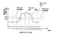
図5では、図4と同様に、各ボタンのサンプリングタイミングにおける平滑出力値を、ボタン1:○、ボタン2:□、ボタン3:△、ボタン4:×で表している。図5のように、本発明のスキャン方法では、時刻6でボタン1の真値が変化を始めたとき、次のサンプリングタイミング(時刻8)でサンプリング値の変化量が変化量閾値を超えたことを検知でき、ボタン1の次のサンプリングタイミングは、図4のような時刻12ではなく、本来はボタン2のサンプリングタイミングである時刻9となる。時刻9で算出した平滑出力値がボタンON判定閾値を上回ったので、従来のスキャン方法の時刻12よりも早い時点で、ユーザ14がボタン1を押下したこと(すなわち、ユーザ14の手指の接近,ボタンON)を検出できる。 In FIG. 5, as in FIG. 4, the smoothed output values at the sampling timing of each button are represented by button 1: ○, button 2: □, button 3: Δ, and button 4: ×. As shown in FIG. 5, in the scanning method of the present invention, when the true value of the button 1 started to change at
さらに、時刻9でサンプリング値の変化量が変化量閾値を超えると、さらに、本来はボタン3のサンプリングタイミングである時刻10でも、ボタン1のサンプリングを実行する。そして、サンプリング回数カウンタ値がカウンタ閾値(図5の例では2)を上回ると、次のサンプリングタイミングである時刻11では、ボタン2のサンプリングを実施する。以降は、上述した通常のサンプリング順に、各ボタンのサンプリングを実行する。 Further, when the change amount of the sampling value exceeds the change amount threshold value at
また、ユーザ14がボタンから手指を離したこと(ボタンOFF)も、従来技術の方法に比べて早く検出できる。すなわち、静電容量のサンプリング値のマイナス変化量(これを絶対値で算出)について、変化量閾値を越えた場合、前述のボタンONの場合と同様な方法でスキャンを行えばよい。真値が時刻18で変化を開始したとき、図4のように、従来技術の方法では、時刻24でボタンOFFを検出している。一方、本発明の方法(図5)では、それよりも早い時刻20でボタンOFFを検出することができる。 Further, the fact that the
上述の構成では、変化があったボタンを連続してスキャンするものであるが、他のボタン1個をスキャンした次に変化があったボタンを1回スキャンして、スキャン優先度を上げる方法がある。すなわち、ボタン1→ボタン2→ボタン1→ボタン3→ボタン1→ボタン4のようにスキャンする。以下、図8を用いて、本構成におけるスイッチ入力処理について説明する。なお、本処理は、図7の構成に処理の追加を行ったものであるため、ボタン1を例に挙げ、追加分のみを説明し、図7と同様の処理ステップについては説明を割愛する。 In the above-described configuration, the changed button is continuously scanned. However, there is a method of raising the scan priority by scanning the changed button once after the other button is scanned. is there. That is, scanning is performed as button 1 → button 2 → button 1 →
まず、切替スイッチ5でボタン1を選択し(S101)、ボタン1に電圧Vcを印加して、サンプリングタイミングが到来したとき(S102:Yes)、ボタン1の状態をサンプリングして、今回のサンプリング値を取得する。次に、今回のサンプリング値を用いて平滑出力値を算出する(S104)。さらに、ボタン1入力判定を行い(S105)、今回のサンプリング値と前回のサンプリング値との差である変化量を算出する(S106)。 First, the button 1 is selected with the changeover switch 5 (S101), the voltage Vc is applied to the button 1, and when the sampling timing comes (S102: Yes), the state of the button 1 is sampled, and the current sampling value To get. Next, a smooth output value is calculated using the current sampling value (S104). Further, a button 1 input determination is performed (S105), and a change amount which is a difference between the current sampling value and the previous sampling value is calculated (S106).
次に、算出した変化量が変化量閾値を上回るか否かを判定し、変化量が変化量閾値を上回るとき(S107:Yes)、ボタン1に対応する平滑出力値算出用カウンタ値あるいはサンプリング回数カウンタ値を参照し、このカウンタ値がカウンタ閾値を下回るか否かを判定する(S108)。カウンタ値がカウンタ閾値を下回るとき(S109:Yes)、カウンタ値を更新(インクリメント)し(S110)、メモリ10aあるいはRAM(図示せず)に記憶された、ボタン1に対応する優先スキャンフラグをセットする(S112)。 Next, it is determined whether or not the calculated change amount exceeds the change amount threshold value, and when the change amount exceeds the change amount threshold value (S107: Yes), the smoothed output value calculation counter value corresponding to the button 1 or the number of sampling times With reference to the counter value, it is determined whether or not the counter value is below the counter threshold value (S108). When the counter value falls below the counter threshold (S109: Yes), the counter value is updated (incremented) (S110), and the priority scan flag corresponding to the button 1 stored in the memory 10a or RAM (not shown) is set. (S112).
一方、変化量が変化量閾値を下回るとき(S107:No)、あるいは、カウンタ値がカウンタ閾値を上回るとき(S109:No)、カウンタ値をクリアし(S111)、ボタン1に対応する優先スキャンフラグをクリアする(S113)。 On the other hand, when the change amount falls below the change amount threshold value (S107: No), or when the counter value exceeds the counter threshold value (S109: No), the counter value is cleared (S111), and the priority scan flag corresponding to the button 1 Is cleared (S113).
次に、優先ボタン処理(S160)を実行する。まず、他のボタン(ボタン2〜4)に対応する優先スキャンフラグを参照し、いずれかの優先スキャンフラグがセットされているとき(S161:Yes)、その優先スキャンフラグに対応するボタンのスキャン処理を行う(S162)。この処理は、本処理のボタンスキャン処理(すなわち、ステップS101〜S113)に相当する。続いて、該当するボタンのボタン入力判定処理(S163,内容はS105と同様)を実行する。その後、ボタン2スキャン・入力判定処理(S200),および優先ボタン処理(S260,内容はステップS160と同様)を実行する。ステップS260の優先ボタン処理では、ボタン1に対応する優先スキャンフラグがセットされているときには、ボタン1のスキャンおよび入力判定を行う。 Next, priority button processing (S160) is executed. First, a priority scan flag corresponding to another button (buttons 2 to 4) is referred to, and when any of the priority scan flags is set (S161: Yes), the scan processing of the button corresponding to the priority scan flag (S162). This process corresponds to the button scan process (that is, steps S101 to S113) of this process. Subsequently, a button input determination process (S163, contents are the same as S105) of the corresponding button is executed. Thereafter, button 2 scan / input determination processing (S200) and priority button processing (S260, contents are the same as step S160) are executed. In the priority button process in step S260, when the priority scan flag corresponding to the button 1 is set, the button 1 is scanned and input is determined.
以降、同様に、ボタン3,4についても、ボタンスキャン・入力判定処理,および優先ボタン処理を実行する。 Thereafter, similarly, button scan / input determination processing and priority button processing are executed for the
静電スイッチ、静電タッチパネルなど、静電容量を利用したHMIに用いるスイッチやダイヤル(人体と電極間の静電容量、電極間の静電容量を利用したもの)以外にも、周知のメカニカルスイッチ、画面上に縦横に微細に赤外線センサを配置しておき、指やタッチペンなどでその赤外線を遮断すると、その遮断した位置を2次元座標値(X,Y)として検出する赤外線方式タッチパネル、あるいは抵抗膜方式のタッチパネル等、入力を順次スキャンする方式でスキャンに時間を要するものにも適用可能である。 In addition to switches and dials (capacitance between human body and electrodes, and capacitance between electrodes) such as electrostatic switches and electrostatic touch panels used for HMI using capacitance, well-known mechanical switches Infrared touch panel that detects the position of the infrared sensor as a two-dimensional coordinate value (X, Y) when the infrared sensor is finely arranged vertically and horizontally on the screen and the infrared ray is blocked with a finger or a touch pen. The present invention can also be applied to a film type touch panel or the like that sequentially scans inputs and requires time for scanning.
以上、本発明の実施の形態を説明したが、これらはあくまで例示にすぎず、本発明はこれらに限定されるものではなく、特許請求の範囲の趣旨を逸脱しない限りにおいて、当業者の知識に基づく種々の変更が可能である。 Although the embodiments of the present invention have been described above, these are merely examples, and the present invention is not limited to these embodiments, and the knowledge of those skilled in the art can be used without departing from the spirit of the claims. Various modifications based on this are possible.
1〜4 ボタン(スイッチ,静電容量検出電極,検出電極)
5 切替スイッチ(入力信号選択部)
10 CPU(サンプリング部,変化量算出部,平滑出力値演算部,サンプリング回数計測部,演算回数計測部)
11 電源
100 入力信号処理装置
SW1、SW2 電荷移動用スイッチ
Ci 電荷積分用コンデンサ(コンデンサ)
Rb 放電抵抗
SW3 放電用スイッチ1-4 buttons (switch, capacitance detection electrode, detection electrode)
5 changeover switch (input signal selector)
10 CPU (sampling unit, variation calculation unit, smooth output value calculation unit, sampling count measurement unit, calculation count measurement unit)
11
Rb Discharge resistor SW3 Discharge switch
Claims (7)
Translated fromJapanese前記入力信号選択部が出力した入力信号の状態をサンプリングするサンプリング部と、
前記サンプリングの結果に基づいて、前記入力信号の変化量を算出する変化量算出部と、
を備え、
前記入力信号選択部は、前記変化量算出部が算出した前記入力信号の変化量が予め定められた変化量閾値を超えるとき、前記変化量閾値を超えた入力信号の出力を継続することを特徴とする入力信号処理装置。An input signal selection unit that receives a plurality of input signals, selects one of the plurality of input signals based on a predetermined selection order, and outputs the selected input signal;
A sampling unit for sampling the state of the input signal output by the input signal selection unit;
A change amount calculation unit that calculates a change amount of the input signal based on the sampling result;
With
The input signal selection unit continues output of an input signal exceeding the change amount threshold when the change amount of the input signal calculated by the change amount calculation unit exceeds a predetermined change amount threshold value. An input signal processing device.
前記サンプリング回数計測部による計測回数が予め定められた回数に達したとき、前記優先出力停止条件が成立したとする請求項2または請求項3に記載の入力信号処理装置。A sampling number measuring unit for measuring the number of times of sampling;
The input signal processing device according to claim 2, wherein the priority output stop condition is satisfied when the number of times of measurement by the sampling number measuring unit reaches a predetermined number of times.
前記平滑出力値演算部の演算回数を計測する演算回数計測部と、
を備え、
前記平滑出力値演算部による演算回数が予め定められた回数に達したとき、前記優先出力停止条件が成立したとする請求項2ないし請求項4のいずれか1項に記載の入力信号処理装置。Based on the sampling result, a smooth output value calculation unit that smoothes the input signal and calculates a smooth output value;
A calculation number measuring unit for measuring the number of calculations of the smoothed output value calculating unit;
With
5. The input signal processing device according to claim 2, wherein the priority output stop condition is satisfied when the number of calculations by the smoothed output value calculation unit reaches a predetermined number. 6.
Priority Applications (1)
| Application Number | Priority Date | Filing Date | Title |
|---|---|---|---|
| JP2011063698AJP5557165B2 (en) | 2011-03-23 | 2011-03-23 | Input signal processor |
Applications Claiming Priority (1)
| Application Number | Priority Date | Filing Date | Title |
|---|---|---|---|
| JP2011063698AJP5557165B2 (en) | 2011-03-23 | 2011-03-23 | Input signal processor |
Publications (2)
| Publication Number | Publication Date |
|---|---|
| JP2012199852Atrue JP2012199852A (en) | 2012-10-18 |
| JP5557165B2 JP5557165B2 (en) | 2014-07-23 |
Family
ID=47181616
Family Applications (1)
| Application Number | Title | Priority Date | Filing Date |
|---|---|---|---|
| JP2011063698AExpired - Fee RelatedJP5557165B2 (en) | 2011-03-23 | 2011-03-23 | Input signal processor |
Country Status (1)
| Country | Link |
|---|---|
| JP (1) | JP5557165B2 (en) |
Cited By (4)
| Publication number | Priority date | Publication date | Assignee | Title |
|---|---|---|---|---|
| JP2018160110A (en)* | 2017-03-23 | 2018-10-11 | 東プレ株式会社 | Capacitive keyboard device |
| CN110908520A (en)* | 2018-09-14 | 2020-03-24 | 东普雷股份有限公司 | Electrostatic capacitance type keyboard |
| US10676118B2 (en) | 2016-10-28 | 2020-06-09 | Honda Motor Co., Ltd. | Steering wheel unit |
| TWI780222B (en)* | 2018-09-07 | 2022-10-11 | 日商東普雷股份有限公司 | Electrostatic capacitive keyboard device |
Citations (2)
| Publication number | Priority date | Publication date | Assignee | Title |
|---|---|---|---|---|
| JPH0644470A (en)* | 1992-07-24 | 1994-02-18 | Ibiden Co Ltd | Security system |
| JP2010152876A (en)* | 2008-11-26 | 2010-07-08 | Seiko Instruments Inc | Electrostatic capacitance detection device, electrostatic capacitance detection circuit, electrostatic capacitance detection method and initialization method |
- 2011
- 2011-03-23JPJP2011063698Apatent/JP5557165B2/ennot_activeExpired - Fee Related
Patent Citations (2)
| Publication number | Priority date | Publication date | Assignee | Title |
|---|---|---|---|---|
| JPH0644470A (en)* | 1992-07-24 | 1994-02-18 | Ibiden Co Ltd | Security system |
| JP2010152876A (en)* | 2008-11-26 | 2010-07-08 | Seiko Instruments Inc | Electrostatic capacitance detection device, electrostatic capacitance detection circuit, electrostatic capacitance detection method and initialization method |
Cited By (5)
| Publication number | Priority date | Publication date | Assignee | Title |
|---|---|---|---|---|
| US10676118B2 (en) | 2016-10-28 | 2020-06-09 | Honda Motor Co., Ltd. | Steering wheel unit |
| JP2018160110A (en)* | 2017-03-23 | 2018-10-11 | 東プレ株式会社 | Capacitive keyboard device |
| TWI780222B (en)* | 2018-09-07 | 2022-10-11 | 日商東普雷股份有限公司 | Electrostatic capacitive keyboard device |
| CN110908520A (en)* | 2018-09-14 | 2020-03-24 | 东普雷股份有限公司 | Electrostatic capacitance type keyboard |
| CN110908520B (en)* | 2018-09-14 | 2024-02-09 | 东普雷股份有限公司 | Electrostatic capacitive keyboard |
Also Published As
| Publication number | Publication date |
|---|---|
| JP5557165B2 (en) | 2014-07-23 |
Similar Documents
| Publication | Publication Date | Title |
|---|---|---|
| Lin et al. | Position estimation and smooth tracking with a fuzzy-logic-based adaptive strong tracking Kalman filter for capacitive touch panels | |
| EP3543716B1 (en) | Capacitance detection circuit, touch apparatus, and terminal device | |
| TWI474242B (en) | Touch panel | |
| CN100377055C (en) | Interpretation method of touch control induction device | |
| CN102006045B (en) | Method for judging capacitive touch keys | |
| JP5557165B2 (en) | Input signal processor | |
| KR20100109935A (en) | Time-sloped capacitance measuring circuits and methods | |
| JPWO2018193711A1 (en) | Touch sensor type electronic device and sensor control method | |
| EP2460064A1 (en) | Dynamic mode switching for fast touch response | |
| CN102084593A (en) | Capacitive voltage divider touch sensor | |
| CN102929422A (en) | Force sensing capacitive hybrid touch sensor | |
| EP2766992B1 (en) | Method for adapting the sensitivity of a sensor system | |
| CN101414819A (en) | Current source control and compensation touch control capacitance sensing method and device | |
| CN105630232B (en) | The control method and program of input unit, input unit | |
| US20140333581A1 (en) | Capacitive proximity detection system and method | |
| US20110169768A1 (en) | Electrostatic detection device, information apparatus, and electrostatic detection method | |
| CN103324365A (en) | Capacitive touch system, touch device and touch method | |
| CN101963865A (en) | Touch identification method, touch key structure and touch device | |
| CN107608863A (en) | The calibration method and mobile terminal that a kind of electricity is shown | |
| US8866490B1 (en) | Method and apparatus for eliminating tail effect in touch applications | |
| CN108512542A (en) | Touch key-press signal processing method and device, computer readable storage medium | |
| CN110568502A (en) | Liquid detection method and controller on capacitive touch panel | |
| US8421765B2 (en) | Touch sensing device and method | |
| JP2018060502A (en) | Input device | |
| US20060142970A1 (en) | Slide pad system and method |
Legal Events
| Date | Code | Title | Description |
|---|---|---|---|
| RD02 | Notification of acceptance of power of attorney | Free format text:JAPANESE INTERMEDIATE CODE: A7422 Effective date:20121016 | |
| A621 | Written request for application examination | Free format text:JAPANESE INTERMEDIATE CODE: A621 Effective date:20130524 | |
| A977 | Report on retrieval | Free format text:JAPANESE INTERMEDIATE CODE: A971007 Effective date:20140124 | |
| A131 | Notification of reasons for refusal | Free format text:JAPANESE INTERMEDIATE CODE: A131 Effective date:20140128 | |
| A521 | Written amendment | Free format text:JAPANESE INTERMEDIATE CODE: A523 Effective date:20140326 | |
| TRDD | Decision of grant or rejection written | ||
| A01 | Written decision to grant a patent or to grant a registration (utility model) | Free format text:JAPANESE INTERMEDIATE CODE: A01 Effective date:20140512 | |
| R151 | Written notification of patent or utility model registration | Ref document number:5557165 Country of ref document:JP Free format text:JAPANESE INTERMEDIATE CODE: R151 | |
| A61 | First payment of annual fees (during grant procedure) | Free format text:JAPANESE INTERMEDIATE CODE: A61 Effective date:20140525 | |
| R250 | Receipt of annual fees | Free format text:JAPANESE INTERMEDIATE CODE: R250 | |
| R250 | Receipt of annual fees | Free format text:JAPANESE INTERMEDIATE CODE: R250 | |
| R250 | Receipt of annual fees | Free format text:JAPANESE INTERMEDIATE CODE: R250 | |
| R250 | Receipt of annual fees | Free format text:JAPANESE INTERMEDIATE CODE: R250 | |
| LAPS | Cancellation because of no payment of annual fees |