JP2012199599A - Cordless phone - Google Patents
Cordless phoneDownload PDFInfo
- Publication number
- JP2012199599A JP2012199599AJP2009183009AJP2009183009AJP2012199599AJP 2012199599 AJP2012199599 AJP 2012199599AJP 2009183009 AJP2009183009 AJP 2009183009AJP 2009183009 AJP2009183009 AJP 2009183009AJP 2012199599 AJP2012199599 AJP 2012199599A
- Authority
- JP
- Japan
- Prior art keywords
- unit
- cordless
- power supply
- power
- charging
- Prior art date
- Legal status (The legal status is an assumption and is not a legal conclusion. Google has not performed a legal analysis and makes no representation as to the accuracy of the status listed.)
- Pending
Links
Images


Classifications
- H—ELECTRICITY
- H04—ELECTRIC COMMUNICATION TECHNIQUE
- H04M—TELEPHONIC COMMUNICATION
- H04M1/00—Substation equipment, e.g. for use by subscribers
- H04M1/72—Mobile telephones; Cordless telephones, i.e. devices for establishing wireless links to base stations without route selection
- H04M1/725—Cordless telephones
- H04M1/72502—Cordless telephones with one base station connected to a single line
- H—ELECTRICITY
- H04—ELECTRIC COMMUNICATION TECHNIQUE
- H04M—TELEPHONIC COMMUNICATION
- H04M1/00—Substation equipment, e.g. for use by subscribers
- H04M1/72—Mobile telephones; Cordless telephones, i.e. devices for establishing wireless links to base stations without route selection
- H04M1/725—Cordless telephones
- H04M1/73—Battery saving arrangements
- H—ELECTRICITY
- H04—ELECTRIC COMMUNICATION TECHNIQUE
- H04W—WIRELESS COMMUNICATION NETWORKS
- H04W52/00—Power management, e.g. Transmission Power Control [TPC] or power classes
- H04W52/04—Transmission power control [TPC]
- H04W52/18—TPC being performed according to specific parameters
- H04W52/24—TPC being performed according to specific parameters using SIR [Signal to Interference Ratio] or other wireless path parameters
- H04W52/245—TPC being performed according to specific parameters using SIR [Signal to Interference Ratio] or other wireless path parameters taking into account received signal strength
- H—ELECTRICITY
- H04—ELECTRIC COMMUNICATION TECHNIQUE
- H04W—WIRELESS COMMUNICATION NETWORKS
- H04W52/00—Power management, e.g. Transmission Power Control [TPC] or power classes
- H04W52/02—Power saving arrangements
- H04W52/0209—Power saving arrangements in terminal devices
- H04W52/0225—Power saving arrangements in terminal devices using monitoring of external events, e.g. the presence of a signal
- H04W52/0245—Power saving arrangements in terminal devices using monitoring of external events, e.g. the presence of a signal according to signal strength
- Y—GENERAL TAGGING OF NEW TECHNOLOGICAL DEVELOPMENTS; GENERAL TAGGING OF CROSS-SECTIONAL TECHNOLOGIES SPANNING OVER SEVERAL SECTIONS OF THE IPC; TECHNICAL SUBJECTS COVERED BY FORMER USPC CROSS-REFERENCE ART COLLECTIONS [XRACs] AND DIGESTS
- Y02—TECHNOLOGIES OR APPLICATIONS FOR MITIGATION OR ADAPTATION AGAINST CLIMATE CHANGE
- Y02D—CLIMATE CHANGE MITIGATION TECHNOLOGIES IN INFORMATION AND COMMUNICATION TECHNOLOGIES [ICT], I.E. INFORMATION AND COMMUNICATION TECHNOLOGIES AIMING AT THE REDUCTION OF THEIR OWN ENERGY USE
- Y02D30/00—Reducing energy consumption in communication networks
- Y02D30/70—Reducing energy consumption in communication networks in wireless communication networks
Landscapes
- Engineering & Computer Science (AREA)
- Computer Networks & Wireless Communication (AREA)
- Signal Processing (AREA)
- Telephone Function (AREA)
- Mobile Radio Communication Systems (AREA)
- Telephone Set Structure (AREA)
- Charge And Discharge Circuits For Batteries Or The Like (AREA)
Abstract
Translated fromJapaneseDescription
Translated fromJapanese本発明は、2次電池から電源が供給されるコードレス子機と、電灯線から電源が供給される親機とを備えたコードレス電話機に関するものである。 The present invention relates to a cordless telephone including a cordless slave unit to which power is supplied from a secondary battery and a master unit to which power is supplied from a power line.
コードレス電話機は、コードレス子機を持ち、電話回線に接続された親機から離れて通話相手と会話ができるので、利便性が高い。しかし、停電時では、親機は、電灯線から電源が得られなくなり、コードレス子機との通信ができなくなることで、通話ができなくなる。 A cordless telephone has a cordless cordless handset, and is highly convenient because it can talk with a calling party away from the base unit connected to the telephone line. However, in the event of a power failure, the base unit cannot obtain power from the power line and cannot communicate with the cordless handset, making it impossible to make a call.
そこで、停電時でも通話ができるコードレス電話機が開発されている。例えば、特許文献1には、コードレス子機が親機との無線リンクが途絶したことを検出すると、コードレス子機の切替回路を切り替えてバッテリからの電流をバックアップ電流として親機へ通電することで、停電時でも親機とコードレス子機との間で通信できるようにしたコードレス電話機が記載されている。 Therefore, cordless telephones have been developed that can talk even during power outages. For example, in
しかし、特許文献1に記載のコードレス電話機では、コードレス子機に搭載した2次電池により当該コードレス子機と親機の両方を動作させているため、停電中は消費電流が増大し、通話時間が非常に短いことが懸念される。 However, in the cordless telephone set forth in
そこで本発明は、停電中の子機内電池の消耗を抑えることで、会話できる時間を長くすることができるコードレス電話機を提供することを目的とする。 SUMMARY OF THE INVENTION An object of the present invention is to provide a cordless telephone that can extend the conversation time by suppressing the consumption of the battery in the slave unit during a power failure.
本発明は、コードレス子機と、親機との間で無線通信を行うコードレス電話機において、親機への外部からの電力供給が停止したときに、コードレス子機が受信した親機の無線信号の信号強度に応じて、親機がコードレス子機へ送信する無線信号の送信電力を通信エラーが発生しないレベルまで低下させる省電力送信モードを設けた。 In the cordless telephone that performs wireless communication between the cordless slave unit and the master unit, the present invention provides a radio signal of the master unit received by the cordless slave unit when the external power supply to the master unit is stopped. A power saving transmission mode is provided in which the transmission power of the radio signal transmitted from the master unit to the cordless slave unit is reduced to a level at which no communication error occurs according to the signal strength.
また親機が複数台のコードレス子機と通信可能は場合において、親機の外部からの電力供給が停止したときに親機から各コードレス子機へ電力供給停止を示す情報を伝達し、該情報を受信した各コードレス子機は電力供給停止を示す情報を表示部に表示するようにした。 Also, when the master unit can communicate with a plurality of cordless slave units, when the power supply from the outside of the master unit is stopped, information indicating the power supply stop is transmitted from the master unit to each cordless slave unit. Each cordless cordless handset that has received the message displays information indicating that the power supply has been stopped on the display unit.
電力供給停止の時、親機と通信可能な複数のコードレス子機の中の1台を親機の充電部に載置すれば、他のコードレス子機は親機から離した状態でも通話可能となる。ことを特徴とする。 If one of the cordless slaves that can communicate with the master unit is placed on the charger of the master unit when the power supply is stopped, the other cordless slave units can talk even when they are separated from the master unit. Become. It is characterized by that.
本発明のコードレス電話機は、外部電力供給停止の時に親機の送信電力を調整することで親機側での電力消費を極力抑えることができるので、停電中でも会話できる時間を長くすることができる。また電力供給停止の時、親機と通信可能な複数のコードレス子機の中の1台を親機の充電部に載置すれば、この親機に載置されたコードレス子機の電池は主に親機が動作するための電力を賄えば良く、該コードレス子機は通話のための送信動作をする必要がないので電力消費を抑え、会話できる時間を長くすることができるとともに、他のコードレス子機を親機から離した状態で通話することが可能であり、コードレス電話機としての利便性が保たれる。 The cordless telephone according to the present invention can suppress the power consumption on the base unit side by adjusting the transmission power of the base unit when external power supply is stopped, so that it is possible to lengthen the time for conversation even during a power failure. If one of the cordless slaves that can communicate with the master unit is placed on the charging unit of the master unit when the power supply is stopped, the battery of the cordless slave unit placed on the master unit is the main battery. The cordless slave unit does not need to perform a transmission operation for a telephone call, so it can reduce power consumption, extend the time for conversation, and other cordless It is possible to make a call while the slave unit is separated from the master unit, and the convenience as a cordless telephone is maintained.
本願の第1の発明は、コードレス子機と、親機との間で無線通信を行うコードレス電話機において、親機は、外部電源から電力を基に親機内の各部に適正な電圧で電力を供給するための電源回路と、電源回路からの電力で動作可能な第1の制御部および第1の無線通信部と、コードレス子機が充電部に載置された場合に、コードレス子機側の端子と接触可能な第1の端子と、第1の端子を介してコードレス子機内の2次電池を充電するための充電電流を供給する充電回路とを有し、コードレス子機は、親機の充電部に載置されたときに、第1の端子と接触する第2の端子と、第1の端子および第2の端子を介して充電回路から送られる充電電流により充電される2次電池と、2次電池からの電力により動作可能な第2の制御部および第2の無線通信部とを有し、さらに親機は、外部からの電力供給があるときには遮断し、外部からの電力供給が停止したときには導通することにより、第1および第2の端子を介してコードレス子機から供給される電力を、第1の制御部および第1の無線通信部へ供給するためのスイッチ回路を有し、前記親機の第1の制御部は、外部からの電力供給が停止したときに、前記コードレス子機からの無線電波情報であって、前記コードレス子機の第2の無線通信部が受信した前記親機の第1の無線通信部からの無線信号の受信信号強度を示す無線電波情報に応じて、前記第1の無線通信部の送信電力を、通信エラーが発生しないレベルまで低下させる省電力送信モードに切り替えるよう前記第1の無線通信部に指示することを特徴としたコードレス電話機である。 1st invention of this application is a cordless telephone which performs radio | wireless communication between a cordless subunit | mobile_unit and a main | base station, A main | base station supplies electric power with an appropriate voltage to each part in a main | base station based on electric power from an external power supply. When the cordless slave unit is placed on the charging unit, the first control unit and the first wireless communication unit operable with power from the power source circuit, and the cordless slave unit side terminal And a charging circuit for supplying a charging current for charging a secondary battery in the cordless slave unit via the first terminal, the cordless slave unit charging the master unit A second battery that is in contact with the first terminal when mounted on the unit, a secondary battery that is charged by a charging current sent from the charging circuit via the first terminal and the second terminal, A second control unit operable by power from the secondary battery and a second non-operating unit; The cordless slave unit via the first and second terminals by shutting off when there is external power supply and conducting when the external power supply is stopped. When the power supply from the outside stops, the first control unit of the master unit has a switch circuit for supplying the power supplied from the first control unit and the first wireless communication unit And wireless radio wave information from the cordless slave unit, the radio signal indicating the received signal strength of the radio signal from the first radio communication unit of the master unit received by the second radio communication unit of the cordless slave unit A cordless system that instructs the first wireless communication unit to switch to a power-saving transmission mode that reduces the transmission power of the first wireless communication unit to a level at which no communication error occurs according to radio wave information. phone It is.
第1の発明によれば、外部からの電力供給が停止したときに、親機は省電力送信の動作に切り替わり、コードレス子機から送信される親機からの無線信号の受信信号強度を示す無線電波情報に応じて、コードレス子機への無線信号の送信電力を、通信エラーが発生しないレベルまで低下させるので、親機側での電力消費を極力抑え、比較的長時間の音声通話を続けることができる。 According to the first invention, when the external power supply is stopped, the parent device switches to the power saving transmission operation, and the wireless signal indicating the received signal strength of the wireless signal transmitted from the cordless child device is transmitted. Depending on the radio wave information, the transmission power of the wireless signal to the cordless slave unit is reduced to a level where no communication error occurs, so the power consumption on the base unit side is suppressed as much as possible and the voice call for a relatively long time is continued. Can do.
本願の第2の発明は、第1の発明において、前記コードレス子機の第2の制御部は、
ハンドフリー通話機能を有し、親機から外部電力供給停止を示す情報が伝達され、かつ親機の充電部に載置された場合に、通話動作開始を示す情報が伝達されるとハンドフリー通話機能を起動することを特徴としたコードレス電話機である。According to a second aspect of the present invention, in the first aspect, the second control unit of the cordless handset is
A hand-free call function that has a hand-free call function and when the information indicating the stop of external power supply is transmitted from the master unit and the information indicating the start of the call operation is transmitted when placed on the charging unit of the master unit. A cordless telephone characterized by activating a function.
本願の第2の発明によれば、コードレス子機を親機の充電部に載置した状態で着信があった場合、使用者は特別にハンドフリー通話機能を起動する操作をすることなく、自動的にハンドフリー通話が開始されることになり、コードレス子機を親機に載置した状態での通話にはいることができる。 According to the second invention of the present application, when there is an incoming call in a state where the cordless slave unit is placed on the charging unit of the master unit, the user does not need to perform a special operation to activate the hands-free call function. Thus, a hands-free call is started, and it is possible to enter a call in a state where the cordless child device is placed on the parent device.
本願の第3の発明は、第1の発明において、親機の第1の制御部は、外部からの電力供給が停止したときに、第1の無線通信部を介してコードレス子機へ電力供給停止を示す情報を伝達し、コードレス子機は、第2の制御部により制御される表示部を有し、コードレス子機の第2の制御部は、親機からの電力供給停止を示す情報を、第2の無線通信部を介して受信すると、親機に対する外部からの電力供給が停止した状態であることを表示部に表示することを特徴したコードレス電話機である。 According to a third invention of the present application, in the first invention, the first control unit of the master unit supplies power to the cordless slave unit via the first wireless communication unit when the external power supply is stopped. The cordless slave unit has a display unit controlled by the second control unit, and the second control unit of the cordless slave unit transmits information indicating the power supply stop from the master unit. The cordless telephone is characterized in that when it is received via the second wireless communication unit, the display unit displays that the external power supply to the base unit is stopped.
第3の発明によれば、外部からの電力供給が停止したとき、コードレス子機の使用者に電源の異常を知らせたり、親機への充電部への載置を促すことができる。 According to the third aspect, when the external power supply is stopped, it is possible to notify the user of the cordless slave unit of the abnormality of the power source or to prompt the user to place the cordless slave unit on the charging unit.
本願の第4の発明は、第1の発明において、親機は、外部からの電力またはコードレス子機内の2次電池からの電力で受電され、第1の制御部および第1の無線通信部の動作を持続可能にする大容量のキャパシタを有することを特徴としたコードレス電話機である。 According to a fourth invention of the present application, in the first invention, the master unit receives power from the outside or power from the secondary battery in the cordless slave unit, and the first control unit and the first wireless communication unit A cordless telephone characterized by having a large-capacitance capacitor capable of sustaining operation.
第4の発明によれば、コードレス子機が親機から離された状態で、親機への外部電力の供給が停止された場合や、または外部電力停止状態でコードレス子機内の電池で親機が動作し、その状態でコードレス子機が親機から取り外された場合でも、しばらくの間は大容量のキャパシタにより親機の動作は維持されるので、通話が突然切れることが無く、コードレス子機と親機を離した状態での通話を維持することができる。 According to the fourth invention, when the supply of external power to the master unit is stopped in a state where the cordless slave unit is separated from the master unit, or the battery in the cordless slave unit is stopped in the external power stop state. Even if the cordless cordless handset is removed from the base unit in that state, the operation of the base unit is maintained for a while by the large-capacity capacitor. It is possible to maintain a call in a state where the main unit is separated.
本願の第5の発明は、コードレス子機と、親機との間で無線通信を行うコードレス電話機において、親機は、外部電源から電力を基に親機内の各部に適正な電圧で電力を供給するための電源回路と、電源回路からの電力で動作可能な第1の制御部および第1の無線通信部と、コードレス子機が充電部に載置された場合に、コードレス子機側の端子と接触可能な第1の端子と、第1の端子を介してコードレス子機内の2次電池を充電するための充電電流を供給する充電回路とを有し、コードレス子機は、親機側の第1の端子と接触可能な第2の端子と、第1の端子および第2の端子を介して充電回路から送られる充電電流により充電される2次電池と、2次電池からの電力により動作可能な第2の制御部および第2の無線通信部と、第2の制御部により制御される表示部とを有し、さらに親機は、充電回路の出力電圧が低下した場合に、コードレス子機内の2次電池より第1の端子および第2の端子を介して逆流する電流が充電回路へ流れ込まない様に遮断するための逆流防止回路と、外部からの電力供給があるときには遮断し、外部からの電力供給が停止したときには導通することにより、第1および第2の端子を介してコードレス子機から供給される電力を第1の制御部および第1の無線通信部へ供給するためのスイッチ回路とを有し、親機の第1の制御部は、外部からの電力供給が停止したときに、第1の無線通信部を介して通信可能な全てのコードレス子機へ電力供給停止を示す情報を伝達し、該情報を受信した各コードレス子機の第2の制御部は、電力供給停止を示す情報を表示部に表示し、親機と通信可能な全てのコードレス子機のうち第1のコードレス子機が、親機の充電部に載置されたときに、他のコードレス子機は、第1のコードレス子機内の2次電池により動作する親機と通信が可能であることを特徴としたコードレス電話機である。 According to a fifth aspect of the present invention, in the cordless telephone that performs wireless communication between the cordless slave unit and the master unit, the master unit supplies power at an appropriate voltage to each part in the master unit based on power from an external power source. When the cordless slave unit is placed on the charging unit, the first control unit and the first wireless communication unit operable with power from the power source circuit, and the cordless slave unit side terminal And a charging circuit for supplying a charging current for charging a secondary battery in the cordless slave unit via the first terminal. A second terminal that can contact the first terminal, a secondary battery that is charged by a charging current sent from the charging circuit via the first terminal and the second terminal, and an electric power from the secondary battery. Possible second control unit and second wireless communication unit, and second control And the base unit further includes a current that flows backward from the secondary battery in the cordless slave unit through the first terminal and the second terminal when the output voltage of the charging circuit decreases. The first and second terminals are connected by blocking a backflow prevention circuit for shutting off so as not to flow into the charging circuit and shutting off when there is an external power supply, and conducting when the external power supply is stopped. And a switch circuit for supplying power supplied from the cordless slave unit to the first control unit and the first wireless communication unit, and the first control unit of the master unit supplies power from the outside Is transmitted to all cordless slaves that can communicate via the first wireless communication unit, and the second control unit of each cordless slave that has received the information , Information indicating power supply stop When the first cordless slave unit is placed on the charging unit of the master unit among all cordless slave units that are displayed on the display unit and can communicate with the master unit, the other cordless slave units are The cordless telephone is characterized in that it can communicate with a base unit that is operated by a secondary battery in the cordless handset.
第5の発明によれば、電力供給停止の時、親機と通信可能な複数のコードレス子機の中の1台を親機の充電部に載置すれば、このコードレス子機の電池は主に親機が動作するための電力を賄えば良く、該コードレス子機は通話のために送信動作をする必要がないので電力消費を抑えることができる。また使用者は他のコードレス子機を親機から離した状態で使い、通話することができるので、コードレス電話機としての利便性が保たれる。 According to the fifth aspect of the present invention, when one of a plurality of cordless slaves that can communicate with the master unit is placed on the charging unit of the master unit when the power supply is stopped, the battery of the cordless slave unit is the main battery. The cordless slave unit does not need to perform a transmission operation for a telephone call, so that power consumption can be suppressed. In addition, the user can use other cordless handsets away from the base phone and make a call, so the convenience as a cordless telephone is maintained.
本願の第6の発明は、第1または第5の発明において、スイッチ回路はトランジスタ及び電界効果トランジスタなどの半導体素子から構成されるコードレス電話機である。 A sixth invention of the present application is the cordless telephone set according to the first or fifth invention, wherein the switch circuit is composed of a semiconductor element such as a transistor and a field effect transistor.
(実施の形態)
本発明の実施の形態に係るコードレス電話装置について、図面に基づいて説明する。(Embodiment)
A cordless telephone apparatus according to an embodiment of the present invention will be described with reference to the drawings.
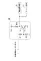
図1に示すコードレス電話機1は、電話回線に接続された親機2と、親機2と無線通信する2台のコードレス子機3(3x,3y)とを備えている。以下、コードレス子機を、単に子機と称する。図1では、一方のコードレス子機3xが親機2の充電部に載置され、他方のコードレス子機3yは他の充電台4に載置された状態を示す。 A
親機2は、電灯線に接続されるACアダプタ2aにより電源が供給される。子機3xは、親機2に搭載されることで電源が供給され、子機3xに実装された2次電池が充電される。子機3yは、充電台4に搭載されることで、電灯線に接続されるACアダプタ2aから電源が供給され、子機3yに実装された2次電池が充電される。 The
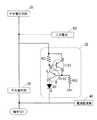
親機2は、図2に示すように、第1の制御部である電話部20と、第1の無線通信部である親無線部21と、電源回路22と、親定電圧回路23と、電圧検出回路24と、親充電回路25と、充電部26と、スイッチ回路27と、キャパシタ28と、スピーカ部29とを備えている。 As shown in FIG. 2, the
電話部20は、回線インタフェース部20aと、親電話制御部20bとを備えている。 The
回線インタフェース部20aは、電話回線と接続され、着信信号を検知すると共に、電話回線との音声アナログ信号と、親電話制御部20bとの音声デジタル信号とを相互変換する機能を有する。回線インタフェース部20aは、図3(b)に示すように、背面側の凹部2bに下方に向かって差し込み口が設けられた公衆回線接続コネクタ2cに電話ケーブルの一端を接続し、他端を壁面に設置されたモジュラージャックに接続することで、電話回線と接続される。 The line interface unit 20a is connected to a telephone line and has a function of detecting an incoming signal and mutually converting a voice analog signal from the telephone line and a voice digital signal from the parent telephone control unit 20b. As shown in FIG. 3B, the line interface unit 20a connects one end of a telephone cable to a public
図2に示す親電話制御部20bは、親機2全体を統括制御するもので、親無線部21を介して、音声デジタル信号を子機3と送受信したり、子機3へ停電情報を送信したり、親無線部21に対して送信電力の調整を行ったりするものである。親電話制御部20bは、プロセッサと、このプロセッサを動作させるための周辺回路とから形成されている。 A master telephone control unit 20b shown in FIG. 2 performs overall control of the
親無線部21は、親機2が主制御局、子機3が従局となって、TDMA(時分割多重)で通信するための変調および復調を行い、アンテナ21aを介して子機3と音声デジタル信号を送受信する。また、親無線部21は、親電話制御部20bからの指示により子機3への無線信号の送信電力を調整する機能を備えている。 The
電源回路22は、図3(b)に示す凹部2bに設けられた外部電源コネクタ2dに接続されるACアダプタ2aからの直流電圧を低圧して、適正な電圧で電力を供給するDC/DCコンバータである。本実施の形態では、電源回路22はACアダプタ2aからの直流6.5Vを直流2.5Vに変換するダウンコンバータである。 The
親定電圧回路23は、安定した直流電圧を電話部20および親無線部21へ供給する定電圧源で、電源回路22からの直流2.5Vを、さらに直流1.8Vに低圧するものである。 The master
電圧検出回路24は、ACアダプタ2aからの直流電圧が所定電圧以下となったことを検出すると、停電検知信号を有効とすることで、停電であることを親電話制御部20bおよびスイッチ回路27へ通知する。また、電圧検出回路24は、所定電圧以上にACアダプタ2aからの直流電圧が復帰したことを検出すると、停電検知信号を無効することで、復電したことを親電話制御部20bおよびスイッチ回路27へ通知する。 When the
ここで、電圧検出回路24の一例について、図5に基づいて詳細に説明する。本実施の形態では、電圧検出回路24は、外部電源コネクタ2dに接続された分割抵抗R11,R12と、ベースBが分割抵抗R11,R12の接続点に接続され、コレクタCが抵抗R13を介在させて電源Vccに接続され、エミッタEが接地されたトランジスタTr1とにより形成されている。このトランジスタTr1のコレクタCがスイッチ回路27に接続されていると共に、親電話制御部20bに接続されていることで、電圧検出回路24は、外部からの電力供給の有無を伝達する。 Here, an example of the
親充電回路25は、子機3に実装される2次電池BTを充電するための充電電流を出力する定電流源である。ここで、親充電回路25の一例について、図6に基づいて詳細に説明する。親充電回路25は、トランジスタTr21,22と、抵抗R21,R22と、ダイオードD1とにより形成されている。トランジスタTr21は、エミッタEが外部電源コネクタ2dと抵抗R21の一端とに接続され、ベースBが抵抗R21の他端とトランジスタTr22のエミッタEに接続され、コレクタCがトランジスタTr22のベースBと抵抗R22の一端に接続されている。トランジスタTr22は、コレクタCがダイオードD1のアノードAに接続されている。抵抗R22は、他端が接地されている。逆流防止回路として機能するダイオードD1のカソードKが、詳細には後述する充電部26の端子T11に接続されて、子機3からのバックアップ電流として流れる電流が、親充電回路25内に逆流することを防止している。 The
充電部26は、例えば図3(a)に示すように親機2上に形成された凹部2eであり、充電時はこの凹部2e内に子機3が載置される。この凹部2eの底部には、2つの端子T11,T12が設けられている。端子T11,T12は、子機3の2次電池へ充電電流を供給するための第1の端子である。端子T11は正極端子であり、端子T12は親機2のグランドと接続されている接地端子である。 The charging
スイッチ回路27は、電圧検出回路24からの停電検知信号が無効(非停電状態)であれば遮断状態とし、停電検知信号が有効(停電状態)であれば接続状態とするものである。ここで、スイッチ回路27の一例について、図7に基づいて詳細に説明する。スイッチ回路27は、トランジスタTr31,32と、抵抗R3,R4とから形成されている。トランジスタTr31は、ベースBがR4を介して電圧検出回路24に接続され、コレクタCが抵抗R3の一端に接続され、エミッタEが接地されている。トランジスタTr32は、ベースBが抵抗R3の他端に接続され、エミッタEが端子T11に接続され、コレクタCが親定電圧回路23に接続されている。 The
図2に示すキャパシタ28は、電源回路22からの充電電流や、子機3からのバックアップ電流により充電されるコンデンサである。本実施の形態では、キャパシタ28として容量が大きい電気二重層コンデンサを使用している。 A
スピーカ部29は、親電話制御部20bから出力された着呼を報知する音声を鳴動するためのアンプ付きのスピーカである。 The speaker unit 29 is a speaker with an amplifier for sounding a voice for notifying an incoming call output from the parent telephone control unit 20b.
次に、子機3について説明する。子機3は、端子T21,T22と、子充電回路30と、子定電圧回路31と、2次電池BTと、子定電流回路32と、第2の制御部である子電話制御部33と、スピーカ部34と、レシーバ部35と、マイク部36と、キーパッド部37と、表示部38と、第2の無線通信部である子無線部39と、電流監視部40とを備えている。 Next, the
図4に示すように、子機3の基端部に設けられた端子T21,T22は、子機3を親機2の充電部26に載置して端子T11,T12と接触させて充電電流を入力するための第2の端子である。充電部26である図3(a)に示す親機2の凹部2eに、子機3の底部を載置したときに、端子T11,T12と接触するように、子機3の端子T21,T22は、図4に示すように子機3の底部に設けられている。 As shown in FIG. 4, the terminals T21 and T22 provided at the base end of the
子充電回路30は、親機2や充電台4から供給される充電電流を入力して2次電池BTに供給する。子充電回路30は、例えば、図8に示すように、親充電回路25と同様の回路構成(図6参照)とすることができる。図8に示す子充電回路30は、トランジスタTr41,42と、抵抗R41,R42と、ダイオードD2とにより形成されている。トランジスタTr41は、エミッタEが端子T21と抵抗R41の一端とに接続され、ベースBが抵抗R41の他端とトランジスタTr42のエミッタEに接続され、コレクタCがトランジスタTr42のベースBと抵抗R42の一端に接続されている。トランジスタTr42は、コレクタCがダイオードD2のアノードAに接続されている。抵抗R42は、他端が接地されている。逆流防止回路として機能するダイオードD2のカソードKが、2次電池BTに接続されて、2次電池BTからのバックアップ電流が、子充電回路30内に逆流することを防止している。 The
子定電圧回路31は、安定した直流電圧を、子電話制御部33や、キーパッド部37、表示部38、子無線部39へ供給する定電圧源で、親機2の電源回路22からの直流2.5Vをさらに直流1.8Vに低圧するものである。 The child
子定電流回路32は、外部からの電力供給が停止したときに、2次電池BTからのバックアップ電流を親機2へ端子T21,T11を介して供給するためのものである。ここで、子定電流回路32の一例について、図9に基づいて説明する。 The child constant
図9に示す子定電流回路32は、親充電回路25と同様の回路構成(図6参照)とすることができる。子定電流回路32は、トランジスタTr51,52と、抵抗R51,R52と、ダイオードD3とにより形成されている。トランジスタTr51は、エミッタEが2次電池BTと抵抗R51の一端とに接続され、ベースBが抵抗R51の他端とトランジスタTr52のエミッタEに接続され、コレクタCがトランジスタTr52のベースBと抵抗R52の一端に接続されている。トランジスタTr52は、コレクタCがダイオードD3のアノードAに接続されている。抵抗R52は、他端が接地されている。逆流防止回路として機能するダイオードD3のカソードKが、端子T21に接続されて、親機2からの充電電流が、子定電流回路32内に逆流することを防止している。 The child constant
図2に示す子電話制御部33は、子機3全体を統括制御するもので、子無線部39を介して音声デジタル信号を親機2と送受信したり、親機2からの停電情報に応じて制御を行ったりするものである。また、子電話制御部33は、子無線部39により測定された親機2からの無線信号の受信信号強度を親機2へ通知する。 The slave
スピーカ部34は、図4に示すように、子機3の背面側に設けられ、ハンズフリー通話の際に、子電話制御部33からの音声信号をアンプにより増幅して音声として出力する。レシーバ部35は、子機3の先端部に設けられ、音声を再生するためのスピーカである。マイク部36は、音声を入力して音声信号として子電話制御部33へ出力する。キーパッド部37は、数字キーや記号キー、機能キーを備えた操作キー群である。このキーパッド部37の各キーは、光透過性の樹脂で形成され、内側にバックライトとして機能するLEDが設けられている。表示部38は、子電話制御部33の表示データに基づいて表示するLCDである。 As shown in FIG. 4, the
子無線部39は、親機2とTDMAで通信するための変調および復調を行い、アンテナ39aを介して音声デジタル信号を送受信する。また、子無線部39は、親機2からの無線信号の受信信号強度を測定して、子電話制御部33へ通知する。 The
電流監視部40は、子定電流回路32が親機2へ向けて2次電池BTからの電流を流しているか否かを監視し、通電状態を子電話制御部33へ通知する。 The
以上のように構成された本発明の実施の形態に係るコードレス電話装置の使用状態および動作を説明する。 The usage state and operation of the cordless telephone apparatus according to the embodiment of the present invention configured as described above will be described.
まず、非停電状態のときの通常の使用状態を説明する。外部からの電力供給が可能である場合には、ACアダプタ2aから直流電圧6.5Vが供給される。外部電源コネクタ2dから電源供給されていると、図5に示す電圧検出回路24では、分割抵抗R11,R12の接続点に分割比による電圧降下が発生する。従って、トランジスタTr1はオン状態となるため、コレクタCからエミッタEに電流が流れるので、コレクタCの出力(停電検知信号)は非停電状態(無効)を示すLレベルとなる。この停電検知信号の無効は、スイッチ回路27に通知されると共に、親電話制御部20bへ通知される。 First, the normal use state at the time of a non-power-out state is demonstrated. When power can be supplied from the outside, a DC voltage of 6.5 V is supplied from the
スイッチ回路27では、停電検知信号の無効を示すLレベルがトランジスタTr31のベースBに伝達されることで、トランジスタTr31がオフ状態となる。従って、トランジスタTr32もオフ状態である。 In the
ACアダプタ2aから直流6.5Vは、電源回路22へ供給される。電源回路22では、直流6.5Vが2.5Vへ変換される。そして親定電圧回路23により電話部20および親無線部21が動作するのに適正な1.8Vに変換される。また、ACアダプタ2aからの電流は、親充電回路25へ供給され、端子T11を介して子機3へ供給される。 A DC voltage of 6.5 V is supplied from the
子機3では、親機2の充電部26に設けられた端子T11と接触する端子T21から、電流が子充電回路30へ供給される。このとき、子定電流回路32にはダイオードD3が設けられており、端子T11,T21の電位が2次電池BT側の電位より高いため、子定電流回路32からの回り込み電流はない。 In the subunit |
子充電回路30からの電流は、充電電流となって2次電池BTを充電する充電電流となる。また、子充電回路30からの電流が子定電圧回路31へ供給されることで、子電話制御部33および子無線部39に対して子定電圧回路31により適正な電圧で電力が供給される。 The current from the
このようにして、コードレス電話機1では、非停電状態において外部の電源から各部へ電力が供給される。 In this way, in the
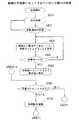
次に、停電状態における親機2の動作について、図10に基づいて説明する。この親機2には子機3xが充電部26に載置されているものとする。 Next, operation | movement of the main |
非停電状態であれば、外部電源であるACアダプタ2aから電源が供給されるので、親機2は子機3との通信を行ったり、電話回線からの着信待ちをするなどの通常処理を行っている(ステップS110)。 In the non-power failure state, power is supplied from the
停電が発生すると、ACアダプタ2aからの電圧が低下するので、親機2の電圧検出回路24では、分割抵抗R11,R12の接続点の電位が低下し、トランジスタTr11がオフ状態となるため、コレクタCの電位は電源電圧までプルアップされる。従って、コレクタCの出力(停電検知信号)は停電状態(有効)を示すHレベルとなる。この停電検知信号の有効は、スイッチ回路27に通知されると共に、親電話制御部20bへ通知される。また、ACアダプタ2aからの電圧低下により親充電回路25から子機3xへ電流が流れなくなる。停電が発生していないときにはステップS110を繰り返す(ステップS120)。 When a power failure occurs, the voltage from the
電圧検出回路24から停電検知信号のHレベルが出力されることでスイッチ回路27は、トランジスタTr31がオン状態となる。トランジスタTr31のオン状態に伴ってトランジスタTr32のベースBから抵抗R31を介してトランジスタTr31のコレクタCとエミッタEとの間に電流が流れる。この電流によって発生する抵抗R31の電圧降下によりトランジスタTr32がオン状態となることで、端子T11と親定電圧回路23とが導通状態となる。このスイッチ回路27の導通により、子機3x内の2次電池BTから子定電流回路32を介してバックアップ電流として親機2へ出力された電流は、端子T21,T11を流れ、スイッチ回路27を流れて、親定電圧回路23へ供給される。これにより親機2の電話部20と親無線部21とは、停電時にもかかわらず通常動作することができる。 When the H level of the power failure detection signal is output from the
また、子機3xでは、親充電回路25から電流が供給されなくなったことで2次電池BTの充電は停止されるが、子機3xの子電話制御部33と子無線部39に対しては2次電池BTから電力が供給される。2次電池BTから電力が供給されることで、子電話制御部33と子無線部39は動作を維持することができる(ステップS130)。 Further, in the
親電話制御部20bは、電圧検出回路24からの停電検知信号により停電であることを認識すると、子機3x全体に対して電力供給停止を示す通知を停電情報として送信する(ステップS140)。 When the parent telephone control unit 20b recognizes that there is a power failure based on the power failure detection signal from the
そして親電話制御部20bは、子機3xからの無線信号強度情報に基づいて親無線部21において無線信号の送信電力を調整する省電力送信モードに切り替える(ステップS150)。この調整は、子機3にて親機2から送られた無線信号を受信した際の信号強度を検知し、その強度情報を随時親機2へ送り、親機2は子機3からの無線信号強度情報に基づいて送信電力を設定する。図16は子機における受信レベルと通信エラー率の関係を示す一例であり、受信レベルが弱くなるほどエラー率が高くなる。エラーフリー点は許容される最大のエラー率である。本例では図16に従い、エラー率がエラーフリー点を越えず、かつエラーが発生しない範囲で最小レベルに近づくように親機2の送信電力を制御する。 Then, the master telephone control unit 20b switches to the power saving transmission mode in which the
すなわち親機2は子機3から随時送られて来る無線信号強度情報を受信し、その信号強度と図16に示すエラーフリーレベルを比較し、子機からの信号強度がエラーフリーレベルを上回る場合は送信電力を一段下げる処理が実行される。また子機からの信号強度がエラーフリーレベルを下回る場合は送信電力を一段上げる処理が実行される。例えば子機3が親機2に載せられているような場合は、最初は子機3からの無線信号強度情報が強い値を示すので、信号強度がエラーフリーレベルに達するまで送信電力を下げる処理が連続して実行され、親機2は送信電力を大幅に下げる。また子機3が親機2から離された場合は子機3からの無線信号強度情報が弱い値になるため、信号強度がエラーフリーレベル以上を保つように送信電力を上げる処理が実行される。このようにして、必要最小限の送信電力で、通信エラーが発生しない通信を実現する(ステップS150)。 That is, when the
次のステップS160で停電検知信号の有無を調べ、電圧検出回路24からの停電検知信号が有効である場合は、親機2は停電動作処理を行う(ステップS170)。親機2における停電動作処理は、スピーカ部29のアンプの電源を切断したり、親電話制御部20bに使用しているプロセッサのクロック周波数を低下させたり、親無線部21が空きスロットおよび空きチャンネルを監視する間隔を長くしたりすることで、親機2が消費する電力の低減を図っている。 In the next step S160, the presence or absence of a power failure detection signal is checked. If the power failure detection signal from the
停電が復旧すると、電圧検出回路24からの停電検知信号が無効となる。この停電検知信号の無効は親電話制御部20bに通知されることで、親電話制御部20bは非停電状態を検知する。停電状態からの復帰に伴い、ACアダプタ2aから電源回路22および親充電回路25へ電力が供給され、親充電回路25から子機3へ充電電流が供給される。また、停電検知信号が無効となることでスイッチ回路27は導通が遮断され、子機3からの電流は流れなくなる(ステップS180)。そして、親電話制御部20bは、子機3に対して復電を示す通知を送信する(ステップS190)。このようにして、親機2はステップS110の通常動作に戻る。 When the power failure is restored, the power failure detection signal from the
次に、親機2の充電部26に載置されている子機3xの動作について、図11に基づいて説明する。 Next, operation | movement of the subunit | mobile_unit 3x mounted in the charging
非停電状態であれば、親機2から電源が供給されるので、子機3xは通常処理を行っている(ステップS210)。 If it is a non-power-out state, since power will be supplied from the main |
停電が発生すると、親機2がステップS140(図10参照)にて電力供給停止を示す通知を送信するので、子機3xの子電話制御部33は電力供給停止を示す通知を受信することで、停電状態となったことを検出する。停電状態でなければステップS210へ戻る(ステップS220)。 When a power failure occurs, the
子電話制御部33は、停電状態であることを検出すると、表示部38に「外部電源が遮断しました。」などのメッセージを表示する(ステップS230)。また停電状態であることを検出し、かつ子機3xの定電流回路32からバックアップ電流が親機2へ流れている場合には、「外部電源が遮断しました。子機を外さないでください」なるメッセージを表示し、充電部26に載置した状態を維持させることを使用者に促すメッセージを表示するのも良い。 When detecting that the power is in a power failure state, the slave
次にステップS240において、親機からの復電を示す通知を子機が受信したか否かを判定する。親機2から復電を示す通知が送られてない場合には、停電状態であるので、停電動作処理を行う(ステップS250)。 Next, in step S240, it is determined whether or not the slave unit has received a notification indicating power recovery from the master unit. When the notification indicating power recovery is not sent from the
子機3xの停電動作処理は、キーパッド部37や表示部38のバックライトの明るさを低減したり、子無線部39が空きスロットおよび空きチャンネルを監視する間隔を長くしたりすることで、子機3xが消費する電力の低減を図っている。 The power failure operation processing of the
子電話制御部33は親機2からの無線信号を受信し、その無線信号の受信信号強度(RSSI)を子無線部39により測定する。そして、子電話制御部33は、子無線部39により測定された受信信号強度を無線電波情報として、親機2へ送信する。この無線電波情報により親機2は、ステップS150にて送信電力の調整を行う。 The slave
親機2がステップS190にて送信した復電を示す通知を子無線部39を介して受信すると(ステップS240:Yes)、表示部38に「外部電源が復旧しました。」などのメッセージを所定時間表示する(ステップS260)。そして、ステップS210へ戻り通常処理を行う。 When the
次に、一方の子機3xが親機2の充電部26に載置されているとき、親機2から離された他方の子機3yの動作について、図12に基づいて説明する。 Next, the operation of the other child device 3y separated from the
子機3yの2次電池BTが十分に充電されていれば、この2次電池BTにより電力が供給されることで子機3yは通常処理を行っている(ステップS310)。 If the secondary battery BT of the child device 3y is sufficiently charged, the child device 3y performs normal processing by supplying power from the secondary battery BT (step S310).
停電が発生すると、親機2がステップS140(図10参照)にて電力供給停止を示す通知を送信するので、子機3yの子電話制御部33は電力供給停止を示す通知を受信することで。停電状態となったことを検出する。停電状態でなければステップS310へ戻る(ステップS320)。 When a power failure occurs, the
子機3yの子電話制御部33は、停電状態であることを検出したことにより、表示部38に「外部電源が遮断しました」など、使用者に停電発生のメッセージを表示する(ステップS330)。 The child
ステップS340では、親機2からの復電を示す通知を子電話制御部33が受信したか否かを判定する(ステップS340)。復電を示す通知を受信していない場合には、停電状態であるので、停電動作処理を行う(ステップS350)。 In step S340, it is determined whether or not the child
子機3yの停電動作処理は、キーパッド部37や表示部38のバックライトの明るさを低減したり、子無線部39が空きスロットおよび空きチャンネルを監視する間隔を長くしたりすることで、子機3yが消費する電力の低減を図っている。 The power failure operation processing of the slave unit 3y is performed by reducing the brightness of the backlight of the
また子機3yの子電話制御部33は親機2からの無線信号を受信し、その無線信号の受信信号強度を子無線部39により測定する。そして、子電話制御部33は、子無線部39により測定された受信信号強度を無線電波情報として、親機2へ送信する。この無線電波情報により親機2は、ステップS150にて送信電力の調整を行う。 The slave
親機2がステップS190にて送信した復電を示す通知を、子電話制御部33が子無線部39を介して受信すると、子機3yは表示部38に「外部電源が復旧しました。」などのメッセージを所定時間表示する(ステップS360)。そして、ステップS310へ戻り通常処理を行う。 When the slave
次に親機2の充電部26に何れの子機も載置されていない場合の子機(子機3x)の動作を図13および図14に基づいて説明する。 Next, the operation of the slave unit (
子機3xは、充電された2次電池BTにより電源が供給されることで、通常処理を行っている(ステップS410)。 The subunit | mobile_unit 3x is performing the normal process because power is supplied by the charged secondary battery BT (step S410).
停電が発生すると、親機2から送られる電力供給停止を示す通知により、子機3xは停電状態となったことを検出することができる。本実施の形態では、親機2にキャパシタ28が設けられているため、停電状態であってもキャパシタ28から供給される電力により親機2はしばらく動作することができる。従って親機2は、外部からの電力供給が停止しても無線部が動作し、子機3へ電力供給停止を示す通知を送信することができる。また親機2の無線部の動作が停止した場合は、子機3xは親機2との通信ができなるため、子機3xの子電話制御部33は通信不可を認識することで停電状態となったことを検出する。 When a power failure occurs, it is possible to detect that the
ステップS410で停電状態が検知されればステップS450へ移行し、停電状態でなければステップS410へ戻って通常動作が続く。 If a power failure state is detected in step S410, the process proceeds to step S450. If not, the process returns to step S410 and normal operation continues.
子機3xの子電話制御部33は、停電状態であることを検出したこと、かつ子機3xが親機2から離れており、バックアップ電流が子定電流回路32から親機2へ流れていないことを条件に、表示部38に「外部電源が遮断しました。親機との通信ができません。停電モードに切り替えてください」など子機3xを停電モードに切り替えることを促すメッセージを表示する(ステップS430)。 The child
使用者は表示部38に表示されたメッセージを見て、停電モードとする機能キーが設けられたキーパッド部37を操作する。子電話制御部33は、停電モードとする機能キーが操作されたか否かを判定する。操作されていなければステップS430へ移行し、操作待ちをする(ステップS440)。 The user looks at the message displayed on the
停電モードとする機能キーが操作されたことで停電モードとなった子電話制御部33は、表示部38に「子機を親機へセットしてください」など、充電部26に載置することを促すメッセージを表示する(ステップS450)。 The child
子電話制御部33は、子定電流回路32から親機2へのバックアップ電流の有無によって子機3xが親機2の充電部26に載置されているか否かを判定する(ステップS460)。 The slave
子機3x内で親機2へのバックアップ電流有りが検知されると、子機3xは親機2の充電部26に載置されたと判断でき、ステップS230(図11)へ移行する。 When the presence of a backup current to the
子機3xが親機2の充電部26に載置されていないと判断された場合には、停電動作処理を行う(ステップS470)。 When it is determined that the
この停電動作処理は、ステップS250(図11参照)と同様に、キーパッド部37や表示部38のバックライトの明るさを低減したり、子無線部39が空きスロットおよび空きチャンネルを監視する間隔を長くしたりすることで、子機3xが消費する電力の低減を図っている。 As in step S250 (see FIG. 11), this power failure operation process reduces the brightness of the backlight of the
図14に示すように、子電話制御部33は、ダイヤル要求があるか否かを判定する。ダイヤル要求とは、使用者がキーパッド部37を操作して発信先電話番号の入力を行うことを示す。ダイヤル要求がなければ、ステップS460へ移行する(ステップS480)。 As shown in FIG. 14, the child
ダイヤル要求があれば、子電話制御部33は、ダイヤル(発信先電話番号)の入力を受け付ける。子電話制御部33は受け付けた発信先電話番号を子電話制御部33内の記憶部に格納する(ステップS490)。 If there is a dial request, the slave
子電話制御部33は、表示部38に「子機を親機へセットしてください」など、充電部26に載置することを促すメッセージを表示する(ステップS500)。 The child
子電話制御部33は、バックアップ電流が子定電流回路32から親機2へ流れていることで、子機3xが親機2の充電部26に載置されているか否かを判定する(ステップS510)。子機3xが親機2の充電部26に載置されていなければステップS500へ移行する。 The slave
バックアップ電流によって子機3xが親機2の充電部26に載置されたことが検知された場合、子電話制御部33は記憶部に格納した発信先電話番号への発呼を子無線部39から親機2へ依頼する。親機2では、子機3xからの依頼により、親電話制御部20bが通知された発信先電話番号に基づいて回線インタフェース部20aを介して発呼する(ステップS520)。 When it is detected by the backup current that the
停電モードの子機3xは、使用者の音声をマイク部36から入力し、通話相手の音声をスピーカ部34から出力することで、ハンドフリー通話を行う(ステップS530)。 The
このように、停電やACアダプタ2aの故障により外部から親機2への電力供給が停止したときに、親機2は省電力送信の動作に切り替わり、子機3xから送信される親機2からの無線信号の受信信号強度を示す無線電波情報に応じて、子機3xへの無線信号の送信電力を、通信エラーが発生しないレベルまで低下させる。例えば、図15に示すように、通常動作では送信電力が高出力状態であるが、停電発生後に徐々に送信出力を低下させることで、親機2に載置された子機3xであれば、送信電力を最低とすることができ、親機2から離れていれば、通信エラーが発生しない程度の送信電力とすることができる。従って、親機2側での電力消費を極力抑え、比較的長時間の音声通話を続けることができる。 Thus, when the power supply from the outside to the
また、子機3の子電話制御部33は、親機2からの電力供給停止を示す通知による停電状態の検出により、ハンドフリー通話機能による通話が自動的に可能となるので、操作することなく子機3xを親機2に載置した状態で通話に入ることができる。 Further, the slave
また、親機2は停電状態を検出すると、電力供給停止を示す通知をそれぞれの子機3へ送信することで、子機3を使用するそれぞれの使用者に、電源の異常を知らせたり、親機2の充電部26への載置を促したりすることができる。 In addition, when the
親機2には、親定電圧回路23へ電力を供給するキャパシタ28が設けられているため、停電状態であっても電圧検出回路24からの通知に基づいて電力供給停止を示す通知を子機3へ通知することができる。また、子機3が通話中で親機2の充電部26から外された状態であっても、親機2はキャパシタ28が供給する電力により動作可能であるため、しばらくの間は子機3による通話が途切れることなく、子機3と親機2を離した状態での通話を維持することができる。 Since the
子機3xが親機2の充電部26に載置されていることで、外部から電力が供給できない状態の親機2であっても、子機3xからの2次電池BTにより電源が供給されるので、親機2から離れた子機3yは通話することができる。 Since the
なお、本実施の形態に係るコードレス電話機の親機2においては、電源回路22と親定電圧回路23とを別々の構成としているが、2つを合わせて電源回路としてもよい。さらに、親充電回路25も合わせて電源回路を構成するようにしてもよい。 In the
また、子機3xを親機2から離して通話中に停電が発生したときに、通話が途切れてもよいならば、キャパシタ28は省略することが可能である。 Further, the
本発明は、停電中の消費電力を抑えることで、会話できる時間を長くすることができるので、2次電池から電源が供給される子機と、電灯線から電源が供給される親機とを備えたコードレス電話機に好適である。 In the present invention, since the power consumption during a power outage can be suppressed, the time during which conversation can be performed can be lengthened. It is suitable for the cordless telephone provided.
1 コードレス電話機
2 親機
2a ACアダプタ
2b 凹部
2c 公衆回線接続コネクタ
2d 外部電源コネクタ
2e 凹部
3,3x,3y 子機
4 充電台
4a ACアダプタ
20 電話部
20a 回線インタフェース部
20b 親電話制御部
21 親無線部
21a アンテナ
22 電源回路
23 親定電圧回路
24 電圧検出回路
25 親充電回路
26 充電部
27 スイッチ回路
28 キャパシタ
29 スピーカ部
30 子充電回路
31 子定電圧回路
32 子定電流回路
33 子電話制御部
34 スピーカ部
35 レシーバ部
36 マイク部
37 キーパッド部
38 表示部
39 子無線部
39a アンテナ
40 電流監視部
BT 2次電池
T11,T12 端子
T21,T22 端子DESCRIPTION OF
Claims (6)
Translated fromJapanese前記親機は、
外部電源から電力を基に親機内の各部に適正な電圧で電力を供給するための電源回路と、
前記電源回路からの電力で動作可能な第1の制御部および第1の無線通信部と、
前記コードレス子機が充電部に載置された場合に、前記コードレス子機側の端子と接触可能な第1の端子と、
前記第1の端子を介して前記コードレス子機内の2次電池を充電するための充電電流を供給する充電回路とを有し、
前記コードレス子機は、
前記親機の充電部に載置されたときに、前記第1の端子と接触する第2の端子と、
前記第1の端子および第2の端子を介して前記充電回路から送られる充電電流により充電される2次電池と、
前記2次電池からの電力により動作可能な第2の制御部および第2の無線通信部とを有し、
さらに前記親機は、
外部からの電力供給があるときには遮断し、外部からの電力供給が停止したときには導通することにより、前記第1および第2の端子を介して前記コードレス子機から供給される電力を、前記第1の制御部および第1の無線通信部へ供給するためのスイッチ回路を有し、
前記親機の第1の制御部は、外部からの電力供給が停止したときに、前記コードレス子機からの無線電波情報であって、前記コードレス子機の第2の無線通信部が受信した前記親機の第1の無線通信部からの無線信号の受信信号強度を示す無線電波情報に応じて、前記第1の無線通信部の送信電力を、通信エラーが発生しないレベルまで低下させる省電力送信モードに切り替えるよう前記第1の無線通信部に指示することを特徴とするコードレス電話機。In cordless telephones that perform wireless communication between the cordless handset and the base unit,
The base unit is
A power supply circuit for supplying power at an appropriate voltage to each part in the main unit based on power from an external power supply;
A first control unit and a first wireless communication unit operable with power from the power supply circuit;
When the cordless cordless handset is placed on a charging unit, a first terminal that can contact the cordless cordless handset terminal;
A charging circuit for supplying a charging current for charging a secondary battery in the cordless slave unit via the first terminal;
The cordless handset is
A second terminal that contacts the first terminal when placed on the charging unit of the base unit;
A secondary battery charged by a charging current sent from the charging circuit via the first terminal and the second terminal;
A second control unit operable by power from the secondary battery and a second wireless communication unit;
Furthermore, the master unit
The power supplied from the cordless slave unit via the first and second terminals is cut off when there is an external power supply and is turned on when the external power supply is stopped. A switch circuit for supplying to the control unit and the first wireless communication unit,
The first control unit of the base unit is wireless radio wave information from the cordless slave unit when the external power supply is stopped, and the second wireless communication unit of the cordless slave unit receives Power saving transmission for reducing the transmission power of the first wireless communication unit to a level at which no communication error occurs according to wireless radio wave information indicating the received signal strength of the wireless signal from the first wireless communication unit of the base unit A cordless telephone which instructs the first wireless communication unit to switch to a mode.
ハンドフリー通話機能を有し、
前記親機から外部電力供給停止を示す情報が伝達され、かつ前記親機の充電部に載置された場合に、通話動作開始を示す情報が伝達されると前記ハンドフリー通話機能を起動することを特徴とする請求項1記載のコードレス電話機。The second control unit of the cordless handset is
Has a hands-free call function,
When the information indicating the stop of external power supply is transmitted from the master unit and placed on the charging unit of the master unit, the hand-free call function is activated when the information indicating the start of a call operation is transmitted. The cordless telephone according to claim 1.
前記コードレス子機は、前記第2の制御部により制御される表示部を有し、
前記コードレス子機の第2の制御部は、前記親機からの電力供給停止を示す情報を、前記第2の無線通信部を介して受信すると、前記親機に対する外部からの電力供給が停止した状態であることを前記表示部に表示することを特徴とする請求項1記載のコードレス電話機。When the external power supply is stopped, the first control unit of the base unit transmits information indicating the power supply stop to the cordless slave unit via the first wireless communication unit,
The cordless cordless handset has a display unit controlled by the second control unit,
When the second control unit of the cordless slave unit receives information indicating the stop of power supply from the master unit via the second wireless communication unit, the power supply from the outside to the master unit is stopped. The cordless telephone according to claim 1, wherein the state is displayed on the display unit.
前記親機は、
外部電源から電力を基に親機内の各部に適正な電圧で電力を供給するための電源回路と、
前記電源回路からの電力で動作可能な第1の制御部および第1の無線通信部と、
コードレス子機が充電部に載置された場合に、前記コードレス子機側の端子と接触可能な第1の端子と、
第1の端子を介して前記コードレス子機内の2次電池を充電するための充電電流を供給する充電回路とを有し、
前記コードレス子機は、
前記親機側の第1の端子と接触可能な第2の端子と、
前記第1の端子および第2の端子を介して前記充電回路から送られる充電電流により充電される2次電池と、
前記2次電池からの電力により動作可能な第2の制御部および第2の無線通信部と、第2の制御部により制御される表示部とを有し、
さらに前記親機は、
外部からの電力供給があるときには遮断し、外部からの電力供給が停止したときには導通することにより、前記第1および第2の端子を介して前記コードレス子機から供給される電力を前記第1の制御部および第1の無線通信部へ供給するためのスイッチ回路とを有し、
前記親機の第1の制御部は、
外部からの電力供給が停止したときに、前記第1の無線通信部を介して通信可能な全てのコードレス子機へ電力供給停止を示す情報を伝達し、
該情報を受信した各コードレス子機の第2の制御部は、電力供給停止を示す情報を前記表示部に表示し、
前記親機と通信可能な全てのコードレス子機のうち第1のコードレス子機が、前記親機の充電部に載置されたときに、他のコードレス子機は、前記第1のコードレス子機内の2次電池により動作する親機と通信が可能である
ことを特徴とするコードレス電話機。In cordless telephones that perform wireless communication between the cordless handset and the base unit,
The base unit is
A power supply circuit for supplying power at an appropriate voltage to each part in the main unit based on power from an external power supply;
A first control unit and a first wireless communication unit operable with power from the power supply circuit;
When the cordless slave unit is placed on the charging unit, a first terminal that can contact a terminal on the cordless slave unit side;
A charging circuit for supplying a charging current for charging a secondary battery in the cordless cordless handset via a first terminal;
The cordless handset is
A second terminal capable of contacting the first terminal on the base unit side;
A secondary battery charged by a charging current sent from the charging circuit via the first terminal and the second terminal;
A second control unit and a second wireless communication unit operable by power from the secondary battery, and a display unit controlled by the second control unit;
Furthermore, the master unit
The power supplied from the cordless cordless handset via the first and second terminals is cut off when there is an external power supply and is turned on when the external power supply is stopped. A switch circuit for supplying to the control unit and the first wireless communication unit,
The first control unit of the base unit is
When the power supply from the outside is stopped, the information indicating the power supply stop is transmitted to all cordless slaves capable of communicating via the first wireless communication unit,
The second control unit of each cordless slave unit that has received the information displays information indicating power supply stoppage on the display unit,
When the first cordless slave unit among all cordless slave units that can communicate with the master unit is placed on the charging unit of the master unit, the other cordless slave units are included in the first cordless slave unit. A cordless telephone, characterized in that it can communicate with a base unit that is operated by a secondary battery.
Priority Applications (8)
| Application Number | Priority Date | Filing Date | Title |
|---|---|---|---|
| JP2009183009AJP2012199599A (en) | 2009-08-06 | 2009-08-06 | Cordless phone |
| CN201410180844.9ACN104010090A (en) | 2009-08-06 | 2010-08-05 | cordless telephone |
| RU2012108317/07ARU2547273C2 (en) | 2009-08-06 | 2010-08-05 | Wireless telephone set |
| CN201080034662.0ACN102474547B (en) | 2009-08-06 | 2010-08-05 | cordless telephone |
| PCT/JP2010/004947WO2011016245A1 (en) | 2009-08-06 | 2010-08-05 | Cordless telephone set |
| BR112012002660-7ABR112012002660A2 (en) | 2009-08-06 | 2010-08-05 | cordless phone |
| US13/388,533US8666384B2 (en) | 2009-08-06 | 2010-08-05 | Cordless telephone set |
| US14/167,665US20140148216A1 (en) | 2009-08-06 | 2014-01-29 | Cordless telephone set |
Applications Claiming Priority (1)
| Application Number | Priority Date | Filing Date | Title |
|---|---|---|---|
| JP2009183009AJP2012199599A (en) | 2009-08-06 | 2009-08-06 | Cordless phone |
Publications (1)
| Publication Number | Publication Date |
|---|---|
| JP2012199599Atrue JP2012199599A (en) | 2012-10-18 |
Family
ID=43544154
Family Applications (1)
| Application Number | Title | Priority Date | Filing Date |
|---|---|---|---|
| JP2009183009APendingJP2012199599A (en) | 2009-08-06 | 2009-08-06 | Cordless phone |
Country Status (6)
| Country | Link |
|---|---|
| US (2) | US8666384B2 (en) |
| JP (1) | JP2012199599A (en) |
| CN (2) | CN102474547B (en) |
| BR (1) | BR112012002660A2 (en) |
| RU (1) | RU2547273C2 (en) |
| WO (1) | WO2011016245A1 (en) |
Cited By (1)
| Publication number | Priority date | Publication date | Assignee | Title |
|---|---|---|---|---|
| US10848633B2 (en) | 2018-06-13 | 2020-11-24 | Seiko Epson Corporation | Entering non-execution mode when no identifiable nearby terminal exists |
Families Citing this family (19)
| Publication number | Priority date | Publication date | Assignee | Title |
|---|---|---|---|---|
| US10489570B2 (en) | 2011-09-09 | 2019-11-26 | Google Llc | Preventing computing device from timing out |
| USD719544S1 (en)* | 2013-10-18 | 2014-12-16 | Panasonic Corporation | Telephone base unit |
| USD719543S1 (en)* | 2013-10-18 | 2014-12-16 | Panasonic Corporation | Telephone base unit |
| USD714755S1 (en)* | 2013-10-18 | 2014-10-07 | Panasonic Corporation | Telephone base unit |
| JP5938657B2 (en)* | 2013-11-08 | 2016-06-22 | パナソニックIpマネジメント株式会社 | Wireless communication apparatus and transmission power control method |
| USD713815S1 (en)* | 2013-12-26 | 2014-09-23 | Panasonic Corporation | Telephone base unit |
| USD713814S1 (en)* | 2013-12-26 | 2014-09-23 | Panasonic Corporation | Telephone base unit |
| USD789322S1 (en)* | 2015-09-18 | 2017-06-13 | Panasonic Intellectual Property Management Co., Ltd. | Telephone base unit |
| USD794597S1 (en)* | 2015-09-18 | 2017-08-15 | Panasonic Intellectual Property Management Co., Ltd. | Telephone base unit |
| CN106982476A (en)* | 2016-01-19 | 2017-07-25 | 中兴通讯股份有限公司 | A kind of mode control method of multimode terminal, device and multimode terminal |
| JPWO2018190223A1 (en)* | 2017-04-10 | 2020-05-14 | パナソニックIpマネジメント株式会社 | Wireless communication system, master device, master device control method, and program |
| USD832808S1 (en)* | 2017-06-23 | 2018-11-06 | Panasonic Intellectual Property Management Co., Ltd. | Telephone handset |
| USD845265S1 (en)* | 2017-06-23 | 2019-04-09 | Panasonic Intellectual Property Management Co., Ltd. | Telephone base unit |
| USD852159S1 (en)* | 2018-06-21 | 2019-06-25 | Panasonic Intellectual Property Management Co., Ltd. | Telephone handset |
| USD918166S1 (en)* | 2018-10-19 | 2021-05-04 | Yealink (Xiamen) Network Technology Co., Ltd. | Wireless communication terminal |
| JP7445996B2 (en) | 2019-02-21 | 2024-03-08 | ナンジン・ルイジェ・ファーマ・カンパニー・リミテッド | Novel compounds and their use as thyroid hormone receptor agonists |
| USD906995S1 (en)* | 2019-10-29 | 2021-01-05 | Panasonic Intellectual Property Management Co., Ltd. | Telephone handset |
| USD906996S1 (en)* | 2019-12-19 | 2021-01-05 | Panasonic Intellectual Property Management Co., Ltd. | Telephone handset |
| USD995460S1 (en)* | 2021-01-25 | 2023-08-15 | Polycom, Inc. | Telephone handset |
Family Cites Families (19)
| Publication number | Priority date | Publication date | Assignee | Title |
|---|---|---|---|---|
| US4342922A (en)* | 1981-02-05 | 1982-08-03 | General Electric Company | AC Fail-detect and battery switchover circuit for multi-bus power supply |
| JP2903511B2 (en)* | 1992-11-04 | 1999-06-07 | 船井電機株式会社 | Cordless answering machine |
| US5581599A (en)* | 1993-12-30 | 1996-12-03 | Northern Telecom Limited | Cordless telephone terminal |
| US5809417A (en)* | 1994-07-05 | 1998-09-15 | Lucent Technologies Inc. | Cordless telephone arranged for operating with multiple portable units in a frequency hopping system |
| JPH08340369A (en)* | 1995-06-14 | 1996-12-24 | Funai Electric Co Ltd | Cordless telephone set |
| CN1223517A (en)* | 1998-01-13 | 1999-07-21 | 大霸电子股份有限公司 | Method for Notifying Extensions of Main Unit Power Outage of Radio Communication Device |
| US6256519B1 (en)* | 1998-02-09 | 2001-07-03 | Lucent Technologies, Inc. | Cordless telephone with corded operability |
| US6272327B1 (en)* | 1998-06-18 | 2001-08-07 | Lucent Technologies Inc. | High power wireless telephone with over-voltage protection |
| US6668178B1 (en)* | 1998-09-01 | 2003-12-23 | Thomson Licensing S.A. | Battery-backup mechanism for base unit of wireless telephone system |
| JP2000196741A (en)* | 1998-12-28 | 2000-07-14 | Nec Corp | Phs cordless phone |
| RU2171545C1 (en)* | 1999-12-02 | 2001-07-27 | Закрытое акционерное общество "ТЕЛКОМ" | Cordless speaker phone |
| US20030092381A1 (en)* | 2001-08-31 | 2003-05-15 | Claude Buel | Modular satellite communications equipment |
| US7065390B2 (en)* | 2003-11-14 | 2006-06-20 | Vtech Telecommunications Limited | Low cost power back-up system for cordless telephone system |
| US7689233B2 (en)* | 2005-12-30 | 2010-03-30 | Vtech Telecommunications Limited | Remote switching for handset handsfree speakerphone |
| JP2007243281A (en)* | 2006-03-06 | 2007-09-20 | Matsushita Electric Ind Co Ltd | Cordless phone |
| WO2007143720A2 (en)* | 2006-06-07 | 2007-12-13 | Avaya Technology Llc | Modular communication system for supporting wireless and wired telecommunication |
| JP4866207B2 (en)* | 2006-10-26 | 2012-02-01 | 京セラ株式会社 | Information processing apparatus, transfer data number display method, and transfer data number display program |
| US20090082055A1 (en)* | 2007-09-21 | 2009-03-26 | Cct Telecom (Hk) Limited | Cordless telephone system |
| CN101610596B (en)* | 2008-06-16 | 2011-11-02 | 华移联科(沈阳)技术有限公司 | Split mobile communication device |
- 2009
- 2009-08-06JPJP2009183009Apatent/JP2012199599A/enactivePending
- 2010
- 2010-08-05CNCN201080034662.0Apatent/CN102474547B/ennot_activeExpired - Fee Related
- 2010-08-05BRBR112012002660-7Apatent/BR112012002660A2/ennot_activeApplication Discontinuation
- 2010-08-05RURU2012108317/07Apatent/RU2547273C2/enactive
- 2010-08-05WOPCT/JP2010/004947patent/WO2011016245A1/enactiveApplication Filing
- 2010-08-05USUS13/388,533patent/US8666384B2/enactiveActive
- 2010-08-05CNCN201410180844.9Apatent/CN104010090A/enactivePending
- 2014
- 2014-01-29USUS14/167,665patent/US20140148216A1/ennot_activeAbandoned
Cited By (1)
| Publication number | Priority date | Publication date | Assignee | Title |
|---|---|---|---|---|
| US10848633B2 (en) | 2018-06-13 | 2020-11-24 | Seiko Epson Corporation | Entering non-execution mode when no identifiable nearby terminal exists |
Also Published As
| Publication number | Publication date |
|---|---|
| US8666384B2 (en) | 2014-03-04 |
| US20120129512A1 (en) | 2012-05-24 |
| CN102474547A (en) | 2012-05-23 |
| BR112012002660A2 (en) | 2020-08-11 |
| US20140148216A1 (en) | 2014-05-29 |
| CN104010090A (en) | 2014-08-27 |
| RU2547273C2 (en) | 2015-04-10 |
| CN102474547B (en) | 2014-06-18 |
| RU2012108317A (en) | 2013-09-20 |
| WO2011016245A1 (en) | 2011-02-10 |
Similar Documents
| Publication | Publication Date | Title |
|---|---|---|
| JP2012199599A (en) | Cordless phone | |
| US8150475B2 (en) | Method for information signal distribution between communication devices based on operating characteristics of a depletable power supply used by one of the devices | |
| US20080020708A1 (en) | Blue tooth wireless earphone and wireless network phone supported as extension thereof | |
| JPH0832654A (en) | Cordless telephone device | |
| EP1686780B1 (en) | Battery detection circuit for cordless telephones | |
| JP2007243281A (en) | Cordless phone | |
| US7065390B2 (en) | Low cost power back-up system for cordless telephone system | |
| JP5260104B2 (en) | Battery switch device and battery switch control system | |
| JP3793298B2 (en) | Telephone equipment | |
| JP4561985B2 (en) | Wireless terminal | |
| KR20030051008A (en) | Setting method of urgent call when the mobile phone's battery is exhausted | |
| CN115665637B (en) | Public address telephone, public address telephone system and control method | |
| JP2609995B2 (en) | Cordless telephone equipment | |
| JP6853089B2 (en) | Charge control method for exchanges and mobile devices | |
| KR200164773Y1 (en) | Wire/wireless telephone having a sub-battery pack | |
| JP2011135421A (en) | Standby power-reduced telephone system | |
| JP2010239390A (en) | Telephone system, and cordless slave handset | |
| JP3088312B2 (en) | Mobile phone | |
| KR200260866Y1 (en) | Mobile phone battery charger being capacitated to call | |
| KR200286903Y1 (en) | Multifunctional Charger of Mobile Phone | |
| JPH0530165A (en) | Cordless phone | |
| JP2013201543A (en) | Communication system, subscriber-side device, and external power supply device | |
| JPH06315056A (en) | Cordless telephone set | |
| JPH0923186A (en) | Cordless telephone set | |
| JP2000196741A (en) | Phs cordless phone |