Movatterモバイル変換


[0]ホーム

URL:


JP2012196340A - Therapeutic treatment apparatus - Google Patents

Therapeutic treatment apparatus
Download PDF

Info

Publication number
JP2012196340A
JP2012196340AJP2011063141AJP2011063141AJP2012196340AJP 2012196340 AJP2012196340 AJP 2012196340AJP 2011063141 AJP2011063141 AJP 2011063141AJP 2011063141 AJP2011063141 AJP 2011063141AJP 2012196340 AJP2012196340 AJP 2012196340A
Authority
JP
Japan
Prior art keywords
heat
main surface
chip
heat generating
resistance pattern
Prior art date
Legal status (The legal status is an assumption and is not a legal conclusion. Google has not performed a legal analysis and makes no representation as to the accuracy of the status listed.)
Granted
Application number
JP2011063141A
Other languages
Japanese (ja)
Other versions
JP2012196340A5 (en
JP5704985B2 (en
Inventor
Kotaro Nakamura
幸太郎 中村
Current Assignee (The listed assignees may be inaccurate. Google has not performed a legal analysis and makes no representation or warranty as to the accuracy of the list.)
Olympus Medical Systems Corp
Original Assignee
Olympus Medical Systems Corp
Priority date (The priority date is an assumption and is not a legal conclusion. Google has not performed a legal analysis and makes no representation as to the accuracy of the date listed.)
Filing date
Publication date
Application filed by Olympus Medical Systems CorpfiledCriticalOlympus Medical Systems Corp
Priority to JP2011063141ApriorityCriticalpatent/JP5704985B2/en
Publication of JP2012196340ApublicationCriticalpatent/JP2012196340A/en
Publication of JP2012196340A5publicationCriticalpatent/JP2012196340A5/ja
Application grantedgrantedCritical
Publication of JP5704985B2publicationCriticalpatent/JP5704985B2/en
Expired - Fee Relatedlegal-statusCriticalCurrent
Anticipated expirationlegal-statusCritical

Links

Images

Landscapes

Abstract

Translated fromJapanese

【課題】発熱チップの温度が局部的に上昇することを防止する。
【解決手段】発熱する部分である抵抗パターン113を有する発熱チップ100の絶縁膜117と、封止膜360との間には、均熱部材118が配置されている。封止膜360において、空気層362の部分は、他の部分よりも熱伝導率が低く、その近傍で高温になりやすい。しかしながら、発熱チップ100は均熱部材118を有しているので、発熱チップ100に接触するように封止膜360に空気層362が形成されたとしても、抵抗パターン113で発生した熱は、均熱部材118で拡散され、均熱部材118と封止膜360とが直接接している部分から、封止膜360へと流れる。その結果、空気層362周辺に、局所的に高温となる部分は生じない。
【選択図】図10
The temperature of a heat generating chip is prevented from rising locally.
A heat equalizing member 118 is disposed between an insulating film 117 of a heat generating chip 100 having a resistance pattern 113 which is a heat generating portion and a sealing film 360. In the sealing film 360, the portion of the air layer 362 has a lower thermal conductivity than other portions, and tends to be high in the vicinity thereof. However, since the heat generating chip 100 includes the heat equalizing member 118, even if the air layer 362 is formed on the sealing film 360 so as to contact the heat generating chip 100, the heat generated in the resistance pattern 113 is equalized. It is diffused by the heat member 118 and flows from the portion where the soaking member 118 and the sealing film 360 are in direct contact to the sealing film 360. As a result, no locally high temperature portion is generated around the air layer 362.
[Selection] Figure 10

Description

Translated fromJapanese

本発明は、治療用処置装置に関する。  The present invention relates to a therapeutic treatment apparatus.

一般に、高周波エネルギや熱エネルギを用いて生体組織を治療する治療用処置装置が知られている。例えば特許文献1には、次のような治療用処置装置が開示されている。すなわち、この治療用処置装置は、処置対象である生体組織を把持する開閉可能な保持部を有している。この保持部の生体組織と接する部分には、高周波の電圧を印加するための高周波電極と、その高周波電極を加熱するための発熱チップとが配設されている。また、保持部には、カッタが備えられている。このような治療用処置装置の使用においては、まず、生体組織を保持部で把持し、高周波の電圧を印加する。更に、保持部材で生体組織を加熱することで、生体組織を吻合する。また、保持部に備えられたカッタにより、生体組織端部を接合した状態で切除することも可能である。  In general, therapeutic treatment apparatuses that treat living tissue using high-frequency energy or thermal energy are known. For example,Patent Document 1 discloses the following therapeutic treatment apparatus. That is, this therapeutic treatment apparatus has an openable / closable holding part that holds a biological tissue to be treated. A high-frequency electrode for applying a high-frequency voltage and a heat-generating chip for heating the high-frequency electrode are disposed at a portion of the holding unit that contacts the living tissue. The holding unit is provided with a cutter. In the use of such a therapeutic treatment apparatus, first, a living tissue is grasped by a holding part and a high frequency voltage is applied. Furthermore, the living tissue is anastomosed by heating the living tissue with the holding member. Moreover, it is also possible to excise in the state which joined the biological tissue edge part with the cutter with which the holding | maintenance part was equipped.

特開2009−247893号公報JP 2009-247893 A

特許文献1に開示されているような治療用処置装置においては、小型の発熱チップが、高周波電極に離散的に配置されている。この発熱チップで発生した熱を効率よく高周波電極に伝えるために、また、発熱チップを電気的に絶縁するために、発熱チップは、熱伝導率が低く絶縁性を有する封止剤による封止膜で覆われている。しかしながら、この封止膜の形成時に局部的な空気層が混入することがある。この空気層の部分は他の部分と熱伝導率が異なるため、空気層が混入すると、熱流に不規則性が生じ、特に発熱チップにおいて局部的に高温となる場所ができる可能性がある。このような局部的な温度上昇は、予測が困難であり、当該治療用処置装置にとって望ましくない。  In the therapeutic treatment apparatus as disclosed inPatent Document 1, small heat generating chips are discretely arranged on the high-frequency electrode. In order to efficiently transmit the heat generated in the heat generating chip to the high frequency electrode, and in order to electrically insulate the heat generating chip, the heat generating chip has a sealing film made of a sealing agent having a low thermal conductivity and an insulating property. Covered with. However, a local air layer may be mixed during the formation of the sealing film. Since the air layer portion has a different thermal conductivity from the other portions, if the air layer is mixed, irregularities in the heat flow occur, and there is a possibility that a location where the heat generating chip is locally hot is formed. Such local temperature increases are difficult to predict and are undesirable for the therapeutic treatment device.

そこで本発明は、封止膜に空気層が生じても、発熱チップの温度が局部的に上昇することを防止した治療用処置装置を提供することを目的とする。  Therefore, an object of the present invention is to provide a therapeutic treatment apparatus that prevents the temperature of a heat generating chip from locally rising even if an air layer is generated in a sealing film.

前記目的を果たすため、本発明の治療用処置装置の一態様は、生体組織を目標温度で加熱して治療するための治療用処置装置であって、表裏をなす第1の主面と第2の主面のうち該第1の主面において前記生体組織に接触して該生体組織に熱を伝える伝熱部と、表裏をなす第3の主面と第4の主面のうち、該第3の主面側に電気抵抗パターンが形成され、該第4の主面において前記伝熱部の前記第2の主面と接合し、該電気抵抗パターンに電力を投入することで前記伝熱部を加熱する発熱チップと、前記電気抵抗パターンを挟んで前記伝熱部と対峙するように前記発熱チップの前記第3の主面に配置された第1の熱伝導率を有する均熱部材と、前記伝熱部の前記第2の主面、前記発熱チップ、及び前記均熱部材を覆い、前記第1の熱伝導率よりも低い第2の熱伝導率を有する封止部材と、を具備することを特徴とする。  In order to achieve the above object, one embodiment of the therapeutic treatment apparatus of the present invention is a therapeutic treatment apparatus for heating and treating a living tissue at a target temperature, and includes a first main surface and a second main surface that are front and back. Of the main surfaces of the first and second surfaces, the first main surface contacts the living tissue and transfers heat to the living tissue, and the third main surface and the fourth main surface forming the front and back surfaces, 3 is formed with an electric resistance pattern on the main surface side, joined to the second main surface of the heat transfer portion on the fourth main surface, and electric power is supplied to the electric resistance pattern so that the heat transfer portion A heat-generating chip that heats the heat-resistance part, and a heat-uniforming member that has a first thermal conductivity disposed on the third main surface of the heat-generating chip so as to face the heat transfer portion across the electrical resistance pattern; Covering the second main surface of the heat transfer section, the heat generating chip, and the heat equalizing member, according to the first thermal conductivity. Characterized by comprising a sealing member having a lower second thermal conductivity, the.

本発明によれば、発熱チップと封止膜となる封止部材との間に均熱部材が介在しているので、封止膜に空気層が生じても、発熱チップの温度が局部的に上昇することを防止した治療用処置装置を提供できる。  According to the present invention, since the soaking member is interposed between the heat generating chip and the sealing member serving as the sealing film, even if an air layer is generated in the sealing film, the temperature of the heat generating chip is locally increased. It is possible to provide a therapeutic treatment apparatus that prevents the elevation.

本発明の各実施形態に係る治療用処置システムの構成例を示す概略図。Schematic which shows the structural example of the treatment system for treatment which concerns on each embodiment of this invention.各実施形態に係るエネルギ処置具のシャフト及び保持部の構成例を示す断面の概略図であり、(A)は保持部が閉じた状態を示す図、(B)は保持部が開いた状態を示す図。It is the schematic of the cross section which shows the structural example of the shaft and holding | maintenance part of the energy treatment tool which concerns on each embodiment, (A) is a figure which shows the state which the holding | maintenance part closed, (B) is the state which the holding | maintenance part opened. FIG.各実施形態に係る保持部の第1の保持部材の構成例を示す概略図であり、(A)は平面図、(B)は(A)に示す3B−3B線に沿う縦断面図、(C)は(A)に示す3C−3C線に沿う横断面図。It is the schematic which shows the structural example of the 1st holding member of the holding part which concerns on each embodiment, (A) is a top view, (B) is a longitudinal cross-sectional view which follows the 3B-3B line | wire shown to (A), C) is a cross-sectional view taken alongline 3C-3C shown in FIG.第1の実施形態に係る発熱チップの構成例の概略を示す上面図。FIG. 3 is a top view schematically showing a configuration example of a heat generating chip according to the first embodiment.第1の実施形態に係る発熱チップの構成例の概略を示す図であって、図4Aに示す4B−4B線に沿う断面図。It is a figure showing the outline of the example of composition of the exothermic chip concerning a 1st embodiment, and is a sectional view which meets the 4B-4B line shown inDrawing 4A.各実施形態に係る中継チップの構成例の概略を示す上面図。The top view which shows the outline of the structural example of the relay chip concerning each embodiment.各実施形態に係る中継チップの構成例の概略を示す図であって、図5Aに示す5B−5B線に沿う断面図。It is a figure which shows the outline of the structural example of the relay chip concerning each embodiment, Comprising: Sectional drawing which follows the 5B-5B line | wire shown to FIG. 5A.各実施形態に係る接続チップの構成例の概略を示す上面図。The top view which shows the outline of the structural example of the connection chip concerning each embodiment.各実施形態に係る第1の高周波電極、発熱チップ、中継チップ及び接続チップ、並びにそれらを接続する配線等の構成例を示す図。The figure which shows the structural examples, such as the 1st high frequency electrode which concerns on each embodiment, a heat | fever chip | tip, a relay chip | tip, a connection chip | tip, and the wiring which connects them.均熱部材がない場合の発熱チップ周辺の構成例を示す断面図。Sectional drawing which shows the structural example of a heat-emitting chip periphery when there is no soaking | uniform-heating member.均熱部材がない場合の抵抗パターン周辺の熱流を説明するための図。The figure for demonstrating the heat flow around a resistance pattern in case there is no soaking | uniform-heating member.第1の実施形態に係る発熱チップ周辺の構成例を示す断面図。FIG. 3 is a cross-sectional view illustrating a configuration example around a heat generating chip according to the first embodiment.第1の実施形態に係る発熱チップ周辺の構成例を示す上面図。FIG. 3 is a top view illustrating a configuration example around a heat generating chip according to the first embodiment.第1の実施形態に係る抵抗パターン周辺の熱流を説明するための図。The figure for demonstrating the heat flow around the resistance pattern which concerns on 1st Embodiment.第2の実施形態に係る発熱チップの構成例の概略を示す上面図。The top view which shows the outline of the structural example of the heat generating chip | tip which concerns on 2nd Embodiment.第2の実施形態に係る発熱チップの構成例の概略を示す図であって、図13Aに示す13B−13B線に沿う断面図。It is a figure which shows the outline of the structural example of the heat generating chip which concerns on 2nd Embodiment, Comprising: Sectional drawing which follows the 13B-13B line | wire shown to FIG. 13A.第2の実施形態に係る抵抗パターン周辺の熱流を説明するための図。The figure for demonstrating the heat flow around the resistance pattern which concerns on 2nd Embodiment.

[第1の実施形態]
まず、本発明の第1の実施形態について図面を参照して説明する。本実施形態に係る治療用処置装置は、生体組織の治療に用いるための、生体組織に高周波エネルギと熱エネルギとを作用させる装置である。図1に示すように、治療用処置装置210は、エネルギ処置具212と、エネルギ源214と、フットスイッチ216とを備えている。
[First Embodiment]
First, a first embodiment of the present invention will be described with reference to the drawings. The therapeutic treatment apparatus according to the present embodiment is an apparatus that causes high-frequency energy and thermal energy to act on a living tissue for use in treatment of the living tissue. As shown in FIG. 1, thetherapeutic treatment device 210 includes an energy treatment tool 212, anenergy source 214, and a foot switch 216.

エネルギ処置具212は、例えば腹壁を貫通させて処置を行うための、リニアタイプの外科治療用処置具である。エネルギ処置具212は、ハンドル222と、ハンドル222に取り付けられたシャフト224と、シャフト224の先端に設けられた保持部226とを有する。保持部226は、開閉可能であり、処置対象の生体組織を保持して、凝固、切開等の処置を行う処置部である。以降説明のため、保持部226側を先端側と称し、ハンドル222側を基端側と称する。ハンドル222は、保持部226を操作するための複数の操作ノブ232を備えている。なお、ここで示したエネルギ処置具212の形状は、もちろん一例であり、同様の機能を有していれば、他の形状でもよい。例えば、鉗子のような形状をしていてもよいし、シャフトが湾曲していてもよい。  The energy treatment device 212 is a linear type surgical treatment device for performing treatment by penetrating the abdominal wall, for example. The energy treatment device 212 includes a handle 222, ashaft 224 attached to the handle 222, and aholding portion 226 provided at the tip of theshaft 224. Theholding unit 226 can be opened and closed, and is a treatment unit that holds a living tissue to be treated and performs treatment such as coagulation and incision. Hereinafter, for the sake of explanation, theholding portion 226 side is referred to as a distal end side, and the handle 222 side is referred to as a proximal end side. The handle 222 includes a plurality ofoperation knobs 232 for operating theholding unit 226. Note that the shape of the energy treatment device 212 shown here is an example, and other shapes may be used as long as they have the same function. For example, the shape may be a forceps or the shaft may be curved.

ハンドル222は、ケーブル228を介してエネルギ源214に接続されている。エネルギ源214には、フットスイッチ216が接続されている。足で操作するフットスイッチ216は、手で操作するスイッチやその他のスイッチに置き換えてもよい。フットスイッチ216のペダルを術者が操作することにより、エネルギ源214からエネルギ処置具212へのエネルギの供給のON/OFFが切り換えられる。  The handle 222 is connected to theenergy source 214 via acable 228. A foot switch 216 is connected to theenergy source 214. The foot switch 216 operated with a foot may be replaced with a switch operated with a hand or other switches. When the operator operates the pedal of the foot switch 216, the supply of energy from theenergy source 214 to the energy treatment tool 212 is switched ON / OFF.

保持部226及びシャフト224の構造の一例を図2に示す。図2(A)は保持部226が閉じた状態を示し、図2(B)は保持部226が開いた状態を示す。シャフト224は、筒体242とシース244とを備えている。筒体242は、その基端部でハンドル222に固定されている。シース244は、筒体242の外周に、筒体242の軸方向に沿って摺動可能に配設されている。  An example of the structure of theholding part 226 and theshaft 224 is shown in FIG. 2A shows a state where theholding portion 226 is closed, and FIG. 2B shows a state where theholding portion 226 is opened. Theshaft 224 includes acylindrical body 242 and asheath 244. Thecylindrical body 242 is fixed to the handle 222 at its proximal end. Thesheath 244 is disposed on the outer periphery of thecylindrical body 242 so as to be slidable along the axial direction of thecylindrical body 242.

筒体242の先端部には、保持部226が配設されている。保持部226は、第1の保持部材260と、第2の保持部材270とを備えている。第1の保持部材260の基部は、シャフト224の筒体242の先端部に固定されている。一方、第2の保持部材270の基部は、シャフト224の筒体242の先端部に、支持ピン256によって、回動可能に支持されている。したがって、第2の保持部材270は、支持ピン256の軸回りに回動し、第1の保持部材260に対して開いたり閉じたりする。  Aholding portion 226 is disposed at the distal end portion of thecylindrical body 242. Theholding unit 226 includes afirst holding member 260 and asecond holding member 270. The base portion of the first holdingmember 260 is fixed to the distal end portion of thecylindrical body 242 of theshaft 224. On the other hand, the base of the second holdingmember 270 is rotatably supported by asupport pin 256 at the tip of thecylindrical body 242 of theshaft 224. Accordingly, the second holdingmember 270 rotates around the axis of thesupport pin 256 and opens or closes with respect to the first holdingmember 260.

保持部226が閉じた状態では、第1の保持部材260の基部と、第2の保持部材270の基部とを合わせた断面形状は、円形となる。第2の保持部材270は、第1の保持部材260に対して開くように、例えば板バネなどの弾性部材258により付勢されている。シース244を、筒体242に対して先端側にスライドさせ、シース244によって第1の保持部材260の基部及び第2の保持部材270の基部を覆うと、図2(A)に示すように、弾性部材258の付勢力に抗して、第1の保持部材260及び第2の保持部材270は閉じる。一方、シース244を、筒体242の基端側にスライドさせると、図2(B)に示すように、弾性部材258の付勢力によって第1の保持部材260に対して第2の保持部材270は開く。  In a state where the holdingportion 226 is closed, the cross-sectional shape of the base portion of the first holdingmember 260 and the base portion of the second holdingmember 270 is circular. Thesecond holding member 270 is urged by anelastic member 258 such as a leaf spring so as to open with respect to the first holdingmember 260. When thesheath 244 is slid to the distal end side with respect to thecylindrical body 242, and the base portion of the first holdingmember 260 and the base portion of the second holdingmember 270 are covered by thesheath 244, as shown in FIG. Thefirst holding member 260 and the second holdingmember 270 are closed against the urging force of theelastic member 258. On the other hand, when thesheath 244 is slid to the proximal end side of thecylindrical body 242, as shown in FIG. 2B, the second holdingmember 270 with respect to the first holdingmember 260 is applied by the urging force of theelastic member 258. Will open.

筒体242には、後述する第1の高周波電極266又は第2の高周波電極276に接続される高周波電極用通電ライン268と、発熱部材である発熱チップ100に接続される発熱チップ用通電ライン281,282とが挿通されている。
筒体242の内部には、その基端側で操作ノブ232の一つと接続した駆動ロッド252が、筒体242の軸方向に沿って移動可能に配設されている。駆動ロッド252の先端側には、先端側に刃が形成された薄板状のカッタ254が配設されている。操作ノブ232を操作すると、駆動ロッド252を介してカッタ254は、筒体242の軸方向に沿って移動させられる。カッタ254が先端側に移動するとき、カッタ254は、保持部226に形成された後述するカッタ案内溝264,274内に収まる。
Thecylindrical body 242 includes a high-frequencyelectrode energization line 268 connected to a first high-frequency electrode 266 or a second high-frequency electrode 276, which will be described later, and a heat-generatingchip energization line 281 connected to the heat-generating chip 100 that is a heat-generating member. , 282 are inserted.
Adrive rod 252 connected to one of the operation knobs 232 on the proximal end side is disposed in thecylinder 242 so as to be movable along the axial direction of thecylinder 242. On the distal end side of thedrive rod 252, a thin plate-like cutter 254 having a blade formed on the distal end side is disposed. When theoperation knob 232 is operated, thecutter 254 is moved along the axial direction of thecylindrical body 242 via thedrive rod 252. When thecutter 254 moves to the front end side, thecutter 254 is accommodated incutter guide grooves 264 and 274 described later formed in the holdingportion 226.

第1の保持部材260は、第1の保持部材本体262を有し、第2の保持部材270は、第2の保持部材本体272を有する。図3に示すように、第1の保持部材本体262には、前記したカッタ254を案内するためのカッタ案内溝264が形成されている。第1の保持部材本体262には、凹部が設けられ、そこには例えば銅の薄板で形成された第1の高周波電極266が配設されている。第1の高周波電極266は、カッタ案内溝264を有するので、その平面形状は、図3(A)に示すように、略U字形状となっている。  Thefirst holding member 260 has a first holding membermain body 262, and the second holdingmember 270 has a second holding membermain body 272. As shown in FIG. 3, acutter guide groove 264 for guiding thecutter 254 described above is formed in the first holding membermain body 262. The first holding membermain body 262 is provided with a recess, in which a first high-frequency electrode 266 made of, for example, a copper thin plate is disposed. Since the first high-frequency electrode 266 has thecutter guide groove 264, the planar shape thereof is substantially U-shaped as shown in FIG.

また、後に詳述するように、第1の高周波電極266の第1の保持部材本体262側の面には、複数の発熱チップ100が接合されている。この発熱チップ100と、発熱チップ100への配線等と、第1の高周波電極266とを覆うように、例えばシリコーンからなる封止剤が塗布されて封止膜360が形成されている。
第1の高周波電極266には、図2に示すように、高周波電極用通電ライン268が電気的に接続している。第1の高周波電極266は、この高周波電極用通電ライン268を介して、ケーブル228に接続されている。
As will be described in detail later, a plurality ofheat generating chips 100 are bonded to the surface of the first high-frequency electrode 266 on the first holding membermain body 262 side. A sealingfilm 360 is formed by applying a sealing agent made of, for example, silicone so as to cover theheating chip 100, the wiring to theheating chip 100, and the first high-frequency electrode 266.
As shown in FIG. 2, a high-frequencyelectrode conducting line 268 is electrically connected to the first high-frequency electrode 266. The first high-frequency electrode 266 is connected to thecable 228 via the high-frequencyelectrode conducting line 268.

第2の保持部材270は、第1の保持部材260と対称をなす形状をしている。すなわち、第2の保持部材270には、カッタ案内溝264と対向する位置に、カッタ案内溝274が形成されている。また、第2の保持部材本体272には、第1の高周波電極266と対向する位置に、第2の高周波電極276が配設されている。第2の高周波電極276は、高周波電極用通電ライン268を介して、ケーブル228に接続されている。  Thesecond holding member 270 has a shape that is symmetrical to the first holdingmember 260. That is, thecutter guide groove 274 is formed in the second holdingmember 270 at a position facing thecutter guide groove 264. The secondholding member body 272 is provided with a second high-frequency electrode 276 at a position facing the first high-frequency electrode 266. The second high-frequency electrode 276 is connected to thecable 228 via a high-frequencyelectrode conducting line 268.

閉じた状態の保持部226が生体組織を把持する際には、把持された生体組織は、第1の高周波電極266及び第2の高周波電極276と接触する。
第1の保持部材本体262及び第2の保持部材本体272は更に、第1の高周波電極266及び第2の高周波電極276に接した生体組織を焼灼するために、発熱のための機構を有する。第1の保持部材本体262に設けられた発熱機構と、第2の保持部材本体272に設けられた発熱機構とは、同様の形態を持つ。ここでは第1の保持部材本体262に形成された発熱機構を例に挙げて説明する。
When the holdingunit 226 in the closed state grips the living tissue, the gripped living tissue comes into contact with the first high-frequency electrode 266 and the second high-frequency electrode 276.
The first holding membermain body 262 and the second holding membermain body 272 further have a mechanism for heat generation in order to cauterize the living tissue in contact with the first high-frequency electrode 266 and the second high-frequency electrode 276. The heat generating mechanism provided in the first holding membermain body 262 and the heat generating mechanism provided in the second holding membermain body 272 have the same form. Here, the heat generation mechanism formed in the first holding membermain body 262 will be described as an example.

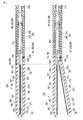
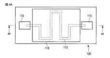
まず、この発熱の機構を構成する、発熱チップ100、中継チップ320、及び接続チップ330について説明する。発熱チップ100は、図4A及び図4Bに示すように、アルミナ製の基板111を用いて形成されている。基板111の主面の一方である表面には、発熱用のPt薄膜である抵抗パターン113が形成されている。また、基板111の表面の、長方形の2つの短辺近傍には、それぞれ矩形の電極115が形成されている。ここで、電極115は、抵抗パターン113のそれぞれの端部に接続している。  First, theheat generating chip 100, therelay chip 320, and theconnection chip 330 that constitute the heat generation mechanism will be described. As shown in FIGS. 4A and 4B, theheat generating chip 100 is formed using analumina substrate 111. Aresistance pattern 113 that is a Pt thin film for heat generation is formed on one surface of the main surface of thesubstrate 111. In addition,rectangular electrodes 115 are formed on the surface of thesubstrate 111 in the vicinity of the two short sides of the rectangle. Here, theelectrode 115 is connected to each end of theresistance pattern 113.

電極115が形成されている部分を除き、抵抗パターン113上を含む基板111の表面には、例えばポリイミドで形成された絶縁膜117が形成されている。さらに、絶縁膜117の上面には、基板111の抵抗パターン113及び絶縁膜117を含む側の熱的不均一さを小さくするために、熱伝導性のよい物質で形成された均熱部材118が設けられている。均熱部材118の材料は、金属、特に銅やアルミニウム等が好ましい。なお、抵抗パターン113と均熱部材118とは、絶縁膜117によって、電気的に絶縁されることになる。  An insulatingfilm 117 made of, for example, polyimide is formed on the surface of thesubstrate 111 including on theresistance pattern 113 except for a portion where theelectrode 115 is formed. Further, on the upper surface of the insulatingfilm 117, aheat equalizing member 118 made of a material having good thermal conductivity is provided in order to reduce thermal non-uniformity on the side of thesubstrate 111 including theresistance pattern 113 and the insulatingfilm 117. Is provided. The material of theheat equalizing member 118 is preferably a metal, particularly copper or aluminum. Theresistance pattern 113 and theheat equalizing member 118 are electrically insulated by the insulatingfilm 117.

基板111の裏面全面には、接合用金属層119が形成されている。電極115と接合用金属層119とは、例えばTiとCuとNiとAuとからなる多層の膜である。これら電極115と接合用金属層119とは、ワイヤーボンディングやハンダ付けに対して安定した強度を有している。接合用金属層119は、例えば第1の高周波電極266に発熱チップ100をハンダ付けする際に、接合が安定するように設けられている。  Abonding metal layer 119 is formed on the entire back surface of thesubstrate 111. Theelectrode 115 and thebonding metal layer 119 are multilayer films made of, for example, Ti, Cu, Ni, and Au. Theseelectrodes 115 andbonding metal layer 119 have a stable strength against wire bonding and soldering. Thebonding metal layer 119 is provided so that the bonding is stable when theheat generating chip 100 is soldered to the first high-frequency electrode 266, for example.

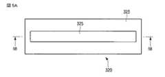
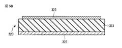
中継チップ320について、図5Aと図5Bとを参照して説明する。中継チップ320は、発熱チップ100と同様に、アルミナ製の基板323を用いて形成されている。基板323の表面には、電極325が形成されている。また、基板323の裏面全面には、接合用金属層327が形成されている。発熱チップ100の場合と同様に、電極325と接合用金属層327とは、例えばTiとCuとNiとAuとからなる多層の膜である。  Therelay chip 320 will be described with reference to FIGS. 5A and 5B. Similar to theheat generating chip 100, therelay chip 320 is formed using analumina substrate 323. Anelectrode 325 is formed on the surface of thesubstrate 323. Abonding metal layer 327 is formed on the entire back surface of thesubstrate 323. As in the case of theheat generating chip 100, theelectrode 325 and thebonding metal layer 327 are multilayer films made of, for example, Ti, Cu, Ni, and Au.

接続チップ330も、中継チップ320と同様の構成を有している。図6に示すように、接続チップ330は、アルミナ製の基板333と、基板333の表面に形成された電極339と、基板333の裏面全面に形成されている接合用金属層とを有している。  Theconnection chip 330 has the same configuration as therelay chip 320. As shown in FIG. 6, theconnection chip 330 includes analumina substrate 333, anelectrode 339 formed on the surface of thesubstrate 333, and a bonding metal layer formed on the entire back surface of thesubstrate 333. Yes.

発熱チップ100、中継チップ320、及び接続チップ330は、第1の高周波電極266及び第2の高周波電極276の、生体組織と接する面(第1の主面)とは反対側の面(第2の主面)に配設されている。ここで、発熱チップ100、中継チップ320、及び接続チップ330は、それぞれ、接合用金属層の表面と第1の高周波電極266又は第2の高周波電極276の第2の主面とをハンダ付けすることにより固定されている。  Theheat generating chip 100, therelay chip 320, and theconnection chip 330 are surfaces of the first high-frequency electrode 266 and the second high-frequency electrode 276 opposite to the surface (first main surface) in contact with the living tissue (second main surface). On the main surface). Here, each of theheat generating chip 100, therelay chip 320, and theconnection chip 330 solders the surface of the bonding metal layer and the second main surface of the first high-frequency electrode 266 or the second high-frequency electrode 276. It is fixed by.

第1の高周波電極266の場合を例に挙げて、図7を参照して説明する。第1の高周波電極266の基端部には、カッタ案内溝264を挟んで対称な位置に接続チップ330が配置されている。
第1の高周波電極266には、6個の発熱チップ100が、図7に示すように配置されている。すなわち、発熱チップ100は、基端側から先端側に向けてカッタ案内溝264を挟んで対称に2列に3個ずつ並べて配置されている。ここで、発熱チップ100は、それぞれ2つの電極115のうち一方を先端側に他方を基端側に向けて配置されている。第1の高周波電極266の先端部分には、中継チップ320が配置されている。
The case of the first high-frequency electrode 266 will be described as an example with reference to FIG. At the base end portion of the first high-frequency electrode 266, theconnection chip 330 is disposed at a symmetrical position with thecutter guide groove 264 interposed therebetween.
On the first high-frequency electrode 266, sixheat generating chips 100 are arranged as shown in FIG. That is, threeheat generating chips 100 are arranged in two rows symmetrically across thecutter guide groove 264 from the base end side to the tip end side. Here, each of theheat generating chips 100 is arranged with one of the twoelectrodes 115 facing the distal end and the other facing the proximal end. Arelay chip 320 is disposed at the tip of the first high-frequency electrode 266.

2つの接続チップ330には、それぞれ発熱チップ用通電ライン281,282がハンダ付けされている。発熱チップ用通電ライン281と発熱チップ用通電ライン282とは、対をなしており、ケーブル228を介してエネルギ源214に接続されている。  The twoconnection chips 330 are soldered with heatingchip energization lines 281 and 282, respectively. The heatingchip energization line 281 and the heatingchip energization line 282 make a pair and are connected to theenergy source 214 via thecable 228.

接続チップ330の電極339の先端側と、それらと隣接する発熱チップ100の電極115とは、ワイヤーボンディングによって形成されたワイヤー351により接続されている。同様に、各接続チップの隣接する電極115同士は、それぞれワイヤーボンディングによって形成されたワイヤー351により接続されている。また、最も先端側に配置された2つの発熱チップ100の先端側の電極115は、それぞれ中継チップ320の電極325に、ワイヤーボンディングによって形成されたワイヤー351により接続されている。中継チップ320を介して接続するのは、第1の高周波電極266の長手方向に並ぶ発熱チップ100の間隔よりも、第1の高周波電極266の先端部において第1の高周波電極266の長手方向と直交する方向に配置された2つの発熱チップ100の間隔が大きく、ワイヤーボンディングによる接続が困難であるからである。以上によって、発熱チップ用通電ライン281、6つの発熱チップ100の抵抗パターン113、及び発熱チップ用通電ライン282は、直列に接続される。  The tip side of theelectrode 339 of theconnection chip 330 and theelectrode 115 of theheat generating chip 100 adjacent thereto are connected by awire 351 formed by wire bonding. Similarly,adjacent electrodes 115 of each connection chip are connected bywires 351 formed by wire bonding. In addition, theelectrodes 115 on the tip side of the twoheat generating chips 100 arranged on the most tip side are respectively connected to theelectrodes 325 of therelay chip 320 bywires 351 formed by wire bonding. Therelay chip 320 is connected to the longitudinal direction of the first high-frequency electrode 266 at the tip of the first high-frequency electrode 266 rather than the interval between theheat generating chips 100 arranged in the longitudinal direction of the first high-frequency electrode 266. This is because the distance between the twoheat generating chips 100 arranged in the orthogonal direction is large and it is difficult to connect by wire bonding. As described above, the heatingchip energization line 281, theresistance pattern 113 of the sixheating chips 100, and the heatingchip energization line 282 are connected in series.

第1の高周波電極266上には、発熱チップ100、中継チップ320、並びに接続チップ330、及びそれらを接続するワイヤー351を覆うように、例えばシリコーンからなる封止剤が塗布されて、封止膜360が図3に示すように形成されている。ここで、封止膜360は、均熱部材118の熱伝導率(第1の熱伝導率)よりも低い熱伝導率(第2の熱伝導率)を有している。  On the first high-frequency electrode 266, a sealing agent made of, for example, silicone is applied so as to cover theheat generating chip 100, therelay chip 320, theconnection chip 330, and thewire 351 connecting them, and asealing film 360 is formed as shown in FIG. Here, the sealingfilm 360 has a thermal conductivity (second thermal conductivity) lower than the thermal conductivity (first thermal conductivity) of the soakingmember 118.

エネルギ源214から出力された電流は、6つの発熱チップ100のそれぞれの抵抗パターン113を流れる。その結果、各抵抗パターン113は発熱する。抵抗パターン113が発熱すると、第1の高周波電極266にその熱が伝達される。この熱により、第1の高周波電極266に接した生体組織が焼灼される。  The current output from theenergy source 214 flows through theresistance patterns 113 of the sixheat generating chips 100. As a result, eachresistance pattern 113 generates heat. When theresistance pattern 113 generates heat, the heat is transmitted to the first high-frequency electrode 266. The living tissue in contact with the first high-frequency electrode 266 is cauterized by this heat.

発熱チップ100で生じた熱を効率よく第1の高周波電極266へ伝えるために、封止膜360、及びその周囲の第1の保持部材本体262は、低い熱伝導率を有するように構成されることが好ましい。前述のとおり、封止膜360の熱伝導率は、均熱部材118の熱伝導率よりも低い。そして、封止膜360の熱伝導率は、第1の高周波電極266や基板111の熱伝導率よりも低いことが好ましい。封止膜360及び第1の保持部材本体262の熱伝導率が低いことで、損失の少ない熱伝導が実現される。  In order to efficiently transmit heat generated in theheat generating chip 100 to the first high-frequency electrode 266, the sealingfilm 360 and the first holdingmember body 262 around the sealingfilm 360 are configured to have low thermal conductivity. It is preferable. As described above, the thermal conductivity of the sealingfilm 360 is lower than the thermal conductivity of the soakingmember 118. The thermal conductivity of the sealingfilm 360 is preferably lower than the thermal conductivity of the first high-frequency electrode 266 and thesubstrate 111. Since the thermal conductivity of the sealingfilm 360 and the first holdingmember body 262 is low, thermal conduction with less loss is realized.

なお、上記説明では、製造工程を考慮して、均熱部材118は、発熱チップ100の一部として形成されているものとして説明したが、均熱部材118を有さない発熱チップの、第1の高周波電極266又は第2の高周波電極276の第2の主面と接合する第3の主面とは反対側の第4の主面(抵抗パターン113が形成されている側の面)に、均熱部材118として機能する例えば金属膜を、別体として貼り合わせるように構成しても、後述する機能及び効果と同様の機能及び効果が得られることはもちろんである。  In the above description, theheat equalizing member 118 is described as being formed as a part of theheat generating chip 100 in consideration of the manufacturing process, but the first heat generating chip that does not have theheat equalizing member 118 is described. On the fourth main surface opposite to the third main surface joined to the second main surface of the high-frequency electrode 266 or the second high-frequency electrode 276 (the surface on the side where theresistance pattern 113 is formed), Of course, even if a metal film that functions as theheat equalizing member 118 is bonded to a separate body, for example, functions and effects similar to those described below can be obtained.

このように、例えば第1の高周波電極266又は第2の高周波電極276は、生体組織に熱を伝える伝熱部として機能し、例えば抵抗パターン113は、電気抵抗パターンとして機能し、例えば発熱チップ100は、第3の主面側に電気抵抗パターンが形成され、第4の主面において前記伝熱部と接合し、当該電気抵抗パターンに電力を投入することで当該伝熱部を加熱する発熱チップとして機能し、例えば均熱部材118は、電気抵抗パターンを挟んで伝熱部と対峙するように発熱チップの第3の主面に配置された第1の熱伝導率を有する均熱部材として機能し、例えば封止膜360は、前記伝熱部の第2の主面、発熱チップ、及び均熱部材を覆い、第1の熱伝導率よりも低い第2の熱伝導率を有する封止部材として機能する。  Thus, for example, the first high-frequency electrode 266 or the second high-frequency electrode 276 functions as a heat transfer unit that transfers heat to the living tissue, for example, theresistance pattern 113 functions as an electrical resistance pattern, for example, theheating chip 100. Is a heat generating chip that has an electric resistance pattern formed on the third main surface side, is joined to the heat transfer portion on the fourth main surface, and heats the heat transfer portion by supplying electric power to the electric resistance pattern. For example, theheat equalizing member 118 functions as a heat equalizing member having a first thermal conductivity disposed on the third main surface of the heat generating chip so as to face the heat transfer portion across the electric resistance pattern. For example, the sealingfilm 360 covers the second main surface of the heat transfer section, the heat generating chip, and the heat equalizing member, and has a second thermal conductivity lower than the first thermal conductivity. Function as.

次に本実施形態に係る治療用処置装置210の動作を説明する。術者は、予めエネルギ源214の入力部を操作して、治療用処置装置210の出力条件、例えば、高周波エネルギ出力の設定電力、熱エネルギ出力の目標温度、加熱時間等を設定しておく。それぞれの値を個別に設定するように構成してもよいし、術式に応じた設定値のセットを選択するように構成してもよい。  Next, the operation of thetherapeutic treatment apparatus 210 according to this embodiment will be described. The surgeon operates the input unit of theenergy source 214 in advance to set the output conditions of thetherapeutic treatment device 210, for example, the set power of the high frequency energy output, the target temperature of the thermal energy output, the heating time, and the like. Each value may be set individually, or may be configured to select a set of setting values according to the technique.

エネルギ処置具212の保持部226及びシャフト224は、例えば、腹壁を通して腹腔内に挿入される。術者は、操作ノブ232を操作して、保持部226を開閉させ、第1の保持部材260と第2の保持部材270とによって、処置対象の生体組織を把持する。このとき、第1の保持部材260に設けられた第1の高周波電極266と第2の保持部材270に設けられた第2の高周波電極276との両方の第1の主面に、処置対象の生体組織が接触している。  The holdingpart 226 and theshaft 224 of the energy treatment tool 212 are inserted into the abdominal cavity through the abdominal wall, for example. The surgeon operates theoperation knob 232 to open and close the holdingportion 226, and grips the living tissue to be treated by the first holdingmember 260 and the second holdingmember 270. At this time, the first main surface of both the first high-frequency electrode 266 provided on the first holdingmember 260 and the second high-frequency electrode 276 provided on the second holdingmember 270 is to be treated. Living tissue is in contact.

術者は、保持部226によって処置対象の生体組織を把持したら、フットスイッチ216を操作する。フットスイッチ216がONに切り換えられると、エネルギ源214から、ケーブル228を介して第1の高周波電極266及び第2の高周波電極276に、予め設定した設定電力の高周波電力が供給される。供給される電力は、例えば、20W〜80W程度である。その結果、生体組織は発熱し、組織が焼灼される。この焼灼により、当該組織は変性し、凝固する。  When the operator grasps the biological tissue to be treated by the holdingunit 226, the operator operates the foot switch 216. When the foot switch 216 is switched ON, high-frequency power having a preset set power is supplied from theenergy source 214 to the first high-frequency electrode 266 and the second high-frequency electrode 276 via thecable 228. The supplied power is, for example, about 20W to 80W. As a result, the living tissue generates heat and the tissue is cauterized. By this cauterization, the tissue is denatured and solidified.

次にエネルギ源214は、高周波エネルギの出力を停止した後、第1の高周波電極266の温度が目標温度になるように発熱チップ100に電力を供給する。ここで、目標温度は、例えば100℃〜300℃である。このとき電流は、エネルギ源214から、ケーブル228、発熱チップ用通電ライン281,282、接続チップ330、及びワイヤー351を介して、各発熱チップ100の抵抗パターン113を流れる。各発熱チップ100の抵抗パターン113は、電流によって発熱する。抵抗パターン113で発生した熱は、基板111及び接合用金属層119を介して、当該発熱チップ100の第4の主面とその第2の主面とが接合している第1の高周波電極266に伝わる。その結果、第1の高周波電極266の温度は上昇する。同様に、第2の高周波電極276の温度も、第2の高周波電極276に配置された各発熱チップ100を流れる電流による発熱で上昇する。その結果、第1の高周波電極266又は第2の高周波電極276の第1の主面と接触している生体組織は更に焼灼され、更に凝固する。
加熱によって生体組織が凝固したら、熱エネルギの出力を停止する。最後に術者は、操作ノブ232を操作してカッタ254を移動させ、生体組織を切断する。以上によって生体組織の処置が完了する。
Next, after stopping the output of the high frequency energy, theenergy source 214 supplies power to theheat generating chip 100 so that the temperature of the firsthigh frequency electrode 266 becomes the target temperature. Here, target temperature is 100 to 300 degreeC, for example. At this time, the current flows from theenergy source 214 through theresistance pattern 113 of eachheat generating chip 100 through thecable 228, the heat generatingchip conducting lines 281 and 282, theconnection chip 330, and thewire 351. Theresistance pattern 113 of eachheat generating chip 100 generates heat by current. The heat generated in theresistance pattern 113 is a first high-frequency electrode 266 in which the fourth main surface of theheat generating chip 100 and the second main surface are bonded via thesubstrate 111 and thebonding metal layer 119. It is transmitted to. As a result, the temperature of the first high-frequency electrode 266 increases. Similarly, the temperature of the second high-frequency electrode 276 also rises due to heat generated by the current flowing through each heat-generating chip 100 disposed on the second high-frequency electrode 276. As a result, the living tissue in contact with the first main surface of the first high-frequency electrode 266 or the second high-frequency electrode 276 is further cauterized and further solidified.
When the living tissue is solidified by heating, the output of thermal energy is stopped. Finally, the operator operates theoperation knob 232 to move thecutter 254 and cut the living tissue. The treatment of the living tissue is thus completed.

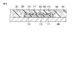
ここで、均熱部材118が配置されている効果について説明する。仮に均熱部材118が存在しなかった場合の、第1の高周波電極266、発熱チップ100、及び封止膜360部分の拡大断面図を図8に示す。第1の高周波電極266及び発熱チップ100等を覆う封止膜360には、製造過程で生じざるを得ないボイドなどに起因した局部的な空気層362が混入することがある。この空気層362の熱伝導率は、封止膜360のその他の部分の熱伝導率よりも非常に低い。このため、空気層362が、発熱チップ100の絶縁膜117に接して存在する場合、熱流を模式的に表すと図9に示すようになる。図9において矢印は、熱流を模式的に示している。図9において左に示したように、発熱チップ100の第3の主面側に形成された抵抗パターン113−1で発生した熱は、絶縁膜117を介して、封止膜360へと流れる。これに対して、図9において右に示したように、同じく第3の主面に形成された抵抗パターン113−2で発生した熱は、空気層362に遮られて、絶縁膜117から封止膜360へ流れにくくなっている。そのため、空気層362がある抵抗パターン113の近傍(例えば図9において斜線を付した部分)は、他の場所に比べて局所的に高温となる。その結果、高温となる部分で、抵抗パターン113が焼切れる可能性がある。  Here, the effect that the soaking | uniform-heating member 118 is arrange | positioned is demonstrated. FIG. 8 shows an enlarged cross-sectional view of the first high-frequency electrode 266, theheating chip 100, and thesealing film 360 when the soakingmember 118 is not present. The sealingfilm 360 covering the first high-frequency electrode 266, theheat generating chip 100, and the like may contain alocal air layer 362 due to a void or the like that must be generated in the manufacturing process. The thermal conductivity of theair layer 362 is much lower than the thermal conductivity of other portions of the sealingfilm 360. Therefore, when theair layer 362 exists in contact with the insulatingfilm 117 of theheat generating chip 100, the heat flow is schematically shown in FIG. In FIG. 9, the arrows schematically show the heat flow. As shown on the left in FIG. 9, the heat generated in the resistance pattern 113-1 formed on the third main surface side of theheat generating chip 100 flows to thesealing film 360 through the insulatingfilm 117. On the other hand, as shown on the right in FIG. 9, the heat generated in the resistance pattern 113-2 formed on the third main surface is blocked by theair layer 362 and sealed from the insulatingfilm 117. It is difficult to flow to thefilm 360. Therefore, the vicinity of theresistance pattern 113 with the air layer 362 (for example, the hatched portion in FIG. 9) is locally hotter than other places. As a result, there is a possibility that theresistance pattern 113 is burned out at a portion where the temperature becomes high.

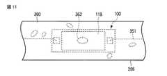
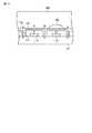
上記に対して、本実施形態では、発熱チップ100の絶縁膜117と封止膜360との間に、均熱部材118が配置されている。本実施形態に係る第1の高周波電極266、発熱チップ100、及び封止膜360部分の拡大断面図を図10に、上面図を図11にそれぞれ示す。また、抵抗パターン113の周辺の熱流を図12に模式的に示す。図12において矢印は、熱流を模式的に示している。本実施形態の場合、発熱チップ100に接触して空気層362が形成されたとしても、図12に示すように、空気層362がある部分において、熱は、均熱部材118で拡散され、均熱部材118と封止膜360とが直接接している部分から、封止膜360へと流れる。その結果、図9を参照して説明したような、局所的に高温となる部分が生じない。  In contrast, in the present embodiment, the soakingmember 118 is disposed between the insulatingfilm 117 and thesealing film 360 of theheat generating chip 100. FIG. 10 is an enlarged cross-sectional view of the first high-frequency electrode 266, theheat generating chip 100, and thesealing film 360 according to this embodiment, and FIG. Further, the heat flow around theresistance pattern 113 is schematically shown in FIG. In FIG. 12, the arrows schematically show the heat flow. In the case of this embodiment, even if theair layer 362 is formed in contact with theheat generating chip 100, as shown in FIG. It flows from the portion where thethermal member 118 and thesealing film 360 are in direct contact to thesealing film 360. As a result, there is no locally high temperature portion as described with reference to FIG.

なお、均熱部材118の形状や大きさ等は、図4Aに示すようなものには限定されない。しかしながら、前記のような熱を拡散させる効果を得るために、均熱部材118は、少なくとも抵抗パターン113が形成されている位置の直上にあたる、抵抗パターン113に対応する位置には設けられていることが好ましい。  Note that the shape, size, and the like of the soakingmember 118 are not limited to those shown in FIG. 4A. However, in order to obtain the effect of diffusing heat as described above, theheat equalizing member 118 is provided at a position corresponding to theresistance pattern 113 at least immediately above the position where theresistance pattern 113 is formed. Is preferred.

以上のように本実施形態によれば、均熱部材118の配置に基づく温度を均一化する効果により、発熱チップ100の温度が局部的に上昇することを防止できる。その結果、例えば抵抗パターン113の焼切れを含む発熱チップ100の損傷、すなわち、エネルギ処置具212の故障を防止することができる。以上のように、本実施形態によれば、耐久性の高い治療用処置装置を提供することができる。  As described above, according to the present embodiment, the temperature of theheat generating chip 100 can be prevented from rising locally due to the effect of equalizing the temperature based on the arrangement of the soakingmembers 118. As a result, for example, damage to theheat generating chip 100 including burnout of theresistance pattern 113, that is, failure of the energy treatment tool 212 can be prevented. As described above, according to this embodiment, it is possible to provide a highly durable treatment apparatus.

[第2の実施形態]
次に、本発明の第2の実施形態について説明する。ここでは、第1の実施形態との相違点について説明し、同一の部分については同一の符号を付して、その説明は省略する。本実施形態に係る発熱チップ120の上面図を図13Aに、断面図を13Bにそれぞれ示す。これら図に示すように、本実施形態に係る発熱チップ120では、絶縁膜117には、貫通穴117aが設けられており、この貫通穴117aに形成された伝熱柱118aが、均熱部材118と基板111と接触している。この伝熱柱118aは、均熱部材118と同様に伝熱性のよい材料からなる。伝熱柱118aは、均熱部材118と一体として形成されてもよい。伝熱柱118aによって、金属層である均熱部材118とチップ基板である基板111とは、熱的に結合されている。なお、伝熱柱118aは、抵抗パターン113には接触しないように形成されている。このように、例えば伝熱柱118aは、熱結合部材として機能する。
[Second Embodiment]
Next, a second embodiment of the present invention will be described. Here, differences from the first embodiment will be described, and the same portions will be denoted by the same reference numerals and description thereof will be omitted. A top view of theheat generating chip 120 according to the present embodiment is shown in FIG. 13A, and a cross-sectional view is shown in 13B. As shown in these drawings, in theheat generating chip 120 according to the present embodiment, the insulatingfilm 117 is provided with a throughhole 117a. And thesubstrate 111 are in contact with each other. Theheat transfer column 118a is made of a material having good heat transfer properties, like theheat equalizing member 118. Theheat transfer column 118 a may be formed integrally with theheat equalizing member 118. Theheat equalizing member 118 that is a metal layer and thesubstrate 111 that is a chip substrate are thermally coupled by theheat transfer column 118a. Note that theheat transfer column 118 a is formed so as not to contact theresistance pattern 113. Thus, for example, theheat transfer column 118a functions as a heat coupling member.

本実施形態に係る発熱チップ120によれば、発熱チップ120の第3の主面側に形成された抵抗パターン113で発生した熱の流れは次のようになる。図14に、発熱チップ120における熱流を模式的に示す。ここで図14において矢印は、熱流を模式的に示している。この図に示すように、第1の実施形態と同様に、封止膜360に生じた空気層362が発熱チップ100と接しても、熱は、均熱部材118により拡散して、局所的に高温となることを防止することができる。さらに、均熱部材118内を拡散した熱は、伝熱柱118aを介して、基板111に流れる。  According to theheat generating chip 120 according to the present embodiment, the flow of heat generated in theresistance pattern 113 formed on the third main surface side of theheat generating chip 120 is as follows. FIG. 14 schematically shows the heat flow in theheat generating chip 120. Here, the arrows in FIG. 14 schematically show the heat flow. As shown in this figure, as in the first embodiment, even if theair layer 362 generated in thesealing film 360 is in contact with theheat generating chip 100, the heat is diffused by theheat equalizing member 118 and locally. High temperature can be prevented. Further, the heat diffused in the soakingmember 118 flows to thesubstrate 111 through theheat transfer column 118a.

ここで、封止膜360には、前記のとおり熱伝導率が低い物質を用いており、封止膜360の熱伝導率は、基板111の熱伝導率よりも低い。したがって、均熱部材118で拡散した熱は、封止膜360よりも基板111へより多く流れる。その結果、発熱チップ120の第4の主面とその第2の主面が接合している第1の高周波電極266への熱伝導の効率が上昇する。すなわち、抵抗パターン113で発生した熱を、より効率的に用いることができる。  Here, the sealingfilm 360 is made of a material having low thermal conductivity as described above, and the thermal conductivity of the sealingfilm 360 is lower than the thermal conductivity of thesubstrate 111. Therefore, more heat diffused by the soakingmember 118 flows to thesubstrate 111 than the sealingfilm 360. As a result, the efficiency of heat conduction to the first high-frequency electrode 266 where the fourth main surface of theheat generating chip 120 and the second main surface are joined increases. That is, the heat generated in theresistance pattern 113 can be used more efficiently.

以上のように本実施形態によれば、第1の実施形態の場合と同様に、均熱部材118の配置に基づく温度を均一化する効果により、発熱チップ100の温度が局部的に上昇することを防止することができる。その結果、例えば抵抗パターン113の焼切れを含む発熱チップ100の損傷、すなわち、エネルギ処置具212の故障を防止することができ、耐久性の高い治療用処置装置を提供することができる。さらに、伝熱柱118aにより、熱を基板111に流し、第1の高周波電極266を加熱するための熱の割合を増加させることができる。その結果、エネルギ効率の高い治療用処置装置を提供することができる。  As described above, according to the present embodiment, similarly to the first embodiment, the temperature of theheat generating chip 100 increases locally due to the effect of equalizing the temperature based on the arrangement of theheat equalizing members 118. Can be prevented. As a result, for example, damage to theheat generating chip 100 including burnout of theresistance pattern 113, that is, failure of the energy treatment tool 212 can be prevented, and a highly durable treatment apparatus can be provided. Furthermore, theheat transfer column 118a allows heat to flow to thesubstrate 111, and the rate of heat for heating the first high-frequency electrode 266 can be increased. As a result, a treatment apparatus with high energy efficiency can be provided.

なお、本発明は上記実施形態そのままに限定されるものではなく、実施段階ではその要旨を逸脱しない範囲で構成要素を変形して具体化できる。また、上記実施形態に開示されている複数の構成要素の適宜な組み合わせにより、種々の発明を形成できる。例えば、実施形態に示される全構成要素から幾つかの構成要素を削除しても、発明が解決しようとする課題の欄で述べられた課題が解決でき、かつ、発明の効果が得られる場合には、この構成要素が削除された構成も発明として抽出され得る。  Note that the present invention is not limited to the above-described embodiment as it is, and can be embodied by modifying the constituent elements without departing from the scope of the invention in the implementation stage. In addition, various inventions can be formed by appropriately combining a plurality of components disclosed in the embodiment. For example, even if some constituent elements are deleted from all the constituent elements shown in the embodiment, the problem described in the column of problems to be solved by the invention can be solved and the effect of the invention can be obtained. The configuration in which this component is deleted can also be extracted as an invention.

100…発熱チップ、111…基板、113…抵抗パターン、115…電極、117…ポリイミド膜、117a…貫通穴、118…均熱部材、118a…伝熱柱、119…接合用金属層、120…発熱チップ、210…治療用処置装置、212…エネルギ処置具、214…エネルギ源、216…フットスイッチ、222…ハンドル、224…シャフト、226…保持部、228…ケーブル、232…操作ノブ、242…筒体、244…シース、252…駆動ロッド、254…カッタ、256…支持ピン、258…弾性部材、260…第1の保持部材、262…第1の保持部材本体、264,274…カッタ案内溝、266…第1の高周波電極、268…高周波電極用通電ライン、270…第2の保持部材、272…第2の保持部材本体、276…第2の高周波電極、281,282…発熱チップ用通電ライン、320…中継チップ、323…基板、325…電極、327…接合用金属層、330…接続チップ、333…基板、339…電極、351…ワイヤー、360…封止膜、362…空気層。  DESCRIPTION OFSYMBOLS 100 ... Exothermic chip | tip, 111 ... Board | substrate, 113 ... Resistance pattern, 115 ... Electrode, 117 ... Polyimide film, 117a ... Through-hole, 118 ... Soaking member, 118a ... Heat-transfer pillar, 119 ... Metal layer for joining, 120 ... Heat generation Chip, 210 ... treatment device, 212 ... energy treatment tool, 214 ... energy source, 216 ... foot switch, 222 ... handle, 224 ... shaft, 226 ... holding part, 228 ... cable, 232 ... operation knob, 242 ... cylinder Body, 244 ... sheath, 252 ... drive rod, 254 ... cutter, 256 ... support pin, 258 ... elastic member, 260 ... first holding member, 262 ... first holding member body, 264, 274 ... cutter guide groove, 266 ... first high-frequency electrode, 268 ... high-frequency electrode energization line, 270 ... second holding member, 272 ... second holding member body, 27 2nd high frequency electrode, 281, 282 ... Heating chip energization line, 320 ... Relay chip, 323 ... Substrate, 325 ... Electrode, 327 ... Joining metal layer, 330 ... Connection chip, 333 ... Substrate, 339 ... Electrode, 351 ... wire, 360 ... sealing film, 362 ... air layer.

Claims (5)

Translated fromJapanese
生体組織を目標温度で加熱して治療するための治療用処置装置であって、
表裏をなす第1の主面と第2の主面のうち該第1の主面において前記生体組織に接触して該生体組織に熱を伝える伝熱部と、
表裏をなす第3の主面と第4の主面のうち、該第3の主面側に電気抵抗パターンが形成され、該第4の主面において前記伝熱部の前記第2の主面と接合し、該電気抵抗パターンに電力を投入することで前記伝熱部を加熱する発熱チップと、
前記電気抵抗パターンを挟んで前記伝熱部と対峙するように前記発熱チップの前記第3の主面に配置された第1の熱伝導率を有する均熱部材と、
前記伝熱部の前記第2の主面、前記発熱チップ、及び前記均熱部材を覆い、前記第1の熱伝導率よりも低い第2の熱伝導率を有する封止部材と、
を具備することを特徴とする治療用処置装置。
A therapeutic treatment device for heating and treating a living tissue at a target temperature,
Of the first main surface and the second main surface forming the front and back, a heat transfer section that contacts the living tissue on the first main surface and transfers heat to the living tissue;
Of the third main surface and the fourth main surface forming the front and back, an electric resistance pattern is formed on the third main surface side, and the second main surface of the heat transfer section is formed on the fourth main surface. And a heating chip that heats the heat transfer part by applying power to the electrical resistance pattern,
A soaking member having a first thermal conductivity disposed on the third main surface of the heat generating chip so as to face the heat transfer portion across the electrical resistance pattern;
A sealing member that covers the second main surface of the heat transfer section, the heat generating chip, and the heat equalizing member, and has a second thermal conductivity lower than the first thermal conductivity;
A therapeutic treatment apparatus comprising:
前記均熱部材は、前記発熱チップの前記第3の主面のうち、少なくとも前記電気抵抗パターンに対応する位置には設けられていることを特徴とする請求項1に記載の治療用処置装置。  The treatment apparatus according to claim 1, wherein the heat equalizing member is provided at a position corresponding to at least the electric resistance pattern in the third main surface of the heat generating chip. 前記均熱部材は金属層であることを特徴とする請求項1又は2に記載の治療用処置装置。  The therapeutic treatment apparatus according to claim 1, wherein the heat equalizing member is a metal layer. 前記電気抵抗パターンと前記金属層との間には、電気絶縁薄膜が介在していることを特徴とする請求項3に記載の治療用処置装置。  The treatment apparatus according to claim 3, wherein an electrically insulating thin film is interposed between the electrical resistance pattern and the metal layer. 前記電気抵抗パターンは、前記発熱チップのチップ基板の上に形成されており、
前記金属層と前記チップ基板とは、前記電気抵抗パターンと接しない前記第2の熱伝導率よりも高い熱伝導率を有する熱結合部材によって、熱的に結合されている、
ことを特徴とする請求項3に記載の治療用処置装置。
The electrical resistance pattern is formed on a chip substrate of the heat generating chip,
The metal layer and the chip substrate are thermally coupled by a thermal coupling member having a thermal conductivity higher than the second thermal conductivity that is not in contact with the electrical resistance pattern.
The therapeutic treatment device according to claim 3.
JP2011063141A2011-03-222011-03-22 Therapeutic treatment deviceExpired - Fee RelatedJP5704985B2 (en)

Priority Applications (1)

Application NumberPriority DateFiling DateTitle
JP2011063141AJP5704985B2 (en)2011-03-222011-03-22 Therapeutic treatment device

Applications Claiming Priority (1)

Application NumberPriority DateFiling DateTitle
JP2011063141AJP5704985B2 (en)2011-03-222011-03-22 Therapeutic treatment device

Publications (3)

Publication NumberPublication Date
JP2012196340Atrue JP2012196340A (en)2012-10-18
JP2012196340A5 JP2012196340A5 (en)2014-03-13
JP5704985B2 JP5704985B2 (en)2015-04-22

Family

ID=47179207

Family Applications (1)

Application NumberTitlePriority DateFiling Date
JP2011063141AExpired - Fee RelatedJP5704985B2 (en)2011-03-222011-03-22 Therapeutic treatment device

Country Status (1)

CountryLink
JP (1)JP5704985B2 (en)

Cited By (3)

* Cited by examiner, † Cited by third party
Publication numberPriority datePublication dateAssigneeTitle
WO2016166817A1 (en)*2015-04-142016-10-20オリンパス株式会社Therapeutic energy-imparting structure, and medical treatment device
WO2018198339A1 (en)*2017-04-282018-11-01オリンパス株式会社Energy treatment tool and treatment system
CN113543738A (en)*2018-12-102021-10-22博世健康爱尔兰有限公司Ceramic applicator for transcutaneous energy delivery

Citations (4)

* Cited by examiner, † Cited by third party
Publication numberPriority datePublication dateAssigneeTitle
JPH0682051A (en)*1992-09-071994-03-22Matsushita Electric Ind Co LtdElectric floor heating device
JPH08305197A (en)*1995-05-101996-11-22Brother Ind Ltd Heating roller for fixing
JP2005348820A (en)*2004-06-082005-12-22Olympus CorpHeating element, medical treatment tool and apparatus using thereof
US20090248002A1 (en)*2008-04-012009-10-01Tomoyuki TakashinoTreatment system, and treatment method for living tissue using energy

Patent Citations (6)

* Cited by examiner, † Cited by third party
Publication numberPriority datePublication dateAssigneeTitle
JPH0682051A (en)*1992-09-071994-03-22Matsushita Electric Ind Co LtdElectric floor heating device
JPH08305197A (en)*1995-05-101996-11-22Brother Ind Ltd Heating roller for fixing
JP2005348820A (en)*2004-06-082005-12-22Olympus CorpHeating element, medical treatment tool and apparatus using thereof
US20050288747A1 (en)*2004-06-082005-12-29Olympus CorporationHeat generating element, medical therapeutic instrument implementing the same, and treatment apparatus
US20090248002A1 (en)*2008-04-012009-10-01Tomoyuki TakashinoTreatment system, and treatment method for living tissue using energy
JP2009247893A (en)*2008-04-012009-10-29Olympus Medical Systems CorpTreatment system for therapy

Cited By (8)

* Cited by examiner, † Cited by third party
Publication numberPriority datePublication dateAssigneeTitle
WO2016166817A1 (en)*2015-04-142016-10-20オリンパス株式会社Therapeutic energy-imparting structure, and medical treatment device
CN107427319A (en)*2015-04-142017-12-01奥林巴斯株式会社Treatment assigns construction and medical intervention device with energy
US20180021079A1 (en)*2015-04-142018-01-25Olympus CorporationTherapeutic energy applying structure and medical treatment device
JPWO2016166817A1 (en)*2015-04-142018-02-08オリンパス株式会社 Therapeutic energy application structure and medical treatment apparatus
WO2018198339A1 (en)*2017-04-282018-11-01オリンパス株式会社Energy treatment tool and treatment system
US11666373B2 (en)2017-04-282023-06-06Olympus CorporationTreatment system and energy treatment tool
CN113543738A (en)*2018-12-102021-10-22博世健康爱尔兰有限公司Ceramic applicator for transcutaneous energy delivery
US12251152B2 (en)2018-12-102025-03-18Solta Medical Ireland LimitedCeramic applicator for transcutaneous delivery of energy

Also Published As

Publication numberPublication date
JP5704985B2 (en)2015-04-22

Similar Documents

PublicationPublication DateTitle
JP5631716B2 (en) Therapeutic treatment device
JP5988868B2 (en) Therapeutic treatment device
JP5931604B2 (en) Therapeutic treatment device
JP5988885B2 (en) Therapeutic treatment device
JP5622551B2 (en) THERAPEUTIC TREATMENT DEVICE AND ITS CONTROL METHOD
JP5687462B2 (en) Therapeutic treatment device
JP6274881B2 (en) Therapeutic treatment device
JP5797348B2 (en) THERAPEUTIC TREATMENT DEVICE AND MANUFACTURING METHOD THEREOF
JPWO2015022919A1 (en) Treatment tool and treatment system
JP2012239831A (en)Therapeutic treatment apparatus
JP2013106909A (en)Therapeutic treatment apparatus
JP5704985B2 (en) Therapeutic treatment device
JP6062130B1 (en) Treatment tool
JP2012165948A (en)Treatment device for therapy and method for producing the same
JP6458127B2 (en) Therapeutic energy application structure and medical treatment apparatus
JP2012249807A (en)Treatment apparatus for therapy, and control method for the same
JP2012249806A (en)Treatment apparatus for therapy
JP6000717B2 (en) THERAPEUTIC TREATMENT DEVICE AND ITS CONTROL METHOD
WO2018193493A1 (en)Surgical tool
WO2014148199A1 (en)Therapeutic treatment device
WO2018193492A1 (en)Surgical tool
JPWO2017163410A1 (en) Energy treatment tool

Legal Events

DateCodeTitleDescription
A711Notification of change in applicant

Free format text:JAPANESE INTERMEDIATE CODE: A711

Effective date:20121101

A521Written amendment

Free format text:JAPANESE INTERMEDIATE CODE: A821

Effective date:20121102

A521Written amendment

Free format text:JAPANESE INTERMEDIATE CODE: A523

Effective date:20140124

A621Written request for application examination

Free format text:JAPANESE INTERMEDIATE CODE: A621

Effective date:20140124

A131Notification of reasons for refusal

Free format text:JAPANESE INTERMEDIATE CODE: A131

Effective date:20140909

A977Report on retrieval

Free format text:JAPANESE INTERMEDIATE CODE: A971007

Effective date:20140912

A521Written amendment

Free format text:JAPANESE INTERMEDIATE CODE: A523

Effective date:20141001

TRDDDecision of grant or rejection written
A01Written decision to grant a patent or to grant a registration (utility model)

Free format text:JAPANESE INTERMEDIATE CODE: A01

Effective date:20150217

A61First payment of annual fees (during grant procedure)

Free format text:JAPANESE INTERMEDIATE CODE: A61

Effective date:20150224

R151Written notification of patent or utility model registration

Ref document number:5704985

Country of ref document:JP

Free format text:JAPANESE INTERMEDIATE CODE: R151

S531Written request for registration of change of domicile

Free format text:JAPANESE INTERMEDIATE CODE: R313531

R350Written notification of registration of transfer

Free format text:JAPANESE INTERMEDIATE CODE: R350

R250Receipt of annual fees

Free format text:JAPANESE INTERMEDIATE CODE: R250

LAPSCancellation because of no payment of annual fees

[8]ページ先頭

©2009-2025 Movatter.jp