JP2012193092A - Glass plate and method for producing the same - Google Patents
Glass plate and method for producing the sameDownload PDFInfo
- Publication number
- JP2012193092A JP2012193092AJP2011059847AJP2011059847AJP2012193092AJP 2012193092 AJP2012193092 AJP 2012193092AJP 2011059847 AJP2011059847 AJP 2011059847AJP 2011059847 AJP2011059847 AJP 2011059847AJP 2012193092 AJP2012193092 AJP 2012193092A
- Authority
- JP
- Japan
- Prior art keywords
- glass plate
- chemically strengthened
- surface layer
- tensile stress
- predetermined region
- Prior art date
- Legal status (The legal status is an assumption and is not a legal conclusion. Google has not performed a legal analysis and makes no representation as to the accuracy of the status listed.)
- Withdrawn
Links
Images


Landscapes
- Re-Forming, After-Treatment, Cutting And Transporting Of Glass Products (AREA)
- Surface Treatment Of Glass (AREA)
Abstract
Translated fromJapaneseDescription
Translated fromJapanese本発明は、化学強化後に切断してなるガラス板、およびその製造方法に関する。 The present invention relates to a glass plate cut after chemical strengthening and a method for producing the same.
近年、携帯電話やPDAなどの携帯機器において、ディスプレイ(タッチパネルを含む)の保護や美観などを高めるため、カバーガラス(保護ガラス)を用いることが多くなっている。また、ディスプレイの基板として、ガラス基板が広く用いられている。 In recent years, in a portable device such as a mobile phone or a PDA, a cover glass (protective glass) is often used in order to enhance the protection and aesthetics of a display (including a touch panel). A glass substrate is widely used as a display substrate.
一方、携帯機器の薄型化・軽量化が進行しており、携帯機器に用いられるガラス板の薄板化が進行している。ガラス板が薄くなると強度が低くなるので、ガラス板の強度不足を補うため、ガラス板を化学強化する技術が開発されている。 On the other hand, thinning and lightening of portable devices are progressing, and thinning of glass plates used for portable devices is progressing. Since the strength of the glass plate decreases as the glass plate becomes thinner, techniques for chemically strengthening the glass plate have been developed to compensate for the lack of strength of the glass plate.
化学強化は、ガラスの表面および裏面などをイオン交換して、圧縮応力が残留する表面層および裏面層などを形成する方法である。その反作用として、表面層と裏面層との間には、引張応力が残留する中間層が形成される。 Chemical strengthening is a method of forming a surface layer and a back surface layer in which compressive stress remains by ion exchange of the surface and the back surface of glass. As a reaction, an intermediate layer in which a tensile stress remains is formed between the front surface layer and the back surface layer.
化学強化ガラス板を大量生産する場合、製品サイズのガラス板を1枚ずつ化学強化するよりも、製品サイズよりも大型のガラス板を化学強化した後、切断して多面取りすることが効率的である。 When mass-producing chemically strengthened glass plates, it is more efficient to chemically temper glass plates that are larger than the product size and then cut and take multiple faces rather than chemically strengthening each product size glass plate one by one. is there.
そこで、化学強化ガラス板を切断する方法として、化学強化ガラス板の表面上の所定領域にレーザ光を照射し、表面上の切断予定線に沿って所定領域を移動させることで、熱応力でクラックを形成して切断を行う方法が提案されている(例えば、特許文献1参照)。 Therefore, as a method of cutting the chemically strengthened glass plate, a laser beam is irradiated to a predetermined region on the surface of the chemically strengthened glass plate, and the predetermined region on the surface is moved along the planned cutting line, thereby cracking due to thermal stress. There has been proposed a method of cutting by forming (see, for example, Patent Document 1).
ところで、上記の特許文献1では、レーザ光の光源として、炭酸ガスレーザが用いられるので、レーザ光の大部分が化学強化ガラス板の表面近傍で熱として吸収され、表面上の所定領域(レーザ照射領域)の直下に、残留引張応力よりも大きい引張応力が生じる。そのため、切断時に形成されるクラックが、所定領域を越えて、意図しない方向に急激に伸展しやすく、ガラスが粉砕されることもあった。 By the way, in the above-mentioned
この傾向は、中間層の残留引張応力が大きくなるほど顕著であり、従来、中間層の平均残留引張応力が40MPaを超えるガラス板は、切断後に化学強化して製造する必要があり、製造コストが高かった。 This tendency becomes more conspicuous as the residual tensile stress of the intermediate layer becomes larger. Conventionally, a glass plate having an average residual tensile stress of 40 MPa or higher needs to be chemically strengthened after cutting, and the manufacturing cost is high. It was.
一方で、中間層の平均残留引張応力が低いと、表面層や裏面層の最大残留圧縮応力なども低く、耐傷性が不足するという問題があった。 On the other hand, when the average residual tensile stress of the intermediate layer is low, the maximum residual compressive stress of the front surface layer and the back surface layer is also low, and there is a problem that the scratch resistance is insufficient.
本発明は、上記課題に鑑みてなされたものであって、化学強化されたものであって、耐傷性に優れた、安価なガラス板を提供することを目的とする。 The present invention has been made in view of the above problems, and has an object of providing an inexpensive glass plate that is chemically strengthened and excellent in scratch resistance.
上記目的を解決するため、本発明は、
化学強化後に切断してなり、圧縮応力が残留する表面層および裏面層と、該表面層と該裏面層との間に形成され、引張応力が残留する中間層とを有し、切断面である側端面に、圧縮応力が残留する領域と、引張応力が残留する領域とを有するガラス板において、
前記中間層の平均残留引張応力が40MPaを超えることを特徴とするガラス板を提供する。In order to solve the above object, the present invention provides:
It is a cut surface having a surface layer and a back surface layer that are cut after chemical strengthening and in which compressive stress remains, and an intermediate layer that is formed between the surface layer and the back surface layer and in which tensile stress remains. In the glass plate having a region where compressive stress remains and a region where tensile stress remains on the side end face,
An average residual tensile stress of the intermediate layer is more than 40 MPa.
本発明によれば、化学強化されたものであって、耐傷性に優れた、安価なガラス板を提供することができる。 According to the present invention, an inexpensive glass plate that is chemically strengthened and excellent in scratch resistance can be provided.
以下、本発明を実施するための形態について図面を参照して説明するが、本発明は、後述の実施形態に制限されない。本発明は、本発明の範囲を逸脱することなく、後述の実施形態に種々の変形および置換を加えることができる。 Hereinafter, modes for carrying out the present invention will be described with reference to the drawings. However, the present invention is not limited to the embodiments described below. The present invention can add various modifications and replacements to the embodiments described below without departing from the scope of the present invention.
[第1の実施形態]
第1の実施形態は、化学強化後に切断してなるガラス板に関する。[First Embodiment]
1st Embodiment is related with the glass plate formed by cut | disconnecting after chemical strengthening.
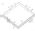
図1は、本発明の第1の実施形態に係るガラス板の斜視図である。 FIG. 1 is a perspective view of a glass plate according to the first embodiment of the present invention.
ガラス板10は、化学強化後に切断してなる。このガラス板10は、切断後に化学強化してなるものに比べて、生産効率が高いので、製造コストが低い。なお、切断方法は、第2および第3の実施形態で説明する。 The
化学強化は、ガラスの表面および裏面などをイオン交換し、圧縮応力が残留する表面層および裏面層などを形成する方法である。化学強化では、ガラスに含まれる小さなイオン半径のイオン(例えば、Liイオン、Naイオン)が、大きなイオン半径のイオン(例えば、Kイオン)に置換される。イオン交換用の処理液としては、特に限定されないが、例えばKNO3溶融塩などが用いられる。Chemical strengthening is a method of ion-exchanging the front surface and back surface of glass to form a front surface layer and a back surface layer in which compressive stress remains. In chemical strengthening, ions having a small ionic radius (for example, Li ions and Na ions) contained in glass are replaced with ions having a large ionic radius (for example, K ions). The treatment liquid for ion exchange is not particularly limited, and for example, KNO3 molten salt is used.
化学強化では、圧縮応力が残留する表面層および裏面層などを形成する反作用として、表面層と裏面層との間には、引張応力が残留する中間層が形成される。 In chemical strengthening, an intermediate layer in which a tensile stress remains is formed between the surface layer and the back surface layer as a reaction for forming a surface layer and a back surface layer in which a compressive stress remains.
従って、化学強化後に切断してなるガラス板10は、圧縮応力が残留する表面層21および裏面層22と、該表面層21と該裏面層22との間に形成され、引張応力が残留する中間層23とを有する。 Therefore, the
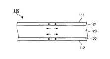
図2は、ガラス板10の残留応力の厚さ方向分布を示す模式図である。図2に示すように、表面層21や裏面層22に残留する圧縮応力は、表面11および裏面12から内部に向けて徐々に小さくなる傾向にある。また、中間層23に残留する引張応力は、ほぼ一定である。 FIG. 2 is a schematic diagram showing the thickness direction distribution of the residual stress of the
図2において、S1は表面層21の最大残留圧縮応力、S2は裏面層22の最大残留圧縮応力、D1は表面層21の厚さ、D2は裏面層22の厚さ、Dはガラス板10の厚さ、Tは中間層23の平均残留引張応力をそれぞれ示す。S1、S2(S2=S1)、D1、D2(D2=D1)、Tは、強化処理条件で調節可能であり、化学強化用の処理液の濃度や温度、化学強化用のガラスを処理液に浸漬する時間などにて調節可能である。また、S1、S2、D1、D2は市販の表面応力計などで測定可能であり、その測定結果およびDを下記の式(1)に代入して、Tは算出可能である。
T=(S1×D1/2+S2×D2/2)/(D−D1−D2)・・・(1)
Dはマイクロゲージなどで測定したデータを用いる。In FIG. 2, S1 is the maximum residual compressive stress of the
T = (S1 × D1 / 2 + S2 × D2 / 2) / (D−D1−D2) (1)
For D, data measured with a micro gauge or the like is used.
なお、本実施形態の表面層21と裏面層22は、同じ最大残留圧縮応力、同じ厚さを有するが、異なる最大残留引張応力、異なる厚さを有しても良い。 The
ガラス板10は、例えば図1に示すように、表面11と、裏面12と、切断面である側端面13〜16とを有する。 The
表面11および裏面12は、それぞれ、平坦面であって、化学強化用の処理液に浸漬された面である。表面11および裏面12は、それぞれ、例えば、矩形状に形成されている。ここで、「矩形状」とは、正方形状や長方形状をいい、コーナ部分が丸みを帯びた形状を含む。 Each of the
なお、表面11および裏面12の形状に制限はなく、例えば三角形状などの多角形状であっても良いし、円状や楕円状などであっても良い。 In addition, there is no restriction | limiting in the shape of the
側端面13〜16は、表面11および裏面12に対して略垂直に形成されている。そのため、側端面13〜16と表面11との境界線40と、側端面13〜16と裏面12との境界線とは、略同じ寸法形状を有する。 The side end surfaces 13 to 16 are formed substantially perpendicular to the
側端面13〜16は、例えば図1に示すように、平坦面であって良いが、湾曲面であっても良く、その形状に制限はない。なお、本実施形態では、側端面13〜16の全てが切断面であるが、側端面13〜16の少なくとも1つが切断面であれば良い。 The side end surfaces 13 to 16 may be flat surfaces as shown in FIG. 1, for example, but may be curved surfaces, and the shape thereof is not limited. In the present embodiment, all of the side end surfaces 13 to 16 are cut surfaces, but at least one of the side end surfaces 13 to 16 may be a cut surface.
次に、図1に基づいて、側端面13の構成について説明する。残りの側端面14〜16の構成は、側端面13の構成と同様であるので、説明を省略する。 Next, the configuration of the
側端面13は、図1に示すように、圧縮応力が残留する領域31、32と、引張応力が残留する領域33とを有する。 As shown in FIG. 1, the
圧縮応力が残留する領域31は表面層21の側端面で構成され、圧縮応力が残留する領域32は裏面層22の側端面で構成され、引張応力が残留する領域33は中間層23の側端面で構成されている。そのため、引張応力が残留する領域33は、圧縮応力が残留する2つの領域31、32の間に形成されている。 The
なお、側端面13の構成は、これに限定されない。例えば、側端面13に隣接する側端面14、16が切断面ではなく、化学強化用の処理液に浸漬された面である場合、側端面13において、引張応力が残留する領域は、圧縮応力が残留する領域によって四方を囲まれる。 In addition, the structure of the
本実施形態では、中間層23の平均残留引張応力Tが40MPaを超える。詳しくは後述するが、第2および第3の実施形態によれば、中間層23の平均残留引張応力Tが40MPaを超えるガラス板10を、化学強化後に切断して得ることができる。 In the present embodiment, the average residual tensile stress T of the intermediate layer 23 exceeds 40 MPa. Although mentioned later in detail, according to 2nd and 3rd embodiment, the
中間層23の平均残留引張応力Tが40MPaを超えるガラス板は、従来、切断後に化学強化してなるが、本実施形態では、化学強化後に切断してなるので、安価なガラス板が得られる。 Conventionally, a glass plate having an average residual tensile stress T of the intermediate layer 23 exceeding 40 MPa is chemically strengthened after cutting, but in this embodiment, it is cut after chemical strengthening, so that an inexpensive glass plate can be obtained.
また、中間層23の平均残留引張応力Tが40MPaを超えると、表面層21の最大残留圧縮応力S1および厚さD1、裏面層22の最大残留圧縮応力S2および厚さD2を所望の値以上とすることが可能であるので、良好な耐傷性が得られる。 Further, when the average residual tensile stress T of the intermediate layer 23 exceeds 40 MPa, the maximum residual compressive stress S1 and the thickness D1 of the
中間層23の平均残留引張応力Tは、好ましくは43MPa以上、より好ましくは46MPa以上である。中間層23の平均残留引張応力Tは、化学強化の処理効率の観点から、60MPa以下であって良い。 The average residual tensile stress T of the intermediate layer 23 is preferably 43 MPa or more, more preferably 46 MPa or more. The average residual tensile stress T of the intermediate layer 23 may be 60 MPa or less from the viewpoint of the processing efficiency of chemical strengthening.
表面層21および裏面層22の最大残留圧縮応力S1、S2は、ガラス板10の用途などに応じて適宜設定されるが、良好な耐傷性を得るため、例えば少なくとも一方が500MPa以上である。最大残留圧縮応力S1、S2は、それぞれ、化学強化の処理効率の観点から、900MPa以下であって良い。最大残留圧縮応力S1、S2は、それぞれ、好ましくは600〜900MPa、より好ましくは700〜900MPaである。 The maximum residual compressive stresses S1 and S2 of the
表面層21および裏面層22の厚さD1、D2は、ガラス板10の用途などに応じて適宜設定されるが、例えば少なくとも一方が20μm以上である。厚さD1、D2は、それぞれ、化学強化の処理効率の観点から、80μm以下であって良い。厚さD1、D2は、それぞれ、好ましくは30〜80μm、より好ましくは40〜80μmである。 Although thickness D1, D2 of the
ガラス板10の厚さは、ガラス板10の用途などに応じて適宜設定される。例えば、ガラス板10の厚さは、0.4〜1.8mmである。ガラス板10の厚さを0.4mm以上とすることで、ガラス板10の剛性を十分に高めることができる。一方で、ガラス板10の厚さを1.8mm以下とすることで、ガラス板10を十分に薄板化・軽量化することができる。ガラス板10の厚さは、好ましくは0.6〜1.2mm、より好ましくは0.7〜1.1mmである。 The thickness of the
ガラス板10の組成は、ガラス板10の用途に応じて選定される。例えば、化学強化前のガラス板10は、以下のような各成分の含有率が例示される。
(組成1:モル百分率表示)SiO2を50〜74%、Al2O3を1〜10%、Na2Oを6〜14%、K2Oを3〜15%、MgOを2〜15%、CaOを0〜10%、ZrO2を0〜5%含有し、SiO2およびAl2O3の含有量の合計が75%以下、Na2OおよびK2Oの含有量の合計Na2O+K2Oが12〜25%、MgOおよびCaOの含有量の合計MgO+CaOが7〜15%。
(組成2:モル百分率表示)SiO2を61〜66%、Al2O3を6〜12%、MgOを7〜13%、Na2Oを9〜17%、K2Oを0〜7%含有し、ZrO2を含有する場合その含有量が0.8%以下。
(組成3:質量百分率表示)SiO2を75.5〜85.5%、MgOを1〜8%、CaOを0〜7%、Al2O3を0〜5%、Na2Oを10〜22.5%を含有し、MgOの含有量がCaOの含有量より多く、MgOおよびCaOの含有量の合計(MgO+CaO)が8%以下、MgO、CaOおよびNa2Oの含有量の合計が24.5%以下、MgOおよびCaOの含有量(MgO+CaO)をNa2Oの含有量で除して得られた比が0.45以下。
化学強化用のガラスは、フロート法、フュージョンダウンドロー法、スリットダウンドロー法、リドロー法などで作製される。The composition of the
(Composition 1: expressed in mole percentage) SiO2 50-74%, Al2 O3 1-10%, Na2 O 6-14%, K2 O 3-15%, MgO 2-15% , CaO 0 to 10%, ZrO2 0 to 5%, the total content of SiO2 and Al2 O3 is 75% or less, the total content of Na2 O and K2 O Na2 O + K2 O is 12 to 25%, and the total content of MgO and CaO is 7 to 15%.
(Composition 2: mole percentage display) a SiO2 61 - 66%, theAl 2O 36~12%, the
(Composition 3: mass percentage) of SiO2 75.5~85.5%, the
The glass for chemical strengthening is produced by a float method, a fusion down draw method, a slit down draw method, a redraw method, or the like.
ガラス板10の用途は、特に限定されないが、例えば、携帯機器に組み込まれるディスプレイ用のカバーガラス、基板などであって良い。 Although the use of the
[第2の実施形態]
第2の実施形態は、上記のガラス板10を製造する方法に関し、特に、化学強化されたガラス板(以下、「化学強化ガラス板」という)を切断する方法に関する。[Second Embodiment]
The second embodiment relates to a method of manufacturing the
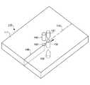
図3は、本発明の第2の実施形態に係るガラス板の製造方法の説明図である。 Drawing 3 is an explanatory view of the manufacturing method of the glass plate concerning a 2nd embodiment of the present invention.
ガラス板の製造方法は、化学強化ガラス板110の所定領域130に交番電界を印加することによって、所定領域130を徐冷点以下の温度で誘電加熱する工程を有する。加熱温度を徐冷点以下の温度としたのは、ガラスは徐冷点を超える温度に加熱されると、熱応力を緩和するように、粘性流動するからである。 The glass plate manufacturing method includes a step of dielectrically heating the
該工程において、化学強化ガラス板110の表面111上の切断予定線113に沿って所定領域130を移動させることで、化学強化ガラス板110を切断する。 In this step, the chemically strengthened
切断予定線113は、切断箇所となる予定の仮想線である。切断予定線113は、目的に応じた形状を有し、直線状部分、曲線状部分、または、両者の組み合わせで構成される。例えば、切断予定線113は、図3に示すように、1つの直線状部分で構成される。 The
切断予定線113の全体には、スクライブ線(溝線)が予め形成されていない。スクライブ線を予め形成しても良いが、この場合、工程数が増えるので、作業が繁雑である。また、スクライブ線を予め形成すると、ガラスが欠けることがある。 A scribe line (groove line) is not formed in advance on the
切断予定線113の始端は、化学強化ガラス板110の表面111の外周と交わっている。切断予定線113の始端およびその近傍には、切断の起点となる初期クラックが予め形成されている。初期クラックの形成方法は、一般的な方法であって良く、例えばカッタやヤスリ、レーザで形成される。工程数を削減するため、初期クラックは無くても良い。 The starting end of the planned
切断予定線113の終端は、化学強化ガラス板110の表面111の外周と交わっている。なお、切断予定線の終端は、切断予定線の途中と交わっていても良く、この場合、切断予定線は例えばP字状に設定される。 The end of the planned
化学強化ガラス板110の所定領域130に交番電界を印加するため、化学強化ガラス板110を介して、第1および第2の電極131、132が対向配置されている。 In order to apply an alternating electric field to the
第1および第2の電極131、132は、それぞれ、針状に形成されて良く、化学強化ガラス板110に向けて先細りの先端部を有して良い。これによって、交番電界を印加する所定領域130が狭窄され、切断精度が高くなる。 Each of the first and
第1および第2の電極131、132は、短くなるほど、リーク電流を低減でき、電力損失を低減できるが、一方で、ハンドリング性を悪化させる。第1および第2の電極131、132の長さは、電力損失とハンドリング性を考慮して決定され、例えば1〜300mmであり、好ましくは2〜100mm、より好ましくは3〜50mmである。 As the first and
第1および第2の電極131、132は、長さや電力に応じた平均直径を有する。平均直径は、例えば0.1〜20mmであり、好ましくは0.2〜10mm、より好ましくは0.4〜4mmである。 The first and
第1および第2の電極131、132は、化学強化ガラス板110から離間して配置されて良い。これによって、接触による損傷を防止することができる。また、これによって、第1および第2の電極131、132と、化学強化ガラス板110との間に放電が生じるので、加熱効率が向上する。 The first and
放電の安定化のため、第1および第2の電極131、132の周辺雰囲気は、窒素雰囲気やアルゴン雰囲気などの不活性雰囲気であることが好ましく、減圧雰囲気であることがより好ましい。 In order to stabilize discharge, the ambient atmosphere around the first and
第1および第2の電極131、132は、回路133を介して、電気的に接続されている。第2の電極132は、アースされていることが望ましい。 The first and
回路133は、第1の電極131に交流電流を印加する高周波電源134、第1の電極131に印加される交流電流の周波数やデューティ比、電圧を変調する変調器135などで構成される。 The
高周波電源134は、第1の電極131に交流電流を印加することによって、第1の電極131と、第2の電極132との間に交番電界を形成し、ひいては、所定領域130に交番電界を形成する。所定領域130は、交番電界によって誘電加熱される。 The high-
所定領域130の単位体積当たりの誘電加熱量Pは、P=ε0×εr×tanδ×2π×f×(V/t)2の式で表される。式中、ε0は真空の誘電率、εrは化学強化ガラス板110の比誘電率、δは誘電損失角、fは第1の電極131に印加される交流電流の周波数、Vは第1の電極131に印加される交流電圧、tは化学強化ガラス板110の厚さを示す。上記の式から明らかなように、誘電加熱量Pは、周波数fや交流電圧Vなどにて調節可能である。The dielectric heating amount P per unit volume of the
周波数fや交流電圧Vは、化学強化ガラス板110の切断速度などに応じて適宜設定される。周波数fは、例えば103〜1010Hzであって、好ましくは104〜109Hz、より好ましくは105〜108Hzである。交流電圧Vは、例えば10〜107Vであって、好ましくは102〜106V、より好ましくは102〜105Vである。The frequency f and the alternating voltage V are appropriately set according to the cutting speed of the chemically strengthened
本実施形態では、化学強化ガラス板110を誘電加熱するので、化学強化ガラス板110の表面層や裏面層だけでなく中間層を加熱することができる。そのため、化学強化ガラス板110の応力は、後述の図4に示す状態から、後述の図5や図6に示す状態に変化する。 In this embodiment, since the chemically strengthened
図4は、誘電加熱前の化学強化ガラス板110の断面における応力分布の説明図である。図4において、矢印の方向は、応力の作用方向を示し、矢印の長さは、応力の大きさを示す。 FIG. 4 is an explanatory diagram of the stress distribution in the cross section of the chemically strengthened
化学強化ガラス板110は、上記のガラス板10と同様に、圧縮応力が残留する表面層121および裏面層122を有し、表面層121と裏面層122との間には、引張応力が残留する中間層123が形成されている。表面層121や裏面層122の最大残留圧縮応力、厚さ、中間層123の平均残留引張応力、化学強化ガラス板110の厚さは、上記のガラス板10と略同じである。 Similarly to the
図5は、図3のA−A線に沿った断面図であって、所定領域130を含む断面図である。図6は、図3のB−B線に沿った断面図であって、図5に示す断面よりも後方の断面である。ここで、「後方」とは、所定領域130の移動方向後方を意味する。図5および図6において、矢印の方向は、応力の作用方向を示し、矢印の長さは、応力の大きさを示す。 FIG. 5 is a cross-sectional view taken along line AA in FIG. 3 and includes a
図5に示すように、所定領域130における中間層123では、誘電加熱によって温度が周辺に比べて高くなるので、図4に示す残留引張応力よりも小さい引張応力、または、圧縮応力が生じる。そのため、クラック140の伸展が阻害されている。クラック140の伸展を確実に防止するため、図5に示すように、圧縮応力が生じていることが好ましい。 As shown in FIG. 5, the
また、図5に示すように、所定領域130における表面層121や裏面層122では、誘電加熱によって温度が周辺に比べて高くなるので、図4に示す残留圧縮応力よりも大きい圧縮応力が生じている。そのため、クラック140の伸展が阻害されている。 Further, as shown in FIG. 5, in the
図5に示す応力との釣り合いのため、図5に示す断面よりも後方の断面では、図6に示すように、中間層123に引張応力が生じる。この引張応力は、図4に示す残留引張応力よりも大きく、引張応力が所定値に達している部分に、クラック140が形成される。このクラック140は、化学強化ガラス板110を表面111から裏面112まで貫通しており、本実施形態の切断は所謂フルカット切断である。 In order to balance with the stress shown in FIG. 5, tensile stress is generated in the
本発明者の知見によると、中間層123の平均残留引張応力が30MPa以上になると、中間層123の残留引張応力のみで、中間層123に形成されたクラックが自然に伸展する(自走する)。 According to the knowledge of the present inventor, when the average residual tensile stress of the
本実施形態では、中間層123の平均残留引張応力が40MPaを超えるので、引張応力が所定値に達する位置、即ち、クラック140の先端位置と、所定領域130との間の距離が十分に短くなるので、良好な切断精度が得られる。 In this embodiment, since the average residual tensile stress of the
図5および図6に示す状態で、化学強化ガラス板110の表面111上の切断予定線113に沿って、所定領域130を移動させると、所定領域130に追従するようにクラック140が伸展する。クラック140の先端は、所定領域130を追い越さない。 In the state shown in FIGS. 5 and 6, when the
なお、クラック140の先端は、所定領域130を追従するのでなく、所定領域130と重なるように移動してもよい。クラック140の先端が所定領域130に近いほど、切断精度が向上する。 Note that the tip of the
このように、本実施形態では、所定領域130における中間層123の残留引張応力が熱応力によって緩和されるので、クラック140が所定領域130を越えて伸展するのを防止できる。また、本実施形態では、所定領域130の後方近傍に残留引張応力よりも大きい引張応力が生じるので、クラック140が所定領域130の軌跡から外れるのを防止できる。従って、中間層123の平均残留引張応力が40MPaを超える場合にも、所望の寸法形状のガラス板10(図1参照)を得ることができる。 Thus, in this embodiment, since the residual tensile stress of the
所定領域130の移動は、化学強化ガラス板110に対する、第1および第2の電極131、132の相対的な移動によって行われる。所定領域130の移動は、化学強化ガラス板110の移動、または、第1および第2の電極131、132の移動によって実現され、これらの組合せで実現されても良い。 The movement of the
ガラス板の製造方法は、図7に示すように、化学強化ガラス板110の表面111に、ノズル150から冷媒を吹き付ける工程を有しても良い。冷媒としては、冷却空気などのガス、冷水などの液体が用いられる。ガスと液体を組み合わせて用いても良い。 As shown in FIG. 7, the glass plate manufacturing method may include a step of spraying a coolant from the
冷媒を吹き付ける領域160は、表面111において、上記の所定領域130の後方近傍に配され、上記の所定領域130に追従させる。これによって、所定領域130の後方近傍において、高い温度勾配が生じ、高い圧力勾配が生じるので、引張応力が所定値に達する位置、即ち、クラック140の先端位置と、所定領域130との間の距離が短くなる。よって、クラック140の位置制御性が高くなる。 The
なお、本実施形態では、交番電界の形成のため、第1および第2の電極131、132が用いられるとしたが、第2の電極132の代わりに、化学強化ガラス板110自身を用いても良い。この場合、化学強化ガラス板110と、第1の電極131とが回路133を介して電気的に接続される。この場合、化学強化ガラス板110はアースされていることが望ましい。 In the present embodiment, the first and
[第3の実施形態]
第3の実施形態は、上記のガラス板10を製造する方法に関し、特に、化学強化ガラス板を切断する方法に関する。[Third Embodiment]
3rd Embodiment is related with the method of manufacturing said
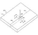
図8は、本発明の第3の実施形態に係るガラス板の製造方法の説明図である。 FIG. 8 is an explanatory diagram of the glass plate manufacturing method according to the third embodiment of the present invention.
ガラス板の製造方法は、化学強化ガラス板210の所定領域230にレーザ光232を照射することによって、所定領域230を徐冷点以下の温度で加熱する工程を有する。加熱温度を徐冷点以下の温度としたのは、ガラスは徐冷点を超える温度に加熱されると、熱応力を緩和するように、粘性流動するからである。 The manufacturing method of a glass plate has the process of heating the predetermined area |
該工程において、化学強化ガラス板210の表面211上の切断予定線213に沿って所定領域230を移動させることで、化学強化ガラス板210を切断する。 In this step, the chemically strengthened
切断予定線213は、切断箇所となる予定の仮想線であって、上記の第2の実施形態と同様に構成される。切断予定線213の全体には、スクライブ線(溝線)が予め形成されていなくて良い。切断予定線213の始端およびその近傍には、切断の起点となる初期クラックが予め形成されていて良い。 The
レーザ光232の光源としては、特に限定されないが、例えば、UVレーザ(波長:355nm)、グレーンレーザ(波長:532nm)、半導体レーザ(波長:808nm、940nm、975nm)、ファイバーレーザ(波長:1060〜1100nm)、YAGレーザ(波長:1064nm、2080nm、2940nm)などが挙げられる。光源の発振方式に制限はなく、レーザ光を連続発振するCWレーザ、レーザ光を断続発振するパルスレーザのいずれも使用可能である。また、レーザ光232の強度分布に制限はなく、ガウシアン型であっても、トップハット型であっても良い。 The light source of the
光源から出射されたレーザ光232は、集光レンズなどで集光され、化学強化ガラス板210の表面211に照射される。 The
レーザ光232の集光位置は、表面211を基準として、レーザ光232の光源側であっても良いし、裏面212側であっても良い。また、レーザ光232の集光位置は、化学強化ガラス板210の外部であっても良いし、内部であっても良い。 The condensing position of the
レーザ光232の光軸は、表面211において、例えば図8に示すように表面211と直交していても良いし、表面211と斜めに交わっていても良い。 The optical axis of the
本実施形態では、化学強化ガラス板210とレーザ光232とが、レーザ光232に対する化学強化ガラス板210の吸収係数をα(cm−1)とし、化学強化ガラス板210の厚さをt(cm)として、0<α×t≦3.0の式を満たす。In the present embodiment, the chemically strengthened
化学強化ガラス板210に入射する前のレーザ光232の強度をI0とし、化学強化ガラス板210中を距離w(cm)だけ移動したときのレーザ光232の強度をIとすると、I=I0×exp(−α×w)の式が成立する。Assuming that the intensity of the
α×tを0より大きく3.0以下とすることで、化学強化ガラス板210内でのレーザ光232の強度が十分に高くなり、レーザ光232が化学強化ガラス板210の表面層だけでなく、中間層や裏面層を十分に加熱できる。その結果、化学強化ガラス板210に生じる応力は、後述の図9に示す状態から、後述の図10や図11に示す状態に変化する。 By making α × t greater than 0 and 3.0 or less, the intensity of the
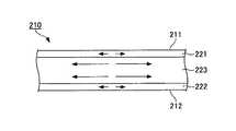
図9は、レーザ加熱前の化学強化ガラス板210の断面における応力分布の説明図である。図9において、矢印の方向は、応力の作用方向を示し、矢印の長さは、応力の大きさを示す。 FIG. 9 is an explanatory diagram of the stress distribution in the cross section of the chemically strengthened
図9に示すように、レーザ加熱前の化学強化ガラス板210は、上記のガラス板10と同様に、圧縮応力が残留する表面層221および裏面層222を有し、表面層221と裏面層222との間には、引張応力が残留する中間層223が形成されている。表面層221や裏面層222の最大残留圧縮応力、厚さ、中間層223の平均残留引張応力、化学強化ガラス板210の厚さは、上記のガラス板10と略同じである。 As shown in FIG. 9, the chemically strengthened
図10は、図8のA−A線に沿った断面図であって、所定領域230を含む断面図である。図11は、図8のB−B線に沿った断面図であって、図9に示す断面よりも後方の断面である。ここで、「後方」とは、所定領域230の移動方向後方を意味する。図10および図11において、矢印の方向は、応力の作用方向を示し、矢印の長さは、応力の大きさを示す。 FIG. 10 is a cross-sectional view taken along the line AA in FIG. 8 and includes a
図10に示すように、所定領域230における中間層223では、レーザ光232によって温度が周辺に比べて高くなるので、図9に示す残留引張応力よりも小さい引張応力、または、圧縮応力が生じる。そのため、クラック240の伸展が阻害されている。クラック240の伸展を確実に防止するため、図10に示すように、圧縮応力が生じていることが好ましい。 As shown in FIG. 10, in the
また、図10に示すように、所定領域230における表面層221や裏面層222では、レーザ加熱によって温度が周辺に比べて高くなるので、図9に示す残留圧縮応力よりも大きい圧縮応力が生じている。そのため、クラック240の伸展が阻害されている。 Further, as shown in FIG. 10, the
図10に示す応力との釣り合いのため、図10に示す断面よりも後方の断面では、図11に示すように、中間層223に引張応力が生じる。この引張応力は、図9に示す残留引張応力よりも大きく、引張応力が所定値に達している部分に、クラック240が形成される。このクラック240は、化学強化ガラス板210を表面211から裏面212まで貫通しており、本実施形態の切断は所謂フルカット切断である。 In order to balance the stress shown in FIG. 10, a tensile stress is generated in the
本発明者の知見によると、中間層223の平均残留引張応力が30MPa以上になると、中間層223の残留引張応力のみで、中間層223に形成されたクラックが自然に伸展する(自走する)。 According to the knowledge of the present inventor, when the average residual tensile stress of the
本実施形態では、中間層223の平均残留引張応力が40MPaを超えるので、引張応力が所定値に達する位置、即ち、クラック240の先端位置と、所定領域230との間の距離が十分に短くなるので、良好な切断精度が得られる。 In the present embodiment, since the average residual tensile stress of the
図10および図11に示す状態で、化学強化ガラス板210の表面211上の切断予定線213に沿って、所定領域230を移動させると、所定領域230に追従するようにクラック240が伸展する。クラック240の先端は、所定領域230を追い越さない。 In the state shown in FIGS. 10 and 11, when the
なお、クラック240の先端は、所定領域230を追従するのでなく、所定領域230と重なるように移動してもよい。クラック240の先端が所定領域230に近いほど、切断精度が向上する。 Note that the tip of the
このように、本実施形態では、所定領域230における中間層223の残留引張応力が熱応力によって緩和されるので、クラック240が所定領域230を越えて伸展するのを防止できる。また、本実施形態では、所定領域230の後方近傍に残留引張応力よりも大きい引張応力が生じるので、クラック240が所定領域230の軌跡から外れるのを防止できる。従って、中間層223の平均残留引張応力が40MPaを超える場合にも、所定領域230を越えてクラック240が伸展しないので、所望の寸法形状のガラス板10(図1参照)を得ることができる。 Thus, in this embodiment, since the residual tensile stress of the
所定領域230の移動は、化学強化ガラス板210に対する、レーザ光232の相対的な移動によって行われる。所定領域230の移動は、化学強化ガラス板210の移動、レーザ光232の光源の移動、またはレーザ光232の光路の途中に設けられるミラーの回転によって実現され、これらの組合せで実現されても良い。 The movement of the
ガラスは、用途によっては、高い透明度が要求されるので、使用レーザ波長が可視光の波長領域に近い場合はα×tは0に近いほど良い。しかし、α×tは、小さすぎると吸収効率が悪くなるので、好ましくは0.0005以上(レーザ光吸収率0.05%以上)、より好ましくは0.002以上(レーザ光吸収率0.2%以上)、さらに好ましくは0.004以上(レーザ光吸収率0.4%以上)である。 Since high transparency is required for glass depending on the application, α × t is preferably closer to 0 when the laser wavelength used is close to the wavelength region of visible light. However, since α × t is too small, the absorption efficiency is deteriorated. Therefore, it is preferably 0.0005 or more (laser light absorption rate 0.05% or more), more preferably 0.002 or more (laser light absorption rate 0.2 % Or more), more preferably 0.004 or more (laser light absorption rate 0.4% or more).
ガラスは、用途によっては、逆に低い透明度が要求されるので、使用レーザ波長が可視光の波長領域に近い場合はα×tは大きいほど良い。しかし、α×tが大きすぎると表面吸収が大きくなるのでクラック伸展を制御できなくなる。このため、α×tは、好ましくは3.0以下(レーザ光吸収率95%以下)、より好ましくは0.1以下(レーザ光吸収率10%以下)、さらに好ましくは0.02以下(レーザ光吸収率2%以下)である。 Glass, on the other hand, requires low transparency, so that when the used laser wavelength is close to the wavelength region of visible light, the larger α × t is better. However, if α × t is too large, surface absorption increases, and crack extension cannot be controlled. Therefore, α × t is preferably 3.0 or less (laser light absorptivity 95% or less), more preferably 0.1 or less (
吸収係数αは、レーザ光232の波長、化学強化ガラス板210のガラス組成などで定まる。例えば、化学強化ガラス板210中の酸化鉄(FeO、Fe2O3、Fe3O4を含む)の含有量、酸化コバルト(CoO、Co2O3、Co3O4を含む)の含有量、酸化銅(CuO、Cu2Oを含む)の含有量が多くなるほど、1000nm付近の近赤外線波長領域での吸収係数αが大きくなる。さらに、化学強化ガラス板210中の希土類元素(例えばYb)の酸化物の含有量が多くなるほど、希土類原子の吸収波長付近で吸収係数αが大きくなる。The absorption coefficient α is determined by the wavelength of the
化学強化ガラス板210中の酸化鉄の含有量は、化学強化ガラス板210を構成するガラスの種類によるが、ソーダライムガラスの場合、例えば0.02〜1.0質量%である。この範囲で、酸化鉄の含有量を調節することで、1000nm付近の近赤外線波長領域でのα×tを所望の範囲に調節可能である。酸化鉄の含有量を調節する代わりに、酸化コバルトや酸化銅、希土類元素の酸化物の含有量を調節しても良い。 The content of iron oxide in the chemically strengthened
1000nm付近の近赤外線波長領域での吸収係数αは、用途に応じて設定され、例えば自動車用窓ガラスの場合、3cm−1以下、建築用窓ガラスの場合、0.6cm−1以下、ディスプレイ用ガラスの場合、0.2cm−1以下であることが好ましい。The absorption coefficient α in the near-infrared wavelength region near 1000 nm is set according to the application. For example, in the case of an automotive window glass, 3 cm−1 or less, in the case of an architectural window glass, 0.6 cm−1 or less, for display In the case of glass, it is preferably 0.2 cm−1 or less.
レーザ光232の波長は、250〜3000nmであることが好ましい。レーザ光232の波長を250〜3000nmとすることで、レーザ光232の透過率と、レーザ光232による加熱効率とを両立できる。レーザ光232の波長は、より好ましくは300〜2000nm、さらに好ましくは800〜1500nmである。 The wavelength of the
所定領域230は、表面(レーザ光入射面)211において、直径Φの円形状に形成されて良く、この場合、直径Φは、切断精度やレーザパワーを考慮して決定される。直径Φが小さくなるほど、切断予定線213の始端や終端付近での切断精度が高くなるが、一方で、レーザ光のパワー密度が高くなり、切断面が荒れて微細な亀裂が形成されることがある。直径Φは、例えば、0.18mmよりも大きく、1.03mmよりも小さく設定される。切断予定線213の全体に亘る切断精度を高めるため、直径Φは、0.5mm以下であることが好ましい。 The
なお、所定領域230は、表面211上において、矩形状、楕円状などに形成されても良く、その形状に制限はない。 The
ガラス板の製造方法は、図12に示すように、化学強化ガラス板210の表面211に、ノズル250から冷媒を吹き付ける工程を有しても良い。冷媒としては、冷却空気などのガス、冷水などの液体が用いられる。ガスと液体を組み合わせて用いても良い。 As shown in FIG. 12, the glass plate manufacturing method may include a step of spraying a coolant from the
冷媒を吹き付ける領域260は、表面211において、所定領域230の後方近傍に配され、所定領域230に追従させる。これによって、所定領域230の後方近傍において、高い温度勾配が生じ、高い圧力勾配が生じるので、引張応力が所定値に達する位置、即ち、クラック240の先端位置と、所定領域230との間の距離が短くなる。よって、クラック240の位置制御性が高くなる。 The
以下に、実施例などにより本発明を具体的に説明するが、本発明はこれらの例によって限定されるものではない。 EXAMPLES The present invention will be specifically described below with reference to examples, but the present invention is not limited to these examples.
[例1]
(化学強化ガラス板の作製)
化学強化用のガラスとしては、縦100mm×横120mm×厚さ0.7mmの平板ガラスを用意した。平板ガラスは、質量%表示で、SiO2:64.5%、Al2O3:6.0%、MgO:11.0%、Na2O:12.0%、K2O:4%、ZrO2:2.5%を含有していた。[Example 1]
(Production of chemically strengthened glass plate)
As the glass for chemical strengthening, a flat glass having a length of 100 mm × width of 120 mm × thickness of 0.7 mm was prepared. The flat glass is expressed by mass%, SiO2 : 64.5%, Al2 O3 : 6.0%, MgO: 11.0%, Na2 O: 12.0%, K2 O: 4%, ZrO2 : contained 2.5%.
化学強化ガラス板は、用意した平板ガラスを、KNO3溶融塩に浸漬し、イオン交換処理した後、室温付近まで冷却することにより作製した。KNO3溶融塩の温度は425℃とし、浸漬時間は5.5時間とした。The chemically strengthened glass plate was prepared by immersing the prepared flat glass in KNO3 molten salt, performing an ion exchange treatment, and then cooling to near room temperature. The temperature of the KNO3 molten salt was 425 ° C., and the immersion time was 5.5 hours.
化学強化された表面層の最大残留圧縮応力および厚さ、ならびに化学強化された裏面層の最大残留圧縮応力および厚さは、表面応力計(折原製作所製、FSM−6000LE)によって測定した。また、中間層の平均残留引張応力は、表面応力計の測定結果などを上記の式(1)に代入して算出した。 The maximum residual compressive stress and thickness of the chemically strengthened surface layer and the maximum residual compressive stress and thickness of the chemically strengthened back layer were measured by a surface stress meter (FSM-6000LE, manufactured by Orihara Seisakusho). Moreover, the average residual tensile stress of the intermediate layer was calculated by substituting the measurement result of the surface stress meter into the above formula (1).
測定の結果、化学強化された表面層と裏面層とは、同じ最大残留圧縮応力(720MPa)、同じ厚さ(39μm)を有していた。また、中間層の平均残留引張応力は、45MPaであった。 As a result of the measurement, the chemically strengthened surface layer and the back surface layer had the same maximum residual compressive stress (720 MPa) and the same thickness (39 μm). The average residual tensile stress of the intermediate layer was 45 MPa.
(化学強化ガラス板の切断)
化学強化ガラス板の切断は、図3に示す切断方法で行った。(Cut the chemically strengthened glass plate)
The chemically tempered glass plate was cut by the cutting method shown in FIG.
化学強化ガラス板の表面上の切断予定線は、1つの直線状部分で構成した。直線状部分は、表面の外周の一辺と平行であって、該一辺との間の距離は10mmとした。 The planned cutting line on the surface of the chemically strengthened glass plate was composed of one linear portion. The straight portion was parallel to one side of the outer periphery of the surface, and the distance between the one side was 10 mm.
切断前に、切断予定線の全体に亘るスクライブ線は形成されず、切断予定線の始端およびその近傍には、切断の基点となる初期クラックがヤスリで形成された。 Prior to the cutting, a scribe line covering the entire planned cutting line was not formed, and an initial crack serving as a base point for cutting was formed by a file at the starting end of the planned cutting line and in the vicinity thereof.
化学強化ガラス板の所定領域に交番電界を印加するため、第1の電極に印加する電力は20W、周波数は15MHzとした。上記所定領域は、切断予定線の始端から終端まで40mm/secの速度で移動させた。 In order to apply an alternating electric field to a predetermined region of the chemically strengthened glass plate, the power applied to the first electrode was 20 W, and the frequency was 15 MHz. The predetermined area was moved at a speed of 40 mm / sec from the start end to the end of the planned cutting line.
(切断後のガラス板の評価)
切断の結果、所望の寸法形状(縦100mm×横60mm×厚さ0.7mm)のガラス板を得ることができた。切断面である側端面と表面との境界線は、切断予定線と同一寸法形状であって、直線状部分のみを有していた。得られたガラス板について下記の評価を行った。(Evaluation of glass plate after cutting)
As a result of cutting, a glass plate having a desired size and shape (length 100 mm × width 60 mm × thickness 0.7 mm) could be obtained. The boundary line between the side end surface, which is a cut surface, and the surface has the same size and shape as the planned cutting line, and has only a linear portion. The following evaluation was performed about the obtained glass plate.
切断後の表面層の最大残留圧縮応力および厚さ、ならびに切断後の裏面層の最大残留圧縮応力および厚さは、上記の方法で測定した。また、中間層の平均残留引張応力は、上記の式(1)に基づいて算出した。 The maximum residual compressive stress and thickness of the surface layer after cutting, and the maximum residual compressive stress and thickness of the back layer after cutting were measured by the above methods. Moreover, the average residual tensile stress of the intermediate layer was calculated based on the above formula (1).
切断後のガラス板の50%破壊荷重(50% fracture load)は、ガラス表面に正四角錐状のビッカース圧子(ダイヤモンド圧子)を押し込むことによって、50%の確率でガラスが破壊される押込荷重である。50%破壊荷重が大きいほど、耐傷性が高いことを意味する。 The 50% fracture load of the glass plate after cutting is an indentation load at which glass is broken with a probability of 50% by pushing a square pyramid-shaped Vickers indenter (diamond indenter) into the glass surface. . A larger 50% breaking load means higher scratch resistance.
評価結果を表1に示す。なお、表面層と裏面層とは、同じ最大残留圧縮応力、同じ厚さを示したので、表1には、表面層のデータのみ示す。 The evaluation results are shown in Table 1. Since the surface layer and the back surface layer showed the same maximum residual compressive stress and the same thickness, Table 1 shows only the data of the surface layer.
[例2]
化学強化ガラス板の作製は、KNO3溶融塩の温度は425℃とし、浸漬時間は6時間とした他は、例1と同様にして行った。[Example 2]
The chemically strengthened glass plate was produced in the same manner as in Example 1 except that the temperature of the KNO3 molten salt was 425 ° C. and the immersion time was 6 hours.
化学強化された表面層と裏面層とは、同じ最大残留圧縮応力(749MPa)、同じ厚さ(40μm)を有していた。また、中間層の平均残留引張応力は、48MPaであった。 The chemically strengthened front and back layers had the same maximum residual compressive stress (749 MPa) and the same thickness (40 μm). The average residual tensile stress of the intermediate layer was 48 MPa.
化学強化ガラス板の切断は、電力20W、周波数を15MHzとし、ガラスの表面上での所定領域の移動速度を40mm/secとした他は、例1と同様にして行った。 The chemically strengthened glass plate was cut in the same manner as in Example 1 except that the power was 20 W, the frequency was 15 MHz, and the moving speed of the predetermined region on the glass surface was 40 mm / sec.
切断の結果、所望の寸法形状(縦100mm×横60mm×厚さ0.7mm)のガラス板を得ることができた。切断面である側端面と表面との境界線は、切断予定線と同一寸法形状であって、直線状部分のみを有していた。 As a result of cutting, a glass plate having a desired size and shape (length 100 mm × width 60 mm × thickness 0.7 mm) could be obtained. The boundary line between the side end surface, which is a cut surface, and the surface has the same size and shape as the planned cutting line, and has only a linear portion.
得られたガラス板の評価結果を表1に示す。なお、表面層と裏面層とは、同じ最大残留圧縮応力、同じ厚さを示したので、表1には、表面層のデータのみ示す。 The evaluation results of the obtained glass plate are shown in Table 1. Since the surface layer and the back surface layer showed the same maximum residual compressive stress and the same thickness, Table 1 shows only the data of the surface layer.
[例3]
化学強化ガラス板の作製は、KNO3溶融塩の温度は425℃とし、浸漬時間は5時間とした他は、例1と同様にして行った。[Example 3]
The chemically strengthened glass plate was produced in the same manner as in Example 1 except that the temperature of the KNO3 molten salt was 425 ° C. and the immersion time was 5 hours.
化学強化された表面層と裏面層とは、同じ最大残留圧縮応力(700MPa)、同じ厚さ(37μm)を有していた。また、中間層の平均残留引張応力は、41MPaであった。 The chemically strengthened surface layer and the back surface layer had the same maximum residual compressive stress (700 MPa) and the same thickness (37 μm). The average residual tensile stress of the intermediate layer was 41 MPa.
化学強化ガラス板の切断は、電力は20W、周波数を15MHzとし、ガラスの表面上での所定領域の移動速度を30mm/secとした他は、例1と同様にして行った。 The chemically tempered glass plate was cut in the same manner as in Example 1 except that the power was 20 W, the frequency was 15 MHz, and the moving speed of the predetermined region on the surface of the glass was 30 mm / sec.
切断の結果、所望の寸法形状(縦100mm×横60mm×厚さ1.1mm)のガラス板を得ることができた。切断面である側端面と表面との境界線は、切断予定線と同一寸法形状であって、直線状部分のみを有していた。 As a result of cutting, a glass plate having a desired size and shape (length 100 mm × width 60 mm × thickness 1.1 mm) could be obtained. The boundary line between the side end surface, which is a cut surface, and the surface has the same size and shape as the planned cutting line, and has only a linear portion.
得られたガラス板の評価結果を表1に示す。なお、表面層と裏面層とは、同じ最大残留圧縮応力、同じ厚さを示したので、表1には、表面層のデータのみ示す。 The evaluation results of the obtained glass plate are shown in Table 1. Since the surface layer and the back surface layer showed the same maximum residual compressive stress and the same thickness, Table 1 shows only the data of the surface layer.
[例4]
化学強化用のガラスとしては、縦100mm×横120mm×厚さ1.4mmの平板ガラスを用意した。化学強化ガラス板の作製は、KNO3溶融塩の温度は450℃とし、浸漬時間は10時間とした他は、例1と同様にして行った。[Example 4]
As glass for chemical strengthening, flat glass having a length of 100 mm, a width of 120 mm, and a thickness of 1.4 mm was prepared. The chemically strengthened glass plate was produced in the same manner as in Example 1 except that the temperature of the KNO3 molten salt was 450 ° C. and the immersion time was 10 hours.
化学強化された表面層と裏面層とは、同じ最大残留圧縮応力(785MPa)、同じ厚さ(70μm)を有していた。また、中間層の平均残留引張応力は、43.6MPaであった。 The chemically strengthened front and back layers had the same maximum residual compressive stress (785 MPa) and the same thickness (70 μm). Moreover, the average residual tensile stress of the intermediate layer was 43.6 MPa.
化学強化ガラス板の切断は、図3に示す切断方法の代わりに、図8に示す切断方法を用いた他は、例1と同様にして行った。 The chemically tempered glass plate was cut in the same manner as in Example 1 except that the cutting method shown in FIG. 8 was used instead of the cutting method shown in FIG.
化学強化ガラス板の所定領域に照射されるレーザ光の光源としては、ファイバーレーザ(波長帯:1075〜1095nm)を用いた。レーザ光に対する化学強化ガラス板の吸収係数αは、紫外可視近赤外分光光度計Lambda950によって測定したところ、0.48cm−1であり、化学強化ガラス板の厚さt(cm)との積α×tが0.0672であった。A fiber laser (wavelength band: 1075 to 1095 nm) was used as a light source of laser light irradiated to a predetermined region of the chemically strengthened glass plate. The absorption coefficient α of the chemically strengthened glass plate with respect to laser light is 0.48 cm−1 as measured by an ultraviolet-visible near-infrared spectrophotometer Lambda 950, and the product α with the thickness t (cm) of the chemically strengthened glass plate. Xt was 0.0672.
所定領域は、化学強化ガラス板の表面上において、直径0.3mmの円形状に形成され、レーザ出力を50Wとし、切断予定線の始端(初期クラック)から終端まで10mm/secの速度で移動させた。 The predetermined area is formed in a circular shape with a diameter of 0.3 mm on the surface of the chemically strengthened glass plate, the laser output is 50 W, and the predetermined area is moved from the start end (initial crack) to the end of the planned cutting line at a speed of 10 mm / sec. It was.
切断の結果、所望の寸法形状(縦100mm×横60mm×厚さ1.4mm)のガラス板を得ることができた。切断面である側端面と表面との境界線は、切断予定線と同一寸法形状であって、直線状部分のみを有していた。 As a result of cutting, a glass plate having a desired size and shape (length 100 mm × width 60 mm × thickness 1.4 mm) could be obtained. The boundary line between the side end surface, which is a cut surface, and the surface has the same size and shape as the planned cutting line, and has only a linear portion.
得られたガラス板の評価結果を表1に示す。なお、表面層と裏面層とは、同じ最大残留圧縮応力、同じ厚さを示したので、表1には、表面層のデータのみ示す。 The evaluation results of the obtained glass plate are shown in Table 1. Since the surface layer and the back surface layer showed the same maximum residual compressive stress and the same thickness, Table 1 shows only the data of the surface layer.
[例5]
化学強化ガラス板の作製は、KNO3溶融塩の温度は400℃とし、浸漬時間は1時間とした他は、例1と同様にして行った。[Example 5]
The chemically strengthened glass plate was produced in the same manner as in Example 1 except that the temperature of the KNO3 molten salt was 400 ° C. and the immersion time was 1 hour.
化学強化された表面層と裏面層とは、同じ最大残留圧縮応力(696MPa)、同じ厚さ(19μm)を有していた。また、中間層の平均残留引張応力は、20MPaであった。 The chemically strengthened front and back layers had the same maximum residual compressive stress (696 MPa) and the same thickness (19 μm). The average residual tensile stress of the intermediate layer was 20 MPa.
化学強化ガラス板の切断は、電力は20W、周波数を15MHzとし、ガラスの表面上での所定領域の移動速度を40mm/secとした他は、例1と同様にして行った。 The chemically tempered glass plate was cut in the same manner as in Example 1 except that the power was 20 W, the frequency was 15 MHz, and the moving speed of the predetermined region on the glass surface was 40 mm / sec.
切断の結果、所望の寸法形状(縦100mm×横60mm×厚さ0.7mm)のガラス板を得ることができた。切断面である側端面と表面との境界線は、切断予定線と同一寸法形状であって、直線状部分のみを有していた。 As a result of cutting, a glass plate having a desired size and shape (length 100 mm × width 60 mm × thickness 0.7 mm) could be obtained. The boundary line between the side end surface, which is a cut surface, and the surface has the same size and shape as the planned cutting line, and has only a linear portion.
得られたガラス板の評価結果を表1に示す。なお、表面層と裏面層とは、同じ最大残留圧縮応力、同じ厚さを示したので、表1には、表面層のデータのみ示す。 The evaluation results of the obtained glass plate are shown in Table 1. Since the surface layer and the back surface layer showed the same maximum residual compressive stress and the same thickness, Table 1 shows only the data of the surface layer.
[例6]
化学強化用のガラスとしては、縦100mm×横120mm×厚さ0.5mmの平板ガラスを用意した。化学強化ガラス板の作製は、KNO3溶融塩の温度は425℃とし、浸漬時間は5.5時間とした他は、例1と同様にして行った。[Example 6]
As the glass for chemical strengthening, a flat glass having a length of 100 mm × width of 120 mm × thickness of 0.5 mm was prepared. The chemically strengthened glass plate was produced in the same manner as in Example 1 except that the temperature of the KNO3 molten salt was 425 ° C. and the immersion time was 5.5 hours.
化学強化された表面層と裏面層とは、同じ最大残留圧縮応力(583MPa)、同じ厚さ(37μm)を有していた。また、中間層の平均残留引張応力は、46.7MPaであった。 The chemically strengthened front and back layers had the same maximum residual compressive stress (583 MPa) and the same thickness (37 μm). The average residual tensile stress of the intermediate layer was 46.7 MPa.
化学強化ガラス板の切断は、レーザ光の光源として、ファイバーレーザ(波長帯:1075〜1095nm)の代わりに、炭酸ガスレーザ(波長:10600nm)を用いた他は、例6と同様にして行った。 The chemically strengthened glass plate was cut in the same manner as in Example 6 except that a carbon dioxide laser (wavelength: 10600 nm) was used instead of the fiber laser (wavelength band: 1075 to 1095 nm) as the light source of the laser beam.
レーザ光に対する化学強化ガラス板の吸収係数αは、紫外可視近赤外分光光度計Lambda950によって予め測定したところ、1000cm−1を超えており、化学強化ガラス板の厚さt(cm)との積α×tが50を超えていた。The absorption coefficient α of the chemically strengthened glass plate with respect to the laser light is measured in advance with an ultraviolet-visible-near-infrared spectrophotometer Lambda 950 and exceeds 1000 cm−1 , which is a product of the thickness t (cm) of the chemically strengthened glass plate. α × t exceeded 50.
所定領域は、化学強化ガラス板の表面上において、移動方向に長い楕円状(長さ12mm、幅3mm)に形成され、レーザ出力を30Wとし、切断予定線の始端(初期クラック)から終端まで10mm/secの速度で移動させた。移動方向に長い楕円状としたのは、同じ場所を長時間加熱することで、表面が瞬間的に過熱されるのを抑制すると共に、表面から内部への熱伝達を促し、内部を加熱するためである。 The predetermined region is formed in an elliptical shape (length 12 mm, width 3 mm) long in the moving direction on the surface of the chemically strengthened glass plate, the laser output is 30 W, and 10 mm from the start edge (initial crack) to the end of the planned cutting line. It was moved at a speed of / sec. The long oval shape in the moving direction is to heat the same place for a long time, to suppress the surface from being overheated momentarily and to promote the heat transfer from the surface to the inside, thereby heating the inside. It is.
しかし、レーザ光の大部分が化学強化ガラス板の表面近傍で吸収され、表面近傍が加熱されたため、切断時に形成されるクラックが所定領域を越えて伸展し、ガラスが粉砕されてしまった。なお、表1における記号「N/A」は、切断時にガラスが粉砕されたため、50%破壊荷重を評価できなかったことを表す。 However, most of the laser light was absorbed near the surface of the chemically strengthened glass plate and the vicinity of the surface was heated, so that cracks formed during cutting extended beyond a predetermined region, and the glass was crushed. Note that the symbol “N / A” in Table 1 indicates that the 50% breaking load could not be evaluated because the glass was crushed during cutting.

10 ガラス板
11 表面
12 裏面
13 側端面
21 表面層
22 裏面層
23 中間層
31 圧縮応力が残留する領域
32 圧縮応力が残留する領域
33 引張応力が残留する領域
110 化学強化ガラス板
111 表面
113 切断予定線
130 所定領域
210 化学強化ガラス板
211 表面
213 切断予定線
230 所定領域
232 レーザ光DESCRIPTION OF
Claims (6)
Translated fromJapanese前記中間層の平均残留引張応力が40MPaを超えることを特徴とするガラス板。It is a cut surface having a surface layer and a back surface layer that are cut after chemical strengthening and in which compressive stress remains, and an intermediate layer that is formed between the surface layer and the back surface layer and in which tensile stress remains. In the glass plate having a region where compressive stress remains and a region where tensile stress remains on the side end face,
An average residual tensile stress of the intermediate layer exceeds 40 MPa.
化学強化ガラス板の所定領域に交番電界を印加することによって、前記所定領域を徐冷点以下の温度で誘電加熱する工程を有し、
該工程において、前記化学強化ガラス板の表面上の切断予定線に沿って前記所定領域を移動させることで、前記化学強化ガラス板を切断するガラス板の製造方法。It is a method of manufacturing the glass plate of any one of Claims 1-4,
By applying an alternating electric field to a predetermined region of the chemically strengthened glass plate, and subjecting the predetermined region to dielectric heating at a temperature below the annealing point,
The manufacturing method of the glass plate which cut | disconnects the said chemically strengthened glass plate in this process by moving the said predetermined area | region along the cutting projected line on the surface of the said chemically strengthened glass plate.
前記化学強化ガラス板の所定領域にレーザ光を照射することによって、前記所定領域を徐冷点以下の温度で加熱する工程を有し、
該工程において、前記化学強化ガラス板の表面上の切断予定線に沿って前記所定領域を移動させることで、前記化学強化ガラス板を切断し、
前記化学強化ガラス板と前記レーザ光は、前記レーザ光に対する前記化学強化ガラス板の吸収係数をα(cm−1)とし、前記化学強化ガラス板の厚さをt(cm)とすると、0<α×t≦3の式を満たすガラス板の製造方法。It is a method of manufacturing the glass plate of any one of Claims 1-4,
Irradiating the predetermined region of the chemically strengthened glass plate with a laser beam to heat the predetermined region at a temperature below the annealing point;
In this step, by moving the predetermined region along the planned cutting line on the surface of the chemically strengthened glass plate, the chemically strengthened glass plate is cut,
The chemical tempered glass plate and the laser beam have an absorption coefficient of α (cm−1 ) for the laser beam and α (cm−1 ), and the thickness of the chemically tempered glass plate is t (cm). A method for producing a glass plate satisfying the formula of α × t ≦ 3.
Priority Applications (1)
| Application Number | Priority Date | Filing Date | Title |
|---|---|---|---|
| JP2011059847AJP2012193092A (en) | 2011-03-17 | 2011-03-17 | Glass plate and method for producing the same |
Applications Claiming Priority (1)
| Application Number | Priority Date | Filing Date | Title |
|---|---|---|---|
| JP2011059847AJP2012193092A (en) | 2011-03-17 | 2011-03-17 | Glass plate and method for producing the same |
Publications (1)
| Publication Number | Publication Date |
|---|---|
| JP2012193092Atrue JP2012193092A (en) | 2012-10-11 |
Family
ID=47085375
Family Applications (1)
| Application Number | Title | Priority Date | Filing Date |
|---|---|---|---|
| JP2011059847AWithdrawnJP2012193092A (en) | 2011-03-17 | 2011-03-17 | Glass plate and method for producing the same |
Country Status (1)
| Country | Link |
|---|---|
| JP (1) | JP2012193092A (en) |
Cited By (2)
| Publication number | Priority date | Publication date | Assignee | Title |
|---|---|---|---|---|
| JP2016503386A (en)* | 2012-11-21 | 2016-02-04 | コーニング インコーポレイテッド | Cutting method of laminated tempered glass substrate |
| WO2018066314A1 (en)* | 2016-10-07 | 2018-04-12 | 日本電気硝子株式会社 | Method for manufacturing reinforced glass plate, film-coated glass plate, and reinforced glass plate |
Citations (10)
| Publication number | Priority date | Publication date | Assignee | Title |
|---|---|---|---|---|
| JP2001192240A (en)* | 2000-10-30 | 2001-07-17 | Seiko Instruments Inc | Display device and method for manufacturing the same |
| JP2006256944A (en)* | 2005-03-14 | 2006-09-28 | Lemi Ltd | Method and device for cutting brittle material |
| JP2007055072A (en)* | 2005-08-24 | 2007-03-08 | Lemi Ltd | Method and apparatus for high-frequency heating/cutting based on dielectric loss of brittle material |
| JP2008007360A (en)* | 2006-06-28 | 2008-01-17 | Optrex Corp | Mother glass substrate, glass substrate and method for manufacturing the glass substrate |
| WO2008108332A1 (en)* | 2007-03-02 | 2008-09-12 | Nippon Electric Glass Co., Ltd. | Reinforced plate glass and method for manufacturing the same |
| JP2008260642A (en)* | 2007-04-10 | 2008-10-30 | Nh Techno Glass Kk | Glass composition, glass plate using the same, and method for producing the same |
| WO2009019965A1 (en)* | 2007-08-03 | 2009-02-12 | Nippon Electric Glass Co., Ltd. | Hardened glass substrate and method for manufacturing the same |
| JP2009040665A (en)* | 2007-08-12 | 2009-02-26 | Lemi Ltd | Full body cutting method of brittle material |
| JP2009107301A (en)* | 2007-10-31 | 2009-05-21 | Lemi Ltd | Full body cutting method for brittle material |
| JP2010070445A (en)* | 2008-08-18 | 2010-04-02 | Nippon Electric Glass Co Ltd | Method for manufacturing glass for touch panel |
- 2011
- 2011-03-17JPJP2011059847Apatent/JP2012193092A/ennot_activeWithdrawn
Patent Citations (11)
| Publication number | Priority date | Publication date | Assignee | Title |
|---|---|---|---|---|
| JP2001192240A (en)* | 2000-10-30 | 2001-07-17 | Seiko Instruments Inc | Display device and method for manufacturing the same |
| JP2006256944A (en)* | 2005-03-14 | 2006-09-28 | Lemi Ltd | Method and device for cutting brittle material |
| JP2007055072A (en)* | 2005-08-24 | 2007-03-08 | Lemi Ltd | Method and apparatus for high-frequency heating/cutting based on dielectric loss of brittle material |
| JP2008007360A (en)* | 2006-06-28 | 2008-01-17 | Optrex Corp | Mother glass substrate, glass substrate and method for manufacturing the glass substrate |
| WO2008108332A1 (en)* | 2007-03-02 | 2008-09-12 | Nippon Electric Glass Co., Ltd. | Reinforced plate glass and method for manufacturing the same |
| JP2008247732A (en)* | 2007-03-02 | 2008-10-16 | Nippon Electric Glass Co Ltd | Reinforced plate glass and method for manufacturing the same |
| JP2008260642A (en)* | 2007-04-10 | 2008-10-30 | Nh Techno Glass Kk | Glass composition, glass plate using the same, and method for producing the same |
| WO2009019965A1 (en)* | 2007-08-03 | 2009-02-12 | Nippon Electric Glass Co., Ltd. | Hardened glass substrate and method for manufacturing the same |
| JP2009040665A (en)* | 2007-08-12 | 2009-02-26 | Lemi Ltd | Full body cutting method of brittle material |
| JP2009107301A (en)* | 2007-10-31 | 2009-05-21 | Lemi Ltd | Full body cutting method for brittle material |
| JP2010070445A (en)* | 2008-08-18 | 2010-04-02 | Nippon Electric Glass Co Ltd | Method for manufacturing glass for touch panel |
Cited By (2)
| Publication number | Priority date | Publication date | Assignee | Title |
|---|---|---|---|---|
| JP2016503386A (en)* | 2012-11-21 | 2016-02-04 | コーニング インコーポレイテッド | Cutting method of laminated tempered glass substrate |
| WO2018066314A1 (en)* | 2016-10-07 | 2018-04-12 | 日本電気硝子株式会社 | Method for manufacturing reinforced glass plate, film-coated glass plate, and reinforced glass plate |
Similar Documents
| Publication | Publication Date | Title |
|---|---|---|
| JP5431583B2 (en) | Cutting method of tempered glass sheet | |
| WO2013031655A1 (en) | Cutting method for reinforced glass plate and reinforced glass plate cutting device | |
| WO2013031778A1 (en) | Cutting method for reinforced glass plate and reinforced glass plate cutting device | |
| US8607590B2 (en) | Methods for separating glass articles from strengthened glass substrate sheets | |
| WO2012172960A1 (en) | Method for cutting glass plate | |
| KR102082672B1 (en) | Method for cutting toughened glass plate | |
| EP2922794B1 (en) | Method of cutting a laminate strengthened glass substrate | |
| TWI428300B (en) | Method for separating stiffening glass | |
| JP2013035721A (en) | Method for producing glass plate, and chemically strengthened glass for display device | |
| US20120135177A1 (en) | Methods for forming grooves and separating strengthened glass substrate sheets | |
| JP2013043808A (en) | Holder for tempered glass plate cutting, and method for cutting tempered glass plate | |
| JP2013203630A (en) | Method for cutting tempered glass plate | |
| JP2011251879A (en) | Method and device for cutting chemically strengthened glass | |
| KR20150037816A (en) | Method for cutting tempered glass plate | |
| US20130192305A1 (en) | Methods for separating glass substrate sheets by laser-formed grooves | |
| CN110128008A (en) | Low ultra-thin strengthened glass of radius of curvature and preparation method thereof, glass devices and element glass | |
| WO2013011877A1 (en) | Plate glass, manufacturing method therefor, and device for manufacturing said plate glass | |
| JP2012193093A (en) | Glass plate and method for producing the same | |
| WO2012118083A1 (en) | Cutting method for glass plate member, and cutting device | |
| EP4509688A2 (en) | Vacum insulated glass unit with getter, and method of activating a getter in vacuum insulated glass unit | |
| JP2012193092A (en) | Glass plate and method for producing the same | |
| JP2013053019A (en) | Method for boring tempered glass | |
| JP2012193091A (en) | Glass plate and method for producing the same | |
| JP2012193090A (en) | Glass plate and method for producing the same | |
| WO2013031771A1 (en) | Method for cutting reinforced glass |
Legal Events
| Date | Code | Title | Description |
|---|---|---|---|
| A621 | Written request for application examination | Free format text:JAPANESE INTERMEDIATE CODE: A621 Effective date:20130902 | |
| A977 | Report on retrieval | Free format text:JAPANESE INTERMEDIATE CODE: A971007 Effective date:20140331 | |
| A131 | Notification of reasons for refusal | Free format text:JAPANESE INTERMEDIATE CODE: A131 Effective date:20140408 | |
| A761 | Written withdrawal of application | Free format text:JAPANESE INTERMEDIATE CODE: A761 Effective date:20140514 |