JP2012192242A - Handheld electrosurgical instrument having disable handswitch - Google Patents
Handheld electrosurgical instrument having disable handswitchDownload PDFInfo
- Publication number
- JP2012192242A JP2012192242AJP2012155479AJP2012155479AJP2012192242AJP 2012192242 AJP2012192242 AJP 2012192242AJP 2012155479 AJP2012155479 AJP 2012155479AJP 2012155479 AJP2012155479 AJP 2012155479AJP 2012192242 AJP2012192242 AJP 2012192242A
- Authority
- JP
- Japan
- Prior art keywords
- switch
- forceps
- electrosurgical
- lockout
- tissue
- Prior art date
- Legal status (The legal status is an assumption and is not a legal conclusion. Google has not performed a legal analysis and makes no representation as to the accuracy of the status listed.)
- Pending
Links
Images


Classifications
- A—HUMAN NECESSITIES
- A61—MEDICAL OR VETERINARY SCIENCE; HYGIENE
- A61B—DIAGNOSIS; SURGERY; IDENTIFICATION
- A61B18/00—Surgical instruments, devices or methods for transferring non-mechanical forms of energy to or from the body
- A61B18/04—Surgical instruments, devices or methods for transferring non-mechanical forms of energy to or from the body by heating
- A61B18/12—Surgical instruments, devices or methods for transferring non-mechanical forms of energy to or from the body by heating by passing a current through the tissue to be heated, e.g. high-frequency current
- A61B18/14—Probes or electrodes therefor
- A61B18/1442—Probes having pivoting end effectors, e.g. forceps
- A—HUMAN NECESSITIES
- A61—MEDICAL OR VETERINARY SCIENCE; HYGIENE
- A61B—DIAGNOSIS; SURGERY; IDENTIFICATION
- A61B18/00—Surgical instruments, devices or methods for transferring non-mechanical forms of energy to or from the body
- A61B2018/00571—Surgical instruments, devices or methods for transferring non-mechanical forms of energy to or from the body for achieving a particular surgical effect
- A61B2018/0063—Sealing
- A—HUMAN NECESSITIES
- A61—MEDICAL OR VETERINARY SCIENCE; HYGIENE
- A61B—DIAGNOSIS; SURGERY; IDENTIFICATION
- A61B18/00—Surgical instruments, devices or methods for transferring non-mechanical forms of energy to or from the body
- A61B2018/0091—Handpieces of the surgical instrument or device
- A61B2018/00916—Handpieces of the surgical instrument or device with means for switching or controlling the main function of the instrument or device
- A61B2018/00922—Handpieces of the surgical instrument or device with means for switching or controlling the main function of the instrument or device by switching or controlling the treatment energy directly within the hand-piece
Landscapes
- Health & Medical Sciences (AREA)
- Surgery (AREA)
- Engineering & Computer Science (AREA)
- Life Sciences & Earth Sciences (AREA)
- Biomedical Technology (AREA)
- Otolaryngology (AREA)
- Nuclear Medicine, Radiotherapy & Molecular Imaging (AREA)
- Plasma & Fusion (AREA)
- Physics & Mathematics (AREA)
- Heart & Thoracic Surgery (AREA)
- Medical Informatics (AREA)
- Molecular Biology (AREA)
- Animal Behavior & Ethology (AREA)
- General Health & Medical Sciences (AREA)
- Public Health (AREA)
- Veterinary Medicine (AREA)
- Surgical Instruments (AREA)
Abstract
Description
Translated fromJapanese (背景)
(技術分野)
本開示は、ハンドヘルド電気外科器具のハンドスイッチを働かないようにするシステムおよび方法に関する。より特定すれば、本開示は、代表的には、ハンドヘルド器具に電気外科エネルギーの選択的印加を可能するような形態である、ハンドスイッチを働かないようにするための電気的配列および機械的配列に関する。(background)
(Technical field)
The present disclosure relates to systems and methods for disabling hand switches of handheld electrosurgical instruments. More particularly, the present disclosure provides an electrical and mechanical arrangement for disabling the hand switch, typically configured to allow selective application of electrosurgical energy to a handheld instrument. About.
(関連技術の背景)
エネルギーを基礎にした組織処理は当該技術分野で周知である。種々のタイプのエネルギー(例えば、電気、超音波、マイクロ波、低温、熱、レーザーなど)が、組織に印加され得、所望の外科的結果を達成する。電気手術は、代表的には、手術部位への高周波電流の付与を含み、組織を切断、切除(ablate)、凝固またはシールする。単極電気手術では、電源または能動電極が、高周波エネルギーを電気外科電源から組織まで送達し、そして戻り電極が、この電流を電源に運んで戻す。単極電気手術では、供給源電極は、代表的には、使用者によって保持される外科用器具の一部であって、そして処置されるべき組織に適用される。患者の戻り電極は、能動電極から遠隔に配置され、電流を電源に運んで戻す。(Background of related technology)
Energy-based tissue processing is well known in the art. Various types of energy (eg, electricity, ultrasound, microwave, low temperature, heat, laser, etc.) can be applied to the tissue to achieve the desired surgical result. Electrosurgery typically involves the application of a high frequency current to the surgical site to cut, ablate, coagulate or seal the tissue. In monopolar electrosurgery, a power source or active electrode delivers radio frequency energy from the electrosurgical power source to the tissue, and a return electrode carries this current back to the power source. In monopolar electrosurgery, the source electrode is typically part of a surgical instrument held by the user and applied to the tissue to be treated. The patient's return electrode is located remotely from the active electrode and carries current back to the power source.
双極電気手術では、ハンドヘルド器具の電極の1つが能動電極として、そして他方が戻り電極として機能する。この戻り電極は、能動電極に、これら2つの電極(例えば、電気外科鉗子)に間に電気回路が形成されるように緊密に近接して配置される。このようにして、印加された電流は、電極間に位置決めされる身体組織に制限される。これらの電極が互いから十分に分離されるとき、上記電気回路は開いており、そしてそれ故、身体組織といずれかの分離された電極との不注意な接触は電流を流さない。 In bipolar electrosurgery, one of the electrodes of the handheld instrument functions as the active electrode and the other as the return electrode. The return electrode is placed in close proximity to the active electrode so that an electrical circuit is formed between the two electrodes (eg, electrosurgical forceps). In this way, the applied current is limited to the body tissue positioned between the electrodes. When these electrodes are sufficiently separated from each other, the electrical circuit is open, and therefore inadvertent contact between body tissue and any of the separated electrodes does not conduct current.
単極切断器具、双極電気外科鉗子など、種々のタイプの器具が、電気外科手順を実施するために利用され、これらは、内視鏡的または開放使用のいずれかのためにさらに適合される。これらの器具の多くは、複数スイッチング配列(例えば、ハンドスイッチ、フットスイッチなど)を含み、これらは、上記器具への電気外科エネルギーの流れを起動する。手術の間に、上記器具が所望の組織部位に位置決めされると、使用者は、上記スイッチング配列を起動する。この目的のために、上記ハンドスイッチは、通常、選択的起動を容易にする大きな容易に接近可能なボタンを含む。電気外科エネルギーの不注意の供給を防ぐために、ハンドヘルド電気外科器具のハンドスイッチを働かないようにし得るシステムおよび方法に対する必要性が存在する。 Various types of instruments are utilized to perform electrosurgical procedures, such as monopolar cutting instruments, bipolar electrosurgical forceps, which are further adapted for either endoscopic or open use. Many of these instruments include multiple switching arrangements (eg, hand switches, foot switches, etc.) that activate the flow of electrosurgical energy to the instruments. During surgery, when the instrument is positioned at the desired tissue site, the user activates the switching arrangement. For this purpose, the hand switch typically includes a large easily accessible button that facilitates selective activation. To prevent inadvertent delivery of electrosurgical energy, there is a need for systems and methods that can prevent the handswitch of a handheld electrosurgical instrument from working.
(要旨)
本開示は、ハンドヘルド電気外科器具のハンドスイッチを働かないようにするためのシステムおよび方法に関する。詳細には、本開示は、ハンドスイッチを働かないようにする機械的形態、電気的形態、および電気−機械的形態を提供する。(Summary)
The present disclosure relates to systems and methods for disabling hand switches of handheld electrosurgical instruments. Specifically, the present disclosure provides mechanical, electrical, and electro-mechanical forms that prevent the hand switch from working.
本開示の1つの局面によれば、組織をシールするための電気外科鉗子が開示される。この鉗子は、少なくとも1つのハンドルを備え、このハンドルはそれに取り付けられた少なくとも1つのシャフト部材を有する。この少なくとも1つのシャフト部材は、その遠位端に取り付けられた端部エフェクターを有する。この端部エフェクターは、互いに対して間隔を置いた関係にある第1の位置から、顎部材がそれらの間に組織を握るために協働する少なくとも1つの位置まで移動可能である一対の顎部材を含む。これら顎部材の各々は、それらの間に保持された組織を通って電気外科エネルギーを伝達し、組織シールを行うための電気的に伝導性のシールプレートを含み、これら電気的に伝導性のシールプレートは、電気外科電源に接続するように適合されている。この鉗子はまた、上記少なくとも1つのハンドルおよび上記少なくとも1つのシャフト部材の少なくとも1つに作動可能に連結されたハンドスイッチを含む。このハンドスイッチは、この電気外科電源に接続するよう適合され、そして上記鉗子の電気外科起動を開始するよう選択的に起動可能である。この鉗子はさらに、上記少なくとも1つのハンドルおよび上記少なくとも1つのシャフト部材の少なくとも1つに作動可能に連結されるロックアウトスイッチを含む。このロックアウトスイッチは、このロックアウトスイッチが上記ハンドスイッチの起動を可能にする第1の形態から、このロックアウトスイッチが上記ハンドスイッチの起動および上記鉗子の起動を防ぐ第2の形態まで移動可能である。 According to one aspect of the present disclosure, an electrosurgical forceps for sealing tissue is disclosed. The forceps includes at least one handle that has at least one shaft member attached thereto. The at least one shaft member has an end effector attached to its distal end. The end effector is movable from a first position in spaced relation to each other to a pair of jaw members from which the jaw members cooperate to grasp tissue therebetween. including. Each of these jaw members includes an electrically conductive seal plate for transmitting electrosurgical energy through the tissue held between them and performing a tissue seal, the electrically conductive seals. The plate is adapted to connect to an electrosurgical power source. The forceps also includes a hand switch operatively coupled to at least one of the at least one handle and the at least one shaft member. The hand switch is adapted to connect to the electrosurgical power source and is selectively activatable to initiate electrosurgical activation of the forceps. The forceps further includes a lockout switch operatively coupled to at least one of the at least one handle and the at least one shaft member. The lockout switch is movable from a first configuration in which the lockout switch allows the hand switch to be activated to a second configuration in which the lockout switch prevents the activation of the hand switch and the forceps. It is.
本開示はまた、組織をシールするための電気外科鉗子の別の実施形態に関する。この鉗子は、少なくとも1つのハンドルであって、それに取り付けられた少なくとも1つのシャフト部材を有する。この少なくとも1つのシャフト部材は、その遠位端に取り付けられた端部エフェクターを有する。この端部エフェクターは1対の顎部材を含み、この顎部材は、互いに対して間隔を置いた第1の位置から、この顎部材がそれらの間に組織を握るために協働する少なくとも1つの次の位置まで移動可能である。この顎部材の各々は、電気的に伝導性のシールプレートを含み、このシールプレートは、組織シールを行うためにそれらの間に保持された組織を通って電気外科エネルギーを伝達し、これら電気的に伝導性のシールプレートは、電気外科電源に接続するように適合されている。上記鉗子はまた、上記少なくとも1つのハンドルおよび上記少なくとも1つのシャフト部材の少なくとも1つに作動可能に連結されたハンドスイッチを含む。このハンドスイッチは、上記電気外科電源に接続されるよう適合され、そして上記鉗子の電気外科起動の開始を選択的に起動可能である。上記鉗子はさらに、上記少なくとも1つのハンドルおよび上記少なくとも1つのシャフト部材の少なくとも1つに作動可能に連結されるロックアウトスイッチを含む。このロックアウトスイッチは、上記ハンドスイッチと、上記ロックアウトスイッチおよび上記ハンドスイッチの両方が上記鉗子の起動を可能にするために電気的に閉鎖されなければならないような電気的伝達にある形態である。 The present disclosure also relates to another embodiment of an electrosurgical forceps for sealing tissue. The forceps is at least one handle and has at least one shaft member attached thereto. The at least one shaft member has an end effector attached to its distal end. The end effector includes a pair of jaw members, the jaw members from a first position spaced relative to each other, the jaw members cooperating to grasp tissue therebetween. It can move to the next position. Each of the jaw members includes an electrically conductive seal plate that transmits electrosurgical energy through the tissue held between them to effect a tissue seal. The electrically conductive seal plate is adapted to connect to an electrosurgical power source. The forceps also includes a hand switch operably coupled to at least one of the at least one handle and the at least one shaft member. The hand switch is adapted to be connected to the electrosurgical power source and can selectively activate the initiation of electrosurgical activation of the forceps. The forceps further includes a lockout switch operably coupled to at least one of the at least one handle and the at least one shaft member. The lockout switch is in a form that is in electrical communication such that the hand switch and both the lockout switch and the hand switch must be electrically closed to allow activation of the forceps. .
本開示の別の局面によれば、組織をシールするための開放電気外科鉗子の別の実施形態が開示される。この鉗子は、少なくとも1つのハンドルであって、それに取り付けられた少なくとも1つのシャフト部材を有する少なくとも1つのハンドルを備える。この少なくとも1つのシャフト部材は、その遠位端に取り付けられた端部エフェクターを有する。この端部エフェクターは、互いに対して間隔を置いた第1の位置から、顎部材がそれらの間に組織を握るために協働する少なくとも1つの次の位置まで移動可能である1対の顎部材を含む。この顎部材の各々は、それらの間に保持された組織を通って電気外科エネルギーを伝達し組織シールを行うための電気的に伝導性のシールプレートを含み、この電気的に伝導性のシールプレートは電気外科電源に接続するように適合されている。これら鉗子はまた、上記少なくとも1つのハンドルおよび上記少なくとも1つのシャフト部材の少なくとも1つに作動可能に連結されるハンドスイッチを含む。このハンドスイッチは、上記電気外科電源に接続するように適合され、そして上記鉗子の電気外科起動を開始するために選択的に起動可能である。上記鉗子はさらに、少なくとも1つのラチェッインターフェースに作動可能に連結されるロックアウトスイッチを含む。このロックアウトスイッチは、上記ラチェットが該ハンドスイッチの起動を防ぐ互いとの間隔を置いた非作動係合に配置される第1の形態、およびこのラチェットが上記ハンドスイッチの起動および上記鉗子の起動を可能にする互いと作動可能に係合される第2の形態を含む。 According to another aspect of the present disclosure, another embodiment of an open electrosurgical forceps for sealing tissue is disclosed. The forceps includes at least one handle having at least one handle and having at least one shaft member attached thereto. The at least one shaft member has an end effector attached to its distal end. The end effector is movable from a first position spaced relative to each other to a pair of jaw members from which the jaw members cooperate to grasp tissue therebetween. including. Each of the jaw members includes an electrically conductive seal plate for transmitting electrosurgical energy and performing a tissue seal through the tissue held therebetween, the electrically conductive seal plate Is adapted to connect to an electrosurgical power source. The forceps also includes a hand switch operably coupled to at least one of the at least one handle and the at least one shaft member. The hand switch is adapted to connect to the electrosurgical power source and is selectively activatable to initiate electrosurgical activation of the forceps. The forceps further includes a lockout switch operably coupled to the at least one ratchet interface. The lockout switch has a first configuration in which the ratchet is disposed in a non-actuated engagement spaced apart from each other to prevent activation of the hand switch, and the ratchet activates the hand switch and the forceps. A second configuration operably engaged with each other.
上記に加えて、本発明は、以下を提供する:
(項目1)組織をシールするための電気外科鉗子であって:
少なくとも1つのハンドルであって、それに取り付けられた少なくとも1つのシャフト部材を有し、該少なくとも1つのシャフト部材がその遠位端に取り付けられた端部エフェクターを有し、該端部エフェクターが1対の顎部材を有し、該1対の顎部材が、互いに対して間隔を置いた関係にある第1の位置から、該顎部材がそれらの間に組織を握るために協働する少なくとも1つの次の位置に移動可能であり、該顎部材の各々が電気的に伝導性のシールプレートを含み、該シールプレートの間に保持された組織を通って電気外科エネルギーを伝達して組織シールを行い、該電気的に伝導性のシールプレートが電気外科電源に接続されるよう適合されるハンドル;
該少なくとも1つのハンドルおよび該少なくとも1つのシャフト部材の少なくとも1つに作動可能に連結されたハンドスイッチであって、該電気外科電源に接続されるよう適合され、該鉗子の電気外科起動を開始するために選択的に起動可能であるハンドスイッチ;および
該少なくとも1つのハンドルおよび該少なくとも1つのシャフト部材の少なくとも1つに作動可能に連結されるロックアウトスイッチであって、該ロックアウトスイッチが該ハンドスイッチの起動を可能にする第1の形態から、該ロックアウトスイッチが該ハンドスイッチの起動および該鉗子の起動を防ぐ第2の形態まで移動可能であるロックアウトスイッチ、を備える、電気外科鉗子。
(項目2)上記ハンドスイッチがトグルスイッチであり、そして上記ロックアウトスイッチが該トグルスイッチの押し下げを防ぐ、項目1に記載の電気外科鉗子。
(項目3)上記ロックアウトスイッチが、ロックアウトバーおよびそれから横方向に延びる起動ノブを含み、該起動ノブが第1のシャフトから突出するような寸法である、項目2に記載の電気外科鉗子。
(項目4)上記ロックアウトバーが、U形状ロックである、項目3に記載の電気外科鉗子。
(項目5)上記トグルスイッチが、トグルプレート、回路板およびそれらの間に配置されたスイッチボタンを含む、項目2に記載の電気外科鉗子。
(項目6)ロックする形態にある上記ロックアウトスイッチが、上記トグルプレートと上記スイッチボタンとの間に少なくとも部分的に配置され、該スイッチボタンの押し下げを防ぐ、項目5に記載の電気外科鉗子。
(項目7)上記ロックアウトスイッチが選択的にスライド可能であり、上記ハンドスイッチの起動を防ぐ、項目1に記載の電気外科鉗子。
(項目8)上記ロックアウトスイッチが、電気的に絶縁性の材料から作製される、項目1に記載の電気外科鉗子。
(項目9)組織をシールするための電気外科鉗子であって:
少なくとも1つのハンドルであって、それに取り付けられた少なくとも1つのシャフト部材を有し、該少なくとも1つのシャフト部材がその遠位端に取り付けられた端部エフェクターを有し、該端部エフェクターが1対の顎部材を含み、該顎部材が、互いに対して間隔を置いた第1の位置から、該顎部材がそれらの間に組織を握るために協働する少なくとも1つの次の位置まで移動可能であり、該顎部材の各々が電気的に伝導性のシールプレートを含み、該シールプレートが組織シールを行うためにそれらの間に保持された組織を通って電気外科エネルギーを伝達し、該電気的に伝導性のシールプレートが電気外科電源に接続するように適合されるハンドル;
該少なくとも1つのハンドルおよび該少なくとも1つのシャフト部材の少なくとも1つに作動可能に連結されたハンドスイッチであって、該電気外科電源に接続されるよう適合され、該鉗子の電気外科起動を開始するために選択的に起動可能であるハンドスイッチ;および
該少なくとも1つのハンドルおよび該少なくとも1つのシャフト部材の少なくとも1つに作動可能に連結されるロックアウトスイッチであって、該ロックアウトスイッチが、該ハンドスイッチと、該ロックアウトスイッチおよび該ハンドスイッチの両方が該鉗子の起動を可能にするために電気的に閉鎖されなければならないような電気的伝達にある形態であるロックアウトスイッチ、を備える、電気外科鉗子。
(項目10)上記少なくとも1つのハンドルおよび上記少なくとも1つのシャフト部材の少なくとも1つに作動可能に連結される第2のロックアウトスイッチをさらに備え、該ロックアウトスイッチが、該ロックアウトスイッチが上記ハンドスイッチの起動を可能にする第1の形態から、該ロックアウトスイッチが該ハンドスイッチの起動および上記鉗子の起動を防ぐ第2の形態まで移動可能である、項目9に記載の電気外科鉗子。
(項目11)上記ハンドスイッチがトグルスイッチであり、そして上記第2のロックアウトスイッチが該トグルスイッチの押し下げを防ぐ、項目10に記載の電気外科鉗子。
(項目12)上記第2のロックアウトスイッチが、ロックアウトバーおよびそれから横方向に延びる起動ノブを含み、該起動ノブが第1のシャフトから突出するような寸法である、項目10に記載の電気外科鉗子。
(項目13)上記第2のロックアウトスイッチが選択的にスライド可能であり、上記ハンドスイッチの起動を防ぐ、項目10に記載の電気外科鉗子。
(項目14)上記第2のロックアウトスイッチが、電気的に絶縁性の材料から作製される、項目10に記載の電気外科鉗子。
(項目15)組織をシールするための開放電気外科鉗子であって:
1対の第1のハンドルおよび第2のハンドルであって、該ハンドルの各々がその遠位端に配置された顎部材およびその近位端にあるラチェットインターフェースを有するシャフト部材を含み、該顎部材が、互いに対して間隔を置いた第1の位置から、該顎部材がそれらの間に組織を握るために協働する少なくとも1つの次の位置まで、該ハンドルの作動を経由して選択的に移動可能であり、該顎部材の各々がそれらの間に保持された組織を通って電気外科エネルギーを伝達し組織シールを行うための電気的に伝導性のシールプレートを含み、該電気的に伝導性のシールプレートが電気外科電源に接続するように適合されるハンドル;
該第1および第2のハンドルならびに該シャフト部材の少なくとも1つに作動可能にレ連結されるハンドスイッチであって、該電気外科電源に接続するように適合され、該鉗子の電気外科起動を開始するために選択的に起動可能であるハンドスイッチ;および
少なくとも1つのラチェットインターフェースに作動可能に連結されるロックアウトスイッチであって、該ラチェットが該ハンドスイッチの起動を防ぐ互いとの間隔を置いた非作動係合に配置される第1の形態、および該ラチェットが該ハンドスイッチの起動および該鉗子の起動を可能にする互いと作動可能に係合される第2の形態を有するロックアウトスイッチ、を備える、電気外科鉗子。
(項目16)上記少なくとも1つのハンドルおよび上記少なくとも1つのシャフト部材の少なくとも1つに作動可能に連結される第2のロックアウトスイッチをさらに備え、該ロックアウトスイッチが、該ロックアウトスイッチが上記ハンドスイッチの起動を可能にする第1の形態から、該ロックアウトスイッチが該ハンドスイッチの起動および上記鉗子の起動を防ぐ第2の形態まで移動可能である、項目15に記載の電気外科鉗子。
(項目17)上記ハンドスイッチがトグルスイッチであり、そして上記第2のロックアウトスイッチが該トグルスイッチの押し下げを防ぐ、項目16に記載の電気外科鉗子。
(項目18)上記第2のロックアウトスイッチが、ロックアウトバーおよびそれから横方向に延びる起動ノブを含み、該起動ノブが第1のシャフトから突出するような寸法である、項目16に記載の電気外科鉗子。
(項目19)上記第2のロックアウトスイッチが選択的にスライド可能であり、上記ハンドスイッチの起動を防ぐ、項目16に記載の電気外科鉗子。
(項目20)上記第2のロックアウトスイッチが、電気的に絶縁性の材料から作製される、項目16に記載の電気外科鉗子。In addition to the above, the present invention provides the following:
(Item 1) Electrosurgical forceps for sealing tissue:
At least one handle having at least one shaft member attached thereto, the at least one shaft member having an end effector attached to its distal end, the end effector being a pair At least one jaw member from a first position in spaced relation to each other, wherein the pair of jaw members cooperate to grasp tissue therebetween. Each of the jaw members includes an electrically conductive seal plate, and transmits electrosurgical energy through tissue held between the seal plates to effect tissue sealing. A handle adapted to connect the electrically conductive sealing plate to an electrosurgical power source;
A hand switch operably coupled to at least one of the at least one handle and the at least one shaft member, adapted to be connected to the electrosurgical power source and initiating electrosurgical activation of the forceps A hand switch that is selectively activatable for: a lockout switch operatively coupled to at least one of the at least one handle and the at least one shaft member, the lockout switch being the hand An electrosurgical forceps comprising a lockout switch that is movable from a first configuration that allows switch activation to a second configuration that prevents activation of the handswitch and activation of the forceps from the first configuration.
(Item 2) The electrosurgical forceps according to item 1, wherein the hand switch is a toggle switch, and the lockout switch prevents the toggle switch from being depressed.
3. The electrosurgical forceps according to claim 2, wherein the lockout switch includes a lockout bar and an activation knob extending laterally therefrom, the dimension of the activation knob protruding from the first shaft.
(Item 4) The electrosurgical forceps according to item 3, wherein the lockout bar is a U-shaped lock.
(Item 5) The electrosurgical forceps according to item 2, wherein the toggle switch includes a toggle plate, a circuit board, and a switch button disposed therebetween.
(Item 6) The electrosurgical forceps according to item 5, wherein the lockout switch in a locking configuration is disposed at least partially between the toggle plate and the switch button to prevent the switch button from being depressed.
(Item 7) The electrosurgical forceps according to item 1, wherein the lockout switch is selectively slidable to prevent activation of the hand switch.
(Item 8) The electrosurgical forceps according to item 1, wherein the lockout switch is made of an electrically insulating material.
(Item 9) Electrosurgical forceps for sealing tissue, wherein:
At least one handle having at least one shaft member attached thereto, the at least one shaft member having an end effector attached to its distal end, the end effector being a pair The jaw members are movable from a first position spaced relative to each other to at least one next position in which the jaw members cooperate to grasp tissue therebetween. Each of the jaw members includes an electrically conductive seal plate, wherein the seal plate transmits electrosurgical energy through tissue held therebetween to effect tissue sealing, and the electrical member A handle having a conductive sealing plate adapted to connect to an electrosurgical power source;
A hand switch operably coupled to at least one of the at least one handle and the at least one shaft member, adapted to be connected to the electrosurgical power source and initiating electrosurgical activation of the forceps A hand switch that is selectively activatable for: a lockout switch operably coupled to at least one of the at least one handle and the at least one shaft member, the lockout switch comprising: A hand switch and a lockout switch that is in a form that is in electrical communication such that both the lockout switch and the handswitch must be electrically closed to allow activation of the forceps, Electrosurgical forceps.
10. The method of
(Item 11) The electrosurgical forceps according to
12. The electrical power of
(Item 13) The electrosurgical forceps according to
(Item 14) The electrosurgical forceps according to
(Item 15) An open electrosurgical forceps for sealing tissue, comprising:
A pair of first and second handles, each including a shaft member having a jaw member disposed at its distal end and a ratchet interface at its proximal end, the jaw member Selectively via a actuation of the handle from a first position spaced relative to each other to at least one next position where the jaw members cooperate to grasp tissue therebetween. Each of the jaw members is movable and includes an electrically conductive seal plate for transmitting electrosurgical energy through the tissue held therebetween to effect tissue sealing, the electrically conductive A handle adapted to connect the sexual seal plate to an electrosurgical power source;
A hand switch operably coupled to at least one of the first and second handles and the shaft member, adapted to connect to the electrosurgical power source and initiating electrosurgical activation of the forceps A hand switch that is selectively activatable to: and a lockout switch operatively coupled to at least one ratchet interface, the ratchet spaced apart from each other to prevent activation of the hand switch A lockout switch having a first configuration disposed in non-actuating engagement and a second configuration in which the ratchet is operatively engaged with each other to enable activation of the hand switch and activation of the forceps; An electrosurgical forceps comprising:
16. The method of
(Item 17) The electrosurgical forceps according to item 16, wherein the hand switch is a toggle switch, and the second lockout switch prevents the toggle switch from being depressed.
18. The electrical power of claim 16, wherein the second lockout switch includes a lockout bar and an activation knob extending laterally therefrom and is dimensioned such that the activation knob protrudes from the first shaft. Surgical forceps.
(Item 19) The electrosurgical forceps according to item 16, wherein the second lockout switch is selectively slidable to prevent activation of the hand switch.
(Item 20) The electrosurgical forceps according to item 16, wherein the second lockout switch is made of an electrically insulating material.
本発明はまた、以下の項目を提供する。 The present invention also provides the following items.
(項目1) 組織をシールするための電気外科鉗子であって:
少なくとも1つのハンドルであって、それに取り付けられた少なくとも1つのシャフト部材を有し、その少なくとも1つのシャフト部材がその遠位端に取り付けられた端部エフェクターを有し、その端部エフェクターが1対の顎部材を有し、その1対の顎部材が、互いに対して間隔を置いた関係にある第1の位置から、その顎部材がそれらの間に組織を握るために協働する少なくとも1つの次の位置に移動可能であり、その顎部材の各々が電気的に伝導性のシールプレートを含み、そのシールプレートの間に保持された組織を通って電気外科エネルギーを伝達して組織シールを行い、その電気的に伝導性のシールプレートが電気外科電源に接続されるよう適合されるハンドル;
その少なくとも1つのハンドルおよびその少なくとも1つのシャフト部材の少なくとも1つに作動可能に連結されたハンドスイッチであって、その電気外科電源に接続されるよう適合され、その鉗子の電気外科起動を開始するために選択的に起動可能であるハンドスイッチ;および
その少なくとも1つのハンドルおよびその少なくとも1つのシャフト部材の少なくとも1つに作動可能に連結されるロックアウトスイッチであって、そのロックアウトスイッチがそのハンドスイッチの起動を可能にする第1の形態から、そのロックアウトスイッチがそのハンドスイッチの起動およびその鉗子の起動を防ぐ第2の形態まで移動可能であるロックアウトスイッチ、を備える、電気外科鉗子。(Item 1) Electrosurgical forceps for sealing tissue comprising:
At least one handle having at least one shaft member attached thereto, the at least one shaft member having an end effector attached to its distal end, the end effector being a pair At least one of the jaw members from a first position in spaced relation to each other, the jaw members cooperating to grasp tissue therebetween. Each of the jaw members includes an electrically conductive seal plate that is movable to a next position and transmits electrosurgical energy through tissue held between the seal plates to provide a tissue seal. A handle whose electrically conductive sealing plate is adapted to be connected to an electrosurgical power source;
A hand switch operably coupled to at least one of the at least one handle and the at least one shaft member, adapted to be connected to the electrosurgical power source and initiating electrosurgical activation of the forceps A hand switch that is selectively activatable for: a lockout switch operably coupled to at least one of the at least one handle and the at least one shaft member, the lockout switch being the hand An electrosurgical forceps comprising a lockout switch that is movable from a first configuration that allows activation of the switch to a second configuration in which the lockout switch prevents activation of the hand switch and activation of the forceps.
(項目2) 上記ハンドスイッチがトグルスイッチであり、そして上記ロックアウトスイッチがそのトグルスイッチの押し下げを防ぐ、項目1に記載の電気外科鉗子。 (Item 2) The electrosurgical forceps according to item 1, wherein the hand switch is a toggle switch, and the lockout switch prevents the toggle switch from being depressed.
(項目3) 上記ロックアウトスイッチが、ロックアウトバーおよびそれから横方向に延びる起動ノブを含み、その起動ノブが第1のシャフトから突出するような寸法である、項目2に記載の電気外科鉗子。 3. The electrosurgical forceps according to claim 2, wherein the lockout switch includes a lockout bar and an activation knob extending laterally therefrom, the dimension of the activation knob projecting from the first shaft.
(項目4) 上記ロックアウトバーが、U形状ロックである、項目3に記載の電気外科鉗子。 (Item 4) The electrosurgical forceps according to item 3, wherein the lockout bar is a U-shaped lock.
(項目5) 上記トグルスイッチが、トグルプレート、回路板およびそれらの間に配置されたスイッチボタンを含む、項目2に記載の電気外科鉗子。 (Item 5) The electrosurgical forceps according to item 2, wherein the toggle switch includes a toggle plate, a circuit board, and a switch button disposed therebetween.
(項目6) ロックする形態にある上記ロックアウトスイッチが、上記トグルプレートと上記スイッチボタンとの間に少なくとも部分的に配置され、そのスイッチボタンの押し下げを防ぐ、項目5に記載の電気外科鉗子。 (Item 6) The electrosurgical forceps according to item 5, wherein the lockout switch in a locking configuration is disposed at least partially between the toggle plate and the switch button to prevent the switch button from being depressed.
(項目7) 上記ロックアウトスイッチが選択的にスライド可能であり、上記ハンドスイッチの起動を防ぐ、項目1に記載の電気外科鉗子。 (Item 7) The electrosurgical forceps according to item 1, wherein the lockout switch is selectively slidable to prevent activation of the hand switch.
(項目8) 上記ロックアウトスイッチが、電気的に絶縁性の材料から作製される、項目1に記載の電気外科鉗子。 (Item 8) The electrosurgical forceps according to item 1, wherein the lockout switch is made of an electrically insulating material.
(項目9) 上記ロックアウトスイッチが、上記ハンドスイッチと、そのロックアウトスイッチおよびそのハンドスイッチの両方が、上記鉗子の起動を可能にするために電気的に閉鎖されなければならないような電気的伝達にある形態である、項目1に記載の電気外科鉗子。 (Item 9) Electrical transmission in which the lockout switch is electrically closed so that the hand switch and both the lockout switch and the hand switch must be electrically closed to allow activation of the forceps. The electrosurgical forceps according to item 1, which is in the form described in 1.
(項目10) 上記電気外科鉗子が、1対の第1のハンドルおよび第2のハンドルを有する開放電気外科鉗子であり、そのハンドルの各々が、その遠位端に配置された顎部材およびその近位端にあるラチェットインターフェースを有するシャフト部材を含み、その顎部材が、互いに対して間隔を置いた関係にある第1の位置から、その顎部材がそれらの間に組織を握るために協働する少なくとも1つの第2の位置まで、そのハンドルの作動を経由して選択的に移動可能である、項目1に記載の電気外科鉗子。 (Item 10) The electrosurgical forceps are open electrosurgical forceps having a pair of a first handle and a second handle, and each of the handles includes a jaw member disposed at a distal end thereof and the vicinity thereof. A shaft member having a ratchet interface at the distal end, the jaw members cooperating to grasp tissue therebetween from a first position in spaced relation to each other The electrosurgical forceps according to item 1, wherein the electrosurgical forceps are selectively moveable via actuation of the handle to at least one second position.
(項目11) 上記ロックアウトスイッチが少なくとも1つのラチェットインターフェースに作動可能に連結され、そのロックアウトスイッチが、そのラチェットが上記ハンドスイットの起動を防ぐ互いと間隔を置いた非作動係合に配置される第1の形態と、そのラチェットがそのハンドスイッチの起動および上記鉗子の起動を可能にする互いと作動可能に係合される第2の形態とを有する、項目10に記載の電気外科鉗子。 11. The lockout switch is operably coupled to at least one ratchet interface, and the lockout switch is disposed in a non-actuated engagement spaced apart from each other that prevents the ratchet from activating the hand switch. 11. The electrosurgical forceps of
(摘要)
本開示は、組織をシールするための電気外科鉗子を提供する。この鉗子は、少なくとも1つのハンドルを備え、このハンドルはそれに取り付けられた少なくとも1つのシャフト部材を有する。この少なくとも1つのシャフト部材は、その遠位端に取り付けられた端部エフェクターを有する。この端部エフェクターは、互いに対して間隔を置いた関係にある第1の位置から、顎部材がそれらの間に組織を握るために協働する少なくとも1つの次の位置まで移動可能である一対の顎部材を含む。これら顎部材の各々は、それらの間に保持された組織を通って電気外科エネルギーを伝達し、組織シールを行うための電気的に伝導性のシールプレートを含み、これら電気的に伝導性のシールプレートは、電気外科電源に接続するように適合されている。この鉗子はまた、上記少なくとも1つのハンドルおよび上記少なくとも1つのシャフト部材の少なくとも1つに作動可能に連結されたハンドスイッチを含む。このハンドスイッチは、この電気外科電源に接続するよう適合され、そして上記鉗子の電気外科起動を開始するよう選択的に起動可能である。この鉗子はさらに、上記少なくとも1つのハンドルおよび上記少なくとも1つのシャフト部材の少なくとも1つに作動可能に連結されるロックアウトスイッチを含む。このロックアウトスイッチは、このロックアウトスイッチが上記ハンドスイッチの起動を可能にする第1の形態から、このロックアウトスイッチが上記ハンドスイッチの起動および上記鉗子の起動を防ぐ第2の形態まで移動可能である。(Summary)
The present disclosure provides an electrosurgical forceps for sealing tissue. The forceps includes at least one handle that has at least one shaft member attached thereto. The at least one shaft member has an end effector attached to its distal end. The end effector is movable from a first position in spaced relation to each other to at least one next position in which the jaw members cooperate to grasp tissue therebetween. Includes jaw members. Each of these jaw members includes an electrically conductive seal plate for transmitting electrosurgical energy through the tissue held between them and performing a tissue seal, the electrically conductive seals. The plate is adapted to connect to an electrosurgical power source. The forceps also includes a hand switch operatively coupled to at least one of the at least one handle and the at least one shaft member. The hand switch is adapted to connect to the electrosurgical power source and is selectively activatable to initiate electrosurgical activation of the forceps. The forceps further includes a lockout switch operatively coupled to at least one of the at least one handle and the at least one shaft member. The lockout switch is movable from a first configuration in which the lockout switch allows the hand switch to be activated to a second configuration in which the lockout switch prevents the activation of the hand switch and the forceps. It is.
本開示の種々の実施形態は、本明細書において図面を参照して説明される。
(詳細な説明)
本開示の特定の実施形態を、添付の図面を参照して本明細書で以下に説明する。以下の説明においては、周知の機能または構成は、本開示を不必要な詳細で不明瞭にすることを避けるために詳細には説明されない。当業者は、本開示によるハンドスイッチ脱起動機構が単極または双極電気外科システムのいずれか、そして開放または内視鏡器具のいずれかとの使用のために適合とされ得ることを理解する。(Detailed explanation)
Particular embodiments of the present disclosure are described hereinbelow with reference to the accompanying drawings. In the following description, well-known functions or constructions are not described in detail to avoid obscuring the present disclosure in unnecessary detail. Those skilled in the art will appreciate that a hand switch deactivation mechanism according to the present disclosure can be adapted for use with either monopolar or bipolar electrosurgical systems and either open or endoscopic instruments.
図1は、本開示の1つの実施形態による電気外科システムの概略図である。このシステムは、患者Pの組織を処置するための1つ以上の電極を有する電気外科器具2を含む。この器具2は、1つ以上の能動電極を含む単極タイプ(例えば、電気外科切断プローブ、切除電極(単数または複数)など)、または1つ以上の能動電極および戻り電極を含む双極タイプ(例えば、電気外科シール鉗子)のいずれかであり得る。電気外科RFエネルギーは、電気外科ケーブル70を経由して電源20によって器具2に供給され、このケーブル70は、能動出力端子に接続され、器具2が、組織を凝固、シール、切除そして/またはそうでなければ処置することを可能にする。 FIG. 1 is a schematic diagram of an electrosurgical system according to one embodiment of the present disclosure. The system includes an electrosurgical instrument 2 having one or more electrodes for treating patient P tissue. The instrument 2 can be a monopolar type (eg, electrosurgical cutting probe, ablation electrode (s), etc.) that includes one or more active electrodes, or a bipolar type (eg, one or more active and return electrodes). Electrosurgical seal forceps). The electrosurgical RF energy is supplied to the instrument 2 by the
この器具2が単極タイプである場合、エネルギーは、戻り電極(明瞭には示されていない)を通って電源20に戻され得、この戻り電極は、患者の身体上に配置された1つ以上の電極パッドであり得る。このシステムは、患者Pとの全体の接触面積を最大にすることによって、組織が損傷される機会を最小にするように配置される複数の戻り電極を含み得る。さらに、この電源20および単極戻り電極は、いわゆる「組織から患者へ」の接触をモニターするための形態であり得、それらの間で十分な接触が存在し、組織損傷の機会をさらに最小にすることを確実にする。 If the instrument 2 is of a monopolar type, energy can be returned to the
この器具2が双極タイプである場合、上記戻り電極は、能動電極の近傍に配置される(例えば、双極鉗子の対向する顎)。この電源20はまた、複数の供給端子および戻り端子、ならびに対応する数の電極配線を含み得る。 If the instrument 2 is of the bipolar type, the return electrode is placed in the vicinity of the active electrode (eg, the opposing jaw of the bipolar forceps). The
この電源20は、この電源20を制御するための入力制御(例えば、ボタン、アクティベータ、スイッチ、タッチスクリーンなど)を含む。さらに、この電源20は、使用者に種々の出力情報(例えば、強度設定、処置終了指標など)を提供するための1つ以上のディスプレイスクリーンを含み得る。この制御は、使用者が、RFエネルギーの電力、波形、および特定のタスク(例えば、凝固、組織シール、強度設定など)のために適切な所望の波形を達成するためのその他のパラメーターを調節することを可能にする。この器具2はまた、電源20の特定の入力制御には余分であり得る複数の入力制御を含み得る。この器具2に入力制御を配置することは、この電源20との相互作用を要求することなく外科手順の間で、より容易でかつより速いRFエネルギーパラメーターの改変を可能にする。 The
図2は、コントローラー24、高電圧DC電源27(HVPS)およびRF出力ステージ28を有する電源20の概略ブロック図を示す。このHVPS 27は、高電圧DC電力をRF出力ステージ28に提供し、これは次に、高電圧DCをRFエネルギーに変換し、そしてこのRFエネルギーを能動電極に送達する。特に、このRF出力ステージ28は、高RFエネルギーの正弦波形を生成する。このRF出力ステージ28は、種々の衝撃係数、ピーク電圧、波高因子、およびその他の適切なパラメーターを有する複数の波形を生成するような形態である。特定タイプの波形は、特定の電気外科モードのために適切である。例えば、このRF出力ステージ28は、切断モードでは100%の衝撃係数の正弦波形を生成し、これは、組織を切除、融合そして解剖するために最良に適し、そして凝固モードにおける1〜25%の衝撃係数の波形は、出血を止めるために組織を焼灼するために最良に適している。 FIG. 2 shows a schematic block diagram of a
コントローラー24は、メモリー26に作動可能に連結されたマイクロプロセッサー25を含み、このメモリーは、揮発性タイプメモリー(例えば、RAM)および/または不揮発性タイプメモリー(例えば、フラッシュ媒体、ディスク媒体など)であり得る。マイクロプロセッサー25は、HVPS 27および/またはRF出力ステージ28に作動可能に連結される出力ポートを含み、マイクロプロセッサー25が、開放および/または閉鎖制御ループスキームいずれかに従って電源20の出力を制御することを可能にする。当業者は、このマイクロプロセッサー25が、本明細書中で論議される計算を実施するように適合された任意の論理プロセッサー(例えば、制御回路)によって置換され得ることを認識する。 The
閉鎖ループ制御スキームはフィードバック制御ループであり、ここでは、種々の組織およびエネルギー性質(例えば、組織インピーダンス、組織温度、出力電流および/または電圧など)を測定する複数のセンサーを含み得るセンサー回路22が、このコントローラー24にフィードバックを提供する。このようなセンサーは、当業者の範囲内である。このコントローラー24は、次いで、上記HVPS 27および/またはRF出力ステージ28に信号伝達し、これは、次にDCおよび/またはRF電源をそれぞれ調節する。このコントローラー24はまた、電源20または器具2の入力制御からの入力信号を受ける。コントローラー24は、この入力信号を利用し、電源20によって出力される電力を調節し、そして/またはそれに対してその他の制御機能を実施する。 The closed loop control scheme is a feedback control loop, where a sensor circuit 22 that may include multiple sensors that measure various tissue and energy properties (eg, tissue impedance, tissue temperature, output current and / or voltage, etc.). Provide feedback to the
ここで、図3A〜3Eを参照して、器具2は、開放手術手順との使用のための鉗子10として示される。この鉗子10は、電源20の出力ポート(明瞭には図示されていない)とのインターフェースのための形態であるプラグ300を含むケーブル70を経由して電源20に接続される。 Referring now to FIGS. 3A-3E, instrument 2 is shown as
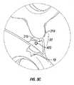
この鉗子10は、細長いシャフト部分12aおよび12bを含み、各々は、近位端14a、14bおよび遠位端16a、16bをそれぞれ有する。図面および以下の説明においては、用語「近位」は、伝統的であるように、使用者により近い鉗子10の端部をいい、その一方、用語「遠位」は、使用者からより遠い端部をいう。この鉗子10は、シャフト12aおよび12bの遠位端16aおよび16bにそれぞれ取り付けられる端部エフェクターアセンブリ100を含む。以下により詳細に説明されるように、この端部エフェクターアセンブリ100は、旋回ピン65の周りに旋回可能に連結され、そして組織を握るために互いに対して移動可能である1対の対向する顎部材110および120を含む。 The
好ましくは、各シャフト12aおよび12bは、それらの近位端14aおよび14bにそれぞれ配置されたハンドル15および17を含み、これらは各々、それを通って使用者の指を受容するための指穴15aおよび17aをそれぞれ規定する。認識され得るように、指穴15aおよび17aは、シャフト12aおよび12bの互いに対する移動を容易にし、これは、次に、上記顎部材110および120を、これら顎部材110および120が互いに対して間隔を置いた関係で配置される開放位置から、これら顎部材110および120がそれらの間に組織を握るために協働するクランプまたは閉鎖位置まで旋回する。 Preferably, each
図3Eで最も良く観察されるように、シャフト12bは、2つの構成要素、すなわち、12b1および12b2から構成され、これらは、シャフト12aの遠位端16aの周りで互いに嵌合して係合し、シャフト12bを形成する。これら2つの構成要素の半分体12b1および12b2は、複数の異なる溶接点において超音波により一緒に溶接され得るか、またはこれら2つの構成要素の半分体12b1および12b2は、任意のその他の公知の様式、スナップばめ、接着剤、ねじなどで機械的に係合され得ることが想定される。構成要素半分体12b1および12b2が一緒に溶接されてシャフト12bを形成した後、シャフト12aが旋回軸65の周りに固定され、そしてシャフト部分12b2内に規定される切り欠きまたはリリーフ21内に、シャフト12aがシャフト12bに対して移動可能であるように位置決めされる。より詳細には、使用者がこのシャフト12aをシャフト12bに対して移動し、これら顎部材110および120を閉鎖または開放するとき、シャフト12aの遠位部分は、部分12b2内に形成された切り欠き21内で移動する。これら2つのシャフト12aおよび12bをこの様式の形態とすることは、握ることを容易にし、そして鉗子10の全体のサイズを減少する。このことは、小さな腔における手術の間に特に有利である。 As best seen in FIG. 3E,
図3A〜3Bに最も良く示されるように、シャフトの1つ、例えば、12bは、鉗子10を電源20に接続するように設計されている近位シャフトコネクター77を含む。この近位シャフトコネクター77は、ケーブル70を、使用者が必要に応じて電気外科エネルギーを選択的に付与し得るように電気機械的に係合する。あるいは、このケーブル70は、シャフト12b(または12a)中に直接供給され得る。このケーブル70は、電源20とのインターフェースをするプラグ300に連結される。 As best shown in FIGS. 3A-3B, one of the shafts, eg, 12b, includes a proximal shaft connector 77 that is designed to connect the
以下により詳細に説明されるように、ケーブル70の遠位端は、ハンドスイッチ50に接続され、使用者が必要に応じて電気外科用エネルギーを選択的に印加し、顎部材110と120との間に握られた組織をシールすることを可能にする。より詳細には、ケーブル70の内部は、配線71a、71bおよび71cを収容し、これらは、ハンドスイッチ50の起動に際し、上記電気外科電源からの異なる電位を顎部材110および120に伝導する(図4を参照のこと)。認識され得るように、スイッチ50を鉗子10に位置決めすることは、使用者に、電気外科エネルギーの付与に対してより大きな視覚および触覚制御を与える。これらの局面は、ハンドスイッチ50およびそれと関連する電気的接続の論議に対して以下に説明される。 As will be described in more detail below, the distal end of
端部エフェクターアセンブリ100の2つの対向する顎部材110および120は、それらの間に組織を握るために開放位置から閉鎖位置までピン65の周りを旋回可能である。この旋回ピンは、顎部材120中のアパーチャ125、そして顎部材110を通って配置されたアパーチャ111を通って接続する。旋回ピン65は、代表的には、2つの構成要素半分体65aおよび65bからなり、これらは、組立ての間に、これら顎部材110および120が開放位置と閉鎖位置との間を自由に旋回可能であるようにシャフト12aおよび12bを嵌合して係合し、そして旋回可能に固定する。例えば、この旋回ピン65は、旋回がこの旋回ピン65の周りの回転のために2つのシャフト12aおよび12bを固定するために、組み立てに際し一緒にスナップばめするようにスプリングで負荷されるような形態であり得る。 The two opposing
これら顎部材110および120の組織を握る部分はほぼ対称であり、そして旋回ピン65の周りの容易な回転を可能にするために協働し、組織の握持およびシールを行う類似の構成要素特徴を含む。結果として、そしてその他であることが注記されなければ、顎部材110およびそれにともなう作動特徴は、本明細書中に詳細に最初に記載され、そして顎部材120に関する類似の構成要素特徴は、その後に簡単に要約される。さらに、顎部材110および120の多くの特徴は、本出願人が所有する米国特許出願第10/284,562号、同第10/116,824号、同第09/425,696号、同第09/178,027号、およびPCT出願番号第PCT/US01/11420号に詳細に記載され、これらの内容はすべて、本明細書中にそれらの全体が本明細書によって参考として援用される。 The tissue gripping portions of these
図5で最も良く観察されるように、顎部材110は、電気的に伝導性のシール面112と機械的に係合するような寸法である絶縁された外側ハウジング116を含む。この外側絶縁性ハウジング116は、顎部材110の全長に沿って延び、シールの間の交互のまたは漂遊の電流経路および/または組織への偶然の損傷を減少する。この電気的に伝導性の面112は、ハンドスイッチ50の起動に際し、第1の電位の電気外科エネルギーを組織に伝導する。絶縁された外側ハウジング116は、電気的に伝導性のシール面112を固定して係合するような寸法である。これは、スタンピングにより、オーバーモールディングにより、スタンプされた電気的に伝導性のシールプレートをオーバーモールドすることにより、そして/または金属射出成形シールプレートをオーバーモールドすることにより達成され得ることが想定される。このシール面112を外側ハウジング116に固定するその他の方法は、1つ以上の上記で識別された参考文献中に詳細に記載されている。上記顎部材110および120は、代表的には、伝導性材料から作製され、そして絶縁性被覆で粉末被覆され、シールする間の漂遊電流濃度を低減する。 As best seen in FIG. 5,
同様に、図3Eに示されるように、顎部材120は類似の要素を含み、これは:電気的に伝導性のシール面122と係合する外側ハウジング126、ハンドスイッチ50の起動に際し、組織に第2の電位の電気外科エネルギーを伝導する電気的に伝導性のシール面122を含む。 Similarly, as shown in FIG. 3E,
図5および図3Eで最も良く観察されるように、顎部材110および120は、それらの中の切断機構80の往復を可能にするような形態である、それらの間に配置されたナイフチャネル115を含む。ナイフチャネルの1つの例は、本出願人が所有する米国特許出願第10/284,562号に開示され、それらの全体の内容は、本明細書によって、本明細書中に参考として援用される。このナイフチャネル115はテーパー状であり得るか、または遠位方向の切断機構80の往復の間に組織の切断を容易にするか、または増大する特定のその他の形態であり得ることが想定される。さらに、このナイフチャネル115は、顎部材110および120が組織の周りで閉鎖されるまで、この切断機構80が組織を通って進行することを防ぐ1つ以上の安全特徴とともに形成され得る。 As best seen in FIGS. 5 and 3E, the
シャフト12bの配列は、シャフト12aとはわずかに異なる。より詳細には、シャフト12bは、ほぼ中空であり、ハンドスイッチ50(およびそれと関連する電気的構成要素)、起動機構40および切断機構80を収容するような寸法である、それを通って延びるチャンバー28を規定する。図4および図3Eで最も良く観察されるように、この起動機構40は、第1および第2のギアトラック42および86をそれぞれ有するラックおよびピニオンシステムを含み、そしてピニオン45が切断機構80を進行する。より詳細には、この起動機構40は、トリガーまたは指タブ43を含み、これは、指ギアラック42と作動可能に関連し、このトリガーまたは指タブ43の移動が、この第1のラック42を対応する方向に移動する。この起動機構40は、駆動ロッド89と作動可能に関連し、そして全体の切断機構80を進行する第2のギアラック86と機械的に協働する。駆動ロッド89は、切断ブレード85を機械的に支持するような形態であり、そして以下により詳細に説明されるように安全ロックアウト機構の一部として作用する遠位端81を含む。 The arrangement of the
第1のギアラック42と第2のギアラック86との間にそれぞれ配置されて、ピニオンギア45があり、これは、両方のギアラック42および86と機械的に歯車が噛み合い、そしてトリガー43の近位方向運動を駆動ロッド89の遠位転移に変換する。逆もまた真実である。より詳細には、使用者がトリガー43を、シャフト12b中の予め配置されたチャネル29内で近位方向に引くとき(図3E中の矢印「A」を参照のこと)、第1のラック42は近位方向に転移し、これは、次に、ピニオンギア45を反時計方向に回転する。このピニオンギア45の反時計方向の回転は、第2のラック86を押し、駆動ロッド89を遠位方向に転移し(図3E中の矢印「B」を参照のこと)、これは、切断機構80のブレード85を顎部材110と120との間に握られた組織を通って進行し、すなわち、この切断機構80、例えば、ナイフ、ブレード、ワイヤなどは、駆動ロッド89の遠位転移に際し、チャネル115を通って進行される。 Arranged between the
スプリング83がチャンバー28内で採用され、トリガー43の解放の際に、このスプリング83の力が第1のラック42をチャネル29内のその最遠位位置まで自動的に戻すように、その近位方向移動に際して第1のラック42を付勢し得る。このスプリング83は、第2のラック86を付勢するように作動可能に接続され得、同じ目的を達成する。 A
顎部材120の近位部分はまた、それを通って規定される、顎部材110および120の開放位置から閉鎖位置への移動に際し、末端コネクター150、またはいわゆる「POGO」ピンがその中に載ることを可能にする案内スロット124を含む。この末端コネクター150は、代表的には、顎部材110の窪み113内に着座される。さらに、上記近位端は、それを通って規定され、旋回ピン65を収容するアパーチャ125を含む。この末端コネクター150は、顎部材110および120の回転に際し、スロット124内で自由に移動する。この末端コネクター150は、顎部材110内のアパーチャ151内に着座され、そして顎部材120のスロット124内に載り、鉗子10の旋回運動の間に顎部材120に電気外科エネルギーを供給する「稼動」または「ブラシ」接触を提供することが想定される。 The proximal portion of the
顎部材110および120は、互いから、電気外科エネルギーが組織を通って効率的に移され得、組織シールを形成するように電気的に絶縁される。各顎部材、例えば、110は、それを通って配置され、電気外科エネルギーを電気的に伝導性のシール面112に伝達する特有に設計された電気外科ケーブル経路を含む。これら顎部材110および120は、これらケーブル配線を電気的に伝導性のシール面112および122の方に向ける1つ以上のケーブルガイドまたはクリンプ様電気コネクターを含み得ることが想定される。好ましくは、ケーブル配線は、上記ケーブル経路に沿って堅く保持され、顎部材110および120の旋回軸65の周りの旋回を可能にする。
作動において、使用者は、顎部材110と120との間に組織を握るために、単にこれら2つの対向するハンドル部材15および17を利用する。使用者は、次に、ハンドスイッチ50を起動し、各顎部材110および120に電気外科エネルギーを提供し、それらの間に保持された組織を通ってエネルギーを伝達し、組織シールを行う(図21および22を参照のこと)。一旦、シールされると、使用者は、起動機構40を起動し、切断ブレード85を組織を通って進行し、組織シールに沿って組織を切断し、組織半分体の間に分裂を生成する。 In operation, the user simply utilizes these two opposing
図3A〜3Dは、顎部材110および120を、旋回の間に、少なくとも1つの位置で互いに対して選択的にロックするためのラチェット30を示す。第1のラチェットインターフェース31aは、シャフト12bの近位端14b上で、それとほぼ垂直方向に、シャフト部材12aの近位端14aから、第2のラチェットインターフェース31bに向かって延び、その結果、各々のラチェット31aおよび31bの内側に面する面は、組織の周りの顎部材110および120の閉鎖に際して互いに接する。各々のラチェットインターフェース31aおよび31bは、各々のラチェットインターフェース31aおよび31bの内側に面する面から、これらラチェットインターフェース31aおよび31bが少なくとも1つの位置で相互ロックするように突出する複数の階段状フランジ(図示せず)を含み得ることが想定される。好ましくは、協働するラチェットインターフェース31aおよび31bと関連する各位置は、シャフト部材12aおよび12b中に、特定の、すなわち、一定のひずみエネルギーを保持し、これは、次いで、顎部材110および120に特定の閉鎖力を伝達する。 3A-3D show a
ラチェット30は、使用者が、これら顎部材間で所望される閉鎖力の量を容易かつ迅速に確認および制御することを可能にする目盛りまたはその他の視覚マーキングを含み得ることが想定される。シャフト12aおよび12bは、ラチェットで動かされるとき、顎部材110および120に上記に記載された作動範囲内で特定の閉鎖圧力を付与するために調整される特定のプラスチック材料から製造され得ることが想定される。認識され得るように、これは、製造プロセスを単純化し、そしてシールプロセスの間に顎部材110および120を過小加圧および過剰加圧することをなくする。 It is envisioned that
近位コネクター77は、使用者が、ラチェット位置を超えてハンドル15および17を強く握ることにより顎部材110および120を過剰加圧することを防ぐ、ストップまたは突出部19(図3B〜Dを参照のこと)を含み得る。認識され得るように、これは、ラチェットで動かされるとき、鉗子10が、シールすることを行うために対向する顎部材110と120との間でそれぞれ必要な閉鎖圧力(約3kg/cm2〜約16kg/cm2)を維持するように自動的に構成されるという事実に起因して、一貫し、かつ有効なシールを容易にする。顎部材を過剰加圧することは有効でない組織シールに至り得ることが知られている。Proximal connector 77 prevents stop or protrusion 19 (see FIGS. 3B-D) from preventing the user from
図3Eおよび図4は、スイッチ50に関する電気的詳細を示す。より特定して、そして上記で述べたように、ケーブル70は、シャフト12bを通って供給される3つの電気配線71a、71bおよび71cを含む。これらケーブル配線71a、71bおよび71cは、2つの絶縁層、3つすべての配線71a、71bおよび71cを取り囲む外側保護シース、および個々の各ケーブル配線71a、71bおよび71cをそれぞれ取り囲む第2の保護シースによって保護される。2つの電位は、各ケーブル配線71a、71bおよび71cを取り囲む絶縁性でシースすることのために互いから隔離される。電気外科ケーブル70は、シャフト12bの底に供給され、そして1つ以上の機械的インターフェースによってその中に堅く保持される(明瞭には図示されていない)。 3E and 4 show the electrical details for the
配線71cはケーブル70から直接延び、そして顎部材120に接続し、第2の電位をそれに伝導する。配線71aおよび71bはケーブル70から延び、そして回路板52に接続する。配線71a〜71bは、クリンプ様コネクター(明瞭には図示されていない)、または当該技術分野で共通して知られるその他の電気機械的接続、例えば、IDC接続、ハンダなどによって回路板52から延びる一連の対応する接点に固定される。これら配線71a〜71bは、異なる電位または制御信号を回路板52に伝達するような形態であり、これは、次に、顎部材110および120への電気エネルギーを調節、モニターおよび制御する。より詳細には、図4に見られるように、電気配線71aおよび71bは、回路板52に、スイッチ50が押し下げられるとき、トリガー配線72が回路板52から顎部材110に第1の電位を運ぶように電気的に接続される。上記で述べたように、第2の電位は、配線71cによって電源20から顎部材120に直接、上記で記載されたように、端部コネクター150を通って運ばれる。 Wiring 71c extends directly from
図3Aおよび図3Eに最も良く示されるように、スイッチ50は、(一旦組立てられると)ハウジング20の外側形状に実質的に一致する人間工学的な寸法のトグルプレート53を含む。このトグルプレート53は、シャフト12bの1つの側面に沿って回路板52と電気−機械的伝達に位置決めされ、スイッチ50の起動を容易にする。認識され得るように、スイッチキャップ53の位置は、使用者が片腕で顎部材110および120に容易かつ選択的にエネルギーを与えることを可能にする。スイッチキャップ53は、湿潤作動条件の間に回路板52への損傷を避けるように密封してシールされ得ることが想定される。さらに、このスイッチキャップ53を鉗子10の側面に位置決めすることにより、全体のシールするプロセスが大いに単純化され、そして使用者に人間工学的に有利であり、すなわち、閉鎖後、使用者の指が切断機構80の進行に対して自動的に釣合わされることが企図される。 As best shown in FIGS. 3A and 3E, the
トグルプレート53は、遠位方向に延び、そしてシャフト12b内に配置された対応する対の機械的インターフェース54aおよび54bと嵌合する1対のプロング53aおよび53bを含む。プロング53aおよび53bは、好ましくは、組立ての間にシャフト12bにスナップばめする。トグルプレート53はまた、スイッチボタン56と嵌合するスイッチインターフェース55を含み、これは、次に、回路板52に接続する。トグルプレート53が押し下げられるとき、スイッチボタン56は回路板52に対して押され、それによってハンドスイッチ50を起動する。
いくつかの異なるタイプのハンドスイッチ50が想定され、例えば、スイッチ50は、通常のプッシュボタンスタイルスイッチであるが、使用者が、種々の異なる配向、すなわち、起動を単純にする複数配向起動で鉗子10を選択的に起動することを可能にするよりトグルスイッチのような形態であり得る。1つの特定タイプのハンドスイッチは、本出願人が所有する同時係属中の米国特許出願第10/460,926号に開示され、その内容は、本明細書によって本明細書中に参考として援用される。 Several different types of hand switches 50 are envisioned, for example, the
図6Aは、本開示によるロックアウト機構200を示す。このロックアウト機構200は、スイッチ50の起動を防ぐような形態である。このロックアウト機構200は、スイッチ50が押し下げられ、スイッチボタン56を起動することを防ぐ。このロックアウト機構200は、ロックアウトバー214から横方向に延びる起動ノブ212を有するロックアウトスイッチ210を含む。起動ノブ212は、ロックアウトバー214に固定される。あるいは、このロックアウトバー214および起動ノブ212は、一体に形成され得る。起動ノブ212は、組立てられるときシャフト12bの側面から突出するような寸法であり、そして握ることを容易にする形態である種々の突出部を含み得る。ロックアウトスイッチ210は、絶縁性材料(例えば、プラスチック、セラミック)から形成され得るか、または被覆され得、ロックアウトスイッチ210を、任意の電流が器具を通って流れることから絶縁する。 FIG. 6A illustrates a
このロックアウトスイッチ210は、シャフト12bの案内チャネル220内に、このロックアウトスイッチ210がその中で方向「C」に選択的に移動可能であるようにスライド可能に配置される。このロックアウトスイッチ210は、ハンドスイッチ50に向かって任意の方向に面して配置され得、そしてシャフト12b内でスライドするような形態である。起動ノブ212がシャフト12bの外側に沿って移動されるとき、ロックアウトバー214は、その中で対応して移動する。開放形態では、ロックアウトスイッチ210は、方向「C」とは反対にスイッチ50から離れて移動される。これは、トグルプレート53が、押し下げられるとき、スイッチボタン56を回路板52との接触に押し、そしてそれによって、電気外科エネルギーの付与をトグル操作する。図6Bに示されるようなロックする形態では、ロックアウトスイッチ210は、ロックアウトバー214がトグルプレート53と回路板52との間に少なくとも部分的に配置されるように方向「C」にスライドする。ロックする形態では、トグルプレート53が押し下げられるとき、トグルプレート53は、ロックアウトバー214に対して押し、そしてスイッチボタン56が起動することが防がれる。このロックアウトバー214は、トグルプレート53と摩擦接触にあるか、またはこのトグルプレート53の移動がなお制限されるようにそれから所定の距離離れているかのいずれかであり得る。 The
このロックアウト機構200はさらに、1つ以上の触覚フィードバック要素、すなわち、案内チャネル220内に配置された移動止め224、およびこの移動止め224とインターフェースするような形態である溝222を含み得る。この溝222は、移動止め224と同じ長軸方向軸上のロックアウトバー214に、ロックアウトスイッチ210が方向「C」に移動されるとき、溝222が移動止め224とインターフェースし、使用者に触覚フィードバックを提供するように配置される。この溝222および移動止め224はまた、ロックアウトスイッチ210とシャフト12bとの間で摩擦接触を提供し、そしてロックアウトスイッチ210がロックする形態からスライドすることを防ぐような寸法である。 The
図7A〜Bは、異なる実施形態のロックアウト機構200を示す。ロックアウトスイッチ210は、種々の形状およびサイズで形成され得る。図7Aに示されるように、ロックアウトスイッチ210は、細長い形状を有するロックアウトバー214を含み得る。図7Bは、トグルプレート53の下の位置にスライドするいわゆるU形状ロック216を有するロックアウトスイッチ210を示す。トグルプレート53は、その中に配置される案内チャネルまたは溝(明瞭には図示されない)を含み得、これは、ロックアウトスイッチ210がロックする形態にスライドされるとき、ロックアウトバー214および/またはU形状ロック216とのインターフェースをするような形態である。 7A-B illustrate a different
図6A〜Bおよび7A〜Bに示される機械的ロックアウト機構200に加え、種々の電気的および電気機械的ロックアウト機構が企図される。図8は、電気的ロックアウト機構400を示す。鉗子10のプラグ300は、電源20中に挿し込まれ、そして対応する配線71a、71bおよび71cを接続する複数のプロング302、304および306を含む。プロング306は、シールプレート122に配線71cを経由する電源20への直接接続を提供する。プロング302および304は、配線71aおよび71bを経由して回路板52に接続される。回路板52は、配線72を経由してシールプレート112に連結される。作動の間に、スイッチ50は、回路板52に接触するスイッチボタン56を起動する。この回路板は、シールプレート112および電源20に連続して接続される起動スイッチ52aを含む。スイッチ52aは、スイッチボタン56を経由してトグル動作する。起動スイッチ52aが閉鎖され、そして組織がシールプレート112と122との間に握られるとき、回路は完成し、そして電気外科エネルギーが組織に伝達される。回路板52はまた、これもまた起動スイッチ52aと連続している安全スイッチ52bを含む。これらスイッチのいずれかが開いている限り、この回路は完成せず、そして組織に電気外科エネルギーは供給されない。 In addition to the
安全スイッチ52bは、鉗子10に沿っていずれかに配置されたロックアウトプッシュボタンを経由してトグル操作され得る。このロックアウトプッシュボタンは、手動または自動的いずれかで起動され得る。特に、このロックアウトプッシュボタンの自動起動は、鉗子10の閉鎖により達成され得る。図3Cに示されるように、ロックアウトプッシュボタン400は、第2のラチェットインターフェース31bの内側に面する面上に、鉗子10の閉鎖の間に、第1および第2のインターフェース31aおよび31bが、各々、互いに接するとき、ロックアウトプッシュボタン400が起動され(すなわち、概略的に図示された安全スイッチ52bが閉鎖され)、電気外科エネルギーの選択的付与を可能にするように配置され得る。 The
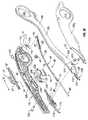
前述から、そして種々の図の描写を参照して、当業者は、特定の改変がまた本開示の範囲から逸脱することなく本開示になされ得ることを認識する。例えば、そして上記で述べたように、本明細書中に開示された任意のロックアウト機構が、図9に開示される内視鏡鉗子500のような内視鏡鉗子中で採用される得ることが企図される。 From the foregoing and with reference to the various figure depictions, those skilled in the art will recognize that certain modifications may also be made to the present disclosure without departing from the scope of the present disclosure. For example, and as described above, any lockout mechanism disclosed herein can be employed in an endoscopic forceps, such as
図9は、その遠位端で端部エフェクターアセンブリ502を支持するような形態である鉗子500を示す。より詳細には、鉗子500は、一般に、ハウジング504、ハンドルアセンブリ506、回転アセンブリ508、および組織を握り、シールし、そして要求されれば分割するためにこの端部エフェクターアセンブリ502と互いに協働するトリガーアセンブリ510を含む。 FIG. 9 shows a
この鉗子500はまた、端部エフェクターアセンブリ502を機械的に係合する遠位端514、および回転アセンブリ508の近位方向のハウジング504を機械的に係合する近位端516を有するシャフト512を含む。図面において、そして以下の説明において、用語「近位」は、使用者により近い鉗子500の端部をいい、その一方、用語「遠位」は、使用者からより遠いこの鉗子の端部をいう。 The
ハンドルアセンブリ506は、固定されたハンドル520および移動可能なハンドル522を含む。ハンドル522は、固定されたハンドル520に対して移動し、端部エフェクターアセンブリ502を起動し、そして使用者が組織を握ることそして操作することを可能にする。
端部エフェクターアセンブリ502は、一対の対向する顎部材524および526を含み、各々は、それらの間に保持された組織を通って電気外科エネルギーを伝導するためのそれらに各々取り付けられた電気的に伝導性のシールプレート(明瞭には示されていない)を有する。より詳細には、これら顎部材524および526は、ハンドル522の移動に応答して、開放位置から閉鎖位置まで移動する。開放位置では、シールプレートは、互いに対して間隔を置いた関係で配置される。クランプする、または閉鎖位置では、これらシールプレートは協働して組織を握り、そして一旦使用者が、ハウジング504上に配置されているハンドスイッチ50を起動すると、それに電気外科エネルギーを付与する。
これら顎部材524および526は、ハウジング504内に囲われた駆動アセンブリ(示されず)を用いて起動される。この駆動アセンブリは、移動可能なハンドル522と協働し、開放位置から、クランプする、または閉鎖位置までの顎部材524および526の移動を与える。ハンドルアセンブリの例は、本出願人が所有する「血管シーラーおよび分割器およびそれらを製造する方法」と題する米国出願番号第10/389,894号、および本出願人が所有する「小トロカールおよびカニューレとの使用のための血管シーラーおよび分割器」と題する米国出願番号第10/460,926号に示され、そして記載されており、これら両方は、それらの全体が本明細書中に本明細書によって援用される。 These
さらに、この特定の開示のハンドルアセンブリ506は、4つのバーの機械的リンケージを含み得、これは、顎部材524および526の間に組織をシールするとき特有の機械的利点を提供する。例えば、一旦、シールする部位について所望の位置が決定され、そして顎部材524および526が適正に位置決めされると、ハンドル522が完全に押され、上記電気的に伝導性のシールプレートを組織に対して閉鎖位置にロックする。ハンドルアセンブリ506の移動可能なハンドル522は、シャフト512内に収容される駆動ロッド(明瞭には示されない)に最終的に接続され、これは、一緒に機械的に協働して、顎部材524および526が互いに対して間隔を置いて配置される開放位置から、顎部材524および526がそれらの間に組織を握るために協働する閉鎖位置までの顎部材524および526の移動を与える。 Additionally, the
1つの特定の開放鉗子に関するさらなる詳細は、本出願人が所有する「小トロカールおよびカニューレとの使用のための血管シーラーおよび分割器」と題する、2003年6月13日に出願された米国出願番号第10/460、926号に開示され、その全体の内容は、本明細書中に参考として援用される。 Further details regarding one particular open forceps can be found in U.S. Application No. filed Jun. 13, 2003, entitled “Vessel Sealer and Divider for Use with Small Trocars and Cannulas” owned by the Applicant. No. 10 / 460,926, the entire contents of which are incorporated herein by reference.
前述から、そして種々の図の描写を参照して、当業者は、特定の改変がまた本開示の範囲から逸脱することになく本開示になされ得ることを認識する。例えば、上記の電気的接続は、好ましくは、1つのシャフト12b内に取り込まれ、そして鉗子10は右手使用のために意図されるが、上記電気的接続が、特定の目的に依存して他方のシャフト12a内に取り込まれ得ることが企図され、そして/または左手使用者による操作を容易にする。あるいは、この鉗子10は、鉗子10の任意の作動特徴を損傷または制限することなく、左手使用者のために上下転倒した配向で作動され得る
鉗子10(および/または鉗子10と組合せて用いられる電源)が、顎部材110および120の間に握られた特有サイズの組織を有効にシールするために適切な量の電気外科エネルギーを自動的に選択するセンサーまたはフィードバック機構(明瞭には示されず)を含み得る。このセンサーまたはフィードバック機構はまた、シールする間に組織を横切るインピーダンスを測定し得、そして顎部材110と120との間で有効なシールが生成されたことの指標(視覚および/または音響)を提供し得る。本出願人が所有する米国特許出願第10/427,832号は、この目的のために利用され得るいくつかの異なるタイプの感知フィードバック機構およびアルゴリズムを開示している。この出願の内容は、本明細書によって、本明細書中に参考として援用される。From the foregoing and with reference to the various figure depictions, those skilled in the art will recognize that certain modifications may also be made to the present disclosure without departing from the scope of the present disclosure. For example, the electrical connection described above is preferably captured within one
安全スイッチまたは回路(図示されず)が、スイッチ50が、顎部材110と120とが閉鎖されなければ、そして/または顎部材110と120とがそれらの間に保持された組織400有さなければ発射し得ないように採用され得ることが想定される。後者の例では、センサー(明瞭に示されず)が、組織がそれらの間に保持されているか否かを決定するために採用され得る。さらに、手術前、手術と同時(すなわち、手術の間)および/または手術後状態を決定するその他のセンサー機構が採用され得る。このセンサー機構はまた、1つ以上の手術前、手術と同時または手術後状態に基づき電気外科エネルギーを調節するために電源に連結される閉鎖されたループフィードバックシステムとともに利用され得る。種々のセンサー機構およびフィードバックシステムが、本出願人が所有する同時係属中の米国特許出願第10/427,832号に記載され、この全体の内容は、本明細書によって本明細書中に参考として援用される。 A safety switch or circuit (not shown) may be required if
本明細書中に開示される機械的および電気的ロックアウト機構が、余分のロックアウトシステムを提供して単一の器具に含められ得ることもまた想定される。 It is also envisioned that the mechanical and electrical lockout mechanisms disclosed herein can be included in a single instrument providing an extra lockout system.
本開示のいくつかの実施形態が図面中に示され、そして/または本明細書中で論議されているが、本開示がそれに制限されることは意図されない。なぜなら、本開示は、当該技術分野が可能にし、そして本明細書が同様に読まれるように広い範囲であることが意図されるからである。従って、上記の説明は、制限的であると解釈されるべきではなく、特定の実施形態の単なる例示として解釈されるべきである。当業者は、本明細書に添付された請求項の範囲および思想内でその他の改変を考案し得る。 Although some embodiments of the present disclosure are shown in the drawings and / or discussed herein, it is not intended that the present disclosure be limited thereto. This is because the present disclosure is intended to be broad in scope so that the art will allow and the specification will be read as well. Therefore, the above description should not be construed as limiting, but merely as exemplifications of particular embodiments. Those skilled in the art may devise other modifications within the scope and spirit of the claims appended hereto.
10 鉗子
12 シャフト
20 電源
30 ラチェット
50 ハンドスイッチ
100 エフェクターアセンブリ
200 ロックアウト機構
210 ロックアウトスイッチDESCRIPTION OF
Claims (1)
Translated fromJapaneseApplications Claiming Priority (2)
| Application Number | Priority Date | Filing Date | Title |
|---|---|---|---|
| US11/499,590 | 2006-08-04 | ||
| US11/499,590US20080033428A1 (en) | 2006-08-04 | 2006-08-04 | System and method for disabling handswitching on an electrosurgical instrument |
Related Parent Applications (1)
| Application Number | Title | Priority Date | Filing Date |
|---|---|---|---|
| JP2007203665ADivisionJP2008036437A (en) | 2006-08-04 | 2007-08-03 | Hand-held electrosurgical instrument having locking hand switch |
Publications (1)
| Publication Number | Publication Date |
|---|---|
| JP2012192242Atrue JP2012192242A (en) | 2012-10-11 |
Family
ID=38728914
Family Applications (2)
| Application Number | Title | Priority Date | Filing Date |
|---|---|---|---|
| JP2007203665APendingJP2008036437A (en) | 2006-08-04 | 2007-08-03 | Hand-held electrosurgical instrument having locking hand switch |
| JP2012155479APendingJP2012192242A (en) | 2006-08-04 | 2012-07-11 | Handheld electrosurgical instrument having disable handswitch |
Family Applications Before (1)
| Application Number | Title | Priority Date | Filing Date |
|---|---|---|---|
| JP2007203665APendingJP2008036437A (en) | 2006-08-04 | 2007-08-03 | Hand-held electrosurgical instrument having locking hand switch |
Country Status (7)
| Country | Link |
|---|---|
| US (1) | US20080033428A1 (en) |
| EP (2) | EP1889583B1 (en) |
| JP (2) | JP2008036437A (en) |
| AU (1) | AU2007203637B2 (en) |
| CA (1) | CA2595817A1 (en) |
| DE (1) | DE602007013842D1 (en) |
| ES (1) | ES2364285T3 (en) |
Families Citing this family (177)
| Publication number | Priority date | Publication date | Assignee | Title |
|---|---|---|---|---|
| US6267761B1 (en)* | 1997-09-09 | 2001-07-31 | Sherwood Services Ag | Apparatus and method for sealing and cutting tissue |
| US6726686B2 (en) | 1997-11-12 | 2004-04-27 | Sherwood Services Ag | Bipolar electrosurgical instrument for sealing vessels |
| US7435249B2 (en)* | 1997-11-12 | 2008-10-14 | Covidien Ag | Electrosurgical instruments which reduces collateral damage to adjacent tissue |
| US6228083B1 (en)* | 1997-11-14 | 2001-05-08 | Sherwood Services Ag | Laparoscopic bipolar electrosurgical instrument |
| US7582087B2 (en)* | 1998-10-23 | 2009-09-01 | Covidien Ag | Vessel sealing instrument |
| US20040249374A1 (en) | 1998-10-23 | 2004-12-09 | Tetzlaff Philip M. | Vessel sealing instrument |
| US7364577B2 (en) | 2002-02-11 | 2008-04-29 | Sherwood Services Ag | Vessel sealing system |
| US7267677B2 (en) | 1998-10-23 | 2007-09-11 | Sherwood Services Ag | Vessel sealing instrument |
| US7118570B2 (en) | 2001-04-06 | 2006-10-10 | Sherwood Services Ag | Vessel sealing forceps with disposable electrodes |
| US7887535B2 (en)* | 1999-10-18 | 2011-02-15 | Covidien Ag | Vessel sealing wave jaw |
| US20030109875A1 (en) | 1999-10-22 | 2003-06-12 | Tetzlaff Philip M. | Open vessel sealing forceps with disposable electrodes |
| US20030229344A1 (en)* | 2002-01-22 | 2003-12-11 | Dycus Sean T. | Vessel sealer and divider and method of manufacturing same |
| ES2262639T3 (en) | 2001-04-06 | 2006-12-01 | Sherwood Services Ag | SHUTTER AND DIVIDER OF GLASSES WITH BUMPER MEMBERS N OCONDUCTIVES. |
| EP1527747B1 (en) | 2001-04-06 | 2015-09-30 | Covidien AG | Electrosurgical instrument which reduces collateral damage to adjacent tissue |
| US7101371B2 (en) | 2001-04-06 | 2006-09-05 | Dycus Sean T | Vessel sealer and divider |
| US10849681B2 (en) | 2001-04-06 | 2020-12-01 | Covidien Ag | Vessel sealer and divider |
| AU2001249937B2 (en)* | 2001-04-06 | 2006-02-09 | Covidien Ag | Vessel sealing instrument |
| AU2002250551B2 (en)* | 2001-04-06 | 2006-02-02 | Covidien Ag | Molded insulating hinge for bipolar instruments |
| US20040115296A1 (en)* | 2002-04-05 | 2004-06-17 | Duffin Terry M. | Retractable overmolded insert retention apparatus |
| EP1683496B1 (en)* | 2002-06-06 | 2008-12-10 | Covidien AG | Laparoscopic bipolar electrosurgical instrument |
| US7270664B2 (en)* | 2002-10-04 | 2007-09-18 | Sherwood Services Ag | Vessel sealing instrument with electrical cutting mechanism |
| US7931649B2 (en) | 2002-10-04 | 2011-04-26 | Tyco Healthcare Group Lp | Vessel sealing instrument with electrical cutting mechanism |
| US7276068B2 (en) | 2002-10-04 | 2007-10-02 | Sherwood Services Ag | Vessel sealing instrument with electrical cutting mechanism |
| US7799026B2 (en) | 2002-11-14 | 2010-09-21 | Covidien Ag | Compressible jaw configuration with bipolar RF output electrodes for soft tissue fusion |
| US7033354B2 (en)* | 2002-12-10 | 2006-04-25 | Sherwood Services Ag | Electrosurgical electrode having a non-conductive porous ceramic coating |
| US20060064086A1 (en)* | 2003-03-13 | 2006-03-23 | Darren Odom | Bipolar forceps with multiple electrode array end effector assembly |
| EP1601298B1 (en)* | 2003-03-13 | 2016-09-07 | Covidien AG | Bipolar concentric electrode assembly for soft tissue fusion |
| CA2523675C (en) | 2003-05-01 | 2016-04-26 | Sherwood Services Ag | Electrosurgical instrument which reduces thermal damage to adjacent tissue |
| US8128624B2 (en)* | 2003-05-01 | 2012-03-06 | Covidien Ag | Electrosurgical instrument that directs energy delivery and protects adjacent tissue |
| US7160299B2 (en) | 2003-05-01 | 2007-01-09 | Sherwood Services Ag | Method of fusing biomaterials with radiofrequency energy |
| JP5137230B2 (en) | 2003-05-15 | 2013-02-06 | コヴィディエン・アクチェンゲゼルシャフト | Tissue sealer with non-conductive variable stop member and method for sealing tissue |
| US7597693B2 (en)* | 2003-06-13 | 2009-10-06 | Covidien Ag | Vessel sealer and divider for use with small trocars and cannulas |
| US7150749B2 (en) | 2003-06-13 | 2006-12-19 | Sherwood Services Ag | Vessel sealer and divider having elongated knife stroke and safety cutting mechanism |
| US7857812B2 (en) | 2003-06-13 | 2010-12-28 | Covidien Ag | Vessel sealer and divider having elongated knife stroke and safety for cutting mechanism |
| US7156846B2 (en) | 2003-06-13 | 2007-01-02 | Sherwood Services Ag | Vessel sealer and divider for use with small trocars and cannulas |
| USD956973S1 (en) | 2003-06-13 | 2022-07-05 | Covidien Ag | Movable handle for endoscopic vessel sealer and divider |
| US9848938B2 (en) | 2003-11-13 | 2017-12-26 | Covidien Ag | Compressible jaw configuration with bipolar RF output electrodes for soft tissue fusion |
| US7367976B2 (en) | 2003-11-17 | 2008-05-06 | Sherwood Services Ag | Bipolar forceps having monopolar extension |
| US7232440B2 (en)* | 2003-11-17 | 2007-06-19 | Sherwood Services Ag | Bipolar forceps having monopolar extension |
| US7811283B2 (en)* | 2003-11-19 | 2010-10-12 | Covidien Ag | Open vessel sealing instrument with hourglass cutting mechanism and over-ratchet safety |
| US7131970B2 (en) | 2003-11-19 | 2006-11-07 | Sherwood Services Ag | Open vessel sealing instrument with cutting mechanism |
| US7500975B2 (en) | 2003-11-19 | 2009-03-10 | Covidien Ag | Spring loaded reciprocating tissue cutting mechanism in a forceps-style electrosurgical instrument |
| US7442193B2 (en) | 2003-11-20 | 2008-10-28 | Covidien Ag | Electrically conductive/insulative over-shoe for tissue fusion |
| US7780662B2 (en) | 2004-03-02 | 2010-08-24 | Covidien Ag | Vessel sealing system using capacitive RF dielectric heating |
| US7195631B2 (en)* | 2004-09-09 | 2007-03-27 | Sherwood Services Ag | Forceps with spring loaded end effector assembly |
| US7540872B2 (en) | 2004-09-21 | 2009-06-02 | Covidien Ag | Articulating bipolar electrosurgical instrument |
| US20060190035A1 (en)* | 2004-10-08 | 2006-08-24 | Sherwood Services Ag | Latching mechanism for forceps |
| US20060079933A1 (en)* | 2004-10-08 | 2006-04-13 | Dylan Hushka | Latching mechanism for forceps |
| US7955332B2 (en) | 2004-10-08 | 2011-06-07 | Covidien Ag | Mechanism for dividing tissue in a hemostat-style instrument |
| US7686827B2 (en) | 2004-10-21 | 2010-03-30 | Covidien Ag | Magnetic closure mechanism for hemostat |
| US7686804B2 (en) | 2005-01-14 | 2010-03-30 | Covidien Ag | Vessel sealer and divider with rotating sealer and cutter |
| US7909823B2 (en) | 2005-01-14 | 2011-03-22 | Covidien Ag | Open vessel sealing instrument |
| US7491202B2 (en) | 2005-03-31 | 2009-02-17 | Covidien Ag | Electrosurgical forceps with slow closure sealing plates and method of sealing tissue |
| US7837685B2 (en)* | 2005-07-13 | 2010-11-23 | Covidien Ag | Switch mechanisms for safe activation of energy on an electrosurgical instrument |
| US7628791B2 (en)* | 2005-08-19 | 2009-12-08 | Covidien Ag | Single action tissue sealer |
| US7922953B2 (en) | 2005-09-30 | 2011-04-12 | Covidien Ag | Method for manufacturing an end effector assembly |
| US7879035B2 (en) | 2005-09-30 | 2011-02-01 | Covidien Ag | Insulating boot for electrosurgical forceps |
| US7789878B2 (en) | 2005-09-30 | 2010-09-07 | Covidien Ag | In-line vessel sealer and divider |
| US7722607B2 (en) | 2005-09-30 | 2010-05-25 | Covidien Ag | In-line vessel sealer and divider |
| ES2381560T3 (en) | 2005-09-30 | 2012-05-29 | Covidien Ag | Insulating sleeve for electrosurgical forceps |
| CA2561034C (en) | 2005-09-30 | 2014-12-09 | Sherwood Services Ag | Flexible endoscopic catheter with an end effector for coagulating and transfecting tissue |
| US7594916B2 (en)* | 2005-11-22 | 2009-09-29 | Covidien Ag | Electrosurgical forceps with energy based tissue division |
| US20070118115A1 (en)* | 2005-11-22 | 2007-05-24 | Sherwood Services Ag | Bipolar electrosurgical sealing instrument having an improved tissue gripping device |
| US7766910B2 (en)* | 2006-01-24 | 2010-08-03 | Tyco Healthcare Group Lp | Vessel sealer and divider for large tissue structures |
| US8734443B2 (en) | 2006-01-24 | 2014-05-27 | Covidien Lp | Vessel sealer and divider for large tissue structures |
| US8241282B2 (en) | 2006-01-24 | 2012-08-14 | Tyco Healthcare Group Lp | Vessel sealing cutting assemblies |
| US8882766B2 (en)* | 2006-01-24 | 2014-11-11 | Covidien Ag | Method and system for controlling delivery of energy to divide tissue |
| US8298232B2 (en) | 2006-01-24 | 2012-10-30 | Tyco Healthcare Group Lp | Endoscopic vessel sealer and divider for large tissue structures |
| US7641653B2 (en)* | 2006-05-04 | 2010-01-05 | Covidien Ag | Open vessel sealing forceps disposable handswitch |
| US20070260238A1 (en)* | 2006-05-05 | 2007-11-08 | Sherwood Services Ag | Combined energy level button |
| US7846158B2 (en) | 2006-05-05 | 2010-12-07 | Covidien Ag | Apparatus and method for electrode thermosurgery |
| US20070265616A1 (en)* | 2006-05-10 | 2007-11-15 | Sherwood Services Ag | Vessel sealing instrument with optimized power density |
| US7776037B2 (en) | 2006-07-07 | 2010-08-17 | Covidien Ag | System and method for controlling electrode gap during tissue sealing |
| US20080015575A1 (en)* | 2006-07-14 | 2008-01-17 | Sherwood Services Ag | Vessel sealing instrument with pre-heated electrodes |
| US7744615B2 (en)* | 2006-07-18 | 2010-06-29 | Covidien Ag | Apparatus and method for transecting tissue on a bipolar vessel sealing instrument |
| US7731717B2 (en)* | 2006-08-08 | 2010-06-08 | Covidien Ag | System and method for controlling RF output during tissue sealing |
| US8597297B2 (en) | 2006-08-29 | 2013-12-03 | Covidien Ag | Vessel sealing instrument with multiple electrode configurations |
| US8070746B2 (en) | 2006-10-03 | 2011-12-06 | Tyco Healthcare Group Lp | Radiofrequency fusion of cardiac tissue |
| US7951149B2 (en)* | 2006-10-17 | 2011-05-31 | Tyco Healthcare Group Lp | Ablative material for use with tissue treatment device |
| US7785060B2 (en)* | 2006-10-27 | 2010-08-31 | Applied Materials, Inc. | Multi-directional mechanical scanning in an ion implanter |
| USD649249S1 (en) | 2007-02-15 | 2011-11-22 | Tyco Healthcare Group Lp | End effectors of an elongated dissecting and dividing instrument |
| US8267935B2 (en)* | 2007-04-04 | 2012-09-18 | Tyco Healthcare Group Lp | Electrosurgical instrument reducing current densities at an insulator conductor junction |
| US7877852B2 (en) | 2007-09-20 | 2011-02-01 | Tyco Healthcare Group Lp | Method of manufacturing an end effector assembly for sealing tissue |
| US7877853B2 (en) | 2007-09-20 | 2011-02-01 | Tyco Healthcare Group Lp | Method of manufacturing end effector assembly for sealing tissue |
| US8235992B2 (en) | 2007-09-28 | 2012-08-07 | Tyco Healthcare Group Lp | Insulating boot with mechanical reinforcement for electrosurgical forceps |
| US8235993B2 (en) | 2007-09-28 | 2012-08-07 | Tyco Healthcare Group Lp | Insulating boot for electrosurgical forceps with exohinged structure |
| US8267936B2 (en)* | 2007-09-28 | 2012-09-18 | Tyco Healthcare Group Lp | Insulating mechanically-interfaced adhesive for electrosurgical forceps |
| US8236025B2 (en) | 2007-09-28 | 2012-08-07 | Tyco Healthcare Group Lp | Silicone insulated electrosurgical forceps |
| AU2008221509B2 (en) | 2007-09-28 | 2013-10-10 | Covidien Lp | Dual durometer insulating boot for electrosurgical forceps |
| US8251996B2 (en) | 2007-09-28 | 2012-08-28 | Tyco Healthcare Group Lp | Insulating sheath for electrosurgical forceps |
| US8221416B2 (en) | 2007-09-28 | 2012-07-17 | Tyco Healthcare Group Lp | Insulating boot for electrosurgical forceps with thermoplastic clevis |
| US9023043B2 (en) | 2007-09-28 | 2015-05-05 | Covidien Lp | Insulating mechanically-interfaced boot and jaws for electrosurgical forceps |
| US8764748B2 (en) | 2008-02-06 | 2014-07-01 | Covidien Lp | End effector assembly for electrosurgical device and method for making the same |
| US8623276B2 (en) | 2008-02-15 | 2014-01-07 | Covidien Lp | Method and system for sterilizing an electrosurgical instrument |
| US8357158B2 (en) | 2008-04-22 | 2013-01-22 | Covidien Lp | Jaw closure detection system |
| US8469956B2 (en) | 2008-07-21 | 2013-06-25 | Covidien Lp | Variable resistor jaw |
| US8968355B2 (en) | 2008-08-04 | 2015-03-03 | Covidien Lp | Articulating surgical device |
| US8801752B2 (en)* | 2008-08-04 | 2014-08-12 | Covidien Lp | Articulating surgical device |
| US8257387B2 (en) | 2008-08-15 | 2012-09-04 | Tyco Healthcare Group Lp | Method of transferring pressure in an articulating surgical instrument |
| US8162973B2 (en) | 2008-08-15 | 2012-04-24 | Tyco Healthcare Group Lp | Method of transferring pressure in an articulating surgical instrument |
| US9603652B2 (en) | 2008-08-21 | 2017-03-28 | Covidien Lp | Electrosurgical instrument including a sensor |
| US8795274B2 (en) | 2008-08-28 | 2014-08-05 | Covidien Lp | Tissue fusion jaw angle improvement |
| US8317787B2 (en) | 2008-08-28 | 2012-11-27 | Covidien Lp | Tissue fusion jaw angle improvement |
| US8784417B2 (en) | 2008-08-28 | 2014-07-22 | Covidien Lp | Tissue fusion jaw angle improvement |
| US8303582B2 (en) | 2008-09-15 | 2012-11-06 | Tyco Healthcare Group Lp | Electrosurgical instrument having a coated electrode utilizing an atomic layer deposition technique |
| US8968314B2 (en) | 2008-09-25 | 2015-03-03 | Covidien Lp | Apparatus, system and method for performing an electrosurgical procedure |
| US9375254B2 (en) | 2008-09-25 | 2016-06-28 | Covidien Lp | Seal and separate algorithm |
| US8535312B2 (en) | 2008-09-25 | 2013-09-17 | Covidien Lp | Apparatus, system and method for performing an electrosurgical procedure |
| US8142473B2 (en) | 2008-10-03 | 2012-03-27 | Tyco Healthcare Group Lp | Method of transferring rotational motion in an articulating surgical instrument |
| US8469957B2 (en) | 2008-10-07 | 2013-06-25 | Covidien Lp | Apparatus, system, and method for performing an electrosurgical procedure |
| US8636761B2 (en) | 2008-10-09 | 2014-01-28 | Covidien Lp | Apparatus, system, and method for performing an endoscopic electrosurgical procedure |
| US8016827B2 (en) | 2008-10-09 | 2011-09-13 | Tyco Healthcare Group Lp | Apparatus, system, and method for performing an electrosurgical procedure |
| US8486107B2 (en) | 2008-10-20 | 2013-07-16 | Covidien Lp | Method of sealing tissue using radiofrequency energy |
| US8197479B2 (en) | 2008-12-10 | 2012-06-12 | Tyco Healthcare Group Lp | Vessel sealer and divider |
| US8114122B2 (en) | 2009-01-13 | 2012-02-14 | Tyco Healthcare Group Lp | Apparatus, system, and method for performing an electrosurgical procedure |
| US8282634B2 (en)* | 2009-01-14 | 2012-10-09 | Tyco Healthcare Group Lp | Apparatus, system, and method for performing an electrosurgical procedure |
| US20100249769A1 (en)* | 2009-03-24 | 2010-09-30 | Tyco Healthcare Group Lp | Apparatus for Tissue Sealing |
| US8444642B2 (en)* | 2009-04-03 | 2013-05-21 | Device Evolutions, Llc | Laparoscopic nephrectomy device |
| US8187273B2 (en) | 2009-05-07 | 2012-05-29 | Tyco Healthcare Group Lp | Apparatus, system, and method for performing an electrosurgical procedure |
| US8246618B2 (en) | 2009-07-08 | 2012-08-21 | Tyco Healthcare Group Lp | Electrosurgical jaws with offset knife |
| US8430876B2 (en) | 2009-08-27 | 2013-04-30 | Tyco Healthcare Group Lp | Vessel sealer and divider with knife lockout |
| US8133254B2 (en) | 2009-09-18 | 2012-03-13 | Tyco Healthcare Group Lp | In vivo attachable and detachable end effector assembly and laparoscopic surgical instrument and methods therefor |
| US8112871B2 (en) | 2009-09-28 | 2012-02-14 | Tyco Healthcare Group Lp | Method for manufacturing electrosurgical seal plates |
| US9024237B2 (en)* | 2009-09-29 | 2015-05-05 | Covidien Lp | Material fusing apparatus, system and method of use |
| US8808288B2 (en) | 2010-03-08 | 2014-08-19 | Covidien Lp | Surgical forceps including belt blade reverser mechanism |
| US9655672B2 (en)* | 2010-10-04 | 2017-05-23 | Covidien Lp | Vessel sealing instrument |
| US9345534B2 (en) | 2010-10-04 | 2016-05-24 | Covidien Lp | Vessel sealing instrument |
| WO2013014621A2 (en) | 2011-07-27 | 2013-01-31 | Ecole Polytechnique Federale De Lausanne (Epfl) | Mechanical teleoperated device for remote manipulation |
| US12402960B2 (en) | 2010-10-11 | 2025-09-02 | Ecole Polytechnique Federale De Lausanne (Epfl) | Mechanical manipulator for surgical instruments |
| EP2627278B1 (en) | 2010-10-11 | 2015-03-25 | Ecole Polytechnique Fédérale de Lausanne (EPFL) | Mechanical manipulator for surgical instruments |
| US9113940B2 (en) | 2011-01-14 | 2015-08-25 | Covidien Lp | Trigger lockout and kickback mechanism for surgical instruments |
| US20120239034A1 (en)* | 2011-03-17 | 2012-09-20 | Tyco Healthcare Group Lp | Method of Manufacturing Tissue Seal Plates |
| USD680220S1 (en) | 2012-01-12 | 2013-04-16 | Coviden IP | Slider handle for laparoscopic device |
| US8968360B2 (en) | 2012-01-25 | 2015-03-03 | Covidien Lp | Surgical instrument with resilient driving member and related methods of use |
| US9039731B2 (en) | 2012-05-08 | 2015-05-26 | Covidien Lp | Surgical forceps including blade safety mechanism |
| US8679140B2 (en) | 2012-05-30 | 2014-03-25 | Covidien Lp | Surgical clamping device with ratcheting grip lock |
| JP6141506B2 (en) | 2013-03-15 | 2017-06-07 | ジャイラス エーシーエムアイ インク | Combined electrosurgical device |
| CN105142556B (en) | 2013-03-15 | 2019-01-08 | 捷锐士阿希迈公司(以奥林巴斯美国外科技术名义) | Bias surgical clamp |
| CN105380711B (en) | 2013-03-15 | 2018-01-02 | 捷锐士阿希迈公司(以奥林巴斯美国外科技术名义) | Combine electrosurgery device |
| WO2014143472A1 (en) | 2013-03-15 | 2014-09-18 | GYRUS ACMI, INC. (d/b/a OLYMPUS SURGICAL TECHNOLOGIES AMERICA) | Electrosurgical instrument |
| JP6153654B2 (en) | 2013-03-15 | 2017-06-28 | ジャイラス エーシーエムアイ インク | Combined electrosurgical device |
| US9622810B2 (en)* | 2013-05-10 | 2017-04-18 | Covidien Lp | Surgical forceps |
| CN105451670B (en) | 2013-08-07 | 2018-09-04 | 柯惠有限合伙公司 | Surgery forceps |
| DE102013110172A1 (en) | 2013-09-16 | 2015-03-19 | Aesculap Ag | Method and device for controlling an electrosurgical HF device and HF device |
| DE102013110595A1 (en)* | 2013-09-25 | 2015-04-09 | Aesculap Ag | HF surgical instrument |
| CN106659540B (en) | 2014-02-03 | 2019-03-05 | 迪斯塔莫申股份公司 | Mechanical teleoperated devices including interchangeable distal instruments |
| US10258404B2 (en) | 2014-04-24 | 2019-04-16 | Gyrus, ACMI, Inc. | Partially covered jaw electrodes |
| WO2016028835A1 (en) | 2014-08-20 | 2016-02-25 | GYRUS ACMI, INC. (d/b/a OLYMPUS SURGICAL TECHNOLOGIES AMERICA) | Surgical forceps and latching system |
| US10231777B2 (en) | 2014-08-26 | 2019-03-19 | Covidien Lp | Methods of manufacturing jaw members of an end-effector assembly for a surgical instrument |
| EP3185808B1 (en) | 2014-08-27 | 2022-02-23 | DistalMotion SA | Surgical system for microsurgical techniques |
| EP3653145B1 (en) | 2014-12-19 | 2024-01-24 | DistalMotion SA | Reusable surgical instrument for minimally invasive procedures |
| WO2016097873A2 (en) | 2014-12-19 | 2016-06-23 | Distalmotion Sa | Articulated handle for mechanical telemanipulator |
| WO2016097861A1 (en) | 2014-12-19 | 2016-06-23 | Distalmotion Sa | Sterile interface for articulated surgical instruments |
| EP3232951B1 (en) | 2014-12-19 | 2023-10-25 | DistalMotion SA | Surgical instrument with articulated end-effector |
| WO2016097871A1 (en) | 2014-12-19 | 2016-06-23 | Distalmotion Sa | Docking system for mechanical telemanipulator |
| EP3581133A1 (en) | 2015-03-23 | 2019-12-18 | Gyrus ACMI, Inc. (D.B.A. Olympus Surgical Technologies America) | Medical forceps with vessel transection capability |
| US10568709B2 (en) | 2015-04-09 | 2020-02-25 | Distalmotion Sa | Mechanical teleoperated device for remote manipulation |
| EP3280337B1 (en) | 2015-04-09 | 2019-11-13 | DistalMotion SA | Articulated hand-held instrument |
| US9987078B2 (en) | 2015-07-22 | 2018-06-05 | Covidien Lp | Surgical forceps |
| US10987159B2 (en) | 2015-08-26 | 2021-04-27 | Covidien Lp | Electrosurgical end effector assemblies and electrosurgical forceps configured to reduce thermal spread |
| WO2017037532A1 (en) | 2015-08-28 | 2017-03-09 | Distalmotion Sa | Surgical instrument with increased actuation force |
| US10213250B2 (en) | 2015-11-05 | 2019-02-26 | Covidien Lp | Deployment and safety mechanisms for surgical instruments |
| US10856933B2 (en) | 2016-08-02 | 2020-12-08 | Covidien Lp | Surgical instrument housing incorporating a channel and methods of manufacturing the same |
| US10918407B2 (en) | 2016-11-08 | 2021-02-16 | Covidien Lp | Surgical instrument for grasping, treating, and/or dividing tissue |
| US11058503B2 (en) | 2017-05-11 | 2021-07-13 | Distalmotion Sa | Translational instrument interface for surgical robot and surgical robot systems comprising the same |
| US11166759B2 (en) | 2017-05-16 | 2021-11-09 | Covidien Lp | Surgical forceps |
| US11298801B2 (en) | 2017-11-02 | 2022-04-12 | Gyrus Acmi, Inc. | Bias device for biasing a gripping device including a central body and shuttles on the working arms |
| US10667834B2 (en) | 2017-11-02 | 2020-06-02 | Gyrus Acmi, Inc. | Bias device for biasing a gripping device with a shuttle on a central body |
| US11383373B2 (en) | 2017-11-02 | 2022-07-12 | Gyms Acmi, Inc. | Bias device for biasing a gripping device by biasing working arms apart |
| US12376927B2 (en) | 2018-02-07 | 2025-08-05 | Distalmotion Sa | Surgical robot systems comprising robotic telemanipulators and integrated laparoscopy |
| AU2019218707B2 (en) | 2018-02-07 | 2024-10-24 | Distalmotion Sa | Surgical robot systems comprising robotic telemanipulators and integrated laparoscopy |
| US11051841B2 (en)* | 2018-04-12 | 2021-07-06 | Ethicon Llc | Mechanical lockout for ultrasonic surgical instrument |
| WO2021033322A1 (en)* | 2019-08-22 | 2021-02-25 | オリンパス株式会社 | Treatment tool and treatment system |
| GB2588231B (en)* | 2019-10-18 | 2023-08-09 | Gyrus Medical Ltd | Electrosurgical instrument |
| CN112674863A (en)* | 2020-12-30 | 2021-04-20 | 中国医学科学院北京协和医院 | Manual excitation type bipolar electrocoagulation-cutting instrument |
| WO2023037273A1 (en) | 2021-09-13 | 2023-03-16 | Distalmotion Sa | Instruments for surgical robotic system and interfaces for the same |
| US11844585B1 (en) | 2023-02-10 | 2023-12-19 | Distalmotion Sa | Surgical robotics systems and devices having a sterile restart, and methods thereof |
Family Cites Families (102)
| Publication number | Priority date | Publication date | Assignee | Title |
|---|---|---|---|---|
| US677678A (en)* | 1900-11-20 | 1901-07-02 | Potters Decorative Supply Company Ltd | Machine for coloring or powdering lithographic or other transfer sheets. |
| US4043342A (en)* | 1974-08-28 | 1977-08-23 | Valleylab, Inc. | Electrosurgical devices having sesquipolar electrode structures incorporated therein |
| US3987795A (en)* | 1974-08-28 | 1976-10-26 | Valleylab, Inc. | Electrosurgical devices having sesquipolar electrode structures incorporated therein |
| US4041952A (en)* | 1976-03-04 | 1977-08-16 | Valleylab, Inc. | Electrosurgical forceps |
| US4112950A (en)* | 1976-10-22 | 1978-09-12 | Aspen Laboratories | Medical electronic apparatus and components |
| US4418692A (en) | 1978-11-17 | 1983-12-06 | Guay Jean Louis | Device for treating living tissue with an electric current |
| US4311145A (en)* | 1979-07-16 | 1982-01-19 | Neomed, Inc. | Disposable electrosurgical instrument |
| US4655215A (en)* | 1985-03-15 | 1987-04-07 | Harold Pike | Hand control for electrosurgical electrodes |
| US5035695A (en)* | 1987-11-30 | 1991-07-30 | Jaroy Weber, Jr. | Extendable electrocautery surgery apparatus and method |
| US5084057A (en)* | 1989-07-18 | 1992-01-28 | United States Surgical Corporation | Apparatus and method for applying surgical clips in laparoscopic or endoscopic procedures |
| US5665100A (en)* | 1989-12-05 | 1997-09-09 | Yoon; Inbae | Multifunctional instrument with interchangeable operating units for performing endoscopic procedures |
| US5190541A (en)* | 1990-10-17 | 1993-03-02 | Boston Scientific Corporation | Surgical instrument and method |
| US5217460A (en)* | 1991-03-22 | 1993-06-08 | Knoepfler Dennis J | Multiple purpose forceps |
| US5396900A (en)* | 1991-04-04 | 1995-03-14 | Symbiosis Corporation | Endoscopic end effectors constructed from a combination of conductive and non-conductive materials and useful for selective endoscopic cautery |
| US5196009A (en)* | 1991-09-11 | 1993-03-23 | Kirwan Jr Lawrence T | Non-sticking electrosurgical device having nickel tips |
| US5807393A (en)* | 1992-12-22 | 1998-09-15 | Ethicon Endo-Surgery, Inc. | Surgical tissue treating device with locking mechanism |
| US5496347A (en)* | 1993-03-30 | 1996-03-05 | Olympus Optical Co., Ltd. | Surgical instrument |
| DE4333983A1 (en)* | 1993-10-05 | 1995-04-06 | Delma Elektro Med App | High frequency electrosurgical instrument |
| US5501698A (en)* | 1994-02-14 | 1996-03-26 | Heartport, Inc. | Endoscopic microsurgical instruments and methods |
| US5480409A (en)* | 1994-05-10 | 1996-01-02 | Riza; Erol D. | Laparoscopic surgical instrument |
| US5611798A (en)* | 1995-03-02 | 1997-03-18 | Eggers; Philip E. | Resistively heated cutting and coagulating surgical instrument |
| US5647871A (en)* | 1995-03-10 | 1997-07-15 | Microsurge, Inc. | Electrosurgery with cooled electrodes |
| US5569300A (en)* | 1995-04-12 | 1996-10-29 | Redmon; Henry A. | Dilating surgical forceps having illumination means on blade inner surface |
| US5957923A (en)* | 1995-04-20 | 1999-09-28 | Symbiosis Corporation | Loop electrodes for electrocautery probes for use with a resectoscope |
| DE19518388C2 (en)* | 1995-05-19 | 1997-07-03 | Wolf Gmbh Richard | Medical instrument with an angled distal end piece |
| US6887240B1 (en)* | 1995-09-19 | 2005-05-03 | Sherwood Services Ag | Vessel sealing wave jaw |
| US5797927A (en)* | 1995-09-22 | 1998-08-25 | Yoon; Inbae | Combined tissue clamping and suturing instrument |
| ES2098198B1 (en)* | 1995-10-18 | 1998-01-01 | Bofill Brosa Ramon | FORCEPS FOR THE SURGICAL INTRODUCTION OF CATHETERS AND THE LIKE. |
| EP0871405B1 (en)* | 1995-11-20 | 2001-02-14 | Storz Endoskop GmbH | Bipolar high-frequency surgical instrument |
| US6126656A (en)* | 1996-01-30 | 2000-10-03 | Utah Medical Products, Inc. | Electrosurgical cutting device |
| US5893877A (en)* | 1996-04-10 | 1999-04-13 | Synergetics, Inc. | Surgical instrument with offset handle |
| US7112199B2 (en)* | 1996-09-20 | 2006-09-26 | Ioan Cosmescu | Multifunctional telescopic monopolar/bipolar surgical device and method therefore |
| FR2759165A1 (en)* | 1997-01-31 | 1998-08-07 | Canon Kk | METHOD AND DEVICE FOR DETERMINING THE QUANTITY OF PRODUCT PRESENT IN A TANK, PRODUCT TANK AND ELECTRIC SIGNAL PROCESSING DEVICE FOR SUCH A DETERMINATION DEVICE |
| US5925043A (en)* | 1997-04-30 | 1999-07-20 | Medquest Products, Inc. | Electrosurgical electrode with a conductive, non-stick coating |
| US5911719A (en)* | 1997-06-05 | 1999-06-15 | Eggers; Philip E. | Resistively heating cutting and coagulating surgical instrument |
| US6096037A (en)* | 1997-07-29 | 2000-08-01 | Medtronic, Inc. | Tissue sealing electrosurgery device and methods of sealing tissue |
| US6402747B1 (en)* | 1997-07-21 | 2002-06-11 | Sherwood Services Ag | Handswitch cord and circuit |
| US6102909A (en)* | 1997-08-26 | 2000-08-15 | Ethicon, Inc. | Scissorlike electrosurgical cutting instrument |
| US6267761B1 (en)* | 1997-09-09 | 2001-07-31 | Sherwood Services Ag | Apparatus and method for sealing and cutting tissue |
| EP1674044B1 (en)* | 1997-10-09 | 2015-08-19 | Aesculap AG | Systems for organ resection |
| US6726686B2 (en)* | 1997-11-12 | 2004-04-27 | Sherwood Services Ag | Bipolar electrosurgical instrument for sealing vessels |
| US6352536B1 (en)* | 2000-02-11 | 2002-03-05 | Sherwood Services Ag | Bipolar electrosurgical instrument for sealing vessels |
| US6050996A (en)* | 1997-11-12 | 2000-04-18 | Sherwood Services Ag | Bipolar electrosurgical instrument with replaceable electrodes |
| US6228083B1 (en)* | 1997-11-14 | 2001-05-08 | Sherwood Services Ag | Laparoscopic bipolar electrosurgical instrument |
| US6030384A (en)* | 1998-05-01 | 2000-02-29 | Nezhat; Camran | Bipolar surgical instruments having focused electrical fields |
| JP4225624B2 (en)* | 1998-08-27 | 2009-02-18 | オリンパス株式会社 | High frequency treatment device |
| US7137980B2 (en) | 1998-10-23 | 2006-11-21 | Sherwood Services Ag | Method and system for controlling output of RF medical generator |
| US6511480B1 (en) | 1998-10-23 | 2003-01-28 | Sherwood Services Ag | Open vessel sealing forceps with disposable electrodes |
| US7267677B2 (en)* | 1998-10-23 | 2007-09-11 | Sherwood Services Ag | Vessel sealing instrument |
| US6277117B1 (en) | 1998-10-23 | 2001-08-21 | Sherwood Services Ag | Open vessel sealing forceps with disposable electrodes |
| US6221039B1 (en)* | 1998-10-26 | 2001-04-24 | Scimed Life Systems, Inc. | Multi-function surgical instrument |
| US6974854B2 (en) | 1999-04-20 | 2005-12-13 | Callaway Golf Company | Golf ball having a polyurethane cover |
| US6117158A (en)* | 1999-07-07 | 2000-09-12 | Ethicon Endo-Surgery, Inc. | Ratchet release mechanism for hand held instruments |
| US6685724B1 (en)* | 1999-08-24 | 2004-02-03 | The Penn State Research Foundation | Laparoscopic surgical instrument and method |
| ES2306706T3 (en)* | 2000-03-06 | 2008-11-16 | Salient Surgical Technologies, Inc. | FLUID SUPPLY SYSTEM AND CONTROLLER FOR ELECTROCHURGICAL DEVICES. |
| US6443970B1 (en)* | 2001-01-24 | 2002-09-03 | Ethicon, Inc. | Surgical instrument with a dissecting tip |
| AU2002250551B2 (en)* | 2001-04-06 | 2006-02-02 | Covidien Ag | Molded insulating hinge for bipolar instruments |
| US7101373B2 (en)* | 2001-04-06 | 2006-09-05 | Sherwood Services Ag | Vessel sealer and divider |
| US7090673B2 (en)* | 2001-04-06 | 2006-08-15 | Sherwood Services Ag | Vessel sealer and divider |
| US7101372B2 (en)* | 2001-04-06 | 2006-09-05 | Sherwood Sevices Ag | Vessel sealer and divider |
| AU2001249937B2 (en) | 2001-04-06 | 2006-02-09 | Covidien Ag | Vessel sealing instrument |
| US7101371B2 (en)* | 2001-04-06 | 2006-09-05 | Dycus Sean T | Vessel sealer and divider |
| US7083618B2 (en)* | 2001-04-06 | 2006-08-01 | Sherwood Services Ag | Vessel sealer and divider |
| US6726068B2 (en)* | 2001-04-09 | 2004-04-27 | Dennis J. Miller | Elastomeric thimble |
| WO2002098313A1 (en)* | 2001-06-05 | 2002-12-12 | Erbe Elektromedizin Gmbh | Bipolar clamp |
| US6652514B2 (en)* | 2001-09-13 | 2003-11-25 | Alan G. Ellman | Intelligent selection system for electrosurgical instrument |
| US6773434B2 (en)* | 2001-09-18 | 2004-08-10 | Ethicon, Inc. | Combination bipolar forceps and scissors instrument |
| US6527771B1 (en)* | 2001-09-28 | 2003-03-04 | Ethicon, Inc. | Surgical device for endoscopic vein harvesting |
| US6929644B2 (en)* | 2001-10-22 | 2005-08-16 | Surgrx Inc. | Electrosurgical jaw structure for controlled energy delivery |
| US6926716B2 (en)* | 2001-11-09 | 2005-08-09 | Surgrx Inc. | Electrosurgical instrument |
| US7011657B2 (en)* | 2001-10-22 | 2006-03-14 | Surgrx, Inc. | Jaw structure for electrosurgical instrument and method of use |
| US6770072B1 (en)* | 2001-10-22 | 2004-08-03 | Surgrx, Inc. | Electrosurgical jaw structure for controlled energy delivery |
| US7052496B2 (en)* | 2001-12-11 | 2006-05-30 | Olympus Optical Co., Ltd. | Instrument for high-frequency treatment and method of high-frequency treatment |
| US6733498B2 (en)* | 2002-02-19 | 2004-05-11 | Live Tissue Connect, Inc. | System and method for control of tissue welding |
| US6932816B2 (en)* | 2002-02-19 | 2005-08-23 | Boston Scientific Scimed, Inc. | Apparatus for converting a clamp into an electrophysiology device |
| US6987244B2 (en)* | 2002-07-31 | 2006-01-17 | Illinois Tool Works Inc. | Self-contained locking trigger assembly and systems which incorporate the assembly |
| US7033354B2 (en)* | 2002-12-10 | 2006-04-25 | Sherwood Services Ag | Electrosurgical electrode having a non-conductive porous ceramic coating |
| US7169146B2 (en)* | 2003-02-14 | 2007-01-30 | Surgrx, Inc. | Electrosurgical probe and method of use |
| EP1601298B1 (en)* | 2003-03-13 | 2016-09-07 | Covidien AG | Bipolar concentric electrode assembly for soft tissue fusion |
| US7160299B2 (en)* | 2003-05-01 | 2007-01-09 | Sherwood Services Ag | Method of fusing biomaterials with radiofrequency energy |
| US7597693B2 (en)* | 2003-06-13 | 2009-10-06 | Covidien Ag | Vessel sealer and divider for use with small trocars and cannulas |
| US7150749B2 (en)* | 2003-06-13 | 2006-12-19 | Sherwood Services Ag | Vessel sealer and divider having elongated knife stroke and safety cutting mechanism |
| US7156846B2 (en)* | 2003-06-13 | 2007-01-02 | Sherwood Services Ag | Vessel sealer and divider for use with small trocars and cannulas |
| US7857812B2 (en)* | 2003-06-13 | 2010-12-28 | Covidien Ag | Vessel sealer and divider having elongated knife stroke and safety for cutting mechanism |
| US7232440B2 (en)* | 2003-11-17 | 2007-06-19 | Sherwood Services Ag | Bipolar forceps having monopolar extension |
| US7811283B2 (en)* | 2003-11-19 | 2010-10-12 | Covidien Ag | Open vessel sealing instrument with hourglass cutting mechanism and over-ratchet safety |
| US7252667B2 (en)* | 2003-11-19 | 2007-08-07 | Sherwood Services Ag | Open vessel sealing instrument with cutting mechanism and distal lockout |
| US7131970B2 (en)* | 2003-11-19 | 2006-11-07 | Sherwood Services Ag | Open vessel sealing instrument with cutting mechanism |
| US7195631B2 (en)* | 2004-09-09 | 2007-03-27 | Sherwood Services Ag | Forceps with spring loaded end effector assembly |
| USD535027S1 (en)* | 2004-10-06 | 2007-01-09 | Sherwood Services Ag | Low profile vessel sealing and cutting mechanism |
| USD525361S1 (en)* | 2004-10-06 | 2006-07-18 | Sherwood Services Ag | Hemostat style elongated dissecting and dividing instrument |
| US7909823B2 (en) | 2005-01-14 | 2011-03-22 | Covidien Ag | Open vessel sealing instrument |
| US7722607B2 (en)* | 2005-09-30 | 2010-05-25 | Covidien Ag | In-line vessel sealer and divider |
| ES2381560T3 (en)* | 2005-09-30 | 2012-05-29 | Covidien Ag | Insulating sleeve for electrosurgical forceps |
| US7922953B2 (en)* | 2005-09-30 | 2011-04-12 | Covidien Ag | Method for manufacturing an end effector assembly |
| US7879035B2 (en)* | 2005-09-30 | 2011-02-01 | Covidien Ag | Insulating boot for electrosurgical forceps |
| CA2561034C (en)* | 2005-09-30 | 2014-12-09 | Sherwood Services Ag | Flexible endoscopic catheter with an end effector for coagulating and transfecting tissue |
| US7789878B2 (en)* | 2005-09-30 | 2010-09-07 | Covidien Ag | In-line vessel sealer and divider |
| US20070118115A1 (en)* | 2005-11-22 | 2007-05-24 | Sherwood Services Ag | Bipolar electrosurgical sealing instrument having an improved tissue gripping device |
| US7594916B2 (en)* | 2005-11-22 | 2009-09-29 | Covidien Ag | Electrosurgical forceps with energy based tissue division |
| US8882766B2 (en)* | 2006-01-24 | 2014-11-11 | Covidien Ag | Method and system for controlling delivery of energy to divide tissue |
| US7766910B2 (en)* | 2006-01-24 | 2010-08-03 | Tyco Healthcare Group Lp | Vessel sealer and divider for large tissue structures |
- 2006
- 2006-08-04USUS11/499,590patent/US20080033428A1/ennot_activeAbandoned
- 2007
- 2007-08-01CACA002595817Apatent/CA2595817A1/ennot_activeAbandoned
- 2007-08-02ESES07015191Tpatent/ES2364285T3/enactiveActive
- 2007-08-02DEDE602007013842Tpatent/DE602007013842D1/enactiveActive
- 2007-08-02EPEP07015191Apatent/EP1889583B1/ennot_activeNot-in-force
- 2007-08-02EPEP09015215Apatent/EP2168517A1/ennot_activeWithdrawn
- 2007-08-03AUAU2007203637Apatent/AU2007203637B2/ennot_activeCeased
- 2007-08-03JPJP2007203665Apatent/JP2008036437A/enactivePending
- 2012
- 2012-07-11JPJP2012155479Apatent/JP2012192242A/enactivePending
Also Published As
| Publication number | Publication date |
|---|---|
| EP1889583A1 (en) | 2008-02-20 |
| EP1889583B1 (en) | 2011-04-13 |
| ES2364285T3 (en) | 2011-08-30 |
| EP2168517A1 (en) | 2010-03-31 |
| US20080033428A1 (en) | 2008-02-07 |
| JP2008036437A (en) | 2008-02-21 |
| CA2595817A1 (en) | 2008-02-04 |
| DE602007013842D1 (en) | 2011-05-26 |
| AU2007203637A1 (en) | 2008-02-21 |
| AU2007203637B2 (en) | 2013-05-16 |
Similar Documents
| Publication | Publication Date | Title |
|---|---|---|
| JP2012192242A (en) | Handheld electrosurgical instrument having disable handswitch | |
| US11350983B2 (en) | Tissue sealing instrument with tissue-dissecting electrode | |
| US20210369331A1 (en) | Surgical instrument with switch activation control | |
| EP2319447B1 (en) | Electrosurgical tool with jaws actuatable by a force regulation mechanism | |
| JP4804863B2 (en) | Open blood vessel sealing device with hourglass cutting mechanism and over ratchet safety device | |
| US7789878B2 (en) | In-line vessel sealer and divider | |
| US7252667B2 (en) | Open vessel sealing instrument with cutting mechanism and distal lockout | |
| US9549775B2 (en) | In-line vessel sealer and divider | |
| CA2561622C (en) | In-line vessel sealer and divider | |
| US11241275B2 (en) | Energy-based surgical instrument having multiple operational configurations | |
| AU2012244172B2 (en) | In-line vessel sealer and divider |
Legal Events
| Date | Code | Title | Description |
|---|---|---|---|
| A621 | Written request for application examination | Free format text:JAPANESE INTERMEDIATE CODE: A621 Effective date:20120711 | |
| A131 | Notification of reasons for refusal | Free format text:JAPANESE INTERMEDIATE CODE: A131 Effective date:20130725 | |
| A02 | Decision of refusal | Free format text:JAPANESE INTERMEDIATE CODE: A02 Effective date:20140106 |