JP2012192196A - Device for treating sinusitis - Google Patents
Device for treating sinusitisDownload PDFInfo
- Publication number
- JP2012192196A JP2012192196AJP2012131840AJP2012131840AJP2012192196AJP 2012192196 AJP2012192196 AJP 2012192196AJP 2012131840 AJP2012131840 AJP 2012131840AJP 2012131840 AJP2012131840 AJP 2012131840AJP 2012192196 AJP2012192196 AJP 2012192196A
- Authority
- JP
- Japan
- Prior art keywords
- distal end
- balloon
- tubular
- lumen
- tube
- Prior art date
- Legal status (The legal status is an assumption and is not a legal conclusion. Google has not performed a legal analysis and makes no representation as to the accuracy of the status listed.)
- Granted
Links
- 201000009890sinusitisDiseases0.000titledescription16
- 229910052751metalInorganic materials0.000claimsabstractdescription45
- 239000002184metalSubstances0.000claimsabstractdescription44
- 229920003002synthetic resinPolymers0.000claimsabstractdescription36
- 239000000057synthetic resinSubstances0.000claimsabstractdescription36
- 239000003550markerSubstances0.000claimsdescription74
- 238000000576coating methodMethods0.000claimsdescription57
- 239000000463materialSubstances0.000claimsdescription45
- 238000003384imaging methodMethods0.000claimsdescription36
- 239000011248coating agentSubstances0.000claimsdescription34
- 229920000642polymerPolymers0.000claimsdescription30
- -1polyethylene terephthalatePolymers0.000claimsdescription26
- 210000001331noseAnatomy0.000claimsdescription25
- 239000004677NylonSubstances0.000claimsdescription21
- 229920001778nylonPolymers0.000claimsdescription21
- 210000003484anatomyAnatomy0.000claimsdescription19
- 210000000988bone and boneAnatomy0.000claimsdescription18
- 229920000139polyethylene terephthalatePolymers0.000claimsdescription17
- 239000005020polyethylene terephthalateSubstances0.000claimsdescription17
- 239000000126substanceSubstances0.000claimsdescription17
- 210000003695paranasal sinusAnatomy0.000claimsdescription14
- 239000011527polyurethane coatingSubstances0.000claimsdescription7
- 230000005855radiationEffects0.000claimsdescription7
- 239000004698PolyethyleneSubstances0.000claimsdescription6
- 229920000573polyethylenePolymers0.000claimsdescription6
- 238000002601radiographyMethods0.000claimsdescription6
- 229920001903high density polyethylenePolymers0.000claimsdescription5
- 239000004700high-density polyethyleneSubstances0.000claimsdescription5
- 239000000203mixtureSubstances0.000claimsdescription5
- 238000004132cross linkingMethods0.000claimsdescription4
- 239000002861polymer materialSubstances0.000claimsdescription4
- 239000004952PolyamideSubstances0.000claimsdescription3
- 238000007598dipping methodMethods0.000claimsdescription3
- 238000010894electron beam technologyMethods0.000claimsdescription3
- 238000003780insertionMethods0.000claimsdescription3
- 230000037431insertionEffects0.000claimsdescription3
- 229920001684low density polyethylenePolymers0.000claimsdescription3
- 239000004702low-density polyethyleneSubstances0.000claimsdescription3
- 229920002647polyamidePolymers0.000claimsdescription3
- 238000012360testing methodMethods0.000claimsdescription3
- 229920006037cross link polymerPolymers0.000claimsdescription2
- 238000002347injectionMethods0.000claimsdescription2
- 239000007924injectionSubstances0.000claimsdescription2
- 238000000034methodMethods0.000description226
- 210000001519tissueAnatomy0.000description153
- 238000013461designMethods0.000description48
- 210000003128headAnatomy0.000description44
- 210000001180ethmoid sinusAnatomy0.000description39
- 230000000451tissue damageEffects0.000description36
- 231100000827tissue damageToxicity0.000description36
- 210000003718sphenoid sinusAnatomy0.000description30
- 210000003928nasal cavityAnatomy0.000description29
- 210000004086maxillary sinusAnatomy0.000description27
- 239000000560biocompatible materialSubstances0.000description24
- 210000001214frontal sinusAnatomy0.000description24
- 230000003014reinforcing effectEffects0.000description24
- 238000011282treatmentMethods0.000description24
- 238000001356surgical procedureMethods0.000description22
- 210000003097mucusAnatomy0.000description19
- 239000010935stainless steelSubstances0.000description14
- 229910001220stainless steelInorganic materials0.000description14
- 230000001225therapeutic effectEffects0.000description14
- 229920002614Polyether block amidePolymers0.000description13
- 238000005520cutting processMethods0.000description13
- 239000003814drugSubstances0.000description13
- 241001465754MetazoaSpecies0.000description12
- 229940079593drugDrugs0.000description12
- 238000002594fluoroscopyMethods0.000description12
- 230000008569processEffects0.000description11
- 239000000835fiberSubstances0.000description10
- 229920001343polytetrafluoroethylenePolymers0.000description10
- 239000004810polytetrafluoroethyleneSubstances0.000description10
- 206010016717FistulaDiseases0.000description9
- 230000006378damageEffects0.000description9
- 238000010586diagramMethods0.000description9
- 230000003890fistulaEffects0.000description9
- 208000031513cystDiseases0.000description8
- 239000012783reinforcing fiberSubstances0.000description8
- 238000002560therapeutic procedureMethods0.000description8
- 206010011732CystDiseases0.000description7
- 230000015572biosynthetic processEffects0.000description7
- 239000000523sampleSubstances0.000description7
- 208000027418Wounds and injuryDiseases0.000description6
- 238000005452bendingMethods0.000description6
- 238000004140cleaningMethods0.000description6
- 230000002262irrigationEffects0.000description6
- 238000003973irrigationMethods0.000description6
- 230000007246mechanismEffects0.000description6
- HLXZNVUGXRDIFK-UHFFFAOYSA-Nnickel titaniumChemical compound[Ti].[Ti].[Ti].[Ti].[Ti].[Ti].[Ti].[Ti].[Ti].[Ti].[Ti].[Ni].[Ni].[Ni].[Ni].[Ni].[Ni].[Ni].[Ni].[Ni].[Ni].[Ni].[Ni].[Ni].[Ni]HLXZNVUGXRDIFK-UHFFFAOYSA-N0.000description6
- 229910001000nickel titaniumInorganic materials0.000description6
- BASFCYQUMIYNBI-UHFFFAOYSA-NplatinumChemical group[Pt]BASFCYQUMIYNBI-UHFFFAOYSA-N0.000description6
- 238000012800visualizationMethods0.000description6
- 206010017076FractureDiseases0.000description5
- 206010052428WoundDiseases0.000description5
- 238000003745diagnosisMethods0.000description5
- 208000037265diseases, disorders, signs and symptomsDiseases0.000description5
- 239000012530fluidSubstances0.000description5
- 210000001061foreheadAnatomy0.000description5
- 230000000149penetrating effectEffects0.000description5
- 238000007493shaping processMethods0.000description5
- 210000001944turbinateAnatomy0.000description5
- 239000004642PolyimideSubstances0.000description4
- RTAQQCXQSZGOHL-UHFFFAOYSA-NTitaniumChemical compound[Ti]RTAQQCXQSZGOHL-UHFFFAOYSA-N0.000description4
- 238000002405diagnostic procedureMethods0.000description4
- 201000010099diseaseDiseases0.000description4
- 238000005516engineering processMethods0.000description4
- 210000000981epitheliumAnatomy0.000description4
- 230000001965increasing effectEffects0.000description4
- 238000004519manufacturing processMethods0.000description4
- 150000002739metalsChemical class0.000description4
- 210000004400mucous membraneAnatomy0.000description4
- 229920001721polyimidePolymers0.000description4
- 239000004814polyurethaneSubstances0.000description4
- 229920002635polyurethanePolymers0.000description4
- 239000010936titaniumSubstances0.000description4
- 238000002604ultrasonographyMethods0.000description4
- 208000037062PolypsDiseases0.000description3
- XUIMIQQOPSSXEZ-UHFFFAOYSA-NSiliconChemical compound[Si]XUIMIQQOPSSXEZ-UHFFFAOYSA-N0.000description3
- 208000007536ThrombosisDiseases0.000description3
- 238000005299abrasionMethods0.000description3
- 210000000845cartilageAnatomy0.000description3
- 238000004891communicationMethods0.000description3
- 239000002872contrast mediaSubstances0.000description3
- 238000002651drug therapyMethods0.000description3
- 210000000613ear canalAnatomy0.000description3
- 210000000959ear middleAnatomy0.000description3
- 230000023597hemostasisEffects0.000description3
- 230000002209hydrophobic effectEffects0.000description3
- 239000007943implantSubstances0.000description3
- 208000015181infectious diseaseDiseases0.000description3
- GKOZUEZYRPOHIO-UHFFFAOYSA-Niridium atomChemical compound[Ir]GKOZUEZYRPOHIO-UHFFFAOYSA-N0.000description3
- 210000001989nasopharynxAnatomy0.000description3
- 229910052697platinumInorganic materials0.000description3
- 229920002530polyetherether ketonePolymers0.000description3
- 108090000623proteins and genesProteins0.000description3
- 210000003625skullAnatomy0.000description3
- 229910052719titaniumInorganic materials0.000description3
- 230000032258transportEffects0.000description3
- CPKVUHPKYQGHMW-UHFFFAOYSA-N1-ethenylpyrrolidin-2-one;molecular iodineChemical compoundII.C=CN1CCCC1=OCPKVUHPKYQGHMW-UHFFFAOYSA-N0.000description2
- XKRFYHLGVUSROY-UHFFFAOYSA-NArgonChemical compound[Ar]XKRFYHLGVUSROY-UHFFFAOYSA-N0.000description2
- 241000894006BacteriaSpecies0.000description2
- 206010009137Chronic sinusitisDiseases0.000description2
- 241000264877Hippospongia communisSpecies0.000description2
- NTYJJOPFIAHURM-UHFFFAOYSA-NHistamineChemical compoundNCCC1=CN=CN1NTYJJOPFIAHURM-UHFFFAOYSA-N0.000description2
- 206010020751HypersensitivityDiseases0.000description2
- 206010061218InflammationDiseases0.000description2
- 229920000271Kevlar®Polymers0.000description2
- 208000002193PainDiseases0.000description2
- 238000002679ablationMethods0.000description2
- 230000002159abnormal effectEffects0.000description2
- 238000007792additionMethods0.000description2
- 239000003242anti bacterial agentSubstances0.000description2
- 238000001574biopsyMethods0.000description2
- 230000008859changeEffects0.000description2
- 230000001684chronic effectEffects0.000description2
- 208000027157chronic rhinosinusitisDiseases0.000description2
- 239000002131composite materialSubstances0.000description2
- 238000001816coolingMethods0.000description2
- 238000012217deletionMethods0.000description2
- 230000037430deletionEffects0.000description2
- 239000000032diagnostic agentSubstances0.000description2
- 229940039227diagnostic agentDrugs0.000description2
- 238000001839endoscopyMethods0.000description2
- 239000003172expectorant agentSubstances0.000description2
- 239000004744fabricSubstances0.000description2
- 229920005570flexible polymerPolymers0.000description2
- 238000009472formulationMethods0.000description2
- 239000007789gasSubstances0.000description2
- 238000001415gene therapyMethods0.000description2
- 238000010438heat treatmentMethods0.000description2
- 238000002513implantationMethods0.000description2
- 230000004054inflammatory processEffects0.000description2
- 239000003112inhibitorSubstances0.000description2
- 208000014674injuryDiseases0.000description2
- 229910052741iridiumInorganic materials0.000description2
- 239000004761kevlarSubstances0.000description2
- WABPQHHGFIMREM-UHFFFAOYSA-Nlead(0)Chemical compound[Pb]WABPQHHGFIMREM-UHFFFAOYSA-N0.000description2
- 239000007788liquidSubstances0.000description2
- 238000012986modificationMethods0.000description2
- 230000004048modificationEffects0.000description2
- 238000012544monitoring processMethods0.000description2
- 238000000465mouldingMethods0.000description2
- WYWIFABBXFUGLM-UHFFFAOYSA-NoxymetazolineChemical compoundCC1=CC(C(C)(C)C)=C(O)C(C)=C1CC1=NCCN1WYWIFABBXFUGLM-UHFFFAOYSA-N0.000description2
- 230000036407painEffects0.000description2
- 230000001717pathogenic effectEffects0.000description2
- 229920001707polybutylene terephthalatePolymers0.000description2
- 229920005594polymer fiberPolymers0.000description2
- 239000004800polyvinyl chlorideSubstances0.000description2
- 229920000915polyvinyl chloridePolymers0.000description2
- 229920002981polyvinylidene fluoridePolymers0.000description2
- 238000012545processingMethods0.000description2
- 102000004169proteins and genesHuman genes0.000description2
- 230000002285radioactive effectEffects0.000description2
- 230000009467reductionEffects0.000description2
- 239000010703siliconSubstances0.000description2
- 229910052710siliconInorganic materials0.000description2
- 239000007787solidSubstances0.000description2
- 239000000243solutionSubstances0.000description2
- 238000011272standard treatmentMethods0.000description2
- 208000024891symptomDiseases0.000description2
- 239000012815thermoplastic materialSubstances0.000description2
- 239000005526vasoconstrictor agentSubstances0.000description2
- 238000005406washingMethods0.000description2
- 230000004580weight lossEffects0.000description2
- BQCIDUSAKPWEOX-UHFFFAOYSA-N1,1-DifluoroetheneChemical compoundFC(F)=CBQCIDUSAKPWEOX-UHFFFAOYSA-N0.000description1
- 206010006326Breath odourDiseases0.000description1
- ZIICNRREPQTJHS-VVIYDGDNSA-NCC1C(C2)[C@]2(C)C(C)CC1Chemical compoundCC1C(C2)[C@]2(C)C(C)CC1ZIICNRREPQTJHS-VVIYDGDNSA-N0.000description1
- BCKIAEZZQAYKGK-UHFFFAOYSA-NCC1CC=C(C)C(C)C1Chemical compoundCC1CC=C(C)C(C)C1BCKIAEZZQAYKGK-UHFFFAOYSA-N0.000description1
- CURLTUGMZLYLDI-UHFFFAOYSA-NCarbon dioxideChemical compoundO=C=OCURLTUGMZLYLDI-UHFFFAOYSA-N0.000description1
- 102000008186CollagenHuman genes0.000description1
- 108010035532CollagenProteins0.000description1
- 102000004127CytokinesHuman genes0.000description1
- 108090000695CytokinesProteins0.000description1
- 206010013975DyspnoeasDiseases0.000description1
- VGGSQFUCUMXWEO-UHFFFAOYSA-NEtheneChemical compoundC=CVGGSQFUCUMXWEO-UHFFFAOYSA-N0.000description1
- 206010016059Facial painDiseases0.000description1
- 241000233866FungiSpecies0.000description1
- 206010019233HeadachesDiseases0.000description1
- 208000032843HemorrhageDiseases0.000description1
- 229910052689HolmiumInorganic materials0.000description1
- 229910000575Ir alloyInorganic materials0.000description1
- JHWNWJKBPDFINM-UHFFFAOYSA-NLaurolactamChemical compoundO=C1CCCCCCCCCCCN1JHWNWJKBPDFINM-UHFFFAOYSA-N0.000description1
- 208000000592Nasal PolypsDiseases0.000description1
- 206010028735Nasal congestionDiseases0.000description1
- 206010028980NeoplasmDiseases0.000description1
- 229910000990Ni alloyInorganic materials0.000description1
- 229910005580NiCdInorganic materials0.000description1
- 229920000571Nylon 11Polymers0.000description1
- 229920000299Nylon 12Polymers0.000description1
- 241001520316PhascolarctidaeSpecies0.000description1
- 229910000566Platinum-iridium alloyInorganic materials0.000description1
- 239000004696Poly ether ether ketoneSubstances0.000description1
- 206010051077Post procedural haemorrhageDiseases0.000description1
- 229920000153Povidone-iodinePolymers0.000description1
- 229910001260Pt alloyInorganic materials0.000description1
- 208000036071RhinorrheaDiseases0.000description1
- 206010039101RhinorrhoeaDiseases0.000description1
- 208000028347Sinus diseaseDiseases0.000description1
- FAPWRFPIFSIZLT-UHFFFAOYSA-MSodium chlorideChemical compound[Na+].[Cl-]FAPWRFPIFSIZLT-UHFFFAOYSA-M0.000description1
- 229910001069Ti alloyInorganic materials0.000description1
- 241000700605VirusesSpecies0.000description1
- 230000005856abnormalityEffects0.000description1
- 238000004026adhesive bondingMethods0.000description1
- 229940060228afrinDrugs0.000description1
- 239000003570airSubstances0.000description1
- 239000013566allergenSubstances0.000description1
- 230000007815allergyEffects0.000description1
- 229910045601alloyInorganic materials0.000description1
- 239000000956alloySubstances0.000description1
- WYTGDNHDOZPMIW-RCBQFDQVSA-NalstonineNatural productsC1=CC2=C3C=CC=CC3=NC2=C2N1C[C@H]1[C@H](C)OC=C(C(=O)OC)[C@H]1C2WYTGDNHDOZPMIW-RCBQFDQVSA-N0.000description1
- 150000001408amidesChemical class0.000description1
- 230000000843anti-fungal effectEffects0.000description1
- 229940121363anti-inflammatory agentDrugs0.000description1
- 239000002260anti-inflammatory agentSubstances0.000description1
- 229940124599anti-inflammatory drugDrugs0.000description1
- 230000002141anti-parasiteEffects0.000description1
- 230000000840anti-viral effectEffects0.000description1
- 229940088710antibiotic agentDrugs0.000description1
- 229940121375antifungal agentDrugs0.000description1
- 229940125715antihistaminic agentDrugs0.000description1
- 239000000739antihistaminic agentSubstances0.000description1
- 239000004599antimicrobialSubstances0.000description1
- 239000003096antiparasitic agentSubstances0.000description1
- 229910052786argonInorganic materials0.000description1
- QVGXLLKOCUKJST-UHFFFAOYSA-Natomic oxygenChemical compound[O]QVGXLLKOCUKJST-UHFFFAOYSA-N0.000description1
- 229940064804betadineDrugs0.000description1
- 230000003115biocidal effectEffects0.000description1
- 229920000249biocompatible polymerPolymers0.000description1
- 230000000740bleeding effectEffects0.000description1
- 229920001400block copolymerPolymers0.000description1
- 238000000071blow mouldingMethods0.000description1
- 229910002092carbon dioxideInorganic materials0.000description1
- 239000003795chemical substances by applicationSubstances0.000description1
- 229920001436collagenPolymers0.000description1
- 230000006835compressionEffects0.000description1
- 238000007906compressionMethods0.000description1
- 238000002591computed tomographyMethods0.000description1
- 230000008602contractionEffects0.000description1
- 238000002316cosmetic surgeryMethods0.000description1
- 230000008878couplingEffects0.000description1
- 238000010168coupling processMethods0.000description1
- 238000005859coupling reactionMethods0.000description1
- 238000006880cross-coupling reactionMethods0.000description1
- 229920003020cross-linked polyethylenePolymers0.000description1
- 239000004703cross-linked polyethyleneSubstances0.000description1
- 125000004122cyclic groupChemical group0.000description1
- 230000006837decompressionEffects0.000description1
- 239000000850decongestantSubstances0.000description1
- 229940124581decongestantsDrugs0.000description1
- 238000002059diagnostic imagingMethods0.000description1
- 230000010339dilationEffects0.000description1
- 208000035475disorderDiseases0.000description1
- 230000035622drinkingEffects0.000description1
- 238000001548drop coatingMethods0.000description1
- 230000007937eatingEffects0.000description1
- 229920001971elastomerPolymers0.000description1
- 230000005611electricityEffects0.000description1
- 238000010828elutionMethods0.000description1
- 238000013129endoscopic sinus surgeryMethods0.000description1
- 230000002708enhancing effectEffects0.000description1
- 210000001031ethmoid boneAnatomy0.000description1
- 230000003419expectorant effectEffects0.000description1
- 229940066493expectorantsDrugs0.000description1
- 238000001125extrusionMethods0.000description1
- 229920002313fluoropolymerPolymers0.000description1
- 239000004811fluoropolymerSubstances0.000description1
- 239000006260foamSubstances0.000description1
- 230000006870functionEffects0.000description1
- 108010025899gelatin filmProteins0.000description1
- 238000002695general anesthesiaMethods0.000description1
- 239000003365glass fiberSubstances0.000description1
- 229960001340histamineDrugs0.000description1
- KJZYNXUDTRRSPN-UHFFFAOYSA-Nholmium atomChemical compound[Ho]KJZYNXUDTRRSPN-UHFFFAOYSA-N0.000description1
- 230000000642iatrogenic effectEffects0.000description1
- 239000012535impuritySubstances0.000description1
- 238000011221initial treatmentMethods0.000description1
- 238000009434installationMethods0.000description1
- 230000003993interactionEffects0.000description1
- 238000013152interventional procedureMethods0.000description1
- 150000002500ionsChemical class0.000description1
- 238000002357laparoscopic surgeryMethods0.000description1
- 238000003698laser cuttingMethods0.000description1
- 230000002045lasting effectEffects0.000description1
- 229920000126latexPolymers0.000description1
- 239000004816latexSubstances0.000description1
- 239000003199leukotriene receptor blocking agentSubstances0.000description1
- 230000004807localizationEffects0.000description1
- 238000013507mappingMethods0.000description1
- 239000000155meltSubstances0.000description1
- 238000004021metal weldingMethods0.000description1
- 230000000813microbial effectEffects0.000description1
- 208000022949middle ear diseaseDiseases0.000description1
- 239000012768molten materialSubstances0.000description1
- 229940066491mucolyticsDrugs0.000description1
- XEPXGZZWVKNRGS-GQYPCLOQSA-Nn-[(3r,4s,5s,6r)-3,4,5-trihydroxy-6-(hydroxymethyl)oxan-2-yl]octanamideChemical compoundCCCCCCCC(=O)NC1O[C@H](CO)[C@@H](O)[C@H](O)[C@H]1OXEPXGZZWVKNRGS-GQYPCLOQSA-N0.000description1
- 210000000537nasal boneAnatomy0.000description1
- 210000003739neckAnatomy0.000description1
- 229940021182non-steroidal anti-inflammatory drugDrugs0.000description1
- 238000012148non-surgical treatmentMethods0.000description1
- 229910052755nonmetalInorganic materials0.000description1
- 230000003287optical effectEffects0.000description1
- 239000001301oxygenSubstances0.000description1
- 229910052760oxygenInorganic materials0.000description1
- 229960005162oxymetazoline hydrochlorideDrugs0.000description1
- BEEDODBODQVSIM-UHFFFAOYSA-Noxymetazoline hydrochlorideChemical compoundCl.CC1=CC(C(C)(C)C)=C(O)C(C)=C1CC1=NCCN1BEEDODBODQVSIM-UHFFFAOYSA-N0.000description1
- 230000000737periodic effectEffects0.000description1
- SONNWYBIRXJNDC-VIFPVBQESA-NphenylephrineChemical compoundCNC[C@H](O)C1=CC=CC(O)=C1SONNWYBIRXJNDC-VIFPVBQESA-N0.000description1
- 229960003733phenylephrine hydrochlorideDrugs0.000description1
- 229920003023plasticPolymers0.000description1
- 239000004033plasticSubstances0.000description1
- HWLDNSXPUQTBOD-UHFFFAOYSA-Nplatinum-iridium alloyChemical class[Ir].[Pt]HWLDNSXPUQTBOD-UHFFFAOYSA-N0.000description1
- 229920000728polyesterPolymers0.000description1
- 229920000098polyolefinPolymers0.000description1
- 229920001296polysiloxanePolymers0.000description1
- ZBWBYBYOJRDPDE-UHFFFAOYSA-Kpotassium titanium(4+) phosphateChemical compoundP(=O)([O-])([O-])[O-].[Ti+4].[K+]ZBWBYBYOJRDPDE-UHFFFAOYSA-K0.000description1
- 229960001621povidone-iodineDrugs0.000description1
- 238000002360preparation methodMethods0.000description1
- 229940002612prodrugDrugs0.000description1
- 239000000651prodrugSubstances0.000description1
- 238000000746purificationMethods0.000description1
- 210000004915pusAnatomy0.000description1
- 230000002787reinforcementEffects0.000description1
- 238000011160researchMethods0.000description1
- 230000029058respiratory gaseous exchangeEffects0.000description1
- 230000004044responseEffects0.000description1
- 239000005060rubberSubstances0.000description1
- 150000003839saltsChemical class0.000description1
- 230000018528secretion by tissueEffects0.000description1
- 229920000260silasticPolymers0.000description1
- 210000003491skinAnatomy0.000description1
- 239000011780sodium chlorideSubstances0.000description1
- 238000005507sprayingMethods0.000description1
- 230000000087stabilizing effectEffects0.000description1
- 239000000725suspensionSubstances0.000description1
- 230000008961swellingEffects0.000description1
- 229940124597therapeutic agentDrugs0.000description1
- 229940126585therapeutic drugDrugs0.000description1
- 239000012749thinning agentSubstances0.000description1
- 210000003813thumbAnatomy0.000description1
- 208000004371toothacheDiseases0.000description1
- 238000002054transplantationMethods0.000description1
- 230000008733traumaEffects0.000description1
- WFKWXMTUELFFGS-UHFFFAOYSA-NtungstenChemical compound[W]WFKWXMTUELFFGS-UHFFFAOYSA-N0.000description1
- 229910052721tungstenInorganic materials0.000description1
- 239000010937tungstenSubstances0.000description1
- 238000012285ultrasound imagingMethods0.000description1
- XLYOFNOQVPJJNP-UHFFFAOYSA-NwaterSubstancesOXLYOFNOQVPJJNP-UHFFFAOYSA-N0.000description1
- 230000037303wrinklesEffects0.000description1
Images


Classifications
- A—HUMAN NECESSITIES
- A61—MEDICAL OR VETERINARY SCIENCE; HYGIENE
- A61M—DEVICES FOR INTRODUCING MEDIA INTO, OR ONTO, THE BODY; DEVICES FOR TRANSDUCING BODY MEDIA OR FOR TAKING MEDIA FROM THE BODY; DEVICES FOR PRODUCING OR ENDING SLEEP OR STUPOR
- A61M29/00—Dilators with or without means for introducing media, e.g. remedies
- A—HUMAN NECESSITIES
- A61—MEDICAL OR VETERINARY SCIENCE; HYGIENE
- A61B—DIAGNOSIS; SURGERY; IDENTIFICATION
- A61B1/00—Instruments for performing medical examinations of the interior of cavities or tubes of the body by visual or photographical inspection, e.g. endoscopes; Illuminating arrangements therefor
- A61B1/233—Instruments for performing medical examinations of the interior of cavities or tubes of the body by visual or photographical inspection, e.g. endoscopes; Illuminating arrangements therefor for the nose, i.e. nasoscopes, e.g. testing of patency of Eustachian tubes
- A—HUMAN NECESSITIES
- A61—MEDICAL OR VETERINARY SCIENCE; HYGIENE
- A61B—DIAGNOSIS; SURGERY; IDENTIFICATION
- A61B17/00—Surgical instruments, devices or methods
- A61B17/12—Surgical instruments, devices or methods for ligaturing or otherwise compressing tubular parts of the body, e.g. blood vessels or umbilical cord
- A61B17/12022—Occluding by internal devices, e.g. balloons or releasable wires
- A61B17/12099—Occluding by internal devices, e.g. balloons or releasable wires characterised by the location of the occluder
- A61B17/12104—Occluding by internal devices, e.g. balloons or releasable wires characterised by the location of the occluder in an air passage
- A—HUMAN NECESSITIES
- A61—MEDICAL OR VETERINARY SCIENCE; HYGIENE
- A61B—DIAGNOSIS; SURGERY; IDENTIFICATION
- A61B17/00—Surgical instruments, devices or methods
- A61B17/12—Surgical instruments, devices or methods for ligaturing or otherwise compressing tubular parts of the body, e.g. blood vessels or umbilical cord
- A61B17/12022—Occluding by internal devices, e.g. balloons or releasable wires
- A61B17/12131—Occluding by internal devices, e.g. balloons or releasable wires characterised by the type of occluding device
- A61B17/12136—Balloons
- A—HUMAN NECESSITIES
- A61—MEDICAL OR VETERINARY SCIENCE; HYGIENE
- A61B—DIAGNOSIS; SURGERY; IDENTIFICATION
- A61B17/00—Surgical instruments, devices or methods
- A61B17/16—Instruments for performing osteoclasis; Drills or chisels for bones; Trepans
- A61B17/1657—Bone breaking devices
- A—HUMAN NECESSITIES
- A61—MEDICAL OR VETERINARY SCIENCE; HYGIENE
- A61B—DIAGNOSIS; SURGERY; IDENTIFICATION
- A61B17/00—Surgical instruments, devices or methods
- A61B17/16—Instruments for performing osteoclasis; Drills or chisels for bones; Trepans
- A61B17/1662—Instruments for performing osteoclasis; Drills or chisels for bones; Trepans for particular parts of the body
- A61B17/1688—Instruments for performing osteoclasis; Drills or chisels for bones; Trepans for particular parts of the body for the sinus or nose
- A—HUMAN NECESSITIES
- A61—MEDICAL OR VETERINARY SCIENCE; HYGIENE
- A61B—DIAGNOSIS; SURGERY; IDENTIFICATION
- A61B17/00—Surgical instruments, devices or methods
- A61B17/24—Surgical instruments, devices or methods for use in the oral cavity, larynx, bronchial passages or nose; Tongue scrapers
- A—HUMAN NECESSITIES
- A61—MEDICAL OR VETERINARY SCIENCE; HYGIENE
- A61B—DIAGNOSIS; SURGERY; IDENTIFICATION
- A61B17/00—Surgical instruments, devices or methods
- A61B17/32—Surgical cutting instruments
- A61B17/320016—Endoscopic cutting instruments, e.g. arthroscopes, resectoscopes
- A—HUMAN NECESSITIES
- A61—MEDICAL OR VETERINARY SCIENCE; HYGIENE
- A61B—DIAGNOSIS; SURGERY; IDENTIFICATION
- A61B17/00—Surgical instruments, devices or methods
- A61B17/32—Surgical cutting instruments
- A61B17/3205—Excision instruments
- A61B17/3207—Atherectomy devices working by cutting or abrading; Similar devices specially adapted for non-vascular obstructions
- A61B17/320725—Atherectomy devices working by cutting or abrading; Similar devices specially adapted for non-vascular obstructions with radially expandable cutting or abrading elements
- A—HUMAN NECESSITIES
- A61—MEDICAL OR VETERINARY SCIENCE; HYGIENE
- A61B—DIAGNOSIS; SURGERY; IDENTIFICATION
- A61B34/00—Computer-aided surgery; Manipulators or robots specially adapted for use in surgery
- A61B34/20—Surgical navigation systems; Devices for tracking or guiding surgical instruments, e.g. for frameless stereotaxis
- A—HUMAN NECESSITIES
- A61—MEDICAL OR VETERINARY SCIENCE; HYGIENE
- A61M—DEVICES FOR INTRODUCING MEDIA INTO, OR ONTO, THE BODY; DEVICES FOR TRANSDUCING BODY MEDIA OR FOR TAKING MEDIA FROM THE BODY; DEVICES FOR PRODUCING OR ENDING SLEEP OR STUPOR
- A61M25/00—Catheters; Hollow probes
- A61M25/01—Introducing, guiding, advancing, emplacing or holding catheters
- A61M25/06—Body-piercing guide needles or the like
- A61M25/0662—Guide tubes
- A—HUMAN NECESSITIES
- A61—MEDICAL OR VETERINARY SCIENCE; HYGIENE
- A61M—DEVICES FOR INTRODUCING MEDIA INTO, OR ONTO, THE BODY; DEVICES FOR TRANSDUCING BODY MEDIA OR FOR TAKING MEDIA FROM THE BODY; DEVICES FOR PRODUCING OR ENDING SLEEP OR STUPOR
- A61M25/00—Catheters; Hollow probes
- A61M25/01—Introducing, guiding, advancing, emplacing or holding catheters
- A61M25/09—Guide wires
- A—HUMAN NECESSITIES
- A61—MEDICAL OR VETERINARY SCIENCE; HYGIENE
- A61M—DEVICES FOR INTRODUCING MEDIA INTO, OR ONTO, THE BODY; DEVICES FOR TRANSDUCING BODY MEDIA OR FOR TAKING MEDIA FROM THE BODY; DEVICES FOR PRODUCING OR ENDING SLEEP OR STUPOR
- A61M29/00—Dilators with or without means for introducing media, e.g. remedies
- A61M29/02—Dilators made of swellable material
- A—HUMAN NECESSITIES
- A61—MEDICAL OR VETERINARY SCIENCE; HYGIENE
- A61B—DIAGNOSIS; SURGERY; IDENTIFICATION
- A61B17/00—Surgical instruments, devices or methods
- A61B17/00234—Surgical instruments, devices or methods for minimally invasive surgery
- A61B2017/00292—Surgical instruments, devices or methods for minimally invasive surgery mounted on or guided by flexible, e.g. catheter-like, means
- A—HUMAN NECESSITIES
- A61—MEDICAL OR VETERINARY SCIENCE; HYGIENE
- A61B—DIAGNOSIS; SURGERY; IDENTIFICATION
- A61B17/00—Surgical instruments, devices or methods
- A61B17/24—Surgical instruments, devices or methods for use in the oral cavity, larynx, bronchial passages or nose; Tongue scrapers
- A61B2017/246—Surgical instruments, devices or methods for use in the oral cavity, larynx, bronchial passages or nose; Tongue scrapers for cleaning of the nose
- A—HUMAN NECESSITIES
- A61—MEDICAL OR VETERINARY SCIENCE; HYGIENE
- A61B—DIAGNOSIS; SURGERY; IDENTIFICATION
- A61B34/00—Computer-aided surgery; Manipulators or robots specially adapted for use in surgery
- A61B34/20—Surgical navigation systems; Devices for tracking or guiding surgical instruments, e.g. for frameless stereotaxis
- A61B2034/2046—Tracking techniques
- A61B2034/2051—Electromagnetic tracking systems
- A—HUMAN NECESSITIES
- A61—MEDICAL OR VETERINARY SCIENCE; HYGIENE
- A61B—DIAGNOSIS; SURGERY; IDENTIFICATION
- A61B90/00—Instruments, implements or accessories specially adapted for surgery or diagnosis and not covered by any of the groups A61B1/00 - A61B50/00, e.g. for luxation treatment or for protecting wound edges
- A61B90/36—Image-producing devices or illumination devices not otherwise provided for
- A61B90/37—Surgical systems with images on a monitor during operation
- A61B2090/376—Surgical systems with images on a monitor during operation using X-rays, e.g. fluoroscopy
- A61B2090/3762—Surgical systems with images on a monitor during operation using X-rays, e.g. fluoroscopy using computed tomography systems [CT]
- A61B2090/3764—Surgical systems with images on a monitor during operation using X-rays, e.g. fluoroscopy using computed tomography systems [CT] with a rotating C-arm having a cone beam emitting source
- A—HUMAN NECESSITIES
- A61—MEDICAL OR VETERINARY SCIENCE; HYGIENE
- A61B—DIAGNOSIS; SURGERY; IDENTIFICATION
- A61B2503/00—Evaluating a particular growth phase or type of persons or animals
- A61B2503/40—Animals
- A—HUMAN NECESSITIES
- A61—MEDICAL OR VETERINARY SCIENCE; HYGIENE
- A61M—DEVICES FOR INTRODUCING MEDIA INTO, OR ONTO, THE BODY; DEVICES FOR TRANSDUCING BODY MEDIA OR FOR TAKING MEDIA FROM THE BODY; DEVICES FOR PRODUCING OR ENDING SLEEP OR STUPOR
- A61M25/00—Catheters; Hollow probes
- A61M2025/0008—Catheters; Hollow probes having visible markings on its surface, i.e. visible to the naked eye, for any purpose, e.g. insertion depth markers, rotational markers or identification of type
- A—HUMAN NECESSITIES
- A61—MEDICAL OR VETERINARY SCIENCE; HYGIENE
- A61M—DEVICES FOR INTRODUCING MEDIA INTO, OR ONTO, THE BODY; DEVICES FOR TRANSDUCING BODY MEDIA OR FOR TAKING MEDIA FROM THE BODY; DEVICES FOR PRODUCING OR ENDING SLEEP OR STUPOR
- A61M25/00—Catheters; Hollow probes
- A61M25/10—Balloon catheters
- A61M2025/1043—Balloon catheters with special features or adapted for special applications
- A61M2025/1079—Balloon catheters with special features or adapted for special applications having radio-opaque markers in the region of the balloon
- A—HUMAN NECESSITIES
- A61—MEDICAL OR VETERINARY SCIENCE; HYGIENE
- A61M—DEVICES FOR INTRODUCING MEDIA INTO, OR ONTO, THE BODY; DEVICES FOR TRANSDUCING BODY MEDIA OR FOR TAKING MEDIA FROM THE BODY; DEVICES FOR PRODUCING OR ENDING SLEEP OR STUPOR
- A61M29/00—Dilators with or without means for introducing media, e.g. remedies
- A61M29/02—Dilators made of swellable material
- A61M2029/025—Dilators made of swellable material characterised by the guiding element
- A—HUMAN NECESSITIES
- A61—MEDICAL OR VETERINARY SCIENCE; HYGIENE
- A61M—DEVICES FOR INTRODUCING MEDIA INTO, OR ONTO, THE BODY; DEVICES FOR TRANSDUCING BODY MEDIA OR FOR TAKING MEDIA FROM THE BODY; DEVICES FOR PRODUCING OR ENDING SLEEP OR STUPOR
- A61M2210/00—Anatomical parts of the body
- A61M2210/06—Head
- A61M2210/0618—Nose
- A—HUMAN NECESSITIES
- A61—MEDICAL OR VETERINARY SCIENCE; HYGIENE
- A61M—DEVICES FOR INTRODUCING MEDIA INTO, OR ONTO, THE BODY; DEVICES FOR TRANSDUCING BODY MEDIA OR FOR TAKING MEDIA FROM THE BODY; DEVICES FOR PRODUCING OR ENDING SLEEP OR STUPOR
- A61M2210/00—Anatomical parts of the body
- A61M2210/10—Trunk
- A61M2210/1025—Respiratory system
- A61M2210/1028—Larynx
- A—HUMAN NECESSITIES
- A61—MEDICAL OR VETERINARY SCIENCE; HYGIENE
- A61M—DEVICES FOR INTRODUCING MEDIA INTO, OR ONTO, THE BODY; DEVICES FOR TRANSDUCING BODY MEDIA OR FOR TAKING MEDIA FROM THE BODY; DEVICES FOR PRODUCING OR ENDING SLEEP OR STUPOR
- A61M25/00—Catheters; Hollow probes
- A61M25/0021—Catheters; Hollow probes characterised by the form of the tubing
- A61M25/0041—Catheters; Hollow probes characterised by the form of the tubing pre-formed, e.g. specially adapted to fit with the anatomy of body channels
- A—HUMAN NECESSITIES
- A61—MEDICAL OR VETERINARY SCIENCE; HYGIENE
- A61M—DEVICES FOR INTRODUCING MEDIA INTO, OR ONTO, THE BODY; DEVICES FOR TRANSDUCING BODY MEDIA OR FOR TAKING MEDIA FROM THE BODY; DEVICES FOR PRODUCING OR ENDING SLEEP OR STUPOR
- A61M25/00—Catheters; Hollow probes
- A61M25/0043—Catheters; Hollow probes characterised by structural features
- A61M25/0054—Catheters; Hollow probes characterised by structural features with regions for increasing flexibility
- A—HUMAN NECESSITIES
- A61—MEDICAL OR VETERINARY SCIENCE; HYGIENE
- A61M—DEVICES FOR INTRODUCING MEDIA INTO, OR ONTO, THE BODY; DEVICES FOR TRANSDUCING BODY MEDIA OR FOR TAKING MEDIA FROM THE BODY; DEVICES FOR PRODUCING OR ENDING SLEEP OR STUPOR
- A61M25/00—Catheters; Hollow probes
- A61M25/10—Balloon catheters
- A61M25/1002—Balloon catheters characterised by balloon shape
Landscapes
- Health & Medical Sciences (AREA)
- Life Sciences & Earth Sciences (AREA)
- Surgery (AREA)
- Engineering & Computer Science (AREA)
- Public Health (AREA)
- Heart & Thoracic Surgery (AREA)
- Biomedical Technology (AREA)
- Animal Behavior & Ethology (AREA)
- General Health & Medical Sciences (AREA)
- Veterinary Medicine (AREA)
- Molecular Biology (AREA)
- Medical Informatics (AREA)
- Nuclear Medicine, Radiotherapy & Molecular Imaging (AREA)
- Anesthesiology (AREA)
- Hematology (AREA)
- Vascular Medicine (AREA)
- Pulmonology (AREA)
- Dentistry (AREA)
- Oral & Maxillofacial Surgery (AREA)
- Otolaryngology (AREA)
- Biophysics (AREA)
- Orthopedic Medicine & Surgery (AREA)
- Reproductive Health (AREA)
- Robotics (AREA)
- Physics & Mathematics (AREA)
- Optics & Photonics (AREA)
- Pathology (AREA)
- Radiology & Medical Imaging (AREA)
- Surgical Instruments (AREA)
- Media Introduction/Drainage Providing Device (AREA)
- Endoscopes (AREA)
- Materials For Medical Uses (AREA)
Abstract
Translated fromJapaneseDescription
Translated fromJapanese本発明は、医療装置及び方法に関する。より詳細には、副鼻腔炎及びその他の耳鼻咽喉系の疾患を処置するための低侵襲的な装置、システム、及び方法に関する。 The present invention relates to medical devices and methods. More particularly, it relates to minimally invasive devices, systems, and methods for treating sinusitis and other otolaryngological disorders.
鼻は、吸気を暖め、加湿し、不純物を取り除き、呼気から熱及び水分を保存する。鼻は、主に軟骨、骨、粘膜及び、肌から形成される。 The nose warms and humidifies the inspiration, removes impurities, and stores heat and moisture from the exhaled breath. The nose is mainly formed from cartilage, bone, mucous membranes and skin.
鼻の骨は、通路により連通する副鼻腔として周知の一連の腔から構成される。副鼻腔は、前頭洞、篩骨洞、ちょう形骨洞、及び、上顎洞を含む。副鼻腔は、粘液を生成する上皮組織で覆われて、最終的には鼻腔内に連通する。通常、上皮組織により生成された粘液は、口として周知の開口を通過して各腔から徐々に流出する。何らかの理由によりこれらの通路のうちの一つの上皮組織が炎症を起こした場合には、同通路を通過して流出する腔は、詰まり得る。この詰まりは周期的になったり(痛みの症状の発現となる)、慢性的になり得る。このような粘液の排出に対する詰まり(例、洞開口部の閉塞)は、副鼻腔内における粘液の詰まりの原因となり得る。腔の慢性的な粘液の詰まりは、酸素圧を低下させて、細菌を成長(例、洞の感染)させることにより、洞を覆う上皮を損傷する原因となり得る。 The nasal bone is composed of a series of cavities known as sinuses that communicate with each other through a passageway. The paranasal sinuses include the frontal sinus, ethmoid sinus, sphenoid sinus, and maxillary sinus. The paranasal sinuses are covered with epithelial tissue that produces mucus and ultimately communicate with the nasal cavity. Usually, mucus produced by epithelial tissue gradually flows out from each cavity through an opening known as a mouth. If for some reason the epithelial tissue of one of these passages becomes inflamed, the cavities that flow out of that passage can become clogged. This clogging can be periodic (resulting in pain symptoms) or chronic. Such clogging of mucus drainage (eg, sinus opening occlusion) can cause clogging of mucus in the sinuses. Chronic mucus clogging of the cavity can cause damage to the epithelium covering the sinus by reducing oxygen pressure and causing bacteria to grow (eg, sinus infection).
副鼻腔炎
通常、用語「副鼻腔炎」は、バクテリア、ウィルス、菌類(カビ)、アレルギーや、これらの組み合わせに起因する副鼻腔の炎症や感染を意味する。慢性副鼻腔炎(例、3ヶ月以上続く)により、米国において、年間1,800万人乃至2,200万人の患者が内科医の診療所を訪れていると概算されている。Sinusitis The term “sinusitis” typically means inflammation or infection of the sinuses resulting from bacteria, viruses, fungi, allergies, or combinations thereof. It is estimated that 18 to 22 million patients visit physician clinics annually in the United States due to chronic sinusitis (eg, lasting more than 3 months).
通常、副鼻腔炎の患者は、少なくとも以下の兆候のいくつかを経験する。
−頭痛や顔面痛
−鼻づまりやその後の鼻水
−片方か両方の鼻の穴による呼吸の困難
−口臭
−上の歯の痛み
従って、副鼻腔炎の治療法の一つとして、粘液の流れを回復させることである。初期治療としては、炎症部位を減少させるための消炎剤及び感染部位を治療するための抗生物質を使用した薬物療法が挙げられる。多数の患者は、薬物療法に反応しない。現在において、薬物療法に反応しない慢性副鼻炎の患者に対する最も基準となる処置は、機能的内視鏡下副鼻腔手術(Functional Endoscopic Sinus Surgery:FESS)と呼ばれる矯正手術である。Usually, patients with sinusitis experience at least some of the following signs:
-Headache and facial pain-Nasal congestion and subsequent runny nose-Difficulty breathing through one or both nostrils-Bad breath-Upper tooth pain Therefore, mucus flow is restored as one of the treatments for sinusitis It is to let you. Initial treatment includes drug therapy using anti-inflammatory agents to reduce the site of inflammation and antibiotics to treat the site of infection. Many patients do not respond to drug therapy. Currently, the most standard treatment for patients with chronic sinusitis who do not respond to medication is a corrective surgery called Functional Endoscopic Sinus Surgical (FESS).
副鼻腔炎の治療のための現行の提唱された処置、機能的内視鏡下副鼻腔手術(FESS)
FESSにおいて、内視鏡が鼻内に挿入され、同内視鏡により可視化された下で、外科的処置により患部である、或いは、肥大した組織や骨を取り除き、副鼻腔の通常の排出を回復させるように鼻腔の開口部を拡張する。通常、FESSの処置は、全身麻酔を施した患者に対して行われる。Current proposed procedure for the treatment of sinusitis, functional endoscopic sinus surgery (FESS)
In FESS, after the endoscope is inserted into the nose and visualized by the endoscope, surgical treatment removes the tissue or bone that has been affected or enlarged, and normal drainage of the sinuses is restored. Dilate the nasal opening to allow Usually, the treatment of FESS is performed on a patient who has undergone general anesthesia.
FESSは、重度の副鼻腔炎の外科的処置において最も基準となる処置であるが、FESSは、短所も有する。例えば、FESSは、術後に深刻な痛みを引き起こす。また、FESSの処置は、深刻な術後の出血を伴うこともあり、その結果、通常、術後しばらくの間、患者の鼻内に鼻タンポンを配置することになる。このような鼻タンポンは、不快なものであり、通常の呼吸、飲食等を妨害する。また、患者の中には複数回のFESSの施術後においても、症状が続くものもいる。更に、FESS施術は、眼窩内、頭蓋内、及び、鼻腔内における医原性損傷の危険性を伴うものもある。 Although FESS is the most standard treatment in the surgical treatment of severe sinusitis, FESS also has disadvantages. For example, FESS causes severe pain after surgery. Also, FESS treatment can be accompanied by severe post-operative bleeding, which usually results in the placement of a nasal tampon in the patient's nose for some time after the operation. Such nasal tampon is unpleasant and interferes with normal breathing, eating and drinking. Some patients continue to have symptoms even after multiple FESS procedures. In addition, FESS procedures may involve the risk of iatrogenic damage in the orbit, the skull, and the nasal cavity.
多くの耳鼻咽喉科医がFESSを重症の副鼻腔炎(例、CTスキャンの下、重度の異常が認められるもの)の患者のための選択肢としてしか考えていない。従って、それほど重症ではない患者は、FESSを候補としては考えておらず、薬物療法以外の選択肢はないまま取り残される。FESSの処置が観血性であり、痛みを伴う理由の一つとして直線的で堅固なシャフトが使用されることがあげられる。直線的で堅固な器具を使用する解剖で深い領域を標的とするために、医師は器具が直接指向する部位にある解剖上の組織を、同解剖上の組織が患部の一部であるか否かに関わらず、取り除いたり、他の処理をしたりする必要性がある。 Many otolaryngologists consider FESS only as an option for patients with severe sinusitis (eg, those with severe abnormalities under CT scans). Thus, less severe patients do not consider FESS as a candidate and are left with no other options than drug therapy. One reason for the FESS treatment being invasive and painful is the use of a straight and rigid shaft. To target a deep area in a anatomy using a straight and rigid instrument, the physician will determine the anatomical tissue where the instrument is directly directed and whether the anatomical tissue is part of the affected area. Regardless, there is a need to remove or do other processing.
バルーン膨張に基づく副鼻腔炎治療
特許文献1(Robinson)及び特許文献2(Becker)は、副鼻腔に関与する部位において膨張するバルーンを使用する方法及び器具を開示する。例えば、特許文献1(Robinson)は、副鼻腔の手術後に同副鼻腔内に挿入されて膨張させることができる膨張可能な圧力装置を開示する。同特許文献は、複雑な解剖上の鼻を通過して、副鼻腔の未処置の開口部に接触するよう柔軟に案内する装置の設計及び方法を開示するものではない。バルーン材料の検討も、副鼻腔の骨の開口部を膨張させることには略不十分であるゴムのような薄い可撓性を有する材料に帰着する。Treatment of sinusitis based on balloon inflation US Pat. For example, U.S. Patent No. 5,677,027 (Robinson) discloses an inflatable pressure device that can be inserted and inflated after sinus surgery. The patent document does not disclose a design and method for a device that flexibly guides through a complex anatomical nose and contacts an untreated opening in the sinus. Balloon material considerations also result in a thin flexible material such as rubber that is generally insufficient to inflate the sinus bone opening.
特許文献2(Becker)は、副鼻腔内に押圧して挿入される堅固なハイポチューブから形成されるバルーンカテーテルを開示する。バルーンカテーテルは、副鼻腔内に押圧して挿入できるように予め一定の角度を設けた堅固なハイポチューブを有する。副鼻腔の開口部内にバルーンカテーテルを配置する処置においては、所望の副鼻腔の開口部内にバルーンカテーテルが適切に配置されるようにバルーンカテーテルを複雑な曲がりくねった解剖学的構造を前進させる必要性がある。また、人の鼻腔内及び副鼻腔の解剖学的構造には個人差がある。従って、全ての患者に使用できるよう好適な形状を備える堅固なシャフトによるバルーンカテーテルの設計は困難である。 U.S. Patent No. 6,099,056 (Becker) discloses a balloon catheter formed from a rigid hypotube that is pressed into the sinus. Balloon catheters have a rigid hypotube that is pre-set at a certain angle so that it can be pressed into the sinus. In procedures where a balloon catheter is placed within the sinus opening, the balloon catheter needs to be advanced through a complex tortuous anatomy so that the balloon catheter is properly placed within the desired sinus opening. is there. In addition, there are individual differences in the anatomy of the human nasal cavity and sinuses. Therefore, it is difficult to design a balloon catheter with a rigid shaft having a suitable shape so that it can be used for all patients.
実際に、医師が予め一定の角度を設けたハイポチューブから形成される堅固なカテーテルを解剖学上の個人差に従って様々な形状とすることは容易ではない。この観点において、Beckerの特許出願文献は、バルーンカテーテルの組であって、各カテーテルが特定の角度を有し、これにより医師が患者の組織に好適なカテーテルを選択可能となるバルーンカテーテルの組の必要性を開示する。多数の使い捨てのカテーテルの使用具合を試験する必要があるため非常に高価となり、実用的ではない。また、仮にこのようなカテーテルが使い捨ての器具であった場合において(例、殺菌不能かつ再使用不能)、理想的な曲げ角度を有するものを発見するまでに多数のカテーテルを試験して破棄する必要性があり、トータルコストはむしろ高くなる。 Actually, it is not easy for a doctor to make a rigid catheter formed from a hypotube having a predetermined angle in various shapes according to individual anatomical differences. In this regard, Becker's patent application document is a set of balloon catheters, each of which has a specific angle, which allows the physician to select a suitable catheter for the patient's tissue. Disclose the need. It is very expensive and impractical because of the need to test the use of many disposable catheters. Also, if such a catheter is a disposable instrument (eg, non-sterile and non-reusable), many catheters need to be tested and destroyed before finding an ideal bend angle The total cost is rather high.
従って、先行技術文献は、副鼻腔の治療用のバルーンを膨張させて使用することは開示しているが、副鼻腔の開口部への直接的な接触を妨害する病原性のない解剖上の領域を特に扱うことなく複雑な解剖学的構造を案内する様々な手段を開示するものではない。また、先行技術文献は、副鼻腔の開口部を膨張させるための比較的単純な形状や材料を開示するのみである。更に、先行技術文献は、副鼻腔の解剖学的構造内におけるこのような装置の位置を撮像したり、追跡するための内視鏡以外のその他の手段を十分に開示するものではない。 Thus, the prior art document discloses the use of inflated balloons for the treatment of sinuses, but the non-pathogenic anatomical areas that obstruct direct contact with the sinus openings It does not disclose various means for guiding complex anatomical structures without special treatment. Also, the prior art documents only disclose relatively simple shapes and materials for inflating the sinus opening. Furthermore, the prior art documents do not fully disclose other means other than an endoscope for imaging or tracking the position of such devices within the sinus anatomy.
従って、鼻腔及び副鼻腔の複雑な解剖学的構造を容易に案内でき、解剖学的構造の個人差による合併症を最小限に抑え、病原性のない解剖学的構造への外傷を最小限に抑えた、副鼻腔の疾患を治療する新しい装置及び方法が必要である。 Therefore, complex anatomical structures of the nasal cavity and sinuses can be easily guided, complications due to individual differences in anatomical structures are minimized, and trauma to non-pathogenic anatomical structures is minimized. There is a need for new devices and methods for treating suppressed sinus disease.
本発明は、耳鼻咽頭の副鼻腔炎やその他の疾患を診断又は治療する方法、装置、システムを提供する。 The present invention provides methods, devices, and systems for diagnosing or treating otolaryngological sinusitis and other diseases.
本発明に従って、ここで開示される1つ以上の可撓性を備えた、或いは、剛性を備えた長尺状をなす装置が鼻内、鼻咽腔、副鼻腔、中耳や関連のある組織上の通路内に挿入され、介在処置や外科的処置を実施する方法が提供される。可撓性を備えたカテーテルや、その他の可撓性を備えた長尺状をなす装置を使用して実施される処置の例。1つ以上の副鼻腔からの排液に影響する副鼻腔の小口やその他の組織上の部位の形状、寸法や形態の整形や変形。副鼻腔内の骨や軟骨の組織や鼻内のその他の部位の切断、破断、減量、焼灼、加熱、冷却、レージング、截骨による孔や穿孔の形成や、その他の整形。副鼻腔や鼻内のその他の部位からの膿やその他の異常な物質の除去。副鼻腔の内部を覆う細胞のこすり取り、或いはその他の方法による除去。造影剤の搬送。治療に有効な量の治療物質の搬送。ステント、組織整形装置、物質搬送インプラントやその他の治療のための装置の移植。鼻のポリープ、異常な形状の、又は拡大した組織、異常な組織等のような組織の、切断、破断、減量、焼灼、加熱、冷却、レージング、膨張、もしくはその他の整形。細胞や組織の接ぎ木や移植。破砕部の減少、据え付け、ネジ止め、接着剤による接着、取り付け、減圧や、その他の処置。遺伝子や遺伝子治療製剤の搬送。腫瘍の全て、或いは一部の除去。ポリープの除去。副鼻腔からの排液を促進するために、副鼻腔内の組織による粘液を分泌させる要素となるヒスタミン、アレルゲンやその他の物質の搬送。人工内耳や、聴覚補助又は拡大のための留置装置の移植等だがこれらに限定されるものではない。 In accordance with the present invention, one or more of the flexible or rigid elongate devices disclosed herein are intranasal, nasopharyngeal, sinus, middle ear and related tissues. A method is provided that is inserted into the upper passageway to perform an interventional or surgical procedure. An example of a procedure performed using a flexible catheter or other flexible elongated device. Shaping or deforming the shape, size, or form of the sinuses or other tissue sites that affect drainage from one or more sinuses. Cutting, rupturing, weight loss, cauterization, heating, cooling, lasing, formation of holes and perforations by ribs, and other shaping of bone and cartilage tissue in the sinuses and other parts of the nose. Removal of pus and other abnormal substances from the sinuses and other parts of the nose. Scrub or otherwise remove cells that cover the sinuses. Contrast agent transport. Delivery of a therapeutically effective amount of a therapeutic substance. Implanting stents, tissue shaping devices, substance delivery implants and other therapeutic devices. Cutting, breaking, weight loss, cauterization, heating, cooling, lasing, expansion, or other shaping of tissue such as nasal polyps, abnormally shaped or enlarged tissue, abnormal tissue, etc. Grafting and transplanting cells and tissues. Reduction of crushing parts, installation, screwing, adhesive bonding, attachment, decompression and other measures. Delivery of genes and gene therapy products. Removal of all or part of the tumor. Polyp removal. Transport of histamine, allergens and other substances that contribute to mucus secretion by tissues in the sinuses to facilitate drainage from the sinuses. However, the present invention is not limited to such as a cochlear implant or transplantation of an indwelling device for hearing assistance or enlargement.
本発明に従った別の態様において、ここで開示される処置のいくつか、或いは全てを実施する装置及び方法が提供される。作業装置(例、バルーンカテーテルのようなカテーテル、組織を切除、或いは、整形する装置、案内ワイヤ、ステント、電気手術装置、エネルギー放射装置、診断のための、或いは、治療のための薬剤を搬送する装置、物質搬送インプラント、スコープ等)を副鼻腔内、及び耳鼻咽喉のその他の部位内に容易に挿入できるように、案内する装置が使用可能である。 In another aspect in accordance with the present invention, apparatus and methods are provided for performing some or all of the procedures disclosed herein. Working devices (eg, catheters such as balloon catheters, devices for excising or shaping tissue, guide wires, stents, electrosurgical devices, energy emitting devices, delivering diagnostic or therapeutic agents Devices that guide the device, material delivery implants, scopes, etc.) can be used so that they can be easily inserted into the sinuses and other parts of the ENT.
本発明に従った別の態様において、立体内視鏡を含む内視鏡、蛍光透視鏡、超音波や高周波による位置測定器、電磁気、磁気、及びその他の放射エネルギーベースの器具を使用して、副鼻腔において介在装置の案内及び撮像をする装置及び方法が提供される。これらの撮像及び案内の技術は、医師が組織の好適な部位内に装置を配置することを補助するように、既存の、或いは同時に形成された3Dや2Dのデータセットによりコンピュータによって直接、又は間接的に参照されてもよい。 In another aspect according to the present invention, using endoscopes including stereoscopic endoscopes, fluoroscopes, ultrasonic and high frequency position measuring instruments, electromagnetic, magnetic, and other radiant energy based instruments, Devices and methods for guiding and imaging an intervening device in the paranasal sinuses are provided. These imaging and guidance techniques can be used directly or indirectly by a computer with existing or simultaneously formed 3D or 2D datasets to assist the physician in placing the device within the preferred site of the tissue. May be referred to.
本発明に従った別の態様において、副鼻腔の開口部(例、自然の小口、外科的に、或いは、治療により変形させた小口、外科的に形成した、又は人工の開口部、洞フィステル形成術による開口部、截骨術による開口部、穿孔、バーによる孔、ドリルによる孔、篩骨洞手術による開口部、組織上の通路、自然の又は人工の通路等を含む副鼻腔や頭蓋の顔面の気泡内の経鼻的に接触可能な開口部であるが、これらに限定されるものではない)や、少なくとも一部が粘液組織によって覆われる骨から構成される、人の、或いは、動物の頭部内のその他の組織上の部位を膨張させるために、管状案内部、案内ワイヤ、バルーンカテーテル、管状シース、及びこれらの装置を個別に、或いは様々に組み合わせて使用する関連する方法が提供される。 In another embodiment according to the present invention, a sinus opening (e.g., natural mouth, surgically or therapeutically deformed mouth, surgically formed or artificial opening, sinus fistula formation) Sinus or cranial face including surgical opening, peroneal opening, perforation, bar hole, drill hole, ethmoid sinus opening, tissue passage, natural or artificial passage, etc. (But not limited to) a nasal contact opening in the air bubble or human or animal composed of bone at least partially covered by mucus tissue Provided are tubular guides, guide wires, balloon catheters, tubular sheaths, and related methods for using these devices individually or in various combinations to expand other tissue sites within the head. The
本発明に従った別の態様において、管状案内部、案内ワイヤ、バルーンカテーテル、管状シースを構成する方法及び様式が提供される。
本発明に従った別の態様において、副鼻腔の開口部(例、自然の小口、外科的に、或いは、治療により変形させた小口、外科的に形成した、又は人工の開口部、洞フィステル形成術による開口部、截骨術による開口部、穿孔、バーによる孔、ドリルによる孔、篩骨洞手術による開口部、組織上の通路、自然の又は人工の通路等を含む副鼻腔や頭蓋の顔面の気泡内の経鼻的に接触可能な開口部であるが、これらに限定されるものではない)や、人の、或いは、動物の体内のその他の組織上の部位に、これらの開口部や部位が直接又は内視鏡によっても全体的或いは部分的に隠れた状態においても、接触する(例、カテーテル、案内部やその他の装置を前進させることにより)方法が提供される。In another aspect in accordance with the present invention, a method and mode of constructing a tubular guide, guide wire, balloon catheter, tubular sheath is provided.
In another embodiment according to the present invention, a sinus opening (e.g., natural mouth, surgically or therapeutically deformed mouth, surgically formed or artificial opening, sinus fistula formation) Sinus or cranial face including surgical opening, peroneal opening, perforation, bar hole, drill hole, ethmoid sinus opening, tissue passage, natural or artificial passage, etc. Nasal contactable openings in the air bubbles of, but not limited to) or other tissue sites in the human or animal body. A method is provided for contacting (eg, by advancing a catheter, guide, or other device) whether the site is directly or endoscopically or completely or partially hidden.
更に別の態様において、本発明の詳細及び実施例は、以下の発明の詳細な説明と添付の図面を読むことにより当業者によって理解される。 In yet another aspect, details and examples of the present invention will be understood by those of ordinary skill in the art upon reading the following detailed description of the invention and the accompanying drawings.
この発明によれば、耳鼻咽頭の副鼻腔炎やその他の疾患を診断又は治療する、新規なシステムが提供される。この発明に係るシステムを使用すれば、鼻内部の目的の部位に、案内ワイヤ、カテーテル等を容易に到達させることができる。 According to the present invention, a novel system for diagnosing or treating otonasopharyngeal sinusitis and other diseases is provided. If the system according to the present invention is used, a guide wire, a catheter or the like can easily reach a target site inside the nose.
以下の詳細な説明、添付の図面及び図面の簡単な説明は、本発明の実施例のいくつかを説明することを意図したものであり、必ずしも全ての実施例を説明するものではない。この詳細な説明の内容は、いかなるようにも本発明の範囲を制限するものではない。 The following detailed description, the accompanying drawings, and the brief description of the drawings are intended to illustrate some of the embodiments of the invention and do not necessarily describe all embodiments. The contents of this detailed description do not in any way limit the scope of the invention.
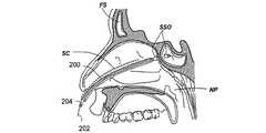
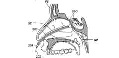
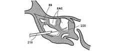
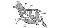
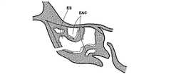
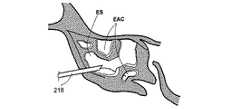
本特許出願における図面は、耳鼻咽喉の解剖学的構造を示すものである。通常、これらの解剖学的構造は、以下の符号が付されている。
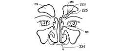
鼻腔NC、鼻咽腔NP、前頭洞FS、篩骨洞ES、篩骨蜂巣EAC、ちょう形骨洞SS、ちょう形骨洞口SSO、上顎洞MS、粘液嚢胞MC。The drawings in this patent application show the anatomical structure of the ENT. Typically, these anatomical structures are labeled with the following symbols:
Nasal cavity NC, nasopharyngeal NP, frontal sinus FS, ethmoid sinus ES, ethmoid honeycomb EAC, sphenoid sinus SS, sphenoid sinus SSO, maxillary sinus MS, mucous cyst MC.
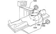
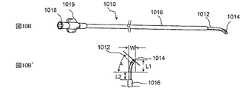
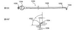
図1及び1Aは、低侵襲的外科システムを全体的に示す図である。同システムは、第1の案内装置1002(例、案内カテーテルや案内チューブ)、第2の案内装置1004(例、案内ワイヤや長手方向に延びるプローブ)、及び、機能装置1006(例、バルーンカテーテル、その他の膨張カテーテル、辺縁切除器具、切除器具等)を透視するために使用されるCアーム型X線透視装置から構成される。図2A乃至8Eは、本発明において使用可能である案内装置1002(例、案内カテーテルや案内チューブ)、1004(案内部、案内ワイヤ、長手のプローブ等)、及び、機能装置1006(例、バルーンカテーテル、その他の膨張カテーテル、辺縁切除器具、切除器具等)の例を示す図であるが、これらに限定されるものではない。装置1002、1004、1006は、Cアーム型X線透視装置が処置において同装置1002、1004、1006の位置を撮像し、モニターすることができるように放射線不透過性であってもよく、放射線不透過性のマーカーを含んでもよい。 1 and 1A generally illustrate a minimally invasive surgical system. The system includes a first guide device 1002 (eg, a guide catheter or guide tube), a second guide device 1004 (eg, a guide wire or a longitudinally extending probe), and a functional device 1006 (eg, a balloon catheter, Other dilatation catheters, marginal excision instruments, excision instruments, etc.) are used to form a C-arm type X-ray fluoroscopy device used to see through. FIGS. 2A-8E show a guide device 1002 (eg, guide catheter or guide tube), 1004 (guide section, guide wire, longitudinal probe, etc.) and functional device 1006 (eg, balloon catheter) that can be used in the present invention. , Other dilatation catheters, marginal excision instruments, excision instruments, etc.), but are not limited thereto. The
X線撮像装置の使用に加えて、或いは、別例として、装置1002、1004、1006は、FESSの処理において耳鼻咽候科医によって使用される通常の堅固な、或いは、可撓性を備えた内視鏡や立体内視鏡のような一つ以上の内視鏡装置を組み込んだり、組み合わせて使用してもよい。また、実施例において、放射線不透過性による撮像及び/又は内視鏡による可視化に加えて、或いは、これらに代えて、装置1002、1004、1006は、同装置1002、1004、1006が撮像外科手術案内システムやその他の電子解剖の写像又は案内システムと組み合わせて使用可能となるように、センサを組み込んでもよい。これらのシステムには、BrainLAB社の登録商標であるVectorVision、CASurgica社の登録商標であるHipNav、CBYON社の登録商標であるCBYON Suite、GE Medical社の登録商標であるInstaTrak、FluoroTrak、ENTrak、Medtronic社の登録商標であるStealthStation Treon、iOn、Medivision、Orthosoft社の登録商標であるNavitrack、Radionics社の登録商標であるOTS、Siemens社の商標であるVISLAN、Stryker Leibinger社の登録商標であるStryker Navigation System、Z−Katインコーポレイテッドの登録商標であるVoyager、Z−Box、並びに、Johnson&Johnson社の登録商標であるNOGAシステム及びCARTOシステムが含まれるが、これらに限定されるものではない。市場において販売されている診療ナビゲーションシステムは、装置及び方法と組み合わせて使用されてもよい。 In addition to or as an alternative to the use of X-ray imaging devices, the
更に、蛍光透視法によらない診療撮像技術としてB.Braun Aesculap社の登録商標であるOrthoPilot、Odin Medical Technologies社の登録商標であり、Medtronic社により販売されるPoleStar、MISON社の登録商標であるSonoDoppler、SonoWand、UltraGuide社の登録商標であるCT Guide、US Guide等があげられるがこれらに限定されるものではない。これらもまた装置及び方法と組み合わせて使用されてもよい。仮にカテーテルがシステムと好適に相互作用するように変更される場合、磁気共鳴による案内も実現可能である。 Further, as a medical imaging technique not based on fluoroscopy, B.I. OrthoPilot, a registered trademark of Braun Aesculap, registered trademark of Odin Medical Technologies, PoleStar, a trademark of MISON, and SonoGunde, a registered trademark of MISON. Although Guide etc. are mention | raise | lifted, it is not limited to these. These may also be used in combination with the apparatus and method. If the catheter is modified to interact favorably with the system, magnetic resonance guidance is also feasible.
本発明の装置及び方法は、耳鼻咽頭内の洞開口部やその他の通路への接触及び膨張や変形に関するものと評価される。これらの装置及び方法は、単独で使用されても、その他の外科的または非外科的治療と組み合わせて使用されてもよい。これらは、2004年8月4日付けの名称が「副鼻腔炎及びその他の疾患を治療するよう薬物及びその他の物質を搬送するための移植可能な装置及び方法」である係属中の米国特許出願第10/912578号明細書に開示されるような装置の及び薬物やその他の物質の搬送や移植を含むが、これらに限定されるものではない。米国特許出願第10/912578号は、その全体がここで開示されたものとする。 The apparatus and method of the present invention is evaluated for contact with sinus openings and other passageways in the otolaryngology and for expansion and deformation. These devices and methods may be used alone or in combination with other surgical or non-surgical treatments. These are pending US patent applications dated August 4, 2004, entitled “Implantable Devices and Methods for Delivering Drugs and Other Substances to Treat Sinusitis and Other Diseases” This includes, but is not limited to, the delivery of devices and the delivery and implantation of drugs and other materials as disclosed in US Ser. No. 10/912578. US patent application Ser. No. 10 / 912,578 is hereby incorporated in its entirety.
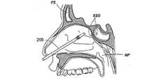
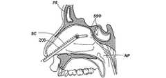
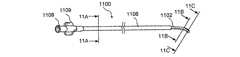
図2A乃至2Dは、案内カテーテルを使用して副鼻腔に接触する方法の様々な工程を示す人の頭部の矢状部分断面図である。図2Aにおいて、案内カテーテル200の形状における第1の案内装置が、鼻孔及び鼻腔NCを通過して、ちょう形骨洞SSのちょう形骨洞口SSO近傍の位置まで案内される。案内カテーテル200は、可撓性を有する。可撓性を備えた装置とは、1インチ(2.54cm)の装置の長さに対して約200重量ポンド以下の曲げ剛性を備える装置とする。案内カテーテル200は、直線的であっても一つ以上の湾曲部や屈曲部を組み込んでもよい。案内カテーテル200が湾曲したり屈曲している実施例において、湾曲や屈曲の偏向角度は、135°以下の範囲内にある。案内カテーテル200の湾曲部や屈曲部により形成される偏向角度の具体例として、0°、30°、45°、60°、70°、90°、120°、135°が挙げられる。 2A-2D are sagittal partial cross-sectional views of a person's head showing various steps of a method for contacting a sinus using a guide catheter. In FIG. 2A, a first guide device in the form of a
案内カテーテル200は、登録商標であるPebax、ポリイミド、網目状のポリイミド、ポリウレタン、ナイロン、ポリ塩化ビニル、登録商標であるHytrel、高密度ポリエチレン、ポリエーテルエーテルケトン、ステンレス鋼のような金属、並びに、PTFE、PFA、FEP及び延伸多孔質PTFE等のフッ素重合体のような好適な要素から構成可能である。案内カテーテル200は、様々な表面のコーティングを有する。例えば、親水性のつるつるしたコーティング、疎水性のつるつるしたコーティング、耐摩耗コーティング、耐穿刺コーティング、導電性又は伝熱性コーティング、放射線不透過性コーティング、音響発生コーティング、血栓形成減少コーティング、及び薬物投下コーティングである。図2Bにおいて、案内ワイヤ202から構成される第2の案内装置は、第1の案内装置(例、案内カテーテル200)を介して導入され、これにより、案内ワイヤ202は、開口部SSOを通過してちょう形骨洞SSに進入する。案内ワイヤ202は、心臓病学の技術において周知の方法により構成されてコーティングされる。図2Cにおいて、例えばバルーンカテーテルのような作業装置204は、案内ワイヤ202を覆ってちょう形骨洞SS内に案内される。図2Dにおいて、その後、作業装置204は、診断や治療をするために使用される。図2Dに明示するように、本具体例における処置は、ちょう形骨洞口SSOを膨張させることである。
しかしながら、本発明は、副鼻腔口やその他の、鼻、副鼻腔、鼻咽腔やこれらに隣接する領域内において人工の又は自然に発生した組織上の開口部や通路を膨張させたり変更したりすることにも使用可能であると評価される。処置の完了後、案内カテーテル200、案内ワイヤ202、及び、作業装置204は、回収され取り払われる。当業者に評価されるように、本特許出願明細書において開示されるこの工程や別の工程においては、操作者は、その他のタイプのカテーテルや本発明によるカテーテルを付加的に前進させてもよく、案内ワイヤ202は、調整可能であるか、変形可能であるか、鍛造可能である。案内ワイヤ202は、内蔵型内視鏡やその他のナビゲーション、或いは、撮像様式から構成されてもよい。これらは蛍光透視法、X線撮影法、超音波、高周波による局在、電磁気、磁気、自動装置の、及び、その他の放射エネルギーベースの様式を含むが、これらに限定されるものではない。このことに関して、図面は、波線で任意のスコープSCを示す。これらの任意のスコープSCは、好適なタイプの堅固な、或いは、可撓性を備えた内視鏡であってもよく、本発明の作業装置及び/又は案内装置とは分離させても内部に組み込んでもよいものといえる。 However, the present invention may inflate or modify artificial or naturally occurring tissue openings or passages in the sinus ostium and other areas of the nose, sinuses, nasopharynx and adjacent areas. It is evaluated that it can also be used. After the procedure is completed, the
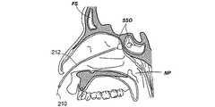
図2E乃至図2Hは、調整可能なカテーテルを使用して副鼻腔に接触する方法の様々な工程を示す人の頭部の矢状部分断面図である。図2Eにおいて、調整可能なカテーテル206の形態の案内装置が鼻孔に導入される。市場において販売されている装置は、副鼻腔における本技術に従って設計されているものではなく、容易に使用できるものではないが、ここで開示されるものに類似の機能を備える調整可能な先端部を有する装置の例をあげると、カリフォルニア州フリーモントにあるCardimaインコーポレイテッドにより製造される登録商標名Naviport、Medtronic社により製造される登録商標名Attain Prevail及びAttain Deflectableカテーテル、St.Jude Medical インコーポレイテッドにより製造される登録商標名Livewire Steerable Catheter、ボストンサイエンティフィック社により製造される登録商標名Inquiry Steerable Diagnostic Catheter、EBI社により製造される登録商標名TargetCath、Intraluminal Therapeuticsインコーポレイテッドにより製造される登録商標名Safe−Steerカテーテル、Catheter Researchインコーポレイテッドにより製造されるCynosar、Cordisコーポレーションにより製造されるTorque Control Balloon Catheter、及び、イスラエルのA,M.I. Technologies リミテッドにより製造されるDynamicDeca Steerable CatheterとDynamic XT Steerable Catheterであるが、これらに限定されるものではない。調整可能なカテーテル206は、基端部、末端部、並びに、同基端部及び末端部の間における操作により変形可能な部分から構成される。 2E through 2H are sagittal partial cross-sectional views of a person's head showing various steps of a method for contacting the sinuses using an adjustable catheter. In FIG. 2E, a guide device in the form of an
図2Fにおいて、調整可能なカテーテル206は、鼻の組織において、同調整可能なカテーテル206の末端部がちょう形骨洞SSのちょう形骨洞口SSOの近傍に配置されるように調整される。図2Gにおいて、バルーンカテーテル208の形態の作業装置が、調整可能なカテーテル206を介して案内されて、ちょう形骨洞口SSOを通過してちょう形骨洞SS内に進入する。その後、バルーンカテーテル208は、同バルーンカテーテルのバルーンがちょう形骨洞口SSO内に配置されるように調整される。図2Hにおいて、バルーンカテーテル208は、開口部SSOを膨張させるために使用される。この工程が完了すると、調整可能なカテーテル206及びバルーンカテーテル208は、鼻の組織から取り除かれる。本例において、調整可能なカテーテル206の形態の第1の案内装置のみが作業装置(本例においてはバルーンカテーテル208)の好適な案内及び手術上の配置のために使用される。しかしながら、処置の別例においては、第2の案内装置(例、長尺上の案内部材、案内ワイヤ、長尺上のプローブ等)が調整可能なカテーテル206の管腔を介して挿入され、作業装置208が同第2の案内装置上を所望の手術上の部位に案内される。 In FIG. 2F, the
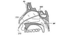
図2I乃至2Lは、所定の形状を有する案内ワイヤの形態の案内装置を使用して副鼻腔に接触する方法の様々な工程を示す人の頭部の矢状部分断面図である。図2Iにおいて、所定の形状を有する案内ワイヤ210の形態の案内装置が、鼻腔内に案内される。案内ワイヤ210は、基端部及び末端部から構成され、鼻の組織において、容易に案内できる形状に形成されている。実施例において、案内ワイヤ210は、略直線的である。別例において、案内ワイヤ210は、基端部及び末端部の間の傾斜、湾曲又は屈曲した部分から構成される。傾斜、湾曲又は屈曲した部分の偏向角度の例として、0°、30°、45°、60°、70°、90°、120°及び135°が挙げられる。図2Jにおいて、案内ワイヤ210は、同案内ワイヤの末端の先端部がちょう形骨洞口SSOを通過してちょう形骨洞SSに進入するように鼻の組織を通過する。図2Kにおいて、バルーンカテーテル212の形態の作業装置は、案内ワイヤ210に沿ってちょう形骨洞SS内に案内される。 FIGS. 2I to 2L are sagittal partial cross-sectional views of a person's head showing various steps of a method for contacting the sinuses using a guide device in the form of a guide wire having a predetermined shape. In FIG. 2I, a guide device in the form of a
通常、後述するように、作業装置は、案内ワイヤ212上の作業装置212を容易に進入させることができるように、診療医療の技術において周知のような、少なくとも作業装置212の一部を貫通するか、一部内又は一部上に形成される案内ワイヤ管腔を有する。その後、バルーンカテーテル212の位置は、バルーンカテーテルのバルーンがちょう形骨洞口SSO内となるように調整される。本出願明細書において開示されるように、バルーンカテーテル212は、放射線不透過性であるか、一つ以上の可視の又は撮像可能なマーカーやセンサを備える。図2Lにおいて、バルーンカテーテル212は、ちょう形骨洞口SSOを膨張させるために使用される。この工程が完了した後、案内ワイヤ210及びバルーンカテーテル212は、鼻組織から取り払われる。 Typically, as will be described below, the working device penetrates at least a portion of the working
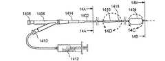
実施例において、バルーンカテーテル212は、具体化できるか、適応できる。図2M乃至2Oは、操作ワイヤを末端部に備えるバルーンカテーテルを使用して副鼻腔に接触する方法の様々な工程を示す人の頭部の矢状部分断面図である。図2Mにおいて、基端部及び末端部を有するバルーンカテーテル1214を備える作業装置は、鼻腔内に案内される。バルーンカテーテル214は、末端部において操作ワイヤ216を備える。図2Nにおいて、バルーンカテーテル214は、鼻組織を通過して、ちょう形骨洞口SSOを介してちょう形骨洞SS内に進入する。その後、バルーンカテーテル214の位置は、バルーンカテーテルのバルーンがちょう形骨洞口SSO内にとなるように調整される。図2Oにおいて、バルーンカテーテル214は、ちょう形骨洞口SSOを膨張させるために使用される。この工程の完了後、バルーンカテーテル214は、鼻組織から取り払われる。 In embodiments, the
実施例において、操作ワイヤ216は、バルーンカテーテル214内において後退されるか、バルーンカテーテル214から前進される。操作ワイヤの後退や前進は、親指ホイール、スライド、電気モータに取り付けられたボタン、トリガー等のような様々な手段により操作される。別例において、操作ワイヤ216は、装置や、診断用又は治療用の薬を案内するか取り払うことができるように、中空であるか、一つ以上の管腔を備える。その例が、2004年8月4日付けで出願された、発明の名称が「薬品及びその他の物質を搬送するための装置及び方法」である米国特許出願第10/912578号明細書に開示され、その全体が個々で開示されたものとする。 In embodiments, the
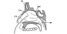
図2P乃至2Xは、未処置の、或いは、処置により形成された篩骨洞の開口部を介して篩骨洞ESに接触する方法の様々な工程を示す人の頭部の矢状部分断面図である。図2Pにおいて、案内カテーテル218の形態の案内装置は、篩骨洞ES内に案内される。篩骨洞ESは、多くの篩骨蜂巣EACから構成される。図2Qにおいて、案内ワイヤ220は、案内カテーテルを介して第1のEAC内に案内される。図2Rにおいて、その後、バルーンカテーテル222は、案内ワイヤ220上を介して第1のEAC内に案内される。図2Sにおいて、バルーンカテーテル222は、ESの組織を膨張させるために膨張される。図2Tにおいて、案内カテーテル218、案内ワイヤ220及びバルーンカテーテル222は、ES内に第1の新しい通路を残したまま取り払われる。ES内に新しく形成された通路により、ESを通過する粘液の排出が容易になる。図2Uでは、これに代えて、バルーンカテーテル222のみが取り払われる。案内カテーテル218の位置が調整されて、案内ワイヤ220が第2のEAC内に導入される。図2Vにおいて、バルーンカテーテル222は、案内ワイヤ220上を介して第2のEAC内に導入される。図2Wにおいて、バルーンカテーテル222は、ESの組織を膨張させるために膨張される。図2Xにおいて、案内カテーテル218、案内ワイヤ220及びバルーンカテーテル222は、ES内に第2の新しい通路を残したまま取り払われる。ES内の第2の新しい通路により、ESを通過する粘液の排出は更に容易になる。ESの組織を膨張させるこの方法は、ES内に多くの新しい通路を形成するために繰り返されてもよい。 2P-2X are sagittal partial cross-sectional views of a person's head showing various steps of the method of contacting the ethmoid sinus ES through an opening of the ethmoid sinus that is untreated or formed by treatment. It is. In FIG. 2P, a guide device in the form of a
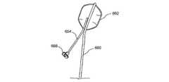
図2Y乃至2ACは、前頭洞FS内の粘液嚢胞を処置する方法の様々な工程を示す、人間の頭部の前頭面の部分図である。図2Yにおいて、案内カテーテル224の形態の案内装置が、鼻腔NCを介して前頭洞FS内に案内される。前頭洞FSは、処置すべき粘液嚢胞MCを有する。図2Zにおいて、先鋭端228を備える貫通装置226は、洞貫通装置226がMCを少なくとも部分的に貫通するように、案内カテーテル224を介して案内される。図2AAにおいて、バルーンカテーテル230は、貫通装置226上を介してMC内に案内される。図2ABにおいて、その後、バルーンカテーテル230は、MCが破裂してMCの中身が排出されるように、膨張される。図2ACにおいて、貫通装置226及びバルーンカテーテル230が取り払われる。 2Y-2AC are partial views of the frontal surface of the human head showing the various steps of the method for treating mucus cysts in the frontal sinus FS. In FIG. 2Y, a guiding device in the form of a guiding
ここで開示される方法は、鼻腔内、副鼻腔内、鼻咽腔内や、周辺の組織内の組織を清掃や洗浄する工程からも構成される。例えば、潅注や吸引によるがこれらに限定されるものではない。診断や治療の工程に先だって、或いは、後に、目的の組織を清掃する工程が行われる。 The method disclosed herein also includes a step of cleaning or washing tissue in the nasal cavity, sinuses, nasopharynx, and surrounding tissues. For example, by irrigation or suction, but not limited thereto. Prior to or after the diagnosis or treatment process, a process of cleaning the target tissue is performed.
本発明の方法は、処置のために、鼻、副鼻腔、鼻咽腔や、周辺の組織を前処置する工程からも構成される。例えば、鼻組織を収縮させるための血管収縮剤(例、0.025%乃至0.5%のフェニレフリンや塩酸オキシメタゾリン(ネオシネフリンや登録商標であるアフリン))、組織等を浄化するための抗菌剤(例、ポビドンヨード(登録商標であるBetadine))等の噴霧や洗浄である。 The method of the present invention also comprises the step of pretreating the nose, sinuses, nasopharynx and surrounding tissues for treatment. For example, a vasoconstrictor for contracting nasal tissue (eg, 0.025% to 0.5% phenylephrine or oxymetazoline hydrochloride (neocinephrine or registered afrin)), tissue purification, etc. Spraying or washing with an antibacterial agent (eg, povidone iodine (registered trademark Betadine)).
図3A乃至3Cは、人工的に形成された副鼻腔の開口部を介して同副鼻腔に接触する方法の様々な工程を示す、人間の頭部の前頭面の部分図である。図3Aにおいて、穿刺装置300が、鼻孔を介して挿入され、上顎洞MS内に人工の開口部を形成するために使用される。穿刺装置としては、針、湾曲した柄を備える針、解剖器具、パンチ、ドリル、コアラ、外科用メス、バー、鋏、鉗子及びカッターを含む針類のような周知のものがあげられる。図3Bにおいて、穿刺装置300が取り払われ、例えばバルーンカテーテル302のような作業装置が、人工の開口部を介して上顎洞内に案内される。図3Cにおいて、バルーンカテーテル302は、上顎洞内に人工的に形成された開口部を膨張させるために使用される。 FIGS. 3A-3C are partial views of the frontal surface of a human head showing the various steps of the method of contacting the sinus via an artificially formed sinus opening. In FIG. 3A, a
この工程の後、バルーンカテーテル302は、取り払われる。実施例において、穿刺装置300は、案内装置(例、案内ワイヤやその他の長手のプローブや部材)が貫通する管腔を備え、上顎洞内に挿入されてもよい。同穿刺装置300は、その後、このような案内装置(例、案内ワイヤやその他の長手のプローブや部材)を配置して取り払われてもよい。このような事例において、作業装置(例、バルーンカテーテル302)は、同作業装置(例、バルーンカテーテル302)が前処置により挿入された案内装置(例、案内ワイヤやその他の長手のプローブや部材)上を介して進入できるように、管腔やその他の組織を備えてもよい。 After this step, the
上述した方法においては、バルーンカテーテルは、例示として使用されるに過ぎず、本発明において別の作業装置が使用可能である。図4Aは、3つの組の膨張具、即ち、第1の組の膨張具402、第2の組の膨張具404、及び、第3の組の膨張具406の組み合わせから構成される作業装置の例を示す断面図である。第3の組の膨張具406の直径D3は、第2の組の膨張具404の直径D2より長く、同直径D2は、第1の組の膨張具402の直径D1より長い。組の膨張具は、1つ以上の湾曲、或いは傾斜した部分を備える。組の膨張具は、ステンレス鋼316のような生体適合性を備える様々な材料から形成される。その他の様々な金属、ポリマー、及び、材料も、組の膨張具を形成するために使用可能である。 In the method described above, the balloon catheter is only used as an example, and another working device can be used in the present invention. FIG. 4A shows a working device comprised of a combination of three sets of expanders: a first set of
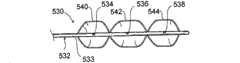
図4B乃至4Eは、圧力により膨張可能なステントを備えるバルーンカテーテルから構成される作業装置を使用して鼻腔を膨張させる方法の様々な工程を示す図である。図4Bにおいて、例えば案内ワイヤ416のような案内装置が、例えば副鼻腔の開口部のような鼻腔内に案内される。図4Cにおいて、バルーンカテーテル418が案内ワイヤ416上を介して鼻腔内に案内される。バルーンカテーテル418は、圧力により膨張可能なステント420から構成される。バルーンカテーテル418の位置は、圧力により膨張可能なステント420が、同圧力により膨張可能なステントが配置される目的の組織において、内部に位置するように調整される。図4Dにおいて、バルーンカテーテル418のバルーンは、膨張されて、圧力により膨張可能なステント420を配置する。図4Eにおいて、バルーンカテーテル418は、圧力により膨張可能なステント420を鼻腔内に残したまま取り払われる。 4B-4E illustrate various steps of a method for inflating the nasal cavity using a working device comprised of a balloon catheter with a stent that is expandable by pressure. In FIG. 4B, a guide device, such as a
金属チューブ設計、ポリマーチューブ設計、連鎖設計、ロールシート設計、1つのワイヤ設計等、各種のタイプのステントの設計が、ステント420を構成するために使用可能である。これらの設計はオープンセルやクローズドセルの構造を有する。ステント420の製造には、金属やポリマー要素のレーザー切断、金属要素の溶接等を含む様々な製造方法が適用可能であるが、これらに限定されるものではない。ステント420の製造には、金属、ポリマー、フォームタイプの材料、塑性的に変形可能な材料、超弾性を備えた材料等様々な材料が使用可能であるが、これらに限定されるものではない。ステントを形成するために使用可能である材料として、例えば登録商標がSilasticであるシリコン、ポリウレタン、ゲルフィルム及びポリエチレンがあげられるが、これらに限定されるものではない。ステント420には、放射線不透過性コーティング、薬物溶出機構等を含む様々な特徴が付加されるがこれらに限定されるものではない。 Various types of stent designs can be used to construct the
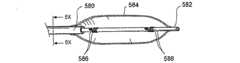
図4Fは、実施例における側面開口部426が形成された装置本体424から構成される側面吸引及び/又は切断装置422を備える作業装置の部分斜視図である。切断装置422は、鼻孔、鼻腔、開口部、小口、副鼻腔の内部等のような通路内に挿入されて、側面開口部426が切除される部位(例、ポリープ、損傷部位、残屑、組織、凝血部位等)に隣接するように、配置される。切断装置422は、回転されて側面開口部426内に配置された組織を切断する。切断装置422は、側面開口部426を関係する組織の部位と対向させる可撓性を備えた先端部や湾曲した末端部を備えてもよい。更に、この切断装置422は、同切断装置422の一方の側上に組み込まれる任意の安定化バルーンを備えてもよい。これにより、切断装置422は、関係する組織の部位に対して押圧される。切断装置422は、更に、超音波、ファイバーやデジタル光学素子、OCT、RFや、電磁センサやエミッタ等のような1つ以上の実装された撮像様式を含んでもよい。 FIG. 4F is a partial perspective view of a working apparatus including a side suction and / or cutting
図4Gは、実施例における、組織を切除する回転するカッター装置を備える作業装置の部分斜視図である。回転するカッター装置428は、案内装置432内に設けられる回転部材430から構成される。回転部材430は、回転部材430の末端領域の近傍に設けられる回転刃434から構成される。回転刃434は、回転部材430内において後退可能である。回転カッター装置428は、鼻孔、鼻腔、開口部、小口、副鼻腔の内部等のような通路436内に挿入され、回転刃434が取り払われる部位(例、ポリープ、損傷部位、残屑、組織、凝血部位等)に隣接するように配置される。その後、回転部材430は、回転し、回転刃434により組織が切除される。実施例において、回転部材430は、案内装置432内に後退可能である。別例において、回転カッター装置428は、同回転カッター装置428の末端部近傍に、吸引や潅注のための機構を備える。 FIG. 4G is a partial perspective view of a working device including a rotating cutter device for excising tissue in the embodiment. The
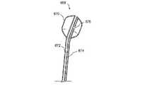
図4H及び4Iは、機械的膨張具408を備える作業部材を使用して鼻腔を膨張させる方法の様々な工程を示す図である。機械的膨張具408は、外側部材410、内部材412、及び、1つ以上の長手の湾曲可能な部材414から構成される。内部材412は、外側部材410内を摺動可能である。湾曲可能な部材414の基端部は、外側部材410の末端部に取り付けられ、湾曲可能な部材414の末端部は、内部材412の末端部に取り付けられる。図4Hにおいて、機械的膨張具408は、例えば、副鼻腔の小口のような鼻組織内の開口部内に挿入される。機械的膨張具408は、湾曲可能な部材414が鼻組織の開口部内にくるように、開口部内に配置される。 4H and 4I illustrate various steps of a method for inflating the nasal cavity using a working member comprising a
図4Iにおいて、外側部材410及び内部材412の相互作用により、外側部材410の末端部が内部材412の末端部近傍にくる。これにより、湾曲可能な部材414は、機械的膨張具408の末端領域の直径が増加するように湾曲する。従って、湾曲可能な部材414は、鼻組織における開口部と接触し、圧力を径方向にかけて同開口部を膨張させる。外側部材410、内部材412、及び、湾曲可能な部材414のような機械的膨張具408の様々な要素は、ステンレス鋼316のような好適な生体適合性材料から形成可能である。その他の様々な金属、ポリマー、及び、材料も膨張具408の様々な要素を構成するために使用可能である。実施例において、外側部材410は、略堅固であり、内部材412は、可撓性を備える。外側部材410は、略直線的であってもよく、1つ以上の屈曲したり湾曲した領域から構成されてもよい。内部材412は、1つ以上の管腔を備える。 In FIG. 4I, due to the interaction between the
図4J及び4Kは、ネジ機構を備える機械的膨張具の設計を示す斜視図である。図4Jは、外側部材438及び内部のネジ部材440を備える機械的膨張具を示す図である。内部のネジ部材440は、外側部材438の末端部に設けられる第1のピボット442を介して外側部材438に連結される。内部のネジ部材440の末端部は、第2のピボット444に連結される。機械的膨張具は、更に、1つ以上の湾曲可能な部材446から構成される。湾曲可能な部材446の末端部は第2のピボット444に取り付けられ、湾曲可能な部材446の基端部は第1のピボット442に取り付けられる。図4Kにおいて、内部のネジ部材440は、一方向に回動される。これにより、第2のピボット444は、第1のピボット442の近傍にくる。これにより、湾曲可能な部材446は、径方向に力を発揮しながら湾曲する。この力は、組織の部位の膨張や置き換えのために使用可能である。外側部材438は、略直線的であってもよく、1つ以上の湾曲した、或いは、傾斜した領域を備えてもよい。内部のネジ部材440は、1つ以上の管腔を備える。 4J and 4K are perspective views showing the design of a mechanical inflator with a screw mechanism. FIG. 4J shows a mechanical expander comprising an
図4L及び4Mは、押圧可能な部材を備える機械的膨張具の設計の断面図である。図4Lは、外側部材448を備える機械的膨張具を示す図である。外側部材448は、同外側部材448の末端部上に1つ以上の湾曲可能な領域449を備える。機械的膨張具は、内部の押圧可能な部材450を更に備える。内部の押圧可能な部材450は、同内部の押圧可能な部材450の末端部上に拡張領域452を備える。図4Mにおいて、内部の押圧可能な部材450は、末端方向に押圧される。これにより、湾曲可能な領域449上に径方向の力が発揮され、同湾曲可能な領域449は、径方向に力を発揮しながら径方向に湾曲する。この力は、組織の部位を膨張したり、置き換えたりすることに使用可能である。外側部材448は、略直線的であってもよく、1つ以上の湾曲或いは傾斜した領域を備えてもよい。内部の押圧可能な部材450は、1つ以上の管腔を備える。 4L and 4M are cross-sectional views of a mechanical expander design with a pressable member. FIG. 4L shows a mechanical inflator with an
図4N及び4Oは、張引可能な部材を備える機械的膨張具の設計の断面図である。図4Nは、外側部材454を備える機械的膨張具を示す図である。外側部材454は、同外側部材454の末端部上に1つ以上の湾曲可能な領域456を備える。機械的膨張具は、内部の張引可能な部材458を更に備える。内部の張引可能な部材458は、同内部の張引可能な部材458の末端部上に拡張領域460を備える。図4Oにおいて、内部の張引可能な部材458は、基端方向に張引される。これにより、湾曲可能な領域456上に径方向に作用する力が発揮され、同湾曲可能な領域456は、径方向に力を作用させながら径方向に湾曲する。この力は、組織の部位を膨張したり、置き換えたりすることに使用可能である。外側部材454は、略直線的であってもよく、1つ以上の湾曲した、或いは、傾斜した領域を備えてもよい。内部の張引可能な部材458は、1つ以上の管腔を備える。 4N and 4O are cross-sectional views of a mechanical expander design with a tensionable member. FIG. 4N shows a mechanical inflator with an
図4P及び4Qは、ヒンジ部材を備える機械的膨張具の設計の断面図である。図4Pは、外側部材462を備える機械的膨張具を示す図である。外側部材462は、同外側部材462の末端部上に1つ以上の湾曲可能な領域464を備える。機械的膨張具は、外側部材462内部に設けられる内部材466を更に備える。実施例において、内部材466は、管状である。内部材466の末端部は、1つ以上の第1のヒンジ部468を備える。第1のヒンジ部468は、1つ以上の作動要素470の基端部にヒンジにより取り付けられる。作動要素470の末端部は、外側部材462の内表面上に位置する1つ以上の第2のヒンジ472に取り付けられる。図4Qにおいて、内部材466は、末端方向に押圧される。これにより、作動要素470は、湾曲可能な領域464上に径方向の力を発揮する。すると、湾曲可能な領域464は、径方向の力により径方向に湾曲する。この径方向の力は、組織の部位を膨張したり、置き換えたりすることに使用可能である。外側部材462は、略直線的であってもよく、1つ以上の湾曲した、或いは、傾斜した領域を備えてもよい。内部材466は、1つ以上の管腔を備える。 4P and 4Q are cross-sectional views of a mechanical expander design comprising a hinge member. FIG. 4P shows a mechanical inflator with an
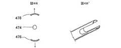
図4R乃至4Wは、図4H乃至4Qにおける機械的膨張具の構造の例を示す。図4Rは、内側部材474、外部の静止した部材476及び外部の湾曲可能な部材478から構成される機械的膨張具の断面図である。図4S’において、内側部材474が動作するときに発生する力により、外部の湾曲可能な部材478を径方向に移動させる。この力は、組織の部位を膨張、或いは置き換えるために使用可能である。この構造は、特定の径方向に力を発揮するために使用される。 4R-4W show examples of the structure of the mechanical inflator in FIGS. 4H-4Q. FIG. 4R is a cross-sectional view of a mechanical inflator composed of an
図4S’は、図4Rの外部の静止した部材476の部分斜視図である。図4Tは、内側部材480、第1の外部の半管状部材482及び第2の外部の半管状部材484から構成される機械的膨張具の断面図である。図4Uにおいて、内側部材480が動作する時に発生する力により、第1の外部の半管状部材482及び第2の外部の半管状部材484を径方向に移動させる。この力は、組織の部位を膨張、或いは、置き換えるために使用可能である。この構造は、二つの正反対の領域に力を発揮することに有効である。 4S 'is a partial perspective view of the outer
図4U’は、図4Tの第1の外部の半管状部材482及び第2の外部の半管状部材486の部分斜視図である。図4Vは、内側部材486、第1の外部の湾曲した部材488及び第2の外部の湾曲した部材490から構成される機械的膨張具の斜視図である。図4Wにおいて、内側部材486が動作する時に発生する力により、第1の外部の湾曲した部材488及び第2の外部の湾曲した部材490を径方向に移動させる。この力は、組織の部位を膨張、或いは、置き換えるために使用可能である。この構造は、2つの正反対の領域において狭小な方の領域上に力を作用させることに有効である。図4Wは、図4Vの第1の外部の湾曲した部材488及び第2の外部の湾曲した部材490の部分斜視図である。図4H乃至4Qにおける機械的膨張具の同様な設計が、3つ以上の置き換え可能な部材を使用して可能となる。ここで開示される機械的膨張具における内側部材は、外側の部材を置き換えて径方向に力を作用させるために、バルーンに代えてもよい。 4U 'is a partial perspective view of the first outer
作業装置のその他の設計として、カッター、歯、回転ドリル、回転刃、先細の膨張具、パンチ、解剖器具、バー、非膨張の機械的に拡張可能な部材、高周波の機械的バイブレーター、高周波の切除装置、マイクロ波の切除装置、レーザー装置(例、CO2、アルゴン、チタン燐酸カリウム、ホルミウムのYAGレーザー装置、ニッカドのYAGレーザー装置)、シュリンゲ、生検器具、診断のための、或いは、治療のための薬物を案内するスコープ及び装置も使用可能であるが、これらに限定されるものではない。 Other work equipment designs include cutters, teeth, rotary drills, rotary blades, tapered expanders, punches, dissecting instruments, bars, non-inflatable mechanically expandable members, high-frequency mechanical vibrators, high-frequency ablation Devices, microwave ablation devices, laser devices (eg, CO2, argon, potassium titanium phosphate, holmium YAG laser devices, NiCd YAG laser devices), shringe, biopsy instruments, for diagnosis or for treatment Scopes and devices for guiding other drugs can also be used, but are not limited thereto.
図5Aは、実施例における、円錐形の基端部、円錐形の末端部、及び、同円錐形の基端部及び円錐形の末端部の間の円筒状部から構成されるバルーンを示す斜視図である。図5B乃至5Nは、バルーンの別例を示す斜視図である。図5Bは、円錐形のバルーン、図5Cは、球形のバルーン、図5Dは、円錐形及び長手方向に延びる角柱からなるバルーン、図5Eは、長手方向に延びる球形のバルーン、図5Fは、犬の骨型のバルーン、図5Gは、オフセットバルーン、図5Hは、角柱のバルーン、図5Iは、円錐形及び角柱からなるバルーン、図5Jは、円錐形及び長手方向に延びる球形からなるバルーン、図5Kは、先細のバルーン、図5Lは、段差を有するバルーン、図5Mは、円錐形かつオフセットのバルーン、図5Nは、湾曲したバルーンである。 FIG. 5A is a perspective view showing a balloon composed of a conical proximal end, a conical distal end, and a cylindrical portion between the conical proximal end and the conical distal end in the embodiment. FIG. 5B to 5N are perspective views showing other examples of the balloon. 5B is a conical balloon, FIG. 5C is a spherical balloon, FIG. 5D is a conical and longitudinally extending prism, FIG. 5E is a longitudinally extending spherical balloon, and FIG. 5F is a dog. 5G is an offset balloon, FIG. 5H is a prismatic balloon, FIG. 5I is a conical and prismatic balloon, FIG. 5J is a conical and longitudinally extending spherical balloon, FIG. 5K is a tapered balloon, FIG. 5L is a stepped balloon, FIG. 5M is a conical and offset balloon, and FIG. 5N is a curved balloon.
ここで開示されるバルーンは、生体適合性の材料から形成可能で、例えば、ポリエチレンテレフタレート、ナイロン、ポリウレタン、ポリ塩化ビニル、架橋ポリエチレン、ポリオレフィン、HPTFE、HPE、LDPE、EPTFE、ブロック共重合体、ラテックス及びシリコンであるが、これらに限定されるものではない。 The balloons disclosed herein can be formed from biocompatible materials such as polyethylene terephthalate, nylon, polyurethane, polyvinyl chloride, cross-linked polyethylene, polyolefin, HPTFE, HPE, LDPE, EPTFE, block copolymers, latex. And silicon, but is not limited thereto.
ここで開示されるバルーンは、モールド成形、ブロー成形、浸漬成形、押し出し成形、等の様々な製造方法により製造可能であるが、これらに限定されるものではない。ここで開示されるバルーンは、食塩水、水、空気、X線撮影造影材料、診断のための或いは治療のための物質、超音波を発生する材料、及び、熱、冷気、或いは、電気を伝導する流体等様々な膨張する媒体により膨張可能であるがこれらに限定されるものではない。 The balloon disclosed here can be manufactured by various manufacturing methods such as molding, blow molding, dip molding, and extrusion molding, but is not limited thereto. The balloons disclosed herein conduct saline, water, air, radiographic contrast materials, diagnostic or therapeutic substances, materials that generate ultrasound, and heat, cold, or electricity. It can be expanded by various expanding media such as a fluid to be used, but is not limited thereto.
本発明のバルーンは、目的の組織に診断のための、或いは、治療のための物質を搬送するように変形されてもよい。例えば、図5Oは、実施例における、診断のための、或いは、治療のための物質を搬送するバルーンを備えるバルーンカテーテル装置500の部分斜視図である。バルーンカテーテル装置500は、バルーン504を載置する可撓性を備えたカテーテル502を備える。カテーテル装置500は、バルーン504を膨張させて、鼻孔、鼻腔、鼻道、小口、副鼻腔の内部等のような通路内に進入し、小口、通路、又は、膨張、拡張、或いは、圧縮(例、止血のために圧力をかける)される組織や部位に隣接した部位内に、膨張したバルーン504と共に配置される。その後、バルーン504は、膨張されて、小口、通路、組織や部位を拡張、或いは圧縮する。その後、バルーン504は収縮され、装置500は退去される。このバルーン504は、コーティング、浸漬されるか、同バルーンから隣接した組織に溶出する薬剤や物質を設けてもよい(例、隣接した組織を薬剤で浸漬したり、組織がバルーン504と接触するよう収縮させるために熱やその他のエネルギーを組織に放射する)。 The balloon of the present invention may be modified to deliver a diagnostic or therapeutic substance to the target tissue. For example, FIG. 5O is a partial perspective view of a
別例において、バルーンは複数の開口部を有し、同開口部を介して物質が搬送可能であり、圧力下において物質がバルーンに隣接した組織を浸漬、或いは、組織内に拡散するように、搬送可能である。別例において、放射性シード、繊維、リボン、気体や液体等がカテーテルシャフト502やバルーン504、或いは、全く別のカテーテル本体内に一定時間注入されて、隣接した組織を暴露し、所望の診断の、或いは、治療の効果を得る(例、組織収縮等)。 In another example, the balloon has a plurality of openings through which the substance can be transported so that, under pressure, the substance immerses or diffuses into the tissue adjacent to the balloon. It can be transported. In another example, radioactive seeds, fibers, ribbons, gases, liquids, etc. are infused into the
本発明におけるバルーンは、処置の診断の、或いは、治療の効果を高めるための様々な表面の特徴を有する。例えば、図5Pは、実施例における、バルーン510と1つ以上のカッター刃512を有する可撓性を備えたカテーテル508から構成されるバルーン又はカッターカテーテル装置506を示す部分斜視図である。装置506は、バルーン510を膨張させて、鼻孔、鼻腔、鼻道、小口、副鼻腔の内部等のような通路内に進入し、小口、通路、又は、膨張、拡張、或いは、圧縮される組織や部位に隣接した部位内に、膨張したバルーン510と共に配置され、消耗に応じて1つ以上の切断部や溝部を形成する(例、拡張時における組織の破断の制御し、組織の損傷を最小限にするために)。その後、バルーン510は、小口、通路、組織や部位を膨張、拡張や圧縮するために膨張し、これにより、カッター刃512が隣接した組織や部位において切断部を形成する。その後、バルーン510は収縮され、装置506は取り払われる。刃はモノポーラ、或いは、バイポーラRFエネルギーにより駆動され、又は、組織を切断するように過熱され、同時に、コラーゲン繊維やその他の連結する組織のタンパク質を熱収縮させ、軟骨を変形や軟化させる等して止血する。 The balloon in the present invention has various surface features to enhance the diagnostic or therapeutic effect of the treatment. For example, FIG. 5P is a partial perspective view of a balloon or
本発明のバルーンは、バルーン特性を高めるために様々な補強手段を有する。例えば、図5Q及び5Q’は、実施例における、1つ以上の補強部材520を上に載置するバルーン518を有する可撓性を備えたカテーテル516から構成されるバルーンカテーテル装置514の斜視図である。本実施例において、補強部材520は、バルーン518の外表面上に取り付けられた網部である。補強網部は、ポリマー繊維(例、PETや登録商標名ケブラー繊維)、金属繊維(例、SS316やニチノール繊維)、及び、金属や非金属の網やシートのような好適な材料から構成される。補強コーティング、外部又は内部の補強コイル、補強織物、補強網、補強ワイヤ、補強リング、バルーン材料等への埋め込み繊維を含むその他の様々な補強手段が使用可能であるが、これらに限定されるものではない。 The balloon of the present invention has various reinforcing means to enhance the balloon characteristics. For example, FIGS. 5Q and 5Q ′ are perspective views of a
図5Q”は、図5Q及び5Q’におけるバルーンカテーテルと共に使用可能な補強網部を示す斜視図である。本発明におけるバルーンは、バルーン特性を高めるための様々な防諜手段を有する。図5Rは、実施例における、シャフト524及びバルーン526を備えるバルーンカテーテル522の部分断面図である。シャフト524は、バルーン膨張管腔を備える。バルーン膨張管腔の末端部は、バルーン526の末端部の近傍に配置される膨張ポート528内において終端する。従って、バルーンカテーテル522が口部内に挿入されてバルーン526が膨張すると、バルーン526の末端部は、バルーンの基端部に先立って膨張する。これにより、バルーン526の口部外への滑落が抑止される。 Fig. 5Q "is a perspective view showing a reinforcing mesh that can be used with the balloon catheter in Figs. 5Q and 5Q '. The balloon in the present invention has various fenders to enhance the balloon properties. Figure 7 is a partial cross-sectional view of a
図5S乃至5Tは、多数のバルーンを備えるバルーンカテーテルの設計を示す図である。図5Sは、実施例における、管腔533を備えるシャフト532から構成されるバルーンカテーテル530を示す部分断面図である。管腔533は、シャフト532上に設けられた3つの口部、即ち第1の口部534、第2の口部536、第3の口部538に対して開口している。これらの3つの口部は、3つのバルーンを膨張させるために使用される。第1の口部534は第1のバルーン540を膨張させ、第2の口部536は、第2のバルーン542を膨張させ、第3の口部538は第3のバルーン544を膨張させる。実施例において、第1のバルーン540及び第3のバルーン544は、同一の管腔により膨張され、第2のバルーン542は、別の管腔により膨張される。別例において、第1のバルーン540、第2のバルーン、第3のバルーンが連通し、同一の管腔により膨張される。バルブ機構により第2のバルーンを膨張されるに先だって、第1のバルーン及び第2のバルーンを膨張させる。 FIGS. 5S-5T show the design of a balloon catheter with multiple balloons. FIG. 5S is a partial cross-sectional view showing a
これに代えて、バルーンは、個別の管腔によって膨張可能である。図5Tは、実施例における、第1の膨張管腔550、第2の膨張管腔552、第3の膨張管腔554から構成されるシャフト548を備えるバルーンカテーテル546の部分断面図である。これらの3つの膨張管腔は、3つの連通しないバルーンを膨張するために使用される。第1の膨張管腔550は、第1のバルーン556を膨張し、第2の膨張管腔552は、第2のバルーン558を膨張し、第3の膨張管腔554は、第3のバルーン560を膨張する。 Alternatively, the balloon can be inflated by a separate lumen. FIG. 5T is a partial cross-sectional view of a
ここで開示される装置は、1つ以上のナビゲーション、或いは、可視化の様式から構成されてもよい。図5U乃至5ABは、様々な実施例における、センサを備えるバルーンカテーテルの斜視図及び断面図である。図5Uは、外側部材562、内側部材564、並びに、外側部材562の末端領域及び内側部材564の末端領域に取り付けられるバルーン566から構成されるバルーンカテーテルを示す部分斜視図である。バルーンカテーテルは、更に、外側部材562の末端領域上に設けられる第1のセンサ568、及び、内側部材564の末端領域上に設けられる第2のセンサ570を備える。図5Vは、図5Uにおける5V−5V線に沿った断面図である。外側部材562は、第1のセンサ568からリード線を受領する第1のセンサ管腔572を備える。内側部材564は、第2のセンサ570からリード線を受領する第2のセンサ管腔574を備える。内側部材564は、更に、円形の管腔576を備える。外側部材562及び内側部材564は環状の管腔578を内包する。実施例において、環状の管腔578は、バルーン膨張管腔である。 The devices disclosed herein may be comprised of one or more navigation or visualization modes. 5U-5AB are perspective and cross-sectional views of a balloon catheter with a sensor in various embodiments. 5U is a partial perspective view showing a balloon catheter comprised of an
図5Wは、外側部材580、内側部材582、及び、同外側部材580の末端領域及び内側部材582の末端領域に取り付けられるバルーン584を備えるバルーンカテーテルを示す部分斜視図である。バルーンカテーテルは、更に、内側部材582の末端領域上に設けられる第1のセンサ586、及び、第1のセンサに対して末端側の内側部材582の末端領域上に設けられる第2のセンサ588を備える。図5Xは、図5Wにおける5X−5X線に沿った断面図である。内側部材582は、第1のセンサ586からリード線を受領する第1のセンサ管腔590、及び、第2のセンサ588からリード線を受領する第2のセンサ管腔592を備える。内側部材582は、更に、円形の管腔594を備える。外側部材580及び内側部材582は、環状の管腔596を内包する。実施例において、環状の管腔596は、バルーン膨張管腔である。 5W is a partial perspective view of a balloon catheter comprising an
図5Yは、外側部材598、内側部材600、及び、同外側部材598の末端領域及び内側部材600の末端領域に取り付けられるバルーン602を備えるバルーンカテーテルを示す部分斜視図である。バルーンカテーテルは、更に、外側部材598の末端領域上に設けられる第1のセンサ604、及び、第1のセンサに対して末端側の外側部材598の末端領域上に設けられる第2のセンサ606を備える。図5Zは、図5Yにおける5Z−5Z線に沿った断面図である。外側部材598は、第1のセンサ604からリード線を受領する第1のセンサ管腔608、及び、第2のセンサ606からリード線を受領する第2のセンサ管腔610を備える。内側部材600は、更に、円形の管腔612を備える。外側部材598及び内側部材600は、環状の管腔614を内包する。実施例において、環状の管腔614は、バルーン膨張管腔である。 FIG. 5Y is a partial perspective view showing a balloon catheter comprising an
センサからのリード線は、管腔内に内包されることなく、バルーンカテーテルの要素の表面上に取り付けられてもよい。図5AAは、外側部材616、内側部材618、及び、外側部材616の末端領域及び内側部材618の末端領域に取り付けられるバルーンを備えるバルーンカテーテルの部分斜視図である。バルーンカテーテルは、更に、外側部材616の末端部に設けられる第1のセンサ624、及び、内側部材618の末端領域に設けられる第2のセンサ626を備える。第2のセンサ626は、リード線628を備える。図5ABは、図5AAにおける5AB−5AB線に沿った断面図である。外側部材616は、第1のセンサ624からリード線を受領する第1のセンサ管腔630を備える。内側部材618は、円形の管腔632を備える。第2のセンサ626からのリード線628は、内側部材618の外表面上に取り付けられ、内側部材618に対して平行に指向する。外側部材616及び内側部材618は、環状の管腔634を内包する。実施例において、環状の管腔634は、バルーン膨張管腔である。図5U乃至5ABに示すセンサは、電磁センサや、例えば、位置センサ、磁気センサ、電磁コイル、RFトランスミッタ、ミニトランスポンダ、超音波感応又は放出鉱石、ワイヤマトリックス、マイクロシリコンチップ、光ファイバーセンサ等を含むセンサであるが、これらに限定されるものではない。 The lead from the sensor may be mounted on the surface of the balloon catheter element without being contained within the lumen. FIG. 5AA is a partial perspective view of a balloon catheter comprising an
図6A乃至6Gは、実施例における、ここで開示される様々な装置のためのシャフトの設計を示す部分斜視図である。これらのシャフトの設計は、高トルクや高破壊圧力を経験したり、高い押圧性、操作性、及び、捻れ耐性を必要とする装置に特に有効である。図6Aは、実施例における、シャフトの周囲に巻き付く螺旋要素604を備えるシャフト602を示す部分斜視図である。螺旋要素604は、金属(例SS316L、SS304)及びポリマーのような好適な材料から形成可能である。実施例において、螺旋要素604は、0.04mm乃至0.25mmの直径の円筒状のワイヤの形態である。別例において、螺旋要素は、0.03mm×0.08mm乃至0.08mm×0.25mmの範囲の断面の寸法を有する平坦なワイヤの形態である。 6A-6G are partial perspective views showing shaft designs for various devices disclosed herein in an embodiment. These shaft designs are particularly useful for devices that experience high torque and high burst pressure, or that require high pressability, operability, and torsional resistance. FIG. 6A is a partial perspective view showing a
図6Bは、実施例における、補強繊維608を備えるシャフト606を示す部分斜視図である。補強繊維608は、シャフト606の軸線に対して略平行に延びる。シャフト606は、補強繊維608と共に外被層により覆われてもよい。補強繊維608は、金属、ポリマー、グラスファイバー等のような好適な材料から形成可能である。補強繊維608は、形状記憶特性を有してもよい。実施例において、補強繊維608は、シャフト606内に埋め込まれる。別例において、補強繊維は、シャフト606内の管腔を介して案内される。シャフト606は、1つ以上の補強繊維608を備えてもよい。図6Cは、実施例における、シャフト610の長さ方向に沿って1つ以上の硬直リング612を備えるシャフト610を示す部分斜視図である。 FIG. 6B is a partial perspective view illustrating the
図6Dは、実施例における、シャフトの長さ方向に沿って制御可能に硬直する一連の要素616を備えるシャフト614を示す部分斜視図である。シャフト614は、更に、張引ワイヤ618を備え、同張引ワイヤ618は、制御可能に硬直する要素616を通過して延び、最末端の硬直する要素に取り付けられる。張引ワイヤ618の張引により、制御可能に硬直する要素616は、相互に力で接触する。制御可能に硬直する要素616の間における摩擦により、シャフト614は、一定の堅固さを備える。張引ワイヤ618の張引を強めることにより、制御可能に硬直する要素616が相互に接触する力が強くなる。制御可能に硬直する要素616間における摩擦が強くなり、その結果、シャフト614が堅固なものとなる。同様に、張引ワイヤ618における張引を弱めると、シャフト614の堅固さも低下する。制御可能に硬直する要素616は、金属、ポリマー、複合物のような好適な材料から形成可能である。 FIG. 6D is a partial perspective view showing the
実施例において、制御可能に硬直する要素616は、1つ以上のバネによって互いに分離している。張引ワイヤ618は、SS316のような金属から形成可能である。張引ワイヤ618は、張引に応じて装置が活発に湾曲したり収縮したりするために使用されてもよい。図6Eは、実施例における、ハイポチューブ622を備えるシャフト620を示す部分斜視図である。実施例において、ハイポチューブ622は、シャフト620の外表面上に設けられる。別例において、ハイポチューブ622は、シャフト620内に内包される。ハイポチューブ620は、ステンレス鋼316のような金属や好適なポリマーから形成可能である。図6F及びF’は、実施例における、シャフト624の外表面上に設けられる補強網部の形態の補強要素626を備えるシャフト624を示す部分斜視図である。補強要素626は、ポリマー繊維(例、PETや登録商標名ケブラー繊維)、SS316ワイヤのような金属ワイヤ等の好適な材料から形成可能である。網部のパターンは、規則的な網パターン、ダイヤモンド型の網パターン、半荷重のダイヤモンド型の網パターン等であってもよい。実施例において、補強要素626の外表面は、外被層により覆われている。 In an embodiment, controllably
ここで開示される様々な装置のシャフトは、長さ方向に沿って均一でなくてもよい。図6G乃至6Hは、そのようなシャフトの例を示す。図6Gは、実施例における、基端部630、末端部632、作業要素634、及び、同基端部630及び末端部632の間に設けられる塑性変形可能な領域636を備えるシャフト628から構成される装置を示す部分斜視図である。塑性変形可能な領域636は、基端部630及び末端部632の間における角度を調整するように医師により変形可能である。これにより、装置は同一の患者の異なる解剖上の部位に対して使用可能なものとなる。また、このような装置は、患者の組織を通過する最適なナビゲーションに調整可能である。実施例において、シャフト628は、多くの塑性変形可能な領域から構成される。別例において、塑性変形可能な領域636は、作業要素634内に設けられる。1つ以上の塑性変形可能な領域から構成されるこのような設計は、ここで開示する装置、即ち、作業要素を備えるカテーテル、案内カテーテル、特定の形状を有する案内カテーテル、操作可能な案内カテーテル、操作可能なカテーテル、案内ワイヤ、特定の形状を有する案内ワイヤ、操作可能な案内ワイヤ、ポート、案内具、シース等に使用可能である。 The shafts of the various devices disclosed herein may not be uniform along the length. Figures 6G-6H show examples of such shafts. FIG. 6G is composed of a
図6Hは、実施例における、可撓性を備えた要素を有するシャフトから構成される装置を示す部分斜視図である。設計は、基端部640、末端部642、及び、作業要素644(例、バルーン)を備えるシャフト638として示される。シャフト638は、更に、基端部640及び末端部642の間に設けられる可撓性を備えた要素646を備える。この設計により、基端部640は末端部642に対して湾曲可能となり、容易に複雑な組織を案内し、作業要素644を所望の位置に搬送できるようになる。実施例において、シャフト638は、多数の可撓性を備えた要素から構成される。別例において、可撓性を備えた要素646は、作業要素644内に設けられる。1つ以上の可撓性を備えた要素から構成されるこのような設計は、ここで開示する装置、即ち、作業要素を備えるカテーテル、案内カテーテル、特定の形状を有する案内カテーテル、操作可能な案内カテーテル、操作可能なカテーテル、案内ワイヤ、特定の形状を有する案内ワイヤ、操作可能な案内ワイヤ、ポート、案内具、シース等に使用可能である。 FIG. 6H is a partial perspective view showing an apparatus composed of a shaft having a flexible element in the embodiment. The design is shown as a
図6I乃至6Kは、鍛造可能な要素を備えるシャフトの例を示す図である。図6Iは、実施例における、鍛造可能な要素650及び管腔652を備えるシャフト648を示す部分斜視図であり、シャフト648は、略直線的な構造である。鍛造可能な要素650は、同鍛造可能な要素650の軸線がシャフト648の軸線に対して略平行となるように、シャフト648内に内包される。図6Jは、実施例における、図6Iの湾曲した形態を示す部分斜視図である。図6Kは、鍛造可能な要素650及び管腔652を備えるシャフト648を示す図6Iの6K−6K線に沿った断面図である。実施例において、シャフト648は、1つ以上の鍛造可能な要素を備える。 FIGS. 6I to 6K show examples of shafts with forgeable elements. FIG. 6I is a partial perspective view of a
図6L乃至6Mは、実施例における、制御可能に変形可能なシャフトを示す図である。図6Lは、実施例における、シャフト654の末端部近傍に設けられた張引ワイヤ終端部658に取り付けられる張引ワイヤ656を備える、制御可能に変形可能なシャフト654を示す部分斜視図である。図6Mは、図6Lにおいて、張引ワイヤ656が基端方向に張引されて、制御可能に変形可能なシャフト654が湾曲した形態を示す部分斜視図である。変形は、張引ワイヤ終端部658の位置を変えたりシャフト658の様々な部分の剛性を変化させることにより、変えることができる。シャフト658の部分の剛性は、補強コーティング、外部又は内部の補強コイル、補強織物、補強網部、補強ワイヤ、ヒンジ要素、内包繊維、補強リング等を付加することにより変化させることができる。 6L to 6M are views showing a controllably deformable shaft in the embodiment. FIG. 6L is a partial perspective view of a controllably
図6Nは、剛性又は半剛性を備える部材を備えるバルーンカテーテルを示す斜視図である。バルーンカテーテルは、剛性又は半剛性を備える部材660及び同剛性又は半剛性を備える部材660上に設けられるバルーン662を備える。剛性又は半剛性を備える部材660は、1つ以上の管腔を備える。剛性又は半剛性を備える部材660は、1つ以上の屈曲した、湾曲した、或いは、傾斜した領域を備える。バルーン662は、バルーン膨張管664によって膨張される。同バルーン膨張管664は、基端部にハブ666を備える。実施例において、バルーン膨張管664は、長さ方向に沿って、剛性又は半剛性を備える部材660に完全に取り付けられる。別例において、バルーン膨張管664は、長さ方向に沿って、剛性又は半剛性を備える部材660に部分的に取り付けられる。 FIG. 6N is a perspective view showing a balloon catheter including a member having rigidity or semi-rigidity. The balloon catheter includes a
図6O乃至6Qは、挿入可能かつ退去可能な要素を備えるバルーンカテーテルを示す断面図である。図6Oは、バルーン670、第1の管腔672、及び、膨張ポート676を介してバルーン670内に開口するバルーン膨張管674を備えるバルーンカテーテル668を示す図である。図6Pは、基端部680及び末端部682を有する、挿入可能な要素678を示す図である。実施例において、末端部682は、組織を貫通するための鋭利な先端を備える。実施例において、挿入可能な要素678は、1つ以上の屈曲した、傾斜した、或いは、湾曲した領域684を備える。挿入可能な要素678は、例えば、堅固さ、形状記憶、弾性、塑性的な変形可能性等を含む特徴を得られるように、様々な材料から形成可能である。特徴は上述したものに限定されるものではない。図6Qにおいて、挿入可能な要素678は、第1の管腔672を介してバルーンカテーテル668内に挿入される。この組み合わせは、診断のための、或いは、治療のための処置に使用可能である。挿入可能な要素678は、この処置の間、或いは、処置後に取り払われてもよい。 6O-6Q are cross-sectional views showing balloon catheters with insertable and retractable elements. FIG. 6O shows a
図7A乃至7Kは、実施例における、ここで開示される装置の管腔の配置を示す断面図である。図7Aは、実施例における、第1の管腔704及び第2の管腔から構成されるシャフト702の断面図である。実施例において、第1の管腔704は案内ワイヤのための管腔であり、第2の管腔706は、膨張のための管腔である。図7Bは、実施例における、第1の管腔710及び環状の第2の管腔712を備えるシャフト708の断面図であり、第2の環状の管腔712は第1の管腔710に対して略同軸である。実施例において、第1の管腔710は案内ワイヤのための管腔であり、環状の第2の管腔712は、膨張のための管腔である。図7Cは、実施例における、第1の管腔718からなる第1の管状要素716、第2の管腔722からなる第2の管状要素720、並びに、第1の管状要素716及び第2の管状要素720を包囲するジャケット724を備えるシャフト714を示す断面図である。実施例において、第1の管腔718は案内ワイヤのための管腔であり、第2の管腔722は膨張のための管腔である。 7A-7K are cross-sectional views illustrating the lumen placement of the devices disclosed herein in an embodiment. FIG. 7A is a cross-sectional view of a
図7Dは、実施例における、第1の管腔728、第2の管腔730、第3の管腔732を備えるシャフト726を示す断面図である。実施例において、第1の管腔728は案内ワイヤのための管腔であり、第2の管腔730は洗浄又は吸引のための管腔であり、第3の管腔732は膨張のための管腔である。図7Eは、実施例における、円筒状要素736、管腔740からなる管状要素738、並びに、円筒状要素736及び管状要素738を包囲するジャケット742を備えるシャフト734を示す断面図である。図7Fは、実施例における、第1の管腔748及び第2の管腔750からなる管状部材746、同管状部材746の外表面上に設けられる第1のコーティング752、第1のコーティング752の外表面上に設けられる網部754、及び、同網部754を包囲する第2のコーティング756を備えるシャフト744を示す断面図である。第1の管腔748は、親水性の滑りがよいコーティング、疎水性の滑りがよいコーティング、耐摩耗コーティング等のような好適なコーティング758により覆われる。実施例において、第1の管腔748は、案内ワイヤのための管腔であり、第2の管腔750は膨張のための管腔である。ここで開示される管腔は、親水性の滑りがよいコーティング、疎水性の滑りがよいコーティング、耐摩耗コーティング、放射線不透過性を備えたコーティング、音波を発生するコーティング等のような好適なコーティングにより覆われてもよい。 FIG. 7D is a cross-sectional view illustrating a
図7Gは、実施例における、第1の管腔756*及びジッパー管腔758*を備えるシャフト754*を示す部分斜視図である。ジッパー管腔758*により、案内ワイヤ760*のような装置は、容易にシャフト754*内に案内されるか、或いは、シャフト754*から取り払うことができる。図7Hは、第1の管腔756*及びジッパー管腔758*の配置を示す図7Gにおける7H−7H線に沿った断面図である。 FIG. 7G is a partial perspective view showing a
図7Iは、第1の管腔764及び高速置換可能管腔766からなるシャフト762を示す断面図である。高速置換可能管腔766は、シャフト762の末端部から基端領域まで延びる。高速置換可能管腔766により、シャフト762は、容易かつ迅速に案内されるか、或いは、案内ワイヤ768のような交換装置上から取り払われることが可能となる。図7Jは、第1の管腔764及び高速置換可能管腔766を示す図7Iの7J−7J線に沿った断面図である。図7Kは、第1の管腔764を示す図7Iの7K−7K線に沿った断面図である。 FIG. 7I is a cross-sectional view showing a
図7L乃至7Qは、ここで開示される装置の長さ方向全体を延びるものではない管腔の斜視図及び断面図である。図7Lは、シャフト770、バルーン772、同シャフト770の全体にわたる管腔774の斜視図である。バルーンカテーテルは、更に、バルーン772に対して開口しているバルーン膨張管腔776を備える。バルーン膨張管腔776の末端部は、プラグ778で栓をしてある。図7Mは、管腔774及びバルーン膨張管腔776からなるシャフト770を示す図7Lにおける7M−7M線に沿った断面図である。図7Nは、管腔774及びプラグ778を備えるシャフト770を示す図7Lの7N−7N線に沿った断面図である。図7Oは、シャフト780、バルーン782、及び、同シャフト780全体にわたる管腔786を備えるバルーンカテーテルを示す斜視図である。バルーンカテーテルは、更に、バルーン膨張管腔784を備える。バルーン膨張管腔784の末端部は、バルーン782に開口する。図7Pは、管腔786及びバルーン膨張管腔784を備えるシャフト780を示す図7Oにおける7P−7P線に沿った断面図である。図7Qは、管腔786からなるシャフト780を示す図7Oにおける7Q−7Q線に沿った断面図である。 7L-7Q are perspective and cross-sectional views of a lumen that does not extend the entire length of the device disclosed herein. FIG. 7L is a perspective view of
図8A乃至8Eは、実施例における、ここで開示される装置の要素上に設けられるマーカーを示す部分斜視図である。図8Aは、実施例における、シャフト800の長さ方向に沿って設けられる複数の距離マーカー802を備えるシャフト800の部分斜視図である。図8Bは、実施例における、シャフト804の長さ方向に沿って設けられる複数の放射線マーカー806を備えるシャフト804を示す部分斜視図である。図8Cは、実施例における、シャフト808の長さ方向に沿って設けられるリング型の放射線マーカー810を備えるシャフト808を示す部分斜視図である。図8Dは、実施例における、シャフト814及びバルーン816を備えるバルーンカテーテル812を示す部分斜視図である。 8A to 8E are partial perspective views showing markers provided on elements of the device disclosed herein in an embodiment. FIG. 8A is a partial perspective view of the
バルーン816は、バルーン816の外表面上に設けられる複数の放射線マーカー818を備える。これらのマーカー818は、線形に配置されても、非線形に配置されてもよく、所望のマーカーとしての機能(例、バルーンの長さ及び径のうち少なくともいずれか一方を描く、バルーンの基端部及び末端部のうち少なくともいずれか一方をマークする等)を果たすその他の形態であってもよい。図8E及び8E’は、実施例における、シャフト822及びバルーン824を備えるバルーンカテーテル820を示す長手方向に延びる断面図である。バルーン824は、バルーン824の内表面上に設けられる複数の放射線マーカー826を備える。これらのマーカー826は、線形に配置されても、非線形に配置されてもよく、所望のマーカーとしての機能(例、バルーンの長さ及び径のうち少なくともいずれか一方を描く、バルーンの基端部及び末端部のうち少なくともいずれか一方をマークする等)を果たすその他の形態であってもよい。個々で開示される装置は、超音波マーカー、高周波マーカー、磁気マーカーのようなその他のタイプのマーカーを備えてもよい。同様に、ここで開示される装置は、電磁センサ、電子センサ、磁気センサ、光センサ、超音波センサのような1つ以上のセンサを備えてもよい。
図9A乃至9Dは、副鼻腔内や副鼻腔内の開口部(例、自然の小口、外科的に変化させた自然の小口、外科的に形成した開口部、洞フィステル形成術による開口部、小口、穿孔、ドリルによる孔、篩骨洞手術による開口部、自然の又は人工の通路等を含む副鼻腔や気泡内の経鼻的に接触可能な開口部であるが、これらに限定されるものではない)内における経鼻的処置を施すために単独で、或いは組み合わせて使用される要素を示す図である。 FIGS. 9A-9D illustrate sinus or sinus openings (eg, natural mouth, surgically altered natural mouth, surgically formed opening, sinus fistula opening, mouth opening. , Perforations, drill holes, openings in ethmoid sinus surgery, sinus cavities including natural or artificial passages and openings that can be contacted intranasally in bubbles, but are not limited to these FIG. 2 shows elements used alone or in combination to provide a nasal treatment within (not).
図9Aは、長尺状の管902を備える案内装置900の側面図である。長尺状の管902は、好適な生体適合性の材料(例、ナイロン、エラストマーのポリエステルブロックアミド(登録商標名PEBAX))から形成可能である。長尺状の管902の末端部は、屈曲、傾斜、或いは、湾曲した領域から構成される。長尺状の管902の内表面は、滑りがよいコーティングや管状の滑りがよいライナーによって覆われてもよい。このような滑りがよいコーティングや管状の滑りがよいライナーは、特に案内装置900が傾斜、湾曲、或いは、屈曲した領域を備える場合において、1つ以上の装置が案内装置900内を容易に通過できるようになり、有効である。長尺状の管902の末端部は、組織の損傷を防止する先端部904を備える。組織の損傷を防止する先端部904は、登録商標名Pebax等のような好適な生体適合性を有する材料から形成可能である。組織の損傷を防止する先端部904は、案内装置900の末端部に起因する組織への損傷の発生を抑止する又は減少させる。案内装置900は、更に、例えば、ハイポチューブ906のような硬直する要素を備える。ハイポチューブ906は、ステンレス鋼、チタン、ニッケルとチタンの合金(例、ニチノール)、ナイロンのようなポリマー等の好適な生体適合性を有する材料から形成可能である。 FIG. 9A is a side view of a
実施例において、案内装置900は、更に、外部カバーを備える。外部カバーは、ナイロンやその他の熱可塑性材料から形成可能である。外部カバーは、ハイポチューブ906の外表面及び同ハイポチューブ906の末端部から露出する長尺状の管902の一部を略包囲する。本実施例において、外部カバーは、案内装置900上に外表面の滑りをよくすることに、特に有効である。本実施例において、外部カバーは、ハイポチューブ906及び長尺状の管902間における結合性を高めることにも有効である。実施例において、外部カバーは、長尺状の管902の末端部及びハイポチューブ906の末端部間を円滑に移動させることにも有効である。案内装置900の基端部は、ハブ908を備える。実施例において、ハブ908は、メスのルーアーハブである。案内装置900の本体に進入する部分の長さは、好適には2インチ(約5.08cm)乃至6インチ(約15.24cm)であり、本体外に留まる部分の長さは、好適には少なくとも0.5インチ(約1.77cm)である。案内装置900は、1つ以上の装置を組織内に案内するために使用可能である。 In the embodiment, the
案内装置900は、組織の部位を吸引又は洗浄するためにも使用可能である。案内装置900の基端部は、Touhy−Borst装置のような回転バルブ装置を備え、案内装置900を介して挿入されるシース、案内ワイヤ、バルーンカテーテルやその他の装置等の装置をロックする。同様に、Touhy−Borst装置は、ここで開示される1つ以上の装置の基端部上に設けられる。ここで開示される案内装置900やその他の案内装置の末端領域は、金属、放射性不透過性の物質を備えるポリマー等のような放射性不透過性のマーカーを備える。図9A乃至図9Dは、実施例における、様々な設計による案内装置900を設けたシステム示す図である。図9A乃至9Dに図示するシステムは、1つ以上の案内装置を備える。 The
図9Bは、案内ワイヤ910の側面図である。案内ワイヤ910の外径は、好適には0.020インチ(約0.05cm)より大きい。実施例において案内ワイヤ910の外径は0.035インチ(約0.09cm)である。案内ワイヤ910は、基端部912及び末端部914を備える。末端部914は、可撓性を備える先端部を有する。案内ワイヤ910の剛性は、案内ワイヤ910の長さ方向に沿って変化する。実施例において、案内ワイヤ910は、ポリテトラフルオロエチレン(PTFE)のような材料から形成される滑りがよいコーティングを備える。案内ワイヤ910は、1つ以上の放射線不透過性のマーカーを備えてもよい。案内ワイヤ910の外径は、同案内ワイヤ910の通路が図9Dに示すバルーンカテーテルを通過できるように設計される。実施例において、案内ワイヤ910の外径は、0.035インチ(約0.09cm)である。案内ワイヤ910は、1つ以上の装置を組織内に案内するために使用可能である。図9A乃至9Dに図示するシステムは、1つ以上の案内ワイヤを備える。 FIG. 9B is a side view of
図9Cは、本発明による管状のシース装置920を示す側面図である。シース装置920は、ポリエチレン、弾性を備えたポリエーテルブロックアミド(登録商標名PEBAX)等を含む好適な生体適合性を有する材料から形成される長尺状の管922を備える。生体適合性を有する材料は上述したものに限定されるものではない。実施例において、長尺状の管922は、滑りがよい内部のライナーを備える複合構造の管、ステンレス鋼の網部又はコイル、及び、ポリマーのジャケットから構成される。長尺状の管922の末端部は、同長尺状の管922の末端部に起因する組織への損傷の発生を抑止し、或いは、減少させる、組織の損傷を防止する先端部922から構成される。組織の損傷を防止する先端部は、柔軟性を備えたポリマーから形成されるか、組織の損傷を防止する丸みを帯びた末端部から構成される。長尺状の管922の末端部は、放射線不透過性のマーカーバンド926のようなナビゲーションマーカーから構成される。実施例において、放射線不透過性のマーカーバンド926は、プラチナとイリジウムの合金から形成される。長尺状の管922の基端部は、ハブ928を備える。 FIG. 9C is a side view of a
実施例において、ハブ928は、メスのルーアーハブである。張力緩和管930が、ハブ928及び長尺状の管922の間に設けられてもよい。実施例において、シース装置920の基端領域は、Touhy−Borst装置のような回転止血バルブ装置から構成され、シース装置920を介して案内される案内ワイヤをロックする。これにより、シース装置920及び案内ワイヤは、一体的に操作可能となる。シース装置920は、案内ワイヤの交換、組織の部位の洗浄又は吸引等のために使用可能である。シース装置920は、案内ワイヤによる探査の間に案内ワイヤの向きを変えることにも使用可能である。シース装置920のその他の使用法として、副鼻腔口の膨張や副鼻腔の洗浄及び吸引のような処置の際の、様々な介入及び診断のための装置の案内及び支持があげられるがこれらに限定されるものではない。シース装置920は、耳管を介した中耳疾患や傷害の治療を含むその他の診断又は治療の処置にも使用可能であるが、これらに限定されるものではない。図9A乃至9Dに図示するシステムは、1つ以上のシース装置を備える。 In an embodiment,
図9Dは、バルーンカテーテルの側面図である。バルーンカテーテル934は、長尺状のシャフト936を備える。長尺状のシャフト936は、ナイロン、登録商標名Pebax、ポリエチレン等を含む好適な生体適合性を有するポリマーから形成可能であるが、これらに限定されるものではない。長尺状のシャフト936の末端部は、1つ以上の放射線不透過性のマーカーバンドから構成される。また、カテーテルは、案内カテーテルの末端部からの、バルーン基端側結合部のおおよその出口を示す、基端側シャフト上のマーカーを有する。長尺状のシャフト936は、同長尺状のシャフト936の末端部上に設けられるバルーン938を膨張又は収縮するバルーン膨張管腔を備える。バルーン938は、柔軟バルーン又は非柔軟バルーンである。バルーン938は、推奨される膨張圧力において周知の径及び長さとなるように設計されている。実施例において、バルーン938は、PETから形成される非柔軟バルーンである。 FIG. 9D is a side view of a balloon catheter. The
実施例において、長尺状のシャフト936は、更に、案内ワイヤ管腔を備える。案内ワイヤ管腔は、バルーン膨張管腔に対して同軸である。案内ワイヤ管腔は、案内ワイヤ910のような1つ以上の案内ワイヤの通路が案内ワイヤ管腔を通過して挿入できるように様々に設計される。別例において、バルーンカテーテル934は、固定した案内ワイヤ940を備え、同固定した案内ワイヤ940の末端部は、バルーンカテーテル934の末端部を形成する。固定した案内ワイヤ940は、組織を通過してナビゲーションバルーンカテーテル934のために使用可能である。図9Dは、実施例における、バルーンカテーテル934を示す図であり、バルーンカテーテルの基端部は、「Y」連結部942を備える。「Y」連結部942の基端部は、バルーンカテーテル934における案内ワイヤ管腔に連通する第1のルーアーポート944から構成される。 In an embodiment, the
実施例において、第1のルーアーポート944の周囲における案内装置は、Touhy−Borst装置のような回転止血バルブ装置を備え、第1のルーアーポート944を介して案内される案内ワイヤをロックする。これにより、バルーンカテーテル934及び案内ワイヤ910は、一体化して操作可能となる。「Y」連結部942は、更に、バルーンカテーテル934におけるバルーン膨張管腔と連通する第2のルーアーポート946を備える。バルーン938は、第2のルーアーポート946を介して希釈した対照液のような好適な膨張媒体を注入することにより膨張される。実施例において、長尺状のシャフト936の基端部は、視認可能なマーカーを備える。視認可能なマーカーは、バルーンカテーテル934が案内装置900を通過して案内される場合に、案内装置900の末端部に対するバルーン938の相対的位置を確認するために使用される。視認可能なマーカーが、案内装置900の基端部に完全に進入すると、バルーン938の全体が完全に案内装置900の末端部から退出する。従って、バルーン938が案内装置900内において誤って膨張されることを防止することができる。バルーンカテーテル934は、診断及び治療の処置において、副鼻腔内の小口及び空間のような組織上の領域を膨張するために使用可能である。図9A乃至9Dに図示するシステムは、1つ以上のバルーンカテーテルを備える。 In an embodiment, the guide device around the
図9A乃至図9Dに図示するシステムは、副鼻腔、副鼻腔に通じる小口や通路等のような組織の部位を治療するために使用可能である。実施例における、副鼻腔内の開口部を膨張させることにより副鼻腔炎を治療する方法において、好適な案内装置900が、鼻を介して挿入される。案内装置900は、同案内装置900が関係する開口部(例、自然の小口、外科的に変化させた自然の小口、外科的に形成した開口部、洞フィステル形成術による開口部、小口、穿孔、ドリルによる孔、篩骨洞手術による開口部、自然の又は人工の通路等を含む副鼻腔や気泡内の経鼻的に接触可能な開口部であるが、これらに限定されるものではない)の近傍に位置するように前進される。案内装置900の前進の工程は、内視鏡による視覚化の下で実施される。 The system illustrated in FIGS. 9A-9D can be used to treat tissue sites such as the sinuses, the foramen or passages leading to the sinuses. In an embodiment, in a method of treating sinusitis by inflating an opening in the sinus, a
鼻を介して案内装置900を案内するに先立って、最初の内視鏡による試験を実施してもよい。案内装置900の末端部の正確な位置は、接触する副鼻腔に従う。上顎洞、前頭洞や前方の篩骨洞に接触するために、案内装置900の末端の先端部は、鉤状突起の真上の中鼻甲介下に配置される。中鼻甲介に接触しないように患者の篩骨洞に接触するために、案内装置900は、中鼻甲介の側面に配置される。ちょう形骨洞や後方の篩骨洞に接触するために、案内装置900の末端における先端部は、後方の、中鼻甲介の中間部に移動される。FESSをすでに実施した患者を治療するために、案内装置900を中鼻甲介の側面における、かつて骨胞だった部分を通過させることによりちょう形骨洞に接触してもよい。 Prior to guiding the
その後、好適な案内ワイヤ910が、同案内ワイヤ910の末端部が案内装置900の末端部から出現するように、案内装置900を介して案内される。案内ワイヤ910は、副鼻腔の開口部に接触するために使用される(例、自然の小口、外科的に変化させた自然の小口、外科的に形成した開口部、洞フィステル形成術による開口部、小口、穿孔、ドリルによる孔、篩骨洞手術による開口部、自然の又は人工の通路等を含む副鼻腔や気泡内の経鼻的に接触可能な開口部であるが、これらに限定されるものではない)。仮に案内ワイヤ910が実質的な抵抗に遭遇した場合には、案内ワイヤ910は撤回され、案内ワイヤ910の位置が若干変えられ、副鼻腔の開口部の接触が再試行される。 A
仮に案内ワイヤのトルク制御及び操作性が所望される場合には、副鼻腔の開口部に接触する工程において、任意のトルク装置が、案内ワイヤ910上に配置されてもよい。案内装置900及び案内ワイヤ910の位置は、蛍光透視法により追跡可能である。副鼻腔の開口部内及び開口部上への案内ワイヤ910による円滑な通路により、副鼻腔の開口部への接触が達成されマークされる。その後、案内ワイヤ910は、耐光性が感知されるか同案内ワイヤ910の末端部のうち約2乃至7cmが副鼻腔内に挿入されるまで、副鼻腔内に移動される。案内ワイヤ910の位置は蛍光透視法により確認可能である。 If torque control and operability of the guide wire is desired, an arbitrary torque device may be disposed on the
その後、好適なバルーンカテーテル934が、案内ワイヤ910上に沿って案内装置900を通過し、副鼻腔の開口部内に進入する。その後、バルーンカテーテル934は、目的の部位の横断方向に配置され、膨張される。バルーンカテーテル934の位置は、蛍光透視法及び内視鏡検査法のうち少なくともいずれか一方を使用して確認される。 A
その後、膨張装置が、徐々に圧力を上げることによりバルーン938を膨張させるために使用される。バルーン938を膨張させる工程の間に、バルーンの径、形状、及び、位置が蛍光透視法及び内視鏡検査法のうち少なくともいずれか一方を使用して追跡可能である。バルーン938は、更に、同バルーン938が十分に拡張されるまで膨張される。バルーン938を膨張させる工程において、バルーン938内の圧力が最大許容圧力を超えないことに留意する必要がある。バルーン938が十分に拡張された後、膨張装置により発生した圧力は開放される。バルーン938が収縮するように、膨張装置によって減圧される。 An inflator is then used to inflate the
その後、案内装置900、案内ワイヤ910、及び、バルーンカテーテル934は、一体化して取り払われる。副鼻腔の開口部の膨張は、内視鏡を使用して決定可能である。
上述した処置の別例が可能である。実施例において、案内ワイヤ910が、予め案内装置900内に装填される。案内ワイヤ910及び案内装置900が、同案内装置900の末端の先端部が組織の目的の部位の近傍に位置するように、共に組織内に案内される。別例において、バルーンカテーテル934が、案内ワイヤ910上に予め載置される。次にバルーンカテーテル934及び案内ワイヤ910の組み合わせが、案内装置900内に予め装填される。このようなバルーンカテーテル934、案内ワイヤ910、及び、案内装置900の組み合わせが、同組み合わせの末端部が所望の目的の部位の近傍に位置するように、鼻腔内に案内されてもよい。その後、案内ワイヤ910が副鼻腔のような所望の目的の部位内に前進される。その後、バルーンカテーテル934は、案内ワイヤ910上を前進される。バルーン938は、組織の領域を拡張するために膨張される。Thereafter, the
Other examples of the treatment described above are possible. In an embodiment, a
異なる径のバルーンを目的の組織の同じ領域を膨張するために使用してもよい。目的の組織は、バルーン938によって目的の組織が拡張されるに先立って予め拡張される。この工程は、バルーン938の径より小さい径のバルーンを備えるバルーンカテーテルを使用して実施される。目的の組織は、バルーン938によって同目的の組織を拡張した後、再び拡張されてもよい。この工程は、バルーン938の径より大きな径のバルーンを備えるバルーンカテーテルを使用して実施される。予め膨張又は再拡張する工程は、バルーンカテーテル934を挿入するために使用される案内ワイヤ上に1つ以上の付加的なバルーンカテーテルを挿入することにより実施可能である。予め膨張又は再拡張する工程は、所望に応じて多数のバルーンカテーテルを使用して繰り返されてもよい。 Different diameter balloons may be used to inflate the same region of the tissue of interest. The target tissue is pre-expanded prior to the target tissue being expanded by the
バルーン934は、組織の多数の領域を拡張するために使用可能である。本実施例は、長目の通路の最適な拡張に特に有効である。本技術において、バルーンは、一位置に配置され、膨張され、収縮される。バルーンを完全に後退させるのに代えて、案内部及び案内ワイヤを定位置に維持したまま、案内ワイヤ上を前進又は後退させて、単純に新しい位置に再配置する。バルーンは再び膨張されて、収縮される。本処置は、全通路が所望に応じて膨張されるまで、何度も繰り返し可能である。
本処置は、副鼻腔の開口部を予め膨張してバルーンカテーテルの新たな通路を形成する手段としても使用可能である。バルーンカテーテル934は、副鼻腔(例、自然の小口、外科的に変化させた自然の小口、外科的に形成した開口部、洞フィステル形成術による開口部、小口、穿孔、ドリルによる孔、篩骨洞手術による開口部、自然の又は人工の通路等を含む副鼻腔や気泡内の経鼻的に接触可能な開口部であるが、これらに限定されるものではない)の開口部における骨性の領域、或いは、骨が粘膜組織により略覆われているその他の組織上の部位を破砕するために使用可能である。骨性の領域の破砕は、膨張装置上に設けられる圧力測定器の突然の降下によって表示される。骨性の領域の破砕は、可聴の音を伴うものであってもよい。圧力における突然の降下や可聴の音は、骨性の領域の破砕の処置の成功のフィードバックとして使用可能である。 This procedure can also be used as a means of pre-inflating the sinus opening to form a new passage for the balloon catheter.
上顎洞探索装置、前頭洞探索装置等のような洞探索装置が、副鼻腔(例、自然の小口、外科的に変化させた自然の小口、外科的に形成した開口部、洞フィステル形成術による開口部、小口、穿孔、ドリルによる孔、篩骨洞手術による開口部、自然の又は人工の通路等を含む副鼻腔や気泡内の経鼻的に接触可能な開口部であるが、これらに限定されるものではない)内に開口部を設けるため、或いは、ここで開示される1つ以上の装置を案内するための軌跡を計画するために使用可能である。洞探索装置は、案内装置900、案内ワイヤ910、シース装置920、バルーンカテーテル934等のような装置を挿入する工程に先だって、或いは、工程後に使用可能である。 Sinus hunting devices, such as maxillary sinus hunting devices, frontal sinus hunting devices, etc., can be applied to sinuses (eg, natural ostium, surgically altered natural ostium, surgically formed opening, sinus fistula formation These include, but are not limited to, nasal contact openings in sinuses and bubbles, including openings, small openings, perforations, drill holes, openings in ethmoid sinus surgery, natural or artificial passages, etc. It can be used to provide an opening in (not) or to plan a trajectory for guiding one or more devices disclosed herein. The sinus search device can be used prior to or after the step of inserting devices such as
内視鏡がここで開示される様々な方法の1つ以上の工程の監視及び案内のうち少なくともいずれか一方を実施するために使用可能である。例えば、内視鏡は、案内ワイヤ910を確実に好適に配置するために、同案内ワイヤ910を様々な小口、導管、通路内に指向させることに使用可能である。ここで開示される1つ以上の装置の末端部は、好適な色を有し、これにより、1つ以上の装置は、内視鏡により視認可能となる。内視鏡による可視化及び蛍光透視法による可視化の組み合わせは、ここで開示される様々な方法の1つ以上の工程を監視及び案内のうち少なくともいずれか一方を実施するために使用可能である。 An endoscope can be used to perform at least one of monitoring and guiding one or more steps of the various methods disclosed herein. For example, an endoscope can be used to direct the
シース装置920のようなシース装置は、案内ワイヤ910を配置する間、更に支持し、指向させるために使用可能である。実施例において、シース装置920は、同シース装置920の末端の先端部が案内装置900の末端の先端部よりも目的の部位の近傍に位置するように、案内装置900を介して案内される。その後、案内ワイヤ910は、シース装置920を介して案内される。その後、シース装置920は、案内ワイヤ910を定位置に維持したまま後退される。バルーンカテーテル934は、案内ワイヤ934上に沿って挿入され、副鼻腔の開口部が膨張される。 A sheath device, such as
実施例において、副鼻腔の開口部が膨張した後、バルーン938は、収縮される。その後、案内ワイヤ910及び案内装置900は定位置に保持したまま、バルーンカテーテル934のみが組織から取り払われる。その後、シース装置920が、案内装置900を介して案内ワイヤ910上に沿って副鼻腔内に挿入される。案内ワイヤ910は、完全に後退されて、吸引及び洗浄を交互に行い、鼻腔から膿、組織、鼻腔内に位置する流体を排出する。別例において、バルーンカテーテル934は、低粘性の流体の制限された吸引を実施したり、することなく洗浄をすることに使用可能である。バルーンカテーテル934を組織内に保持したまま案内ワイヤ910を退去させ、バルーンカテーテル934の案内ワイヤ管腔を介して洗浄又は吸引する本工程は、膨張工程の後に実施される。 In an embodiment, the
図10A乃至10E’は、実施例における、案内装置の側面図である。1つ以上のこれらの案内装置が、図9A乃至9Dに示したシステムの一部として設けられる。図10Aは、第1の実施例における、略直線的な末端部を備える案内装置を示す側面図である。案内装置1000は、長尺状の管1002を備える。長尺状の管1002は、例えば、ナイロン、登録商標名Pebax等のポリマーのような好適な生体適合性の材料から形成可能である。好適な実施例において、長尺状の管1002の材料は、70R乃至110Rにわたるロックウェル硬さを有する。好適な実施例において、末端部は、組織に対する損傷の発生を抑止したり、減少させるために十分な可撓性を有する。しかし、末端部は十分な剛性を有し、1つ以上の装置が案内装置900を通過できるように、その形状を保持する。更に、末端部は、使用者が組織上の部位を置き換えるために同末端部を使用できるように、十分な剛性を有する。長尺状の管1002の末端部は、5°以下の角度に湾曲、屈曲、或いは、傾斜した領域を備える。 10A to 10E 'are side views of the guide device according to the embodiment. One or more of these guide devices are provided as part of the system shown in FIGS. 9A-9D. FIG. 10A is a side view showing a guide device having a substantially straight end portion in the first embodiment. The
実施例において、長尺状の管1002の末端部は、略直線的である。長尺状の管1002の内表面は、PTFEのような好適な生体適合性を有する材料から形成される、滑りがよいコーティングや管状の滑りがよいライナーにより覆われてもよい。実施例において、長尺状の管1002の外径は、約0.134+−0.005インチ(約0.3404+−0.0127cm)である。長尺状の管1002の末端部は、組織への損傷を防止する先端部1004から構成される。組織への損傷を防止する先端部1004は、登録商標名Pebax等を含む好適な生体適合性材料から形成可能であるが、これらに限定されるものではない。組織への損傷を防止する先端部1004は、案内装置1000の末端部に起因する組織への損傷の発生を抑止したり減少させる。実施例において、組織への損傷を防止する先端部1004の長さは、0.08+−0.04インチ(約0.2032cm+−0.1016cm)であり、先端部1004の材料は、約35D乃至72Dにわたるショアデュロメータ硬さを有する。案内装置1000は、更に、ハイポチューブ1006を備える。ハイポチューブ1006は、ステンレス鋼304、チタン、ニチノール、ナイロンのようなポリマー等のような好適な生体適合性を有する材料から形成可能である。 In the embodiment, the end of the
実施例において、ハイポチューブ1006の外径は、0.154+−0.005インチ(約0.3912cm+−0.0127cm)である。実施例における、案内装置1000を構成する方法では、ステンレス鋼ハイポチューブ1006がナイロンよりなる長尺状をなす管1002に接着され、同長尺状をなす管1002の力を強化する。実施例において、ハイポチューブ1006は、長尺状をなす管1002に熱融着される。1つ以上の開口部、打ち抜き孔や穴部は、長尺状をなす管1002の材料が1つ以上の開口部、打ち抜き孔や穴部内に溶融するように、ハイポチューブ1006上に設けられる。長尺状をなす管1002の溶融した材料が凝固すると、ハイポチューブ1006及び長尺状をなす管1002の間に付加的な機械的結合がなされる。案内装置1000の基端部はハブ1008を備える。実施例において、ハブ1008は、メスのルーアーハブである。ハブ1008は、翼部1009を備えるので、使用者は案内装置1000を回転させることができる。この実施例において、案内装置1000の軸の長さは5+−0.25インチ(約12.7cm+−0.635cm)である。実施例において、案内装置1000の内径は、約0.1インチ(約0.254cm)である。案内装置1000の末端部は、放射線不透過性のマーカーを備える。実施例において、放射線不透過性のマーカーは、プラチナ又はイリジウムのマーカーバンドである。図10Aに示す案内装置の設計は、特にちょう形骨洞の経鼻的な接触に好適である。 In an embodiment, the outer diameter of
図10Bは、第1の実施例における、屈曲、傾斜、或いは、湾曲した末端部を有する案内装置を示す側面図である。案内装置1010は、長尺状をなす管1012を備える。長尺状をなす管1012は、例えば、ナイロン、登録商標名Pebax等のポリマーのような好適な生体適合性を有する材料から形成可能である。長尺状をなす管1012は、ハイポチューブ及び湾曲、屈曲、或いは、傾斜した領域からなる末端部によって包囲される、略直線的な末端部から構成される。末端部の湾曲、屈曲、或いは、傾斜した領域の角度は、5°乃至45°の範囲である。本実施例において、長尺状をなす管1012の末端部は、約30°の角度をもって屈曲する。長尺状をなす管1012の内表面は、PTFEのような好適な生体適合性を有する材料から形成される滑りがよいコーティング、又は管状の滑りがよいライナーによって覆われる。 FIG. 10B is a side view showing a guide device having a bent, inclined, or curved end portion in the first embodiment. The
実施例において、長尺状をなす管1012の外径は、約0.134+−0.005インチ(約0.3404+−0.0127cm)である。長尺状をなす管1012の末端部は、組織の損傷を防止する先端部1014を備える。組織の損傷を防止する先端部1014は、登録商標名Pebax等を含む好適な生体適合性を有する材料から形成可能であるが、これらに限定されるものではない。組織の損傷を防止する先端部1014は、案内装置1010の末端部に起因する組織の損傷の発生を抑止したり減少させる。実施例において、組織の損傷を防止する先端部1014の長さは、0.08+−0.04インチ(約0.2032cm+−0.1016cm)である。案内装置1010は、更に、長尺状をなす管1012の基端部をカバーするハイポチューブ1016を備える。ハイポチューブ1016は、ステンレス鋼304、チタン、ニチノール、ナイロンのようなポリマー等のような好適な生体適合性を有する材料から形成可能である。実施例において、ハイポチューブ1016の外径は、0.154+−0.005インチ(約0.3912cm+−0.0127cm)である。実施例における、案内装置1010を構成する方法において、ステンレス鋼ハイポチューブ1006は、ナイロンの長尺状をなす管1012に接着される。案内装置1010の基端部は、ハブ1018を備える。 In an embodiment, the outer diameter of the
実施例において、ハブ1018は、メスのルーアーハブである。ハブ1018は、翼部1019を備えるので、使用者は案内装置1010を回転させることができる。翼部1019は、組織において末端の先端部の位置及び指向方向を表示するものとして、末端の先端部の湾曲部と同一面上に配置される。実施例において、案内装置1010の軸の長さは、5+−0.25インチ(約12.7cm+−0.635cm)である。実施例において、案内装置1010の内径は、約0.1インチ(約0.254cm)である。案内装置1010の末端部は、放射線不透過性のマーカーを備えてもよい。実施例において、放射線不透過性のマーカーは、プラチナ又はイリジウムのマーカーバンドである。 In an embodiment, the
図10B’は、図10Bに示す案内装置の末端部を示す拡大図である。図10B’は、ハイポチューブ1016に包囲される長尺状をなす管1012を示す図である。長尺状をなす管1012の末端部は、組織の損傷を防止する先端部1014を備える。後述するパラメータは、案内装置1010の末端部の設計の特性を表す。案内装置1010の末端部の幅はWにより示される。長尺状をなす管1012の末端の湾曲部上の最基端部乃至末端の先端部の計測された長さは、L1により示される。図10B’に示すように、L1は、案内装置1010の直線的な基端部の線形方向に沿って、計測される。基端部の末端乃至末端部の湾曲した領域上の最基端までの長尺状をなす管1012の直線的な領域の長さは、L2により示される。実施例において、Wは、0.34+−0.08インチ(約0.8636+−0.2032cm)であり、L1は、0.46+−0.08インチ(約1.168+−0.2032cm)であり、L2は、0乃至2インチ(約0乃至5.08cm)であり、長尺状をなす管1012の末端の湾曲した領域の湾曲の半径は0.180インチ(約0.4572cm)である。図10B及び10B’に示す案内装置の設計は、特にちょう形骨洞の経鼻的な接触に好適である。 FIG. 10B 'is an enlarged view showing a distal end portion of the guide device shown in FIG. 10B. FIG. 10B ′ is a view showing a
図10Cは、第2の実施例における、屈曲、傾斜、或いは、湾曲した末端部を備える案内装置を示す側面図である。案内装置1020の設計は、案内装置1010の設計と同様である。案内装置1020は、長尺状をなす管1022を備える。長尺状をなす管1022の末端部は、30°乃至100°の角度により湾曲、屈曲、或いは、傾斜した領域を備える。本実施例において、長尺状をなす管1022の末端部は約70°の角度により屈曲している。長尺状をなす管1022の末端部は、組織の損傷を防止する先端部1024から構成される。案内装置1020は、更に、ハイポチューブ1026を備える。案内装置1020の基端部はハブ1028を備える。実施例において、ハブ1028は、メスのルーアーハブである。ハブ1028は、翼部1029を備えるので、使用者は案内装置1020を回転させることができる。図10C’は、図10Cに示す案内装置の末端部を示す拡大図である。図10C’は、ハイポチューブ1026によって包囲される長尺状をなす管1022を示す図である。長尺状をなす管1022の末端部は、組織の損傷を防止する先端部1024から構成される。実施例において、Wは、0.45+−0.08インチ(約1.143+−0.2032cm)であり、L1は、0.32+−0.08インチ(約0.8128+−0.2032cm)であり、L2は、0乃至2インチ(約0乃至5.08cm)であり、長尺状をなす管1022の末端の湾曲した領域の湾曲の半径は、0.180インチ(約0.4572cm)である。図10C及び10C’に示す案内装置の設計は、特に前頭洞の経鼻的接触に好適である。 FIG. 10C is a side view showing a guide device including a bent, inclined, or curved end portion in the second embodiment. The design of the
図10Dは、第2の実施例における、屈曲、傾斜、或いは、湾曲した末端部を備える案内装置を示す側面図である。案内装置1030の設計は、案内装置1010の設計と同様である。案内装置1030は、長尺状をなす管1032を備える。長尺状をなす管1032の末端部は、70°乃至135°の角度により湾曲、屈曲、或いは、傾斜した領域を備える。本実施例において、長尺状をなす管1032の末端部は約90°の角度に屈曲している。長尺状をなす管1032の末端部は、組織の損傷を防止する先端部1034から構成される。案内装置1030は、更に、ハイポチューブ1036を備える。案内装置1030の基端部はハブ1038を備える。実施例において、ハブ1038は、メスのルーアーハブである。ハブ1038は、翼部1039を備えるので、使用者は案内装置1030を回転させることができる。図10D’は、図10Dに示す案内装置の末端部を示す拡大図である。図10D’は、ハイポチューブ1036によって包囲される長尺状をなす管1032を示す図である。長尺状をなす管1032の末端部は、組織の損傷を防止する先端部1034から構成される。実施例において、Wは、0.39+−0.080インチ(約0.9906+−0.2032cm)であり、L1は、0.25+−0.08インチ(約0.635+−0.2032cm)であり、L2は、0乃至2インチ(約0乃至5.08cm)であり、長尺状をなす管1032の末端の湾曲した領域の湾曲の半径は、0.180インチ(約0.4572cm)である。Wは、長尺状をなす管1032の末端の湾曲した領域の湾曲の半径における縮小に応じて5mm短くてもよい。図10D及び10D’に示す案内装置の設計は、特に上顎洞の経鼻的接触に好適である。 FIG. 10D is a side view showing the guide device including the bent, inclined, or curved end portion in the second embodiment. The design of the
図10Eは、第2の実施例における、屈曲、傾斜、或いは、湾曲した末端部を備える案内装置を示す側面図である。案内装置1040の設計は、案内装置1010の設計と同様である。案内装置1040は、長尺状をなす管1042を備える。長尺状をなす管1042の末端部は、100°乃至120°の角度により湾曲、屈曲、或いは、傾斜した領域を備える。本実施例において、長尺状をなす管1042の末端部は約110°の角度により屈曲している。長尺状をなす管1042の末端部は、組織の損傷を防止する先端部1044から構成される。案内装置1040は、更に、ハイポチューブ1046を備える。案内装置1040の基端部はハブ1048を備える。実施例において、ハブ1048は、メスのルーアーハブである。ハブ1048は、翼部1049を備えるので、使用者は案内装置1040を回転させることができる。図10E’は、図10Eに示す案内装置の末端部を示す拡大図である。図10E’は、ハイポチューブ1042によって包囲される長尺状をなす管1042を示す図である。長尺状をなす管1042の末端部は、組織の損傷を防止する先端部1044から構成される。実施例において、Wは、0.46+−0.08インチ(約1.168+−0.2032cm)であり、L1は、0.25+−0.08インチ(約0.635+−0.2032cm)であり、L2は、0乃至0.5インチ(約0乃至1.27cm)であり、長尺状をなす管1042の末端の湾曲した領域の湾曲の半径は、0.180インチ(約0.4572cm)である。L1及びWは、それぞれ、0.25+−0.08インチ(約0.635+−0.2032cm)及び(約1.168+−0.2032cm)以下であってもよい。図10E及び10E’に示す案内装置の設計は、特に上顎洞の経鼻的接触に好適である。 FIG. 10E is a side view showing a guide device including a bent, inclined, or curved end portion in the second embodiment. The design of the
図10Fは、第1の実施例における、案内装置の末端の先端部を示す図10Aの面10−10に沿った長手方向に延びる部分断面図である。案内装置1000の末端部は、長尺状をなす管1002を備える。長尺状をなす管1002の末端部は、組織の損傷を防止する先端部1004を有する。本実施例において、組織の損傷を防止する先端部1004の末端部は、案内装置1000に起因する組織の損傷を減少させるように先細である。案内装置1000は、更に、放射線不透過性のマーカーバンド1050を備える。本実施例において、マーカーバンド1050は、組織の損傷を防止する先端部1004の内表面上に設けられる。案内装置1000は、更に、同案内装置1000の内表面上に設けられる滑りがよいライナー1052を備える。 FIG. 10F is a partial cross-sectional view extending in the longitudinal direction along the plane 10-10 of FIG. The distal end portion of the
図10Gは、第2の実施例における、案内装置の末端の先端部を示す図10Aの面10−10に沿った長手方向に延びる部分断面図である。案内装置1000の末端部は、長尺状をなす管1002を備える。長尺状をなす管1002の末端部は、組織の損傷を防止する先端部1004を有する。本実施例において、組織の損傷を防止する先端部1004の末端部は、案内装置1000に起因する組織の損傷を減少させるように丸みを帯びている。案内装置1000は、更に、放射線不透過性のマーカーバンド1050を備える。本実施例において、マーカーバンド1050は、組織の損傷を防止する先端部1004の内表面上に設けられる。案内装置1000は、更に、同案内装置1000の内表面上に設けられる滑りがよいライナー1052を備える。 FIG. 10G is a partial cross-sectional view extending in the longitudinal direction along the plane 10-10 of FIG. 10A showing the distal end of the guide device in the second embodiment. The distal end portion of the
図11は、実施例における案内装置を示す斜視図である。案内装置1100は、長尺状をなす管1102を備える。長尺状をなす管1102の末端部は湾曲、屈曲、或いは、傾斜した領域から構成される。長尺状をなす管1102の末端部は、組織の損傷を防止する先端部1104を備える。案内装置1100は、更に、ハイポチューブ1106を備える。案内装置1100の基端部は、ハブ1108を備える。この実施例において、ハブ1108は、メスのルーアーハブである。ハブ1108は、翼部1110を有するので、使用者は案内装置1100を回転させることができる。図11Aは、図11の11A−11A線に沿った断面図である。図11Aは、ハイポチューブ1106によって包囲される長尺状をなす管1102を示す案内装置1100の断面図である。 FIG. 11 is a perspective view showing a guide device in the embodiment. The
本実施例において、長尺状をなす管1106の内表面は、滑りがよいコーティング又は滑りがよいライナー1112によって覆われている。滑りがよいライナー1112は、PTFEのような好適な生体適合性を有する材料から形成可能である。図11Bは、図11の11B−11B線に沿った断面図である。図11Bは、長尺状をなす管1102を示す案内装置1100の断面図である。本実施例において、長尺状をなす管1106の内表面は、滑りがよいコーティング又は滑りがよいライナー1112によって覆われている。図11Cは、図11の11C−11C線に沿った断面図である。図11Cは、放射線不透過性のマーカーバンド1114を包囲する、組織の損傷を防止する管1104を示す案内装置1100の断面図である。本実施例において、案内装置1100の内表面は、滑りがよいコーティング又は滑りがよいライナー1112によって覆われている。図11C’は、放射性不透過性のマーカーバンド1114及び滑りがよいライナー1112を包囲する組織の損傷を防止する管1104を示す図11Cに示す領域11C’の拡大図である。 In this embodiment, the inner surface of the
図12は、案内ワイヤを示す長手方向に延びる断面図である。案内ワイヤ1200は、基端部1202、中間部1204、及び、末端部1206を備えるコアワイヤから構成される、可撓性を備えた案内ワイヤである。実施例において、基端部1202及び末端部1206は、略円筒形状であり、基端部1202の直径は、末端部1206の直径より大きい。これにより、案内ワイヤ1200の末端部は略柔軟なものとなる。実施例において、柔軟な領域の長さは、約20cmである。中間部は先細の形状を有する。コアワイヤはステンレス鋼やニチノール等のような好適な生体適合性を有する材料から形成可能である。案内ワイヤ1200は、更に、外部コイル1208を備える。外部コイル1208は、ステンレス鋼を含む好適な生体適合性を有する材料から形成可能であるが、これらに限定されるものではない。外部コイル1208は、案内ワイヤ1200の末端部においてコアワイヤに、円滑かつバリのない、半田付けした又は溶接した末端連結具1210によって連結され、これにより、組織の損傷を防止する末端の先端部を構成する。 FIG. 12 is a cross-sectional view extending in the longitudinal direction showing the guide wire. The
同様に、外部コイル1208は、案内ワイヤ1200の基端部においてコアワイヤに、円滑かつバリのない、半田付けした又は溶接した基端連結具1212によって連結され、これにより、組織の損傷を防止する基端の先端部を構成する。案内ワイヤ1200は、更に、外部コイル1208によって包囲される案内ワイヤ1200の末端部上に設けられる内部コイルから構成される。内部コイルは、好適な放射線不透過性材料から形成可能であり、これにより、蛍光透視法の下、案内ワイヤ1200の末端部を可視化できる。実施例において、内部コイルは、92%のプラチナと8%のタングステンの合金により形成される。案内ワイヤ1200の一部や全外表面は、PTFEコーティングのような滑りがよいコーティングから構成される。 Similarly, the
実施例において、中間部1204の長さAは、約16.5cmであり、末端部1206の長さBは約7cmであり、案内ワイヤ1200の全長Cは、約75cmである。別例において、中間部1204の長さAは、約17cmであり、末端部1206の長さBは約7cmであり、案内ワイヤ1200の全長Cは、約120cmである。別例において、中間部1204の長さAは約13cmであり、末端部1206の長さBは約11cmであり、案内ワイヤ1200の全長Cは、約120cmである。 In an embodiment, the length A of the
実施例において、案内ワイヤ1200の径は、約0.035インチ(約0.0889cm)である。図9Bに示す案内ワイヤ910を設計するために、案内ワイヤ1200の様々な設計が使用可能である。図9A乃至9Dに示すシステムのようなシステムの一部として、外径、硬度、長さのような様々なパラメータを備える多くの案内ワイヤが提供される。案内ワイヤ1200は、組織内の様々な部位に接触するために使用可能である。同案内ワイヤ1200を使用することにより、様々な診断のための、或いは、治療のための処置において、その他の装置を容易に配置できるようになる。案内ワイヤ1200は、特に蛇行した組織を通過する際に同案内ワイヤ1200を容易にナビゲーションできるように回転可能である。案内ワイヤ1200の具体的な使用法として、副鼻腔開口部の拡張、副鼻腔のような組織上の空間の洗浄、吸引等を実施するために、様々な診断のための、或いは、治療のための装置を案内すること及び支持することがあげられるが、これらに限定されるものではない。案内ワイヤ1200の具体的使用法の別例として、耳管を介した中耳の治療のための装置があげられる。案内ワイヤ1200の末端部の一部は、同案内ワイヤ1200の一部が副鼻腔内において巻かれるように、副鼻腔内に案内される。これにより、使用者は、副鼻腔の外形を推定できるようになる。 In an embodiment, the
図13Aは、実施例における、略直線的な末端部を備えるシース装置を示す図である。シース装置1350は、可撓性を備えた長尺状をなすシャフト1352を備える。長尺状をなすシャフト1352は、略直線的であり、管腔から構成される。長尺状をなすシャフト1352は、ポリエチレン、ナイロン等のような好適な生体適合性を有する材料から形成可能であるが、これらに限定されるものではない。実施例において、長尺状をなすシャフト1352は、金属製の網部やコイル、ポリマーのジャケット等の硬直する手段を備えるが、これらに限定されるものではない。別例において、長尺状をなすシャフト1352の硬度は、同長尺状をなすシャフト1352の材料を電子線に暴露させて交差結合させることにより高まる。長尺状をなすシャフト1352の末端部は、柔軟なポリマーから形成されるか、丸みを帯びるように形成される、組織の損傷を防止する先端部を備える。長尺状をなすシャフト1352の末端部は、蛍光透視法下において同長尺状をなすシャフト1352の末端部が可視化できるように、プラチナ−イリジウム合金のX線撮影用のマーカーのような放射線不透過性のマーカーを備えてもよい。長尺状をなすシャフトの内表面は、滑りがよいコーティングや滑りがよい内部のライナーによって覆われていてもよい。長尺状をなすシャフト1352の基端部は、ハブ1354を備える。 FIG. 13A is a diagram illustrating a sheath device having a substantially straight end portion in an embodiment. The
実施例において、ハブ1354は、メスのルーアーハブである。ハブ1354は、使用者がシース装置1350を回転させるための1つ以上の翼部1356を備える。張力緩和管1358がハブ1354及び長尺状をなすシャフト1352の間に設けられてもよい。張力緩和管1358は、ポリイミドのような好適な生体適合性を有する材料から形成可能である。シース装置1350は、様々な寸法及び形状により形成可能であり、これにより、様々な副鼻腔、並びに、副鼻腔と連通する通路及び開口部のような様々な組織上の領域に接触することができるようになる。実施例において、シース装置1350の有効な長さは、29+−1cmであり、長尺状をなすシャフト1352の外径は、0.052+−0.003インチ(約0.1321+−0.00762cm)であり、長尺状をなすシャフト1352の内径は、0.040+−0.003インチ(約0.1016+−0.00762cm)である。このような装置は、内径が0.056インチ(約0.1422cm)より大きい案内装置に適合する。このような装置は、特に組織上の部位を洗浄することに好適である。 In an embodiment, the
別例において、シース装置1350の有効な長さは、35+−2cmであり、長尺状をなすシャフト1352の外形は、0.059+−0.002インチ(約0.1499cm+−0.00508cm)であり、長尺状をなすシャフト1352の内径は、0.039+−0.001インチ(約0.09906+−0.00254cm)である。このような装置は、内径が0.065インチ(約0.1651cm)より大きい案内装置に適合する。このような装置は、特に、組織上の領域の吸引、長尺状をなす装置の交換、長尺状をなす装置の案内や退去の支持等に好適である。別例において、シース装置1350の有効な長さは、22+−1cmであり、長尺状をなすシャフト1352の外形は、0.088+−0.002インチ(約0.2235+−0.00508cm)であり、長尺状をなすシャフト1352の内径は、0.065+−0.001インチ(約0.1651cm+−0.00254cm)である。このような装置は、内径が0.097インチ(約0.2464cm)より大きい案内装置に適合する。このような装置は、特に、組織上の領域の吸引、長細い装置の案内の支持等に好適である。 In another example, the effective length of the
図13Bは、別例における、屈曲、湾曲、或いは、傾斜した末端部を備えるシース装置を示す図である。シース装置1360の設計は、シース装置1350の設計に略類似する。シース装置1360は、可撓性を備えた長尺状をなすシャフト1362を備える。長尺状をなすシャフト1362の末端部は、屈曲、湾曲、或いは傾斜した領域を備え、これにより、様々な副鼻腔、並びに、副鼻腔と連通する通路及び開口部のような様々な組織上の領域に容易に接触することができるようになる。実施例において、長尺状をなすシャフト1362の末端部は、約30°の角度により屈曲した領域を備える。別例において、長尺状をなすシャフト1362の末端部は、約45°の角度により屈曲した領域を備える。長尺状をなすシャフト1362の基端部はハブ1364を備える。 FIG. 13B is a diagram illustrating a sheath device including a bent, curved, or inclined end portion according to another example. The design of the
実施例において、ハブ1364は、メスのルーアーハブである。ハブ1364は、使用者がシース装置1360を回転させる1つ以上の翼部1366を備える。翼部1366は、長尺状をなすシャフト1362の屈曲、湾曲、或いは、傾斜した領域の同一面に配置される。張引緩和管1368が、ハブ1364及び長尺状をなすシャフト1362の間に設けられてもよい。実施例において、シース装置1360の有効な長さは、29+−1cmであり、長尺状をなすシャフト1362の外径は、0.052+−0.003インチ(約0.1321+−0.00762cm)であり、長尺状をなすシャフト1362の内径は、0.040+−0.003インチ(約0.1016+−0.00762cm)である。このような装置は、内径が0.056インチ(約0.1422cm)より大きい案内装置に適合する。このような装置は、特に、組織上の領域を洗浄することに好適である。 In an embodiment, the
別例において、シース装置1360の有効な長さは、35+−2cmであり、長尺状をなすシャフト1362の外形は、0.059+−0.002インチ(約0.1499cm+−0.00508cm)であり、長尺状をなすシャフト1362の内径は、0.039+−0.001インチ(約0.09906+−0.00254cm)である。このような装置は、内径が0.065インチ(約0.1651cm)より大きい案内装置に適合する。このような装置は、特に、組織上の領域の吸引、長尺状をなす装置の交換、長尺状をなす装置の案内や退去の支持等に好適である。別例において、シース装置1360の有効な長さは、22+−1cmであり、長尺状をなすシャフト1362の外形は、0.088+−0.002インチ(約0.2235+−0.00508cm)であり、長尺状をなすシャフト1362の内径は、0.065+−0.001インチ(約0.1651cm+−0.00254cm)である。このような装置は、内径が0.097インチ(約0.2464cm)より大きい案内装置に適合する。このような装置は、特に、組織上の領域の吸引、長細い装置の案内の支持等に好適である。 In another example, the effective length of the
図9A乃至9Dに示すシステムの一部として、シース装置1350及びシース装置1360は使用可能である。ここで開示されるシース装置は、副鼻腔のような組織の領域において、洗浄、吸引、及び、ワイヤの交換のために使用可能である。シース装置は、案内ワイヤによる探索において、案内ワイヤの指向を変えることにも使用可能である。シース装置の具体的な使用法として、副鼻腔の小口の拡張、副鼻腔の洗浄、及び、吸引のような処置を実施する際の、様々な介入のための又は診断のための装置の案内及び支持があげられるが、これらに限定されるものではない。シース装置は、耳管を介した中耳の治療等を含むその他の応用にも使用可能であるが、これらに限定されるものではない。 As part of the system shown in FIGS. 9A-9D, a
図14は、実施例における、バルーンカテーテルを示す側面図である。図14に開示されるバルーンカテーテルの設計は、図9Dに示すバルーンカテーテル934として使用可能である。図14において、バルーンカテーテル1400は、長尺状をなすシャフト1402を備える。実施例において、長尺状をなすシャフト1402の外径は、約0.046+−0.005インチ(約0.1168+−0.0127cm)である。別例において、長尺状をなすシャフト1402の外径は、約0.066+−0.005インチ(約0.1676+−0.0127cm)である。長尺状をなすシャフト1402は、案内ワイヤの管腔を備え、これにより、バルーンカテーテル1400は0.035インチ(約0.0889cm)径の案内ワイヤのような案内ワイヤ上を案内される。バルーン1404は、長尺状をなすシャフト1402の末端部上に設けられる。 FIG. 14 is a side view showing a balloon catheter in the embodiment. The balloon catheter design disclosed in FIG. 14 can be used as the
実施例において、バルーン1404は、非柔軟なバルーンであり、その柔軟度は、単位気圧あたり0.025mm乃至0.030mmの範囲である。バルーン1404は、PET、ナイロン等のような好適な生体適合性を有する材料から形成可能であるが、これらに限定されるものではない。バルーン1404は、穿刺抵抗性を備えるコーティング、摩耗耐性を備えるコーティング、鋲に対する耐性を備えるコーティング等1つ以上のバルーンコーティングによりコーティングされるが、これらに限定されるものではない。実施例において、バルーン1404は、伸長強度が12000乃至16000psi(約82mPa乃至112mPa)であり、破裂圧力が16気圧以上である0.002インチ(約0.00528cm)の厚みを有するポリウレタンコーティングによってコーティングされる、壁厚約0.002インチ(約0.00528cm)のPETから形成される。バルーン1404の作業長さは、4mm乃至50mmの範囲である。 In an embodiment, the
実施例において、バルーンの作業長さは、約16+−1mmである。バルーン1404は、約12乃至16気圧の好適な作業圧力となるよう膨張される。実施例における、多数のバルーンカテーテルから構成されるシステムにおいては、バルーン径が約3+−0.5mm、5+−0.5mm、7+−0.5mmである3つのバルーンカテーテルがシステムに設けられる。別例における、多数のバルーンカテーテルから構成されるシステムにおいては、膨張したバルーン径が約5+−0.5mmで、7+−0.5mmである2つのバルーンカテーテルがシステムに設けられる。膨張したバルーン径が約7mmであるバルーンカテーテル1404は、特に、上顎洞と連通する通路を膨張させることに好適である。膨張したバルーン径は約9mmであるバルーンカテーテル1400は、特に、以前に副鼻腔の外科的処置を実施した患者の副鼻腔と連通する通路を膨張することに好適である。 In an embodiment, the working length of the balloon is about 16 + -1 mm.
バルーン1404は、外形を減少させるために折りたたまれてもよい。バルーン材料の多数の折りたたまれた翼部を形成するために、折りたたんでもよい。例えば、7mm径のバルーンは、バルーン材料の4乃至7つの折りたたまれた翼部を形成するために折りたたまれてもよい。図14に示す、実施例におけるバルーンカテーテル1400においては、バルーンカテーテル1400の基端部がY型連結部1406から構成される。Y型連結部1406の基端部は、バルーンカテーテル1400における案内ワイヤ管腔に連通する第1のルーアーポート1408を備える。Y型連結部1406は、更に、バルーンカテーテル1400のバルーン膨張管腔と連通する第2のルーアーポート1410を備える。バルーン1404は、希釈した対照液のような好適な膨張媒体を第2のルーアーポート1410を介して膨張装置1412により注入することによって、膨張される。実施例において、膨張装置1412は、拡張管の一部によって第2のルーアーポート1410に連結される。応力緩和管1414は、Y型連結部1406及び長尺状をなすシャフト1402の間に設けられる。長尺状をなすシャフト1402は、第1のカテーテルシャフトマーカー1416を備え、任意で第2のカテーテルシャフトマーカー1418を備える。実施例において、バルーンカテーテル1400の長さは30+−1cmである。
図14A及び14Bは、それぞれ、図14の線14A−14A及び14B−14Bに沿ったバルーンカテーテルの断面図である。図14Aは、長尺状をなすシャフト1402の断面図である。長尺状をなすシャフト1402は、外側管1420及び内側管1422を備える。外側管1420及び内側管1422は、登録商標名、Pebax、ナイロン等を含む好適な生体適合性を有する材料から形成可能であるが、これらに限定されるものではない。内側管1422は、案内ワイヤ管腔を包囲する。実施例において、案内ワイヤ管腔は、0.0155インチ(約0.03937cm)より大きい内径を有し、これにより、バルーンカテーテル1400を0.014インチ(約0.03556cm)径の案内ワイヤ上に沿って組織内へ挿入できるようになる。別例において、案内ワイヤ管腔は、0.0360インチ(約0.09144cm)より大きい内径を有し、これにより、バルーンカテーテル1400を0.035インチ(約0.0889cm)径の案内ワイヤ上に沿って組織内へ挿入できるようになる。外側管1420及び内側管1422の間における管腔は、バルーン1404と連通するバルーン膨張管腔を包囲する。図14Bは、バルーン1404より末端側の領域における長尺状をなすシャフト1402を示す断面図である。 14A and 14B are cross-sectional views of the balloon catheter taken along
長尺状をなすシャフト1402は、内側管1422を備えるが、外側管1420がバルーン1404内において開放しているため、同外側管1420を備えない。図14Cは、図14の部分14Cを示す拡大図である。外側管1420の末端部は、バルーン1404内において開放する。実施例において、バルーン1404に対して末端側における内側管1422の長さは、3.0+−0.75mmである。別例において、バルーン1404に対して末端側における内側管1422の長さは、5.0+−0.75mmである。この例において、バルーン1404は、円筒状の本体、2つの円錐形の先細部、及び、2つの首部を備える標準的なバルーンである。これに代えて、バルーン1404は、その他のタイプのバルーン設計を備えるものでもよい。バルーン1404に包囲される内側管1422の部分は、1つ以上のX線のマーカーを備える。 The
この例において、内側管1422は、2つのX線のマーカー1424を備える。X線のマーカー1424は、バルーン1400の使用中に、バルーン1404の位置を確認するために使用される。図14Dは、図14における部分14Dを示す拡大図である。長尺状をなすシャフト1402は、第1のカテーテルシャフトのマーカー1416及び第2のカテーテルシャフトのマーカー1418のような可視のマーカーを備える。可視のマーカーは、バルーンカテーテル1481が案内装置を介して案内される場合に、案内装置の末端部に対するバルーン1404の相対的な位置を確認するために使用される。第2のバルーンカテーテルシャフトのマーカー1481が案内装置の基端部に挿入される場合に、バルーンカテーテル1400の末端の先端部は、案内装置の末端部の外に出現する。第1のカテーテルシャフトのマーカー1416は、バルーン1404の材料が案内装置の末端部外に出現し始める場合に、案内装置の基端部に進入し始める。第1のカテーテルシャフトのマーカー1416は、バルーン938の材料が完全に案内装置の末端部の外に出現した場合に、案内装置の基端部に完全に進入する。 In this example, the
従って、案内装置内におけるバルーン1404の膨張は、防止可能である。実施例において、第1のカテーテルシャフトのマーカー1416の末端部及びバルーンカテーテル1400の末端における先端部間の距離は、15.0+−1.0cmである。図14Eは、図14Cの14E−14E線に沿ったバルーン1404を示す断面図である。内側管1422は、バルーン1404に包囲される。バルーン1404は、好適な生体適合性を有する材料から形成され、バルーン1404の外表面上に1つ以上のコーティングを備える。 Accordingly, the inflation of the
探索ツールが、ここで開示される様々な方法及び装置と組み合わせて使用可能である。通常、探索ツールは、鼻を介して挿入される堅固な長尺状をなす要素である。探索ツールの末端部は、略直線的であるか、湾曲、傾斜、或いは、屈曲した領域を備える。探索ツールの末端部や端部は、副鼻腔(例、自然の小口、外科的に又は治療により変化させた小口、外科的に形成した又は人工の開口部、洞フィステル形成術による開口部、小口、穿孔、刻み穴、ドリルによる孔、篩骨洞手術による開口部や、副鼻腔のこれらの開口部の近傍に位置する組織上の領域等を含む、副鼻腔や頭蓋の顔面における気泡内の経鼻的に接触可能な開口部であるが、これらに限定されるものではない)の開口部に到達するまで前進される。探索ツールは、開口部や組織上の領域の位置を決定するために使用される。開口部や組織上の領域の位置及び指向のうち少なくともいずれか一方に関する情報は、多くの方法により、評価又は決定可能である。 The search tool can be used in combination with the various methods and apparatus disclosed herein. Typically, the search tool is a rigid, long element that is inserted through the nose. The distal end of the search tool is substantially straight or comprises a curved, inclined or bent area. The distal end or end of the search tool can be a sinus (eg, a natural mouth, a surgically or therapeutically altered mouth, a surgically or artificial opening, a sinus fistula opening, a mouth In the air bubbles in the sinuses and the face of the skull, including perforations, puncture holes, drill holes, openings in the ethmoid sinus and tissue areas located near these openings in the sinuses The nasal contactable opening is advanced until it reaches (but is not limited to). The search tool is used to determine the position of the opening or area on the tissue. Information relating to the position and / or orientation of the opening or the area on the tissue can be evaluated or determined in a number of ways.
例えば、鼻外の探索ツールの基端部の指向により、使用者は、開口部や組織上の領域の位置及び指向のうち少なくともいずれか一方に関する情報を得る。第2の実施例において、探索ツールの位置及び指向のうち少なくともいずれか一方は、内視鏡及び蛍光透視法のうち少なくともいずれか一方の下で可視化され、これにより、使用者は、開口部や組織上の領域の位置及び指向のうち少なくともいずれか一方に関する情報を得る。 For example, the user obtains information on at least one of the position and orientation of the opening and the region on the tissue by the orientation of the proximal end of the search tool outside the nose. In the second embodiment, at least one of the position and orientation of the search tool is visualized under at least one of an endoscope and fluoroscopy, thereby allowing the user to Information on at least one of the position and orientation of the area on the tissue is obtained.
第3の実施例において、探索ツールは、電磁気による外科のナビゲーション様式のようなナビゲーションの様式を備える。探索ツールの末端領域の位置及び指向は、電磁気による外科のナビゲーション様式により可視化され、これにより、開口部や組織上の領域の位置及び指向のうち少なくともいずれか一方に関する情報を得る。開口部や組織上の領域の位置及び指向のうち少なくともいずれか一方に関する情報は、開口部や組織上の領域内へ1つ以上の診断のための、治療のための、或いは、案内するための装置を案内する軌跡を計画するために使用される。これにより、処置にかかる時間を減少させることに有効である。このような探索ツールの例として、前頭洞探索装置、上顎洞探索装置等があげられるが、これらに限定されるものではない。探索ツールは、中空のない固体であっても、管腔を備えてもよい。診断のための、治療のための、或いは、案内するための装置は、探索装置上に沿って又は探索装置を通過して案内されても、案内装置と置き換えられてもよい。探索ツールは、ステンレス鋼、ニチノール、ポリマー等を含む好適な生体適合性を有する材料から形成可能であるが、これらに限定されるものではない。 In a third embodiment, the search tool comprises a navigation style, such as an electromagnetic surgical navigation style. The position and orientation of the end region of the search tool is visualized by an electromagnetic surgical navigation pattern, thereby obtaining information on the position and / or orientation of the opening and the region on the tissue. Information regarding the location and / or orientation of the opening and / or tissue area may be used for one or more diagnostic, therapeutic or guidance purposes within the opening or tissue area. Used to plan a trajectory that guides the device. This is effective in reducing the time required for treatment. Examples of such search tools include a frontal sinus search device and a maxillary sinus search device, but are not limited thereto. The search tool may be a solid without a hollow or may include a lumen. A device for diagnosis, treatment or guidance may be guided along or through the search device or may be replaced by a guide device. The search tool can be formed from suitable biocompatible materials including, but not limited to, stainless steel, nitinol, polymers, and the like.
ここで開示されるように、本発明は、副鼻腔(例、自然の小口、外科的に又は治療により変化させた小口、外科的に形成した又は人工の開口部、洞フィステル形成術による開口部、小口、穿孔、刻み穴、ドリルによる孔、篩骨洞手術による開口部、組織上の通路、自然の又は人工の通路等を含む、副鼻腔や頭蓋の顔面における気泡内の経鼻的に接触可能な開口部であるが、これらに限定されるものではない)の開口部、或いは、副鼻腔のこのような開口部の近傍に位置するその他の組織上の領域に接触する方法を含む。これらの方法において、上顎洞探索装置のような探索ツールは、開口部や組織上の領域(例、上顎洞口)の位置及び指向を決定するために使用される。 As disclosed herein, the present invention relates to paranasal sinuses (eg, natural ostium, surgically or therapeutically altered ostium, surgically or artificial opening, sinus fistula formation opening. Nasal contact within the air bubbles in the sinuses and the face of the skull, including small holes, perforations, puncture holes, drill holes, ethmoid sinus surgery openings, tissue passages, natural or artificial passages, etc. Including, but not limited to, possible openings) or other tissue areas located near such openings in the sinuses. In these methods, a search tool, such as a maxillary sinus search device, is used to determine the location and orientation of an opening or tissue area (eg, maxillary sinus ostium).
上顎洞口の場合においては、鉤状突起の周囲に上顎洞探索装置の末端部が案内されて、同上顎洞探索装置の末端部が上顎洞口に進入する。上顎洞探索装置の末端領域の位置及び指向が、上顎洞口の位置及び指向のうち少なくともいずれか一方を決定するために使用される。その後、上顎洞探索装置は、組織から退去する。その後、例えば固定したワイヤのバルーンカテーテルのような診断のための、或いは、治療のための装置が、上顎洞口に接触するために使用される。これに代えて、例えば案内装置のような接触装置が好適な位置及び指向に配置されて、診断のための、或いは、治療のための装置が案内装置を使用して上顎洞口内に前進されてもよい。 In the case of the maxillary sinus ostium, the distal end portion of the maxillary sinus searching device is guided around the ridge-like process, and the end portion of the maxillary sinus searching device enters the maxillary sinus ostium. The position and orientation of the distal region of the maxillary sinus search device are used to determine at least one of the position and orientation of the maxillary sinus ostium. Thereafter, the maxillary sinus search device leaves the tissue. Thereafter, a diagnostic or therapeutic device, such as a fixed wire balloon catheter, is used to contact the maxillary sinus ostium. Alternatively, a contact device, such as a guide device, is placed in a suitable position and orientation, and a diagnostic or therapeutic device is advanced into the maxillary sinus ostium using the guide device. Also good.
別例における、副鼻腔と連通する小口や通路に接触する方法において、前頭洞探索装置のような管腔を備える探索ツールが、前頭洞と連通する通路の位置及び指向を決定するために使用される。その後、案内ワイヤは、前頭洞探索装置の管腔を介して前頭洞内に案内される。その後、前頭洞探索装置は、案内ワイヤ上において、バルーンカテーテルのような診療のための、或いは、治療のための装置と交換される。 In another example, in a method of contacting a foramen or passage that communicates with the sinuses, a search tool with a lumen, such as a frontal sinus search device, is used to determine the location and orientation of the passage that communicates with the frontal sinus. The Thereafter, the guide wire is guided into the frontal sinus through the lumen of the frontal sinus search device. The frontal sinus search device is then replaced on the guide wire with a medical or therapeutic device such as a balloon catheter.
ここで使用される用語、「診断のための、或いは、治療のための物質」は、好適な薬物、プロドラッグ、タンパク質、遺伝子治療の調合液、細胞、診断のための薬剤、造影剤、生物製剤等を含め、幅広く解釈される。これらの物質は、結合しているか、液体又は固体、コロイド状、或いは、その他の懸濁液のような遊離した形態であるか、気体や、その他の流体又は非流体の形態である。例えば、微生物感染を治療又は防止しようと所望する実施例において、搬送される物質は、抗菌剤(例、抗生物質、抗ウィルス薬、駆虫薬、抗真菌薬等)の医薬において適格な塩又は調剤、コルチコイドやその他の抗炎症薬(例、非ステロイド系抗炎症薬)、充血除去剤(例、血管収縮剤)、粘膜薄層剤(例、去痰薬や粘液溶解薬)、アレルギー反応抑制又は緩和剤(例、抗ヒスタミン剤、サイトカイン阻害剤、ロイコトリエン阻害剤、IgE阻害剤、免疫賦活剤)等である。本発明において使用可能なその他の診断のための、或いは、治療のための物質の例は、2004年8月4日に出願された、発明の名称が「副鼻腔炎及びその他の疾患を治療するための薬物及びその他の物質を搬送するための移植可能な装置及び方法」である同時継続中の米国特許出願公開第10/912578号明細書に開示され、その全体がここで開示されたものとするが、これらに限定されるものではない。 The term “diagnostic or therapeutic substance” as used herein refers to suitable drugs, prodrugs, proteins, gene therapy preparations, cells, diagnostic agents, contrast agents, organisms. Widely interpreted, including formulations. These materials may be bound, in free form such as liquid or solid, colloidal, or other suspension, or in the form of gas or other fluid or non-fluid. For example, in an embodiment where it is desired to treat or prevent microbial infection, the substance delivered is a pharmaceutically acceptable salt or formulation in an antimicrobial agent (eg, antibiotic, antiviral, antiparasitic, antifungal, etc.) , Corticoids and other anti-inflammatory drugs (eg, non-steroidal anti-inflammatory drugs), decongestants (eg, vasoconstrictors), mucosal thinning agents (eg, expectorants and mucolytic agents), suppressing or alleviating allergic reactions Agents (eg, antihistamines, cytokine inhibitors, leukotriene inhibitors, IgE inhibitors, immunostimulators) and the like. Examples of other diagnostic or therapeutic substances that can be used in the present invention are filed on August 4, 2004, entitled “Treating Sinusitis and Other Diseases”. US Patent Application Publication No. 10/912578, which is hereby incorporated by reference in its entirety, as an implantable device and method for delivering drugs and other materials for However, it is not limited to these.
ここで使用される用語「副鼻腔」は、鼻孔及び副鼻腔を含む鼻の領域の組織上の部位に位置する腔を含め、広く解釈される。用語「経鼻的」は、鼻孔を通過することを指示する。ここで言及される「副鼻腔の開口部」や「副鼻腔における開口部」は、自然の小口、外科的に又は治療により変化させた小口、外科的に形成した又は人工の開口部、洞フィステル形成術による開口部、小口、穿孔、刻み穴、ドリルによる孔、篩骨洞手術による開口部、組織上の通路、自然の又は人工の通路等を含む副鼻腔や前頭の顔面における気泡内の、経鼻的に接触可能な開口部を指示するが、これらに限定されるものではない。 The term “sinus” as used herein is to be interpreted broadly, including cavities located at tissue sites in the nasal region including the nostrils and sinuses. The term “nasal” indicates passing through the nostril. As used herein, “nasal sinus opening” or “sinus opening” refers to a natural mouth, a surgically or therapeutically altered mouth, a surgically formed or artificial opening, a sinus fistula In the air bubbles in the sinuses and frontal face, including plastic surgery openings, small openings, perforations, nicks, drill holes, ethmoid sinus surgery openings, tissue passages, natural or artificial passages, etc. Although the opening part which can be contacted nasally is indicated, it is not limited to these.
ここで開示される方法及び装置は、特定の副鼻腔と組み合わせて示されるが、これらの方法及び装置は、その他の副鼻腔はもちろん耳、鼻、咽喉のその他の組織上の通路にも使用可能であるものとする。 Although the methods and devices disclosed herein are shown in combination with certain sinuses, these methods and devices can be used for other tissue passageways in the ear, nose, throat as well as other sinuses. Suppose that
任意に、ここで開示される作業装置及び案内カテーテルは、案内ワイヤやその他の案内部材(例、長尺状をなすプローブ、縫合材料の糸、その他の長尺状をなす部材)を受領、又は、同案内ワイヤやその他の案内部材上に沿って前進するように構成又は装備されている。これらを欠くと、装置は、意図した目的のために使用できなくなる。ここで開示される具体例として案内ワイヤがあげられるが、案内ワイヤ及び案内ワイヤ管腔の組み込みの使用法は、開示した案内ワイヤや案内ワイヤ管腔の具体例にのみ限定されるものではないといえる。本発明において使用される案内ワイヤは、心臓病学において周知の方法により構成され、コーティングされてもよい。これらは、コイル、先細の又は先細でないコアワイヤ、放射線不透過性を備える先端部及び全長のうち少なくともいずれか一方、成形リボン、様々な剛性、PTFE、シリコン、親水性のコーティング、ポリマーのコーティング等の使用を含む。本発明の範囲おいて、これらのワイヤは、5乃至75cmの長さと0.005インチ乃至0.50インチ(約0.0127乃至1.27cm)の外径の寸法を有する。 Optionally, the working device and guide catheter disclosed herein receive a guide wire or other guide member (eg, an elongated probe, suture thread, other elongated member), or , Constructed or equipped to advance along the guide wire or other guide member. Without these, the device cannot be used for its intended purpose. As a specific example disclosed herein, a guide wire can be cited, but the use of the guide wire and the guide wire lumen is not limited to the specific examples of the disclosed guide wire and the guide wire lumen. I can say that. The guide wire used in the present invention may be constructed and coated by methods well known in cardiology. These include coils, tapered or non-tapered core wires, radiopaque tips and / or full lengths, molded ribbons, various stiffnesses, PTFE, silicone, hydrophilic coatings, polymer coatings, etc. Including use. Within the scope of the present invention, these wires have a length of 5 to 75 cm and an outer diameter dimension of 0.005 to 0.50 inch (about 0.0127 to 1.27 cm).
組織内における装置の案内及び撮像のために、ここで開示される装置及び方法と共に様々な様式が使用可能である。例えば、ここで開示される装置は、目的の組織の可視化のための内視鏡を備える。装置は、組織上の通路及びその他の組織上の部位を撮像するための超音波による撮像様式を備えてもよい。ここで開示される装置は、特に装置の末端部上に、1つ以上の磁気の要素を備えてもよい。このような磁気の要素は、外部磁界を使用して組織を介して案内するために使用可能である。このような案内は、コンピュータインターフェイスを使用してデジタル処理により制御可能である。 Various modes can be used with the devices and methods disclosed herein for guidance and imaging of devices within tissue. For example, the device disclosed herein comprises an endoscope for visualization of the tissue of interest. The device may include an ultrasound imaging modality to image passageways on the tissue and other tissue sites. The device disclosed herein may comprise one or more magnetic elements, particularly on the distal end of the device. Such magnetic elements can be used to guide through tissue using an external magnetic field. Such guidance can be controlled digitally using a computer interface.
ここで開示される装置は、1つ以上のマーカー(例、赤外線のマーカー)も備える。マーカーは、撮像案内技術を使用して、装置の正確な位置及び指向を追跡するために使用可能である。その他の撮像又はナビゲーション様式として、蛍光透視法や高周波による位置測定や、電磁気、磁気、及び、その他の放射エネルギーベースの様式があげられ、ここで開示される方法及び装置とともに使用可能であるが、これらに限定されるものではない。これらの撮像及びナビゲーション技術は、事前に又は同時に形成される3Dや2Dのデータセットにより、コンピュータによって直接的又は間接的に参照されてもよい。これにより、医師が装置を組織の好適な領域内に配置する場合に補助となる。 The devices disclosed herein also include one or more markers (eg, infrared markers). The markers can be used to track the exact position and orientation of the device using imaging guidance techniques. Other imaging or navigation modes include fluoroscopy, high frequency positioning, electromagnetic, magnetic, and other radiant energy based modes that can be used with the methods and devices disclosed herein, It is not limited to these. These imaging and navigation techniques may be referenced directly or indirectly by a computer with a 3D or 2D dataset formed in advance or simultaneously. This assists when the physician places the device in a suitable region of the tissue.
ここで開示される装置の末端の先端部は、可撓性を備えた先端部、或いは、組織の損傷を防止する柔軟な先端部から構成される。また、このような装置のシャフトは、高い回転可能性を備えるよう設計される。 The distal tip of the device disclosed herein is composed of a flexible tip or a soft tip that prevents tissue damage. Also, the shaft of such a device is designed to have a high degree of rotation.
ここで開示される実施例は、主に侵襲性を最小限に抑えた処置と組み合わせて解説されたが、現行の観血手術や腹腔鏡手術と組み合わせても有効に使用可能である。
発明の例や実施例を参照して発明を上述したが、これらの例や実施例は、本発明の趣旨及び範囲の範囲を超えるものでなければ様々な、追加、削除、変更、修正をされてもよいといえる。例えば、実施例における、要素や特性は、意図した使用において不適なものとならない限り、別例に組み込んだり、別例において使用してもよい。また、開示し、一覧にし、或いは請求した方法や処置の工程の順番は、実施例が当該技術において通常の知識を有する者に対して新規性を失ったり、自明なものとならない限り、或いは、意図した使用において不適なものとならない限り、その他の順番により実施してもよい。全ての妥当な追加、削除、修正、及び、変更が、開示した実施例の均等物とみなされ、特許請求の範囲内に包含される。Although the embodiment disclosed herein has been described mainly in combination with a procedure with minimal invasiveness, it can also be used effectively in combination with current open surgery and laparoscopic surgery.
Although the invention has been described above with reference to examples and examples of the invention, these examples and examples are subject to various additions, deletions, changes, and modifications without departing from the spirit and scope of the present invention. It can be said. For example, elements and characteristics in the embodiments may be incorporated in other examples or used in other examples as long as they are not inappropriate for the intended use. In addition, the order of the disclosed and listed or claimed methods and steps of the procedure, unless the embodiment loses novelty or becomes obvious to those having ordinary knowledge in the art, or Other orders may be used as long as they are not unsuitable for the intended use. All reasonable additions, deletions, modifications and changes are considered equivalents of the disclosed embodiments and are encompassed within the scope of the claims.
本発明の好ましい実施態様は以下の通りである。 Preferred embodiments of the present invention are as follows.
(1) 副鼻腔の開口部内へ、或いは、開口部を通過して案内ワイヤ、カテーテルやその他の装置を容易に前進させる管状案内装置であって、同案内装置は、
管腔及び末端部を有する管状の基端部と、
先の基端部の管腔と略同軸上にある管腔と末端部を有する管状の末端部から構成されることと、同管状の末端部は該基端部の末端部から延びることと、同管状の末端部は基端部より柔軟であり、経鼻的に挿入すること、及び同管状の末端部の末端部が副鼻腔の開口部内、或いは、開口部に隣接して配置されるように装置を配置することが容易にできるように構成されていることを特徴とする管状案内装置。
(2) 30°以下の湾曲部が前記末端部に形成されることを特徴とする実施態様1に記載の装置。
(3) 約30°の湾曲部が前記末端部に形成されることを特徴とする実施態様1に記載の装置。
(4) 約70°の湾曲部が前記末端部に形成されることを特徴とする実施態様1に記載の装置。
(5) 約90°の湾曲部が前記末端部に形成されることを特徴とする実施態様1に記載の装置。
(6) 約110°の湾曲部が前記末端部に形成されることを特徴とする実施態様1に記載の装置。
(7) 前記末端部は、角度(A)の湾曲部及び末端の先端部を有することと、同末端部は、幅(W)と、湾曲部上の最も基端側の地点から末端の先端部までの第1の長さ(L1)を有することを特徴とする実施態様1に記載の装置。
(8) Aは約30°未満であり、Wは約0.034インチ(約0.08636cm)未満であり、L1は約0.046インチ(約0.1168cm)未満であることを特徴とする実施態様7に記載の装置。
(9) 末端部は、基端部の末端部から末端部の湾曲部における最も基端側の地点までの第2の長さL2を有し、同第2の長さL2は、約2インチ(約5.08cm)未満であることを特徴とする実施態様8に記載の装置。
(10) Aは約30°であり、Wは約0.34インチ(約0.8636cm)であり、L1は約0.46インチ(約1.168cm)であることを特徴とする実施態様7に記載の装置。
(11) 末端部は、基端部の末端部から末端部の湾曲部における最も基端側の地点までの第2の長さL2を有し、同第2の長さL2は、約2インチ(約5.08cm)未満であることを特徴とする実施態様10に記載の装置。
(12) Aは約70°であり、Wは約0.48インチ(約1.219cm)であり、L1は約0.32インチ(約0.8128cm)であることを特徴とする実施態様7に記載の装置。
(13) 末端部は、基端部の末端部から末端部の湾曲部における最も基端側の地点までの第2の長さL2を有し、同第2の長さL2は、約2インチ(約5.08cm)未満であることを特徴とする実施態様12に記載の装置。
(14) Aは約90°であり、Wは約0.39インチ(約0.9906cm)であり、L1は約0.25インチ(約0.635cm)であることを特徴とする実施態様7に記載の装置。
(15) 末端部は、基端部の末端部から末端部の湾曲部における最も基端側の地点までの第2の長さL2を有し、同第2の長さL2は、約2インチ(約5.08cm)未満であることを特徴とする実施態様8に記載の装置。
(16) Aは約110°であり、Wは約0.25インチ(約0.635cm)未満であることを特徴とする実施態様7に記載の装置。
(17) 末端部は、基端部の末端部から末端部の湾曲部における最も基端側の地点までの第2の長さL2を有し、同第2の長さL2は、約2インチ(約5.08cm)未満であることを特徴とする実施態様16に記載の装置。
(18) 前記末端部は、外表面及び末端部の外表面上の最も末端側の地点から末端の先端部上の最も基端側の地点までの長さL3を有し、同長さL3は、約0.18インチ(約0.4572cm)であることを特徴とする実施態様16又は17に記載の装置。
(19) 前記基端部は、第1の管を備えることと、第2の管が第1の管の管腔を通過して延びて第1の管の末端部から外方にかつ末端部上に突出することと、装置の末端部は少なくとも部分的に、第1の管の末端部の外方にかつ末端部上に突出する第2の管の一部により構成されていることを特徴とする実施態様1に記載の装置。
(20) 前記第1の管は、略金属により形成されることと、前記第2の管は、略ポリマー材料から形成されることを特徴とする実施態様19に記載の装置。
(21) 第2の管の管腔は、装置の全長にわたって延びる貫通管腔を形成することを特徴とする実施態様19に記載の装置。
(22) 前記ポリマー材料は、ナイロン、ナイロン11、ナイロン12、登録商標名Pebax、Pebax72D、ポリイミド、ポリ(エーテルエーテルケトン)(PEEK)、ポリ(ブチレンテレフタレート)(PBT)、及びこれらの組み合わせや混合物から必要不可欠に構成される一群から選択されることを特徴とする実施態様20に記載の装置。
(23) 前記第1の管はハイポチューブを含むことを特徴とする実施態様20に記載の装置。
(24) 貫通管腔の少なくとも一部を覆うライナーを更に備えることを特徴とする実施態様21に記載の装置。
(25) 前記ライナーは、第2の管に取り付けられることを特徴とする実施態様24に記載の装置。
(26) 前記ライナーは、ポリテトラフルオロエチレン、ポリ(フッ化ビリニデン)(PVDF)及び高密度ポリエチレン(HDPE)から構成される一群から選択される材料によって実質的に形成されることを特徴とする実施態様24に記載の装置。
(27) 前記装置の末端部は、第1の材料から実質的に形成される本体と、同第1の材料より柔軟な第2の材料から実質的に形成される末端の先端部を備えることを特徴とする実施態様1に記載の装置。
(28) 前記本体は約70R乃至約110Rのロックウェル硬さを有することと、末端の先端部は約35D乃至約72Dのショアデュロメータ硬さを有することを特徴とする実施態様27に記載の装置。
(29) 前記末端部の本体はナイロンから構成されることと、前記末端の先端部は弾性ポリエーテルブロックアミドを含むこととを特徴とする実施態様28に記載の装置。
(30) 装置の少なくとも一部は略透明であることを特徴とする実施態様1に記載の装置。
(31) 装置の末端部は、少なくとも一部が略透明なポリマー材料から形成されることを特徴とする実施態様30に記載の装置。
(32) 装置の末端部に、或いは、近傍に設けられる放射線不透過性のマーカー又は放射線不透過性の材料を更に備えることを特徴とする実施態様1に記載の装置。
(33) 管腔及び末端部を有する金属管と、
管腔及び末端部を有する合成樹脂の管と、同合成樹脂の管は金属管より長いことと、
合成樹脂の管の末端部上の末端の先端部と、同末端の先端部は合成樹脂の管より柔軟であることと、合成樹脂の管は、合成樹脂の末端部及び末端の先端部が金属管の末端部から外側に突出するように、金属管の管腔を通過して延びることを特徴とする実施態様1に記載の装置。
(34) 前記装置の基端部は金属管の末端部に向かって基端方向に延びる部分であり、前記装置の末端部は金属管の末端部に向かって末端方向に延びる部分であることを特徴とする実施態様33に記載の装置。
(35) 合成樹脂の管の管腔を通過して延びるライナーを更に備えることを特徴とする実施態様33に記載の装置。
(36) 金属管の外表面及び金属管の末端部上を突出する合成樹脂の管の一部の外表面を略包囲する外側カバーを更に備えることを特徴とする実施態様33に記載の装置。
(37) 外側カバーは、略ナイロンやその他の熱可塑性材料から形成されることを特徴とする実施態様34に記載の装置。
(38) 前記外側のカバーは、滑りがよい円滑な表面を装置上に形成することを特徴とする実施態様34に記載の装置。
(39) 前記外側のカバーは、金属管及び合成樹脂の管の間の連結部からの漏出を抑止することを特徴とする実施態様34に記載の装置。
(40) 実施態様1に記載の管状案内装置と、同管状案内装置を通過して前進するような寸法に形成され構成され、副鼻腔の開口部を膨張させることに適用可能なバルーンカテーテルを組み合わせて備えることを特徴とするシステム。
(41) 実施態様1に記載の管状案内装置と、管状案内装置を通過して、副鼻腔内や副鼻腔の開口部内に前進可能な案内ワイヤを組み合わせて備えることを特徴とするシステム。
(42) 実施態様1に記載の管状案内装置と、管状案内装置を通過して、副鼻腔内や副鼻腔の開口部内に前進可能な管状シースを組み合わせて備えることを特徴とするシステム。
(43) 案内ワイヤ上を管状案内装置を通過して前進するような寸法に形成され構成され、副鼻腔の開口部を膨張させることに適用可能なバルーンカテーテルを更に備えることを特徴とする実施態様41に記載のシステム。
(44) 案内ワイヤに沿って管状案内装置を通過して前進するような寸法に形成され構成され、少なくとも物質の注入に適用可能な管状シースを更に備えることを特徴とする実施態様41に記載のシステム。
(45) 前記管状案内部は、約5インチ乃至約6インチ(約12.7cm乃至約15.24cm)の長さを有することと、バルーンカテーテルは、約8インチ乃至約20インチ(約20.32cm乃至約50.8cm)の長さを有することを特徴とする実施態様40及び43のうちいずれか一方に記載のシステム。
(46) 前記バルーンカテーテルは、カテーテルシャフトと、膨張可能なバルーンと、目的の部位内に挿入された後のバルーンの位置を示す少なくとも1つのマーカーを備えることを特徴とする実施態様40及び43のうちいずれか一方に記載のシステム。
(47) 前記少なくとも1つのマーカーはバルーンカテーテルシャフト上の少なくとも1つのマーカーであって、直接、又は内視鏡により操作者に認識可能であるマーカーを備えることを特徴とする実施態様46に記載のシステム。
(48) 前記バルーンカテーテルは末端部を有することと、前記少なくとも1つのマーカーは、管状案内部の末端部に対するバルーンカテーテルの末端部の位置を決定することに適用可能であることを特徴とする実施態様46に記載のシステム。
(49) 前記少なくとも1つのマーカーが、管状案内部の末端部に対するバルーンの位置を示すことを特徴とする実施態様46に記載のシステム。
(50) 前記少なくとも1つのマーカーは、
管状案内部の末端部に対するバルーンカテーテルの末端部の位置を示す第1のマーカーと、
管状案内装置の末端部に対するバルーンの位置を示す第2のマーカーを備えることを特徴とする実施態様47、48、49のいずれか一項に記載のシステム。
(51) 前記バルーンは基端部及び末端部を備えることと、第2のマーカーは、a)管状案内装置の末端部に対するバルーンの末端部の位置と、b)管状案内装置の末端部に対するバルーンの基端部の位置とを示すことを特徴とする実施態様50に記載のシステム。
(52) 第2のマーカーは、バルーンの長さと略同じ長さを有する認識可能なマークを備えることを特徴とする実施態様51に記載のシステム。
(53) 前記バルーンカテーテルは、略非柔軟なバルーンを備えることを特徴とする実施態様40及び43のうちいずれか一方に記載のシステム。
(54) 前記バルーンカテーテルは、ポリエチレンテレフタレート、ナイロン、及びポリアミドから構成される一群から選択される材料から実質的に形成されるバルーンを備えることを特徴とする実施態様53に記載のシステム。
(55) 前記バルーンカテーテルは、破裂することなく22気圧以上の圧力に耐久可能なバルーンを備えることを特徴とする実施態様40及び43のうちいずれか一方に記載のシステム。
(56) 前記バルーンカテーテルは、副鼻腔の開口部を膨張することに適用可能なバルーンを備えることを特徴とする実施態様40又は43に記載のシステム。
(57) 前記バルーンは、副鼻腔の開口部周辺に位置する骨を骨折させることが可能であることを特徴とする実施態様56に記載のシステム。
(58) 前記バルーンカテーテルは、少なくとも1つのX線撮影により認識可能な要素を更に備えることと、同要素は、X線撮像装置と組み合わせてバルーンがいつ副鼻腔の開口部内に位置するかを決定することに適用可能であることとを特徴とする実施態様56に記載のシステム。
(59) バルーンがいつ副鼻腔の開口部内に位置するかを決定するためにX線撮影により認識可能な要素を撮像することに適用可能な蛍光透視鏡を更に備えることを特徴とする実施態様56に記載のシステム。
(60) 前記蛍光透視鏡は、Cアーム型蛍光透視鏡を備えることを特徴とする実施態様59に記載のシステム。
(61) 前記バルーンカテーテルは、少なくとも1つの内視鏡により認識可能な要素を更に備えることと、同要素は、内視鏡と組み合わせてバルーンがいつ副鼻腔の開口部内に位置するかを決定することに適用可能であることとを特徴とする実施態様56に記載のシステム。
(62) 内視鏡により認識可能な要素を観察することに適用可能な内視鏡を更に備えることを特徴とする実施態様61に記載のシステム。
(63) 前記バルーンカテーテルは、最初に収縮した状態で配置され、次に膨張した状態に膨張可能であるバルーンを備えることを特徴とする実施態様40及び43のうちいずれか一方に記載のシステム。
(64) 前記バルーンは、収縮した状態であるときに折りたたまれ、複数の翼部を形成することを特徴とする実施態様63に記載のシステム。
(65) 前記バルーンは、3乃至8の翼部を形成するよう折りたたまれることを特徴とする実施態様64に記載のシステム。
(66) 前記バルーンは、ポリマーコーティングによりコーティングされることを特徴とする実施態様40及び43のうちいずれか一方に記載のシステム。
(67) 前記コーティングは、ポリウレタンコーティングから構成されることを特徴とする実施態様66に記載のシステム。
(68) 前記コーティングは、浸漬により適用されることを特徴とする実施態様66に記載のシステム。
(69) 前記バルーンカテーテルは、バルーンが収縮した状態においてバルーンを覆う、退去可能なシースを更に備えることを特徴とする実施態様63に記載のシステム。
(70) 前記バルーンカテーテルはバルーンを備えることと、同バルーンは、約0.002インチ(約0.00508cm)の厚みを有するポリエチレンテレフタレートから実質的に形成されることと、同ポリエチレンテレフタレートはポリウレタンのコーティングを載置することと、同コーティングは約2インチ(約0.00508cm)の厚みを有することとを特徴とする実施態様40及び43のうちいずれか一方に記載のシステム。
(71) 前記バルーンカテーテルは、約20cm未満の長さを有することを特徴とする実施態様40又は43に記載のシステム。
(72) 前記バルーンカテーテルは、約15cm未満の長さを有することを特徴とする実施態様40又は43に記載のシステム。
(73) 前記バルーンカテーテルは、約10cm未満の長さを有することを特徴とする実施態様40又は43に記載のシステム。
(74) 前記案内ワイヤは、異なる可撓性を備える少なくとも2つの領域を有することを特徴とする実施態様41に記載のシステム。
(75) 前記案内ワイヤは、第1の可撓性を有する基端部と、第2の可撓性を有する中間部と、第3の可撓性を有する末端部とを有することを特徴とする実施態様74に記載のシステム。
(76) 前記基端部は約18インチ乃至約21インチ(約45.72cm乃至約53.34cm)の長さを有し、前記中間部は約7インチ乃至約10インチ(約17.78cm乃至約25.4cm)の長さを有し、前記末端部は約0.5インチ乃至約1.5インチ(約1.27cm乃至約3.81cm)の長さを有することを特徴とする実施態様75に記載のシステム。
(77) 前記基端部は約35インチ乃至約39インチ(約88.9cm乃至約99.06cm)の長さを有し、前記中間部は約7インチ乃至約10インチ(約17.78cm乃至約25.4cm)の長さを有し、前記末端部は約0.5インチ乃至約1.5インチ(約1.27cm乃至約3.81cm)の長さを有することを特徴とする実施態様75に記載のシステム。
(78) 前記案内ワイヤは、約120cmを超える長さを有することを特徴とする実施態様77に記載のシステム。
(79) 前記案内ワイヤの少なくとも一部は放射線不透過性であることと、案内ワイヤは、副鼻腔内に前進され、副鼻腔内において巻き付けられ、これにより、副鼻腔のX線撮影による試験のためにX線撮影の対比をなすよう構成されることを特徴とする実施態様41に記載のシステム。
(80) 前記管状案内部の末端部は湾曲していることと、前記管状シースはよじれることなく管状案内部の湾曲した末端部を通過して前進可能となるように構成されていることを特徴とする実施態様42に記載のシステム。
(81) 前記管状案内部は、約70°を超えるs角度の湾曲部を有することを特徴とする実施態様80に記載のシステム。
(82) 前記シースは、側壁及び同側壁内の組み編みを有する管を備えることと、同組み編みは、シースが管状案内装置の湾曲した末端部を通過して前進される場合にシースのよじれの発生を抑止するよう構成されていることとを特徴とする実施態様80に記載のシステム。
(83) 前記シースは、側壁を有する管を備えることと、同側壁は少なくともその一部が、シースが管状案内装置の湾曲した末端部を通過して前進される場合にシースのよじれの発生を抑止する特性を有するポリマー材料から形成されることとを特徴とする実施態様80に記載のシステム。
(84) 前記側壁は少なくともその一部が、架橋されたポリマーから形成されることと、ポリマーの架橋により、ポリマーは、シースが管状案内装置の湾曲した末端部を通過して前進される場合に同シースのよじれの発生を抑止するのに十分な剛性を付与されることを特徴とする実施態様80に記載のシステム。
(85) 前記ポリマーは、前記架橋を発生させるように、電子ビームの放射にさらされたポリエチレンを含むことを特徴とする実施態様84に記載のシステム。
(86) 前記ポリマーは、高密度のポリエチレン及び低密度のポリエチレンの混合体を含むことを特徴とする実施態様85に記載のシステム。
(87) 約0.100インチ+−0.060インチ(約0.254cm+−0.1524cm)の内径を有する管腔が装置を通過して延びることを特徴とする実施態様1に記載の管状案内装置。
(88) 前記末端部は、約0.134インチ+−0.080インチ(約0.3404cm+−0.2032cm)の外径を有することを特徴とする実施態様87に記載の管状案内装置。
(89) 前記基端部は、約0.150インチ+−0.080インチ(約0.381cm+−0.2032cm)の外径を有することを特徴とする実施態様87に記載の管状案内装置。
(90) 目的の部位に挿入されることを意図される、装置の一部は、約2インチ乃至約6インチ(約5.08cm乃至約15.24cm)の長さを有することを特徴とする実施態様1に記載の管状案内装置。
(91) 前記末端部に湾曲部が形成されることと、装置は同装置の基端部上にハブ部材を更に備えることと、同ハブ部材は、湾曲部の方向を示す、少なくとも1つの湾曲方向指示要素を有することとを特徴とする実施態様1に記載の管状案内装置。
(92) 前記湾曲方向表示要素は、ハブ上に1つ以上の翼部を備えることと、同1つ以上の翼部は、湾曲の方向を示すために湾曲部に沿って配置されることを特徴とする実施態様91に記載の管状案内装置。
(93) 実施態様1に記載の複数の管状案内装置を備えることと、各管状案内装置の末端部は異なる形状を有することとを特徴とするシステム。
(94) 管腔が前記案内装置のそれぞれを通過して延びることと、このような管腔は略同じ長さを有することを特徴とする実施態様93に記載のシステム。
(95) カテーテルシャフト、バルーン、及び同シャフト上に設けられる少なくとも1つのバルーン位置決めマーカーを備えるバルーンカテーテルと更に組み合わされることと、同バルーン位置決めマーカーは、システム内の管状案内装置の管腔の共通の長さと相関し、バルーンが管状案内装置のいずれか1つの管腔から外側に充分前進されたときを示すことを特徴とする実施態様94に記載のシステム。
(96) 前記基端部の少なくとも一部は、柔軟であり、これにより、様々な形状に変形可能であることを特徴とする実施態様1に記載の管状案内装置。
(97) 人、或いは、動物の副鼻腔の開口部を膨張させるためのバルーンカテーテル装置であって、同バルーンカテーテル装置は、
カテーテルシャフトと、
同カテーテルシャフト上に設けられる非柔軟なバルーンと、同バルーンは、非膨張状態において副鼻腔の開口部内に配置可能であり、その後同副鼻腔の開口部を膨張させることができるように少なくとも約3mmの直径を有する膨張状態に膨張可能であることと、同バルーンは、ポリマー材料から構成されるを載置する外表面を有することと、
所望に応じて膨張させるために、いつバルーンが副鼻腔の開口部内に位置するかを決定することに適用可能な少なくとも1つの位置表示要素を備えることを特徴とする、人、或いは、動物の副鼻腔の開口部を膨張させるためのバルーンカテーテル装置。
(98) 前記少なくとも1つの位置表示要素はバルーンカテーテルシャフト上の少なくとも1つのマーカーから構成される少なくとも1つのマーカーを備えることと、同マーカーは、直接、又は内視鏡により操作者に認識可能であることを特徴とする実施態様97に記載のバルーンカテーテル装置。
(99) 前記バルーンカテーテルは末端部を有することと、前記少なくとも1つのマーカーは、バルーンカテーテル装置が挿入される管状案内部の末端部に対するバルーンカテーテルの末端部の位置を示すことを特徴とする実施態様97に記載のバルーンカテーテル装置。
(100) 前記少なくとも1つのマーカーは、
管状案内部の末端部に対するバルーンカテーテルの末端部の位置を示す第1のマーカーと、
管状案内装置の末端部に対するバルーンの位置を示す第2のマーカーとを備えることを特徴とする実施態様97に記載のバルーンカテーテル装置。
(101) 前記バルーンは基端部及び末端部を備えることと、第2のマーカーは、a)管状案内装置の末端部に対するバルーンの末端部の位置と、b)管状案内装置の末端部に対するバルーンの基端部の位置とを示すことを特徴とする実施態様100に記載のバルーンカテーテル装置。
(102) 前記第2のマーカーは、バルーンの長さと略同じ長さを有する認識可能なマークから構成されることを特徴とする実施態様100に記載のバルーンカテーテル装置。
(103) 前記バルーンは略非柔軟であることを特徴とする実施態様97に記載のバルーンカテーテル装置。
(104) 前記バルーンは、ポリエチレンテレフタレート、ナイロン、及びポリアミドから構成される一群から選択される材料から形成されることを特徴とする実施態様97に記載のバルーンカテーテル装置。
(105) 前記バルーンは、破裂することなく22気圧以上の圧力に耐久可能であることを特徴とする実施態様97に記載のバルーンカテーテル装置。
(106) 前記バルーンは、副鼻腔の開口部周辺に位置する骨を骨折させることが可能であることを特徴とする実施態様97に記載のバルーンカテーテル装置。
(107) 前記少なくとも1つの位置表示要素は、X線撮影法により認識可能な要素を備えることと、同X線撮影法により認識可能な要素は、開口部を膨張させるためにバルーンがいつ副鼻腔の開口部内に位置するかを決定することにX線撮像装置と組み合わせて適用可能であることを特徴とする実施態様97に記載のバルーンカテーテル装置。
(108) バルーンがいつ副鼻腔の開口部内に位置するかを決定するためにX線撮影により認識可能な要素を撮像することに適用可能な蛍光透視鏡と組み合わせた実施態様97に記載のバルーンカテーテル装置を備えることを特徴とするシステム。
(109) 前記蛍光透視鏡は、Cアーム型蛍光透視鏡から構成されることを特徴とする実施態様108に記載のシステム。
(110) 前記バルーンは、最初に収縮した状態で配置され、続いて膨張した状態に膨張可能であることを特徴とする実施態様97に記載のバルーンカテーテル装置。
(111) 前記バルーンは、収縮した状態であるときに折りたたまれ、複数の翼部を形成することを特徴とする実施態様110に記載のバルーンカテーテル装置。
(112) 前記バルーンは、3乃至8の翼部を形成するよう折りたたまれることを特徴とする実施態様111に記載のバルーンカテーテル装置。
(113) 前記バルーンはポリマーコーティングによりコーティングされることを特徴とする実施態様97に記載のバルーンカテーテル装置。
(114) 前記コーティングはポリウレタンコーティングから構成されることを特徴とする実施態様113に記載のバルーンカテーテル装置。
(115) 前記コーティングは、浸漬により適用されることを特徴とする実施態様113に記載のバルーンカテーテル装置。
(116) バルーンが収縮した状態においてバルーンを覆う、退去可能なシースを更に備えることを特徴とする実施態様110に記載のバルーンカテーテル装置。
(117) 前記バルーンは、約0.002インチ(約0.00508cm)の厚みを有するポリエチレンテレフタレートから形成されることと、同ポリエチレンテレフタレートはポリウレタンのコーティングを載置することと、同コーティングは約2インチ(約0.00508cm)の厚みを有することとを特徴とする実施態様97に記載のバルーンカテーテル装置。
(118) 前記バルーンは、約0.002インチ(約0.00508cm)の厚みを有するポリエチレンテレフタレートから略形成されることと、同ポリエチレンテレフタレートはポリウレタンのコーティングを載置することと、同コーティングは約2インチ(約0.00508cm)の厚みを有することとを特徴とする実施態様97に記載のバルーンカテーテル。
(119) 約20cm未満の長さを有することを特徴とする実施態様97に記載のバルーンカテーテル。
(120) 約15cm未満の長さを有することを特徴とする実施態様97に記載のバルーンカテーテル。
(121) 約10cm未満の長さを有することを特徴とする実施態様97に記載のバルーンカテーテル。
(122) バルーンカテーテルに取り付けられ、バルーンカテーテルの末端部から延びる案内部材を更に備えることを特徴とする実施態様97に記載のバルーンカテーテル。
(123) 前記案内部材は、固定された案内ワイヤを備えることを特徴とする実施態様122に記載のバルーンカテーテル。
(124) 人や動物の副鼻腔の開口部を膨張させる方法であって、同方法は、
a)案内装置を提供する工程と、
b)前記案内装置を通過、或いは案内装置に沿って前進可能であるバルーンカテーテルを提供する工程と、同バルーンカテーテルはカテーテルシャフトと同カテーテルシャフト上に設けられるバルーンを備えることと、
c)同案内装置を副鼻腔の開口部内、開口部を通過して、或いは、開口部の近傍に挿入する工程と、
d)バルーンカテーテルを案内装置を通過、或いは案内装置に沿って、バルーンが副鼻腔の開口部内に位置する地点に前進させる工程と、
e)バルーンを膨張させて副鼻腔の開口部を膨張させる工程とから構成されることを特徴とする人や動物の副鼻腔の開口部を膨張させる方法。
(125) 前記案内装置は案内ワイヤから構成されることと、バルーンカテーテルは、同案内ワイヤに沿って前進されることを特徴とする実施態様124に記載の方法。
(126) 前記案内装置は管状案内部から構成されることと、バルーンカテーテルは、同管状案内部を通過して前進されることを特徴とする実施態様124に記載の方法。
(127) 前記案内装置は、管状案内部、及び同管状案内部を通過して前進可能な案内ワイヤを備えることと、前記バルーンカテーテルは、案内ワイヤに沿って、及び管状案内部を通過して前進されることを特徴とする実施態様124に記載の方法。
(128) 前記案内部は、湾曲部を有することと、工程cは、案内部の湾曲部を既存の組織の部位の周囲に前進させる工程から構成されることとを実施態様124に記載の方法。
(129) 前記案内部は、約70°乃至約135°の湾曲部を有することと、工程cは、案内部の末端部が上顎洞口内、或いは、隣接した部位に位置するように、案内部の湾曲部を鉤状突起の周囲に前進させる工程から構成されることとを特徴とする実施態様128に記載の方法。
(130) 前記案内部は、30°乃至約100°の湾曲部を有することと、工程cは、案内部の末端部が前頭洞口内、或いは、隣接した部位に位置するように、案内部を前頭洞の周囲に前進させる工程から構成されることとを特徴とする実施態様128に記載の方法。
(131) 前記案内部は、約0°乃至約45°の湾曲部を有することと、工程cは、案内部の末端部がちょう形骨洞口内、或いは、隣接した部位に位置するように、案内部を前進させる工程から構成されることとを特徴とする実施態様128に記載の方法。
(132) 前記方法は、成人の自然の上顎洞口を膨張させるために実施されることと、バルーンは、約4mm乃至約10mmの膨張後の径、及び約8mm乃至約16mmの長さを有することを特徴とする実施態様124に記載の方法。
(133) 前記案内部は、約70°乃至約135°の湾曲部を有することを特徴とする実施態様132に記載の方法。
(134) 前記方法は、治療により、或いは、外科的処置により以前に変形された、成人の上顎洞口を膨張させるために実施されることと、バルーンは、約7mm乃至約30mmの膨張後の径、及び約8mm乃至約16mmの長さを有することを特徴とする実施態様124に記載の方法。
(135) 前記案内部は、約0°乃至約135°の湾曲部を有することを特徴とする実施態様134に記載の方法。
(136) 前記方法は、成人の自然の前頭洞口を膨張させるために実施されることと、バルーンは、約3mm乃至約10mmの膨張後の径、及び約8mm乃至約50mmの長さを有することを特徴とする実施態様124に記載の方法。
(137) 前記案内部は、約30°乃至約90°の湾曲部を有することを特徴とする実施態様136に記載の方法。
(138) 前記方法は、治療により、或いは、外科的処置により以前に変形された、成人の前頭洞口を膨張させるために実施されることと、バルーンは、約5mm乃至約30mmの膨張後の径、及び約8mm乃至約50mmの長さを有することを特徴とする実施態様124に記載の方法。
(139) 前記案内部は、約0°乃至約90°の湾曲部を有することを特徴とする実施態様138に記載の方法。
(140) 前記方法は、成人の自然のちょう形骨洞口を膨張させるために実施されることと、バルーンは、約3mm乃至約10mmの膨張後の径、及び約8mm乃至約16mmの長さを有することを特徴とする実施態様124に記載の方法。
(141) 前記案内部は、約0°乃至約30°の湾曲部を有することを特徴とする実施態様140に記載の方法。
(142) 前記方法は、治療により、或いは、外科的処置により以前に変形された、成人のちょう形骨洞口を膨張させるために実施されることと、バルーンは、約5mm乃至約30mmの膨張後の径、及び約8mm乃至約16mmの長さを有することを特徴とする実施態様124に記載の方法。
(143) 前記案内部は、約0°乃至約30°の湾曲部を有することを特徴とする実施態様142に記載の方法。
(144) 前記方法は、成人の自然の篩骨洞口を膨張させるために実施されることと、バルーンは、約1mm乃至6mmの膨張後の径、及び約3mm乃至約12mmの長さを有することを特徴とする実施態様124に記載の方法。
(145) 前記案内部は、約0°乃至約30°の湾曲部を有することを特徴とする実施態様144に記載の方法。
(146) 前記方法は、治療により、或いは、外科的処置により以前に変形された、成人の篩骨洞口を膨張させるために実施されることと、バルーンは、約3mm乃至20mmの膨張後の径、及び約3mm乃至約12mmの長さを有することを特徴とする実施態様124に記載の方法。
(147) 前記案内部は、約0°乃至約30°の湾曲部を有することを特徴とする実施態様146に記載の方法。
(148) 前記案内装置は案内ワイヤを備えることと、工程dは、バルーンカテーテルを案内ワイヤに沿って前進させる工程から構成されることを特徴とする実施態様124に記載の方法。
(149) 案内ワイヤの少なくとも一部は放射線不透過性であることと、前記方法は、
案内ワイヤの放射線不透過性を有する部分を鼻腔内で湾曲し、巻き込まれ、或いは、巻き付かれるように副鼻腔内に前進させる工程と、
副鼻腔内で湾曲し、巻き込まれ、或いは、巻き付かれた、案内ワイヤの放射線不透過性を有する部分のX線撮影による像を得る工程とから更に構成されることを特徴とする実施態様148に記載の方法。
(150) X線撮像装置を提供する工程と、
同X線撮像装置を使用して副鼻腔内で湾曲し、巻き込まれ、或いは、巻き付かれた、案内ワイヤの放射線不透過性を有する部分を撮像する工程とから更に構成されることを特徴とする実施態様149に記載の方法。
(151) 前記X線撮像装置は、Cアーム型蛍光透視鏡を備えることと、X線撮像装置を使用して副鼻腔内で湾曲し、巻き込まれ、或いは、巻き付かれた、案内ワイヤの放射線不透過性を有する部分を撮像する工程は、
Cアームを移動して、所望の視点から副鼻腔の像を得られるように蛍光透視鏡を位置決めする工程と、
その後、蛍光透視鏡を使用して、副鼻腔内で湾曲し、巻き込まれ、或いは、巻き付かれた、案内ワイヤの放射線不透過性の部分を撮像する工程とから構成されることとを特徴とする実施態様150に記載の方法。
(152) 前記案内装置は管状案内部を備えることと、工程dは、バルーンカテーテルを管状案内部を通過して前進させる工程から構成されることを特徴とする実施態様124に記載の方法。
(153) 管状案内部を介して吸引する工程を更に含むことを特徴とする実施態様152に記載の方法。
(154) 管状案内部を介して物質を注入する工程を更に含むことを特徴とする実施態様152に記載の方法。
(155) 管状案内部を介して別の装置を案内する工程を更に含むことを特徴とする実施態様152に記載の方法。
(156) 前記別の装置は、バルーンカテーテル、切断するバルーン、カッター、歯、回転カッター、回転ドリル、回転刃、連続する膨張具、先細の膨張具、パンチ、解剖用器具、バー、非膨張の機械的に拡張可能な部材、高周波の機械的バイブレータ、拡張ステント、及び高周波切断装置、マイクロ波切断装置、レーザー装置、シュリンゲ、生検器具、スコープ、及び診断のための、或いは、治療のための薬剤を案内する装置から構成される一群から選択されることを特徴とする実施態様155に記載の方法。
(157) 管状案内部を通過するような寸法及び形状に形成された管状シースを提供する工程と、
同管状シースを管状案内部を通過してi)副鼻腔の開口部内、或いは開口部に隣接する位置、及びii)副鼻腔内のうちいずれか一方の位置に前進させる工程とから更に構成されることを特徴とする実施態様152に記載の方法。
(158) 前記案内装置は管状案内部と組み合わせた案内ワイヤを備えることと、工程dは、バルーンカテーテルを案内ワイヤに沿って管状案内部を通過して前進させる工程から構成されることを特徴とする実施態様124に記載の方法。
(159) 工程cは、管状案内部を挿入し、その後、案内ワイヤを管状案内部を通過して前進させる工程から構成されることを特徴とする実施態様158に記載の方法。
(160) 工程cは、案内ワイヤを挿入し、その後、管状案内部を案内ワイヤに沿って前進させる工程から構成されることを特徴とする実施態様158に記載の方法。
(161) 工程cは、管状案内部内に案内ワイヤを挿入し、その後、管状案内部及び案内ワイヤを同時に挿入する工程から構成されることを特徴とする実施態様158に記載の方法。
(162) 工程の実施に先立って、前記方法は、バルーンの膨張により開口部が膨張されるようにバルーンが開口部内に位置することを確認する工程から更に構成されることを特徴とする実施態様124に記載の方法。
(163) 前記バルーンカテーテルは、バルーンの位置を決定するためにX線撮影により撮像される、1つ以上の放射線不透過性を有するマーカーを有することと、バルーンの膨張により開口部が膨張されるようにバルーンが開口部内に位置することを確認することとを特徴とする実施態様162に記載の方法。
(164) X線撮像装置を提供する工程と、
同X線撮像装置を使用してバルーンの位置を決定するためにX線撮影により撮像される1つ以上の放射線不透過性を有するマーカーを撮像する工程から更に構成されることを特徴とする実施態様163に記載の方法。
(165) 前記X線撮像装置は、Cアーム型蛍光透視鏡を備えることと、バルーンの位置を決定するためにX線撮影により撮像される、1つ以上の放射線不透過性のマーカーを撮像する工程は、
Cアームを移動して、膨張される副鼻腔の開口部の像を得られるように蛍光透視鏡を位置決めする工程と、
その後、蛍光透視鏡を使用して、開口部に対するバルーンの位置を決定するために副鼻腔の開口部とバルーンカテーテル上の1つ以上のマーカーとを撮像する工程とから構成されることを特徴とする実施態様164に記載の方法。
(166) 骨は開口部に隣接して位置することと、工程dは、開口部に隣接した骨を折る工程から構成されることを特徴とする実施態様124に記載の方法。
(167) バルーンカテーテルの少なくとも一部は可撓性を備えることと、少なくとも1つの組織上の部位は、剛性を備えた長尺状をなす装置が開口部内に経鼻的に前進されることを抑止するように配置されることと、
工程cは、組織上の部位を切断したり寸法や形状を変化させることなく同組織上の部位の周囲の案内装置を副鼻腔の開口部内、或いは、近傍に前進させる工程から構成されることを特徴とする実施態様124に記載の方法。
(168) バルーンカテーテルの少なくとも一部は可撓性を備えることと、工程dは、バルーンカテーテルの可撓性を備えた部分を案内装置に沿って、或いは、案内装置を通過して組織上の部位の周囲に前進させる工程から構成されることとを特徴とする実施態様167に記載の方法。
(169) 像を見ることに適用可能であるスコープを提供する工程と、
同スコープを経鼻的に挿入する工程と、
同スコープを使用して組織、及び方法の少なくとも一部を見る工程とから更に構成されることを特徴とする実施態様124に記載の方法。
(170) 前記スコープは、案内装置及びバルーンカテーテルとは分離していることを特徴とする実施態様169に記載の方法。
(171) 前記スコープは、案内装置に取り付けられるか、一体的に構成されることを特徴とする実施態様169に記載の方法。
(172) 前記案内装置は管腔を備えるスコープから構成されることと、工程dは、バルーンカテーテルをスコープの管腔を通過して前進させる工程から構成されることを特徴とする実施態様171に記載の方法。
(173) 前記スコープは、鼻内や鼻腔内に位置し、少なくとも方法の一部を可視化することに適用可能であることを特徴とする実施態様169に記載の方法。
(174) 前記案内装置は、案内ワイヤを備えることと、同案内ワイヤは末端部を有し、同末端部は案内ワイヤのどの部分よりも可撓性を備えることを特徴とする実施態様124に記載の方法。
(175) 前記方法は、成人の上顎洞や前頭洞の開口部を膨張させるために実施されることと、案内ワイヤの末端部は約1mm乃至20mmの長さ、及び約0.02インチ乃至約0.04インチ(約0.0508cm乃至約0.1016cm)の径を有することを特徴とする実施態様124に記載の方法。
(176) 前記方法は、成人のちょう形骨洞の開口部を膨張させるために実施されることと、案内ワイヤの末端部は約1mm乃至10mmの長さ、及び約0.02インチ乃至約0.02インチ(約0.0508cm乃至約0.0508cm)の径を有することを特徴とする実施態様124に記載の方法。
(177) 前記方法は、成人の篩骨洞の開口部を膨張させるために実施されることと、案内ワイヤの末端部は約0.5mm乃至約5.0mmの長さ、及び約0.02インチ乃至約0.04インチ(約0.0508cm乃至約0.1016cm)の径を有することを特徴とする実施態様124に記載の方法。
(178) 案内装置の少なくとも一部は柔軟であることと、前記方法は、案内装置の柔軟な部分の形状を形成する工程から更に構成されることを特徴とする実施態様124に記載の方法。
(179) バルーンカテーテルの少なくとも一部は柔軟であることと、前記方法は、案内装置の柔軟な部分の形状を形成する工程から更に構成されることを特徴とする実施態様124に記載の方法。
(180) 前記案内装置及びバルーンカテーテルは、案内ワイヤが取り付けられたバルーンカテーテルを備える固定した案内ワイヤバルーンカテーテルから構成されることと、同案内ワイヤの突出部はバルーンカテーテルの末端部から延びることと、工程c及びdは、案内ワイヤの突出部が副鼻腔の開口部を介して、バルーンが副鼻腔の開口部内に位置する地点に前進するように、固定した案内ワイヤバルーンカテーテルを鼻を介して前進させる工程から構成されることを特徴とする実施態様124に記載の方法。
(181) 前記案内装置は管状案内部から構成されることと、前記バルーンカテーテルは、案内ワイヤを取り付けられた、固定された案内ワイヤバルーンカテーテルから構成されることと、これにより、案内ワイヤの突出部は、バルーンカテーテルの末端部上を延びることと、工程dは、案内ワイヤの突出部が副鼻腔の開口部を通過して、バルーンが副鼻腔の開口部内に位置する地点に前進するように、固定した案内ワイヤバルーンカテーテルを管状案内部を通過して前進させる工程から構成されることを特徴とする実施態様180に記載の方法。
(182) 副鼻腔の開口部、或いは、人や動物の頭部内において粘膜により覆われる骨から構成されるその他の組織の通路を膨張させる方法であって、同方法は、
a)少なくとも1つの可撓性を備えた領域及び少なくとも1つの剛性を備えた領域を有する長尺状をなすシャフトから構成される膨張装置を提供する工程と、
b)開口部や組織の通路内に膨張装置を挿入する工程と、
c)膨張装置により開口部や組織の通路を膨張させる工程と、
d)膨張装置を退去させる工程とから構成されることを特徴とする副鼻腔の開口部、或いは、人や動物の頭部内において粘膜により覆われる骨から構成されるその他の組織の通路を膨張させる方法。
(183) 工程cは、骨を骨折させる工程から構成されることを特徴とする実施態様182に記載の方法。
(184) 膨張装置の少なくとも1つの可撓性を備えた領域と、同可撓性を備えた領域のうち少なくとも1つの剛性を備えた領域と、同剛性を備えた領域のうち少なくとも1つは、互いに内部に入れ子構造であり、同軸上を相互に連動して移動可能である管状構造体を構成することを特徴とする実施態様182に記載の方法。
(185) 前記少なくとも1つの可撓性を備えた領域は、膨張装置の長尺状をなすシャフトの末端部から延びる、可撓性を備えた案内ワイヤから構成されることを特徴とする実施態様182に記載の方法。
(186) 膨張装置の基端部は剛性を備え、膨張装置の末端部は可撓性を備えることを特徴とする実施態様182に記載の方法。
(187) 膨張装置の可撓性を備えた領域、及び膨張装置の剛性を備えた領域は、相互に固定された位置にあることを特徴とする実施態様182に記載の方法。
(188) i)膨張装置の可撓性を備えた領域、及びii)膨張装置の剛性を備えた領域のうち少なくとも1つは他方に連動して作動されることを特徴とする実施態様182に記載の方法。
(189) 膨張装置の一部は柔軟であることと、前記方法は、膨張装置の柔軟な部分の形状を形成する工程から更に構成されることを特徴とする実施態様182に記載の方法。
(190) 人や動物の頭部内に位置する、粘液により覆われる骨構造体から構成される目的の部位に進入する方法であって、同方法は、
a)第1の器具を挿入する工程と、同器具は、第1の組織上の領域を骨構造体に対して係合させることができる少なくとも1つの末端の部分を有することと、
b)第1の器具の末端の部分の指向方向を評価し、第1の組織上の領域と同第1の組織上の領域内に案内される第2の器具の目的の位置との間における予想される軌跡と第1の器具の指向方向とを相関させる工程と、
c)第2の器具を第1の組織上の領域内に挿入し、目的の部位内に前進させる工程とから構成されることを特徴とする人や動物の頭部内に位置する、粘液により覆われる骨構造体から構成される目的の部位に進入する方法。
(191) 前記第1の工具は少なくとも1つの管腔を有することと、前記第2の器具は第1の器具の管腔内に挿入されることを特徴とする実施態様190に記載の方法。
(192) 第1の器具は少なくとも部分的に剛性を備えることと、第2の器具は少なくとも部分的に可撓性を備えることを特徴とする実施態様190に記載の方法。
(193) 第2の器具の挿入に先立って、第1の器具を取り外す工程から更に構成されることを特徴とする実施態様190に記載の方法。
(194) 前記第2の器具は、案内ワイヤから構成されることを特徴とする実施態様190に記載の方法。
(195) 前記第1の器具は、ステンレス鋼の器具から構成されることを特徴とする実施態様190に記載の方法。
(196) 人や動物の副鼻腔に外科的処置を施す方法であって、同方法は、
a)少なくとも1つの内視鏡を挿入する工程と、
b)内視鏡の視野において操作可能である少なくとも1つの剛性を備えた器具を挿入する工程と、
c)内視鏡の視野外において操作可能である少なくとも1つの可撓性を備えた領域を有する少なくとも1つの管状装置を挿入する工程と、
d)同剛性を備えた器具を使用して内視鏡の視野内において操作する工程と、
e)前記少なくとも1つの管状装置を使用して内視鏡の視野外において操作する工程とから構成されることを特徴とする人や動物の副鼻腔に外科的処置を施す方法。
(197) 前記堅固な器具は、組織を切断したり取り除くことに使用されることを特徴とする実施態様196に記載の方法。
(198) 前記管状装置は、膨張装置を備えることと、工程eは、副鼻腔の開口部を膨張させるために管状装置を使用する工程から構成されることを特徴とする実施態様196に記載の方法。
(199) 前記管状装置は案内ワイヤを備えることを特徴とする実施態様196に記載の方法。
(200) 前記剛性を備えた器具は、吸引器であることを特徴とする実施態様196に記載の方法。(1) A tubular guide device for easily advancing a guide wire, a catheter or other device into or through the opening of the sinus cavity,
A tubular proximal end having a lumen and a distal end;
A tubular distal end having a lumen and a distal end that are generally coaxial with the previous proximal lumen, the tubular distal end extending from the distal end of the proximal end; The distal end of the tube is more flexible than the proximal end so that it can be inserted nasally and the distal end of the tube can be placed in or adjacent to the sinus opening. A tubular guide device characterized in that the device can be easily arranged on the tube.
(2) The apparatus according to embodiment 1, wherein a curved portion of 30 ° or less is formed at the end portion.
(3) The apparatus according to embodiment 1, wherein a curved portion of about 30 ° is formed at the end portion.
(4) The apparatus according to embodiment 1, wherein a curved portion of about 70 ° is formed at the end portion.
(5) The apparatus according to embodiment 1, wherein a curved portion of about 90 ° is formed at the end portion.
(6) The apparatus according to embodiment 1, wherein a curved portion of about 110 ° is formed at the end portion.
(7) The distal end has a curved portion and a distal tip at an angle (A), and the distal end has a width (W) and a distal tip from the most proximal point on the curved portion. 2. The device according to embodiment 1, characterized in that it has a first length (L1) to part.
(8) A is less than about 30 °, W is less than about 0.034 inch (about 0.08636 cm), and L1 is less than about 0.046 inch (about 0.1168 cm).
(9) The distal end portion has a second length L2 from the distal end portion of the proximal end portion to the most proximal side point in the curved portion of the distal end portion, and the second length L2 is about 2 inches. The apparatus of
(10) Embodiment 7 wherein A is about 30 °, W is about 0.34 inch (about 0.8636 cm), and L1 is about 0.46 inch (about 1.168 cm). The device described in 1.
(11) The distal end portion has a second length L2 from the distal end portion of the proximal end portion to the most proximal side point in the curved portion of the distal end portion, and the second length L2 is about 2 inches. The apparatus of embodiment 10, wherein the apparatus is less than (about 5.08 cm).
(12) Embodiment 7 wherein A is about 70 °, W is about 0.48 inch (about 1.219 cm), and L1 is about 0.32 inch (about 0.8128 cm). The device described in 1.
(13) The distal end portion has a second length L2 from the distal end portion of the proximal end portion to the most proximal side point in the curved portion of the distal end portion, and the second length L2 is about 2 inches. Embodiment 13. The device of
(14) Embodiment 7 wherein A is about 90 °, W is about 0.39 inches (about 0.9906 cm), and L1 is about 0.25 inches (about 0.635 cm). The device described in 1.
(15) The distal end portion has a second length L2 from the distal end portion of the proximal end portion to the most proximal end point in the curved portion of the distal end portion, and the second length L2 is about 2 inches. The apparatus of
16. The apparatus of embodiment 7, wherein A is about 110 ° and W is less than about 0.25 inches.
(17) The distal end has a second length L2 from the distal end of the proximal end to the most proximal point in the curved portion of the distal end, and the second length L2 is about 2 inches. Embodiment 17. The apparatus of embodiment 16 wherein the apparatus is less than (about 5.08 cm).
(18) The end portion has a length L3 from the most distal point on the outer surface and the outer surface of the end portion to the most proximal point on the distal tip, and the length L3 is Embodiment 18. The apparatus of embodiment 16 or 17, wherein the apparatus is about 0.18 inches.
(19) The proximal end includes a first tube, and the second tube extends through the lumen of the first tube so that the distal end extends outwardly from the distal end of the first tube. Projecting upward and the distal end of the device is at least partially constituted by a portion of a second tube projecting outwardly and onto the distal end of the first tube. Embodiment 2. The apparatus according to embodiment 1.
(20) The apparatus according to embodiment 19, wherein the first tube is formed of a substantially metal and the second tube is formed of a substantially polymer material.
21. The device of embodiment 19, wherein the lumen of the second tube forms a through lumen that extends the entire length of the device.
(22) The polymer material is nylon,
23. The apparatus of embodiment 20, wherein the first tube comprises a hypotube.
24. The device of embodiment 21, further comprising a liner covering at least a portion of the through lumen.
25. The apparatus according to embodiment 24, wherein the liner is attached to a second tube.
(26) The liner is substantially formed of a material selected from the group consisting of polytetrafluoroethylene, poly (vinylidene fluoride) (PVDF), and high density polyethylene (HDPE). Embodiment 25. The apparatus according to embodiment 24.
(27) The distal end of the device includes a body substantially formed from a first material and a distal tip substantially formed from a second material that is softer than the first material. 2. The apparatus according to embodiment 1, characterized by:
28. The apparatus of embodiment 27, wherein the body has a Rockwell hardness of about 70R to about 110R and a distal tip has a Shore durometer hardness of about 35D to about 72D. .
(29) The apparatus according to embodiment 28, wherein the terminal main body is made of nylon, and the terminal tip includes an elastic polyether block amide.
(30) The apparatus according to embodiment 1, wherein at least a part of the apparatus is substantially transparent.
31. The device according to embodiment 30, wherein the terminal portion of the device is formed from a polymer material that is at least partially transparent.
(32) The device according to embodiment 1, further comprising a radiopaque marker or a radiopaque material provided at or near the end of the device.
(33) a metal tube having a lumen and a distal end;
A synthetic resin tube having a lumen and an end, and the synthetic resin tube is longer than the metal tube;
The tip of the end of the tube of the synthetic resin and the tip of the end are more flexible than the tube of the synthetic resin. 2. The apparatus of embodiment 1, wherein the apparatus extends through the lumen of the metal tube so as to protrude outwardly from the distal end of the tube.
(34) The proximal end portion of the device is a portion extending in the proximal direction toward the distal end portion of the metal tube, and the distal end portion of the device is a portion extending in the distal direction toward the distal end portion of the metal tube. Embodiment 34. A device according to embodiment 33, characterized.
35. The apparatus of embodiment 33 further comprising a liner extending through the lumen of the synthetic resin tube.
36. The apparatus according to claim 33, further comprising an outer cover that substantially surrounds the outer surface of the metal tube and the outer surface of a portion of the synthetic resin tube projecting over the end of the metal tube.
37. The apparatus of embodiment 34, wherein the outer cover is formed from substantially nylon or other thermoplastic material.
38. The apparatus of embodiment 34, wherein the outer cover forms a smooth surface on the apparatus that is slippery.
(39) The device according to embodiment 34, wherein the outer cover suppresses leakage from a connecting portion between the metal tube and the synthetic resin tube.
(40) A combination of the tubular guide device according to the first embodiment and a balloon catheter that is formed and configured to be dimensioned to advance through the tubular guide device and can be applied to inflating an opening of a sinus cavity The system characterized by having prepared.
(41) A system comprising a combination of the tubular guide device according to the first embodiment and a guide wire that passes through the tubular guide device and can be advanced into a sinus cavity or an opening of the sinus cavity.
(42) A system comprising a combination of the tubular guide device according to the first embodiment and a tubular sheath that can pass through the tubular guide device and advance into the sinuses and the openings of the sinuses.
(43) An embodiment further comprising a balloon catheter configured and dimensioned to advance over the guide wire over the tubular guide device and applicable to inflating the sinus opening. 41. The system according to 41.
44. The embodiment of claim 41, further comprising a tubular sheath dimensioned and configured to advance through the tubular guide device along the guide wire and applicable to at least substance injection. system.
(45) The tubular guide has a length of about 5 inches to about 6 inches (about 12.7 cm to about 15.24 cm), and the balloon catheter has a length of about 8 inches to about 20 inches. 45. The system according to any one of embodiments 40 and 43, wherein the system has a length from 32 cm to about 50.8 cm).
46. The embodiment of claims 40 and 43, wherein the balloon catheter comprises a catheter shaft, an inflatable balloon, and at least one marker that indicates the position of the balloon after insertion into the site of interest. The system described in either one of them.
47. The embodiment of claim 46, wherein the at least one marker comprises at least one marker on a balloon catheter shaft and is recognizable to an operator directly or by an endoscope. system.
(48) The implementation wherein the balloon catheter has a distal end and the at least one marker is applicable to determining the position of the distal end of the balloon catheter relative to the distal end of the tubular guide. 47. The system according to aspect 46.
49. The system of embodiment 46, wherein the at least one marker indicates the position of the balloon relative to the distal end of the tubular guide.
(50) The at least one marker is
A first marker indicating the position of the distal end of the balloon catheter relative to the distal end of the tubular guide;
50. A system according to any one of embodiments 47, 48, 49, comprising a second marker indicating the position of the balloon relative to the distal end of the tubular guide device.
(51) The balloon includes a proximal end portion and a distal end portion, and the second marker includes a) a position of the distal end portion of the balloon with respect to the distal end portion of the tubular guide device, and b) a balloon with respect to the distal end portion of the tubular guide device. 51. The system according to
52. The system of embodiment 51, wherein the second marker comprises a recognizable mark having a length that is substantially the same as the length of the balloon.
(53) A system according to any one of embodiments 40 and 43, wherein the balloon catheter comprises a substantially non-flexible balloon.
54. The system of embodiment 53, wherein the balloon catheter comprises a balloon substantially formed from a material selected from the group consisting of polyethylene terephthalate, nylon, and polyamide.
(55) The system according to any one of embodiments 40 and 43, wherein the balloon catheter comprises a balloon that can withstand a pressure of 22 atmospheres or more without rupturing.
56. A system according to embodiment 40 or 43, wherein the balloon catheter comprises a balloon applicable to inflating the sinus opening.
57. A system according to embodiment 56, wherein the balloon is capable of causing fractures of bone located around the sinus opening.
(58) The balloon catheter further comprises an element recognizable by at least one X-ray, and the element is combined with an X-ray imaging device to determine when the balloon is located in the opening of the sinus. 57. The system according to embodiment 56, wherein the system is applicable to:
59. An embodiment 56 further comprising a fluoroscope applicable to imaging an element recognizable by radiography to determine when the balloon is located within the sinus opening. The system described in.
(60) A system according to embodiment 59, wherein the fluoroscope comprises a C-arm type fluoroscope.
(61) The balloon catheter further comprises an element recognizable by at least one endoscope, which in combination with the endoscope determines when the balloon is located within the sinus opening. 57. The system of embodiment 56, wherein the system is particularly applicable.
62. A system according to embodiment 61, further comprising an endoscope applicable to observing an element recognizable by the endoscope.
63. A system according to any one of embodiments 40 and 43, wherein the balloon catheter comprises a balloon that is initially deployed in a deflated state and then inflated to an inflated state.
64. The system of embodiment 63, wherein the balloon is folded when in a deflated state to form a plurality of wings.
65. The system of embodiment 64, wherein the balloon is folded to form 3 to 8 wings.
(66) A system according to any one of embodiments 40 and 43, wherein the balloon is coated with a polymer coating.
67. A system according to embodiment 66, wherein the coating comprises a polyurethane coating.
68. A system according to embodiment 66, wherein the coating is applied by dipping.
69. The system of embodiment 63, wherein the balloon catheter further comprises a retractable sheath that covers the balloon when the balloon is deflated.
(70) The balloon catheter comprises a balloon, the balloon is substantially formed of polyethylene terephthalate having a thickness of about 0.002 inches (about 0.00508 cm), and the polyethylene terephthalate is made of polyurethane. 45. The system according to any one of embodiments 40 and 43, wherein the coating is placed and the coating has a thickness of about 2 inches (about 0.00508 cm).
71. A system according to embodiment 40 or 43, wherein the balloon catheter has a length of less than about 20 cm.
72. A system according to embodiment 40 or 43, wherein the balloon catheter has a length of less than about 15 cm.
73. A system according to embodiment 40 or 43, wherein the balloon catheter has a length of less than about 10 cm.
74. The system of embodiment 41, wherein the guidewire has at least two regions with different flexibility.
(75) The guide wire has a first flexible proximal end, a second flexible intermediate, and a third flexible distal end. Embodiment 75. The system of embodiment 74 wherein
(76) The proximal portion has a length of about 18 inches to about 21 inches (about 45.72 cm to about 53.34 cm), and the intermediate portion has a length of about 7 inches to about 10 inches (about 17.78 cm to about 17.78 cm). An embodiment having a length of about 25.4 cm) and the end portion having a length of about 0.5 inches to about 1.5 inches (about 1.27 cm to about 3.81 cm). 75. The system according to 75.
(77) The proximal portion has a length of about 35 inches to about 39 inches (about 88.9 cm to about 99.06 cm), and the intermediate portion has a length of about 7 inches to about 10 inches (about 17.78 cm to about 17.78 cm). An embodiment having a length of about 25.4 cm) and the end portion having a length of about 0.5 inches to about 1.5 inches (about 1.27 cm to about 3.81 cm). 75. The system according to 75.
78. The system of embodiment 77, wherein the guidewire has a length greater than about 120 cm.
(79) that at least a portion of the guidewire is radiopaque, and that the guidewire is advanced into the sinuses and wound in the sinuses, thereby allowing the radiographic examination of the sinuses 42. The system of embodiment 41, wherein the system is configured to contrast X-ray imaging for this purpose.
(80) The distal end portion of the tubular guide portion is curved, and the tubular sheath is configured to be able to advance through the curved distal end portion of the tubular guide portion without being twisted. Embodiment 45. The system of embodiment 42.
81. The system of embodiment 80, wherein the tubular guide has a curved portion with an s angle greater than about 70 °.
(82) The sheath comprises a tube having a side wall and a braid within the side wall, and the braid is kinked when the sheath is advanced past the curved distal end of the tubular guide device. [Claim 81] The system according to embodiment 80, wherein the system is configured to suppress the occurrence of.
(83) The sheath includes a tube having a side wall, and at least a part of the side wall is free from kinking of the sheath when the sheath is advanced through the curved end of the tubular guide device. 81. The system of embodiment 80, wherein the system is formed from a polymeric material having deterring properties.
(84) The side wall is formed at least in part from a crosslinked polymer, and polymer crosslinking causes the polymer to be advanced past the curved end of the tubular guide device. 81. The system of embodiment 80, wherein the system is provided with sufficient rigidity to prevent kinking of the sheath from occurring.
85. A system according to embodiment 84, wherein the polymer comprises polyethylene exposed to electron beam radiation to generate the cross-linking.
86. The system of embodiment 85, wherein the polymer comprises a mixture of high density polyethylene and low density polyethylene.
87. The tubular guide of embodiment 1, wherein a lumen having an inner diameter of about 0.100 inches + -0.060 inches extends through the device. apparatus.
88. The tubular guide device of embodiment 87, wherein the distal end has an outer diameter of about 0.134 inches + -0.080 inches (about 0.3404 cm + −0.2032 cm).
89. The tubular guide device of embodiment 87, wherein the proximal end has an outer diameter of about 0.150 inch + −0.080 inch (about 0.381 cm + −0.2032 cm).
(90) A portion of the device intended to be inserted into a site of interest is characterized by having a length of about 2 inches to about 6 inches (about 5.08 cm to about 15.24 cm). The tubular guide device according to the first embodiment.
(91) At least one curve in which a curved portion is formed at the distal end, the device further includes a hub member on a proximal end portion of the device, and the hub member indicates a direction of the curved portion. The tubular guide device according to claim 1, further comprising a direction indicating element.
(92) The bending direction display element includes one or more wings on the hub, and the one or more wings are arranged along the bending part to indicate a direction of bending. Embodiment 91. A tubular guide device according to embodiment 91, characterized in that
(93) A system comprising the plurality of tubular guide devices according to Embodiment 1 and a distal end portion of each tubular guide device having a different shape.
94. A system according to embodiment 93, wherein a lumen extends through each of the guide devices and such lumens have substantially the same length.
(95) Further combined with a balloon catheter comprising a catheter shaft, a balloon, and at least one balloon positioning marker provided on the shaft, the balloon positioning marker being common to the lumens of the tubular guide devices in the system. 95. The system of embodiment 94, wherein the system correlates with length and indicates when the balloon has been fully advanced outward from any one lumen of the tubular guide device.
(96) The tubular guide device according to embodiment 1, wherein at least a part of the base end portion is flexible, and can be deformed into various shapes.
(97) A balloon catheter device for inflating an opening of a human or animal paranasal sinus, the balloon catheter device comprising:
A catheter shaft;
A non-flexible balloon provided on the catheter shaft, the balloon being positionable in the sinus opening in a non-inflated state, and thereafter allowing the sinus opening to be inflated at least about 3 mm; The balloon has an outer surface on which is composed of a polymeric material; and
A human or animal accessory characterized in that it comprises at least one position indicating element applicable to determine when the balloon is located within the opening of the sinuses for inflating as desired. A balloon catheter device for inflating an opening of a nasal cavity.
(98) The at least one position indicating element includes at least one marker composed of at least one marker on the balloon catheter shaft, and the marker is recognizable to an operator directly or by an endoscope. 98. The balloon catheter device according to embodiment 97, wherein the balloon catheter device is.
(99) The balloon catheter has a distal end, and the at least one marker indicates the position of the distal end of the balloon catheter relative to the distal end of the tubular guide portion into which the balloon catheter device is inserted. The balloon catheter device according to aspect 97.
(100) The at least one marker is
A first marker indicating the position of the distal end of the balloon catheter relative to the distal end of the tubular guide;
98. The balloon catheter device of embodiment 97, comprising a second marker that indicates the position of the balloon relative to the distal end of the tubular guide device.
(101) The balloon includes a proximal end portion and a distal end portion, and the second marker includes a) a position of the distal end portion of the balloon with respect to the distal end portion of the tubular guide device, and b) a balloon with respect to the distal end portion of the tubular guide device. 100. The balloon catheter device according to embodiment 100, wherein the position of the proximal end portion of the balloon catheter device is indicated.
(102) The balloon catheter device according to embodiment 100, wherein the second marker is constituted by a recognizable mark having substantially the same length as the length of the balloon.
(103) The balloon catheter device according to embodiment 97, wherein the balloon is substantially inflexible.
(104) The balloon catheter device according to embodiment 97, wherein the balloon is formed of a material selected from the group consisting of polyethylene terephthalate, nylon, and polyamide.
(105) The balloon catheter device according to embodiment 97, wherein the balloon is durable to a pressure of 22 atmospheres or more without being ruptured.
(106) The balloon catheter device according to embodiment 97, wherein the balloon can fracture a bone located around the opening of the sinus cavity.
(107) The at least one position display element includes an element recognizable by X-ray imaging, and the element recognizable by the X-ray imaging is configured such that when the balloon is in the sinus to inflate the opening. 98. The balloon catheter device of embodiment 97, wherein the balloon catheter device can be applied in combination with an X-ray imaging device to determine whether it is located within the opening of the catheter.
108. A balloon catheter according to embodiment 97 in combination with a fluoroscope applicable to imaging an element recognizable by radiography to determine when the balloon is located within the sinus opening. A system comprising an apparatus.
(109) The system according to embodiment 108, wherein the fluoroscope is composed of a C-arm type fluoroscope.
(110) The balloon catheter device according to embodiment 97, wherein the balloon is initially placed in a deflated state and then inflatable into an inflated state.
(111) The balloon catheter device according to
(112) The balloon catheter device according to embodiment 111, wherein the balloon is folded to form 3 to 8 wings.
(113) A balloon catheter device according to embodiment 97, wherein the balloon is coated with a polymer coating.
(114) The balloon catheter device according to embodiment 113, wherein the coating is made of a polyurethane coating.
(115) The balloon catheter device according to embodiment 113, wherein the coating is applied by dipping.
116. The balloon catheter device according to
(117) The balloon is formed of polyethylene terephthalate having a thickness of about 0.002 inches (about 0.00508 cm), the polyethylene terephthalate is loaded with a polyurethane coating, and the coating is about 2 98. The balloon catheter device of embodiment 97, wherein the balloon catheter device has a thickness of inches.
(118) The balloon is substantially formed from polyethylene terephthalate having a thickness of about 0.002 inches (about 0.00508 cm), the polyethylene terephthalate is loaded with a polyurethane coating, and the coating is about 98. The balloon catheter according to embodiment 97, wherein the balloon catheter has a thickness of 2 inches (about 0.00508 cm).
119. The balloon catheter according to embodiment 97, wherein the balloon catheter has a length of less than about 20 cm.
120. A balloon catheter according to embodiment 97, wherein the balloon catheter has a length of less than about 15 cm.
121. A balloon catheter according to embodiment 97, wherein the balloon catheter has a length of less than about 10 cm.
(122) The balloon catheter according to embodiment 97, further comprising a guide member attached to the balloon catheter and extending from a distal end portion of the balloon catheter.
(123) The balloon catheter according to embodiment 122, wherein the guide member includes a fixed guide wire.
(124) A method of inflating a sinus opening of a human or animal, the method comprising:
a) providing a guidance device;
b) providing a balloon catheter that can pass through or advance along the guide device, the balloon catheter comprising a catheter shaft and a balloon provided on the catheter shaft;
c) inserting the guide device into, near or through the opening of the sinus cavity;
d) advancing the balloon catheter through or along the guide device to a point where the balloon is located within the sinus opening;
e) Inflating the sinus opening of a human or animal, comprising the step of inflating a balloon to inflate the opening of the sinus.
125. The method of embodiment 124, wherein the guide device comprises a guide wire and the balloon catheter is advanced along the guide wire.
126. A method according to embodiment 124, wherein the guide device comprises a tubular guide and the balloon catheter is advanced through the tubular guide.
(127) The guide device includes a tubular guide portion and a guide wire that can be advanced through the tubular guide portion, and the balloon catheter passes along the guide wire and through the tubular guide portion. 135. The method according to embodiment 124, wherein the method is advanced.
128. The method of embodiment 124, wherein the guide has a curved portion and step c comprises advancing the curved portion of the guide around a site of an existing tissue. .
(129) The guide portion has a curved portion of about 70 ° to about 135 °, and the step c includes the guide portion so that the distal end portion of the guide portion is located in the maxillary sinus ostium or an adjacent portion. 129. The method according to embodiment 128, comprising the step of advancing the curved portion of the projection about the saddle-shaped projection.
(130) The guide portion has a curved portion of 30 ° to about 100 °, and the step c includes the step of positioning the guide portion so that the distal end portion of the guide portion is located in the frontal sinus mouth or in an adjacent site. 129. The method of embodiment 128, comprising advancing around the frontal sinus.
(131) The guide portion has a curved portion of about 0 ° to about 45 °, and step c is performed such that the distal end portion of the guide portion is located in the sphenoid sinus ostium or an adjacent site. 129. The method according to embodiment 128, comprising the step of advancing the guide.
(132) The method is performed to inflate an adult natural maxillary sinus ostium, and the balloon has an expanded diameter of about 4 mm to about 10 mm and a length of about 8 mm to about 16 mm. 125. A method according to embodiment 124, characterized in that
133. The method of embodiment 132, wherein the guide has a curved portion of about 70 ° to about 135 °.
(134) The method is performed to inflate an adult maxillary sinus ostium that has been previously deformed by therapy or surgical procedure, and the balloon has a diameter after expansion of about 7 mm to about 30 mm. 125. The method of embodiment 124, wherein the method has a length of about 8 mm to about 16 mm.
135. The method of embodiment 134, wherein the guide has a curved portion of about 0 ° to about 135 °.
(136) The method is performed to inflate an adult natural frontal sinus ostium, and the balloon has an expanded diameter of about 3 mm to about 10 mm, and a length of about 8 mm to about 50 mm. 125. A method according to embodiment 124, characterized in that
137. The method of embodiment 136 wherein the guide has a curved portion of about 30 ° to about 90 °.
(138) The method is performed to inflate an adult frontal sinus ostium that has been previously deformed by therapy or surgical procedure, and the balloon has a diameter after expansion of about 5 mm to about 30 mm. 125. The method of embodiment 124, wherein the method has a length of about 8 mm to about 50 mm.
139. The method of embodiment 138, wherein the guide has a curved portion of about 0 ° to about 90 °.
(140) The method is performed to inflate an adult natural sphenoid sinus ostium, and the balloon has an expanded diameter of about 3 mm to about 10 mm and a length of about 8 mm to about 16 mm. 135. The method of embodiment 124, comprising:
141. The method of
(142) The method is performed to inflate an adult sphenoid sinus, which has been previously deformed by therapy or by surgical procedure, and the balloon is inflated after about 5 mm to about 30 mm. 125. The method of embodiment 124, wherein the method has a diameter of about 8 mm to about 16 mm.
143. The method of embodiment 142, wherein the guide has a curved portion of about 0 ° to about 30 °.
(144) The method is performed to inflate an adult natural ethmoid sinus and the balloon has an expanded diameter of about 1 mm to 6 mm and a length of about 3 mm to about 12 mm. 125. A method according to embodiment 124, characterized in that
145. The method of embodiment 144, wherein the guide has a curved portion of about 0 ° to about 30 °.
(146) The method is performed to inflate an adult ethmoid sinus ostia that has been previously deformed by therapy or surgical procedure, and the balloon has a diameter after expansion of about 3 mm to 20 mm. 125. The method of embodiment 124, wherein the method has a length of about 3 mm to about 12 mm.
147. The method of embodiment 146, wherein the guide has a curved portion of about 0 ° to about 30 °.
148. A method according to embodiment 124, wherein the guide device comprises a guide wire and step d comprises the step of advancing the balloon catheter along the guide wire.
(149) that at least a portion of the guidewire is radiopaque and said method comprises:
Advancing the radiopaque portion of the guide wire into the nasal cavity so as to be bent, entangled, or advanced into the sinuses;
148. An
(150) providing an X-ray imaging apparatus;
And further comprising the step of imaging a radiopaque portion of the guide wire that is curved, wound, or wound in the paranasal sinus using the X-ray imaging apparatus. Embodiment 149.
(151) The X-ray imaging apparatus includes a C-arm type fluoroscope, and the radiation of the guide wire that is curved, wound, or wound in the sinuses using the X-ray imaging apparatus. The step of imaging the impermeable part is:
Moving the C-arm to position the fluoroscope so that an image of the sinuses can be obtained from a desired viewpoint;
And then imaging the radiopaque portion of the guide wire that has been bent, wrapped or wrapped in the paranasal sinus using a fluoroscope. Embodiment 150. The method of embodiment 150.
(152) A method according to embodiment 124, wherein the guide device comprises a tubular guide, and step d comprises advancing a balloon catheter through the tubular guide.
153. The method of embodiment 152 further comprising the step of aspiration through the tubular guide.
154. The method of embodiment 152 further comprising injecting material through the tubular guide.
155. The method of embodiment 152 further comprising guiding another device through the tubular guide.
(156) The other device includes a balloon catheter, a balloon to be cut, a cutter, a tooth, a rotary cutter, a rotary drill, a rotary blade, a continuous expander, a tapered expander, a punch, a dissecting instrument, a bar, a non-inflatable Mechanically expandable members, high frequency mechanical vibrators, expandable stents, and high frequency cutting devices, microwave cutting devices, laser devices, shringer, biopsy instruments, scopes, and for diagnostic or therapeutic purposes 156. The method of embodiment 155, wherein the method is selected from the group consisting of a device for guiding medication.
(157) providing a tubular sheath sized and shaped to pass through the tubular guide;
And advancing the tubular sheath through the tubular guide section to i) a position in or adjacent to the opening of the sinuses, and ii) advancing to any one position in the sinuses. 153. A method according to embodiment 152, wherein:
(158) The guide device includes a guide wire combined with a tubular guide portion, and the step d includes a step of advancing the balloon catheter along the guide wire through the tubular guide portion. The method of embodiment 124.
159. A method according to embodiment 158, wherein step c comprises the step of inserting a tubular guide and then advancing the guide wire through the tubular guide.
160. The method of embodiment 158, wherein step c consists of inserting a guide wire and then advancing the tubular guide along the guide wire.
161. The method of embodiment 158, wherein step c comprises inserting a guide wire into the tubular guide and then inserting the tubular guide and guide wire simultaneously.
(162) Prior to performing the step, the method further comprises the step of verifying that the balloon is positioned within the opening so that the opening is inflated by inflation of the balloon. 124. The method according to 124.
(163) The balloon catheter has one or more radiopaque markers that are imaged by radiography to determine the position of the balloon, and the opening is inflated by inflation of the balloon. 165. The method of embodiment 162, wherein the method confirms that the balloon is located within the opening.
(164) providing an X-ray imaging apparatus;
An implementation further comprising the step of imaging one or more radiopaque markers imaged by X-ray imaging to determine the position of the balloon using the same X-ray imaging device 164. A method according to aspect 163.
(165) The X-ray imaging apparatus includes a C-arm fluoroscope, and images one or more radiopaque markers that are imaged by X-ray imaging to determine the position of the balloon. The process is
Moving the C-arm to position the fluoroscope to obtain an image of the inflated sinus opening;
And thereafter imaging the sinus opening and one or more markers on the balloon catheter to determine the position of the balloon relative to the opening using a fluoroscope. 164. A method according to embodiment 164.
166. A method according to embodiment 124, wherein the bone is located adjacent to the opening, and step d comprises the step of breaking the bone adjacent to the opening.
(167) that at least a portion of the balloon catheter is flexible, and that at least one tissue site has a rigid, elongated device that is advanced nasally into the opening. Being arranged to deter,
The step c is composed of a step of advancing the guide device around the site on the tissue in or near the opening of the sinus cavity without cutting the site on the tissue or changing the size or shape. Embodiment 125. The method of embodiment 124 featuring.
(168) At least a part of the balloon catheter is flexible, and step d is performed on the tissue along the guide device or through the guide device through the flexible portion of the balloon catheter. 168. The method of embodiment 167, comprising the step of advancing around the site.
(169) providing a scope applicable to viewing the image;
Inserting the scope nasally,
129. The method of embodiment 124 further comprising: viewing the tissue and at least a portion of the method using the scope.
170. The method of embodiment 169, wherein the scope is separate from the guide device and the balloon catheter.
171. The method of embodiment 169, wherein the scope is attached to or integrally formed with a guide device.
(172) Embodiment 171 characterized in that the guide device comprises a scope with a lumen and step d comprises the step of advancing the balloon catheter through the lumen of the scope. The method described.
173. The method of embodiment 169, wherein the scope is located in the nose or nasal cavity and is applicable to visualizing at least a portion of the method.
(174) Embodiment 124 wherein the guide device comprises a guide wire, and the guide wire has a distal end, the distal end being more flexible than any portion of the guide wire. The method described.
(175) The method is performed to inflate an adult maxillary or frontal sinus opening, the distal end of the guide wire is about 1 mm to 20 mm long, and about 0.02 inch to about 125. The method of embodiment 124, wherein the method has a diameter of 0.04 inches (about 0.0508 cm to about 0.1016 cm).
(176) The method is performed to inflate an adult sphenoid sinus opening, the distal end of the guidewire is about 1 mm to 10 mm long, and about 0.02 inch to about 0. 125. The method of embodiment 124, wherein the method has a diameter of 0.02 inches (about 0.0508 cm to about 0.0508 cm).
(177) The method is performed to inflate the opening of an adult ethmoid sinus, the distal end of the guidewire is about 0.5 mm to about 5.0 mm long, and about 0.02 125. The method of embodiment 124, wherein the method has a diameter of from about 0.04 inches to about 0.04 inches.
178. The method of embodiment 124 wherein at least a portion of the guide device is flexible and the method further comprises the step of forming a shape of the flexible portion of the guide device.
179. A method according to embodiment 124, wherein at least a portion of the balloon catheter is flexible and the method further comprises the step of forming a shape of the flexible portion of the guide device.
(180) The guide device and the balloon catheter are constituted by a fixed guide wire balloon catheter including a balloon catheter to which a guide wire is attached, and a protruding portion of the guide wire extends from a distal end portion of the balloon catheter. Steps c and d include a fixed guide wire balloon catheter through the nose so that the guide wire protrusion is advanced through the sinus opening and the balloon is advanced to a point located within the sinus opening. 129. A method according to embodiment 124, comprising the step of advancing.
(181) The guide device is constituted by a tubular guide portion, and the balloon catheter is constituted by a fixed guide wire balloon catheter to which a guide wire is attached, whereby the guide wire protrudes. The portion extends over the distal end of the balloon catheter and step d is advanced so that the protrusion of the guide wire passes through the opening of the sinus and the balloon is advanced to a point located within the opening of the sinus. 181. The method of embodiment 180 comprising the step of advancing a fixed guidewire balloon catheter through the tubular guide.
(182) A method of inflating a sinus opening or other tissue passage composed of bone covered by mucous membranes in a human or animal head, the method comprising:
a) providing an expansion device comprising an elongate shaft having at least one flexible region and at least one rigid region;
b) inserting an inflation device into the opening or tissue passage;
c) inflating the opening or tissue passage with an inflation device;
d) inflating the opening of the sinus, characterized in that it comprises the step of withdrawing the inflation device, or other tissue passages comprised of bone covered by mucous membranes in the head of a person or animal How to make.
(183) A method according to embodiment 182 characterized in that step c comprises the step of breaking the bone.
(184) At least one of the region having at least one flexibility of the expansion device, the region having at least one rigidity among the regions having the flexibility, and at least one of the regions having the same rigidity. 184. The method of embodiment 182 comprising constructing a tubular structure that is nested within each other and is movable in conjunction with each other on a coaxial axis.
(185) The embodiment wherein the at least one flexible region comprises a flexible guide wire extending from the distal end of the elongate shaft of the expansion device. 182. The method according to 182.
186. The method of embodiment 182 wherein the proximal end of the inflator is rigid and the distal end of the inflator is flexible.
187. The method of embodiment 182 wherein the flexible region of the expansion device and the rigid region of the expansion device are in a fixed position relative to each other.
(188) Embodiment 182 characterized in that at least one of i) the flexible region of the expansion device and ii) the rigid region of the expansion device is actuated in conjunction with the other. The method described.
189. The method of embodiment 182 wherein a portion of the expansion device is flexible and the method further comprises forming a shape of the flexible portion of the expansion device.
(190) A method of entering a target site composed of a bone structure covered with mucus located in the head of a person or animal, the method comprising:
a) inserting a first instrument, the instrument having at least one distal portion capable of engaging a region on the first tissue with a bone structure;
b) Evaluating the direction of orientation of the distal portion of the first instrument and between the area on the first tissue and the target position of the second instrument guided into the area on the first tissue Correlating the expected trajectory with the orientation of the first instrument;
c) by inserting a second instrument into a region on the first tissue and advancing it into a target site, with mucus located in the head of a person or animal characterized by A method of entering a target site composed of a bone structure to be covered.
191. The method of embodiment 190, wherein the first tool has at least one lumen and the second instrument is inserted into the lumen of the first instrument.
192. The method of embodiment 190 wherein the first instrument is at least partially rigid and the second instrument is at least partially flexible.
193. The method of embodiment 190 further comprising the step of removing the first instrument prior to insertion of the second instrument.
194. The method of embodiment 190 wherein the second instrument comprises a guide wire.
195. The method of embodiment 190, wherein the first instrument comprises a stainless steel instrument.
(196) A method of performing surgical treatment on the sinuses of a human or animal, the method comprising:
a) inserting at least one endoscope;
b) inserting an instrument with at least one stiffness operable in the field of view of the endoscope;
c) inserting at least one tubular device having at least one flexible region operable outside the field of view of the endoscope;
d) operating in the field of view of the endoscope using an instrument with the same stiffness;
e) A method of performing a surgical procedure on the sinuses of a person or animal, comprising the step of operating outside the field of view of an endoscope using the at least one tubular device.
197. The method of embodiment 196, wherein the rigid instrument is used to cut or remove tissue.
198. The embodiment of claim 196, wherein the tubular device comprises an inflation device and step e comprises using the tubular device to inflate the sinus opening. Method.
199. The method of embodiment 196, wherein the tubular device comprises a guide wire.
200. The method of embodiment 196, wherein the rigid instrument is an aspirator.
Claims (50)
Translated fromJapanese前記管状案内装置は、鼻内部の通常の解剖学的構造を外科的に取り除きまたは変化させる必要なく、副鼻腔の自然の開口部内へ、或いは、その開口部を通過して、前記カテーテルを容易に前進させるようになっており、同案内装置は、
管腔及び末端を有する管状の基端部と、
前記基端部の管腔と略同軸上にある管腔と末端を有する管状の末端部とを備え、
同管状の末端部は該基端部の末端から延び、同管状の末端部は基端部より柔軟であり、経鼻的に挿入すること、及び同管状の末端部の末端が副鼻腔の前記開口部内、或いは、前記開口部に隣接して配置されるように前記カテーテルを配置することが容易にできるように構成されており、
前記管状の末端部は、鼻内部の通常の解剖学的構造を外科的に取り除きまたは変化させる必要なく、前記末端が副鼻腔の自然の開口部中にある位置またはそれに並んだ位置に、前記カテーテルを容易に挿入できるように形成されており、
前記基端部は、第1の管を備え、第2の管が第1の管の管腔を通過して延びており、
前記第1の管が、管腔及び末端を有する金属管を含み、
前記第2の管が、管腔及び末端を有する合成樹脂の管を含み、同合成樹脂の管は金属管より長く、
前記合成樹脂の管の前記末端上に末端の先端部材を備え、同末端の先端部材は合成樹脂の管より柔軟であり、
前記合成樹脂の管は、合成樹脂の末端部及び末端の先端部材が金属管の末端から外側に突出するように、金属管の管腔を通過して延びている、
ことを特徴とするシステム。In a system comprising a combination of a tubular guide device and a balloon catheter configured and dimensioned to advance through the tubular guide device and applicable to inflating the sinus opening,
The tubular guide device facilitates the catheter into or through the natural opening of the sinus without having to surgically remove or alter the normal anatomy inside the nose. The guide device is designed to move forward.
A tubular proximal end having a lumen and a distal end;
A lumen that is substantially coaxial with the proximal lumen and a tubular distal end having a distal end;
The tubular distal end extends from the distal end of the proximal end, the tubular distal end is more flexible than the proximal end, and is inserted nasally, and the distal end of the tubular distal end of the sinus It is configured so that the catheter can be easily placed in the opening or adjacent to the opening,
The tubular distal end is positioned at or adjacent to the natural opening of the paranasal sinus without the need to surgically remove or alter the normal anatomy inside the nose. It is formed so that it can be inserted easily,
The proximal end includes a first tube, and a second tube extends through the lumen of the first tube;
The first tube comprises a metal tube having a lumen and a distal end;
The second tube includes a synthetic resin tube having a lumen and a terminal, the synthetic resin tube being longer than the metal tube,
A distal tip member on the distal end of the synthetic resin tube, the distal tip member being more flexible than the synthetic resin tube;
The synthetic resin tube extends through the lumen of the metal tube such that the end portion of the synthetic resin and the distal end member protrude outward from the end of the metal tube.
A system characterized by that.
前記管状案内装置は、鼻内部の通常の解剖学的構造を外科的に取り除きまたは変化させる必要なく、副鼻腔の自然の開口部内へ、或いは、その開口部を通過して、前記案内ワイヤを容易に前進させるようになっており、同案内装置は、
管腔及び末端を有する管状の基端部と、
前記基端部の管腔と略同軸上にある管腔と末端を有する管状の末端部とを備え、
同管状の末端部は該基端部の末端から延び、同管状の末端部は基端部より柔軟であり、経鼻的に挿入すること、及び同管状の末端部の末端が副鼻腔の前記開口部内、或いは、前記開口部に隣接して配置されるように前記案内ワイヤを配置することが容易にできるように構成されており、
前記管状の末端部は、鼻内部の通常の解剖学的構造を外科的に取り除きまたは変化させる必要なく、前記末端が副鼻腔の自然の開口部中にある位置またはそれに並んだ位置に、前記案内ワイヤを容易に挿入できるように形成されており、
前記基端部は、第1の管を備え、第2の管が第1の管の管腔を通過して延びており、
前記第1の管が、管腔及び末端を有する金属管を含み、
前記第2の管が、管腔及び末端を有する合成樹脂の管を含み、同合成樹脂の管は金属管より長く、
前記合成樹脂の管の前記末端上に末端の先端部材を備え、同末端の先端部材は合成樹脂の管より柔軟であり、
前記合成樹脂の管は、合成樹脂の末端部及び末端の先端部材が金属管の末端から外側に突出するように、金属管の管腔を通過して延びている、
ことを特徴とするシステム。In a system comprising a combination of a tubular guide device and a guide wire that can be advanced through the tubular guide device and into the sinuses and the opening of the sinuses,
The tubular guide device facilitates the guidewire into or through the natural opening of the sinus without having to surgically remove or alter the normal anatomy inside the nose. The guide device is
A tubular proximal end having a lumen and a distal end;
A lumen that is substantially coaxial with the proximal lumen and a tubular distal end having a distal end;
The tubular distal end extends from the distal end of the proximal end, the tubular distal end is more flexible than the proximal end, and is inserted nasally, and the distal end of the tubular distal end of the sinus It is configured so that the guide wire can be easily arranged in the opening or adjacent to the opening,
The tubular distal end is guided to a position where the distal end is in or adjacent to the natural opening of the sinus without the need to surgically remove or alter the normal anatomy inside the nose. It is formed so that the wire can be easily inserted,
The proximal end includes a first tube, and a second tube extends through the lumen of the first tube;
The first tube comprises a metal tube having a lumen and a distal end;
The second tube includes a synthetic resin tube having a lumen and a terminal, the synthetic resin tube being longer than the metal tube,
A distal tip member on the distal end of the synthetic resin tube, the distal tip member being more flexible than the synthetic resin tube;
The synthetic resin tube extends through the lumen of the metal tube such that the end portion of the synthetic resin and the distal end member protrude outward from the end of the metal tube.
A system characterized by that.
前記管状案内装置は、鼻内部の通常の解剖学的構造を外科的に取り除きまたは変化させる必要なく、副鼻腔の自然の開口部内へ、或いは、その開口部を通過して、前記管状シースを容易に前進させるようになっており、同案内装置は、
管腔及び末端を有する管状の基端部と、
前記基端部の管腔と略同軸上にある管腔と末端を有する管状の末端部とを備え、
同管状の末端部は該基端部の末端から延び、同管状の末端部は基端部より柔軟であり、経鼻的に挿入すること、及び同管状の末端部の末端が副鼻腔の前記開口部内、或いは、前記開口部に隣接して配置されるように前記管状シースを配置することが容易にできるように構成されており、
前記管状の末端部は、鼻内部の通常の解剖学的構造を外科的に取り除きまたは変化させる必要なく、前記末端が副鼻腔の自然の開口部中にある位置またはそれに並んだ位置に、前記管状シースを容易に挿入できるように形成されており、
前記基端部は、第1の管を備え、第2の管が第1の管の管腔を通過して延びており、
前記第1の管が、管腔及び末端を有する金属管を含み、
前記第2の管が、管腔及び末端を有する合成樹脂の管を含み、同合成樹脂の管は金属管より長く、
前記合成樹脂の管の前記末端上に末端の先端部材を備え、同末端の先端部材は合成樹脂の管より柔軟であり、
前記合成樹脂の管は、合成樹脂の末端部及び末端の先端部材が金属管の末端から外側に突出するように、金属管の管腔を通過して延びている、
ことを特徴とするシステム。In a system comprising a combination of a tubular guide device and a tubular sheath that can be advanced through the tubular guide device and into the sinuses and the opening of the sinuses,
The tubular guide device facilitates the tubular sheath into or through the natural opening of the sinus without having to surgically remove or alter the normal anatomy inside the nose. The guide device is
A tubular proximal end having a lumen and a distal end;
A lumen that is substantially coaxial with the proximal lumen and a tubular distal end having a distal end;
The tubular distal end extends from the distal end of the proximal end, the tubular distal end is more flexible than the proximal end, and is inserted nasally, and the distal end of the tubular distal end of the sinus It is configured so that the tubular sheath can be easily disposed in the opening or adjacent to the opening,
The tubular distal end is located in a position where the distal end is in or adjacent to the natural opening of the sinuses without the need to surgically remove or alter the normal anatomy inside the nose. It is formed so that the sheath can be easily inserted,
The proximal end includes a first tube, and a second tube extends through the lumen of the first tube;
The first tube comprises a metal tube having a lumen and a distal end;
The second tube includes a synthetic resin tube having a lumen and a terminal, the synthetic resin tube being longer than the metal tube,
A distal tip member on the distal end of the synthetic resin tube, the distal tip member being more flexible than the synthetic resin tube;
The synthetic resin tube extends through the lumen of the metal tube such that the end portion of the synthetic resin and the distal end member protrude outward from the end of the metal tube.
A system characterized by that.
前記少なくとも1つのマーカーは、
管状案内部の末端に対するバルーンカテーテルの末端の位置を示す第1のマーカーと、
管状案内装置の末端に対するバルーンの位置を示す第2のマーカーとを備えることを特徴とする、システム。The system according to claim 8, 9 or 10,
The at least one marker is
A first marker indicating the position of the end of the balloon catheter relative to the end of the tubular guide;
And a second marker indicating the position of the balloon relative to the distal end of the tubular guide device.
前記管状案内装置は、鼻内部の通常の解剖学的構造を外科的に取り除きまたは変化させる必要なく、副鼻腔の自然の開口部内へ、或いは、その開口部を通過して、案内ワイヤ、カテーテルやその他の装置を容易に前進させるようになっており、同案内装置は、
管腔及び末端を有する管状の基端部と、
前記基端部の管腔と略同軸上にある管腔と末端を有する管状の末端部とを備え、
同管状の末端部は該基端部の末端から延び、同管状の末端部は基端部より柔軟であり、経鼻的に挿入すること、及び同管状の末端部の末端が副鼻腔の前記開口部内、或いは、前記開口部に隣接して配置されるように前記案内ワイヤ、カテーテルやその他の装置を配置することが容易にできるように構成されており、
前記管状の末端部は、鼻内部の通常の解剖学的構造を外科的に取り除きまたは変化させる必要なく、前記末端が副鼻腔の自然の開口部中にある位置またはそれに並んだ位置に、前記案内ワイヤ、カテーテルやその他の装置を容易に挿入できるように形成されており、
前記基端部は、第1の管を備え、第2の管が第1の管の管腔を通過して延びており、
前記第1の管が、管腔及び末端を有する金属管を含み、
前記第2の管が、管腔及び末端を有する合成樹脂の管を含み、同合成樹脂の管は金属管より長く、
前記合成樹脂の管の前記末端上に末端の先端部材を備え、同末端の先端部材は合成樹脂の管より柔軟であり、
前記合成樹脂の管は、合成樹脂の末端部及び末端の先端部材が金属管の末端から外側に突出するように、金属管の管腔を通過して延びている、
システム。In a system comprising a plurality of tubular guide devices and a distal end of each tubular guide device having a different shape,
The tubular guide device can be used to guide wire, catheter, and so on into or through the natural opening of the paranasal sinus without having to surgically remove or alter the normal anatomy inside the nose. Other devices are designed to easily move forward,
A tubular proximal end having a lumen and a distal end;
A lumen that is substantially coaxial with the proximal lumen and a tubular distal end having a distal end;
The tubular distal end extends from the distal end of the proximal end, the tubular distal end is more flexible than the proximal end, and is inserted nasally, and the distal end of the tubular distal end of the sinus It is configured so that the guide wire, catheter and other devices can be easily arranged in the opening or adjacent to the opening,
The tubular distal end is guided to a position where the distal end is in or adjacent to the natural opening of the sinus without the need to surgically remove or alter the normal anatomy inside the nose. It is designed for easy insertion of wires, catheters and other devices,
The proximal end includes a first tube, and a second tube extends through the lumen of the first tube;
The first tube comprises a metal tube having a lumen and a distal end;
The second tube includes a synthetic resin tube having a lumen and a terminal, the synthetic resin tube being longer than the metal tube,
A distal tip member on the distal end of the synthetic resin tube, the distal tip member being more flexible than the synthetic resin tube;
The synthetic resin tube extends through the lumen of the metal tube such that the end portion of the synthetic resin and the distal end member protrude outward from the end of the metal tube.
system.
Applications Claiming Priority (2)
| Application Number | Priority Date | Filing Date | Title |
|---|---|---|---|
| US11/150,847US7803150B2 (en) | 2004-04-21 | 2005-06-10 | Devices, systems and methods useable for treating sinusitis |
| US11/150,847 | 2005-06-10 |
Related Parent Applications (1)
| Application Number | Title | Priority Date | Filing Date |
|---|---|---|---|
| JP2008516013ADivisionJP2009500051A (en) | 2005-06-10 | 2006-06-08 | Apparatus and system for treating sinusitis |
Publications (2)
| Publication Number | Publication Date |
|---|---|
| JP2012192196Atrue JP2012192196A (en) | 2012-10-11 |
| JP5542874B2 JP5542874B2 (en) | 2014-07-09 |
Family
ID=37532870
Family Applications (3)
| Application Number | Title | Priority Date | Filing Date |
|---|---|---|---|
| JP2008516013APendingJP2009500051A (en) | 2005-06-10 | 2006-06-08 | Apparatus and system for treating sinusitis |
| JP2012131840AExpired - Fee RelatedJP5542874B2 (en) | 2005-06-10 | 2012-06-11 | System for treating sinusitis |
| JP2012006092UExpired - LifetimeJP3181396U (en) | 2005-06-10 | 2012-10-05 | Device for treating sinusitis |
Family Applications Before (1)
| Application Number | Title | Priority Date | Filing Date |
|---|---|---|---|
| JP2008516013APendingJP2009500051A (en) | 2005-06-10 | 2006-06-08 | Apparatus and system for treating sinusitis |
Family Applications After (1)
| Application Number | Title | Priority Date | Filing Date |
|---|---|---|---|
| JP2012006092UExpired - LifetimeJP3181396U (en) | 2005-06-10 | 2012-10-05 | Device for treating sinusitis |
Country Status (5)
| Country | Link |
|---|---|
| US (13) | US7803150B2 (en) |
| EP (3) | EP2491974B1 (en) |
| JP (3) | JP2009500051A (en) |
| ES (2) | ES2605780T3 (en) |
| WO (1) | WO2006135853A2 (en) |
Cited By (6)
| Publication number | Priority date | Publication date | Assignee | Title |
|---|---|---|---|---|
| JP2018504213A (en)* | 2015-01-23 | 2018-02-15 | ボストン サイエンティフィック サイムド,インコーポレイテッドBoston Scientific Scimed,Inc. | Balloon catheter visualization system, method and apparatus with pledget |
| KR102049554B1 (en)* | 2018-10-12 | 2019-11-27 | 박찬종 | A small endoscopic device for cleaning tubesheet of heat exchanger |
| JP2019209142A (en)* | 2018-05-30 | 2019-12-12 | バイオセンス・ウエブスター・(イスラエル)・リミテッドBiosense Webster (Israel), Ltd. | Reinforced large diameter balloon catheter |
| JP2019535412A (en)* | 2016-11-17 | 2019-12-12 | ボストン サイエンティフィック サイムド,インコーポレイテッドBoston Scientific Scimed,Inc. | Hydraulic automatic transversal balloon / catheter |
| JP2022504176A (en)* | 2018-10-05 | 2022-01-13 | アクラレント インコーポレイテッド | Expansion instrument with malleable guide and expansion catheter with integrated position sensor |
| US11497898B2 (en) | 2016-04-19 | 2022-11-15 | Boston Scientific Scimed, Inc. | Weeping balloon devices |
Families Citing this family (381)
| Publication number | Priority date | Publication date | Assignee | Title |
|---|---|---|---|---|
| US7867186B2 (en) | 2002-04-08 | 2011-01-11 | Glaukos Corporation | Devices and methods for treatment of ocular disorders |
| US6638239B1 (en) | 2000-04-14 | 2003-10-28 | Glaukos Corporation | Apparatus and method for treating glaucoma |
| DE10105592A1 (en) | 2001-02-06 | 2002-08-08 | Achim Goepferich | Placeholder for drug release in the frontal sinus |
| AU2002258754B2 (en) | 2001-04-07 | 2006-08-17 | Glaukos Corporation | Glaucoma stent and methods thereof for glaucoma treatment |
| US7331984B2 (en) | 2001-08-28 | 2008-02-19 | Glaukos Corporation | Glaucoma stent for treating glaucoma and methods of use |
| DE10154163A1 (en) | 2001-11-03 | 2003-05-22 | Advanced Med Tech | Device for straightening and stabilizing the spine |
| WO2010011999A2 (en) | 2008-07-25 | 2010-01-28 | The Regents Of The University Of California | Methods and compositions for eliciting an amyloid-selective immune response |
| US9480839B2 (en) | 2002-09-24 | 2016-11-01 | Medtronic, Inc. | Lead delivery device and method |
| US9849279B2 (en) | 2008-06-27 | 2017-12-26 | Medtronic, Inc. | Lead delivery device and method |
| US8920432B2 (en) | 2002-09-24 | 2014-12-30 | Medtronic, Inc. | Lead delivery device and method |
| US9636499B2 (en)* | 2002-09-24 | 2017-05-02 | Medtronic, Inc. | Lead delivery device and method |
| US8317816B2 (en) | 2002-09-30 | 2012-11-27 | Acclarent, Inc. | Balloon catheters and methods for treating paranasal sinuses |
| EP3103422A1 (en)* | 2003-03-14 | 2016-12-14 | Intersect ENT, Inc. | Sinus delivery of sustained release therapeutics |
| US8435285B2 (en)* | 2003-11-25 | 2013-05-07 | Boston Scientific Scimed, Inc. | Composite stent with inner and outer stent elements and method of using the same |
| US8425539B2 (en) | 2004-04-12 | 2013-04-23 | Xlumena, Inc. | Luminal structure anchoring devices and methods |
| US12303105B2 (en) | 2004-04-12 | 2025-05-20 | Boston Scientific Scimed, Inc. | Luminal structure anchoring devices and methods |
| US9554691B2 (en) | 2004-04-21 | 2017-01-31 | Acclarent, Inc. | Endoscopic methods and devices for transnasal procedures |
| US8932276B1 (en) | 2004-04-21 | 2015-01-13 | Acclarent, Inc. | Shapeable guide catheters and related methods |
| US7361168B2 (en) | 2004-04-21 | 2008-04-22 | Acclarent, Inc. | Implantable device and methods for delivering drugs and other substances to treat sinusitis and other disorders |
| US20070167682A1 (en) | 2004-04-21 | 2007-07-19 | Acclarent, Inc. | Endoscopic methods and devices for transnasal procedures |
| US9351750B2 (en)* | 2004-04-21 | 2016-05-31 | Acclarent, Inc. | Devices and methods for treating maxillary sinus disease |
| US7720521B2 (en)* | 2004-04-21 | 2010-05-18 | Acclarent, Inc. | Methods and devices for performing procedures within the ear, nose, throat and paranasal sinuses |
| US20190314620A1 (en) | 2004-04-21 | 2019-10-17 | Acclarent, Inc. | Apparatus and methods for dilating and modifying ostia of paranasal sinuses and other intranasal or paranasal structures |
| US9089258B2 (en) | 2004-04-21 | 2015-07-28 | Acclarent, Inc. | Endoscopic methods and devices for transnasal procedures |
| US9399121B2 (en) | 2004-04-21 | 2016-07-26 | Acclarent, Inc. | Systems and methods for transnasal dilation of passageways in the ear, nose or throat |
| US20110004057A1 (en)* | 2004-04-21 | 2011-01-06 | Acclarent, Inc. | Systems and methods for transnasal dilation of passageways in the ear, nose or throat |
| US8146400B2 (en) | 2004-04-21 | 2012-04-03 | Acclarent, Inc. | Endoscopic methods and devices for transnasal procedures |
| US20060063973A1 (en) | 2004-04-21 | 2006-03-23 | Acclarent, Inc. | Methods and apparatus for treating disorders of the ear, nose and throat |
| US7419497B2 (en) | 2004-04-21 | 2008-09-02 | Acclarent, Inc. | Methods for treating ethmoid disease |
| US7654997B2 (en) | 2004-04-21 | 2010-02-02 | Acclarent, Inc. | Devices, systems and methods for diagnosing and treating sinusitus and other disorders of the ears, nose and/or throat |
| US7462175B2 (en) | 2004-04-21 | 2008-12-09 | Acclarent, Inc. | Devices, systems and methods for treating disorders of the ear, nose and throat |
| US7410480B2 (en) | 2004-04-21 | 2008-08-12 | Acclarent, Inc. | Devices and methods for delivering therapeutic substances for the treatment of sinusitis and other disorders |
| US7803150B2 (en) | 2004-04-21 | 2010-09-28 | Acclarent, Inc. | Devices, systems and methods useable for treating sinusitis |
| US9101384B2 (en) | 2004-04-21 | 2015-08-11 | Acclarent, Inc. | Devices, systems and methods for diagnosing and treating sinusitis and other disorders of the ears, Nose and/or throat |
| US8894614B2 (en) | 2004-04-21 | 2014-11-25 | Acclarent, Inc. | Devices, systems and methods useable for treating frontal sinusitis |
| US7559925B2 (en) | 2006-09-15 | 2009-07-14 | Acclarent Inc. | Methods and devices for facilitating visualization in a surgical environment |
| US10188413B1 (en) | 2004-04-21 | 2019-01-29 | Acclarent, Inc. | Deflectable guide catheters and related methods |
| US8702626B1 (en) | 2004-04-21 | 2014-04-22 | Acclarent, Inc. | Guidewires for performing image guided procedures |
| US8747389B2 (en) | 2004-04-21 | 2014-06-10 | Acclarent, Inc. | Systems for treating disorders of the ear, nose and throat |
| US8864787B2 (en) | 2004-04-21 | 2014-10-21 | Acclarent, Inc. | Ethmoidotomy system and implantable spacer devices having therapeutic substance delivery capability for treatment of paranasal sinusitis |
| US20070208252A1 (en) | 2004-04-21 | 2007-09-06 | Acclarent, Inc. | Systems and methods for performing image guided procedures within the ear, nose, throat and paranasal sinuses |
| US8764729B2 (en) | 2004-04-21 | 2014-07-01 | Acclarent, Inc. | Frontal sinus spacer |
| US20060004323A1 (en) | 2004-04-21 | 2006-01-05 | Exploramed Nc1, Inc. | Apparatus and methods for dilating and modifying ostia of paranasal sinuses and other intranasal or paranasal structures |
| GB0419954D0 (en) | 2004-09-08 | 2004-10-13 | Advotek Medical Devices Ltd | System for directing therapy |
| JP5111112B2 (en) | 2004-12-08 | 2012-12-26 | エックスルミナ, インコーポレイテッド | Device for performing needle-guided therapy |
| KR100675379B1 (en)* | 2005-01-25 | 2007-01-29 | 삼성전자주식회사 | Printing system and printing method |
| US8109981B2 (en) | 2005-01-25 | 2012-02-07 | Valam Corporation | Optical therapies and devices |
| US8096303B2 (en) | 2005-02-08 | 2012-01-17 | Koninklijke Philips Electronics N.V | Airway implants and methods and devices for insertion and retrieval |
| US8371307B2 (en) | 2005-02-08 | 2013-02-12 | Koninklijke Philips Electronics N.V. | Methods and devices for the treatment of airway obstruction, sleep apnea and snoring |
| JP5247428B2 (en) | 2005-04-04 | 2013-07-24 | インターセクト エント, インコーポレイテッド | Apparatus and method for treating sinus symptoms |
| US8777967B2 (en) | 2005-06-09 | 2014-07-15 | Xlumena, Inc. | Methods and devices for anchoring to tissue |
| US8784437B2 (en) | 2005-06-09 | 2014-07-22 | Xlumena, Inc. | Methods and devices for endosonography-guided fundoplexy |
| US8951225B2 (en) | 2005-06-10 | 2015-02-10 | Acclarent, Inc. | Catheters with non-removable guide members useable for treatment of sinusitis |
| US8007508B2 (en) | 2005-07-01 | 2011-08-30 | Cox John A | System for tissue dissection and retraction |
| US7816975B2 (en)* | 2005-09-20 | 2010-10-19 | Hewlett-Packard Development Company, L.P. | Circuit and method for bias voltage generation |
| US8114113B2 (en) | 2005-09-23 | 2012-02-14 | Acclarent, Inc. | Multi-conduit balloon catheter |
| US20070208302A1 (en) | 2006-01-26 | 2007-09-06 | Webster Mark W | Deflection control catheters, support catheters and methods of use |
| US8657846B2 (en) | 2006-04-21 | 2014-02-25 | Entellus Medical, Inc. | Guide catheter and method of use |
| US7520876B2 (en)* | 2006-04-21 | 2009-04-21 | Entellus Medical, Inc. | Device and method for treatment of sinusitis |
| US7993675B2 (en) | 2006-05-10 | 2011-08-09 | Medtronic Xomed, Inc. | Solvating system and sealant for medical use in the sinuses and nasal passages |
| US7959943B2 (en) | 2006-05-10 | 2011-06-14 | Medtronics Xomed, Inc. | Solvating system and sealant for medical use in the middle or inner ear |
| US7976873B2 (en)* | 2006-05-10 | 2011-07-12 | Medtronic Xomed, Inc. | Extracellular polysaccharide solvating system for treatment of bacterial ear conditions |
| US20070264296A1 (en)* | 2006-05-10 | 2007-11-15 | Myntti Matthew F | Biofilm extracellular polysachharide solvating system |
| US20070265564A1 (en)* | 2006-05-15 | 2007-11-15 | Medtronic Vascular, Inc. | Catheter Having Non-Blood-Contacting Exit Markers |
| US8190389B2 (en) | 2006-05-17 | 2012-05-29 | Acclarent, Inc. | Adapter for attaching electromagnetic image guidance components to a medical device |
| US8535707B2 (en) | 2006-07-10 | 2013-09-17 | Intersect Ent, Inc. | Devices and methods for delivering active agents to the osteomeatal complex |
| US9820688B2 (en) | 2006-09-15 | 2017-11-21 | Acclarent, Inc. | Sinus illumination lightwire device |
| US7780730B2 (en) | 2006-09-25 | 2010-08-24 | Iyad Saidi | Nasal implant introduced through a non-surgical injection technique |
| US7931647B2 (en)* | 2006-10-20 | 2011-04-26 | Asthmatx, Inc. | Method of delivering energy to a lung airway using markers |
| US10413284B2 (en) | 2006-11-07 | 2019-09-17 | Corvia Medical, Inc. | Atrial pressure regulation with control, sensing, monitoring and therapy delivery |
| US20110257723A1 (en) | 2006-11-07 | 2011-10-20 | Dc Devices, Inc. | Devices and methods for coronary sinus pressure relief |
| EP2097012A4 (en) | 2006-11-07 | 2012-08-15 | David Stephen Celermajer | Devices and methods for the treatment of heart failure |
| US9232997B2 (en) | 2006-11-07 | 2016-01-12 | Corvia Medical, Inc. | Devices and methods for retrievable intra-atrial implants |
| EP2088976B1 (en) | 2006-11-10 | 2019-07-03 | Glaukos Corporation | Uveoscleral shunt |
| WO2008079476A2 (en)* | 2006-12-21 | 2008-07-03 | Choi George Y | Eustachian tube treatment systems |
| US8439687B1 (en) | 2006-12-29 | 2013-05-14 | Acclarent, Inc. | Apparatus and method for simulated insertion and positioning of guidewares and other interventional devices |
| US8206349B2 (en) | 2007-03-01 | 2012-06-26 | Medtronic Xomed, Inc. | Systems and methods for biofilm removal, including a biofilm removal endoscope for use therewith |
| US9326665B2 (en) | 2007-01-09 | 2016-05-03 | Medtronic Xomed, Inc. | Surgical instrument, system, and method for biofilm removal |
| US20080167527A1 (en) | 2007-01-09 | 2008-07-10 | Slenker Dale E | Surgical systems and methods for biofilm removal, including a sheath for use therewith |
| US20080172033A1 (en)* | 2007-01-16 | 2008-07-17 | Entellus Medical, Inc. | Apparatus and method for treatment of sinusitis |
| US20080183128A1 (en)* | 2007-01-24 | 2008-07-31 | John Morriss | Methods, devices and systems for treatment and/or diagnosis of disorders of the ear, nose and throat |
| US8088095B2 (en) | 2007-02-08 | 2012-01-03 | Medtronic Xomed, Inc. | Polymeric sealant for medical use |
| WO2008098176A2 (en)* | 2007-02-09 | 2008-08-14 | Ferry Steven J | System for intraluminal travel within living vasculature |
| US8241266B2 (en) | 2007-04-05 | 2012-08-14 | Entellus Medical, Inc. | Apparatus and method for treatment of ethmoids |
| WO2008134288A2 (en)* | 2007-04-24 | 2008-11-06 | Acclarent, Inc. | Mechanical dilation of the ostia of paranasal sinuses and other passageways of the ear, nose and throat |
| US8118757B2 (en) | 2007-04-30 | 2012-02-21 | Acclarent, Inc. | Methods and devices for ostium measurement |
| US8485199B2 (en) | 2007-05-08 | 2013-07-16 | Acclarent, Inc. | Methods and devices for protecting nasal turbinate during surgery |
| US8657845B2 (en)* | 2007-05-15 | 2014-02-25 | Cook Medical Technologies Llc | Multifilar cable catheter |
| US20080300610A1 (en) | 2007-05-31 | 2008-12-04 | Cook Incorporated | Device for treating hardened lesions and method of use thereof |
| US8303640B2 (en)* | 2007-07-30 | 2012-11-06 | Audubon Technologies, Llc | Device for maintaining patent paranasal sinus ostia |
| US20090076446A1 (en)* | 2007-09-14 | 2009-03-19 | Quest Medical, Inc. | Adjustable catheter for dilation in the ear, nose or throat |
| WO2009073577A2 (en)* | 2007-11-29 | 2009-06-11 | Surgiquest, Inc. | Surgical instruments with improved dexterity for use in minimally invasive surgical procedures |
| USD627064S1 (en)* | 2007-12-14 | 2010-11-09 | Novian Health, Inc. | Probe |
| EP3791826B1 (en) | 2007-12-18 | 2025-01-29 | Intersect ENT, Inc. | Self-expanding devices |
| US20100198191A1 (en)* | 2007-12-20 | 2010-08-05 | Acclarent, Inc. | Method and system for treating target tissue within the eustachian tube |
| US10206821B2 (en) | 2007-12-20 | 2019-02-19 | Acclarent, Inc. | Eustachian tube dilation balloon with ventilation path |
| WO2009091990A1 (en)* | 2008-01-18 | 2009-07-23 | Ev3 Inc . | Angled tip catheter |
| US8182432B2 (en) | 2008-03-10 | 2012-05-22 | Acclarent, Inc. | Corewire design and construction for medical devices |
| US20090270894A1 (en)* | 2008-04-25 | 2009-10-29 | Joshua David Rubin | Surgical instrument with internal irrigation |
| US9827367B2 (en) | 2008-04-29 | 2017-11-28 | Medtronic Xomed, Inc. | Surgical instrument, system, and method for frontal sinus irrigation |
| US8454632B2 (en) | 2008-05-12 | 2013-06-04 | Xlumena, Inc. | Tissue anchor for securing tissue layers |
| US9011412B2 (en) | 2008-05-16 | 2015-04-21 | Ford Albritton, IV | Apparatus, system and method for manipulating a surgical catheter and working device with a single hand |
| CA2727432C (en) | 2008-06-12 | 2016-10-11 | Medtronic Xomed, Inc. | Method for treating chronic wounds with an extracellular polymeric substance solvating system |
| US11931523B2 (en) | 2008-06-27 | 2024-03-19 | Medtronic, Inc. | Lead delivery device and method |
| US9775989B2 (en) | 2008-06-27 | 2017-10-03 | Medtronic, Inc. | Lead delivery device and method |
| US9775990B2 (en) | 2008-06-27 | 2017-10-03 | Medtronic, Inc. | Lead delivery device and method |
| RU2500337C2 (en) | 2008-07-30 | 2013-12-10 | Аккларент, Инк. | Device and methods of identifying orifice of paranasal sinus |
| US20100030031A1 (en)* | 2008-07-30 | 2010-02-04 | Acclarent, Inc. | Swing prism endoscope |
| US20130006055A1 (en) | 2008-07-30 | 2013-01-03 | Acclarent, Inc. | Swing prism endoscope |
| AU2009276505B2 (en) | 2008-08-01 | 2015-04-23 | Intersect Ent, Inc. | Methods and devices for crimping self-expanding devices |
| US20110202037A1 (en)* | 2008-08-18 | 2011-08-18 | Bolger William E | Fluid delivery catheter apparatus |
| WO2010025299A2 (en)* | 2008-08-27 | 2010-03-04 | Melder Patrick C | Nasal ventilation system and method of using same |
| US8945142B2 (en) | 2008-08-27 | 2015-02-03 | Cook Medical Technologies Llc | Delivery system for implanting nasal ventilation tube |
| US20100057048A1 (en)* | 2008-09-04 | 2010-03-04 | Stephen Eldredge | Apparatus, System, and Method for Treating Atypical Headaches |
| US20100069918A1 (en)* | 2008-09-12 | 2010-03-18 | Nguyen Doanh | Oral cleaning device |
| BRPI0919195A2 (en) | 2008-09-18 | 2019-09-24 | Acclarent Inc | Methods and Apparatus for the Treatment of Ear, Nose, and Throat Disorders |
| WO2010042427A2 (en) | 2008-10-06 | 2010-04-15 | Microbial Defense Systems, Llc | Antimicrobial composition and methods of making and using same |
| US11376061B2 (en)* | 2008-11-11 | 2022-07-05 | Covidien Lp | Energy delivery device and methods of use |
| US9597220B2 (en) | 2008-11-19 | 2017-03-21 | Spirox, Inc. | Apparatus and methods for correcting nasal valve collapse |
| EP2373234A1 (en) | 2008-12-16 | 2011-10-12 | Aardvark Medical, Inc. | Methods and systems for delivery of fluids, aerosols and acoustic energy to tissue surfaces, cavities and obstructed passages such as intranasal ostia |
| US9913964B2 (en) | 2008-12-29 | 2018-03-13 | Acclarnet, Inc. | System and method for dilating an airway stenosis |
| US8828042B2 (en) | 2009-02-04 | 2014-09-09 | Duane D. Blatter | Blood filter retrieval devices and methods |
| US20100241155A1 (en) | 2009-03-20 | 2010-09-23 | Acclarent, Inc. | Guide system with suction |
| US8435290B2 (en) | 2009-03-31 | 2013-05-07 | Acclarent, Inc. | System and method for treatment of non-ventilating middle ear by providing a gas pathway through the nasopharynx |
| US7978742B1 (en) | 2010-03-24 | 2011-07-12 | Corning Incorporated | Methods for operating diode lasers |
| US9364259B2 (en) | 2009-04-21 | 2016-06-14 | Xlumena, Inc. | System and method for delivering expanding trocar through a sheath |
| US20100268029A1 (en)* | 2009-04-21 | 2010-10-21 | Xlumena, Inc. | Methods and apparatus for advancing a device from one body lumen to another |
| EP2754463B1 (en) | 2009-05-15 | 2016-06-22 | Intersect ENT, Inc. | Expandable devices |
| WO2012071476A2 (en) | 2010-11-24 | 2012-05-31 | David Haffner | Drug eluting ocular implant |
| JP5535313B2 (en) | 2009-05-29 | 2014-07-02 | エックスルミナ, インコーポレイテッド | Device and method for deploying a stent across adjacent tissue layers |
| US20100312338A1 (en)* | 2009-06-05 | 2010-12-09 | Entrigue Surgical, Inc. | Systems, devices and methods for providing therapy to an anatomical structure |
| US8282667B2 (en) | 2009-06-05 | 2012-10-09 | Entellus Medical, Inc. | Sinus dilation catheter |
| US8834513B2 (en) | 2009-06-05 | 2014-09-16 | Entellus Medical, Inc. | Method and articles for treating the sinus system |
| WO2011008987A2 (en) | 2009-07-15 | 2011-01-20 | Regents Of The University Of Minnesota | Treatment and placement device for sinusitis applications |
| US20110015612A1 (en)* | 2009-07-15 | 2011-01-20 | Regents Of The University Of Minnesota | Implantable devices for treatment of sinusitis |
| CA2768849A1 (en)* | 2009-07-21 | 2011-01-27 | Leonard V. Covello | Devices and methods for minimally invasive access to sinuses and treatment of sinusitis |
| US8522787B2 (en)* | 2009-07-29 | 2013-09-03 | Covidien Lp | Ultrasound-based tracheal tube placement device and method |
| US9757107B2 (en) | 2009-09-04 | 2017-09-12 | Corvia Medical, Inc. | Methods and devices for intra-atrial shunts having adjustable sizes |
| US9271925B2 (en) | 2013-03-11 | 2016-03-01 | Bioinspire Technologies, Inc. | Multi-layer biodegradable device having adjustable drug release profile |
| WO2011035020A1 (en) | 2009-09-18 | 2011-03-24 | Bioinspire Technologies, Inc. | Free-standing biodegradable patch |
| US20110106230A1 (en)* | 2009-11-04 | 2011-05-05 | Erhard Flach | Placement device for inserting medical implants such as electrode lines |
| US9011326B2 (en) | 2009-11-14 | 2015-04-21 | Spiway Llc | Soft tissue shield for trans-orbital surgery |
| US20110118551A1 (en)* | 2009-11-14 | 2011-05-19 | SPI Surgical, Inc. | Collateral soft tissue protection surgical device |
| US8986201B2 (en) | 2009-11-14 | 2015-03-24 | Spiway Llc | Surgical tissue protection sheath |
| US9451981B2 (en) | 2009-11-14 | 2016-09-27 | Spiway Llc | Surgical tissue protection sheath |
| US20120203069A1 (en)* | 2009-11-14 | 2012-08-09 | Blake Hannaford | Surgical shield for soft tissue protection |
| US20110139163A1 (en)* | 2009-12-15 | 2011-06-16 | Hillila David J | Vibration apparatus for stimulating paranasal sinuses |
| US20110160740A1 (en)* | 2009-12-28 | 2011-06-30 | Acclarent, Inc. | Tissue Removal in The Paranasal Sinus and Nasal Cavity |
| WO2011094521A2 (en) | 2010-01-29 | 2011-08-04 | Dc Devices, Inc. | Devices and methods for reducing venous pressure |
| EP2528646A4 (en) | 2010-01-29 | 2017-06-28 | DC Devices, Inc. | Devices and systems for treating heart failure |
| CN105193371B (en) | 2010-03-09 | 2020-11-24 | 智能医疗系统有限公司 | Balloon endoscope and methods of making and using the same |
| US20110230907A1 (en)* | 2010-03-19 | 2011-09-22 | Sinocclusive Llc | Arterial tamponade device and method |
| US20110230829A1 (en)* | 2010-03-19 | 2011-09-22 | Fitzgerald Patrick J | Arterial Tamponade Device and Method |
| US8764632B2 (en)* | 2010-04-08 | 2014-07-01 | Eric James Kezirian | Endoscopic device and system |
| WO2011130639A1 (en) | 2010-04-15 | 2011-10-20 | Entellus Medical, Inc. | Method and apparatus for treating dilating the ethmoid infundibulum |
| EP2560722A2 (en) | 2010-04-21 | 2013-02-27 | The Regents of the University of Michigan | Fluoroscopy-independent, endovascular aortic occlusion system |
| BR112012028015A2 (en) | 2010-05-02 | 2017-03-28 | Lake Biosciences Llc | apparatus and method |
| US9272157B2 (en) | 2010-05-02 | 2016-03-01 | Nervive, Inc. | Modulating function of neural structures near the ear |
| JP2013530028A (en) | 2010-05-04 | 2013-07-25 | パスファインダー セラピューティクス,インコーポレイテッド | System and method for abdominal surface matching using pseudo features |
| WO2011140535A1 (en) | 2010-05-07 | 2011-11-10 | Entellus Medical, Inc. | Sinus balloon dilation catheters and sinus surgury tools |
| CN103118584B (en) | 2010-09-22 | 2016-06-22 | 阿克拉伦特公司 | Device for treating paranasal sinus conditions |
| JP5922129B2 (en) | 2010-09-22 | 2016-05-24 | アクラレント インコーポレイテッド | Medical device for treatment of sinus opening |
| US9155492B2 (en) | 2010-09-24 | 2015-10-13 | Acclarent, Inc. | Sinus illumination lightwire device |
| US9022967B2 (en) | 2010-10-08 | 2015-05-05 | Sinopsys Surgical, Inc. | Implant device, tool, and methods relating to treatment of paranasal sinuses |
| US12303119B2 (en) | 2011-02-10 | 2025-05-20 | Corvia Medical, Inc. | Apparatus and methods to create and maintain an intra-atrial pressure relief opening |
| WO2012109557A2 (en)* | 2011-02-10 | 2012-08-16 | Dc Devices, Inc. | Apparatus and methods to create and maintain an intra-atrial pressure relief opening |
| EP3998099A1 (en) | 2011-03-07 | 2022-05-18 | Smart Medical Systems Ltd. | Balloon-equipped endoscopic devices and methods thereof |
| JP5932770B2 (en)* | 2011-03-29 | 2016-06-08 | テルモ株式会社 | ENT treatment device |
| EP3456200B1 (en) | 2011-05-10 | 2023-05-03 | Next Science IP Holdings Pty Ltd | Article having an antimicrobial solid and use thereof |
| US9237924B2 (en) | 2011-06-14 | 2016-01-19 | Aerin Medical, Inc. | Methods and devices to treat nasal airways |
| US11241271B2 (en) | 2011-06-14 | 2022-02-08 | Aerin Medical Inc. | Methods of treating nasal airways |
| US10722282B2 (en) | 2011-06-14 | 2020-07-28 | Aerin Medical, Inc. | Methods and devices to treat nasal airways |
| US9415194B2 (en) | 2011-06-14 | 2016-08-16 | Aerin Medical Inc. | Post nasal drip treatment |
| US11033318B2 (en) | 2011-06-14 | 2021-06-15 | Aerin Medical, Inc. | Methods and devices to treat nasal airways |
| US10456185B2 (en) | 2011-06-14 | 2019-10-29 | Aerin Medical, Inc. | Methods and devices to treat nasal airways |
| US11304746B2 (en) | 2011-06-14 | 2022-04-19 | Aerin Medical Inc. | Method of treating airway tissue to reduce mucus secretion |
| US20240050143A1 (en) | 2011-06-14 | 2024-02-15 | Aerin Medical Inc. | Methods and devices to treat nasal airways |
| US9486614B2 (en) | 2011-06-29 | 2016-11-08 | Entellus Medical, Inc. | Sinus dilation catheter |
| CN103889489B (en)* | 2011-07-13 | 2017-08-15 | 铸造有限责任公司 | Delivery device for nasopharyngeal mucosal targets |
| WO2013016275A1 (en) | 2011-07-22 | 2013-01-31 | Cook Medical Technologies Llc | Irrigation devices adapted to be used with a light source for the identification and treatment of bodily passages |
| RU2014106870A (en) | 2011-07-25 | 2015-08-27 | Аккларент, Инк. | DEVICES AND METHODS OF TRANSNASAL EXTENSION AND SINUS IRRIGATION |
| US20130184574A1 (en) | 2011-07-25 | 2013-07-18 | Richard R. Newhauser, JR. | Devices and methods for transnasal irrigation or suctioning of the sinuses |
| WO2013016251A2 (en)* | 2011-07-28 | 2013-01-31 | Alouani Ali T | Image guided surgery trackers using multiple asynchronous sensors |
| BR112014002055A2 (en)* | 2011-07-28 | 2017-02-21 | Acclarent Inc | improved device and method for dilating an airway stenosis |
| US9457173B2 (en) | 2011-09-10 | 2016-10-04 | Cook Medical Technologies Llc | Methods of providing access to a salivary duct |
| WO2013040346A1 (en)* | 2011-09-14 | 2013-03-21 | The Ohio State University | Devices and methods for the rapid and accurate diagnosis and treatment of sinusitis |
| CN106823131B (en) | 2011-09-30 | 2019-12-20 | 柯惠有限合伙公司 | Energy transfer device and method of use |
| US9283360B2 (en) | 2011-11-10 | 2016-03-15 | Entellus Medical, Inc. | Methods and devices for treating sinusitis |
| US9375138B2 (en) | 2011-11-25 | 2016-06-28 | Cook Medical Technologies Llc | Steerable guide member and catheter |
| WO2013087885A1 (en)* | 2011-12-16 | 2013-06-20 | Chordate Medical Ag | Device for treatment of headache disorders |
| US8951223B2 (en) | 2011-12-22 | 2015-02-10 | Dc Devices, Inc. | Methods and devices for intra-atrial shunts having adjustable sizes |
| US10016219B2 (en)* | 2012-01-30 | 2018-07-10 | The Brigham And Women's Hospital | Functional uterine manipulator |
| US9629660B2 (en)* | 2012-01-30 | 2017-04-25 | The Brigham And Women's Hospital | Functional uterine manipulator |
| CN104302235B (en) | 2012-03-19 | 2018-10-26 | 库克医药技术有限责任公司 | Medical apparatus from drug to internal channel, method and external member for conveying |
| CA2868341C (en) | 2012-03-26 | 2021-01-12 | Glaukos Corporation | System and method for delivering multiple ocular implants |
| WO2013154843A1 (en) | 2012-04-11 | 2013-10-17 | Sinopsys Surgical, Inc. | Implantation tools, tool assemblies, kits and methods |
| US9579448B2 (en) | 2012-04-13 | 2017-02-28 | Acclarent, Inc. | Balloon dilation catheter system for treatment and irrigation of the sinuses |
| US20130274600A1 (en) | 2012-04-13 | 2013-10-17 | Acclarent, Inc. | Devices and Method for Maxillary Sinus Lavage |
| KR101374189B1 (en) | 2012-04-25 | 2014-03-13 | 한양대학교 에리카산학협력단 | Navigation system for surgery |
| JP6360042B2 (en) | 2012-05-17 | 2018-07-18 | ボストン サイエンティフィック サイムド,インコーポレイテッドBoston Scientific Scimed,Inc. | Method and device for access across adjacent tissue layers |
| TWI515025B (en)* | 2012-07-18 | 2016-01-01 | 吳麗秋 | Nasal channel irrigation catheter device |
| WO2014018659A2 (en)* | 2012-07-24 | 2014-01-30 | Clearstream Technologies Limited | Balloon catheter with enhanced locatability |
| BR112015004465A2 (en)* | 2012-08-29 | 2017-07-04 | Entrigue Surgical Inc | systems, devices and methods for providing imaging therapy |
| WO2014039945A1 (en) | 2012-09-10 | 2014-03-13 | Acclarent, Inc. | Inflator for dilation of anatomical passageway |
| US9962531B2 (en) | 2012-09-10 | 2018-05-08 | Acclarent, Inc. | Inflator for dilation of anatomical passageway |
| US9314593B2 (en) | 2012-09-24 | 2016-04-19 | Cook Medical Technologies Llc | Medical devices for the identification and treatment of bodily passages |
| JP2015226556A (en) | 2012-09-25 | 2015-12-17 | テルモ株式会社 | Medical device |
| US10279155B1 (en) | 2012-11-02 | 2019-05-07 | Michael B. Siegel | Methods and systems for bathing nose and sinus passages |
| CA2890707A1 (en) | 2012-11-07 | 2014-05-15 | 3Nt Medical Ltd. | Paranasal sinus access system |
| US9463307B2 (en) | 2012-12-21 | 2016-10-11 | Medtronic Xomed, Inc. | Sinus dilation system and method |
| DK2903575T3 (en) | 2013-01-25 | 2018-01-22 | Dcs Surgical Inc | IMPLANT DEVICE AND NUTRITIONAL ACCESS KIT |
| ES2980140T3 (en) | 2013-02-21 | 2024-09-30 | Boston Scient Scimed Inc | Devices for forming an anastomosis |
| US9289582B2 (en) | 2013-02-25 | 2016-03-22 | Terumo Kabushiki Kaisha | Methods for treating sinus ostia using balloon catheter devices having a bendable balloon portion |
| US9474882B2 (en) | 2013-02-26 | 2016-10-25 | Prytime Medical Devices, Inc. | Fluoroscopy-independent balloon guided occlusion catheter and methods |
| ES2671997T3 (en) | 2013-02-27 | 2018-06-12 | Spirox, Inc. | Nasal implants and systems |
| US9895055B2 (en) | 2013-02-28 | 2018-02-20 | Cook Medical Technologies Llc | Medical devices, systems, and methods for the visualization and treatment of bodily passages |
| US20140277059A1 (en)* | 2013-03-12 | 2014-09-18 | Acclarent, Inc. | Apparatus for puncturing balloon in airway dilation shaft |
| US10986984B2 (en) | 2013-03-13 | 2021-04-27 | Spiway Llc | Surgical tissue protection sheath |
| US11039735B2 (en) | 2013-03-13 | 2021-06-22 | Spiway Llc | Surgical tissue protection sheath |
| AU2014236729B2 (en) | 2013-03-14 | 2018-11-22 | Intersect Ent, Inc. | Systems, devices, and method for treating a sinus condition |
| US9592151B2 (en) | 2013-03-15 | 2017-03-14 | Glaukos Corporation | Systems and methods for delivering an ocular implant to the suprachoroidal space within an eye |
| US9956383B2 (en) | 2013-03-15 | 2018-05-01 | Cook Medical Technologies Llc | Medical devices and methods for providing access to a bodily passage during dilation |
| US9345864B2 (en)* | 2013-03-15 | 2016-05-24 | Terumo Kabushiki Kaisha | Methods for treating sinus ostia using balloon catheter devices having a slidable balloon portion |
| US9433437B2 (en) | 2013-03-15 | 2016-09-06 | Acclarent, Inc. | Apparatus and method for treatment of ethmoid sinusitis |
| US9629684B2 (en) | 2013-03-15 | 2017-04-25 | Acclarent, Inc. | Apparatus and method for treatment of ethmoid sinusitis |
| US10065047B2 (en) | 2013-05-20 | 2018-09-04 | Nervive, Inc. | Coordinating emergency treatment of cardiac dysfunction and non-cardiac neural dysfunction |
| CN114951190A (en) | 2013-05-21 | 2022-08-30 | 智能医疗系统有限公司 | Endoscope reprocessing system and method |
| CA2911226C (en) | 2013-05-23 | 2024-02-20 | S.T.S. Medical Ltd. | Shape change structure |
| US10182837B2 (en)* | 2013-06-28 | 2019-01-22 | Misonix, Inc. | Sheath coupling member and associated instrument assembly |
| US9549748B2 (en) | 2013-08-01 | 2017-01-24 | Cook Medical Technologies Llc | Methods of locating and treating tissue in a wall defining a bodily passage |
| US9545325B2 (en) | 2013-08-08 | 2017-01-17 | Covidien Lp | Medical device delivery control mechanism |
| US20150066071A1 (en)* | 2013-09-04 | 2015-03-05 | Simplicity, Llc | Nasal dilator and bougie |
| US10569062B2 (en) | 2013-09-09 | 2020-02-25 | Prytime Medical Devices, Inc. | Low profile occlusion catheter |
| US10207091B2 (en) | 2013-09-13 | 2019-02-19 | David G. Dillard | Force-directional nasal surgery dilatation device |
| US10603059B2 (en) | 2013-09-13 | 2020-03-31 | Aerin Medical Inc. | Hyaline cartilage shaping |
| US9808233B2 (en)* | 2013-09-20 | 2017-11-07 | Fred F. Naraghi | Methods, systems, and devices for the treatment of stenosis |
| US11779380B2 (en) | 2013-09-20 | 2023-10-10 | Fred F Naraghi | Methods, systems, and devices for the treatment of stenosis |
| EP3057549B1 (en) | 2013-10-16 | 2020-08-19 | Sinopsys Surgical, Inc. | Apparatuses, tools and kits relating to fluid manipulation treatments of paranasal sinuses |
| WO2015061801A2 (en) | 2013-10-26 | 2015-04-30 | Accumed Radial Systems Llc | System, apparatus, and method for creating a lumen |
| US9504454B2 (en)* | 2013-11-19 | 2016-11-29 | King Abdulaziz University | Transoral repair of choanal atresia |
| JP2017500095A (en) | 2013-11-21 | 2017-01-05 | ジェット・メディカル・インコーポレイテッドJet Medical,Inc. | System for facilitating navigation in the nasal cavity |
| ES2793936T3 (en)* | 2013-11-26 | 2020-11-17 | Corfigo Inc | Wide-area, dual-chamber superimposed action / neutralization tissue ablation device |
| US10286190B2 (en) | 2013-12-11 | 2019-05-14 | Cook Medical Technologies Llc | Balloon catheter with dynamic vessel engaging member |
| US9510743B2 (en) | 2013-12-17 | 2016-12-06 | Biovision Technologies, Llc | Stabilized surgical device for performing a sphenopalatine ganglion block procedure |
| US9694163B2 (en) | 2013-12-17 | 2017-07-04 | Biovision Technologies, Llc | Surgical device for performing a sphenopalatine ganglion block procedure |
| US9516995B2 (en) | 2013-12-17 | 2016-12-13 | Biovision Technologies, Llc | Surgical device for performing a sphenopalatine ganglion block procedure |
| US10016580B2 (en) | 2013-12-17 | 2018-07-10 | Biovision Technologies, Llc | Methods for treating sinus diseases |
| WO2015106118A1 (en) | 2014-01-09 | 2015-07-16 | Sonitec Llc | Systems and methods using ultrasound for treatment |
| EP2898920B1 (en) | 2014-01-24 | 2018-06-06 | Cook Medical Technologies LLC | Articulating balloon catheter |
| US9937323B2 (en) | 2014-02-28 | 2018-04-10 | Cook Medical Technologies Llc | Deflectable catheters, systems, and methods for the visualization and treatment of bodily passages |
| US10675450B2 (en) | 2014-03-12 | 2020-06-09 | Corvia Medical, Inc. | Devices and methods for treating heart failure |
| KR20150122561A (en) | 2014-04-23 | 2015-11-02 | 삼성전자주식회사 | Devices and Methods of processing an incoming call in the devices |
| USD802127S1 (en) | 2014-06-02 | 2017-11-07 | Simplicity, Llc | Nasal dilator |
| USD834188S1 (en) | 2014-06-02 | 2018-11-20 | Simplicity, Llc | Nasal dilator |
| US10232142B2 (en) | 2014-06-10 | 2019-03-19 | Prytime Medical Devices, Inc. | Conduit guiding tip |
| US9545263B2 (en) | 2014-06-19 | 2017-01-17 | Limflow Gmbh | Devices and methods for treating lower extremity vasculature |
| USD772408S1 (en) | 2014-07-09 | 2016-11-22 | Simplicity | Nasal dilator |
| JP6799526B2 (en) | 2014-07-23 | 2020-12-16 | コルヴィア メディカル インコーポレイテッド | Equipment and methods for the treatment of heart failure |
| US10898375B2 (en) | 2014-07-24 | 2021-01-26 | Sinopsys Surgical, Inc. | Paranasal sinus access implant devices and related products and methods |
| EP2977071A1 (en) | 2014-07-25 | 2016-01-27 | Cook Medical Technologies LLC | Supportive balloon catheter |
| US10195398B2 (en) | 2014-08-13 | 2019-02-05 | Cook Medical Technologies Llc | Tension member seal and securing mechanism for medical devices |
| WO2016033196A1 (en)* | 2014-08-26 | 2016-03-03 | Spirox, Inc. | Nasal implants and systems and method of use |
| US10661061B2 (en)* | 2014-09-08 | 2020-05-26 | Sanovas Intellectual Property, Llc | Clearance of sinus ostia blockage |
| EP3400886B1 (en) | 2014-09-10 | 2019-11-27 | Teleflex Innovations S.à.r.l. | Perfusion catheters |
| US10729454B2 (en) | 2014-09-10 | 2020-08-04 | Teleflex Life Sciences Limited | Guidewire capture |
| KR20170054466A (en)* | 2014-09-11 | 2017-05-17 | 아클라런트, 인코포레이션 | Low profile eustachian tube dilation system |
| US10238845B2 (en)* | 2014-09-19 | 2019-03-26 | Acclarent, Inc. | Balloon catheter assembly |
| WO2016084087A2 (en) | 2014-11-26 | 2016-06-02 | S.T.S. Medical Ltd. | Shape change structure for treatment of nasal conditions including sinusitis |
| AU2015369539B2 (en) | 2014-12-22 | 2020-06-25 | Smart Medical Systems Ltd. | Balloon endoscope reprocessing system and method |
| US10322269B1 (en) | 2015-01-19 | 2019-06-18 | Dalent, LLC | Dilator device |
| JP2018504209A (en) | 2015-01-22 | 2018-02-15 | インターセクト エント, インコーポレイテッド | Drug coated balloon |
| US10252038B2 (en)* | 2015-02-09 | 2019-04-09 | Neosinus Health Llc | Fluid delivery device for the nasal cavity |
| US20160249796A1 (en)* | 2015-02-27 | 2016-09-01 | Olympus Corporation | Treatment method |
| CA2980018C (en) | 2015-03-19 | 2018-02-20 | Prytime Medical Devices, Inc. | System and method for low-profile occlusion balloon catheter |
| US11650213B2 (en) | 2015-03-30 | 2023-05-16 | Entvantage Diagnostics, Inc. | Devices and assays for diagnosis of viral and bacterial infections |
| US10335319B2 (en) | 2015-03-30 | 2019-07-02 | Acclarent, Inc. | Method and apparatus for cleaning isthmus of eustachian tube |
| PL3075862T3 (en) | 2015-03-30 | 2018-03-30 | Entvantage Diagnostics, Inc. | Devices and assays for diagnosis of sinusitis |
| US10921320B2 (en) | 2015-03-30 | 2021-02-16 | Entvantage Diagnostics, Inc. | Devices and methods for diagnosis of sinusitis |
| US9955852B2 (en)* | 2015-03-30 | 2018-05-01 | Acclarent, Inc. | Guide catheter with image capture and light emission features |
| US10835107B2 (en) | 2015-04-03 | 2020-11-17 | Smart Medical Systems Ltd. | Endoscope electro-pneumatic adaptor |
| US10137285B2 (en) | 2015-04-22 | 2018-11-27 | Acclarent, Inc. | Balloon dilation system with malleable internal guide |
| US10362965B2 (en)* | 2015-04-22 | 2019-07-30 | Acclarent, Inc. | System and method to map structures of nasal cavity |
| CN106137482B (en)* | 2015-04-27 | 2018-06-29 | 浦易(上海)生物技术有限公司 | A kind of nasal sinus stent and transport system |
| WO2016183337A2 (en) | 2015-05-12 | 2016-11-17 | National University Of Ireland Galway | Devices for therapeutic nasal neuromodulation and associated methods and systems |
| US12268433B2 (en) | 2015-05-12 | 2025-04-08 | National University Of Ireland, Galway | Devices for therapeutic nasal neuromodulation and associated methods and systems |
| WO2016190455A1 (en)* | 2015-05-22 | 2016-12-01 | 세명대학교 산학협력단 | Nose acupuncture endoscope |
| US20180146839A1 (en)* | 2015-06-24 | 2018-05-31 | The Regents Of The University Of Colorado, A Body Corporate | Multi-use scope |
| WO2017004268A1 (en) | 2015-06-29 | 2017-01-05 | 480 Biomedical, Inc. | Implantable scaffolds for treatment of sinusitis |
| EP3313330A4 (en) | 2015-06-29 | 2019-03-20 | 480 Biomedical, Inc. | SUPPORT LOADING AND DISTRIBUTION SYSTEMS |
| US10232082B2 (en) | 2015-06-29 | 2019-03-19 | 480 Biomedical, Inc. | Implantable scaffolds for treatment of sinusitis |
| US10512763B2 (en) | 2015-08-25 | 2019-12-24 | Acclarent, Inc. | Dilation catheter with expandable stop element |
| KR102755866B1 (en) | 2015-09-25 | 2025-01-17 | 스트리커 코포레이션 | Nose Implant |
| US10799672B2 (en) | 2015-10-16 | 2020-10-13 | Covidien Lp | Catheter body structural support member including a polymer hypotube |
| US10070993B2 (en)* | 2015-10-30 | 2018-09-11 | Acclarent, Inc. | System and method for treatment of eustachian tube from middle ear approach |
| US10271906B2 (en) | 2015-11-06 | 2019-04-30 | Biosense Webster (Israel) Ltd. | Updating a volumetric map |
| US10973664B2 (en) | 2015-12-30 | 2021-04-13 | Lyra Therapeutics, Inc. | Scaffold loading and delivery systems |
| RU2615273C1 (en)* | 2016-01-11 | 2017-04-04 | Сергей Геннадиевич Вахрушев | Device for eustachian tube diseases research and treatment |
| US20170231481A1 (en)* | 2016-02-12 | 2017-08-17 | Olympus Corporation | Insertion device assembly for nasal sinuses |
| EP3422965B1 (en) | 2016-03-04 | 2019-12-11 | Aerin Medical, Inc. | Device for eustachian tube modification |
| CN105559846A (en)* | 2016-03-09 | 2016-05-11 | 中国人民解放军第三军医大学第一附属医院 | Uterus hemostatic air bag with automatically adjustable pressure |
| KR101762066B1 (en)* | 2016-03-24 | 2017-07-26 | (의료)길의료재단 | Sinus lesion removal balloon device |
| CN109068955B (en) | 2016-05-02 | 2022-10-28 | 茵泰勒斯医疗公司 | Nasal valve implant and method of implanting the same |
| US10368872B2 (en) | 2016-06-02 | 2019-08-06 | Prytime Medical Devices, Inc. | System and method for low profile occlusion balloon catheter |
| US20210093381A9 (en)* | 2016-06-20 | 2021-04-01 | Kevin Raynard Smith | System & method for matching the results of a CT scan to a nasal-sinus surgery plan to treat migraine headaches |
| US10433857B2 (en)* | 2016-06-24 | 2019-10-08 | Bryan Medical, Inc. | Balloon dilation catheter |
| US10939965B1 (en)* | 2016-07-20 | 2021-03-09 | Arrinex, Inc. | Devices and methods for treating a nerve of the nasal cavity using image guidance |
| CN107638621A (en)* | 2016-07-20 | 2018-01-30 | 杨海弟 | Eustachian tube balloon expandable hollow tube |
| US10321913B2 (en) | 2016-08-04 | 2019-06-18 | Biosense Webster (Israel) Ltd. | Balloon positioning in a sinuplasty procedure |
| WO2018053079A1 (en) | 2016-09-14 | 2018-03-22 | Bogan Consulting Services, P.A. | Therapeutic device for treatment of conditions relating to the sinuses, nasal cavities, ear, nose and throat |
| US11305077B2 (en) | 2016-09-14 | 2022-04-19 | Healthy Humming, LLC | Therapeutic device for treatment of conditions relating to the sinuses, nasal cavities, ear, nose and throat |
| US11432993B2 (en) | 2016-09-14 | 2022-09-06 | Healthy Humming, LLC | Therapeutic device for treatment of conditions relating to the sinuses, nasal cavities, ear, nose and throat |
| US20180078270A1 (en)* | 2016-09-18 | 2018-03-22 | Mark M. SCHEURER | Systems, methods and devices that facilitate mechanical sinus dilation |
| US10245050B2 (en) | 2016-09-30 | 2019-04-02 | Teleflex Innovations S.À.R.L. | Methods for facilitating revascularization of occlusion |
| WO2018070409A1 (en)* | 2016-10-13 | 2018-04-19 | マニー株式会社 | Nose knife |
| US11806071B2 (en) | 2016-12-22 | 2023-11-07 | Aerin Medical Inc. | Soft palate treatment |
| EP3558179A1 (en) | 2016-12-22 | 2019-10-30 | Aerin Medical, Inc. | Soft palate treatment |
| EP4327732A3 (en) | 2017-01-12 | 2024-04-24 | The Regents of The University of California | Endovascular perfusion augmentation for critical care |
| US20220184345A1 (en)* | 2017-01-12 | 2022-06-16 | Rithim Biologics, Inc. | Targeted cardiac therapy |
| KR102584105B1 (en) | 2017-01-17 | 2023-10-05 | 콜피고, 인코포레이티드. | Apparatus for ablation of tissue surfaces, and related systems and methods |
| US10595935B2 (en)* | 2017-03-23 | 2020-03-24 | Biosense Webster (Israel) Ltd. | Safe ablation of Eustachian tube epithelum |
| EP3609415B1 (en) | 2017-04-10 | 2023-08-23 | LimFlow GmbH | Devices for treating lower extremity vasculature |
| CA3060519A1 (en) | 2017-04-21 | 2018-10-25 | The Regents Of The University Of California | Aortic flow meter and pump for partial-aortic occlusion |
| US10201639B2 (en) | 2017-05-01 | 2019-02-12 | 480 Biomedical, Inc. | Drug-eluting medical implants |
| USD880694S1 (en) | 2017-05-01 | 2020-04-07 | Aerin Medical, Inc. | Nasal airway medical instrument |
| US11690645B2 (en) | 2017-05-03 | 2023-07-04 | Medtronic Vascular, Inc. | Tissue-removing catheter |
| EP4018946A1 (en) | 2017-05-03 | 2022-06-29 | Medtronic Vascular, Inc. | Tissue-removing catheter |
| US11096738B2 (en) | 2017-05-05 | 2021-08-24 | Aerin Medical, Inc. | Treatment of spinal tissue |
| US10524820B2 (en) | 2017-05-16 | 2020-01-07 | Biosense Webster (Israel) Ltd. | Deflectable shaver tool |
| US11523942B2 (en)* | 2017-08-10 | 2022-12-13 | Biosense Webster (Israel) Ltd. | Medical suction tool for a Eustachian tube |
| WO2019040542A1 (en) | 2017-08-21 | 2019-02-28 | Freyja Healthcare, Llc | Uterine manipulator with cutting head |
| WO2019040461A1 (en) | 2017-08-21 | 2019-02-28 | Brigham And Women's Hospital, Inc. | Uterine manipulator |
| US10973603B2 (en) | 2017-09-08 | 2021-04-13 | Acclarent, Inc. | Dilation system with illuminating orientation indicator features |
| ES3012747T3 (en) | 2017-09-20 | 2025-04-10 | Sinopsys Surgical Inc | Paranasal sinus fluid access implantation tools and assemblies |
| US11116625B2 (en) | 2017-09-28 | 2021-09-14 | Glaukos Corporation | Apparatus and method for controlling placement of intraocular implants |
| CN110573117B (en) | 2017-10-06 | 2021-10-26 | 格劳科斯公司 | Systems and methods for delivering multiple ocular implants |
| USD846738S1 (en) | 2017-10-27 | 2019-04-23 | Glaukos Corporation | Implant delivery apparatus |
| US20190160268A1 (en) | 2017-11-27 | 2019-05-30 | Acclarent, Inc. | Guide catheter for dilation system |
| US10864046B2 (en) | 2017-12-04 | 2020-12-15 | Acclarent, Inc. | Dilation instrument with navigation and distally located force sensor |
| US20190175887A1 (en) | 2017-12-13 | 2019-06-13 | Acclarent, Inc. | Dilation instrument with proximally located force sensor |
| US10974022B2 (en)* | 2018-02-28 | 2021-04-13 | Gyrus Acmi, Inc. | Nasal implant assembly |
| US11229447B2 (en) | 2018-04-25 | 2022-01-25 | excelENT LLC | Systems, instruments and methods for treating sinuses |
| WO2020005910A1 (en) | 2018-06-28 | 2020-01-02 | Sandler Scientific, Llc | Sino-nasal rinse delivery device with agitation, flow-control and integrated medication management system |
| US11027102B2 (en) | 2018-07-20 | 2021-06-08 | Teleflex Life Sciences Limited | Perfusion catheters and related methods |
| CN108852459B (en)* | 2018-07-25 | 2024-01-30 | 深圳市远为医疗技术有限公司 | Shapeable multifunctional craniocerebral artificial device |
| EP3833273A4 (en) | 2018-08-06 | 2022-06-29 | Prytime Medical Devices, Inc. | System and method for low profile occlusion balloon catheter |
| WO2020037064A1 (en) | 2018-08-16 | 2020-02-20 | Teleflex Life Sciences Limited | Eluting perfusion catheters |
| US20200054243A1 (en)* | 2018-08-17 | 2020-02-20 | Acclarent, Inc. | Endoscope with anatomy elevation assembly |
| SG11202102500UA (en) | 2018-10-09 | 2021-04-29 | Limflow Gmbh | Devices and methods for catheter alignment |
| USD881904S1 (en) | 2018-10-31 | 2020-04-21 | Aerin Medical Inc. | Display screen with animated graphical user interface |
| USD902412S1 (en) | 2018-10-31 | 2020-11-17 | Aerin Medical, Inc. | Electrosurgery console |
| CN118697424A (en) | 2018-11-16 | 2024-09-27 | 美敦力瓦斯科尔勒公司 | Tissue Removal Catheter |
| US11583313B1 (en) | 2018-12-06 | 2023-02-21 | Spiway Llc | Surgical access sheath and methods of use |
| US11547473B2 (en) | 2018-12-11 | 2023-01-10 | Neurent Medical Limited | Systems and methods for therapeutic nasal neuromodulation |
| US11672959B2 (en) | 2019-01-18 | 2023-06-13 | Intersect Ent, Inc. | Expandable member systems and methods for drug delivery |
| WO2020154314A1 (en)* | 2019-01-21 | 2020-07-30 | Transit Scientific, LLC | Hypotube catheters |
| US11712548B2 (en)* | 2019-03-29 | 2023-08-01 | Acclarent, Inc. | Eustachian tube dilation catheter with depth indicia |
| KR20220005027A (en) | 2019-05-02 | 2022-01-12 | 인터섹트 엔트 인터내셔널 게엠베하 | balloon expander |
| CA3139409A1 (en)* | 2019-05-07 | 2020-11-12 | Healthy Humming, LLC | Therapeutic device for treatment of conditions relating to the sinuses, nasal cavities, ear, nose and throat |
| US11819236B2 (en) | 2019-05-17 | 2023-11-21 | Medtronic Vascular, Inc. | Tissue-removing catheter |
| USD877325S1 (en) | 2019-06-06 | 2020-03-03 | Dalent, LLC | Inflatable therapeutic treatment balloon device |
| US11052205B2 (en) | 2019-06-11 | 2021-07-06 | Neosinus Health Inc | Devices and methods for delivering fluid to a nasal cavity |
| US11752020B2 (en)* | 2019-06-19 | 2023-09-12 | Michael J. Spearman | Tool for placement of degradable ostial stent |
| US12403291B2 (en) | 2019-08-30 | 2025-09-02 | Intersect Ent, Inc. | Submucosal bioresorbable drug eluting platform |
| EP4027926B1 (en) | 2019-09-13 | 2025-05-21 | Alleviant Medical, Inc. | Systems for forming an anastomosis |
| CN110693560B (en)* | 2019-09-29 | 2020-07-31 | 中国医学科学院北京协和医院 | Nasal cavity air filling bag device for nasal cavity neuroendoscopy operation |
| EP4051174A4 (en) | 2019-11-01 | 2023-11-22 | LimFlow GmbH | Devices and methods for increasing blood perfusion to a distal extremity |
| US12011184B2 (en) | 2020-02-10 | 2024-06-18 | Elixir Medical Corporation | Methods and apparatus for plaque disruption |
| EP4121159A2 (en) | 2020-03-16 | 2023-01-25 | Certus Critical Care, Inc. | Blood flow control devices, systems, and methods and error detection thereof |
| WO2021205229A1 (en) | 2020-04-09 | 2021-10-14 | Neurent Medical Limited | Systems and methods for improving sleep with therapeutic nasal treatment |
| US11896818B2 (en) | 2020-04-09 | 2024-02-13 | Neurent Medical Limited | Systems and methods for therapeutic nasal treatment |
| DE102020116795A1 (en)* | 2020-06-25 | 2021-12-30 | Bess Pro Gmbh | Applicator and stent for a Eustachian tube |
| US20220168003A1 (en)* | 2020-12-01 | 2022-06-02 | Olympus America Inc. | Dilation and stone retrieval catheter |
| WO2022197895A1 (en) | 2021-03-18 | 2022-09-22 | Prytime Medical Devices, Inc. | Vascular occlusion catheter |
| US12357817B2 (en) | 2021-04-06 | 2025-07-15 | Aerin Medical Inc. | Nasal neuromodulation devices and methods |
| US12004724B2 (en) | 2021-05-06 | 2024-06-11 | Medtronic Xomed, Inc. | Endoscope cleaning system |
| US20220370197A1 (en)* | 2021-05-20 | 2022-11-24 | Acclarent, Inc. | Balloon catheter for prolapsed nasal valve procedure |
| US20220401103A1 (en)* | 2021-06-18 | 2022-12-22 | Covidien Lp | Surgical occluding devices |
| US20230201029A1 (en)* | 2021-12-15 | 2023-06-29 | James Burgess | Method and apparatuses for manipulating an endocrine body-temperature set-point in humans and warm-blooded animals |
| EP4440407A1 (en) | 2021-12-23 | 2024-10-09 | excelENT, Inc. | Systems, instruments and methods for treating a subject |
| US11944394B1 (en)* | 2023-06-15 | 2024-04-02 | James T. Wright | Systems, devices, and methods for performing guided computerized tomography (CT) anesthetic treatment of a nasal cavity prior to performing a sinuplasty balloon surgery |
| WO2025207466A1 (en)* | 2024-03-28 | 2025-10-02 | Regents Of The University Of Michigan | Nasal photobiomodulation and drug delivery device |
Citations (16)
| Publication number | Priority date | Publication date | Assignee | Title |
|---|---|---|---|---|
| US4737141A (en)* | 1983-07-26 | 1988-04-12 | Fundatech S.A. | Method of draining the maxillary sinus for the treatment of maxillary sinusitis |
| JPH04224766A (en)* | 1990-04-06 | 1992-08-14 | C R Bard Inc | Catheter for entry into body cavity and use thereof |
| JPH06277296A (en)* | 1993-01-26 | 1994-10-04 | Terumo Corp | Blood vessel expanding appliance and catheter |
| JPH08317989A (en)* | 1995-05-24 | 1996-12-03 | Piolax Inc | Guide wire for medical care |
| US5599304A (en)* | 1994-05-10 | 1997-02-04 | Mount Sinai School Of Medicine Of The City University Of New York | Sinonasal suction apparatus |
| JPH1024098A (en)* | 1996-07-10 | 1998-01-27 | Terumo Corp | Balloon and balloon catheter |
| JPH11507251A (en)* | 1995-06-07 | 1999-06-29 | カーディマ・インコーポレイテッド | Guide catheter for coronary sinus |
| JP2000501634A (en)* | 1995-12-12 | 2000-02-15 | ジェネラル・サージカル・イノベイションズ・インコーポレイテッド | Balloon dissection machine |
| US6027478A (en)* | 1997-10-09 | 2000-02-22 | Medical Purchasing Group, Inc. | Nasal cavity drainage and stoppage system |
| WO2000053252A1 (en)* | 1999-03-08 | 2000-09-14 | University Of Virginia Patent Foundation | Device and method for delivering a material into the paranasal sinus cavities |
| JP2001501846A (en)* | 1996-10-09 | 2001-02-13 | ターゲット セラピューティクス, インコーポレイテッド | Guide catheter with enhanced guidewire tracking |
| JP2002508214A (en)* | 1997-12-15 | 2002-03-19 | アースロケア コーポレイション | System and method for electrosurgical treatment of head and neck |
| JP2002538850A (en)* | 1998-10-21 | 2002-11-19 | フローエンス,ジヨン・テイ | Percutaneous insertion balloon arthroplasty device |
| JP2003507140A (en)* | 1999-08-24 | 2003-02-25 | ニューロン セラピューティックス, インコーポレイテッド | Lumbar drainage catheter |
| JP2003062080A (en)* | 2001-08-29 | 2003-03-04 | Terumo Corp | Shape memory balloon, manufacturing method and balloon catheter therefor |
| US20040064150A1 (en)* | 2002-09-30 | 2004-04-01 | Becker Bruce B. | Balloon catheters and methods for treating paranasal sinuses |
Family Cites Families (1040)
| Publication number | Priority date | Publication date | Assignee | Title |
|---|---|---|---|---|
| US504424A (en) | 1893-09-05 | Oscar de pezzer | ||
| US2899227A (en) | 1959-08-11 | Charles-louis gschwend | ||
| US446173A (en) | 1891-02-10 | Hasp and staple | ||
| US513667A (en) | 1894-01-30 | Sliding staple for hasps | ||
| US705346A (en) | 1901-11-02 | 1902-07-22 | Jonathan R Hamilton | Dilator. |
| US816792A (en) | 1904-09-06 | 1906-04-03 | Oliver H P Green | Lock. |
| US798775A (en) | 1905-04-13 | 1905-09-05 | Valorus A Bradbury | Dispensing-bottle. |
| US1080934A (en) | 1912-08-19 | 1913-12-09 | Walter L Shackleford | Rectal tube. |
| US1200267A (en) | 1915-02-04 | 1916-10-03 | Motors Lock Company Of America | Lock for automobile-hoods. |
| US1650959A (en) | 1926-04-08 | 1927-11-29 | Louis K Pitman | Surgical instrument |
| US1735519A (en) | 1926-07-17 | 1929-11-12 | Arlyn T Vance | Physician's dilator |
| US1878671A (en) | 1929-07-02 | 1932-09-20 | John Murray | Dilator |
| US1828986A (en)* | 1929-09-26 | 1931-10-27 | Golder E Stevens | Dilating irrigator |
| US2201749A (en)* | 1939-02-15 | 1940-05-21 | Vandegrift Middleton | Expanding vein tube |
| US2525183A (en) | 1947-03-20 | 1950-10-10 | Jehu M Robison | Antral pressure device |
| US2493326A (en) | 1949-03-01 | 1950-01-03 | John H Trinder | Tampon for control of intractable nasal hemorrhages |
| US2847997A (en) | 1956-01-13 | 1958-08-19 | James J Tibone | Catheter |
| US2906179A (en) | 1957-01-28 | 1959-09-29 | North American Aviation Inc | Vector gage |
| US3037286A (en) | 1957-01-28 | 1962-06-05 | North American Aviation Inc | Vector gage |
| US3009265A (en) | 1960-05-09 | 1961-11-21 | Superior Plastics Inc | Anatomical device |
| US2995832A (en) | 1960-08-01 | 1961-08-15 | Alderson Res Lab Inc | Training aid for intravenous therapy |
| US3173418A (en) | 1961-01-10 | 1965-03-16 | Ostap E Baran | Double-wall endotracheal cuff |
| US3435826A (en) | 1964-05-27 | 1969-04-01 | Edwards Lab Inc | Embolectomy catheter |
| DE1260178B (en) | 1964-11-20 | 1968-02-01 | Agfa Gevaert Ag | Photographic camera with a grid-like imaging system |
| US3347061A (en) | 1965-01-11 | 1967-10-17 | Eaton Yale & Towne | Flexible drive mechanism |
| US3393073A (en) | 1965-04-16 | 1968-07-16 | Eastman Kodak Co | High contrast photographic emulsions |
| US3376659A (en) | 1965-06-09 | 1968-04-09 | Bard Inc C R | Demonstration device |
| US3447061A (en) | 1965-07-12 | 1969-05-27 | Basic Inc | Multi-phase rectifier with inherent phase balance |
| US3384970A (en) | 1965-09-22 | 1968-05-28 | Boice Gages Inc | Precision coordinates measurement apparatus for gaging and layout operations |
| US3486539A (en) | 1965-09-28 | 1969-12-30 | Jacuzzi Bros Inc | Liquid dispensing and metering assembly |
| US3469578A (en) | 1965-10-12 | 1969-09-30 | Howard R Bierman | Infusion device for ambulatory patients with flow control means |
| US3509638A (en) | 1966-08-04 | 1970-05-05 | Midland Ross Corp | Treating apparatus |
| US3515137A (en) | 1966-10-26 | 1970-06-02 | Deseret Pharma | Intravenous catheter unit with inserter means for sequential feeding of catheter |
| US3506005A (en) | 1967-02-23 | 1970-04-14 | Arthur S Gilio | Pressure infusion device for medical use |
| US3477438A (en) | 1967-04-17 | 1969-11-11 | Dwight L Allen | Catheter having one-way inflations valve |
| US3552384A (en) | 1967-07-03 | 1971-01-05 | American Hospital Supply Corp | Controllable tip guide body and catheter |
| US3515888A (en) | 1967-10-27 | 1970-06-02 | California Computer Products | Manual optical digitizer |
| US3481043A (en) | 1967-12-12 | 1969-12-02 | Bendix Corp | Gaging machine |
| US3531868A (en) | 1968-04-18 | 1970-10-06 | Ford Motor Co | Surface scanner for measuring the coordinates of points on a three-dimensional surface |
| US3527220A (en) | 1968-06-28 | 1970-09-08 | Fairchild Hiller Corp | Implantable drug administrator |
| US3948262A (en) | 1969-04-01 | 1976-04-06 | Alza Corporation | Novel drug delivery device |
| US3967618A (en) | 1969-04-01 | 1976-07-06 | Alza Corporation | Drug delivery device |
| US3993073A (en) | 1969-04-01 | 1976-11-23 | Alza Corporation | Novel drug delivery device |
| US3624661A (en) | 1969-05-14 | 1971-11-30 | Honeywell Inc | Electrographic printing system with plural staggered electrode rows |
| US3834394A (en) | 1969-11-21 | 1974-09-10 | R Sessions | Occlusion device and method and apparatus for inserting the same |
| US3903893A (en) | 1970-05-04 | 1975-09-09 | Alexander L Scheer | Nasal hemostatic device |
| US4069307A (en) | 1970-10-01 | 1978-01-17 | Alza Corporation | Drug-delivery device comprising certain polymeric materials for controlled release of drug |
| GB1340788A (en) | 1971-02-04 | 1974-01-30 | Matburn Holdings Ltd | Nasal tampons |
| US3731963A (en) | 1971-04-20 | 1973-05-08 | R Pond | Electrically actuated lock mechanism |
| US3804081A (en) | 1971-07-29 | 1974-04-16 | Olympus Optical Co | Endoscope |
| US3802096A (en) | 1971-08-09 | 1974-04-09 | H Matern | Composite model for medical study |
| US3948254A (en) | 1971-11-08 | 1976-04-06 | Alza Corporation | Novel drug delivery device |
| US3850176A (en) | 1972-02-07 | 1974-11-26 | G Gottschalk | Nasal tampon |
| US3910617A (en) | 1972-02-20 | 1975-10-07 | Square D Co | Solenoid operated electric strike |
| JPS4920979A (en) | 1972-06-19 | 1974-02-23 | ||
| JPS4932484U (en) | 1972-06-19 | 1974-03-20 | ||
| US3800788A (en) | 1972-07-12 | 1974-04-02 | N White | Antral catheter for reduction of fractures |
| CH557178A (en) | 1972-08-10 | 1974-12-31 | Siemens Ag | DEVICE FOR DISPENSING DRUGS. |
| US4016251A (en) | 1972-08-17 | 1977-04-05 | Alza Corporation | Vaginal drug dispensing device |
| US3792391A (en) | 1972-12-18 | 1974-02-12 | L Ewing | Electrically operated two position electromechanical mechanism |
| US3921636A (en) | 1973-01-15 | 1975-11-25 | Alza Corp | Novel drug delivery device |
| US3993069A (en) | 1973-03-26 | 1976-11-23 | Alza Corporation | Liquid delivery device bladder |
| US3847145A (en) | 1973-04-13 | 1974-11-12 | M Grossan | Nasal irrigation system |
| US4450150A (en) | 1973-05-17 | 1984-05-22 | Arthur D. Little, Inc. | Biodegradable, implantable drug delivery depots, and method for preparing and using the same |
| US3859993A (en) | 1973-08-27 | 1975-01-14 | Daniel G Bitner | Operating table accessory |
| US3993072A (en) | 1974-08-28 | 1976-11-23 | Alza Corporation | Microporous drug delivery device |
| US4052505A (en) | 1975-05-30 | 1977-10-04 | Alza Corporation | Ocular therapeutic system manufactured from copolymer |
| DE2541084C3 (en) | 1975-09-15 | 1978-12-07 | Siemens Ag, 1000 Berlin Und 8000 Muenchen | Method for producing a self-supporting coil in the winding area |
| US4102342A (en) | 1975-12-29 | 1978-07-25 | Taichiro Akiyama | Valved device |
| US4138151A (en) | 1976-07-30 | 1979-02-06 | Olympus Optical Company Limited | Detent device for locking the lid of a cassette receiving compartment of a tape recorder |
| US4471779A (en) | 1976-08-25 | 1984-09-18 | Becton, Dickinson And Company | Miniature balloon catheter |
| JPS5618817Y2 (en) | 1976-10-18 | 1981-05-02 | ||
| JPS5367935A (en) | 1976-11-29 | 1978-06-16 | Mitsubishi Electric Corp | Device for automatically opening window with lock |
| US4207890A (en) | 1977-01-04 | 1980-06-17 | Mcneilab, Inc. | Drug-dispensing device and method |
| JPS567971Y2 (en) | 1977-07-23 | 1981-02-21 | ||
| US4184497A (en) | 1977-08-26 | 1980-01-22 | University Of Utah | Peritoneal dialysis catheter |
| US4198766A (en) | 1978-06-21 | 1980-04-22 | Baxter Travenol Laboratories, Inc. | Intravenous training/demonstration aid |
| USRE31351E (en) | 1978-08-04 | 1983-08-16 | Bell Telephone Laboratories, Incorporated | Feedback nonlinear equalization of modulated data signals |
| US4213095A (en) | 1978-08-04 | 1980-07-15 | Bell Telephone Laboratories, Incorporated | Feedforward nonlinear equalization of modulated data signals |
| US4217898A (en) | 1978-10-23 | 1980-08-19 | Alza Corporation | System with microporous reservoir having surface for diffusional delivery of agent |
| US4268115A (en) | 1979-06-01 | 1981-05-19 | Tetra-Tech, Inc. | Quick-release fiber-optic connector |
| US4299226A (en) | 1979-08-08 | 1981-11-10 | Banka Vidya S | Coronary dilation method |
| JPS5628334A (en) | 1979-08-14 | 1981-03-19 | Nissan Motor Co Ltd | Automatic change gear |
| US4299227A (en) | 1979-10-19 | 1981-11-10 | Lincoff Harvey A | Ophthalmological appliance |
| US4327736A (en)* | 1979-11-20 | 1982-05-04 | Kanji Inoue | Balloon catheter |
| US4311146A (en) | 1980-05-08 | 1982-01-19 | Sorenson Research Co., Inc. | Detachable balloon catheter apparatus and method |
| US4312353A (en) | 1980-05-09 | 1982-01-26 | Mayfield Education And Research Fund | Method of creating and enlarging an opening in the brain |
| US4338941A (en) | 1980-09-10 | 1982-07-13 | Payton Hugh W | Apparatus for arresting posterior nosebleeds |
| DE3041873C2 (en) | 1980-11-06 | 1982-12-23 | Danfoss A/S, 6430 Nordborg | Device for generating a speed-dependent control pressure |
| USD269204S (en) | 1981-02-05 | 1983-05-31 | Trepp Charles A | Dental hygiene device |
| US4437856A (en) | 1981-02-09 | 1984-03-20 | Alberto Valli | Peritoneal catheter device for dialysis |
| FR2502499B1 (en) | 1981-03-27 | 1987-01-23 | Farcot Jean Christian | APPARATUS FOR BLOOD RETROPERFUSION, IN PARTICULAR FOR THE TREATMENT OF INFARCTUS BY INJECTION OF ARTERIAL BLOOD INTO THE CORONARY SINUS |
| US4592357A (en) | 1981-05-21 | 1986-06-03 | Ersek Robert A | Septal splint |
| CH653400A5 (en) | 1981-06-17 | 1985-12-31 | Bauer Kaba Ag | LOCK CYLINDER. |
| US4435716A (en) | 1981-09-14 | 1984-03-06 | Adrian Zandbergen | Method of making a conical spiral antenna |
| DE3202878C2 (en) | 1982-01-29 | 1985-10-31 | Geze Gmbh, 7250 Leonberg | Electromagnetically operated lock for sliding leaves of doors or the like. |
| US4571239A (en) | 1982-03-01 | 1986-02-18 | Heyman Arnold M | Catheter-stylet assembly for slipover urethral instruments |
| US4445892A (en) | 1982-05-06 | 1984-05-01 | Laserscope, Inc. | Dual balloon catheter device |
| US5370675A (en) | 1992-08-12 | 1994-12-06 | Vidamed, Inc. | Medical probe device and method |
| US4441495A (en) | 1982-08-16 | 1984-04-10 | Becton, Dickinson And Company | Detachable balloon catheter device and method of use |
| GB2125874B (en) | 1982-08-17 | 1985-08-14 | Michael David Dunn | Solenoid operated locks |
| US4464175A (en) | 1982-08-25 | 1984-08-07 | Altman Alan R | Multipurpose tamponade and thrombosclerotherapy tube |
| US4499899A (en) | 1983-01-21 | 1985-02-19 | Brimfield Precision, Inc. | Fiber-optic illuminated microsurgical scissors |
| US4581017B1 (en)* | 1983-03-07 | 1994-05-17 | Bard Inc C R | Catheter systems |
| US4639244A (en) | 1983-05-03 | 1987-01-27 | Nabil I. Rizk | Implantable electrophoretic pump for ionic drugs and associated methods |
| US4564364A (en) | 1983-05-26 | 1986-01-14 | Alza Corporation | Active agent dispenser |
| USD283921S (en) | 1983-06-27 | 1986-05-20 | Difco Laboratories Incorporated | Blood collector |
| EP0129634B1 (en) | 1983-06-27 | 1988-05-04 | Börje Drettner | An instrument for the treatment of sinusitis |
| US4554929A (en) | 1983-07-13 | 1985-11-26 | Advanced Cardiovascular Systems, Inc. | Catheter guide wire with short spring tip and method of using the same |
| US4517979A (en) | 1983-07-14 | 1985-05-21 | Cordis Corporation | Detachable balloon catheter |
| US4675613A (en) | 1983-08-11 | 1987-06-23 | Hewlett-Packard Company | Noise compensated synchronous detector system |
| US4571240A (en) | 1983-08-12 | 1986-02-18 | Advanced Cardiovascular Systems, Inc. | Catheter having encapsulated tip marker |
| CA1232814A (en) | 1983-09-16 | 1988-02-16 | Hidetoshi Sakamoto | Guide wire for catheter |
| US4585000A (en)* | 1983-09-28 | 1986-04-29 | Cordis Corporation | Expandable device for treating intravascular stenosis |
| USD284892S (en) | 1983-09-29 | 1986-07-29 | Glassman Jacob A | Biliary exploratory balloon catheter with replaceable lead-tip |
| US5749920A (en) | 1983-12-09 | 1998-05-12 | Endovascular Technologies, Inc. | Multicapsule intraluminal grafting system and method |
| SE442164B (en) | 1984-01-11 | 1985-12-09 | Olle Berg | DEVICE FOR NAVIGATION WALL OPERATIONS |
| DE3569876D1 (en) | 1984-02-20 | 1989-06-08 | Olympus Optical Co | Endoscopic ovum picker instruments |
| US4589868A (en) | 1984-03-12 | 1986-05-20 | Dretler Stephen P | Expandable dilator-catheter |
| JPS60253428A (en) | 1984-05-30 | 1985-12-14 | 住友電気工業株式会社 | Fiberscope with bending mechanism |
| US4569347A (en) | 1984-05-30 | 1986-02-11 | Advanced Cardiovascular Systems, Inc. | Catheter introducing device, assembly and method |
| US4926858A (en) | 1984-05-30 | 1990-05-22 | Devices For Vascular Intervention, Inc. | Atherectomy device for severe occlusions |
| US4851228A (en) | 1984-06-20 | 1989-07-25 | Merck & Co., Inc. | Multiparticulate controlled porosity osmotic |
| US4596528A (en) | 1984-07-02 | 1986-06-24 | Lewis Leonard A | Simulated skin and method |
| US4705801A (en) | 1984-10-16 | 1987-11-10 | Ciba-Geigy Corporation | Production for producing 3-cyano-4-phenyl indoles and intermediates |
| US5019075A (en) | 1984-10-24 | 1991-05-28 | The Beth Israel Hospital | Method and apparatus for angioplasty |
| US4684363A (en) | 1984-10-31 | 1987-08-04 | American Hospital Supply Corporation | Rapidly inflatable balloon catheter and method |
| DE3504292C1 (en) | 1985-02-08 | 1986-07-24 | Richard Wolf Gmbh, 7134 Knittlingen | Instrument for endoscopic interventions, especially for percutaneous gallstone removal or gallbladder surgery |
| US4637389A (en) | 1985-04-08 | 1987-01-20 | Heyden Eugene L | Tubular device for intubation |
| US4607622A (en) | 1985-04-11 | 1986-08-26 | Charles D. Fritch | Fiber optic ocular endoscope |
| US4619274A (en) | 1985-04-18 | 1986-10-28 | Advanced Cardiovascular Systems, Inc. | Torsional guide wire with attenuated diameter |
| US4645495A (en) | 1985-06-26 | 1987-02-24 | Vaillancourt Vincent L | Vascular access implant needle patch |
| US4641654A (en) | 1985-07-30 | 1987-02-10 | Advanced Cardiovascular Systems, Inc. | Steerable balloon dilatation catheter assembly having dye injection and pressure measurement capabilities |
| IT1182613B (en) | 1985-10-15 | 1987-10-05 | Olivetti & Co Spa | KEY WITH SELECTIVELY ACTIVATED DISPLAY AND KEYBOARD USING SUCH KEY |
| US4696544A (en) | 1985-11-18 | 1987-09-29 | Olympus Corporation | Fiberscopic device for inspection of internal sections of construction, and method for using same |
| US4748986A (en) | 1985-11-26 | 1988-06-07 | Advanced Cardiovascular Systems, Inc. | Floppy guide wire with opaque tip |
| US4691948A (en) | 1985-11-27 | 1987-09-08 | A-Dec, Inc. | Fail-secure lock system |
| US4682607A (en) | 1985-12-02 | 1987-07-28 | Vlv Associates | Wire guide |
| JPH0617751Y2 (en) | 1986-01-21 | 1994-05-11 | 武次 森 | Feeding device for business cards and cards |
| DE3704247A1 (en) | 1986-02-14 | 1987-08-20 | Olympus Optical Co | ENDOSCOPE INSERTION DEVICE |
| US4669469A (en) | 1986-02-28 | 1987-06-02 | Devices For Vascular Intervention | Single lumen atherectomy catheter device |
| US4834709A (en) | 1986-03-26 | 1989-05-30 | Sherwood Medical Company | Preformable catheter |
| US5350395A (en) | 1986-04-15 | 1994-09-27 | Yock Paul G | Angioplasty apparatus facilitating rapid exchanges |
| US5040548A (en) | 1989-06-01 | 1991-08-20 | Yock Paul G | Angioplasty mehtod |
| US4708834A (en) | 1986-05-01 | 1987-11-24 | Pharmacaps, Inc. | Preparation of gelatin-encapsulated controlled release composition |
| US4672961A (en) | 1986-05-19 | 1987-06-16 | Davies David H | Retrolasing catheter and method |
| US4795439A (en) | 1986-06-06 | 1989-01-03 | Edward Weck Incorporated | Spiral multi-lumen catheter |
| CH668188A5 (en) | 1986-06-09 | 1988-12-15 | Franz Rappai | Corticosteroid ointment compsns. - comprise e.g. dexamethasone in poly:alkylene glycol base, and are used esp. for treating rhinitis |
| US5019372A (en) | 1986-06-27 | 1991-05-28 | The Children's Medical Center Corporation | Magnetically modulated polymeric drug release system |
| US4854330A (en) | 1986-07-10 | 1989-08-08 | Medrad, Inc. | Formed core catheter guide wire assembly |
| US4753637A (en) | 1986-07-16 | 1988-06-28 | The John Hopkins University | Catheter having means for controlling the insertion depth |
| US4920967A (en) | 1986-07-18 | 1990-05-01 | Pfizer Hospital Products Group, Inc. | Doppler tip wire guide |
| US4991588A (en) | 1986-07-21 | 1991-02-12 | Pfizer Hospital Products Group, Inc. | Doppler guide wire |
| JPS6334376A (en) | 1986-07-29 | 1988-02-15 | Fujikura Rubber Ltd | Needle valve |
| US4847258A (en) | 1986-08-26 | 1989-07-11 | Ciba-Geigy Corporation | Substituted benzoylphenylureas compounds useful as pesticides |
| US4803076A (en) | 1986-09-04 | 1989-02-07 | Pfizer Inc. | Controlled release device for an active substance |
| US4726772A (en) | 1986-12-01 | 1988-02-23 | Kurt Amplatz | Medical simulator |
| US5527336A (en) | 1986-12-09 | 1996-06-18 | Boston Scientific Corporation | Flow obstruction treatment method |
| US5312430A (en)* | 1986-12-09 | 1994-05-17 | Rosenbluth Robert F | Balloon dilation catheter |
| US5030227A (en) | 1988-06-02 | 1991-07-09 | Advanced Surgical Intervention, Inc. | Balloon dilation catheter |
| US4771776A (en) | 1987-01-06 | 1988-09-20 | Advanced Cardiovascular Systems, Inc. | Dilatation catheter with angled balloon and method |
| US4819619A (en) | 1987-01-16 | 1989-04-11 | Augustine Scott D | Device for inserting a nasal tube |
| US4815478A (en) | 1987-02-17 | 1989-03-28 | Medtronic Versaflex, Inc. | Steerable guidewire with deflectable tip |
| US4736970A (en) | 1987-03-09 | 1988-04-12 | Mcgourty Thomas K | Electrically controlled door lock |
| US4811743A (en) | 1987-04-21 | 1989-03-14 | Cordis Corporation | Catheter guidewire |
| US4793359A (en) | 1987-04-24 | 1988-12-27 | Gv Medical, Inc. | Centering balloon structure for transluminal angioplasty catheter |
| US5090959A (en) | 1987-04-30 | 1992-02-25 | Advanced Cardiovascular Systems, Inc. | Imaging balloon dilatation catheter |
| US4748969A (en) | 1987-05-07 | 1988-06-07 | Circon Corporation | Multi-lumen core deflecting endoscope |
| US4867138A (en) | 1987-05-13 | 1989-09-19 | Olympus Optical Co., Ltd. | Rigid electronic endoscope |
| US4755171A (en) | 1987-05-29 | 1988-07-05 | Tennant Jerald L | Tubular surgical device |
| US4796629A (en) | 1987-06-03 | 1989-01-10 | Joseph Grayzel | Stiffened dilation balloon catheter device |
| DE3719250A1 (en) | 1987-06-10 | 1988-12-22 | Kellner Hans Joerg Dr Med | ENDOSCOPE |
| US4802461A (en) | 1987-08-26 | 1989-02-07 | Candela Laser Corporation | Rigid endoscope with flexible tip |
| US4953553A (en) | 1989-05-11 | 1990-09-04 | Advanced Cardiovascular Systems, Inc. | Pressure monitoring guidewire with a flexible distal portion |
| SE8704767L (en) | 1987-11-30 | 1989-05-31 | Sigmund Johannes Loefstedt | NEW METHOD FOR ADMINISTRATION OF MEDICINAL PRODUCTS |
| US5041089A (en) | 1987-12-11 | 1991-08-20 | Devices For Vascular Intervention, Inc. | Vascular dilation catheter construction |
| US4846186A (en) | 1988-01-12 | 1989-07-11 | Cordis Corporation | Flexible guidewire |
| US4917667A (en) | 1988-02-11 | 1990-04-17 | Retroperfusion Systems, Inc. | Retroperfusion balloon catheter and method |
| US5372138A (en) | 1988-03-21 | 1994-12-13 | Boston Scientific Corporation | Acousting imaging catheters and the like |
| US4883465A (en) | 1988-05-24 | 1989-11-28 | Brennan H George | Nasal tampon and method for using |
| US4998917A (en) | 1988-05-26 | 1991-03-12 | Advanced Cardiovascular Systems, Inc. | High torque steerable dilatation catheter |
| US4940062A (en) | 1988-05-26 | 1990-07-10 | Advanced Cardiovascular Systems, Inc. | Guiding member with deflectable tip |
| JPH01305965A (en) | 1988-06-06 | 1989-12-11 | Fuji Syst Kk | Catheter provided with balloon |
| JPH03503011A (en) | 1988-06-13 | 1991-07-11 | ヤロスラフスキ メゾトラスレボイ ナウチノ‐テフニチェスキ ツェントル | Diagnosis and treatment equipment for nasal diseases |
| ATE77338T1 (en) | 1988-06-29 | 1992-07-15 | Jaico Cv | PRESSURE CAPSULE FOR SPRAY TANK, AND SPRAY TANK USING SUCH CAPSULE. |
| US5267965A (en) | 1988-07-06 | 1993-12-07 | Ethicon, Inc. | Safety trocar |
| EP0355996A3 (en) | 1988-07-21 | 1990-05-02 | Advanced Interventional Systems, Inc. | Guidance and delivery system for high-energy pulsed laser light and endoscope |
| DE8810044U1 (en) | 1988-08-03 | 1988-11-17 | Effner Biomet Gmbh, 12247 Berlin | Optical adjustment device |
| US5067489A (en) | 1988-08-16 | 1991-11-26 | Flexmedics Corporation | Flexible guide with safety tip |
| US4917419A (en) | 1988-08-22 | 1990-04-17 | Mora Jr Saturnino F | Electromechanical door lock system |
| US5328471A (en)* | 1990-02-26 | 1994-07-12 | Endoluminal Therapeutics, Inc. | Method and apparatus for treatment of focal disease in hollow tubular organs and other tissue lumens |
| US4898577A (en) | 1988-09-28 | 1990-02-06 | Advanced Cardiovascular Systems, Inc. | Guiding cathether with controllable distal tip |
| JPH0296072A (en) | 1988-09-30 | 1990-04-06 | Aisin Seiki Co Ltd | Lid lock device |
| US4943275A (en) | 1988-10-14 | 1990-07-24 | Abiomed Limited Partnership | Insertable balloon with curved support |
| US4984581A (en) | 1988-10-12 | 1991-01-15 | Flexmedics Corporation | Flexible guide having two-way shape memory alloy |
| JPH066342B2 (en) | 1988-10-14 | 1994-01-26 | 三菱重工業株式会社 | Shape memory film and its use |
| US5090910A (en) | 1988-10-14 | 1992-02-25 | Narlo Jeanie R | Multiple three dimensional facial display system |
| US4961433A (en) | 1988-11-02 | 1990-10-09 | Cardiometrics, Inc. | Guide wire assembly with electrical functions and male and female connectors for use therewith |
| US5001825A (en) | 1988-11-03 | 1991-03-26 | Cordis Corporation | Catheter guidewire fabrication method |
| US5189110A (en) | 1988-12-23 | 1993-02-23 | Asahi Kasei Kogyo Kabushiki Kaisha | Shape memory polymer resin, composition and the shape memorizing molded product thereof |
| US5087246A (en) | 1988-12-29 | 1992-02-11 | C. R. Bard, Inc. | Dilation catheter with fluted balloon |
| US4998916A (en) | 1989-01-09 | 1991-03-12 | Hammerslag Julius G | Steerable medical device |
| US5221260A (en) | 1989-01-13 | 1993-06-22 | Scimed Life Systems, Inc. | Innerless dilatation balloon catheter |
| US5087244A (en) | 1989-01-31 | 1992-02-11 | C. R. Bard, Inc. | Catheter and method for locally applying medication to the wall of a blood vessel or other body lumen |
| US5662674A (en) | 1989-02-03 | 1997-09-02 | Debbas; Elie | Apparatus for locating a breast mass |
| US4966163A (en) | 1989-02-14 | 1990-10-30 | Advanced Cardiovascular Systems, Inc. | Extendable guidewire for vascular procedures |
| US5024650A (en) | 1989-02-15 | 1991-06-18 | Matsushita Electric Works, Ltd. | Stress dissolving refreshment system |
| SU1662571A1 (en) | 1989-03-01 | 1991-07-15 | Курский Государственный Медицинский Институт | Process for preparing x-ray contrast agent for investigating sinuses |
| US4946466A (en) | 1989-03-03 | 1990-08-07 | Cordis Corporation | Transluminal angioplasty apparatus |
| RU1768142C (en) | 1989-03-29 | 1992-10-15 | Ярославский Межотраслевой Научно-Технический Центр | Device for therapy of sinuitis |
| US4919112B1 (en) | 1989-04-07 | 1993-12-28 | Low-cost semi-disposable endoscope | |
| EP0395098B1 (en) | 1989-04-28 | 1994-04-06 | Tokin Corporation | Readily operable catheter guide wire using shape memory alloy with pseudo elasticity |
| CN1049287A (en) | 1989-05-24 | 1991-02-20 | 住友电气工业株式会社 | The treatment conduit |
| KR0141688B1 (en) | 1989-05-24 | 1998-06-15 | 스까다 쇼오에이 | Balloon-carrying instrument for use in continuously injecting medical fluid |
| US5009655A (en) | 1989-05-24 | 1991-04-23 | C. R. Bard, Inc. | Hot tip device with optical diagnostic capability |
| US4994033A (en) | 1989-05-25 | 1991-02-19 | Schneider (Usa) Inc. | Intravascular drug delivery dilatation catheter |
| AU5721990A (en) | 1989-06-07 | 1991-01-07 | Ultra-Klean Ltd. | Exercise and toning apparatus |
| US5207695A (en) | 1989-06-19 | 1993-05-04 | Trout Iii Hugh H | Aortic graft, implantation device, and method for repairing aortic aneurysm |
| WO1991000752A1 (en) | 1989-06-28 | 1991-01-24 | Zimmon David S | Balloon tamponade devices and methods for their placement |
| DE3923851C1 (en) | 1989-07-19 | 1990-08-16 | Richard Wolf Gmbh, 7134 Knittlingen, De | |
| DE3927001A1 (en) | 1989-08-16 | 1991-02-21 | Lucien C Dr Med Olivier | CATHETER SYSTEM |
| US5484409A (en) | 1989-08-25 | 1996-01-16 | Scimed Life Systems, Inc. | Intravascular catheter and method for use thereof |
| US4986810A (en) | 1989-09-01 | 1991-01-22 | Neal Semrad | Toggle catheter |
| US5180368A (en) | 1989-09-08 | 1993-01-19 | Advanced Cardiovascular Systems, Inc. | Rapidly exchangeable and expandable cage catheter for repairing damaged blood vessels |
| US5169386A (en) | 1989-09-11 | 1992-12-08 | Bruce B. Becker | Method and catheter for dilatation of the lacrimal system |
| US5021043A (en) | 1989-09-11 | 1991-06-04 | C. R. Bard, Inc. | Method and catheter for dilatation of the lacrimal system |
| DE69002295T2 (en) | 1989-09-25 | 1993-11-04 | Schneider Usa Inc | MULTILAYER EXTRUSION AS A METHOD FOR PRODUCING BALLOONS FOR VESSEL PLASTICS. |
| US5256144A (en) | 1989-11-02 | 1993-10-26 | Danforth Biomedical, Inc. | Low profile, high performance interventional catheters |
| US5335671A (en) | 1989-11-06 | 1994-08-09 | Mectra Labs, Inc. | Tissue removal assembly with provision for an electro-cautery device |
| US5026384A (en) | 1989-11-07 | 1991-06-25 | Interventional Technologies, Inc. | Atherectomy systems and methods |
| US5112228A (en) | 1989-11-13 | 1992-05-12 | Advanced Cardiovascular Systems, Inc. | Vascular model |
| US5215105A (en) | 1989-11-14 | 1993-06-01 | Custom Medical Concepts, Inc. | Method of treating epidural lesions |
| US5137517A (en) | 1989-11-28 | 1992-08-11 | Scimed Life Systems, Inc. | Device and method for gripping medical shaft |
| US5053007A (en) | 1989-12-14 | 1991-10-01 | Scimed Life Systems, Inc. | Compression balloon protector for a balloon dilatation catheter and method of use thereof |
| US5439446A (en) | 1994-06-30 | 1995-08-08 | Boston Scientific Corporation | Stent and therapeutic delivery system |
| US5304121A (en)* | 1990-12-28 | 1994-04-19 | Boston Scientific Corporation | Drug delivery system making use of a hydrogel polymer coating |
| US5843089A (en) | 1990-12-28 | 1998-12-01 | Boston Scientific Corporation | Stent lining |
| US5209730A (en) | 1989-12-19 | 1993-05-11 | Scimed Life Systems, Inc. | Method for placement of a balloon dilatation catheter across a stenosis and apparatus therefor |
| US5156595A (en) | 1989-12-28 | 1992-10-20 | Scimed Life Systems, Inc. | Dilatation balloon catheter and method of manufacturing |
| US5049132A (en) | 1990-01-08 | 1991-09-17 | Cordis Corporation | Balloon catheter for delivering therapeutic agents |
| USD329496S (en) | 1990-02-20 | 1992-09-15 | Celia Clarke | Needle depth gauge |
| US5084010A (en) | 1990-02-20 | 1992-01-28 | Devices For Vascular Intervention, Inc. | System and method for catheter construction |
| US5060660A (en) | 1990-02-28 | 1991-10-29 | C. R. Bard, Inc. | Steerable extendable guidewire with adjustable tip |
| US5125915A (en) | 1990-03-02 | 1992-06-30 | Cardiopulmonics, Inc. | Locking y-connector for selective attachment to exterior of medical tubing |
| USD340111S (en) | 1990-03-07 | 1993-10-05 | Terumo Kabushiki Kaisha | Catheter |
| US5478565A (en) | 1990-03-27 | 1995-12-26 | Warner-Lambert Company | Treatment of sinus headache |
| US5238004A (en) | 1990-04-10 | 1993-08-24 | Boston Scientific Corporation | High elongation linear elastic guidewire |
| US5171233A (en) | 1990-04-25 | 1992-12-15 | Microvena Corporation | Snare-type probe |
| US5318008A (en)* | 1990-05-04 | 1994-06-07 | Bullard James R | Controlled targeting cavitoscope |
| JP3466183B2 (en) | 1990-05-11 | 2003-11-10 | アプライド メディカル リソーセス コーポレイション | Dilatation catheter assembly with cutting element |
| EP0527969A1 (en) | 1990-05-11 | 1993-02-24 | SAAB, Mark, A. | High-strength, thin-walled single piece catheters |
| FR2662083A1 (en) | 1990-05-21 | 1991-11-22 | Perouse Sa Laboratoires | Dilator apparatus, in particular for a blood vessel |
| SE502055C2 (en) | 1990-05-23 | 1995-07-31 | Atos Medical Ab | Device for applying a drainage duct |
| AU8074591A (en) | 1990-06-15 | 1992-01-07 | Cortrak Medical, Inc. | Drug delivery apparatus and method |
| CA2044867C (en) | 1990-06-25 | 1999-10-12 | James J. Rudnick | Direct vision prostate balloon catheter |
| US5044678A (en) | 1990-07-25 | 1991-09-03 | Lectron Products, Inc. | Solenoid operated latch device with movable pole piece |
| US5055051A (en) | 1990-08-03 | 1991-10-08 | Dornier Medical Systems, Inc. | Semi-anthropomorphic biliary/renal training phantom for medical imaging and lithotripsy training |
| US5167220A (en) | 1990-08-09 | 1992-12-01 | Brown Cathy K | Systems and methods for maintaining a clear visual field during endoscopic procedures |
| US5163989A (en) | 1990-08-27 | 1992-11-17 | Advanced Cardiovascular Systems, Inc. | Method for forming a balloon mold and the use of such mold |
| US5345945A (en) | 1990-08-29 | 1994-09-13 | Baxter International Inc. | Dual coil guidewire with radiopaque distal tip |
| US5197457A (en) | 1990-09-12 | 1993-03-30 | Adair Edwin Lloyd | Deformable and removable sheath for optical catheter |
| US5215965A (en)* | 1990-10-02 | 1993-06-01 | John Lezdey | Treatment of inflammation |
| DE4032096C2 (en) | 1990-10-10 | 1995-03-30 | Boehringer Ingelheim Kg | Use of emulsifier-free emulsion polymers in pharmaceutical preparations with delayed release of the active ingredient |
| JP2699641B2 (en) | 1990-10-11 | 1998-01-19 | 日本電気株式会社 | Phase jitter suppression circuit |
| JPH0683726B2 (en) | 1990-10-12 | 1994-10-26 | 日本精線株式会社 | Guide wire for catheter |
| WO1992007606A1 (en) | 1990-10-29 | 1992-05-14 | Scimed Life Systems, Inc. | Guide catheter system for angioplasty balloon catheter |
| US5169043A (en) | 1990-12-12 | 1992-12-08 | Catania Claude L | Versatile carrying bag |
| CA2057799C (en) | 1990-12-18 | 1999-02-02 | Robert M. Abrams | Superelastic guiding member |
| US5341818A (en) | 1992-12-22 | 1994-08-30 | Advanced Cardiovascular Systems, Inc. | Guidewire with superelastic distal portion |
| EP0492361B1 (en) | 1990-12-21 | 1996-07-31 | Advanced Cardiovascular Systems, Inc. | Fixed-wire dilatation catheter with rotatable balloon assembly |
| US5165420A (en) | 1990-12-21 | 1992-11-24 | Ballard Medical Products | Bronchoalveolar lavage catheter |
| US5102402A (en) | 1991-01-04 | 1992-04-07 | Medtronic, Inc. | Releasable coatings on balloon catheters |
| US5368558A (en) | 1991-01-11 | 1994-11-29 | Baxter International Inc. | Ultrasonic ablation catheter device having endoscopic component and method of using same |
| US6006126A (en) | 1991-01-28 | 1999-12-21 | Cosman; Eric R. | System and method for stereotactic registration of image scan data |
| US5465717A (en) | 1991-02-15 | 1995-11-14 | Cardiac Pathways Corporation | Apparatus and Method for ventricular mapping and ablation |
| US5139510A (en) | 1991-02-22 | 1992-08-18 | Xomed-Treace Inc. | Nasal packing device |
| AU1579092A (en) | 1991-02-27 | 1992-10-06 | Nova Pharmaceutical Corporation | Anti-infective and anti-inflammatory releasing systems for medical devices |
| US5183470A (en) | 1991-03-04 | 1993-02-02 | International Medical, Inc. | Laparoscopic cholangiogram catheter and method of using same |
| US5195168A (en) | 1991-03-15 | 1993-03-16 | Codex Corporation | Speech coder and method having spectral interpolation and fast codebook search |
| US6733473B1 (en) | 1991-04-05 | 2004-05-11 | Boston Scientific Corporation | Adjustably stiffenable convertible catheter assembly |
| US5211952A (en) | 1991-04-12 | 1993-05-18 | University Of Southern California | Contraceptive methods and formulations for use therein |
| US5226302A (en) | 1991-04-15 | 1993-07-13 | Loctec Corporation | Six-way self-adjusting lock for use on truck storage boxes and the like |
| US5197978B1 (en)* | 1991-04-26 | 1996-05-28 | Advanced Coronary Tech | Removable heat-recoverable tissue supporting device |
| CA2069052A1 (en) | 1991-05-21 | 1992-11-22 | L. Venkata Raman | Superelastic formable guidewire |
| US5127393A (en) | 1991-05-28 | 1992-07-07 | Medilase, Inc. | Flexible endoscope with rigid introducer |
| US5201908A (en) | 1991-06-10 | 1993-04-13 | Endomedical Technologies, Inc. | Sheath for protecting endoscope from contamination |
| US5386817A (en) | 1991-06-10 | 1995-02-07 | Endomedical Technologies, Inc. | Endoscope sheath and valve system |
| US5213576A (en) | 1991-06-11 | 1993-05-25 | Cordis Corporation | Therapeutic porous balloon catheter |
| US5429582A (en) | 1991-06-14 | 1995-07-04 | Williams; Jeffery A. | Tumor treatment |
| CA2068584C (en) | 1991-06-18 | 1997-04-22 | Paul H. Burmeister | Intravascular guide wire and method for manufacture thereof |
| US5264260A (en) | 1991-06-20 | 1993-11-23 | Saab Mark A | Dilatation balloon fabricated from low molecular weight polymers |
| US5236422A (en) | 1991-06-24 | 1993-08-17 | Eplett Jr James D | Antiseptic urinary catheter cuff |
| US5766151A (en) | 1991-07-16 | 1998-06-16 | Heartport, Inc. | Endovascular system for arresting the heart |
| US5161534A (en) | 1991-09-05 | 1992-11-10 | C. R. Bard, Inc. | Tool for manipulating a medical guidewire |
| NL9101534A (en)* | 1991-09-10 | 1993-04-01 | Cordis Europ | METHOD FOR MANUFACTURING A DOUBLE LUMEN CATHETER, CATHETER AND CATHETER ASSEMBLY MADE THEREOF |
| US5269752A (en)* | 1991-09-12 | 1993-12-14 | Bennett Laurence M | Method of extracorporeal treatment using a kink resistant catheter |
| US5252183A (en) | 1991-09-13 | 1993-10-12 | Abb Lummus Crest Inc. | Process of pulping and bleaching fibrous plant material with tert-butyl alcohol and tert-butyl peroxide |
| US5168864A (en) | 1991-09-26 | 1992-12-08 | Clarus Medical Systems, Inc. | Deflectable endoscope |
| US5304123A (en) | 1991-10-24 | 1994-04-19 | Children's Medical Center Corporation | Detachable balloon catheter for endoscopic treatment of vesicoureteral reflux |
| US5333620A (en) | 1991-10-30 | 1994-08-02 | C. R. Bard, Inc. | High performance plastic coated medical guidewire |
| US5290310A (en) | 1991-10-30 | 1994-03-01 | Howmedica, Inc. | Hemostatic implant introducer |
| US5246016A (en) | 1991-11-08 | 1993-09-21 | Baxter International Inc. | Transport catheter and multiple probe analysis method |
| US5251092A (en) | 1991-11-27 | 1993-10-05 | Protek Devices, Lp | Receptacle assembly with both insulation displacement connector bussing and friction connector coupling of power conductors to surge suppressor circuit |
| ATE177612T1 (en) | 1991-12-23 | 1999-04-15 | Sims Deltec Inc | GUIDE WIRE DEVICE WITH LOCATING LINK |
| US5243996A (en) | 1992-01-03 | 1993-09-14 | Cook, Incorporated | Small-diameter superelastic wire guide |
| US6063079A (en) | 1995-06-07 | 2000-05-16 | Arthrocare Corporation | Methods for electrosurgical treatment of turbinates |
| US6109268A (en) | 1995-06-07 | 2000-08-29 | Arthrocare Corporation | Systems and methods for electrosurgical endoscopic sinus surgery |
| US6296638B1 (en) | 1993-05-10 | 2001-10-02 | Arthrocare Corporation | Systems for tissue ablation and aspiration |
| US6086585A (en) | 1995-06-07 | 2000-07-11 | Arthrocare Corporation | System and methods for electrosurgical treatment of sleep obstructive disorders |
| US6053172A (en) | 1995-06-07 | 2000-04-25 | Arthrocare Corporation | Systems and methods for electrosurgical sinus surgery |
| US6190381B1 (en) | 1995-06-07 | 2001-02-20 | Arthrocare Corporation | Methods for tissue resection, ablation and aspiration |
| US5273052A (en) | 1992-01-08 | 1993-12-28 | Danforth Biomedical, Incorporated | Guidewire with reversible contact seal for releasable securement to catheter |
| JPH07509379A (en) | 1992-01-09 | 1995-10-19 | アドヴァンスド カーディオヴァスキュラー システムズ インコーポレーテッド | Guide wire exchange device |
| US5250059A (en) | 1992-01-22 | 1993-10-05 | Devices For Vascular Intervention, Inc. | Atherectomy catheter having flexible nose cone |
| US5699796A (en) | 1993-01-29 | 1997-12-23 | Cardima, Inc. | High resolution intravascular signal detection |
| US5341240A (en) | 1992-02-06 | 1994-08-23 | Linvatec Corporation | Disposable endoscope |
| JPH05211985A (en) | 1992-02-07 | 1993-08-24 | Olympus Optical Co Ltd | Endoscope guide apparatus for cerebral ventricle |
| US5195971A (en) | 1992-02-10 | 1993-03-23 | Advanced Cardiovascular Systems, Inc. | Perfusion type dilatation catheter |
| US5263926A (en) | 1992-02-18 | 1993-11-23 | Wilk Peter J | Device and related method for reducing swelling of hemorrhoidal tissues |
| US5769821A (en) | 1992-03-02 | 1998-06-23 | Quinton Instrument Company | Catheter tip retainer |
| DE4206524C2 (en) | 1992-03-02 | 1997-04-24 | Andris Raimund Gmbh & Co Kg | Dosing pump for viscous, especially paste-like substances |
| US5409444A (en) | 1992-03-04 | 1995-04-25 | Kensey Nash Corporation | Method and apparatus to reduce injury to the vascular system |
| DE69326631T2 (en) | 1992-03-19 | 2000-06-08 | Medtronic, Inc. | Intraluminal expansion device |
| US5334143A (en) | 1992-04-17 | 1994-08-02 | Carroll Brendon J | Method to remove common bile duct stones |
| US5346075A (en) | 1992-04-17 | 1994-09-13 | Johnson & Johnson Medical, Inc. | Apparatus and method for holding a medical instrument |
| USD355031S (en) | 1992-04-20 | 1995-01-31 | Terumo Kabushiki Kaisha | Catheter |
| US5368566A (en) | 1992-04-29 | 1994-11-29 | Cardiovascular Dynamics, Inc. | Delivery and temporary stent catheter having a reinforced perfusion lumen |
| US5275593A (en) | 1992-04-30 | 1994-01-04 | Surgical Technologies, Inc. | Ophthalmic surgery probe assembly |
| US5817102A (en) | 1992-05-08 | 1998-10-06 | Schneider (Usa) Inc. | Apparatus for delivering and deploying a stent |
| US5584827A (en) | 1992-05-18 | 1996-12-17 | Ultracell Medical Technologies, Inc | Nasal-packing article |
| US5713848A (en) | 1993-05-19 | 1998-02-03 | Dubrul; Will R. | Vibrating catheter |
| US5255679A (en) | 1992-06-02 | 1993-10-26 | Cardiac Pathways Corporation | Endocardial catheter for mapping and/or ablation with an expandable basket structure having means for providing selective reinforcement and pressure sensing mechanism for use therewith, and method |
| US5324284A (en) | 1992-06-05 | 1994-06-28 | Cardiac Pathways, Inc. | Endocardial mapping and ablation system utilizing a separately controlled ablation catheter and method |
| US5348537A (en) | 1992-07-15 | 1994-09-20 | Advanced Cardiovascular Systems, Inc. | Catheter with intraluminal sealing element |
| US5313967A (en) | 1992-07-24 | 1994-05-24 | Medtronic, Inc. | Helical guidewire |
| US5395367A (en) | 1992-07-29 | 1995-03-07 | Wilk; Peter J. | Laparoscopic instrument with bendable shaft and removable actuator |
| US5707376A (en) | 1992-08-06 | 1998-01-13 | William Cook Europe A/S | Stent introducer and method of use |
| US5514131A (en) | 1992-08-12 | 1996-05-07 | Stuart D. Edwards | Method for the ablation treatment of the uvula |
| US5720719A (en) | 1992-08-12 | 1998-02-24 | Vidamed, Inc. | Ablative catheter with conformable body |
| DE69325692T2 (en) | 1992-08-18 | 2000-01-05 | The Spectranetics Corp., Colorado Springs | Guide wire with fiber optics |
| IT1258142B (en) | 1992-09-04 | 1996-02-20 | NASAL AND / OR RHINOPARINGEOUS SWAB | |
| US5647361A (en) | 1992-09-28 | 1997-07-15 | Fonar Corporation | Magnetic resonance imaging method and apparatus for guiding invasive therapy |
| JP3660678B2 (en) | 1992-10-15 | 2005-06-15 | ザ ゼネラル ホスピタル コーポレーション | Infusion pump with electronically loadable drug library |
| US5356418A (en) | 1992-10-28 | 1994-10-18 | Shturman Cardiology Systems, Inc. | Apparatus and method for rotational atherectomy |
| US5295694A (en) | 1992-10-27 | 1994-03-22 | Levin John M | Laparoscopic surgery simulating game |
| US5306272A (en) | 1992-11-02 | 1994-04-26 | Neuro Navigational Corporation | Advancer for surgical instrument |
| US5336178A (en) | 1992-11-02 | 1994-08-09 | Localmed, Inc. | Intravascular catheter with infusion array |
| US5314408A (en) | 1992-11-13 | 1994-05-24 | Cardiovascular Imaging Systems, Inc. | Expandable member for a catheter system |
| US5441483A (en) | 1992-11-16 | 1995-08-15 | Avitall; Boaz | Catheter deflection control |
| US5549542A (en) | 1992-11-17 | 1996-08-27 | Life Medical Technologies, Inc. | Deflectable endoscope |
| ATE151615T1 (en) | 1992-11-18 | 1997-05-15 | Spectrascience Inc | DIAGNOSTIC IMAGE DEVICE |
| US5391147A (en) | 1992-12-01 | 1995-02-21 | Cardiac Pathways Corporation | Steerable catheter with adjustable bend location and/or radius and method |
| US5314417A (en) | 1992-12-22 | 1994-05-24 | Ethicon, Inc. | Safety trocar |
| US5368564A (en) | 1992-12-23 | 1994-11-29 | Angeion Corporation | Steerable catheter |
| US5653690A (en) | 1992-12-30 | 1997-08-05 | Medtronic, Inc. | Catheter having a balloon with retention enhancement |
| US5336163A (en) | 1993-01-06 | 1994-08-09 | Smith & Nephew Richards, Inc. | Expandable nasal stent |
| CN2151720Y (en) | 1993-01-08 | 1994-01-05 | 陈吉峰 | Hemostat for nasal cavity and nasopharynx cavity |
| AU5822094A (en) | 1993-01-18 | 1994-08-15 | John Crowe | Endoscope forceps |
| US5407433A (en) | 1993-02-10 | 1995-04-18 | Origin Medsystems, Inc. | Gas-tight seal accommodating surgical instruments with a wide range of diameters |
| US5329927A (en) | 1993-02-25 | 1994-07-19 | Echo Cath, Inc. | Apparatus and method for locating an interventional medical device with a ultrasound color imaging system |
| WO1994021320A1 (en) | 1993-03-15 | 1994-09-29 | Advanced Cardiovascular Systems, Inc. | Fluid delivery catheter |
| US5378234A (en) | 1993-03-15 | 1995-01-03 | Pilot Cardiovascular Systems, Inc. | Coil polymer composite |
| WO1994023669A1 (en) | 1993-04-13 | 1994-10-27 | Boston Scientific Corporation | Prosthesis delivery system with dilating tip |
| US5318528A (en) | 1993-04-13 | 1994-06-07 | Advanced Surgical Inc. | Steerable surgical devices |
| US5985307A (en) | 1993-04-14 | 1999-11-16 | Emory University | Device and method for non-occlusive localized drug delivery |
| US5350396A (en) | 1993-04-15 | 1994-09-27 | Hood Laboratories | Nasal splint |
| US5824048A (en) | 1993-04-26 | 1998-10-20 | Medtronic, Inc. | Method for delivering a therapeutic substance to a body lumen |
| US5464650A (en) | 1993-04-26 | 1995-11-07 | Medtronic, Inc. | Intravascular stent and method |
| ES2113568T3 (en) | 1993-04-27 | 1998-05-01 | Solvay Fluor & Derivate | PROCEDURE FOR THE PREPARATION OF ESTERS OF CARBOXYL ACIDS FROM HALOGENIDE OF CARBOXYL ACIDS AND ALCOHOLS. |
| US5873835A (en) | 1993-04-29 | 1999-02-23 | Scimed Life Systems, Inc. | Intravascular pressure and flow sensor |
| US5450853A (en) | 1993-10-22 | 1995-09-19 | Scimed Life Systems, Inc. | Pressure sensor |
| US5346508A (en) | 1993-04-29 | 1994-09-13 | Scimed Life Systems, Inc. | Apparatus and method for performing diagnostics and intravascular therapies |
| US5617870A (en) | 1993-04-29 | 1997-04-08 | Scimed Life Systems, Inc. | Intravascular flow measurement system |
| US6832996B2 (en) | 1995-06-07 | 2004-12-21 | Arthrocare Corporation | Electrosurgical systems and methods for treating tissue |
| DE4315821A1 (en) | 1993-05-12 | 1994-11-17 | Christian Dr Med Milewski | Device for tamponade and for keeping open bone-restricted body cavities and passages after surgical manipulation |
| US5823961A (en) | 1993-05-12 | 1998-10-20 | Hdc Corporation | Catheter guidewire and flushing apparatus and method of insertion |
| US5334187A (en) | 1993-05-21 | 1994-08-02 | Cathco, Inc. | Balloon catheter system with slit opening handle |
| US5352199A (en)* | 1993-05-28 | 1994-10-04 | Numed, Inc. | Balloon catheter |
| US5372584A (en) | 1993-06-24 | 1994-12-13 | Ovamed Corporation | Hysterosalpingography and selective salpingography |
| US5402799A (en) | 1993-06-29 | 1995-04-04 | Cordis Corporation | Guidewire having flexible floppy tip |
| JP3337272B2 (en) | 1993-06-29 | 2002-10-21 | 株式会社町田製作所 | Medical equipment |
| US5370640A (en) | 1993-07-01 | 1994-12-06 | Kolff; Jack | Intracorporeal catheter placement apparatus and method |
| WO1995001138A1 (en) | 1993-07-02 | 1995-01-12 | Materials Evolution And Development Usa, Inc. | Implantable system for cell growth control |
| WO1995002430A1 (en) | 1993-07-15 | 1995-01-26 | Advanced Cardiovascular Systems, Inc. | Rapid exchange type intraluminal catheter with guiding element |
| US5391199A (en) | 1993-07-20 | 1995-02-21 | Biosense, Inc. | Apparatus and method for treating cardiac arrhythmias |
| US5827323A (en) | 1993-07-21 | 1998-10-27 | Charles H. Klieman | Surgical instrument for endoscopic and general surgery |
| US5472449A (en) | 1993-07-26 | 1995-12-05 | Chou; Kuei C. | Permanent pigment applicator having a detachable needle coupler |
| US5415633A (en) | 1993-07-28 | 1995-05-16 | Active Control Experts, Inc. | Remotely steered catheterization device |
| US5441494A (en) | 1993-07-29 | 1995-08-15 | Ethicon, Inc. | Manipulable hand for laparoscopy |
| US6277107B1 (en) | 1993-08-13 | 2001-08-21 | Daig Corporation | Guiding introducer for introducing medical devices into the coronary sinus and process for using same |
| US5562619A (en) | 1993-08-19 | 1996-10-08 | Boston Scientific Corporation | Deflectable catheter |
| US5578048A (en) | 1993-09-15 | 1996-11-26 | United States Surgical Corporation | Manipulator apparatus |
| WO1995008289A2 (en)* | 1993-09-16 | 1995-03-30 | Scimed Life Systems, Inc. | Percutaneous repair of cardiovascular anomalies and repair compositions |
| CA2172129A1 (en) | 1993-09-20 | 1995-04-06 | Bruce H. Diamond | Multiple biopsy sampling device |
| US5601585A (en) | 1994-02-08 | 1997-02-11 | Boston Scientific Corporation | Multi-motion side-cutting biopsy sampling device |
| US5607386A (en) | 1993-09-21 | 1997-03-04 | Flam; Gary H. | Malleable fiberoptic intubating stylet and method |
| US5558091A (en) | 1993-10-06 | 1996-09-24 | Biosense, Inc. | Magnetic determination of position and orientation |
| US5400783A (en) | 1993-10-12 | 1995-03-28 | Cardiac Pathways Corporation | Endocardial mapping apparatus with rotatable arm and method |
| US5465733A (en) | 1993-10-14 | 1995-11-14 | Hinohara; Tomoaki | Guide wire for catheters and method for its use |
| US5445646A (en) | 1993-10-22 | 1995-08-29 | Scimed Lifesystems, Inc. | Single layer hydraulic sheath stent delivery apparatus and method |
| US5437282A (en) | 1993-10-29 | 1995-08-01 | Boston Scientific Corporation | Drive shaft for acoustic imaging catheters and flexible catheters |
| US5720300A (en) | 1993-11-10 | 1998-02-24 | C. R. Bard, Inc. | High performance wires for use in medical devices and alloys therefor |
| US5334167A (en) | 1993-11-19 | 1994-08-02 | Cocanower David A | Modified nasogastric tube for use in enteral feeding |
| US5507301A (en) | 1993-11-19 | 1996-04-16 | Advanced Cardiovascular Systems, Inc. | Catheter and guidewire system with flexible distal portions |
| US5459700A (en) | 1993-11-22 | 1995-10-17 | Advanced Cardiovascular Systems, Inc. | Manual timer control for inflation device |
| US6673025B1 (en) | 1993-12-01 | 2004-01-06 | Advanced Cardiovascular Systems, Inc. | Polymer coated guidewire |
| US5451221A (en) | 1993-12-27 | 1995-09-19 | Cynosure, Inc. | Endoscopic light delivery system |
| US6716216B1 (en) | 1998-08-14 | 2004-04-06 | Kyphon Inc. | Systems and methods for treating vertebral bodies |
| US5538510A (en) | 1994-01-31 | 1996-07-23 | Cordis Corporation | Catheter having coextruded tubing |
| SE9400364D0 (en) | 1994-02-02 | 1994-02-02 | Sven Eric Stangerup | Nasal catheter and procedure for the treatment of nasal bleeding |
| US5904701A (en) | 1994-02-14 | 1999-05-18 | Daneshvar; Yousef | Device for aiding procedural and therapeutic interventions of the gastrointestinal tract |
| US5591194A (en) | 1994-02-18 | 1997-01-07 | C. R. Bard, Inc. | Telescoping balloon catheter and method of use |
| US5411016A (en) | 1994-02-22 | 1995-05-02 | Scimed Life Systems, Inc. | Intravascular balloon catheter for use in combination with an angioscope |
| DE4405720C1 (en) | 1994-02-23 | 1995-10-19 | Wolf Gmbh Richard | Instrument for endoscopic therapy of carpal tunnel syndrome |
| AUPM409094A0 (en) | 1994-02-25 | 1994-03-24 | Trimec Securities Pty. Limited | Improvements in electromagnetic locks |
| US5582167A (en) | 1994-03-02 | 1996-12-10 | Thomas Jefferson University | Methods and apparatus for reducing tracheal infection using subglottic irrigation, drainage and servoregulation of endotracheal tube cuff pressure |
| US5425370A (en) | 1994-03-23 | 1995-06-20 | Echocath, Inc. | Method and apparatus for locating vibrating devices |
| US5887467A (en) | 1994-03-30 | 1999-03-30 | U-Code, Inc. | Pawl & solenoid locking mechanism |
| US5464395A (en)* | 1994-04-05 | 1995-11-07 | Faxon; David P. | Catheter for delivering therapeutic and/or diagnostic agents to the tissue surrounding a bodily passageway |
| US5454817A (en) | 1994-04-11 | 1995-10-03 | Katz; David L. | Oto-nasal foreign body extractor |
| US5533985A (en) | 1994-04-20 | 1996-07-09 | Wang; James C. | Tubing |
| US5507795A (en) | 1994-04-29 | 1996-04-16 | Devices For Vascular Intervention, Inc. | Catheter with perfusion system |
| US6139510A (en) | 1994-05-11 | 2000-10-31 | Target Therapeutics Inc. | Super elastic alloy guidewire |
| US5824044A (en) | 1994-05-12 | 1998-10-20 | Endovascular Technologies, Inc. | Bifurcated multicapsule intraluminal grafting system |
| US5882333A (en) | 1994-05-13 | 1999-03-16 | Cardima, Inc. | Catheter with deflectable distal section |
| US5551946A (en) | 1994-05-17 | 1996-09-03 | Bullard; James R. | Multifunctional intubating guide stylet and laryngoscope |
| US5497783A (en) | 1994-05-18 | 1996-03-12 | Scimed Life Systems, Inc. | Guidewire having radioscopic tip |
| US5478309A (en) | 1994-05-27 | 1995-12-26 | William P. Sweezer, Jr. | Catheter system and method for providing cardiopulmonary bypass pump support during heart surgery |
| US5569183A (en) | 1994-06-01 | 1996-10-29 | Archimedes Surgical, Inc. | Method for performing surgery around a viewing space in the interior of the body |
| JPH07327916A (en) | 1994-06-02 | 1995-12-19 | Olympus Optical Co Ltd | Visual field direction varying type endoscope |
| AU2682795A (en) | 1994-06-17 | 1996-01-15 | Hisamitsu Pharmaceutical Co., Inc. | Electrode for iontophoresis and device using the same |
| US5633000A (en) | 1994-06-23 | 1997-05-27 | Axxia Technologies | Subcutaneous implant |
| WO1996000099A1 (en) | 1994-06-24 | 1996-01-04 | Advanced Cardiovascular Systems Inc. | Catheters having a reusable proximal body |
| US5857998A (en) | 1994-06-30 | 1999-01-12 | Boston Scientific Corporation | Stent and therapeutic delivery system |
| US5458572A (en) | 1994-07-01 | 1995-10-17 | Boston Scientific Corp. | Catheter with balloon folding into predetermined configurations and method of manufacture |
| US5441497A (en) | 1994-07-14 | 1995-08-15 | Pdt Cardiovascular, Inc. | Light diffusing guidewire |
| US5486181A (en) | 1994-08-04 | 1996-01-23 | Implex Corporation | Acetabular cup, method and tool and installing the same |
| US6579285B2 (en) | 1994-09-09 | 2003-06-17 | Cardiofocus, Inc. | Photoablation with infrared radiation |
| DE69531994T2 (en)* | 1994-09-15 | 2004-07-22 | OEC Medical Systems, Inc., Boston | SYSTEM FOR POSITION DETECTION BY MEANS OF A REFERENCE UNIT ATTACHED TO A PATIENT'S HEAD FOR USE IN THE MEDICAL AREA |
| US5673707A (en) | 1994-09-23 | 1997-10-07 | Boston Scientific Corporation | Enhanced performance guidewire |
| US5558652A (en) | 1994-10-06 | 1996-09-24 | B. Braun Medical, Inc. | Introducer with radiopaque marked tip and method of manufacture therefor |
| US5722401A (en) | 1994-10-19 | 1998-03-03 | Cardiac Pathways Corporation | Endocardial mapping and/or ablation catheter probe |
| US6458070B1 (en) | 1994-10-27 | 2002-10-01 | Novoste Corporation | Method and apparatus for treating a desired area in the vascular system of a patient |
| US5814029A (en) | 1994-11-03 | 1998-09-29 | Daig Corporation | Guiding introducer system for use in ablation and mapping procedures in the left ventricle |
| ATE232089T1 (en) | 1994-11-10 | 2003-02-15 | Univ Kentucky Res Found | CONTROLLED RELEASE IMPLANTABLE REFILLABLE DEVICE FOR ADMINISTERING DRUGS IMMEDIATELY TO AN INTERNAL PART OF THE BODY |
| US6059752A (en) | 1994-12-09 | 2000-05-09 | Segal; Jerome | Mechanical apparatus and method for dilating and irradiating a site of treatment |
| US5637113A (en) | 1994-12-13 | 1997-06-10 | Advanced Cardiovascular Systems, Inc. | Polymer film for wrapping a stent structure |
| US5664580A (en) | 1995-01-31 | 1997-09-09 | Microvena Corporation | Guidewire having bimetallic coil |
| US5599576A (en) | 1995-02-06 | 1997-02-04 | Surface Solutions Laboratories, Inc. | Medical apparatus with scratch-resistant coating and method of making same |
| US5599284A (en) | 1995-02-08 | 1997-02-04 | Shea; John P. | Pre-operative nasal splint for endoscopic sinus surgery and method |
| US6830785B1 (en) | 1995-03-20 | 2004-12-14 | Toto Ltd. | Method for photocatalytically rendering a surface of a substrate superhydrophilic, a substrate with a superhydrophilic photocatalytic surface, and method of making thereof |
| WO1996029071A1 (en) | 1995-03-21 | 1996-09-26 | Ramot University Authority For Applied Research & Industrial Development Ltd. | Uses of antibacterial compounds |
| WO1996029025A1 (en) | 1995-03-23 | 1996-09-26 | Advanced Animal Technology Limited | Substance delivery device |
| AU5189496A (en) | 1995-03-30 | 1996-10-16 | Heartport, Inc. | Endovascular cardiac venting catheter and method |
| KR960032597U (en) | 1995-03-31 | 1996-10-24 | Tape recorder reservation recording switch | |
| US5685838A (en) | 1995-04-17 | 1997-11-11 | Xomed-Treace, Inc. | Sinus debrider apparatus |
| US5837313A (en) | 1995-04-19 | 1998-11-17 | Schneider (Usa) Inc | Drug release stent coating process |
| US6638291B1 (en) | 1995-04-20 | 2003-10-28 | Micrus Corporation | Three dimensional, low friction vasoocclusive coil, and method of manufacture |
| US5752522A (en) | 1995-05-04 | 1998-05-19 | Cardiovascular Concepts, Inc. | Lesion diameter measurement catheter and method |
| US6122541A (en) | 1995-05-04 | 2000-09-19 | Radionics, Inc. | Head band for frameless stereotactic registration |
| US5735817A (en) | 1995-05-19 | 1998-04-07 | Shantha; T. R. | Apparatus for transsphenoidal stimulation of the pituitary gland and adjoining brain structures |
| US5749357A (en) | 1995-05-19 | 1998-05-12 | Linder; Gerald S. | Malleable introducer |
| US5656030A (en) | 1995-05-22 | 1997-08-12 | Boston Scientific Corporation | Bidirectional steerable catheter with deflectable distal tip |
| ES2332037T3 (en) | 1995-05-26 | 2010-01-25 | Ishihara Sangyo Kaisha, Ltd. | PROCEDURE FOR THE PRODUCTION OF 1,1,1-TRIFLUORO-3-BUTEN-2-ONA SUBSTITUTED. |
| US5833650A (en) | 1995-06-05 | 1998-11-10 | Percusurge, Inc. | Catheter apparatus and method for treating occluded vessels |
| US5707389A (en) | 1995-06-07 | 1998-01-13 | Baxter International Inc. | Side branch occlusion catheter device having integrated endoscope for performing endoscopically visualized occlusion of the side branches of an anatomical passageway |
| US6238391B1 (en) | 1995-06-07 | 2001-05-29 | Arthrocare Corporation | Systems for tissue resection, ablation and aspiration |
| US5752513A (en) | 1995-06-07 | 1998-05-19 | Biosense, Inc. | Method and apparatus for determining position of object |
| US5729129A (en) | 1995-06-07 | 1998-03-17 | Biosense, Inc. | Magnetic location system with feedback adjustment of magnetic field generator |
| US5782795A (en) | 1995-06-30 | 1998-07-21 | Xomed Surgical Products, Inc. | Surgical suction cutting instrument with internal irrigation |
| JPH11508790A (en) | 1995-06-30 | 1999-08-03 | ボストン・サイエンティフィック・コーポレイション | Ultrasound projection catheter with cutting element |
| US6258046B1 (en) | 1995-07-06 | 2001-07-10 | Institute Of Critical Care Medicine | Method and device for assessing perfusion failure in a patient by measurement of blood flow |
| US5645789A (en) | 1995-07-20 | 1997-07-08 | Navius Corporation | Distensible pet balloon and method of manufacture |
| US5638819A (en) | 1995-08-29 | 1997-06-17 | Manwaring; Kim H. | Method and apparatus for guiding an instrument to a target |
| US5669388A (en) | 1995-09-06 | 1997-09-23 | Echocath, Inc. | Apparatus and method for automatic placement of transducer |
| US5601594A (en) | 1995-09-14 | 1997-02-11 | Best; Barry D. | Nasal stent |
| DE19534112A1 (en)* | 1995-09-14 | 1997-03-20 | Wolf Gmbh Richard | Endoscopic instrument with steerable distal end |
| GB2305174A (en) | 1995-09-15 | 1997-04-02 | Zeneca Ltd | Chemical process |
| US5810715A (en) | 1995-09-29 | 1998-09-22 | Olympus Optical Co., Ltd. | Endoscope provided with function of being locked to flexibility of insertion part which is set by flexibility modifying operation member |
| US6027461A (en) | 1995-10-11 | 2000-02-22 | Micro Therapeutics, Inc. | Infusion guidewire having fixed core wire and flexible radiopaque marker |
| US6283951B1 (en) | 1996-10-11 | 2001-09-04 | Transvascular, Inc. | Systems and methods for delivering drugs to selected locations within the body |
| US6375615B1 (en) | 1995-10-13 | 2002-04-23 | Transvascular, Inc. | Tissue penetrating catheters having integral imaging transducers and their methods of use |
| US6302875B1 (en) | 1996-10-11 | 2001-10-16 | Transvascular, Inc. | Catheters and related devices for forming passageways between blood vessels or other anatomical structures |
| DE69633411T2 (en) | 1995-10-13 | 2005-10-20 | Transvascular, Inc., Menlo Park | METHOD AND DEVICE FOR PREVENTING ARTERIAL ATTRACTIONS AND / OR FOR CARRYING OUT OTHER TRANSVASCULAR INTERVENTIONS |
| US6113567A (en) | 1995-10-25 | 2000-09-05 | Becker; Bruce B. | Lacrimal silicone tube with reduced friction |
| US5916149A (en) | 1995-10-25 | 1999-06-29 | Ryan, Jr.; Edwin H. | Shielded illumination device for ophthalmic surgery and the like |
| US6287315B1 (en) | 1995-10-30 | 2001-09-11 | World Medical Manufacturing Corporation | Apparatus for delivering an endoluminal prosthesis |
| US6019736A (en) | 1995-11-06 | 2000-02-01 | Francisco J. Avellanet | Guidewire for catheter |
| US5749848A (en) | 1995-11-13 | 1998-05-12 | Cardiovascular Imaging Systems, Inc. | Catheter system having imaging, balloon angioplasty, and stent deployment capabilities, and method of use for guided stent deployment |
| US5843050A (en) | 1995-11-13 | 1998-12-01 | Micro Therapeutics, Inc. | Microcatheter |
| US5827224A (en) | 1995-11-22 | 1998-10-27 | Shippert; Ronald D. | Pressure applying fluid transfer medical device |
| FI100318B (en) | 1995-11-23 | 1997-11-14 | Fiskars Consumer Oy Ab | Articulated hand tools |
| US5733248A (en) | 1995-11-29 | 1998-03-31 | Scimed Life Systems, Inc. | Universal guide catheter |
| CA2242356C (en) | 1996-01-08 | 2005-08-23 | Biosense, Inc. | Methods and apparatus for myocardial revascularization |
| US5722984A (en) | 1996-01-16 | 1998-03-03 | Iso Stent, Inc. | Antithrombogenic radioactive coating for an intravascular stent |
| US6039699A (en) | 1996-01-22 | 2000-03-21 | Cordis Corporation | Stiff catheter guidewire with flexible distal portion |
| US5711315A (en) | 1996-02-15 | 1998-01-27 | Jerusalmy; Israel | Sinus lift method |
| AU709081B2 (en) | 1996-02-15 | 1999-08-19 | Biosense, Inc. | Medical procedures and apparatus using intrabody probes |
| RU2108764C1 (en) | 1996-02-20 | 1998-04-20 | Московский государственный институт стали и сплавов (технологический университет) | Device for delivering and method for implanting spiral roentgen-endoprostheses of vessels and hollow organs of the human body |
| CA2197614C (en) | 1996-02-20 | 2002-07-02 | Charles S. Taylor | Surgical instruments and procedures for stabilizing the beating heart during coronary artery bypass graft surgery |
| US5885258A (en) | 1996-02-23 | 1999-03-23 | Memory Medical Systems, Inc. | Medical instrument with slotted memory metal tube |
| US6860264B2 (en) | 1996-02-26 | 2005-03-01 | Evergreen Medical Incorporated | Method and apparatus for endotracheal intubation using a light wand and curved guide |
| US5817013A (en) | 1996-03-19 | 1998-10-06 | Enable Medical Corporation | Method and apparatus for the minimally invasive harvesting of a saphenous vein and the like |
| US6679833B2 (en) | 1996-03-22 | 2004-01-20 | Sdgi Holdings, Inc. | Devices and methods for percutaneous surgery |
| US5682199A (en) | 1996-03-28 | 1997-10-28 | Jedmed Instrument Company | Video endoscope with interchangeable endoscope heads |
| US5779699A (en) | 1996-03-29 | 1998-07-14 | Medtronic, Inc. | Slip resistant field focusing ablation catheter electrode |
| US5980503A (en) | 1996-04-08 | 1999-11-09 | Guidant Corporation | Endoscopic cardioplegia infusion cannula and method of use |
| ATE193969T1 (en) | 1996-04-10 | 2000-07-15 | Curaden Ag | DEVICE FOR DETERMINING APPROXIMAL PASSAGE OF AN INTERMEDIATE SPACE |
| US6171298B1 (en) | 1996-05-03 | 2001-01-09 | Situs Corporation | Intravesical infuser |
| US7022105B1 (en) | 1996-05-06 | 2006-04-04 | Novasys Medical Inc. | Treatment of tissue in sphincters, sinuses and orifices |
| US6503087B1 (en) | 1996-05-08 | 2003-01-07 | Gaumard Scientific, Inc. | Interactive education system for teaching patient care |
| US6652480B1 (en) | 1997-03-06 | 2003-11-25 | Medtronic Ave., Inc. | Methods for reducing distal embolization |
| US6270477B1 (en) | 1996-05-20 | 2001-08-07 | Percusurge, Inc. | Catheter for emboli containment |
| US6050972A (en) | 1996-05-20 | 2000-04-18 | Percusurge, Inc. | Guidewire inflation system |
| IL118371A (en) | 1996-05-22 | 2000-06-29 | Conley Roy | Drill guide |
| US5693065A (en) | 1996-06-25 | 1997-12-02 | Rains, Iii; B. Manrin | Frontal sinus stent |
| US6167296A (en) | 1996-06-28 | 2000-12-26 | The Board Of Trustees Of The Leland Stanford Junior University | Method for volumetric image navigation |
| US5789391A (en) | 1996-07-03 | 1998-08-04 | Inspire Pharmaceuticals, Inc. | Method of treating sinusitis with uridine triphosphates and related compounds |
| US5865767A (en) | 1996-07-10 | 1999-02-02 | Cordis Corporation | Guidewire having compound taper |
| US5882346A (en) | 1996-07-15 | 1999-03-16 | Cardiac Pathways Corporation | Shapable catheter using exchangeable core and method of use |
| US5820592A (en) | 1996-07-16 | 1998-10-13 | Hammerslag; Gary R. | Angiographic and/or guide catheter |
| US5664567A (en) | 1996-07-16 | 1997-09-09 | Linder; Gerald S. | Fenestrated nasopharyngeal airway for drainage |
| US6569147B1 (en) | 1996-07-26 | 2003-05-27 | Kensey Nash Corporation | Systems and methods of use for delivering beneficial agents for revascularizing stenotic bypass grafts and other occluded blood vessels and for other purposes |
| JP3693762B2 (en) | 1996-07-26 | 2005-09-07 | 株式会社ニホンゲンマ | Lead-free solder |
| US5826576A (en) | 1996-08-08 | 1998-10-27 | Medtronic, Inc. | Electrophysiology catheter with multifunction wire and method for making |
| US6126682A (en) | 1996-08-13 | 2000-10-03 | Oratec Interventions, Inc. | Method for treating annular fissures in intervertebral discs |
| US5797878A (en) | 1996-08-15 | 1998-08-25 | Guidant Corporation | Catheter having optimized balloon taper angle |
| US5833682A (en) | 1996-08-26 | 1998-11-10 | Illumenex Corporation | Light delivery system with blood flushing capability |
| CA2209366C (en) | 1996-09-13 | 2004-11-02 | Interventional Technologies, Inc. | Incisor-dilator with tapered balloon |
| US6322498B1 (en) | 1996-10-04 | 2001-11-27 | University Of Florida | Imaging scope |
| US5843113A (en) | 1996-10-08 | 1998-12-01 | High; Kenneth | Endocystotomy tool |
| US6379319B1 (en) | 1996-10-11 | 2002-04-30 | Transvascular, Inc. | Systems and methods for directing and snaring guidewires |
| US6016439A (en) | 1996-10-15 | 2000-01-18 | Biosense, Inc. | Method and apparatus for synthetic viewpoint imaging |
| US5820568A (en) | 1996-10-15 | 1998-10-13 | Cardiac Pathways Corporation | Apparatus and method for aiding in the positioning of a catheter |
| US5779669A (en) | 1996-10-28 | 1998-07-14 | C. R. Bard, Inc. | Steerable catheter with fixed curve |
| US6913763B2 (en) | 1996-11-19 | 2005-07-05 | Intrabrain International Nv | Method and device for enhanced delivery of a biologically active agent through the spinal spaces into the central nervous system of a mammal |
| US5872879A (en) | 1996-11-25 | 1999-02-16 | Boston Scientific Corporation | Rotatable connecting optical fibers |
| US5836638A (en) | 1996-12-09 | 1998-11-17 | Illinois Tool Works Inc. | Fuel door assembly |
| US5830188A (en) | 1996-12-11 | 1998-11-03 | Board Of Regents, The University Of Texas System | Curved cannula for continuous spinal anesthesia |
| US5766194A (en) | 1996-12-23 | 1998-06-16 | Georgia Skin And Cancer Clinic, Pc | Surgical apparatus for tissue removal |
| US5935061A (en) | 1997-01-03 | 1999-08-10 | Biosense, Inc. | Obstetrical instrument system and method |
| IL126016A (en) | 1997-01-03 | 2003-06-24 | Biosense Inc | Conformal catheter |
| US5947991A (en) | 1997-01-07 | 1999-09-07 | Cowan; Robert K. | Single balloon device for cervix |
| US6007516A (en) | 1997-01-21 | 1999-12-28 | Vasca, Inc. | Valve port and method for vascular access |
| US5916213A (en) | 1997-02-04 | 1999-06-29 | Medtronic, Inc. | Systems and methods for tissue mapping and ablation |
| US5980551A (en) | 1997-02-07 | 1999-11-09 | Endovasc Ltd., Inc. | Composition and method for making a biodegradable drug delivery stent |
| US6669689B2 (en) | 1997-02-27 | 2003-12-30 | Cryocath Technologies Inc. | Cryosurgical catheter |
| WO1998038929A1 (en) | 1997-03-06 | 1998-09-11 | Percusurge, Inc. | Intravascular aspiration system |
| US5879324A (en) | 1997-03-06 | 1999-03-09 | Von Hoffmann; Gerard | Low profile catheter shaft |
| US6190332B1 (en) | 1998-02-19 | 2001-02-20 | Percusurge, Inc. | Core wire with shapeable tip |
| US6159170A (en) | 1997-03-13 | 2000-12-12 | Borodulin; German | Universal mechanical dilator combined with massaging action |
| US6007991A (en) | 1997-03-28 | 1999-12-28 | The Research Foundation Of Suny | Antisense oligonucleotides for mitogen-activated protein kinases as therapy for cancer |
| US6524299B1 (en) | 1997-04-09 | 2003-02-25 | Target Therapeutics, Inc. | Flow-directed catheter |
| US5941816A (en) | 1997-04-15 | 1999-08-24 | Clarus Medical Systems, Inc. | Viewing system with adapter handle for medical breathing tubes |
| US6019777A (en) | 1997-04-21 | 2000-02-01 | Advanced Cardiovascular Systems, Inc. | Catheter and method for a stent delivery system |
| US5862693A (en) | 1997-05-02 | 1999-01-26 | Fort Lock Corporation | Electronically controlled security lock |
| US6016429A (en) | 1997-05-28 | 2000-01-18 | Northern Telecom Limited | Method and apparatus for minimizing cellular network costs when upgrading the electronics in an existing cellular system |
| WO1998055173A1 (en) | 1997-06-04 | 1998-12-10 | Advanced Cardiovascular Systems, Inc. | Steerable guidewire with enhanced distal support |
| US6146402A (en) | 1997-06-09 | 2000-11-14 | Munoz; Cayetano S. | Endotracheal tube guide introducer and method of intubation |
| US5997562A (en) | 1997-06-13 | 1999-12-07 | Percusurge, Inc. | Medical wire introducer and balloon protective sheath |
| US5938660A (en) | 1997-06-27 | 1999-08-17 | Daig Corporation | Process and device for the treatment of atrial arrhythmia |
| DE19728273C1 (en) | 1997-07-02 | 1998-12-10 | Fuss Fritz Gmbh & Co | Locking device for furniture |
| US6514249B1 (en) | 1997-07-08 | 2003-02-04 | Atrionix, Inc. | Positioning system and method for orienting an ablation element within a pulmonary vein ostium |
| US7799337B2 (en) | 1997-07-21 | 2010-09-21 | Levin Bruce H | Method for directed intranasal administration of a composition |
| US6432986B2 (en) | 1997-07-21 | 2002-08-13 | Bruce H. Levin | Compositions, kits, and methods for inhibiting cerebral neurovascular disorders and muscular headaches |
| US20010004644A1 (en) | 1997-07-21 | 2001-06-21 | Levin Bruce H. | Compositions, kits, apparatus, and methods for inhibiting cephalic inflammation |
| US5928192A (en) | 1997-07-24 | 1999-07-27 | Embol-X, Inc. | Arterial aspiration |
| WO2001028618A2 (en) | 1999-10-22 | 2001-04-26 | Boston Scientific Corporation | Double balloon thrombectomy catheter |
| US5908407A (en) | 1997-07-25 | 1999-06-01 | Neuroperfusion, Inc. | Retroperfusion catheter apparatus and method |
| DE19732031C1 (en) | 1997-07-25 | 1999-04-22 | Solvay Fluor & Derivate | 2-phase production of carboxylic acid esters |
| US20020045924A1 (en) | 1997-08-12 | 2002-04-18 | Fox James A. | Therapeutic modulation of body temperature |
| US5941849A (en) | 1997-08-29 | 1999-08-24 | Scimed Life Systems, Inc. | Suture retention device |
| US6015414A (en) | 1997-08-29 | 2000-01-18 | Stereotaxis, Inc. | Method and apparatus for magnetically controlling motion direction of a mechanically pushed catheter |
| US5902247A (en) | 1997-09-09 | 1999-05-11 | Bioenterics Corporation | Transilluminating catheter |
| US5916147A (en)* | 1997-09-22 | 1999-06-29 | Boury; Harb N. | Selectively manipulable catheter |
| ATE227145T1 (en)* | 1997-09-26 | 2002-11-15 | Schneider Europ Gmbh | BALLOON CATHETER INFLATED WITH CARBON DIOXIDE FOR RADIOTHERAPY |
| US6066149A (en) | 1997-09-30 | 2000-05-23 | Target Therapeutics, Inc. | Mechanical clot treatment device with distal filter |
| WO1999016499A1 (en) | 1997-10-01 | 1999-04-08 | Boston Scientific Corporation | Dilation systems and related methods |
| US6042561A (en) | 1997-10-22 | 2000-03-28 | Ash Medical Systems, Inc. | Non-intravascular infusion access device |
| US6056702A (en) | 1998-10-02 | 2000-05-02 | Cordis Corporation | Guidewire with outer sheath |
| JP4121615B2 (en) | 1997-10-31 | 2008-07-23 | オリンパス株式会社 | Endoscope |
| FR2770409B1 (en) | 1997-10-31 | 2000-06-23 | Soprane Sa | UNIVERSAL CATHETER |
| US6048299A (en) | 1997-11-07 | 2000-04-11 | Radiance Medical Systems, Inc. | Radiation delivery catheter |
| US6212419B1 (en) | 1997-11-12 | 2001-04-03 | Walter M. Blume | Method and apparatus using shaped field of repositionable magnet to guide implant |
| US6179811B1 (en) | 1997-11-25 | 2001-01-30 | Medtronic, Inc. | Imbedded marker and flexible guide wire shaft |
| EP0920882A3 (en) | 1997-12-04 | 2000-01-05 | Schneider Inc. | Balloon dilatation-drug delivery catheter and stent deployment-drug delivery catheter in rapid exchange configuration |
| AU1712599A (en) | 1997-12-08 | 1999-06-28 | Cardeon Corporation | Aortic catheter and methods for inducing cardioplegic arrest and for selective aortic perfusion |
| WO1999032041A1 (en) | 1997-12-23 | 1999-07-01 | Somnus Medical Technologies, Inc. | Apparatus for reducing tissue volumes by the use of energy |
| US6093150A (en) | 1997-12-31 | 2000-07-25 | Acuson Corporation | Ultrasound otoscope |
| US7008412B2 (en) | 1998-01-06 | 2006-03-07 | Cathlogic, Inc. | Subcutaneous port catheter system and associated method |
| US5989231A (en) | 1998-01-15 | 1999-11-23 | Scimed Life Systems, Inc. | Optical gastrostomy and jejunostomy |
| NL1008051C2 (en) | 1998-01-16 | 1999-07-19 | Cordis Europ | Balloon catheter. |
| US6159178A (en) | 1998-01-23 | 2000-12-12 | Heartport, Inc. | Methods and devices for occluding the ascending aorta and maintaining circulation of oxygenated blood in the patient when the patient's heart is arrested |
| US6295990B1 (en) | 1998-02-03 | 2001-10-02 | Salient Interventional Systems, Inc. | Methods and systems for treating ischemia |
| US6083188A (en) | 1998-02-04 | 2000-07-04 | Becker; Bruce B. | Lacrimal silicone stent with very large diameter segment insertable transnasally |
| US6949106B2 (en) | 1998-02-24 | 2005-09-27 | Endovia Medical, Inc. | Surgical instrument |
| US6176829B1 (en) | 1998-02-26 | 2001-01-23 | Echocath, Inc. | Multi-beam diffraction grating imager apparatus and method |
| US6183461B1 (en) | 1998-03-11 | 2001-02-06 | Situs Corporation | Method for delivering a medication |
| JPH11265567A (en) | 1998-03-17 | 1999-09-28 | Mitsumi Electric Co Ltd | Disk drive |
| DE19813383A1 (en) | 1998-03-26 | 1999-10-07 | Storz Karl Gmbh & Co | Device with a transmitter unit, via which the position of a medical instrument can be detected in the context of a CAS system |
| AU762604B2 (en) | 1998-03-31 | 2003-06-26 | Transvascular, Inc. | Catheters, systems and methods for percutaneous in situ arterio-venous bypass |
| US6013019A (en) | 1998-04-06 | 2000-01-11 | Isostent, Inc. | Temporary radioisotope stent |
| US6706051B2 (en)* | 1998-04-08 | 2004-03-16 | Bhk Holding, Ltd. | Hemostatic system for body cavities |
| US6364856B1 (en) | 1998-04-14 | 2002-04-02 | Boston Scientific Corporation | Medical device with sponge coating for controlled drug release |
| US5968085A (en) | 1998-04-20 | 1999-10-19 | Medtronic, Inc. | Pacing lead with integral guidance using ultrasound |
| CA2326001A1 (en) | 1998-04-24 | 1999-11-04 | Genentech, Inc. | Fizz proteins |
| US6450989B2 (en) | 1998-04-27 | 2002-09-17 | Artemis Medical, Inc. | Dilating and support apparatus with disease inhibitors and methods for use |
| US6175752B1 (en) | 1998-04-30 | 2001-01-16 | Therasense, Inc. | Analyte monitoring device and methods of use |
| US6306105B1 (en) | 1998-05-14 | 2001-10-23 | Scimed Life Systems, Inc. | High performance coil wire |
| US6280411B1 (en) | 1998-05-18 | 2001-08-28 | Scimed Life Systems, Inc. | Localized delivery of drug agents |
| US6183464B1 (en) | 1998-06-01 | 2001-02-06 | Inviro Medical Devices Ltd. | Safety syringe with retractable needle and universal luer coupling |
| CA2333761C (en)* | 1998-06-01 | 2008-05-27 | Kyphon Inc. | Expandable preformed structures for deployment in interior body regions |
| US6369039B1 (en)* | 1998-06-30 | 2002-04-09 | Scimed Life Sytems, Inc. | High efficiency local drug delivery |
| US6048358A (en) | 1998-07-13 | 2000-04-11 | Barak; Shlomo | Method and apparatus for hemostasis following arterial catheterization |
| US6290689B1 (en) | 1999-10-22 | 2001-09-18 | Corazón Technologies, Inc. | Catheter devices and methods for their use in the treatment of calcified vascular occlusions |
| US6352503B1 (en) | 1998-07-17 | 2002-03-05 | Olympus Optical Co., Ltd. | Endoscopic surgery apparatus |
| US5979290A (en) | 1998-07-20 | 1999-11-09 | Simeone; Salvatore | Mine clearing device |
| US6226542B1 (en) | 1998-07-24 | 2001-05-01 | Biosense, Inc. | Three-dimensional reconstruction of intrabody organs |
| NL1009738C2 (en) | 1998-07-24 | 2000-01-25 | Cordis Europ | Balloon catheter with filler for stent delivery. |
| US20040064105A1 (en) | 2002-09-27 | 2004-04-01 | Capes David Francis | Single-use syringe |
| US6168586B1 (en) | 1998-08-07 | 2001-01-02 | Embol-X, Inc. | Inflatable cannula and method of using same |
| US5954694A (en) | 1998-08-07 | 1999-09-21 | Embol-X, Inc. | Nested tubing sections and methods for making same |
| US6129713A (en) | 1998-08-11 | 2000-10-10 | Embol-X, Inc. | Slidable cannula and method of use |
| CN2352818Y (en) | 1998-08-12 | 1999-12-08 | 李平 | Medical Luminous Catheter |
| US6152943A (en) | 1998-08-14 | 2000-11-28 | Incept Llc | Methods and apparatus for intraluminal deposition of hydrogels |
| US6669711B1 (en) | 1998-08-17 | 2003-12-30 | Koken Co. Ltd. | Operation balloon |
| JP3244660B2 (en) | 1998-08-17 | 2002-01-07 | 旭光学工業株式会社 | Endoscope treatment tool |
| USD413629S (en) | 1998-08-18 | 1999-09-07 | HA-LO Industries, Inc. | Nasal tract model |
| EP1105181B1 (en) | 1998-08-19 | 2004-02-04 | Cook Incorporated | Preformed wire guide |
| US6440120B1 (en)* | 1998-09-02 | 2002-08-27 | Embol-X, Inc. | Bendable shape-retaining cannula |
| US6741884B1 (en) | 1998-09-03 | 2004-05-25 | Hypermed, Inc. | Infrared endoscopic balloon probes |
| WO2000013738A2 (en) | 1998-09-08 | 2000-03-16 | Lumend, Inc. | Methods and apparatus for treating vascular occlusions |
| US6149213A (en) | 1998-10-01 | 2000-11-21 | Southco, Inc. | Blind latch keeper |
| US6613066B1 (en) | 1998-10-05 | 2003-09-02 | Kaneka Corporation | Balloon catheter and production method therefor |
| JP2000126303A (en) | 1998-10-26 | 2000-05-09 | Asahi Intecc Co Ltd | Multifunctional wire for vascular treatment |
| AU3098400A (en) | 1998-11-09 | 2000-05-29 | Datascope Investment Corp. | Intra-aortic balloon catheter having an ultra-thin stretch blow molded balloon membrane |
| US6174280B1 (en) | 1998-11-19 | 2001-01-16 | Vision Sciences, Inc. | Sheath for protecting and altering the bending characteristics of a flexible endoscope |
| US6234958B1 (en) | 1998-11-30 | 2001-05-22 | Medical Access Systems, Llc | Medical device introduction system including medical introducer having a plurality of access ports and methods of performing medical procedures with same |
| US20030018291A1 (en) | 1999-12-08 | 2003-01-23 | Hill Frank C. | Ear tube and method of insertion |
| US6432042B1 (en)* | 1998-12-11 | 2002-08-13 | Cleveland Clinic Foundation | Intubation system |
| US6464650B2 (en) | 1998-12-31 | 2002-10-15 | Advanced Cardiovascular Systems, Inc. | Guidewire with smoothly tapered segment |
| US6206870B1 (en) | 1999-01-21 | 2001-03-27 | Quest Medical, Inc. | Catheter stylet handle |
| AU2862200A (en) | 1999-01-27 | 2000-08-18 | Bruce H. Levin | Compositions, kits, apparatus, and methods for inhibiting cerebral neurovasculardisorders and muscular headaches |
| DE19906191A1 (en) | 1999-02-15 | 2000-08-17 | Ingo F Herrmann | Mouldable endoscope for transmitting light and images with supplementary device has non-round cross section along longitudinal section for inserting in human or animal body opening |
| US6332891B1 (en) | 1999-02-16 | 2001-12-25 | Stryker Corporation | System and method for performing image guided surgery |
| US6398758B1 (en) | 1999-02-16 | 2002-06-04 | Stephen C. Jacobsen | Medicament delivery system |
| US6468297B1 (en) | 1999-02-24 | 2002-10-22 | Cryovascular Systems, Inc. | Cryogenically enhanced intravascular interventions |
| US6248122B1 (en) | 1999-02-26 | 2001-06-19 | Vascular Architects, Inc. | Catheter with controlled release endoluminal prosthesis |
| US10973397B2 (en) | 1999-03-01 | 2021-04-13 | West View Research, Llc | Computerized information collection and processing apparatus |
| ES2439274T3 (en) | 1999-03-03 | 2014-01-22 | Optinose As | Nasal Administration Device |
| US6178811B1 (en)* | 1999-03-11 | 2001-01-30 | Honeywell International Inc. | Quasi-static viscometer |
| US6179776B1 (en) | 1999-03-12 | 2001-01-30 | Scimed Life Systems, Inc. | Controllable endoscopic sheath apparatus and related method of use |
| US6148823A (en) | 1999-03-17 | 2000-11-21 | Stereotaxis, Inc. | Method of and system for controlling magnetic elements in the body using a gapped toroid magnet |
| US6200257B1 (en) | 1999-03-24 | 2001-03-13 | Proxima Therapeutics, Inc. | Catheter with permeable hydrogel membrane |
| US6328730B1 (en) | 1999-03-26 | 2001-12-11 | William W. Harkrider, Jr. | Endoluminal multi-luminal surgical sheath and method |
| US6258065B1 (en) | 1999-03-26 | 2001-07-10 | Core Dynamics, Inc. | Surgical instrument seal assembly |
| US6389313B1 (en) | 1999-03-26 | 2002-05-14 | Kevin S. Marchitto | Laser probes for drug permeation |
| ATE266442T1 (en) | 1999-03-29 | 2004-05-15 | Cook William Europ | A GUIDE WIRE |
| DK1040843T3 (en) | 1999-03-29 | 2006-01-30 | William Cook Europe As | A guidewire |
| US6425877B1 (en) | 1999-04-02 | 2002-07-30 | Novasys Medical, Inc. | Treatment of tissue in the digestive circulatory respiratory urinary and reproductive systems |
| US6328564B1 (en) | 1999-04-06 | 2001-12-11 | Raymond C. Thurow | Deep ear canal locating and head orienting device |
| US6319275B1 (en) | 1999-04-07 | 2001-11-20 | Medtronic Ave, Inc. | Endolumenal prosthesis delivery assembly and method of use |
| US6280908B1 (en) | 1999-04-15 | 2001-08-28 | International Business Machines Corporation | Post-development resist hardening by vapor silylation |
| EP1171032A4 (en) | 1999-04-15 | 2008-10-29 | Surgi Vision | METHODS FOR IN VIVO MAGNETIC RESONANCE IMAGING |
| US6231543B1 (en) | 1999-04-15 | 2001-05-15 | Intella Interventional Systems, Inc. | Single lumen balloon catheter |
| US6268574B1 (en) | 1999-04-29 | 2001-07-31 | Rudolph R. Edens | Electrical and pneumatic lock-out device |
| DE59900101D1 (en) | 1999-04-29 | 2001-06-28 | Storz Karl Gmbh & Co Kg | Medical instrument for tissue preparation |
| US6689146B1 (en) | 1999-04-29 | 2004-02-10 | Stryker Corporation | Powered surgical handpiece with integrated irrigator and suction application |
| WO2000065987A1 (en) | 1999-04-30 | 2000-11-09 | Applied Medical Resources Corporation | Guidewire |
| GB2365356A (en) | 1999-05-07 | 2002-02-20 | Salviac Ltd | An embolic protection device |
| US6146415A (en) | 1999-05-07 | 2000-11-14 | Advanced Cardiovascular Systems, Inc. | Stent delivery system |
| AU4836200A (en) | 1999-05-11 | 2000-11-21 | Zynergy Cardiovascular, Inc. | Steerable catheter |
| US6758830B1 (en) | 1999-05-11 | 2004-07-06 | Atrionix, Inc. | Catheter positioning system |
| US6394093B1 (en) | 1999-05-13 | 2002-05-28 | Scott Lethi | Nasopharyngeal airway with inflatable cuff |
| US20020006961A1 (en) | 1999-05-14 | 2002-01-17 | Katz Stanley E. | Method and composition for treating mammalian nasal and sinus diseases caused by inflammatory response |
| DE19924440A1 (en) | 1999-05-28 | 2000-12-07 | Storz Karl Gmbh & Co Kg | Shaft for a flexible endoscope |
| US6264087B1 (en) | 1999-07-12 | 2001-07-24 | Powermed, Inc. | Expanding parallel jaw device for use with an electromechanical driver device |
| US6079755A (en) | 1999-06-07 | 2000-06-27 | Chang; Chih Chung | Electromagnetic lock device |
| US6206900B1 (en) | 1999-06-11 | 2001-03-27 | The General Hospital Corporation | Clot evacuation catheter |
| US6890329B2 (en) | 1999-06-15 | 2005-05-10 | Cryocath Technologies Inc. | Defined deflection structure |
| WO2000076570A2 (en) | 1999-06-15 | 2000-12-21 | Cryocath Technologies, Inc. | Steerable catheter |
| US6280433B1 (en) | 1999-09-09 | 2001-08-28 | Medtronic, Inc. | Introducer system |
| DE29923582U1 (en) | 1999-07-08 | 2000-12-14 | Hintersdorf, Steffen, 09126 Chemnitz | Device for use within the area of the nose, in particular for insertion into the nasal cavities |
| US6364900B1 (en) | 1999-07-14 | 2002-04-02 | Richard R. Heuser | Embolism prevention device |
| JP3447984B2 (en) | 1999-07-21 | 2003-09-16 | 朝日インテック株式会社 | Medical guidewire |
| US6596009B1 (en) | 1999-07-28 | 2003-07-22 | Jeffrey Jelic | Retrievable endoscopic orbital floor splint |
| US6445939B1 (en) | 1999-08-09 | 2002-09-03 | Lightlab Imaging, Llc | Ultra-small optical probes, imaging optics, and methods for using same |
| AU760700B2 (en) | 1999-08-12 | 2003-05-22 | Wilson-Cook Medical Inc. | Dilation balloon having multiple diameters |
| US6176289B1 (en)* | 1999-08-16 | 2001-01-23 | Mcreynolds David | Blind system for windows |
| US6638233B2 (en) | 1999-08-19 | 2003-10-28 | Fox Hollow Technologies, Inc. | Apparatus and methods for material capture and removal |
| US6249180B1 (en) | 1999-09-08 | 2001-06-19 | Atmel Corporation | Phase noise and additive noise estimation in a QAM demodulator |
| DE60043229D1 (en)* | 1999-09-15 | 2009-12-10 | Cryolife Inc | COMPOSITION FOR VESSEL COATING |
| US6221042B1 (en) | 1999-09-17 | 2001-04-24 | Scimed Life Systems, Inc. | Balloon with reversed cones |
| US6939361B1 (en) | 1999-09-22 | 2005-09-06 | Nmt Medical, Inc. | Guidewire for a free standing intervascular device having an integral stop mechanism |
| CA2384866C (en) | 1999-09-28 | 2012-07-10 | Stuart D. Edwards | Treatment of tissue by application of energy and drugs |
| JP2001095815A (en) | 1999-09-28 | 2001-04-10 | Olympus Optical Co Ltd | Microwave coagulation applicator |
| US6436119B1 (en) | 1999-09-30 | 2002-08-20 | Raymedica, Inc. | Adjustable surgical dilator |
| US6398775B1 (en) | 1999-10-21 | 2002-06-04 | Pulmonx | Apparatus and method for isolated lung access |
| US6381485B1 (en) | 1999-10-28 | 2002-04-30 | Surgical Navigation Technologies, Inc. | Registration of human anatomy integrated for electromagnetic localization |
| US7366562B2 (en) | 2003-10-17 | 2008-04-29 | Medtronic Navigation, Inc. | Method and apparatus for surgical navigation |
| US6536437B1 (en) | 1999-10-29 | 2003-03-25 | Branislav M. Dragisic | Cuffed nasal airway and anesthetic wand system |
| US6955991B2 (en)* | 1999-11-01 | 2005-10-18 | Jetek, Inc. | Atmospheric process and system for controlled and rapid removal of polymers from high depth to width aspect ratio holes |
| US6529756B1 (en) | 1999-11-22 | 2003-03-04 | Scimed Life Systems, Inc. | Apparatus for mapping and coagulating soft tissue in or around body orifices |
| EP1103281A3 (en) | 1999-11-26 | 2002-05-02 | Terumo Kabushiki Kaisha | Catheter having sections with different rigidity |
| US6156294A (en) | 1999-11-28 | 2000-12-05 | Scientific Development And Research, Inc. | Composition and method for treatment of otitis media |
| JP4054521B2 (en) | 1999-11-29 | 2008-02-27 | キヤノン株式会社 | Developer supply cartridge and developer supply system |
| DK200001852A (en) | 1999-12-14 | 2001-06-15 | Asahi Optical Co Ltd | Manipulation section for an endoscopic treatment instrument |
| JP2003517870A (en) | 1999-12-22 | 2003-06-03 | ボストン サイエンティフィック リミテッド | Endovascular occlusion irrigation catheter and its use |
| DE10042330A1 (en) | 1999-12-22 | 2002-03-14 | Hans Sachse | Small intestine probe, wall-reinforced |
| US6450975B1 (en) | 1999-12-30 | 2002-09-17 | Advanced Cardiovascular Systems, Inc. | Ultrasonic transmission guide wire |
| DE10102433B4 (en) | 2000-01-21 | 2008-07-10 | Pentax Corp. | Flexible tube for an endoscope |
| US7184827B1 (en) | 2000-01-24 | 2007-02-27 | Stuart D. Edwards | Shrinkage of dilatations in the body |
| US6386197B1 (en) | 2000-01-27 | 2002-05-14 | Brook D. Miller | Nasal air passageway opening device |
| US20010034530A1 (en) | 2000-01-27 | 2001-10-25 | Malackowski Donald W. | Surgery system |
| US6312438B1 (en) | 2000-02-01 | 2001-11-06 | Medtronic Xomed, Inc. | Rotary bur instruments having bur tips with aspiration passages |
| US7322957B2 (en) | 2000-02-01 | 2008-01-29 | Harold D. Kletschka | Angioplasty device and method of making same |
| JP4841788B2 (en) | 2000-02-04 | 2011-12-21 | コンメド エンドスコピック テクノロジーズ インコーポレイテッド | 3-lumen stone balloon catheter and method thereof |
| US6589164B1 (en) | 2000-02-15 | 2003-07-08 | Transvascular, Inc. | Sterility barriers for insertion of non-sterile apparatus into catheters or other medical devices |
| US6527753B2 (en) | 2000-02-29 | 2003-03-04 | Olympus Optical Co., Ltd. | Endoscopic treatment system |
| US6443947B1 (en) | 2000-03-01 | 2002-09-03 | Alexei Marko | Device for thermal ablation of a cavity |
| US6485475B1 (en) | 2000-03-01 | 2002-11-26 | The Board Of Regents Of The University Texas System | Introducer needle for continuous perineural catheter placement |
| WO2001068178A1 (en) | 2000-03-10 | 2001-09-20 | Cardiofocus, Inc. | Steerable catheter |
| DE10011790B4 (en) | 2000-03-13 | 2005-07-14 | Siemens Ag | Medical instrument for insertion into an examination subject, and medical examination or treatment device |
| US6494894B2 (en) | 2000-03-16 | 2002-12-17 | Scimed Life Systems, Inc. | Coated wire |
| AU143359S (en) | 2000-03-17 | 2001-03-28 | Astrazeneca Ab | Connector for a catheter |
| US6485500B1 (en) | 2000-03-21 | 2002-11-26 | Advanced Cardiovascular Systems, Inc. | Emboli protection system |
| US6440061B1 (en) | 2000-03-24 | 2002-08-27 | Donald E. Wenner | Laparoscopic instrument system for real-time biliary exploration and stone removal |
| WO2001074266A1 (en) | 2000-03-30 | 2001-10-11 | The Board Of Trustees Of The Leland Stanford Junior University | Apparatus and method for calibrating an endoscope |
| US6517478B2 (en) | 2000-03-30 | 2003-02-11 | Cbyon, Inc. | Apparatus and method for calibrating an endoscope |
| US6984203B2 (en) | 2000-04-03 | 2006-01-10 | Neoguide Systems, Inc. | Endoscope with adjacently positioned guiding apparatus |
| US6478776B1 (en) | 2000-04-05 | 2002-11-12 | Biocardia, Inc. | Implant delivery catheter system and methods for its use |
| US6638268B2 (en) | 2000-04-07 | 2003-10-28 | Imran K. Niazi | Catheter to cannulate the coronary sinus |
| US6471644B1 (en) | 2000-04-27 | 2002-10-29 | Medtronic, Inc. | Endoscopic stabilization device and method of use |
| US6530897B2 (en) | 2000-04-28 | 2003-03-11 | Mahase Nardeo | Steerable medical catheter with bendable encapsulated metal spring tip fused to polymeric shaft |
| US6283908B1 (en) | 2000-05-04 | 2001-09-04 | Radioactive Isolation Consortium, Llc | Vitrification of waste with conitnuous filling and sequential melting |
| US6860849B2 (en) | 2000-05-08 | 2005-03-01 | Pentax Corporation | Flexible tube for an endoscope |
| GB0011053D0 (en) | 2000-05-09 | 2000-06-28 | Hudson John O | Medical device and use thereof |
| EP1292214A4 (en) | 2000-05-19 | 2007-07-04 | Bard Inc C R | Guidewire with viewing capability |
| AU2001275100A1 (en) | 2000-05-31 | 2001-12-11 | Courtney, Brian K. | Embolization protection system for vascular procedures |
| US6719749B1 (en) | 2000-06-01 | 2004-04-13 | Medical Components, Inc. | Multilumen catheter assembly and methods for making and inserting the same |
| US6409863B1 (en) | 2000-06-12 | 2002-06-25 | Scimed Life Systems, Inc. | Methods of fabricating a catheter shaft having one or more guidewire ports |
| FR2810458B1 (en) | 2000-06-16 | 2004-04-09 | Entrelec Sa | ELECTRIC INTERCONNECTION COMB |
| JP3345645B2 (en) | 2000-06-20 | 2002-11-18 | 東京大学長 | Body cavity observation device |
| US6663589B1 (en) | 2000-06-20 | 2003-12-16 | Haim Halevy | Catheter system |
| US6875212B2 (en) | 2000-06-23 | 2005-04-05 | Vertelink Corporation | Curable media for implantable medical device |
| US6572590B1 (en) | 2000-07-13 | 2003-06-03 | Merit Medical Systems, Inc. | Adjustable quick-release valve with toggle capability |
| JP2002028166A (en) | 2000-07-18 | 2002-01-29 | Olympus Optical Co Ltd | Treatment device for nasal cavity |
| US6440389B1 (en) | 2000-07-19 | 2002-08-27 | The General Hospital Corporation | Fluorescent agents for real-time measurement of organ function |
| US20050107738A1 (en)* | 2000-07-21 | 2005-05-19 | Slater Charles R. | Occludable intravascular catheter for drug delivery and method of using the same |
| WO2002007794A2 (en) | 2000-07-24 | 2002-01-31 | Stereotaxis, Inc. | Magnetically navigated pacing leads, and methods for delivering medical devices |
| RU2213530C2 (en) | 2000-07-26 | 2003-10-10 | Сунцов Виктор Владимирович | Method and device for treating the cases of paranasal sinusitis |
| JP4429495B2 (en) | 2000-07-28 | 2010-03-10 | オリンパス株式会社 | Endoscope |
| DE10038376C2 (en) | 2000-08-07 | 2003-04-30 | Zangenstein Elektro | Door lock for the door of an electrical household appliance |
| US6650927B1 (en) | 2000-08-18 | 2003-11-18 | Biosense, Inc. | Rendering of diagnostic imaging data on a three-dimensional map |
| US6569146B1 (en) | 2000-08-18 | 2003-05-27 | Scimed Life Systems, Inc. | Method and apparatus for treating saphenous vein graft lesions |
| US7625335B2 (en) | 2000-08-25 | 2009-12-01 | 3Shape Aps | Method and apparatus for three-dimensional optical scanning of interior surfaces |
| US6607546B1 (en) | 2000-09-01 | 2003-08-19 | Roger E. Murken | Nasal catheter |
| US6503263B2 (en) | 2000-09-24 | 2003-01-07 | Medtronic, Inc. | Surgical micro-shaving instrument with elevator tip |
| US6719763B2 (en)* | 2000-09-29 | 2004-04-13 | Olympus Optical Co., Ltd. | Endoscopic suturing device |
| US6633773B1 (en) | 2000-09-29 | 2003-10-14 | Biosene, Inc. | Area of interest reconstruction for surface of an organ using location data |
| US7052474B2 (en) | 2000-10-02 | 2006-05-30 | Sandhill Scientific, Inc. | Pharyngoesophageal monitoring systems |
| US6702735B2 (en) | 2000-10-17 | 2004-03-09 | Charlotte Margaret Kelly | Device for movement along a passage |
| US6537294B1 (en) | 2000-10-17 | 2003-03-25 | Advanced Cardiovascular Systems, Inc. | Delivery systems for embolic filter devices |
| US6585639B1 (en) | 2000-10-27 | 2003-07-01 | Pulmonx | Sheath and method for reconfiguring lung viewing scope |
| US6585641B1 (en)* | 2000-11-02 | 2003-07-01 | Ge Medical Systems Global Technology Company, Llc | Transesophageal probe with variable stiffness |
| US20020055746A1 (en) | 2000-11-03 | 2002-05-09 | Alan Burke | Method and apparatus for extracting foreign bodies from nasal passages and the like |
| JP2002146659A (en) | 2000-11-07 | 2002-05-22 | Sumitomo Electric Ind Ltd | Metal nonwoven fabric and method for producing the same |
| US6571131B1 (en) | 2000-11-10 | 2003-05-27 | Biosense Webster, Inc. | Deflectable catheter with modifiable handle |
| US6682555B2 (en) | 2000-11-13 | 2004-01-27 | Wit Ip Corporation | Methods for treating the prostate and inhibiting obstruction of the prostatic urethra using biodegradable stents |
| US6543452B1 (en) | 2000-11-16 | 2003-04-08 | Medilyfe, Inc. | Nasal intubation device and system for intubation |
| WO2002040088A2 (en) | 2000-11-20 | 2002-05-23 | Surgi-Vision, Inc. | Connector and guidewire connectable thereto |
| US6716813B2 (en) | 2000-11-28 | 2004-04-06 | House Ear Institute | Use of antimicrobial proteins and peptides for the treatment of otitis media and paranasal sinusitis |
| JP2005501573A (en) | 2000-12-01 | 2005-01-20 | ネフロス セラピューティクス, インコーポレイテッド | Intravascular drug delivery device and use thereof |
| AU2002235159A1 (en) | 2000-12-05 | 2002-06-18 | Lumend, Inc. | Catheter system for vascular re-entry from a sub-intimal space |
| US6562022B2 (en) | 2000-12-13 | 2003-05-13 | Advanced Cardiovascular Systems, Inc. | Catheter with enhanced reinforcement |
| US6500130B2 (en) | 2000-12-21 | 2002-12-31 | Scimed Life Systems, Inc. | Steerable guidewire |
| US6511471B2 (en) | 2000-12-22 | 2003-01-28 | Biocardia, Inc. | Drug delivery catheters that attach to tissue and methods for their use |
| US6672773B1 (en) | 2000-12-29 | 2004-01-06 | Amkor Technology, Inc. | Optical fiber having tapered end and optical connector with reciprocal opening |
| US6544223B1 (en) | 2001-01-05 | 2003-04-08 | Advanced Cardiovascular Systems, Inc. | Balloon catheter for delivering therapeutic agents |
| KR100731007B1 (en) | 2001-01-15 | 2007-06-22 | 앰코 테크놀로지 코리아 주식회사 | Stacked Semiconductor Packages |
| EP1364183B1 (en) | 2001-01-30 | 2013-11-06 | Mako Surgical Corp. | Tool calibrator and tracker system |
| DE10104663A1 (en) | 2001-02-02 | 2002-08-08 | Solvay Fluor & Derivate | Production of fluorine compounds |
| WO2002062262A2 (en) | 2001-02-02 | 2002-08-15 | Insight Instruments, Inc. | Endoscope system and method of use |
| US6997931B2 (en) | 2001-02-02 | 2006-02-14 | Lsi Solutions, Inc. | System for endoscopic suturing |
| DE10105592A1 (en) | 2001-02-06 | 2002-08-08 | Achim Goepferich | Placeholder for drug release in the frontal sinus |
| JP3939158B2 (en) | 2001-02-06 | 2007-07-04 | オリンパス株式会社 | Endoscope device |
| JP4817509B2 (en) | 2001-02-19 | 2011-11-16 | キヤノン株式会社 | Optometry equipment |
| US6740191B2 (en) | 2001-02-22 | 2004-05-25 | Medtronic Ave, Inc. | Through-transmission welding of catheter components |
| DE60223502T2 (en) | 2001-03-09 | 2008-11-13 | Boston Scientific Ltd., St. Michael | MEDICAL SLING |
| US6645223B2 (en) | 2001-04-30 | 2003-11-11 | Advanced Cardiovascular Systems, Inc. | Deployment and recovery control systems for embolic protection devices |
| US6585718B2 (en) | 2001-05-02 | 2003-07-01 | Cardiac Pacemakers, Inc. | Steerable catheter with shaft support system for resisting axial compressive loads |
| US6796960B2 (en) | 2001-05-04 | 2004-09-28 | Wit Ip Corporation | Low thermal resistance elastic sleeves for medical device balloons |
| US7018371B2 (en) | 2001-05-07 | 2006-03-28 | Xoft, Inc. | Combination ionizing radiation and radiosensitizer delivery devices and methods for inhibiting hyperplasia |
| US6712757B2 (en) | 2001-05-16 | 2004-03-30 | Stephen Becker | Endoscope sleeve and irrigation device |
| ES2265498T3 (en)* | 2001-05-21 | 2007-02-16 | Medtronic, Inc. | MALEABLE LONG MEDICAL DEVICE. |
| US8403954B2 (en) | 2001-05-22 | 2013-03-26 | Sanostec Corp. | Nasal congestion, obstruction relief, and drug delivery |
| US7532920B1 (en) | 2001-05-31 | 2009-05-12 | Advanced Cardiovascular Systems, Inc. | Guidewire with optical fiber |
| US7140480B2 (en) | 2001-06-07 | 2006-11-28 | Drussel Wilfley Design, Llc | Centrifugal clutch and cover mount assembly therefor |
| US6966906B2 (en) | 2001-06-08 | 2005-11-22 | Joe Denton Brown | Deflection mechanism for a surgical instrument, such as a laser delivery device and/or endoscope, and method of use |
| EP2316394B1 (en) | 2001-06-12 | 2016-11-23 | The Johns Hopkins University | Reservoir device for intraocular drug delivery |
| US6702744B2 (en) | 2001-06-20 | 2004-03-09 | Advanced Cardiovascular Systems, Inc. | Agents that stimulate therapeutic angiogenesis and techniques and devices that enable their delivery |
| US7160255B2 (en) | 2001-07-12 | 2007-01-09 | Vahid Saadat | Method and device for sensing and mapping temperature profile of a hollow body organ |
| US20030013985A1 (en) | 2001-07-12 | 2003-01-16 | Vahid Saadat | Method for sensing temperature profile of a hollow body organ |
| EP1441777A4 (en) | 2001-07-17 | 2007-05-30 | Kerberos Proximal Solutions | Fluid exchange system for controlled and localized irrigation and aspiration |
| AUPR649601A0 (en) | 2001-07-20 | 2001-08-09 | Redfern Polymer Optics Pty Ltd | Casting preforms for optical fibres |
| US7438701B2 (en) | 2001-07-26 | 2008-10-21 | Durect Corporation | Local concentration management system |
| US6616659B1 (en) | 2001-07-27 | 2003-09-09 | Starion Instruments Corporation | Polypectomy device and method |
| EP1420838A4 (en) | 2001-08-17 | 2007-01-10 | Antares Pharma Inc | Administration of insulin by jet injection |
| US20040127820A1 (en) | 2001-09-05 | 2004-07-01 | Clayman Ralph V. | Guidewire |
| US20070112358A1 (en) | 2001-09-06 | 2007-05-17 | Ryan Abbott | Systems and Methods for Treating Septal Defects |
| US20030051733A1 (en) | 2001-09-10 | 2003-03-20 | Pulmonx | Method and apparatus for endobronchial diagnosis |
| US20030158598A1 (en)* | 2001-09-17 | 2003-08-21 | Control Delivery Systems, Inc. | System for sustained-release delivery of anti-inflammatory agents from a coated medical device |
| US6648873B2 (en)* | 2001-09-21 | 2003-11-18 | Durect Corp. | Aural catheter system including anchor balloon and balloon inflation device |
| AUPR785001A0 (en) | 2001-09-21 | 2001-10-18 | Kleiner, Daniel E. | Tamponade apparatus and method of using same |
| US6918882B2 (en) | 2001-10-05 | 2005-07-19 | Scimed Life Systems, Inc. | Guidewire with stiffness blending connection |
| US20030073900A1 (en) | 2001-10-12 | 2003-04-17 | Pranitha Senarith | System and method for monitoring the movement of an interventional device within an anatomical site |
| US6866669B2 (en) | 2001-10-12 | 2005-03-15 | Cordis Corporation | Locking handle deployment mechanism for medical device and method |
| JP3772107B2 (en) | 2001-10-12 | 2006-05-10 | オリンパス株式会社 | Endoscope system |
| FR2832516B1 (en) | 2001-11-19 | 2004-01-23 | Tokendo Sarl | ROTARY ENDOSCOPES WITH A DEVIED DISTAL VIEW |
| US7488313B2 (en) | 2001-11-29 | 2009-02-10 | Boston Scientific Scimed, Inc. | Mechanical apparatus and method for dilating and delivering a therapeutic agent to a site of treatment |
| CA2468835A1 (en) | 2001-12-03 | 2003-06-12 | Ekos Corporation | Small vessel ultrasound catheter |
| US6832715B2 (en) | 2001-12-03 | 2004-12-21 | Scimed Life Systems, Inc. | Guidewire distal tip soldering method |
| US6612999B2 (en) | 2001-12-06 | 2003-09-02 | Cardiac Pacemakers, Inc. | Balloon actuated guide catheter |
| US6755812B2 (en) | 2001-12-11 | 2004-06-29 | Cardiac Pacemakers, Inc. | Deflectable telescoping guide catheter |
| US20030144683A1 (en) | 2001-12-13 | 2003-07-31 | Avantec Vascular Corporation | Inflatable members having concentrated force regions |
| EP1319366A1 (en) | 2001-12-14 | 2003-06-18 | BrainLAB AG | Magnetic navigation for a catheter |
| US7736301B1 (en) | 2001-12-18 | 2010-06-15 | Advanced Cardiovascular Systems, Inc. | Rotatable ferrules and interfaces for use with an optical guidewire |
| US20030114732A1 (en) | 2001-12-18 | 2003-06-19 | Advanced Cardiovascular Systems, Inc. | Sheath for guiding imaging instruments |
| US6939374B2 (en) | 2001-12-21 | 2005-09-06 | Scimed Life Systems, Inc. | Stents, stenting systems, and related methods for agent delivery |
| US6979319B2 (en) | 2001-12-31 | 2005-12-27 | Cardiac Pacemakers, Inc. | Telescoping guide catheter with peel-away outer sheath |
| US6955657B1 (en) | 2001-12-31 | 2005-10-18 | Advanced Cardiovascular Systems, Inc. | Intra-ventricular substance delivery catheter system |
| US6740030B2 (en) | 2002-01-04 | 2004-05-25 | Vision Sciences, Inc. | Endoscope assemblies having working channels with reduced bending and stretching resistance |
| US7493156B2 (en) | 2002-01-07 | 2009-02-17 | Cardiac Pacemakers, Inc. | Steerable guide catheter with pre-shaped rotatable shaft |
| US20040158229A1 (en) | 2002-01-24 | 2004-08-12 | Quinn David G. | Catheter assembly and method of catheter insertion |
| SE0200300D0 (en) | 2002-02-01 | 2002-02-01 | Aerocrine Ab | Diagnostic device and method |
| EP1471967B1 (en) | 2002-02-07 | 2006-06-21 | Carag AG | Displacement device for a catheter |
| US6610059B1 (en) | 2002-02-25 | 2003-08-26 | Hs West Investments Llc | Endoscopic instruments and methods for improved bubble aspiration at a surgical site |
| JP2003320031A (en) | 2002-02-26 | 2003-11-11 | Buaayu:Kk | Balloon catheter |
| US6989024B2 (en) | 2002-02-28 | 2006-01-24 | Counter Clockwise, Inc. | Guidewire loaded stent for delivery through a catheter |
| US7128718B2 (en) | 2002-03-22 | 2006-10-31 | Cordis Corporation | Guidewire with deflectable tip |
| US7074426B2 (en) | 2002-03-27 | 2006-07-11 | Frank Kochinke | Methods and drug delivery systems for the treatment of orofacial diseases |
| US6855136B2 (en)* | 2002-04-03 | 2005-02-15 | Gore Enterprise Holdings, Inc. | Infusion catheter having an atraumatic tip |
| US6942635B2 (en) | 2002-04-04 | 2005-09-13 | Angiodynamics, Inc. | Blood treatment catheter and method |
| US20050137621A1 (en) | 2002-04-08 | 2005-06-23 | Acrostak Corporation | PTCA and/or PTA balloon |
| US6953431B2 (en) | 2002-04-11 | 2005-10-11 | University Of South Florida | Eccentric dilation balloons for use with endoscopes |
| JP2005522274A (en) | 2002-04-17 | 2005-07-28 | スーパー ディメンション リミテッド | Techniques for navigating to targets in endoscopic and bifurcated structures |
| DE10217559B4 (en) | 2002-04-19 | 2004-02-19 | Universitätsklinikum Freiburg | Device for minimally invasive, intravascular aortic valve extraction |
| US20040020492A1 (en) | 2002-05-02 | 2004-02-05 | Dubrul William R. | Upper airway device and method |
| US7610104B2 (en) | 2002-05-10 | 2009-10-27 | Cerebral Vascular Applications, Inc. | Methods and apparatus for lead placement on a surface of the heart |
| EP2075014B9 (en) | 2002-05-24 | 2012-02-01 | Angiotech International Ag | Compositions and methods for coating medical implants |
| EP1513440A2 (en) | 2002-05-30 | 2005-03-16 | The Board of Trustees of The Leland Stanford Junior University | Apparatus and method for coronary sinus access |
| US7993353B2 (en) | 2002-06-04 | 2011-08-09 | Brainlab Ag | Medical tracking system with universal interface |
| US20030229332A1 (en) | 2002-06-11 | 2003-12-11 | Scimed Life Systems, Inc. | Adjustable double balloon catheter with a through lumen for stone management |
| IL150189A0 (en) | 2002-06-12 | 2002-12-01 | Acoustitech Ltd | Acoustic diagnosis of sinusitis |
| US7248914B2 (en) | 2002-06-28 | 2007-07-24 | Stereotaxis, Inc. | Method of navigating medical devices in the presence of radiopaque material |
| GB0215270D0 (en) | 2002-07-02 | 2002-08-14 | Optinose As | Nasal devices |
| CA2493356A1 (en) | 2002-07-13 | 2004-01-22 | Stryker Corporation | System and method for performing irrigated nose and throat surgery |
| JP2004049583A (en) | 2002-07-22 | 2004-02-19 | Piolax Medical Device:Kk | Inserting device for therapeutic instrument for tubular organ |
| US7309334B2 (en) | 2002-07-23 | 2007-12-18 | Von Hoffmann Gerard | Intracranial aspiration catheter |
| US7444877B2 (en) | 2002-08-20 | 2008-11-04 | The Regents Of The University Of California | Optical waveguide vibration sensor for use in hearing aid |
| US6849062B2 (en) | 2002-08-23 | 2005-02-01 | Medtronic Vascular, Inc. | Catheter having a low-friction guidewire lumen and method of manufacture |
| US7174774B2 (en) | 2002-08-30 | 2007-02-13 | Kimberly-Clark Worldwide, Inc. | Method and apparatus of detecting pooling of fluid in disposable or non-disposable absorbent articles |
| US6783522B2 (en) | 2002-09-09 | 2004-08-31 | Angel Medical Systems, Inc. | Implantable catheter having an improved check valve |
| US6619085B1 (en) | 2002-09-12 | 2003-09-16 | Hui-Hua Hsieh | Remote-controlled lock |
| JP4582518B2 (en) | 2002-09-18 | 2010-11-17 | エイエスエイピー ブリーズ アシスト プロプライエタリ リミテッド | Nasal dilator |
| ITVR20020094A1 (en) | 2002-09-25 | 2002-12-24 | Vittorio Marinello | APPARATUS FOR THE PROCESSING OF THE NEW SYSTEM OF TREATMENT OF THE MAXILLARY SINUSITIES, OF THE FRONTAL AND OF THE TRIGE NEVRITES AND NEVRALGIES |
| US7488337B2 (en) | 2002-09-30 | 2009-02-10 | Saab Mark A | Apparatus and methods for bone, tissue and duct dilatation |
| US7169163B2 (en) | 2002-09-30 | 2007-01-30 | Bruce Becker | Transnasal method and catheter for lacrimal system |
| US6909263B2 (en) | 2002-10-23 | 2005-06-21 | Honeywell International Inc. | Gas turbine engine starter-generator exciter starting system and method including a capacitance circuit element |
| ES2236422T3 (en) | 2002-10-25 | 2005-07-16 | Brainlab Ag | APPARATUS AND PROCEDURE TO CALIBRATE AN ELEMENT. |
| US20040220516A1 (en) | 2002-11-04 | 2004-11-04 | Stephen Solomon | Food extraction apparatus and method |
| US6899672B2 (en) | 2002-11-08 | 2005-05-31 | Scimed Life Systems, Inc. | Endoscopic imaging system including removable deflection device |
| RU2212530C1 (en) | 2002-11-13 | 2003-09-20 | Общество с ограниченной ответственностью "БашЭкс" | Method of gas-thermohydrodynamic stimulation of bottomhole formation zone |
| WO2004045387A2 (en) | 2002-11-18 | 2004-06-03 | Stereotaxis, Inc. | Magnetically navigable balloon catheters |
| US7881769B2 (en) | 2002-11-18 | 2011-02-01 | Mediguide Ltd. | Method and system for mounting an MPS sensor on a catheter |
| US7697972B2 (en) | 2002-11-19 | 2010-04-13 | Medtronic Navigation, Inc. | Navigation system for cardiac therapies |
| US7172562B2 (en) | 2002-11-22 | 2007-02-06 | Mckinley Laurence M | System, method and apparatus for locating, measuring and evaluating the enlargement of a foramen |
| DE10254814A1 (en) | 2002-11-23 | 2004-06-03 | Fag Kugelfischer Ag | Load bearing |
| WO2004051572A2 (en) | 2002-12-04 | 2004-06-17 | Koninklijke Philips Electronics N.V. | Medical viewing system and method for detecting borders of an object of interest in noisy images |
| US7184067B2 (en) | 2003-03-13 | 2007-02-27 | Eastman Kodak Company | Color OLED display system |
| US7343920B2 (en) | 2002-12-20 | 2008-03-18 | Toby E Bruce | Connective tissue repair system |
| TW589170B (en) | 2002-12-25 | 2004-06-01 | De-Yang Tian | Endoscopic device |
| EP1435757A1 (en) | 2002-12-30 | 2004-07-07 | Andrzej Zarowski | Device implantable in a bony wall of the inner ear |
| US20060047261A1 (en) | 2004-06-28 | 2006-03-02 | Shailendra Joshi | Intra-arterial catheter for drug delivery |
| EP1438942A1 (en) | 2003-01-17 | 2004-07-21 | Schering Oy | An otorhinological drug delivery device |
| US8016752B2 (en) | 2003-01-17 | 2011-09-13 | Gore Enterprise Holdings, Inc. | Puncturable catheter |
| US20040230156A1 (en) | 2003-02-13 | 2004-11-18 | Schreck Stefan Georg | Methods and devices for in-situ crosslinking of vascular tissue |
| US6893393B2 (en) | 2003-02-19 | 2005-05-17 | Boston Scientific Scimed., Inc. | Guidewire locking device and method |
| AU2004216229B2 (en) | 2003-02-21 | 2010-12-09 | Electro-Cat, Llc | System and method for measuring cross-sectional areas and pressure gradients in luminal organs |
| US8167821B2 (en) | 2003-02-26 | 2012-05-01 | Boston Scientific Scimed, Inc. | Multiple diameter guidewire |
| US7182735B2 (en) | 2003-02-26 | 2007-02-27 | Scimed Life Systems, Inc. | Elongated intracorporal medical device |
| EP3103422A1 (en) | 2003-03-14 | 2016-12-14 | Intersect ENT, Inc. | Sinus delivery of sustained release therapeutics |
| EP1610865A4 (en) | 2003-03-14 | 2007-11-28 | Light Sciences Oncology Inc | Light generating device to intravascular use |
| US10376711B2 (en) | 2003-03-14 | 2019-08-13 | Light Sciences Oncology Inc. | Light generating guide wire for intravascular use |
| US20040220155A1 (en)* | 2003-03-28 | 2004-11-04 | Pharmacia Corporation | Method of providing a steroid-sparing benefit with a cyclooxygenase-2 inhibitor and compositions therewith |
| US20040193073A1 (en) | 2003-03-31 | 2004-09-30 | Demello Richard M. | Composite guidewire with a linear elastic distal portion |
| US7303533B2 (en) | 2003-04-10 | 2007-12-04 | Intraluminal Therapeutics, Inc. | Shapeable intraluminal device and method therefor |
| US7186224B2 (en) | 2003-04-28 | 2007-03-06 | Scimed Life Systems, Inc. | Side attaching guidewire torque device |
| US20040267347A1 (en) | 2003-05-01 | 2004-12-30 | Cervantes Marvin John | Protective elongated sleeve for stent systems |
| US7641668B2 (en) | 2003-05-16 | 2010-01-05 | Scimed Life Systems, Inc. | Fluid delivery system and related methods of use |
| US7431694B2 (en) | 2003-05-16 | 2008-10-07 | Ethicon Endo-Surgery, Inc. | Method of guiding medical devices |
| US20040236231A1 (en) | 2003-05-23 | 2004-11-25 | Embro Corporation | Light catheter for illuminating tissue structures |
| US7108706B2 (en) | 2003-05-28 | 2006-09-19 | Rose Biomedical Development Corporation | Inflatable nasal packing device with two non-elastic, flexible bags oversized relative to nasal cavities |
| US7056314B1 (en) | 2003-05-30 | 2006-06-06 | Pacesetter, Inc. | Steerable obturator |
| JP4323221B2 (en)* | 2003-05-30 | 2009-09-02 | テルモ株式会社 | Catheter assembly |
| DE10327112A1 (en)* | 2003-06-13 | 2004-12-30 | Bayer Chemicals Ag | Ion exchange material production used for e.g. water treatment, comprises polymerizing a vinyl monomer in the presence of iron (oxy)hydroxide and functionalizing the resulting bead polymer |
| US7632291B2 (en) | 2003-06-13 | 2009-12-15 | Trivascular2, Inc. | Inflatable implant |
| US7758497B2 (en) | 2003-06-20 | 2010-07-20 | Contura A/S | Endoscopic attachment device |
| JP4398184B2 (en) | 2003-06-24 | 2010-01-13 | オリンパス株式会社 | Endoscope |
| US8002740B2 (en) | 2003-07-18 | 2011-08-23 | Broncus Technologies, Inc. | Devices for maintaining patency of surgically created channels in tissue |
| WO2005011476A2 (en) | 2003-07-29 | 2005-02-10 | Endoscopic Technologies, Inc. | Tissue positioner |
| JP4617070B2 (en)* | 2003-07-29 | 2011-01-19 | テルモ株式会社 | Catheter with expansion body |
| US7359755B2 (en) | 2003-08-08 | 2008-04-15 | Advanced Neuromodulation Systems, Inc. | Method and apparatus for implanting an electrical stimulation lead using a flexible introducer |
| US6851290B1 (en) | 2003-08-11 | 2005-02-08 | Absolute Access & Security Products, Inc. | Door lock assembly and locking system for hinged double-acting impact-traffic doors |
| US20050038319A1 (en) | 2003-08-13 | 2005-02-17 | Benad Goldwasser | Gastrointestinal tool over guidewire |
| US8740844B2 (en) | 2003-08-20 | 2014-06-03 | Boston Scientific Scimed, Inc. | Medical device with drug delivery member |
| DE602004018342D1 (en) | 2003-08-26 | 2009-01-22 | Zimmer Spine Inc | ACCESS SYSTEMS FOR MINIMALLY INVASIVE SURGERY |
| US7313430B2 (en) | 2003-08-28 | 2007-12-25 | Medtronic Navigation, Inc. | Method and apparatus for performing stereotactic surgery |
| US20050055077A1 (en) | 2003-09-05 | 2005-03-10 | Doron Marco | Very low profile medical device system having an adjustable balloon |
| JP2007505655A (en) | 2003-09-15 | 2007-03-15 | アトリウム メディカル コーポレーション | Application of therapeutic substances to tissue sites using porous medical devices |
| US20050059930A1 (en) | 2003-09-16 | 2005-03-17 | Michi Garrison | Method and apparatus for localized drug delivery |
| US20050059931A1 (en) | 2003-09-16 | 2005-03-17 | Venomatrix | Methods and apparatus for localized and semi-localized drug delivery |
| US20050113850A1 (en) | 2003-10-08 | 2005-05-26 | Tagge Bryan C. | Apparatus, system, and method for middle turbinate medializer |
| US7004176B2 (en) | 2003-10-17 | 2006-02-28 | Edwards Lifesciences Ag | Heart valve leaflet locator |
| US8014849B2 (en) | 2003-11-21 | 2011-09-06 | Stryker Corporation | Rotational markers |
| US7237313B2 (en) | 2003-12-05 | 2007-07-03 | Boston Scientific Scimed, Inc. | Elongated medical device for intracorporal use |
| JP3864344B2 (en) | 2003-12-05 | 2006-12-27 | フジノン株式会社 | Endoscope insertion aid |
| USD501677S1 (en) | 2003-12-11 | 2005-02-08 | Bruce B. Becker | Dilatation balloon catheter |
| US20050131316A1 (en) | 2003-12-15 | 2005-06-16 | Cook Incorporated | Guidewire with flexible tip |
| US20070020196A1 (en) | 2003-12-31 | 2007-01-25 | Pipkin James D | Inhalant formulation containing sulfoalkyl ether cyclodextrin and corticosteroid prepared from a unit dose suspension |
| AU2005212341B2 (en) | 2004-02-10 | 2011-11-24 | Synecor, Llc. | Intravascular delivery system for therapeutic agents |
| US20050182319A1 (en) | 2004-02-17 | 2005-08-18 | Glossop Neil D. | Method and apparatus for registration, verification, and referencing of internal organs |
| US7988705B2 (en) | 2004-03-06 | 2011-08-02 | Lumen Biomedical, Inc. | Steerable device having a corewire within a tube and combination with a functional medical component |
| WO2005089670A1 (en) | 2004-03-15 | 2005-09-29 | Durect Corporation | Pharmaceutical compositions for administration to a sinus |
| US20060211752A1 (en) | 2004-03-16 | 2006-09-21 | Kohn Leonard D | Use of phenylmethimazoles, methimazole derivatives, and tautomeric cyclic thiones for the treatment of autoimmune/inflammatory diseases associated with toll-like receptor overexpression |
| US7282057B2 (en) | 2004-03-30 | 2007-10-16 | Wilson-Cook Medical, Inc. | Pediatric atresia magnets |
| JP2005296412A (en) | 2004-04-13 | 2005-10-27 | Olympus Corp | Endoscopic treatment apparatus |
| WO2006033671A2 (en) | 2004-04-15 | 2006-03-30 | Wilson-Cook Medical Inc. | Endoscopic surgical access devices and methods of articulating an external accessory channel |
| US7452351B2 (en) | 2004-04-16 | 2008-11-18 | Kyphon Sarl | Spinal diagnostic methods and apparatus |
| US20050234507A1 (en) | 2004-04-16 | 2005-10-20 | Jeff Geske | Medical tool for access to internal tissue |
| US20070208252A1 (en) | 2004-04-21 | 2007-09-06 | Acclarent, Inc. | Systems and methods for performing image guided procedures within the ear, nose, throat and paranasal sinuses |
| US20060284428A1 (en) | 2005-06-13 | 2006-12-21 | Darryl Beadle | High reliability gate lock for exterior use |
| US7410480B2 (en) | 2004-04-21 | 2008-08-12 | Acclarent, Inc. | Devices and methods for delivering therapeutic substances for the treatment of sinusitis and other disorders |
| US7654997B2 (en) | 2004-04-21 | 2010-02-02 | Acclarent, Inc. | Devices, systems and methods for diagnosing and treating sinusitus and other disorders of the ears, nose and/or throat |
| US10188413B1 (en) | 2004-04-21 | 2019-01-29 | Acclarent, Inc. | Deflectable guide catheters and related methods |
| US7361168B2 (en) | 2004-04-21 | 2008-04-22 | Acclarent, Inc. | Implantable device and methods for delivering drugs and other substances to treat sinusitis and other disorders |
| US8932276B1 (en) | 2004-04-21 | 2015-01-13 | Acclarent, Inc. | Shapeable guide catheters and related methods |
| US8764729B2 (en) | 2004-04-21 | 2014-07-01 | Acclarent, Inc. | Frontal sinus spacer |
| US8894614B2 (en) | 2004-04-21 | 2014-11-25 | Acclarent, Inc. | Devices, systems and methods useable for treating frontal sinusitis |
| US20190314620A1 (en) | 2004-04-21 | 2019-10-17 | Acclarent, Inc. | Apparatus and methods for dilating and modifying ostia of paranasal sinuses and other intranasal or paranasal structures |
| US7462175B2 (en) | 2004-04-21 | 2008-12-09 | Acclarent, Inc. | Devices, systems and methods for treating disorders of the ear, nose and throat |
| US8702626B1 (en) | 2004-04-21 | 2014-04-22 | Acclarent, Inc. | Guidewires for performing image guided procedures |
| US9351750B2 (en) | 2004-04-21 | 2016-05-31 | Acclarent, Inc. | Devices and methods for treating maxillary sinus disease |
| US20060063973A1 (en) | 2004-04-21 | 2006-03-23 | Acclarent, Inc. | Methods and apparatus for treating disorders of the ear, nose and throat |
| US7720521B2 (en) | 2004-04-21 | 2010-05-18 | Acclarent, Inc. | Methods and devices for performing procedures within the ear, nose, throat and paranasal sinuses |
| US20070167682A1 (en) | 2004-04-21 | 2007-07-19 | Acclarent, Inc. | Endoscopic methods and devices for transnasal procedures |
| US20060004323A1 (en) | 2004-04-21 | 2006-01-05 | Exploramed Nc1, Inc. | Apparatus and methods for dilating and modifying ostia of paranasal sinuses and other intranasal or paranasal structures |
| US9089258B2 (en) | 2004-04-21 | 2015-07-28 | Acclarent, Inc. | Endoscopic methods and devices for transnasal procedures |
| US8747389B2 (en) | 2004-04-21 | 2014-06-10 | Acclarent, Inc. | Systems for treating disorders of the ear, nose and throat |
| US7559925B2 (en) | 2006-09-15 | 2009-07-14 | Acclarent Inc. | Methods and devices for facilitating visualization in a surgical environment |
| US8146400B2 (en) | 2004-04-21 | 2012-04-03 | Acclarent, Inc. | Endoscopic methods and devices for transnasal procedures |
| US20110004057A1 (en) | 2004-04-21 | 2011-01-06 | Acclarent, Inc. | Systems and methods for transnasal dilation of passageways in the ear, nose or throat |
| US7803150B2 (en) | 2004-04-21 | 2010-09-28 | Acclarent, Inc. | Devices, systems and methods useable for treating sinusitis |
| US20150250992A1 (en) | 2004-04-21 | 2015-09-10 | Acclarent, Inc. | Mechanical dilation of the ostia of paranasal sinuses and other passageways of the ear, nose and throat |
| US7419497B2 (en) | 2004-04-21 | 2008-09-02 | Acclarent, Inc. | Methods for treating ethmoid disease |
| US9399121B2 (en) | 2004-04-21 | 2016-07-26 | Acclarent, Inc. | Systems and methods for transnasal dilation of passageways in the ear, nose or throat |
| US9101384B2 (en) | 2004-04-21 | 2015-08-11 | Acclarent, Inc. | Devices, systems and methods for diagnosing and treating sinusitis and other disorders of the ears, Nose and/or throat |
| US8864787B2 (en) | 2004-04-21 | 2014-10-21 | Acclarent, Inc. | Ethmoidotomy system and implantable spacer devices having therapeutic substance delivery capability for treatment of paranasal sinusitis |
| US9554691B2 (en) | 2004-04-21 | 2017-01-31 | Acclarent, Inc. | Endoscopic methods and devices for transnasal procedures |
| US20050240120A1 (en) | 2004-04-26 | 2005-10-27 | Modesitt D B | Vise and method of use |
| WO2005110374A1 (en) | 2004-04-30 | 2005-11-24 | Allergan, Inc. | Intraocular drug delivery systems containing a therapeutic component, a cyclodextrin, and a polymeric component |
| JP2005323702A (en) | 2004-05-13 | 2005-11-24 | Asahi Intecc Co Ltd | Medical treatment tool |
| US7670282B2 (en) | 2004-06-14 | 2010-03-02 | Pneumrx, Inc. | Lung access device |
| US9289576B2 (en) | 2004-06-17 | 2016-03-22 | W. L. Gore & Associates, Inc. | Catheter assembly |
| US7207981B2 (en) | 2004-06-28 | 2007-04-24 | Medtronic Vascular, Inc. | Multi-exchange catheter guide member with improved seal |
| WO2006006169A2 (en) | 2004-07-14 | 2006-01-19 | By-Pass, Inc. | Material delivery system |
| US8075476B2 (en) | 2004-07-27 | 2011-12-13 | Intuitive Surgical Operations, Inc. | Cannula system and method of use |
| US8277386B2 (en) | 2004-09-27 | 2012-10-02 | Volcano Corporation | Combination sensor guidewire and methods of use |
| FR2859377B1 (en) | 2004-10-22 | 2006-05-12 | Bertrand Lombard | THREE DIMENSIONAL LOCATION DEVICE |
| US7347868B2 (en) | 2004-10-26 | 2008-03-25 | Baronova, Inc. | Medical device delivery catheter |
| US7235099B1 (en) | 2004-12-14 | 2007-06-26 | Micromedics, Inc. | Sphenoid sinus stent |
| US7857750B2 (en) | 2005-01-18 | 2010-12-28 | The Regents Of The University Of California | Endoscopic tube delivery system |
| US7840254B2 (en) | 2005-01-18 | 2010-11-23 | Philips Electronics Ltd | Electromagnetically tracked K-wire device |
| US8109981B2 (en) | 2005-01-25 | 2012-02-07 | Valam Corporation | Optical therapies and devices |
| US20060173382A1 (en) | 2005-01-31 | 2006-08-03 | John Schreiner | Guidewire with superelastic core |
| US20080188803A1 (en) | 2005-02-03 | 2008-08-07 | Jang G David | Triple-profile balloon catheter |
| US7195612B2 (en) | 2005-03-31 | 2007-03-27 | Gordis Corporation | Esophageal balloon catheter with visual marker |
| JP5247428B2 (en) | 2005-04-04 | 2013-07-24 | インターセクト エント, インコーポレイテッド | Apparatus and method for treating sinus symptoms |
| US20060247750A1 (en) | 2005-04-28 | 2006-11-02 | Seifert Kevin R | Guide catheters for accessing cardiac sites |
| US7896891B2 (en) | 2005-05-20 | 2011-03-01 | Neotract, Inc. | Apparatus and method for manipulating or retracting tissue and anatomical structure |
| US8951225B2 (en) | 2005-06-10 | 2015-02-10 | Acclarent, Inc. | Catheters with non-removable guide members useable for treatment of sinusitis |
| CA2612933C (en) | 2005-06-20 | 2014-08-19 | Otomedics Advanced Medical Technologies Ltd. | Ear tubes |
| ATE481938T1 (en) | 2005-09-20 | 2010-10-15 | Medsys S A | DEVICE AND METHOD FOR CONTROLLING A REMOTE DEVICE |
| GB0519259D0 (en) | 2005-09-21 | 2005-10-26 | Imp College Innovations Ltd | A device |
| US8114113B2 (en) | 2005-09-23 | 2012-02-14 | Acclarent, Inc. | Multi-conduit balloon catheter |
| US7648367B1 (en) | 2005-09-23 | 2010-01-19 | Acclarent, Inc. | Anatomical models and methods for training and demonstration of medical procedures |
| USD534216S1 (en) | 2005-09-23 | 2006-12-26 | Acclarent, Inc. | Anatomical model and demonstration/training device |
| WO2007100790A2 (en) | 2006-02-27 | 2007-09-07 | Ahm Technologies, Inc. | Eustachian tube device and method |
| US8585753B2 (en) | 2006-03-04 | 2013-11-19 | John James Scanlon | Fibrillated biodegradable prosthesis |
| US7520876B2 (en) | 2006-04-21 | 2009-04-21 | Entellus Medical, Inc. | Device and method for treatment of sinusitis |
| EP2023826B1 (en) | 2006-05-12 | 2017-06-21 | ArthroCare Corporation | Middle turbinate medializer |
| US8190389B2 (en) | 2006-05-17 | 2012-05-29 | Acclarent, Inc. | Adapter for attaching electromagnetic image guidance components to a medical device |
| US7927271B2 (en) | 2006-05-17 | 2011-04-19 | C.R. Bard, Inc. | Endoscope tool coupling |
| US20070269385A1 (en) | 2006-05-18 | 2007-11-22 | Mercator Medsystems, Inc | Devices, methods, and systems for delivering therapeutic agents for the treatment of sinusitis, rhinitis, and other disorders |
| US8475360B2 (en) | 2006-06-09 | 2013-07-02 | Cook Medical Technologies Llc | Endoscopic apparatus having an expandable balloon delivery system |
| US8535707B2 (en) | 2006-07-10 | 2013-09-17 | Intersect Ent, Inc. | Devices and methods for delivering active agents to the osteomeatal complex |
| US9820688B2 (en) | 2006-09-15 | 2017-11-21 | Acclarent, Inc. | Sinus illumination lightwire device |
| EP2069000A2 (en) | 2006-09-20 | 2009-06-17 | University Of Virginia Patent Foundation | Tube, stent and collar insertion device |
| US7535991B2 (en) | 2006-10-16 | 2009-05-19 | Oraya Therapeutics, Inc. | Portable orthovoltage radiotherapy |
| WO2008051918A2 (en) | 2006-10-23 | 2008-05-02 | Allux Medical, Inc. | Methods, devices and kits for phototherapy and photodynamic therapy treatment of body cavities |
| US7634233B2 (en) | 2006-11-27 | 2009-12-15 | Chung Shan Institute Of Science And Technology | Transmission system with interference avoidance capability and method thereof |
| US8104483B2 (en) | 2006-12-26 | 2012-01-31 | The Spectranetics Corporation | Multi-port light delivery catheter and methods for the use thereof |
| JP2008161491A (en) | 2006-12-28 | 2008-07-17 | Asahi Intecc Co Ltd | Medical guidewire |
| US8439687B1 (en) | 2006-12-29 | 2013-05-14 | Acclarent, Inc. | Apparatus and method for simulated insertion and positioning of guidewares and other interventional devices |
| US20080172033A1 (en) | 2007-01-16 | 2008-07-17 | Entellus Medical, Inc. | Apparatus and method for treatment of sinusitis |
| US20080183128A1 (en) | 2007-01-24 | 2008-07-31 | John Morriss | Methods, devices and systems for treatment and/or diagnosis of disorders of the ear, nose and throat |
| CN201005758Y (en) | 2007-03-16 | 2008-01-16 | 北京米道斯医疗器械有限公司 | Endoscope vascular acquisition system |
| US8249700B2 (en) | 2007-04-19 | 2012-08-21 | Acclarent, Inc. | System and method for the simultaneous bilateral integrated tympanic drug delivery and guided treatment of target tissues within the ears |
| FR2916144A1 (en) | 2007-05-14 | 2008-11-21 | Olivier Pascal Bruno Rollet | Endotracheal catheter for use during surgery, has tube including distal end connected to collar and another end connected to circular pusher, where pusher is actuated outside buccal cavity by user after endotracheal intubation |
| US8147545B2 (en) | 2007-06-26 | 2012-04-03 | Galit Avior | Eustachian tube device |
| WO2009037689A2 (en) | 2007-09-20 | 2009-03-26 | Estimme Ltd | Electrical stimulation in the middle ear for treatment of hearing related disorders |
| US20090088728A1 (en) | 2007-09-28 | 2009-04-02 | Dollar Michael L | Malleable sleeve for balloon catheter and endoscopic surgical method |
| USD590502S1 (en) | 2007-11-13 | 2009-04-14 | Karl Storz Gmbh & Co. Kg | Grip for laparoscope |
| US20090163890A1 (en) | 2007-12-20 | 2009-06-25 | Acclarent, Inc. | Method and System for Accessing, Diagnosing and Treating Target Tissue Regions Within the Middle Ear and the Eustachian Tube |
| US20100274188A1 (en) | 2007-12-20 | 2010-10-28 | Acclarent, Inc. | Method and System for Treating Target Tissue Within the Eustachian Tube |
| US20100198191A1 (en) | 2007-12-20 | 2010-08-05 | Acclarent, Inc. | Method and system for treating target tissue within the eustachian tube |
| JP5117263B2 (en) | 2008-04-11 | 2013-01-16 | オリンパスメディカルシステムズ株式会社 | Endoscope system |
| USD586465S1 (en) | 2008-05-09 | 2009-02-10 | Lifescan Scotland Limited | Handheld lancing device |
| USD586916S1 (en) | 2008-05-09 | 2009-02-17 | Lifescan Scotland, Ltd. | Handheld lancing device |
| JP5543963B2 (en) | 2008-05-27 | 2014-07-09 | ザ ユニバーシティー オブ メルボルン | Method for treating mammals having Eustachian tube dysfunction |
| US20100030031A1 (en) | 2008-07-30 | 2010-02-04 | Acclarent, Inc. | Swing prism endoscope |
| BRPI0919195A2 (en) | 2008-09-18 | 2019-09-24 | Acclarent Inc | Methods and Apparatus for the Treatment of Ear, Nose, and Throat Disorders |
| US20100087811A1 (en) | 2008-10-06 | 2010-04-08 | Coaptus Medical Corporation | Systems and Methods for Controlling Patient Catheters |
| US9101739B2 (en) | 2009-02-17 | 2015-08-11 | Entellus Medical, Inc. | Balloon catheter inflation apparatus and methods |
| USD630321S1 (en) | 2009-05-08 | 2011-01-04 | Angio Dynamics, Inc. | Probe handle |
| US8608360B2 (en) | 2009-05-18 | 2013-12-17 | Günther Nath | Liquid light guide having position retaining function |
| US7878262B1 (en)* | 2009-07-09 | 2011-02-01 | Douglas G Bruce | Notched coulter/disc and method of making same |
| USD632791S1 (en) | 2009-09-11 | 2011-02-15 | Stryker Trauma Ag | Connector |
| US8894787B2 (en) | 2012-08-23 | 2014-11-25 | Textron Innovations, Inc. | Composite panel with fixed void content and methods of making same |
| US9468453B2 (en) | 2013-05-03 | 2016-10-18 | Covidien Lp | Endoscopic surgical forceps |
- 2005
- 2005-06-10USUS11/150,847patent/US7803150B2/enactiveActive
- 2006
- 2006-06-08JPJP2008516013Apatent/JP2009500051A/enactivePending
- 2006-06-08EPEP12162712.9Apatent/EP2491974B1/ennot_activeNot-in-force
- 2006-06-08EPEP12162709.5Apatent/EP2491973B8/ennot_activeNot-in-force
- 2006-06-08ESES12162709.5Tpatent/ES2605780T3/enactiveActive
- 2006-06-08ESES12162712.9Tpatent/ES2656551T3/enactiveActive
- 2006-06-08EPEP06784759Apatent/EP1896113A4/ennot_activeWithdrawn
- 2006-06-08WOPCT/US2006/022745patent/WO2006135853A2/enactiveApplication Filing
- 2007
- 2007-01-18USUS11/655,794patent/US8858586B2/enactiveActive
- 2007-10-30USUS11/928,097patent/US8715169B2/ennot_activeExpired - Lifetime
- 2007-10-30USUS11/928,160patent/US7771409B2/ennot_activeExpired - Lifetime
- 2009
- 2009-08-18USUS12/543,445patent/US8764726B2/enactiveActive
- 2010
- 2010-03-18USUS12/727,190patent/US8828041B2/ennot_activeExpired - Lifetime
- 2010-03-22USUS12/729,109patent/US9055965B2/enactiveActive
- 2012
- 2012-06-11JPJP2012131840Apatent/JP5542874B2/ennot_activeExpired - Fee Related
- 2012-10-05JPJP2012006092Upatent/JP3181396U/ennot_activeExpired - Lifetime
- 2014
- 2014-03-21USUS14/221,550patent/US20140296898A1/ennot_activeAbandoned
- 2014-04-30USUS14/266,025patent/US9220879B2/ennot_activeExpired - Lifetime
- 2015
- 2015-02-05USUS14/614,799patent/US9370649B2/ennot_activeExpired - Lifetime
- 2017
- 2017-07-17USUS15/651,101patent/US10500380B2/ennot_activeExpired - Lifetime
- 2019
- 2019-11-04USUS16/672,702patent/US11511090B2/ennot_activeExpired - Lifetime
- 2020
- 2020-01-21USUS16/747,592patent/US20200164187A1/ennot_activeAbandoned
Patent Citations (16)
| Publication number | Priority date | Publication date | Assignee | Title |
|---|---|---|---|---|
| US4737141A (en)* | 1983-07-26 | 1988-04-12 | Fundatech S.A. | Method of draining the maxillary sinus for the treatment of maxillary sinusitis |
| JPH04224766A (en)* | 1990-04-06 | 1992-08-14 | C R Bard Inc | Catheter for entry into body cavity and use thereof |
| JPH06277296A (en)* | 1993-01-26 | 1994-10-04 | Terumo Corp | Blood vessel expanding appliance and catheter |
| US5599304A (en)* | 1994-05-10 | 1997-02-04 | Mount Sinai School Of Medicine Of The City University Of New York | Sinonasal suction apparatus |
| JPH08317989A (en)* | 1995-05-24 | 1996-12-03 | Piolax Inc | Guide wire for medical care |
| JPH11507251A (en)* | 1995-06-07 | 1999-06-29 | カーディマ・インコーポレイテッド | Guide catheter for coronary sinus |
| JP2000501634A (en)* | 1995-12-12 | 2000-02-15 | ジェネラル・サージカル・イノベイションズ・インコーポレイテッド | Balloon dissection machine |
| JPH1024098A (en)* | 1996-07-10 | 1998-01-27 | Terumo Corp | Balloon and balloon catheter |
| JP2001501846A (en)* | 1996-10-09 | 2001-02-13 | ターゲット セラピューティクス, インコーポレイテッド | Guide catheter with enhanced guidewire tracking |
| US6027478A (en)* | 1997-10-09 | 2000-02-22 | Medical Purchasing Group, Inc. | Nasal cavity drainage and stoppage system |
| JP2002508214A (en)* | 1997-12-15 | 2002-03-19 | アースロケア コーポレイション | System and method for electrosurgical treatment of head and neck |
| JP2002538850A (en)* | 1998-10-21 | 2002-11-19 | フローエンス,ジヨン・テイ | Percutaneous insertion balloon arthroplasty device |
| WO2000053252A1 (en)* | 1999-03-08 | 2000-09-14 | University Of Virginia Patent Foundation | Device and method for delivering a material into the paranasal sinus cavities |
| JP2003507140A (en)* | 1999-08-24 | 2003-02-25 | ニューロン セラピューティックス, インコーポレイテッド | Lumbar drainage catheter |
| JP2003062080A (en)* | 2001-08-29 | 2003-03-04 | Terumo Corp | Shape memory balloon, manufacturing method and balloon catheter therefor |
| US20040064150A1 (en)* | 2002-09-30 | 2004-04-01 | Becker Bruce B. | Balloon catheters and methods for treating paranasal sinuses |
Cited By (11)
| Publication number | Priority date | Publication date | Assignee | Title |
|---|---|---|---|---|
| JP2018504213A (en)* | 2015-01-23 | 2018-02-15 | ボストン サイエンティフィック サイムド,インコーポレイテッドBoston Scientific Scimed,Inc. | Balloon catheter visualization system, method and apparatus with pledget |
| US10285569B2 (en) | 2015-01-23 | 2019-05-14 | Boston Scientific Scimed, Inc | Balloon catheter suturing systems, methods, and devices having pledgets |
| US10617281B2 (en) | 2015-01-23 | 2020-04-14 | Boston Scientific Scimed, Inc | Balloon catheter suturing systems, methods, and devices having pledgets |
| US11826020B2 (en) | 2015-01-23 | 2023-11-28 | Boston Scientific Scimed, Inc. | Balloon catheter suturing systems, methods, and devices having pledgets |
| US11497898B2 (en) | 2016-04-19 | 2022-11-15 | Boston Scientific Scimed, Inc. | Weeping balloon devices |
| JP2019535412A (en)* | 2016-11-17 | 2019-12-12 | ボストン サイエンティフィック サイムド,インコーポレイテッドBoston Scientific Scimed,Inc. | Hydraulic automatic transversal balloon / catheter |
| JP2019209142A (en)* | 2018-05-30 | 2019-12-12 | バイオセンス・ウエブスター・(イスラエル)・リミテッドBiosense Webster (Israel), Ltd. | Reinforced large diameter balloon catheter |
| JP7374618B2 (en) | 2018-05-30 | 2023-11-07 | バイオセンス・ウエブスター・(イスラエル)・リミテッド | Reinforced large diameter balloon catheter |
| JP2022504176A (en)* | 2018-10-05 | 2022-01-13 | アクラレント インコーポレイテッド | Expansion instrument with malleable guide and expansion catheter with integrated position sensor |
| JP7439072B2 (en) | 2018-10-05 | 2024-02-27 | アクラレント インコーポレイテッド | Dilation device comprising a dilatation catheter with a malleable guide and an integrated position sensor |
| KR102049554B1 (en)* | 2018-10-12 | 2019-11-27 | 박찬종 | A small endoscopic device for cleaning tubesheet of heat exchanger |
Also Published As
Similar Documents
| Publication | Publication Date | Title |
|---|---|---|
| JP3181396U (en) | Device for treating sinusitis | |
| JP5345318B2 (en) | Devices and methods for dilating and modifying sinuses and other intranasal or paranasal cavities | |
| US20200164188A1 (en) | Apparatus and methods for dilating and modifying ostia of paranasal sinuses and other intranasal or paranasal structures |
Legal Events
| Date | Code | Title | Description |
|---|---|---|---|
| A131 | Notification of reasons for refusal | Free format text:JAPANESE INTERMEDIATE CODE: A131 Effective date:20130625 | |
| A521 | Request for written amendment filed | Free format text:JAPANESE INTERMEDIATE CODE: A523 Effective date:20130924 | |
| TRDD | Decision of grant or rejection written | ||
| A01 | Written decision to grant a patent or to grant a registration (utility model) | Free format text:JAPANESE INTERMEDIATE CODE: A01 Effective date:20140408 | |
| A61 | First payment of annual fees (during grant procedure) | Free format text:JAPANESE INTERMEDIATE CODE: A61 Effective date:20140507 | |
| R150 | Certificate of patent or registration of utility model | Ref document number:5542874 Country of ref document:JP Free format text:JAPANESE INTERMEDIATE CODE: R150 | |
| R250 | Receipt of annual fees | Free format text:JAPANESE INTERMEDIATE CODE: R250 | |
| R250 | Receipt of annual fees | Free format text:JAPANESE INTERMEDIATE CODE: R250 | |
| R250 | Receipt of annual fees | Free format text:JAPANESE INTERMEDIATE CODE: R250 | |
| LAPS | Cancellation because of no payment of annual fees |