JP2012191570A - Photographing device, control method of the same and program - Google Patents
Photographing device, control method of the same and programDownload PDFInfo
- Publication number
- JP2012191570A JP2012191570AJP2011055428AJP2011055428AJP2012191570AJP 2012191570 AJP2012191570 AJP 2012191570AJP 2011055428 AJP2011055428 AJP 2011055428AJP 2011055428 AJP2011055428 AJP 2011055428AJP 2012191570 AJP2012191570 AJP 2012191570A
- Authority
- JP
- Japan
- Prior art keywords
- image
- finger
- imaging
- unit
- operator
- Prior art date
- Legal status (The legal status is an assumption and is not a legal conclusion. Google has not performed a legal analysis and makes no representation as to the accuracy of the status listed.)
- Withdrawn
Links
- 238000000034methodMethods0.000titleclaimsabstractdescription45
- 238000003384imaging methodMethods0.000claimsabstractdescription48
- 230000008569processEffects0.000claimsabstractdescription31
- 238000005259measurementMethods0.000claimsdescription5
- 238000005375photometryMethods0.000claimsdescription5
- 238000001514detection methodMethods0.000claimsdescription4
- 210000003811fingerAnatomy0.000description71
- 238000012545processingMethods0.000description25
- 238000010586diagramMethods0.000description7
- 238000003780insertionMethods0.000description6
- 230000037431insertionEffects0.000description6
- 230000007246mechanismEffects0.000description6
- 230000008859changeEffects0.000description3
- 238000006243chemical reactionMethods0.000description2
- 230000006870functionEffects0.000description2
- 210000003813thumbAnatomy0.000description2
- 125000002066L-histidyl groupChemical group[H]N1C([H])=NC(C([H])([H])[C@](C(=O)[*])([H])N([H])[H])=C1[H]0.000description1
- 230000005540biological transmissionEffects0.000description1
- 238000004891communicationMethods0.000description1
- 239000012141concentrateSubstances0.000description1
- 238000012937correctionMethods0.000description1
- 239000011159matrix materialSubstances0.000description1
- 238000012986modificationMethods0.000description1
- 230000004048modificationEffects0.000description1
- 230000011514reflexEffects0.000description1
- 238000009966trimmingMethods0.000description1
Images


Landscapes
- Viewfinders (AREA)
- Indication In Cameras, And Counting Of Exposures (AREA)
- Studio Devices (AREA)
Abstract
Translated fromJapaneseDescription
Translated fromJapanese本発明は、撮影装置、その制御方法及びプログラムに関する。 The present invention relates to a photographing apparatus, a control method thereof, and a program.
従来、撮影装置としては、レンズ装置のフォーカス操作を行うフォーカスデマンドに、ノブを把持した状態で親指により操作することができる本体部の位置にタッチパッドが配設され、このタッチパッドをタップすることにより撮影画面上にその位置に応じたオートフォーカス(AF)枠が表示されるものが提案されている(例えば、特許文献1参照)。この装置では、タッチパッドの周辺に突起物が配設されており、この突起物によりおおよその位置を操作者が把握することができるようになっている。 Conventionally, as a photographing device, a touch pad is disposed at a position of a main body that can be operated with a thumb while holding a knob on a focus demand for performing a focus operation of a lens device, and the touch pad is tapped. Has proposed that an autofocus (AF) frame corresponding to the position is displayed on the photographing screen (see, for example, Patent Document 1). In this apparatus, a protrusion is provided around the touch pad, and the operator can grasp an approximate position by the protrusion.
しかしながら、上述の装置では、一度タッチパッドをタッチしなければAF枠がどこに移動するかわからず、また、突起物によりおおよその位置を想像することを要するので、直感的な操作を行うことができないことがあった。更に、操作者は、ファインダーを見ており、見えないタッチパッドをタッチすることとなるから、1回目のタッチがずれることがある。この場合、AF枠がずれた位置でAFが駆動することになり、タイムラグや無駄な処理が生じることがあった。 However, in the above-described apparatus, it is not possible to know where the AF frame moves unless the touch pad is touched once, and since it is necessary to imagine an approximate position by the protrusion, it is not possible to perform an intuitive operation. There was a thing. Furthermore, since the operator is looking at the viewfinder and touches an invisible touch pad, the first touch may be shifted. In this case, the AF is driven at a position where the AF frame is displaced, which may cause a time lag or useless processing.
本発明は、このような課題に鑑みなされたものであり、ファンダーを覗いた状態でも指示位置をより確認しやすい撮影装置、その制御方法及びプログラムを提供することを主目的とする。 The present invention has been made in view of such a problem, and a main object of the present invention is to provide a photographing apparatus that easily confirms the designated position even when looking through a fan, a control method thereof, and a program.
本発明は、上述の主目的を達成するために以下の手段を採った。 The present invention adopts the following means in order to achieve the main object described above.
本発明の撮影装置は、
レンズを通った光により撮影を行う撮影部と、
前記撮影部によって撮影される画像を表示するファインダーと、
筐体に設けられ所定領域に操作者の指が非接触な状態で、該所定領域と前記操作者の指の位置との間の相対位置の情報を取得する位置取得部と、
前記相対位置の情報に基づいて前記ファインダーに指示位置画像を表示させる表示制御部と、
を備えるものである。The photographing apparatus of the present invention
A shooting unit that takes a picture with light passing through the lens;
A finder for displaying an image photographed by the photographing unit;
A position acquisition unit that is provided in the housing and acquires information on a relative position between the predetermined area and the position of the operator's finger in a state where the operator's finger is not in contact with the predetermined area;
A display control unit for displaying an instruction position image on the finder based on the information on the relative position;
Is provided.
この撮影装置では、筐体に設けられ所定領域に操作者の指が非接触な状態で、この所定領域と操作者の指の位置との間の相対位置の情報を取得し、相対位置の情報に基づいてファインダーに指示位置画像を表示させる。したがって、ファンダーを覗いた状態でも指示位置をより確認しやすい。ここで、「相対位置の情報」には、少なくとも1つの相対位置の座標を含むものとしてもよいが、必ずしも3次元すべての座標を含まなくてもよい。また、前記所定領域は、前記撮影部によって撮影される画像範囲に対応する領域であるものとしてもよい。 In this photographing apparatus, information on the relative position between the predetermined area and the position of the operator's finger is obtained in a state where the operator's finger is not in contact with the predetermined area provided on the housing, and information on the relative position is obtained. The designated position image is displayed on the viewfinder based on the above. Therefore, it is easier to confirm the indicated position even when looking through the funder. Here, the “relative position information” may include coordinates of at least one relative position, but does not necessarily include all three-dimensional coordinates. The predetermined area may be an area corresponding to an image range photographed by the photographing unit.
本発明の撮影装置において、前記位置取得部は、前記所定領域上での前記操作者の指が接触した接触位置の情報をも取得し、前記撮影部は、前記位置取得部が前記接触位置の情報を取得すると該接触位置の情報に基づいて前記撮影に関する撮影関連処理を実行するものとしてもよい。こうすれば、指示位置を確認しやすい状態から所定の撮影関連処理を実行させることができる。ここで、「接触位置の情報」には、接触位置の座標を含むものとしてもよい。このとき、前記撮影部は、前記撮影関連処理として、測距処理、測光処理及び合焦処理のうちいずれか1以上の処理を行うものとしてもよい。測距処理、測光処理及び合焦処理などは、撮影される画像上の位置に応じて処理を行うため、本発明を適用する意義が高い。 In the imaging apparatus of the present invention, the position acquisition unit also acquires information on a contact position where the operator's finger contacts on the predetermined area, and the imaging unit includes the position acquisition unit that determines the position of the contact position. When the information is acquired, the photographing-related process related to the photographing may be executed based on the information on the contact position. In this way, it is possible to execute a predetermined shooting-related process from a state in which the designated position can be easily confirmed. Here, the “contact position information” may include coordinates of the contact position. At this time, the imaging unit may perform any one or more of a distance measurement process, a photometry process, and a focusing process as the imaging related process. The distance measurement process, the photometry process, the focusing process, and the like are performed according to the position on the image to be photographed, and therefore it is highly significant to apply the present invention.
本発明の撮影装置において、前記表示制御部は、前記操作者の指が前記所定領域に接触しているか否かに応じて、異なる前記指示位置画像を表示させるものとしてもよい。こうすれば、指示位置の確認に加えて、装置の状態変化についても確認することができる。 In the photographing apparatus of the present invention, the display control unit may display the different designated position images depending on whether or not the operator's finger is in contact with the predetermined area. In this way, in addition to confirming the designated position, it is also possible to confirm a change in the state of the apparatus.
本発明の撮影装置において、前記位置取得部は、前記所定領域上での前記操作者の指を撮影することにより前記相対位置の情報を取得するものとしてもよい。こうすれば、比較的容易に非接触状態での指の位置を取得することができる。このとき、前記表示制御部は、前記撮影された前記操作者の指の画像を用いた前記指示位置画像を表示させるものとしてもよい。こうすれば、より直感的な状態で指示位置を確認することができる。 In the photographing apparatus of the present invention, the position acquisition unit may acquire the relative position information by photographing the operator's finger on the predetermined area. In this way, the position of the finger in a non-contact state can be acquired relatively easily. At this time, the display control unit may display the indicated position image using the photographed image of the finger of the operator. In this way, it is possible to confirm the designated position in a more intuitive state.
本発明の撮影装置において、前記位置取得部は、前記所定領域上での静電容量検出及び熱検出のうち少なくとも一方により前記相対位置の情報を取得するものとしてもよい。こうすれば、比較的容易に非接触状態での指の位置を取得することができる。 In the photographing apparatus of the present invention, the position acquisition unit may acquire information on the relative position by at least one of capacitance detection and heat detection on the predetermined area. In this way, the position of the finger in a non-contact state can be acquired relatively easily.
本発明の撮影装置の制御方法は、
レンズを通った光により撮影を行う撮影部と、前記撮影部によって撮影される画像を表示するファインダーと、を備える撮影装置の制御方法であって、
(a)筐体に設けられ所定領域に操作者の指が非接触な状態で、該所定領域と前記操作者の指の位置との間の相対位置の情報を取得するステップと、
(b)前記相対位置の情報に基づいて前記ファインダーに指示位置画像を表示させるステップと、
を含むものである。The method for controlling the photographing apparatus of the present invention includes:
An imaging device control method comprising: an imaging unit that performs imaging using light that passes through a lens; and a finder that displays an image captured by the imaging unit,
(A) obtaining information on a relative position between the predetermined area and the position of the operator's finger in a state where the operator's finger is not in contact with the predetermined area provided on the housing;
(B) displaying an indicated position image on the finder based on the information on the relative position;
Is included.
この撮影装置の制御方法では、上述した撮影装置と同様に、ファンダーを覗いた状態でも指示位置をより確認しやすい。なお、この撮影装置の制御方法において、上述した撮影装置の種々の態様を採用してもよいし、また、上述した撮影装置の各機能を実現するようなステップを追加してもよい。 In this method for controlling the photographing apparatus, the pointing position can be more easily confirmed even when the fan is looked into, as in the case of the photographing apparatus described above. In this method for controlling the photographing apparatus, various aspects of the photographing apparatus described above may be adopted, and steps for realizing each function of the photographing apparatus described above may be added.
本発明のプログラムは、上述した撮影装置の制御方法の各ステップを1以上のコンピューターに実現させるものである。このプログラムは、コンピュータが読み取り可能な記録媒体(例えばハードディスク、ROM、FD、CD、DVDなど)に記録されていてもよいし、伝送媒体(インターネットやLANなどの通信網)を介してあるコンピュータから別のコンピュータへ配信されてもよいし、その他どのような形で授受されてもよい。このプログラムを一つのコンピュータに実行させるか又は複数のコンピュータに各ステップを分担して実行させれば、上述した撮影装置の制御方法の各ステップが実行されるため、この制御方法と同様の作用効果が得られる。 The program of the present invention causes one or more computers to realize each step of the above-described control method of the photographing apparatus. This program may be recorded on a computer-readable recording medium (for example, hard disk, ROM, FD, CD, DVD, etc.), or from a computer via a transmission medium (communication network such as the Internet or LAN). It may be distributed to another computer, or may be exchanged in any other form. If this program is executed by a single computer, or if each step is shared and executed by a plurality of computers, each step of the above-described control method of the photographing apparatus is executed. Is obtained.
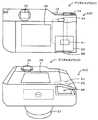
次に、本発明の実施の形態を図面に基づいて説明する。図1は本発明の一実施形態であるデジタルカメラ20の構成の概略を示す構成図、図2はデジタルカメラ20の下面からの斜視図である。本実施形態のデジタルカメラ20は、図1に示すように、被写体からの光を入射するレンズユニット21と、画像を表示する表示部25と、ユーザーからの入力を受け付ける操作部30と、メモリーカードMCとのデータのやりとりを行うメモリーカードコントローラー36と、装置全体を制御するメインコントローラー40と、画像撮影を実行する撮影部50と、撮影に関する指示位置を操作者の指を撮像して取得する指示取得ユニット60とを備えている。 Next, embodiments of the present invention will be described with reference to the drawings. FIG. 1 is a block diagram showing an outline of the configuration of a
レンズユニット21は、レンズマウントを介して装着及び取外し可能にデジタルカメラ20の筐体11に取り付けられている。このレンズユニット21は、凸レンズと凹レンズとを組み合わせて構成され、その一部がレンズ筒の内部を軸方向に移動可能に構成されたレンズ群22と、光量を調節する絞り機構23と、図示しないモーターの駆動によりレンズ群22を移動させるレンズ駆動部24とを備えている。このレンズユニット21は、レンズ駆動部24により一部のレンズを移動させて自動ズームや自動フォーカスを行う形式のユニットとして構成されている。レンズ駆動部24は、撮影部50のレンズ制御部53と電気的に接続されており、レンズ制御部53からの信号に応じてレンズを移動させる。 The
表示部25は、撮影部50のファインダー部54のイメージセンサーで得られたファインダー画像を表示するEVF(Electronic View Finder)26と、各種設定画面や、レンズユニット21から得られる撮影画像を表示するモニター28とを備えている。 The
操作部30は、デジタルカメラ20を起動、終了する際に押下される電源キー32や、ユーザーの操作によって押下されるとレンズユニット21を通じてイメージセンサー51上に結像した画像を取り込むタイミングをメインコントローラー40へ出力するシャッターキー34などを含む。シャッターキー34は、ユーザーの操作によって半押しや全押しが可能であり、半押し状態では半押し信号をメインコントローラー40へ出力し、半押し状態後に全押しすることにより全押し信号をメインコントローラー40へ出力する。なお、図示しないが、操作部30には、撮影モードを設定可能なダイヤルスイッチ、シャッタスピードを設定するボタン、ホワイトバランスを設定するためのボタンなど撮影に必要な一連の設定を行うためのボタンが配設されている。 The
メモリーカードコントローラー36は、メモリーカードMCに記憶された画像データを読み出したり、撮影部50で生成された画像データをメモリーカードMCに書き込んだりする処理などを実行する。 The
メインコントローラー40は、CPU42を中心とするマイクロプロセッサとして構成されており、処理プログラムや各種テーブルを記憶するフラッシュメモリー43と、データを一時的に記憶するRAM44と、外部機器とのデータのやりとりを行うインターフェイス(I/F)45と、表示画面を作成して表示部25に表示出力する表示制御部46とを備えている。メインコントローラー40には、操作部30からの各種の入力信号や、メモリーカードMCから読み出した各種データ、撮影部50からの各種信号、指示取得ユニット60からの信号などが入力される。また、メインコントローラー40からは、メモリーカードMCへ書き込む各種データ、表示部25への信号などが出力される。 The
撮影部50は、レンズユニット21を通った光により撮影を行うイメージセンサー51や、電気信号から画像データを生成する画像生成部52、レンズユニット21を制御するレンズ制御部53、ファインダー画像を生成するファインダー部54、画像撮影に用いられる構造などを含む撮像機構55などを備えている。イメージセンサー51は、光を光電変換によって電気信号に変換するセンサーである。このイメージセンサー51は、マトリックス状に配置された複数のフォトダイオードと、各フォトダイオードに形成されフォトダイオードから受け取った電荷を転送するCCDとを備えている。なお、イメージセンサーとしては、CMOS型のイメージセンサーを採用してもよい。画像生成部52は、イメージセンサー51から出力された電気信号をデジタル信号に変換するアナログフロントエンド(AFE)や、ホワイトバランス処理やシャープネス処理やガンマ補正処理などを行いデジタル信号から画像データを生成する処理実行部などを備えている。ファインダー部54は、ファインダー用イメージセンサーを備え、ファインダー用の画像を生成する。撮像機構55は、例えば、レンズユニット21とイメージセンサー51との間に配置されたシャッター57などを含んでいる。 The
指示取得ユニット60は、図1,2に示すように、デジタルカメラ20のレンズと反対側の面から筐体11を見たときの左側面側の下方の領域に配設されている。筐体11には、図2に示すように、左側面の下面に操作者の指が挿入可能な挿入口68が設けられており、この挿入口68から挿入可能な内部空間に指示取得ユニット60が配設されている。この指示取得ユニット60は、挿入口68から挿入された操作者の指を撮像する撮像素子61と、撮影部50によって撮影される画像範囲に対応する所定領域としてのタッチパネル62と、撮像素子61で撮像した画像を処理して表示制御部46へ出力する画像処理出力部63とを備えている。この指示取得ユニット60は、操作者の指が非接触な状態で、タッチパネル62と操作者の指の位置との間の相対位置の情報を、タッチパネル62上に位置する指を撮像することにより取得するユニットとして構成されている。撮像素子61は、光を光電変換によって電気信号に変換して画像処理出力部63へ出力するよう構成されている。タッチパネル62は、撮像部50の撮影領域に対応する形状に形成されている。即ち、タッチパネル62は、イメージセンサー51で取得する画像の中央(EVF26の画像の中央)が、タッチパネル62の中央に対応し、イメージセンサー51で取得する画像の左上部(EVF26の画像の左上部)が、タッチパネル62の左上部に対応するなどのように、構成されている。このタッチパネル62は、所定領域上での操作者の指が接触した接触位置の情報(接触位置座標)を取得し、取得した接触座標を画像処理出力部63へ出力するよう構成されている。画像処理出力部63は、撮像素子61により撮像されたタッチパネル62上の画像のうち指先を画像認識し、その他の領域をトリミングしてこの指先の画像を指示位置画像として生成する処理を行う。なお、指先の認識は、例えば、画像内のエッジを検出し、予め記憶した指先形状、大きさ、色などに合う領域をこのエッジ画像を用いて抽出することにより行うことができる。また、画像処理出力部63は、指先の相対位置情報(相対位置座標)やタッチパネル62からの接触位置座標などをメインコントローラー40へ出力する処理を行う。デジタルカメラ20では、この指示取得ユニット60の機能によって、タッチパネル62上に非接触状態の指があると、その指の画像がEVF26のファインダー画面の対応する位置に表示され、タッチパネル62を触ると、その接触位置に応じたファインダー画面の位置にオートフォーカスエリアが設定されるよう構成されている。 As shown in FIGS. 1 and 2, the
次に、こうして構成された本実施形態のデジタルカメラ20の動作について説明する。図3は、メインコントローラー40により実行される撮影処理ルーチンの一例を示すフローチャートである。このルーチンは、電源キー32がオンにされ、撮影モードが起動したあと実行される。このルーチンでは、メインコントローラー40がレンズユニット21や、表示部25、メモリーカードコントローラー36、撮影部50、指示取得ユニット60などを利用しながら実行するものとした。このルーチンが開始されると、指示取得ユニット60がタッチパネル62上を撮像し(ステップS100)、撮像した画像の指先部分を画像認識処理により認識し、この指先画像から指示位置画像を作成し、指の位置を認識する(ステップS110)。なお、指先が認識されない場合は、指示位置画像の生成を行わないものとしてもよい。この指の位置は、撮像した画像全体の中で指先画像の所定位置(例えば、中心)が位置する2次元座標(X座標とY座標)として取得する。次に、指示位置画像や指の位置を取得したCPU42は、EVF26に表示するファインダー画面を作成し、表示制御部46によりファインダー画面をEVF26に表示出力させる(ステップS120)。ファインダー画面は、ファインダー部54から取得したファインダー画像において、指示位置座標に応じた位置に指示位置画像を半透過させた画像をオーバーレイして作成するものとした(後述図4参照)。またこのとき、モニター28にはファインダー部54から取得したファインダー画像を表示するが指示位置画像の表示は行わない。 Next, the operation of the
次に、指示取得ユニット60がタッチパネル62に操作者の指が接触したか否かを判定する(ステップS130)。タッチパネル62に操作者の指が接触していないときには、CPU42は、シャッターキー34が押下されたか否かに基づいて、本撮影が行われたか否かを判定し(ステップS160)、本撮影が行われていないときには、ステップS100以降の処理を実行する。即ち、タッチパネル62上での操作者の指の指示位置座標及び指の画像を取得し、指示位置座標に応じた位置に指示位置画像を配置したファインダー画面をEVF26に表示する。これにより、操作者は、タッチパネル62に接触する前に、どのあたりをフォーカスエリアとするかを確認することができる。 Next, the
一方、ステップS130でタッチパネル62に操作者の指が接触したときには、タッチパネル62上の接触位置に応じたファインダー画面の位置をフォーカスエリアに設定する(ステップS140)。続いて、そのフォーカスエリアにフォーカスを合わせるフォーカス制御中であることを示す所定の合焦画像73を表示すると共に、そのフォーカスエリアにフォーカスが合うように、レンズ制御部53がレンズ駆動部24を駆動するフォーカス制御を実行する(ステップS150)。ここでは、合焦画像73を表示して表示態様を変えることにより、フォーカス位置が固定されたことを視認可能とするのである。このように、操作者は、ファインダー画面上で動く指示位置画像を確認しながら、タッチパネル62上でフォーカスを合わせたいところに非接触で指を動かし、タッチパネル62を触ることでその位置にフォーカスさせることができる。 On the other hand, when the operator's finger touches the
続いて、ステップS160でシャッターキー34が押下され、本撮影が行われたときには、CPU42は、撮影処理を実行する(ステップS170)。この撮影処理では、指示位置でオートフォーカスした状態で、且つ、予め設定された絞り値になるよう絞り機構23を調整した状態で、シャッター57を切り、イメージセンサー51で光を光電変換によって電気信号に変換し、この電気信号に基づいて画像生成部52で画像データを生成する処理を行い、生成した画像データをRAM44やメモリーカードコントローラー36を介してメモリーカードMCに記憶する処理を実行する。そして、CPU42は、電源キー32がオフされたか否かと、モード変更キーを操作されてモードの変更が指示されたかどうかに基づいて撮影終了したか否かを判定し(ステップS180)、撮影終了していないときには、ステップS100以降の処理を繰り返し実行する。一方、撮影終了したときには、このルーチンを終了する。 Subsequently, when the
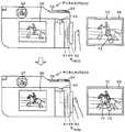
ここで、この撮影処理ルーチンでの動きの具体例を説明する。図4は、撮影操作とファインダー画面の一例の説明図である。図4の上段に示すように、操作者は、EVF26を見ながら、挿入口68に指を挿入してタッチパネル62上でこの指を移動させる。すると、指示取得ユニット60は、撮像素子61により撮像された指の画像及び座標位置を取得し、これを受けたメインコントローラー40は、タッチパネル62の指示位置座標に対応するEVF26の座標位置に指示位置画像72を配置したファインダー画面70を作成してEVF26に表示させる。次に、図4の中段に示すように、操作者は、フォーカスを望む位置に指示位置画像72が移動すると、その位置でタッチパネル62を触る。すると、指示取得ユニット60は、タッチパネル62での接触位置座標を出力し、これを受けたメインコントローラー40は、その接触位置に対応する位置に合焦画像73をオーバーレイすると共に、接触位置に対応する位置に対してフォーカス処理を実行させる。ここでは、合焦画像73は、半透過した円形画像とした。そして、図4下段に示すように、操作者がシャッターキー34を押下して撮影する。すると、メインコントローラー40は、操作者が指定しているフォーカス位置にフォーカスした状態で、撮影処理を実行し、画像データ80を作成、保存するのである。このように、操作者は、まるでカーソルを移動させてクリックするような、直感的な操作により、瞬時にフォーカスエリアを指定し、撮影を行うことができるのである。 Here, a specific example of the movement in the photographing processing routine will be described. FIG. 4 is an explanatory diagram of an example of a shooting operation and a viewfinder screen. As shown in the upper part of FIG. 4, the operator inserts a finger into the
ここで、本実施形態の構成要素と本発明の構成要素との対応関係を明らかにする。本実施形態の撮影部50が本発明の撮影部に相当し、EVF26がファインダーに相当し、タッチパネル62が所定領域に相当し、指示取得ユニット60が位置取得部に相当し、表示制御部46が表示制御部に相当し、オートフォーカス(合焦処理)が撮影関連処理に相当する。なお、本実施形態では、デジタルカメラ20の動作を説明することにより本発明の撮影装置の制御方法の一例も明らかにしている。 Here, the correspondence between the components of the present embodiment and the components of the present invention will be clarified. The
以上詳述した本実施形態のデジタルカメラ20によれば、筐体11に設けられ撮影部50によって撮影される画像範囲に対応するタッチパネル62(所定領域)に操作者の指が非接触な状態で、このタッチパネル62と操作者の指の位置との間の相対位置座標を取得し、取得した指の相対位置座標に基づいてEVF26(ファインダー)に指示位置画像72を表示させる。したがって、ファンダーを覗いた状態でも指示位置をより確認しやすい。また、タッチパネル62に指が接触すると、この接触位置座標に基づいてオートフォーカス処理を実行するため、指示位置を確認しやすい状態から続けてオートフォーカス処理を実行させることができる。更に、オートフォーカス処理は、撮影される画像上の位置に応じて処理を行うため、本発明を適用する意義が高い。更にまた、操作者の指がタッチパネル62に接触しているか否かに応じて、異なる指示位置画像を表示するため、指示位置の確認に加えて、オートフォーカスが固定している状態をも確認することができる。そして、操作者の指を撮影することにより相対位置座標を取得するため、比較的容易に、かつ比較的簡素な構成により、非接触状態での指の位置を取得することができる。そしてまた、撮影した操作者の指の画像を用いた指示位置画像を表示させるため、自身の指を見るという、より直感的な状態で指示位置を確認することができる。 According to the
また、操作者の指がタッチパネル62に非接触状態でフォーカスしたい位置を選択し、タッチパネル62に触れることで、レンズ制御部53によるオートフォーカスが駆動するため、例えば、タッチ位置がずれて何回にもわたるタッチ操作を行い何回もフォーカス処理するなどという、無駄な処理の発生をより抑制させることができる。更に、何回にもわたりオートフォーカス動作を繰り返すことによって生じるタイムラグの発生を抑制可能であるため、シャッターチャンスをより逃しにくいという効果も生じる。更にまた、EVF26へファインダー画像と共に指示位置画像72を表示するため、ファインダーを覗いたままオートフォーカス位置を設定可能であり、撮影に集中することができる。 In addition, since the operator's finger selects a position to focus on the
なお、本発明は上述した実施形態に何ら限定されることはなく、本発明の技術的範囲に属する限り種々の態様で実施し得ることはいうまでもない。 It should be noted that the present invention is not limited to the above-described embodiment, and it goes without saying that the present invention can be implemented in various modes as long as it belongs to the technical scope of the present invention.
例えば、上述した実施形態では、左側の側面側に設けられた挿入口68に左手の指を挿入して操作する指示取得ユニット60として説明したが、非接触状態の指の位置を取得し、接触した位置にフォーカスエリアを設定するものとすれば、種々の態様を採用することができる。図5は、デジタルカメラ20Bの説明図であり、図6はデジタルカメラ20Cの説明図であり、図7はデジタルカメラ20Dの説明図であり、図8はデジタルカメラ20Eの説明図である。例えば、図5に示すように、筐体11の外部側面にタッチパネル62を配設し、支持部材64により指示された撮像素子61でタッチパネル62上の操作者の指を撮影する指示取得ユニット60Bを備えたデジタルカメラ20Bとしてもよい。こうしても、非接触状態での指の位置に基づいて、指示位置を取得可能であり、EVF26に指示位置画像72を表示可能であるから、上述した実施形態のデジタルカメラ20と同様に、ファンダーを覗いた状態でも指示位置をより確認しやすい。なお、支持部材64は、使用しないときには筐体11に格納可能に構成してもよい。 For example, in the above-described embodiment, the
また、図6に示すように、筐体11の右側の背面側に近い位置の下面に挿入口68Cを設け、右手の親指でタッチパネル62上の操作を行う指示取得ユニット60Cを備えたデジタルカメラ20Cとしてもよい。こうしても、ファンダーを覗いた状態でも指示位置をより確認しやすい。なお、筐体11内部に指を挿入する態様の指示取得ユニット60では、ライトで指を照らして撮像してもよいし、採光窓を設けるものとしてもよい。 In addition, as shown in FIG. 6, a
また、タッチパネル62は、操作者が操作可能であれば、筐体11の上面、下面、左面、右面、背面、前面、更に筐体11の内部空間など、どの位置に設けられていてもよい。また、撮像素子61は、タッチパネル上の指の動きを撮影可能であれば、どのような数でどのように配置されていてもよい。例えば、図7に示すように、透明又は半透明のタッチパネル62を備え、タッチパネル62の配設された筐体11の内部側に撮像素子61を配置し、レンズ65及びタッチパネル62を介して、外部で移動する操作者の指を撮影するよう構成された指示取得ユニット60Dを備えたデジタルカメラ20Dとしてもよい。この指示取得ユニット60Dでは、撮像素子61のピント面はタッチパネル62面となるようレンズ65により調整されている。こうすれば、比較的凹凸の少ない構造の指示取得ユニットとすることができ、更に、ファンダーを覗いた状態でも指示位置をより確認しやすい。また、撮像素子61を1つではなく、2つ以上設けてもよく、複数の撮像素子61を用いて立体的な撮影を行い、指示位置画像の位置を3次元座標(X座標、Y座標、Z座標)として取得するようにしてもよい。また、指の位置は、どのような座標系で取得してもよく、タッチパネル62の表面方向の2次元座標系であっても、それにタッチパネルの表面に垂直な方向を加えた3次元座標系であってもよく、指示位置画像の位置を1次元ずつスイッチ操作で切り換えながら決定する場合等では、1次元座標系であってもよい。また、直交座標系に限られず斜交座標系や曲座標系で表してもよい。座標系の限定も任意に定めることができる。 Further, the
上述した実施形態では、所定領域をタッチパネル62とし、タッチパネル62を触った位置にフォーカスエリアを設定するものとしたが、所定領域はタッチパネルでなくてもよい。例えば、他の決定ボタンなどを用い、この決定ボタンの押下により現在の指の位置をフォーカスエリアに決定するものとしてもよい。こうしても、ファンダーを覗いた状態でも指示位置をより確認しやすい。 In the above-described embodiment, the predetermined area is the
上述した実施形態では、操作者の指がタッチパネル62に接触しているか否かに応じて、合焦画像73を用いて異なる指示位置画像を表示させるものとしたが、特にこれに限定されない。指示位置画像72の異なる態様としては、例えば、指示位置画像72の色を変更したり、画像の形状を変更したり、指示位置画像72自体を全く異なるものと入れ替えたりしてもよい。あるいは、操作者の指がタッチパネル62に接触しているか否かに応じて、異なる指示位置画像を表示させるものとしたが、表示態様を変化させないものとしてもかまわない。こうしても、ファンダーを覗いた状態でも指示位置を確認することはできる。 In the above-described embodiment, different designated position images are displayed using the
上述した実施形態では、指示位置画像72を撮影した指を用いて作成するものとしたが、特にこれに限定されない。例えば、指をトリミングして指画像としたが、トリミングしない操作者の手の画像としてもよいし、指以外の所定の画像としてよい(後述図8参照)。また、指を半透過した指示位置画像72を表示するものとしたが、指の距離が遠いほど透過度を高めるなどし、距離感がつかめるようにしてもよい。こうすれば、タッチパネル62への指の誤接触などを抑制することができる。また、合焦画像73は指がタッチパネル62に触れたときにすぐさま表示するようにしてもよいし、ファーカスが合ってから表示するなど指がタッチパネル62に触れてから時間が経過してから表示するようにしてもよい。 In the above-described embodiment, the designated
上述した実施形態では、タッチパネル62上の指を撮影することにより指示位置に関する情報を取得するものとしたが、指示位置が把握可能であれば、撮影に限られない。例えば、図8に示すように、所定領域としてのタッチパネル62上での静電容量を検出する静電容量センサー66を備え、非接触状態での指の位置をこの静電容量センサー66により取得する指示取得ユニット60Eを備えたデジタルカメラ20Eとしてもよい。こうしても、静電容量センサーを用いて、比較的容易に、非接触状態の指の位置を検出することができる。なお、この指示取得ユニット60Eでは、ファインダー画面70上に指以外の画像である指示位置画像72Eを表示したファインダー画面70をEVF26に表示する。ここでは、指示位置画像72Eを半透過した円形画像とし、指がタッチパネル62に接触したときの合焦画像73Eは円の中心に×を加えたものとした。あるいは、静電容量センサー66を熱容量センサーとし、熱量や温度に基づいて、操作者の指の位置を検出するものとしてもよい。こうしても、比較的容易に非接触状態での指の位置を取得することができる。 In the above-described embodiment, the information on the designated position is acquired by photographing a finger on the
上述した実施形態では、ファインダー部54で撮影したファインダー画像を加工してEVF26に表示するものとしたが、特にこれに限定されず、例えば、レンズユニット21を介してイメージセンサー51で撮影した画像をファインダー画像としてEVF26に表示するものとしてもよい。こうすれば、実際のフォーカスが反映された画像をEVF26に表示することができ、操作者は、撮影画像を想像しやすい。なお、上述した実施形態では説明しなかったが、ファインダー部54で撮影したファインダー画像を加工してEVF26に表示するに際して、フォーカスエリアを反映させ、フォーカスエリア以外をぼかすよう画像加工したフォーカス画像を用いてファインダー画面70を作成してもよい。 In the above-described embodiment, the finder image captured by the
上述した実施形態では、ファインダーを電子画像を表示するEVF26としたが、特にこれに限定されず、指示位置画像を重ね合わせるものとすれば、一眼レフのように、外部からの光によるファインダー画像を写すものとしてもよい。 In the above-described embodiment, the
上述した実施形態では、撮像素子61、タッチパネル62などは指示取得ユニット60とし、撮影部50のファインダー部54、メインコントローラー40のCPU42や表示制御部46など、本発明の構成の一部を各ユニットに備える形式で説明したが、特にこれに限定されず、撮像素子61やタッチパネル62は撮影部50にあってもよいし、表示制御部46が撮影部50にあってもよい。本発明の撮影部、ファインダー、所定領域、位置取得部及び表示制御部をデジタルカメラ20が備えるものとすれば、これらは、どのユニットに設けられているものとしてもよい。また、撮像素子61で取得した電気信号を画像生成部52を利用して画像生成するものとしてもよい。また、モニター28もタッチパネルであるとしてもよい。そうすれば、EVF26ではなくモニター28をみて撮影を行おうとしているユーザーは、タッチパネル62の代わりにモニター28を指で触ることでフォーカスエリアを指定することができる。この場合、EVF26を除いているユーザーは意図せずモニター28に触れてしまうおそれがあることから、ユーザーがEVFを覗いている場合には、モニター28での操作を受け付けず、ユーザーがモニター28を見ている場合には、モニター28での操作を受けるようにすることが望ましい。 In the above-described embodiment, the
上述した実施形態では、撮影関連処理として、合焦処理を行うものとしたが、ファインダー画面上で位置を指示するものであれば特にこれに限定されず、例えば、測距処理や、測光処理などに応用してもよい。測距処理、測光処理についても、撮影される画像上の位置に応じて処理を行うため、本発明を適用する意義が高い。 In the above-described embodiment, the focusing process is performed as the shooting-related process. However, the present invention is not particularly limited as long as the position is instructed on the finder screen. For example, the distance measurement process, the photometry process, or the like. You may apply to. Since the distance measurement process and the photometry process are also performed in accordance with the position on the image to be captured, it is highly significant to apply the present invention.
上述した実施形態では、本発明をデジタルカメラ20に適用して説明したが、デジタルビデオカメラに適用してもよいし、デジタルカメラの制御方法としてもよいし、このプログラムとしてもよい。また、上述した実施形態や変形例を適宜組み合わせたものとしてもよい。 In the above-described embodiments, the present invention has been applied to the
11 筐体、20,20B〜20E デジタルカメラ、21 レンズユニット、22 レンズ群、23 絞り機構、24 レンズ駆動部、25 表示部、26 EVF、28 モニター、30 操作部、32 電源キー、34 シャッターキー、36 メモリーカードコントローラー、40 メインコントローラー、42 CPU、43 フラッシュメモリー、44 RAM、45 I/F、46 表示制御部、50 撮影部、51 イメージセンサー、52 画像生成部、53 レンズ制御部、54 ファインダー部、55 撮像機構、57 シャッター、60,60B〜60E 指示取得ユニット、61 撮像素子、62 タッチパネル、63 画像処理出力部、64 支持部材、65 レンズ、66 静電容量センサー、68 挿入口、70 ファインダー画面、72,72E 指示位置画像、73,73E 合焦画像、80 画像データ、MC メモリーカード。DESCRIPTION OF
Claims (9)
Translated fromJapanese前記撮影部によって撮影される画像を表示するファインダーと、
筐体に設けられ所定領域に操作者の指が非接触な状態で、該所定領域と前記操作者の指の位置との間の相対位置の情報を取得する位置取得部と、
前記相対位置の情報に基づいて前記ファインダーに指示位置画像を表示させる表示制御部と、
を備える撮影装置。A shooting unit that takes a picture with light passing through the lens;
A finder for displaying an image photographed by the photographing unit;
A position acquisition unit that is provided in the housing and acquires information on a relative position between the predetermined area and the position of the operator's finger in a state where the operator's finger is not in contact with the predetermined area;
A display control unit for displaying an instruction position image on the finder based on the information on the relative position;
An imaging device comprising:
前記撮影部は、前記位置取得部が前記接触位置の情報を取得すると該接触位置の情報に基づいて前記撮影に関する撮影関連処理を実行する、請求項1に記載の撮影装置。The position acquisition unit also acquires information on a contact position where the operator's finger contacts the predetermined area,
The imaging device according to claim 1, wherein when the position acquisition unit acquires the information on the contact position, the imaging unit executes an imaging-related process related to the imaging based on the information on the contact position.
(a)筐体に設けられ所定領域に操作者の指が非接触な状態で、該所定領域と前記操作者の指の位置との間の相対位置の情報を取得するステップと、
(b)前記相対位置の情報に基づいて前記ファインダーに指示位置画像を表示させるステップと、
を含む撮影装置の制御方法。An imaging device control method comprising: an imaging unit that performs imaging using light that passes through a lens; and a finder that displays an image captured by the imaging unit,
(A) obtaining information on a relative position between the predetermined area and the position of the operator's finger in a state where the operator's finger is not in contact with the predetermined area provided on the housing;
(B) displaying an indicated position image on the finder based on the information on the relative position;
A method for controlling an imaging apparatus including:
Priority Applications (1)
| Application Number | Priority Date | Filing Date | Title |
|---|---|---|---|
| JP2011055428AJP2012191570A (en) | 2011-03-14 | 2011-03-14 | Photographing device, control method of the same and program |
Applications Claiming Priority (1)
| Application Number | Priority Date | Filing Date | Title |
|---|---|---|---|
| JP2011055428AJP2012191570A (en) | 2011-03-14 | 2011-03-14 | Photographing device, control method of the same and program |
Publications (1)
| Publication Number | Publication Date |
|---|---|
| JP2012191570Atrue JP2012191570A (en) | 2012-10-04 |
Family
ID=47084222
Family Applications (1)
| Application Number | Title | Priority Date | Filing Date |
|---|---|---|---|
| JP2011055428AWithdrawnJP2012191570A (en) | 2011-03-14 | 2011-03-14 | Photographing device, control method of the same and program |
Country Status (1)
| Country | Link |
|---|---|
| JP (1) | JP2012191570A (en) |
Cited By (4)
| Publication number | Priority date | Publication date | Assignee | Title |
|---|---|---|---|---|
| KR20150035188A (en)* | 2013-09-27 | 2015-04-06 | 엘지전자 주식회사 | Mobile terminal and operation method thereof |
| US9967468B2 (en) | 2014-09-05 | 2018-05-08 | Samsung Electronics Co., Ltd. | Photographing apparatus and photographing method |
| JP2020039135A (en)* | 2016-01-28 | 2020-03-12 | マクセル株式会社 | Imaging device |
| CN112352418A (en)* | 2018-06-27 | 2021-02-09 | 富士胶片株式会社 | Imaging device, imaging method, and program |
- 2011
- 2011-03-14JPJP2011055428Apatent/JP2012191570A/ennot_activeWithdrawn
Cited By (11)
| Publication number | Priority date | Publication date | Assignee | Title |
|---|---|---|---|---|
| KR20150035188A (en)* | 2013-09-27 | 2015-04-06 | 엘지전자 주식회사 | Mobile terminal and operation method thereof |
| KR102039485B1 (en) | 2013-09-27 | 2019-11-01 | 엘지전자 주식회사 | Mobile terminal and operation method thereof |
| US9967468B2 (en) | 2014-09-05 | 2018-05-08 | Samsung Electronics Co., Ltd. | Photographing apparatus and photographing method |
| JP2020039135A (en)* | 2016-01-28 | 2020-03-12 | マクセル株式会社 | Imaging device |
| US11221707B2 (en) | 2016-01-28 | 2022-01-11 | Maxell, Ltd. | Imaging device |
| US11614822B2 (en) | 2016-01-28 | 2023-03-28 | Maxell, Ltd. | Imaging device |
| US12061760B2 (en) | 2016-01-28 | 2024-08-13 | Maxell, Ltd. | Imaging device |
| JP7606546B2 (en) | 2016-01-28 | 2024-12-25 | マクセル株式会社 | Imaging device |
| CN112352418A (en)* | 2018-06-27 | 2021-02-09 | 富士胶片株式会社 | Imaging device, imaging method, and program |
| CN112352418B (en)* | 2018-06-27 | 2023-11-21 | 富士胶片株式会社 | Camera device and camera method |
| US11954290B2 (en) | 2018-06-27 | 2024-04-09 | Fujifilm Corporation | Imaging apparatus, imaging method, and program |
Similar Documents
| Publication | Publication Date | Title |
|---|---|---|
| JP4530067B2 (en) | Imaging apparatus, imaging method, and program | |
| JP6112819B2 (en) | Electronic device, driving method and program | |
| CN101378458B (en) | Use digital photographing apparatus and the method for face recognition function | |
| CN108476284B (en) | camera | |
| JP6083987B2 (en) | Imaging apparatus, control method thereof, and program | |
| CN104813227B (en) | Camera and camera method | |
| US10715719B2 (en) | Image capturing apparatus and control method thereof | |
| JP5709816B2 (en) | IMAGING DEVICE, ITS CONTROL METHOD, CONTROL PROGRAM, AND RECORDING MEDIUM | |
| CN107797714B (en) | Electronic device, control method thereof, and storage medium | |
| JP6302215B2 (en) | Imaging device | |
| US20120105588A1 (en) | Image capture device | |
| JP2017011579A (en) | Imaging device, control method for the same, program and storage medium | |
| JP7446913B2 (en) | Electronic devices, control methods for electronic devices, and programs | |
| JP2012191570A (en) | Photographing device, control method of the same and program | |
| JP2008079193A (en) | Digital camera | |
| CN112997115B (en) | Image pickup apparatus and electronic device having optical input device | |
| JP7466304B2 (en) | Imaging device, control method thereof, program, and storage medium | |
| CN114631307B (en) | Imaging device including an operating member for moving the position of a display object on a screen | |
| JP7383394B2 (en) | Electronic equipment with optical input devices | |
| JP7301631B2 (en) | Imaging device | |
| JP7071197B2 (en) | Imaging device and its control method | |
| JP2017135735A (en) | Electronic device, driving method and program | |
| JP2023083876A (en) | Control device, control method and program | |
| WO2020095815A1 (en) | Imaging apparatus and electronic equipment that have optical input device | |
| JP2021061531A (en) | Imaging control device and control method thereof, program, and storage medium |
Legal Events
| Date | Code | Title | Description |
|---|---|---|---|
| A300 | Application deemed to be withdrawn because no request for examination was validly filed | Free format text:JAPANESE INTERMEDIATE CODE: A300 Effective date:20140603 |