JP2012189004A - Scroll fluid machine - Google Patents
Scroll fluid machineDownload PDFInfo
- Publication number
- JP2012189004A JP2012189004AJP2011053295AJP2011053295AJP2012189004AJP 2012189004 AJP2012189004 AJP 2012189004AJP 2011053295 AJP2011053295 AJP 2011053295AJP 2011053295 AJP2011053295 AJP 2011053295AJP 2012189004 AJP2012189004 AJP 2012189004A
- Authority
- JP
- Japan
- Prior art keywords
- shaft
- sleeve
- scroll
- fluid machine
- housing
- Prior art date
- Legal status (The legal status is an assumption and is not a legal conclusion. Google has not performed a legal analysis and makes no representation as to the accuracy of the status listed.)
- Withdrawn
Links
- 239000012530fluidSubstances0.000titleclaimsabstractdescription52
- 238000005452bendingMethods0.000claimsdescription25
- 230000002093peripheral effectEffects0.000claimsdescription12
- 239000003921oilSubstances0.000description21
- 230000004048modificationEffects0.000description9
- 238000012986modificationMethods0.000description9
- 239000010687lubricating oilSubstances0.000description7
- 230000005540biological transmissionEffects0.000description6
- 238000010586diagramMethods0.000description4
- 230000006835compressionEffects0.000description3
- 238000007906compressionMethods0.000description3
- 238000005057refrigerationMethods0.000description3
- 238000007789sealingMethods0.000description3
- 230000004323axial lengthEffects0.000description2
- 239000003507refrigerantSubstances0.000description2
- 239000000470constituentSubstances0.000description1
- 230000000694effectsEffects0.000description1
- 230000008014freezingEffects0.000description1
- 238000007710freezingMethods0.000description1
- 238000010438heat treatmentMethods0.000description1
- 239000000463materialSubstances0.000description1
- 238000000034methodMethods0.000description1
- 230000002265preventionEffects0.000description1
- 230000003014reinforcing effectEffects0.000description1
- 229910001220stainless steelInorganic materials0.000description1
- 239000010935stainless steelSubstances0.000description1
Images


Landscapes
- Rotary Pumps (AREA)
Abstract
Description
Translated fromJapaneseこの発明は、スクロール流体機械に関し、さらに詳しくは、シャフトの撓みを抑制できるスクロール流体機械に関する。 The present invention relates to a scroll fluid machine, and more particularly to a scroll fluid machine capable of suppressing shaft deflection.
一般的なスクロール圧縮機は、固定スクロールおよび旋回スクロールと、旋回スクロールに動力を伝達するシャフトと、これらを収容するハウジングとを備えている。かかる構成を採用する従来のスクロール圧縮機として、特許文献1に記載される技術が知られている。 A general scroll compressor includes a fixed scroll and a turning scroll, a shaft that transmits power to the turning scroll, and a housing that houses them. As a conventional scroll compressor employing such a configuration, a technique described in Patent Document 1 is known.
ここで、一般的なスクロール流体機械では、その性能を向上させるために、より一層の高速回転化および高負荷化が求められる。また、スクロール流体機械の稼働時には、シャフトの撓みが発生する。このシャフトの撓みは、シャフトが旋回スクロールから受ける荷重に起因して発生し、高速回転時および高負荷時ほど大きくなる。 Here, in a general scroll fluid machine, in order to improve the performance, further higher speed rotation and higher load are required. Further, when the scroll fluid machine is in operation, the shaft is bent. This deflection of the shaft occurs due to the load that the shaft receives from the orbiting scroll, and becomes larger when the shaft rotates at a high speed and when the load is high.
そこで、この発明は、上記に鑑みてなされたものであって、シャフトの撓みを効果的に抑制できるスクロール流体機械を提供することを目的とする。 Therefore, the present invention has been made in view of the above, and an object of the present invention is to provide a scroll fluid machine that can effectively suppress the deflection of the shaft.
上記目的を達成するため、この発明にかかるスクロール流体機械は、固定スクロールおよび旋回スクロールと、前記旋回スクロールに動力を伝達するシャフトと、前記固定スクロール、前記旋回スクロールおよび前記シャフトを収容するハウジングとを備えるスクロール流体機械であって、前記ハウジングに設置されて前記シャフトを回転可能に支持するメイン軸受およびサブ軸受と、前記メイン軸受および前記サブ軸受の間に配置されて前記ハウジングと前記シャフトとの隙間を封止するリップシールと、前記メイン軸受および前記リップシールの間に配置されると共に前記シャフトに嵌め込まれて前記シャフトの剛性を補強するスリーブとを備えることを特徴とする。 In order to achieve the above object, a scroll fluid machine according to the present invention includes a fixed scroll and a orbiting scroll, a shaft for transmitting power to the orbiting scroll, and a housing for housing the fixed scroll, the orbiting scroll and the shaft. A scroll fluid machine comprising: a main bearing and a sub bearing that are installed in the housing and rotatably support the shaft; and a gap between the housing and the shaft that is disposed between the main bearing and the sub bearing. And a sleeve that is disposed between the main bearing and the lip seal and is fitted into the shaft to reinforce the rigidity of the shaft.
また、この発明にかかるスクロール流体機械では、前記スリーブが、前記シャフトの撓み方向に拡幅した幅広形状を有することが好ましい。 In the scroll fluid machine according to the present invention, it is preferable that the sleeve has a wide shape widened in a bending direction of the shaft.
また、この発明にかかるスクロール流体機械では、前記スリーブが、前記シャフトの撓み方向に対して反対方向に偏心した偏心構造を有することが好ましい。 In the scroll fluid machine according to the present invention, it is preferable that the sleeve has an eccentric structure that is eccentric in a direction opposite to a bending direction of the shaft.
また、この発明にかかるスクロール流体機械では、前記スリーブが、前記ハウジングの内壁面に沿った外周形状を有することが好ましい。 In the scroll fluid machine according to the present invention, it is preferable that the sleeve has an outer peripheral shape along an inner wall surface of the housing.
また、この発明にかかるスクロール流体機械では、前記スリーブが、前記メイン軸受側から前記リップシール側に抜ける油溝を有することが好ましい。 In the scroll fluid machine according to the present invention, it is preferable that the sleeve has an oil groove that extends from the main bearing side to the lip seal side.
この発明にかかるスクロール流体機械では、スリーブがシャフトの剛性を補強するので、高速回転時および高負荷化時におけるシャフトの撓みが抑制される。これにより、製品の信頼性が向上する利点がある。 In the scroll fluid machine according to the present invention, since the sleeve reinforces the rigidity of the shaft, bending of the shaft during high-speed rotation and high load is suppressed. This has the advantage that the reliability of the product is improved.
以下、この発明につき図面を参照しつつ詳細に説明する。なお、この実施の形態によりこの発明が限定されるものではない。また、この実施の形態の構成要素には、発明の同一性を維持しつつ置換可能かつ置換自明なものが含まれる。また、この実施の形態に記載された複数の変形例は、当業者自明の範囲内にて任意に組み合わせが可能である。 Hereinafter, the present invention will be described in detail with reference to the drawings. Note that the present invention is not limited to the embodiments. Further, the constituent elements of this embodiment include those that can be replaced while maintaining the identity of the invention and that are obvious for replacement. In addition, a plurality of modifications described in this embodiment can be arbitrarily combined within a range obvious to those skilled in the art.
[スクロール流体機械]
図1は、この発明の実施の形態にかかるスクロール流体機械を示す構成図である。同図は、スクロール流体機械の軸方向断面図を示している。[Scroll fluid machinery]
FIG. 1 is a configuration diagram showing a scroll fluid machine according to an embodiment of the present invention. This figure shows an axial sectional view of the scroll fluid machine.
このスクロール流体機械1は、例えば、トラックなどの陸上輸送機器に搭載される冷凍装置に適用される。一般的な冷凍装置は、室外に配置される室外ユニットと、室内に配置される室内ユニットとを備え、室外ユニットおよび室内ユニットの間に作動流体(冷媒ガス)を循環させて室内および室外にて熱交換することにより、室内の加温運転および冷凍運転を行い得る。かかる冷凍装置において、スクロール流体機械1は、圧縮機として用いられ、作動流体を圧縮して室外ユニットおよび室内ユニットの各構成要素に供給する。 The scroll fluid machine 1 is applied to, for example, a refrigeration apparatus mounted on land transportation equipment such as a truck. A general refrigeration apparatus includes an outdoor unit disposed outside and an indoor unit disposed indoors, and a working fluid (refrigerant gas) is circulated between the outdoor unit and the indoor unit so as to be indoors and outdoors. By performing heat exchange, indoor heating operation and freezing operation can be performed. In such a refrigeration apparatus, the scroll fluid machine 1 is used as a compressor, compresses the working fluid, and supplies it to each component of the outdoor unit and the indoor unit.
なお、この実施の形態では、スクロール流体機械1の一例としてスクロール圧縮機について説明するが、スクロール膨張機にも同様の構成を適用できる。 In this embodiment, a scroll compressor is described as an example of the scroll fluid machine 1, but the same configuration can be applied to a scroll expander.
スクロール流体機械1は、ハウジング2と、固定スクロール3および旋回スクロール4と、動力伝達機構5と、駆動機構6と、軸封構造7とを備える(図1参照)。 The scroll fluid machine 1 includes a housing 2, a fixed scroll 3, a turning scroll 4, a
ハウジング2は、筒状のフロントケース21と蓋状のリアケース22とをボルト結合して構成される。このハウジング2は、その軸方向を水平方向に向けて横置き状態で配置される。また、ハウジング2は、作動流体の吸入口23および吸入室25をフロントケース21側に有し、吐出口24および吐出室26をリアケース22側に有する。このハウジング2には、固定スクロール3および旋回スクロール4と、動力伝達機構5とが収容される。 The housing 2 is configured by bolting a cylindrical
固定スクロール3は、端板31と、この端板31に形成された渦巻き状のラップ32とを有する。この固定スクロール3は、端板31の背面をリアケース22にボルト結合してハウジング2に固定され、また、ラップ32をフロントケース21側に向けて配置される。また、固定スクロール3の端板31により、ハウジング2の吸入室25と吐出室26とが区画される。 The fixed scroll 3 includes an end plate 31 and a
旋回スクロール4は、端板41と、この端板41に形成された渦巻き状のラップ42とを有する。この旋回スクロール4は、ラップ42を固定スクロール3のラップ32に対向させて配置される。このとき、旋回スクロール4のラップ42と固定スクロール3のラップ32とが偏心しつつ噛み合うことにより、固定スクロール3と旋回スクロール4との間に複数の圧縮室Sが形成される。 The orbiting scroll 4 has an
動力伝達機構5は、駆動機構6からの動力を旋回スクロール4に伝達して、旋回スクロール4を公転旋回運動させる機構である。この動力伝達機構5は、シャフト51と、メイン軸受52およびサブ軸受53と、ドライブピン54と、ドライブブッシュ55と、ドライブ軸受56と、バランスウェイト57と、自転防止ピン58とを有する。シャフト51は、その回転軸を旋回スクロール4の端板41の背面に垂直に立てて配置される。メイン軸受52およびサブ軸受53は、ハウジング2のフロントケース21側に固定されて、シャフト51を回転可能に支持する。ドライブピン54は、シャフト51の回転軸に対して偏心するピンであり、シャフト51の旋回スクロール4側の端部に取り付けられる。ドライブブッシュ55は、いわゆる滑り子であり、ドライブピン54の外周に嵌め合わされて設置される。ドライブ軸受56は、ドライブピン54およびドライブブッシュ55を回転可能に支持する軸受であり、旋回スクロール4の端板41の背面に形成される。バランスウェイト57は、旋回スクロール4の公転旋回運動によるアンバランスを補正する部材であり、ドライブブッシュ55に一体化される。自転防止ピン58は、旋回スクロール4の自転を防止するピンであり、旋回スクロール4の端板41の背面とハウジング2のフロントケース21との間に介在する。 The
駆動機構6は、動力伝達機構5を介して旋回スクロール4を駆動する機構である。この駆動機構6は、ハウジング2の外部に配置され、回転板61を介してシャフト51に連結される。また、駆動機構6は、駆動ベルトを介して駆動源(例えば、車両のエンジン)に連結される(図示省略)。 The drive mechanism 6 is a mechanism that drives the orbiting scroll 4 via the
軸封構造7は、シャフト51とハウジング2の内壁との隙間を封止する構造であり、リップシール71を有する。リップシール71は、メイン軸受52とサブ軸受53との間に配置される。また、リップシール71は、ハウジング2のフロントケース21の内壁に取り付けられて、シャフト51の周面に付勢する。このリップシール71により、シャフト51とハウジング2の内壁との隙間が封止される。 The
このスクロール流体機械1では、作動流体が、ハウジング2の外部から吸入口23を介して吸入室25に供給される。また、駆動機構6が駆動されると、シャフト51が回転してドライブピン54が偏心回転する。すると、旋回スクロール4が駆動されて固定スクロール3に対して公転旋回運動する。すると、吸入室25の作動流体が固定スクロール3と旋回スクロール4との間の圧縮室Sに取り込まれ、この作動流体が圧縮されて吐出室26に供給される。そして、この吐出室26の作動流体が吐出口24からハウジング2の外部に供給される。 In the scroll fluid machine 1, the working fluid is supplied from the outside of the housing 2 to the
[シャフトのスリーブ]
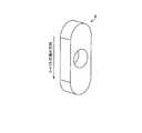
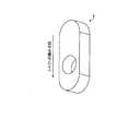
図2は、図1に記載したスクロール流体機械のスリーブを示す説明図である。図3は、図2に記載したスリーブを示す斜視図である。図4は、図2に記載したスリーブの変形例を示す斜視図である。これらの図において、図2は、スリーブをシャフトに取り付けた状態を示し、図3および図4は、スリーブの単体を示している。[Shaft sleeve]
FIG. 2 is an explanatory view showing a sleeve of the scroll fluid machine shown in FIG. FIG. 3 is a perspective view showing the sleeve described in FIG. 2. FIG. 4 is a perspective view showing a modification of the sleeve described in FIG. In these drawings, FIG. 2 shows a state in which the sleeve is attached to the shaft, and FIGS. 3 and 4 show a single body of the sleeve.
一般的なスクロール流体機械では、その性能を向上させるために、より一層の高速回転化および高負荷化が求められる。また、スクロール流体機械の稼働時は、シャフトの撓みが発生する。このシャフトの撓みは、シャフトが旋回スクロールから受ける荷重に起因して発生し、高速回転時および高負荷時ほど大きくなる。 In general scroll fluid machines, in order to improve the performance, further higher speed rotation and higher load are required. Further, when the scroll fluid machine is in operation, the shaft is bent. This deflection of the shaft occurs due to the load that the shaft receives from the orbiting scroll, and becomes larger when the shaft rotates at a high speed and when the load is high.
そこで、このスクロール流体機械1は、シャフト51の剛性を補強するためのスリーブ8を備える(図2および図3参照)。このスリーブ8は、シャフト51に嵌め込まれて、メイン軸受52およびリップシール71の間に配置される。かかる構成では、スリーブ8がシャフト51の剛性を補強するので、高速回転時および高負荷時におけるシャフト51の撓みが抑制される。これにより、製品の信頼性が向上する。 Therefore, the scroll fluid machine 1 includes a
例えば、この実施の形態では、シャフト51が、シャフト本体511と、拡径部512とを有する(図2参照)。拡径部512は、シャフト本体511を拡径した部分であり、シャフト本体511の一方の端部に形成される。また、シャフト51が、この拡径部512にドライブピン54を有し、ドライブピン54を旋回スクロール4側に向けて配置される。また、メイン軸受52が拡径部512を支持し、サブ軸受53がシャフト本体511を支持することにより、シャフト51が回転可能に支持される。また、メイン軸受52が、大径かつ単列の玉軸受から成り、サブ軸受53が小径かつ2列の玉軸受から成る。 For example, in this embodiment, the
また、フロントケース21が一方の端部に袖状に突出して開口する開口部211を有する(開放型ハウジング)(図1および図2参照)。また、シャフト51が、この開口部211にシャフト本体511を挿入し、シャフト本体511の端部を開口部211からフロントケース21の外部に突出させる。また、サブ軸受53が、開口部211の内周壁に嵌め込まれて、シャフト本体511を支持する。また、駆動機構6が、開口部211の外周に取り付けられ、開口部211から突出したシャフト本体511の端部に回転板61を介して連結される。 In addition, the
また、メイン軸受52とサブ軸受53との間に、リップシール71が配置される(図2参照)。この区間では、リップシール71の封止性能を確保するために、シャフト51の外径が小さく設定される。具体的には、シャフト51のシャフト本体511が、この区間内に位置し、リップシール71が、シャフト本体511の周面に付勢してシャフト51とハウジング2の内壁との隙間を封止する。これにより、フロントケース21の開口部211が封止される。 A
また、スリーブ8が、シャフト51と同一材料から成る環状部材、例えば、ステンレススチール製の肉厚な円筒部材から成る(図3参照)。また、スリーブ8が、シャフト本体511の外周に嵌め込まれて固定される。このとき、例えば、圧入、焼き嵌め、摩擦接合などにより、スリーブ8とシャフト本体511とが結合される。 The
また、スリーブ8の一方の軸方向端面と、シャフト51の拡径部512の軸方向端面とが密着(あるいは近接)する。このとき、スリーブ8とシャフト51の拡径部512とを密着させるために、スリーブ8の内周側エッジ部に面取部81が形成されても良い(図4参照)。かかる面取部81により、例えば、シャフト51がシャフト本体511と拡径部512との間にテーパ部を有する場合にも、スリーブ8とシャフト51の拡径部512とを密着させ得る。 In addition, one axial end surface of the
また、スリーブ8が、ハウジング2とシャフト51とメイン軸受52とリップシール71とに区画された空間を埋めて配置される(図2参照)。具体的には、スリーブ8が、シャフト51の拡径部512と同一の外径を有する。また、スリーブ8が、フロントケース21の内壁面と、シャフト51の拡径部512の端面と、メイン軸受52と、リップシール71の端部とに区画された空間において、最大となる軸方向長さを有する。例えば、この実施の形態では、スリーブ8の軸方向長さが、シャフト51の拡径部512からフロントケース21の内壁面までの距離に対して略同一に設定される。このとき、スリーブ8と、メイン軸受52およびリップシール71との間にクリアランスが形成されて、これらの非接触状態が確保される。 The
なお、上記の構成では、スクロール流体機械1の使用範囲内で想定される最大荷重に対して、シャフト51の撓み角がメイン軸受52の傾き許容値の範囲内にあり、且つ、メイン軸受52の傾き角が0.3[deg]以下となるように、スリーブ8の重量および慣性モーメントが規定されることが好ましい。これにより、メイン軸受52の機能を適正に確保しつつ、シャフト51の剛性を適正に補強できる。 In the above-described configuration, the deflection angle of the
[スリーブの非対称構造]
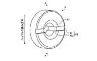
図5は、図2に記載したスリーブの変形例を示す斜視図である。図6は、旋回スクロールの旋回方向と、軸受に作用する荷重との関係を示す説明図である。図7は、図5に記載したスリーブの変形例を示す斜視図である。[Asymmetric structure of sleeve]
FIG. 5 is a perspective view showing a modified example of the sleeve described in FIG. 2. FIG. 6 is an explanatory diagram showing the relationship between the turning direction of the orbiting scroll and the load acting on the bearing. FIG. 7 is a perspective view showing a modified example of the sleeve shown in FIG.
図2の実施の形態では、スリーブ8が、周方向に一様な断面形状を有する円筒部材から成る(図3参照)。かかる構成では、スリーブ8を簡易かつ安価に製造できる点で好ましい。 In the embodiment of FIG. 2, the
しかし、これに限らず、スリーブ8が以下の構成を有しても良い。 However, the present invention is not limited to this, and the
すなわち、旋回スクロール4の旋回運動時には、旋回スクロール4からの荷重がドライブピン54に対して旋回半径方向外側に向かって作用する(図6参照)。すると、旋回スクロール4の旋回方向を基準として旋回半径方向外側に110±45[°]の範囲が荷重負荷圏となる。このため、旋回スクロール4からの荷重は、方向性を有し、シャフト51に対して一定方向に作用する。このため、シャフト51の撓み方向が一定となる。 That is, during the orbiting motion of the orbiting scroll 4, the load from the orbiting scroll 4 acts on the
そこで、スリーブ8が、所定方向に拡幅した幅広形状(周方向非対称構造)を有する(図5参照)。そして、スリーブ8が、その拡幅方向をシャフト51の撓み方向に一致させて、シャフト51に嵌め合わされる。これにより、所定方向に対するシャフト51の曲げ剛性が増加して、シャフトの撓みが効果的に低減される。 Therefore, the
例えば、図5の変形例では、スリーブ8が、小判型の幅広形状を有することにより、所定方向に対して大きな断面二次モーメントを有する。また、スリーブ8の拡幅方向が旋回スクロール4からシャフト51への荷重方向に略一致するように(±90[deg]の範囲内にあるように)、スリーブ8がシャフト51に嵌め合わされる。これにより、荷重方向に対するシャフト51の剛性が補強されて、シャフトの撓みが抑制される。 For example, in the modification of FIG. 5, the
また、例えば、図7の変形例では、スリーブ8が所定方向に偏心した偏心構造を有する。具体的には、図5の変形例において、スリーブ8が、幅広方向に偏心した構造を有する。そして、スリーブ8が、その偏心方向をシャフト51の撓み方向に対して反対側に向けて、シャフト51に嵌め合わされる。かかる構成では、スリーブ8が偏心構造を有するので、シャフト51の回転時にて、シャフト51の撓み方向に対して反対方向に遠心力が発生する。これにより、シャフト51の変形が相殺されて、シャフトの撓みが抑制される。 Further, for example, in the modification of FIG. 7, the
[スリーブの潤滑油路]
図8〜図10は、図2に記載したスリーブの変形例を示す説明図である。これらの図において、図8は、スリーブをシャフトに取り付けた状態を示し、図9および図10は、スリーブの単体を示している。[Sleeve lubricating oil passage]
8-10 is explanatory drawing which shows the modification of the sleeve described in FIG. In these drawings, FIG. 8 shows a state in which the sleeve is attached to the shaft, and FIGS. 9 and 10 show a single body of the sleeve.
図2の実施の形態では、スリーブ8が単純かつ肉厚な円筒形状を有する(図3参照)。あるいは、スリーブ8が、図3の構成において、シャフト51の拡径部512側にかかる内周面端部に面取部81を有する(図4参照)。かかる構成では、スリーブ8の加工成形が容易な点で好ましい。 In the embodiment of FIG. 2, the
しかし、これに限らず、スリーブ8が、ハウジング2の内壁面に沿った外周形状を有しても良い(図8参照)。これにより、スリーブ8を大きくして、シャフト51の撓みを効果的に抑制できる。 However, the present invention is not limited to this, and the
例えば、図8の変形例では、スリーブ8が、リップシール71側に段差部82を有することにより、ハウジング2の内壁面に沿った端部形状を有する(図8および図10参照)。具体的には、フロントケース21が一方の端部に開口部211を有し、シャフト51がこの開口部211にてフロントケース21を挿通し、また、リップシール71がこの開口部211の内壁面に配置されてシャフト51の外周の隙間を封止する。また、スリーブ8の段差部82が、この開口部211の縁部に沿った形状を有し、この開口部211とシャフト本体511との隙間に挿入される。したがって、図2の実施の形態と比較して、スリーブ8が段差部82の分だけ軸方向に延長されており、その重量が増加している。なお、スリーブ8の段差部82と、フロントケース21の開口部211との間には、クリアランスが形成されて、これらの非接触状態が確保される。 For example, in the modification of FIG. 8, the
一方で、上記の構成では、スリーブ8がフロントケース21の開口部211を略塞ぐため、メイン軸受52側からリップシール71側への潤滑油路がスリーブ8により遮断されるおそれがある。 On the other hand, in the above configuration, since the
そこで、上記の構成では、スリーブ8がメイン軸受52側からリップシール71側に抜ける油溝83を有しても良い(図8〜図10参照)。これにより、メイン軸受52側からリップシール71側への潤滑油路が確保される。 Therefore, in the above configuration, the
例えば、図8の変形例では、スリーブ8の油溝83が、第一油溝部831および第二油溝部832を有する(図9および図10参照)。第一油溝部831は、シャフト51の拡径部512側にあるスリーブ8の端面を径方向に横断して、スリーブ8の外周面に開口する。第二油溝部832は、スリーブ8の内周面を軸方向に横断し、一方の端部にて第一油溝部831に接続し、他方の端部にてスリーブ8の端面に開口する。そして、スリーブ8が、第一油溝部831側の端面をシャフト51の拡径部512の端面に当接させてシャフト51に嵌め合わされる。すると、第一油溝部831が、スリーブ8の端面とシャフト51の拡径部512の端面との間に潤滑油路を形成し、また、第二油溝部832が、スリーブ8の内周面とシャフト本体511の外周面との間に潤滑油路を形成する。そして、第一油溝部831および第二油溝部832が連通することにより、メイン軸受52側からリップシール71側への潤滑油路が形成される。 For example, in the modification of FIG. 8, the
また、上記の構成では、油溝83が、シャフト51の撓み方向から外れた位置に配置されることが好ましい(図9参照)。具体的には、油溝83の第一油溝部831および第二油溝部832が、いずれもシャフト51の撓み方向に対して直交する位置に配置される。これにより、シャフト51の撓み方向に対するスリーブ8の剛性が確保されるので、スリーブ8がシャフト51の撓みを効果的に抑制できる。 Moreover, in said structure, it is preferable that the
[効果]
以上説明したように、このスクロール流体機械1は、固定スクロール3および旋回スクロール4と、旋回スクロール4に動力を伝達するシャフト51と、固定スクロール3、旋回スクロール4およびシャフト51を収容するハウジング2とを備える(図1参照)。また、スクロール流体機械1は、ハウジング2に設置されてシャフト51を回転可能に支持するメイン軸受52およびサブ軸受53と、メイン軸受52およびサブ軸受53の間に配置されてハウジング2とシャフト51との隙間を封止するリップシール71と、メイン軸受52およびリップシール71の間でシャフト51に嵌め込まれてシャフト51の剛性を補強するスリーブ8とを備える(図2および図3参照)。[effect]
As described above, the scroll fluid machine 1 includes the fixed scroll 3 and the orbiting scroll 4, the
かかる構成では、スリーブ8がシャフト51の剛性を補強するので、高速回転時および高負荷化時におけるシャフト51の撓みが抑制される。これにより、製品の信頼性が向上する利点がある。また、かかる構成では、スリーブ8がシャフト51に対して別体で構成されるので、スクロール流体機械1の仕様や冷媒の種類に応じてスリーブ8を選択できる。したがって、シャフト自身を拡径する構成と比較して、シャフト51の剛性を適正に補強できる利点がある。 In such a configuration, since the
特に、メイン軸受52とサブ軸受53との間にリップシール71が配置される構成では、リップシール71の封止性能を確保するために、この区間におけるシャフト51の外径が小さく設定される(図2参照)。このため、メイン軸受52からリップシール71まで区間で、シャフト51が撓み易い。この点において、上記の構成では、スリーブ8がメイン軸受52およびリップシール71の間に嵌め込まれてシャフト51の剛性を補強するので、リップシール71の封止性能を確保しつつ、シャフト51の撓みを効果的に抑制できる利点がある。 In particular, in the configuration in which the
また、このスクロール流体機械1では、スリーブ8が、シャフト51の撓み方向に拡幅した幅広形状を有する(図5参照)。これにより、撓み方向に対するシャフト51の剛性が補強されて、シャフトの撓みが抑制される利点がある。 Moreover, in this scroll fluid machine 1, the
また、このスクロール流体機械1では、スリーブ8が、シャフト51の撓み方向に対して反対方向に偏心した偏心構造を有する(図7参照)。これにより、シャフト51の変形が相殺されて、シャフトの撓みが抑制される利点がある。 Further, in the scroll fluid machine 1, the
また、このスクロール流体機械1では、スリーブ8が、ハウジング2の内壁面に沿った外周形状を有する(図8および図10参照)。これにより、スリーブ8を大きくできるので、シャフトの撓みを効果的に抑制できる利点がある。 Moreover, in this scroll fluid machine 1, the
また、このスクロール流体機械1は、スリーブ8が、メイン軸受52側からリップシール71側に抜ける油溝83を有する(図8〜図10参照)。これにより、メイン軸受52側からリップシール71側への潤滑油路が確保される利点がある。 In the scroll fluid machine 1, the
1 スクロール流体機械
2 ハウジング
21 フロントケース
211 開口部
22 リアケース
23 吸入口
24 吐出口
25 吸入室
26 吐出室
3 固定スクロール
31 端板
32 ラップ
4 旋回スクロール
41 端板
42 ラップ
5 動力伝達機構
51 シャフト
511 シャフト本体
512 拡径部
52 メイン軸受
53 サブ軸受
54 ドライブピン
55 ドライブブッシュ
56 ドライブ軸受
57 バランスウェイト
58 自転防止ピン
6 駆動機構
61 回転板
7 軸封構造
71 リップシール
8 スリーブ
81 面取部
82 段差部
83 油溝
831 第一油溝部
832 第二油溝部
S 圧縮室1 scroll fluid machine 2
Claims (5)
Translated fromJapanese前記ハウジングに設置されて前記シャフトを回転可能に支持するメイン軸受およびサブ軸受と、前記メイン軸受および前記サブ軸受の間に配置されて前記ハウジングと前記シャフトとの隙間を封止するリップシールと、前記メイン軸受および前記リップシールの間に配置されると共に前記シャフトに嵌め込まれて前記シャフトの剛性を補強するスリーブとを備えることを特徴とするスクロール流体機械。A scroll fluid machine comprising: a fixed scroll and a turning scroll; a shaft that transmits power to the turning scroll; and a housing that houses the fixed scroll, the turning scroll, and the shaft;
A main bearing and a sub-bearing that are installed in the housing and rotatably support the shaft; and a lip seal that is disposed between the main bearing and the sub-bearing and seals a gap between the housing and the shaft; A scroll fluid machine, comprising: a sleeve disposed between the main bearing and the lip seal and fitted into the shaft to reinforce the rigidity of the shaft.
Priority Applications (1)
| Application Number | Priority Date | Filing Date | Title |
|---|---|---|---|
| JP2011053295AJP2012189004A (en) | 2011-03-10 | 2011-03-10 | Scroll fluid machine |
Applications Claiming Priority (1)
| Application Number | Priority Date | Filing Date | Title |
|---|---|---|---|
| JP2011053295AJP2012189004A (en) | 2011-03-10 | 2011-03-10 | Scroll fluid machine |
Publications (1)
| Publication Number | Publication Date |
|---|---|
| JP2012189004Atrue JP2012189004A (en) | 2012-10-04 |
Family
ID=47082437
Family Applications (1)
| Application Number | Title | Priority Date | Filing Date |
|---|---|---|---|
| JP2011053295AWithdrawnJP2012189004A (en) | 2011-03-10 | 2011-03-10 | Scroll fluid machine |
Country Status (1)
| Country | Link |
|---|---|
| JP (1) | JP2012189004A (en) |
Cited By (3)
| Publication number | Priority date | Publication date | Assignee | Title |
|---|---|---|---|---|
| JP2017061922A (en)* | 2015-07-01 | 2017-03-30 | プファイファー・ヴァキューム・ゲーエムベーハー | Split flow vacuum pump |
| JP2017198088A (en)* | 2016-04-25 | 2017-11-02 | 日立ジョンソンコントロールズ空調株式会社 | Rotary compressor |
| CN111237188A (en)* | 2018-11-29 | 2020-06-05 | 艾默生环境优化技术(苏州)有限公司 | Scroll compressor and method for positioning non-orbiting scroll member of scroll compressor |
- 2011
- 2011-03-10JPJP2011053295Apatent/JP2012189004A/ennot_activeWithdrawn
Cited By (4)
| Publication number | Priority date | Publication date | Assignee | Title |
|---|---|---|---|---|
| JP2017061922A (en)* | 2015-07-01 | 2017-03-30 | プファイファー・ヴァキューム・ゲーエムベーハー | Split flow vacuum pump |
| JP2017198088A (en)* | 2016-04-25 | 2017-11-02 | 日立ジョンソンコントロールズ空調株式会社 | Rotary compressor |
| CN111237188A (en)* | 2018-11-29 | 2020-06-05 | 艾默生环境优化技术(苏州)有限公司 | Scroll compressor and method for positioning non-orbiting scroll member of scroll compressor |
| CN111237188B (en)* | 2018-11-29 | 2024-04-26 | 谷轮环境科技(苏州)有限公司 | Scroll compressor and positioning method for non-orbiting scroll part of scroll compressor |
Similar Documents
| Publication | Publication Date | Title |
|---|---|---|
| JP4859730B2 (en) | Scroll compressor | |
| JP5581440B2 (en) | Scroll compressor | |
| JP6628957B2 (en) | Scroll compressor | |
| JP2017078361A (en) | Scroll fluid machine | |
| JP6715722B2 (en) | Scroll compressor | |
| JP6862294B2 (en) | Scroll compressor | |
| JP6554926B2 (en) | Scroll compressor | |
| KR101335427B1 (en) | Scroll compressor | |
| JP5455763B2 (en) | Scroll compressor, refrigeration cycle equipment | |
| CN209943089U (en) | Scroll compressor having a discharge port | |
| US9322403B2 (en) | Compressor | |
| JP2012189004A (en) | Scroll fluid machine | |
| EP3647594B1 (en) | Compressor | |
| WO2014051102A1 (en) | Scroll compressor | |
| JP6906887B2 (en) | Scroll fluid machine | |
| WO2015049745A1 (en) | Scroll compressor | |
| JP2017078360A (en) | Scroll fluid machinery | |
| JP2018096253A (en) | Scroll compressor | |
| JP6541708B2 (en) | Rolling cylinder positive displacement compressor | |
| KR20210129535A (en) | A compressor | |
| JP6679399B2 (en) | Scroll compressor | |
| JP5773922B2 (en) | Scroll compressor | |
| KR102522647B1 (en) | Sliding bush of scroll compressor | |
| JP2011231687A (en) | Scroll compressor | |
| JP2012082714A (en) | Scroll compressor |
Legal Events
| Date | Code | Title | Description |
|---|---|---|---|
| A300 | Withdrawal of application because of no request for examination | Free format text:JAPANESE INTERMEDIATE CODE: A300 Effective date:20140513 |