Movatterモバイル変換


[0]ホーム

URL:


JP2012188104A - Method for operating vehicle moving device - Google Patents

Method for operating vehicle moving device
Download PDF

Info

Publication number
JP2012188104A
JP2012188104AJP2011076524AJP2011076524AJP2012188104AJP 2012188104 AJP2012188104 AJP 2012188104AJP 2011076524 AJP2011076524 AJP 2011076524AJP 2011076524 AJP2011076524 AJP 2011076524AJP 2012188104 AJP2012188104 AJP 2012188104A
Authority
JP
Japan
Prior art keywords
vehicle
carriage
wheel
leader
follower
Prior art date
Legal status (The legal status is an assumption and is not a legal conclusion. Google has not performed a legal analysis and makes no representation as to the accuracy of the status listed.)
Granted
Application number
JP2011076524A
Other languages
Japanese (ja)
Other versions
JP5603821B2 (en
Inventor
Kazuhiro Kosuge
一弘 小菅
Yasuhisa Hirata
泰久 平田
Yusuke Sugawara
雄介 菅原
Naoaki Yonezawa
直晃 米澤
Koji Kashiwazaki
耕志 柏崎
Takashi Kanbayashi
隆 神林
Kimimoto Suzuki
公基 鈴木
Kazunori Murakami
和則 村上
Kenichi Nakamura
健一 中村
Masaki Nakanishi
正樹 中西
Hiroshi Endo
央 遠藤
Current Assignee (The listed assignees may be inaccurate. Google has not performed a legal analysis and makes no representation or warranty as to the accuracy of the list.)
Tohoku University NUC
IHI Transport Machinery Co Ltd
Original Assignee
Tohoku University NUC
IHI Transport Machinery Co Ltd
Priority date (The priority date is an assumption and is not a legal conclusion. Google has not performed a legal analysis and makes no representation as to the accuracy of the date listed.)
Filing date
Publication date
Application filed by Tohoku University NUC, IHI Transport Machinery Co LtdfiledCriticalTohoku University NUC
Priority to JP2011076524ApriorityCriticalpatent/JP5603821B2/en
Publication of JP2012188104ApublicationCriticalpatent/JP2012188104A/en
Application grantedgrantedCritical
Publication of JP5603821B2publicationCriticalpatent/JP5603821B2/en
Expired - Fee Relatedlegal-statusCriticalCurrent
Anticipated expirationlegal-statusCritical

Links

Images

Classifications

Landscapes

Abstract

PROBLEM TO BE SOLVED: To provide a method for operating a vehicle moving device, achieving movement with high accuracy by lifting up one of the front wheel and rear wheel of a vehicle by a leader truck and a follower truck, while estimating the wheel base of the vehicle, by applying force control.SOLUTION: The vehicle moving device includes: the leader truck A which has a truck body 2 self-traveling in all directions by a travel driving device, and a lifter 5 attached to the truck body 2 through a connecting mechanism and lifting up one wheel 4a of the vehicle 4, and which moves along a given target track; and the follower truck B which has the truck body 2 self-traveling in all directions by the travel driving device, and the lifter 5 attached to the truck body 2 through the connecting mechanism and lifting up one wheel 4a of the vehicle 4 other than wheels lifted up by the leader truck A, and which moves the vehicle in cooperation with the leader truck A by following while estimating movement of the leader truck A.

Description

Translated fromJapanese

本発明は、車両移動装置の運転方法に関するものである。  The present invention relates to a driving method of a vehicle moving device.

従来、任意の位置に停車した車両を駐車施設における所定位置に搬送できるようにした入出車装置の一般的技術水準を示すものとしては、例えば、特許文献1がある。  For example, Patent Document 1 shows a general technical level of an entry / exit device that can transport a vehicle stopped at an arbitrary position to a predetermined position in a parking facility.

特許文献1に示される装置は、それぞれ車両支持機構及び走行機構を備える左側搬送台車と右側搬送台車とからなり、該左側搬送台車と右側搬送台車とがそれぞれ独立して移動しつつ、協働して車両を支持し、搬送するようになっている。  The apparatus shown in Patent Document 1 includes a left conveyance carriage and a right conveyance carriage each having a vehicle support mechanism and a traveling mechanism, and the left conveyance carriage and the right conveyance carriage cooperate with each other while moving independently. The vehicle is supported and transported.

前記左側搬送台車と右側搬送台車は、無線通信によってリアルタイムに情報交換を行うことにより、協働している。  The left transport cart and the right transport cart cooperate by exchanging information in real time by wireless communication.

しかしながら、前述の如く、無線通信による台車相互間でのリアルタイムの情報交換に基づいて前記左側搬送台車と右側搬送台車とを協働させるのでは、通信障害で情報が途切れたり遅れたりすることもあり、前記左側搬送台車と右側搬送台車とを協働させるために必要な情報をリアルタイムに安定して得ることが難しかった。又、情報が安定して得られなかった場合、搬送される車両等の物体に必要以上の内力が加わることとなり、最悪の場合、物体を落としたり、傷つけたりする可能性があった。  However, as described above, if the left transport cart and the right transport cart cooperate based on real-time information exchange between the carts by wireless communication, information may be interrupted or delayed due to communication failure. It is difficult to stably obtain information necessary for cooperating the left and right transport carts in real time. In addition, when information is not stably obtained, an internal force more than necessary is applied to an object such as a vehicle being conveyed, and in the worst case, the object may be dropped or damaged.

このため、本発明者等は、無線通信のみによる台車相互間でのリアルタイムの情報交換を行うようにした協働搬送とは異なり、車両等の物体を落としたり、傷つけたりする心配がなく、複数の台車を協調制御により作動させることで、車両等の物体を確実に且つより安定して移動させ得る物体移動装置を提案している。(例えば、特許文献2参照。)  For this reason, the present inventors do not have to worry about dropping or damaging an object such as a vehicle, unlike collaborative conveyance in which real-time information exchange is performed between trolleys using only wireless communication. The object moving apparatus which can move objects, such as a vehicle reliably, more stably by operating this cart by cooperative control is proposed. (For example, seePatent Document 2.)

前記特許文献2に開示した物体移動装置は、複数の台車を協調制御により作動させるという非常に高度で優れた機能を有するものである反面、移動すべき物体がバス等のホイールベースの長い車両や接地ポイントとしての車輪の数が多い車両であった場合、移動装置自体を大きくしたり、車輪の数に合わせた機構のものを別途用意しなければならず、移動装置の種類が増える一方、移動装置が大型化した場合には、移動経路を広くとり、且つ保管スペースも広く必要になるという欠点を有していた。  Although the object moving device disclosed inPatent Document 2 has a very advanced and excellent function of operating a plurality of carriages by cooperative control, the object to be moved is a vehicle having a long wheelbase such as a bus, If the vehicle has a large number of wheels as the ground contact point, the moving device itself must be enlarged or a mechanism that matches the number of wheels must be prepared separately. When the apparatus is increased in size, there is a disadvantage that a wide movement path and a large storage space are required.

そこで、本発明者等は、車両等の物体の一つの接地ポイントとしての車輪をリフトアップし、与えられた目標軌道に沿って移動可能なリーダ台車と、該リーダ台車にてリフトアップされる車輪以外の一つの車輪をリフトアップする複数台のフォロワ台車とを備えることにより、大きさや接地ポイント数の異なる車両等の物体にも装置の種類を増やすことなく対応し得、車両等の物体を確実に且つより安定して移動させることができ、移動経路や保管スペースの削減をも図り得る物体移動装置を提案している。(例えば、特許文献3参照。)  Therefore, the present inventors have lifted up a wheel as one contact point of an object such as a vehicle, and moved along a given target trajectory, and a wheel lifted up by the leader cart. By providing multiple follower carts that lift up one wheel other than the above, it is possible to cope with objects such as vehicles with different sizes and grounding points without increasing the number of types of devices, and reliably In addition, an object moving device has been proposed that can be moved more stably and can reduce the movement route and storage space. (For example, refer toPatent Document 3.)

特開2004−169451号公報JP 2004-169451 A特開2009−108542号公報JP 2009-108542 A特開2009−286570号公報JP 2009-286570 A

ところで、前輪と後輪の四個の車輪を有する車両に着目すると、基本的には後輪のサイドブレーキを開放して前輪だけを持ち上げれば、車両を運ぶことができ、必ずしも全ての車輪を持ち上げる必要はない。  By the way, paying attention to a vehicle having four wheels, a front wheel and a rear wheel, basically, the vehicle can be transported by lifting only the front wheel by releasing the side brake of the rear wheel, and not all wheels are There is no need to lift.

即ち、特許文献3に記載されているように通常四台の台車が車両の各車輪をリフトアップするシステムを配備した駐車施設において、状況に応じて二台ずつ二組の台車が複数の車両を並行作業で移動させることが実際に行えるのであれば、更なる効率化が期待できるという点に本発明者等は着目した。  That is, as described inPatent Document 3, in a parking facility where a system in which four trucks normally lift up each wheel of a vehicle is deployed, two sets of two trucks each have a plurality of vehicles depending on the situation. The present inventors paid attention to the point that further efficiency can be expected if the movement can be actually performed in parallel work.

しかしながら、このように車両を運ぶ際の最大の問題は、車両の後輪が接地することによりシステムが非ホロノミックな拘束を受ける点にある。  However, the biggest problem in carrying the vehicle in this way is that the system is subjected to non-holonomic restraint due to the rear wheel of the vehicle being in contact with the ground.

そこで、本発明者等は、車両の前輪又は後輪のいずれか一方の車輪をリーダ台車とフォロワ台車とによってリフトアップし、該リーダ台車とフォロワ台車の制御点を前記車両のリフトアップされる二個の車輪の中点に設定し、前記車両を含めたシステム全体を、前記中点に設定され且つ能動的に全方向へ速度を発生可能な仮想キャスタと、前記車両の接地している側の対向する二個の車輪とによって構成される三輪車モデルに見立てて位置制御するようにした車両移動装置の運転方法を開発し、既に出願している(特願2010−273698参照)。  Accordingly, the present inventors lift up either the front wheel or the rear wheel of the vehicle with a leader carriage and a follower carriage, and control points of the leader carriage and the follower carriage are lifted up. Set to the midpoint of the wheels, and the entire system including the vehicle is set to the midpoint and is capable of actively generating speed in all directions, and the grounded side of the vehicle A driving method for a vehicle moving device has been developed and applied for in consideration of the position of a tricycle model composed of two wheels facing each other (see Japanese Patent Application No. 2010-273698).

本発明者等が既に出願している前記車両移動装置の運転方法においては、前記制御点に速度入力を与えたときの該制御点の運動を求める上で車両のホイールベースを知る必要がある。  In the driving method of the vehicle moving device already filed by the present inventors, it is necessary to know the wheel base of the vehicle in order to obtain the motion of the control point when a speed input is given to the control point.

しかしながら、実際には搬送の対象となる車種は非常に多く、そのホイールベースも様々である。このため、例えば、データベースとしてホイールベースを知識化する方法が考えられるが、この場合、車種を特定する装置の導入、或いは利用者に車種の入力を求めることが必要となり、手間がかかり、あまり好ましい手段であるとは言えなかった。又、カメラ等のセンサにより寸法を計測する方法も考えられるが、測定誤差や車体の弾性による寸法の変化が生じる可能性があり、必ずしも充分であるとは言えなかった。  However, there are actually a large number of vehicles that are transported, and the wheelbases are also various. For this reason, for example, a method of making the wheelbase knowledgeable as a database is conceivable, but in this case, it is necessary to introduce a device for identifying the vehicle type or to require the user to input the vehicle type, which is troublesome and is not preferable. It could not be said that it was a means. Although a method of measuring the dimensions with a sensor such as a camera is conceivable, there is a possibility that a change in dimensions due to a measurement error or the elasticity of the vehicle body may occur, which is not always sufficient.

本発明は、斯かる実情に鑑み、力制御を適用することにより、車両のホイールベースを推定しつつ、該車両の前輪又は後輪のいずれか一方の車輪をリーダ台車とフォロワ台車とによりリフトアップして精度良く移動させることができる車両移動装置の運転方法を提供しようとするものである。  In view of such circumstances, the present invention lifts up one of the front wheels and the rear wheels of the vehicle with a leader carriage and a follower carriage while estimating the wheel base of the vehicle by applying force control. Thus, an object of the present invention is to provide a driving method for a vehicle moving device that can be moved with high accuracy.

本発明は、走行駆動装置により全方向に自走可能な台車本体と、該台車本体に連結機構を介して取り付けられ且つ車両の一つの車輪をリフトアップするリフターとを有し、与えられた目標軌道に沿って移動可能なリーダ台車と、
走行駆動装置により全方向に自走可能な台車本体と、該台車本体に連結機構を介して取り付けられ且つ前記車両の前記リーダ台車にてリフトアップされる車輪以外の一つの車輪をリフトアップするリフターとを有し、前記リーダ台車の動きを推定しつつ追従することにより、該リーダ台車と協調して車両を移動させるフォロワ台車とを備え、
前記車両の前輪又は後輪のいずれか一方の車輪を前記リーダ台車とフォロワ台車とによってリフトアップし、該リーダ台車とフォロワ台車の制御点を前記車両のリフトアップされる二個の車輪の中点に設定し、前記車両を含めたシステム全体を、前記中点に設定され且つ能動的に全方向へ速度を発生可能な仮想キャスタと、前記車両の接地している側の対向する二個の車輪とによって構成される三輪車モデルに見立てて位置制御する車両移動装置の運転方法であって、
前記リーダ台車とフォロワ台車を前記制御点回りにインピーダンス制御して[数20]に示す運動を行わせ、

Figure 2012188104
Figure 2012188104
送するために制御点に生じさせたい絶対座標系O−x’y’(車両の進行方向をx’とし、x’と垂直な方向をy’とした座標系)から見た目標速度)
Figure 2012188104
Figure 2012188104
Figure 2012188104
Figure 2012188104
Figure 2012188104
想定ホイールベースLintを実時間で計算することにより、最終的に想定ホイールベースLintを実際のホイールベースLrealに収束させ、該実際のホイールベースLrealを推定することを特徴とする車両移動装置の運転方法にかかるものである。The present invention has a cart body that can be self-propelled in all directions by a travel drive device, and a lifter that is attached to the cart body via a coupling mechanism and lifts up one wheel of the vehicle, and has a given target A leader carriage movable along the track;
A carriage main body capable of self-propelling in all directions by a traveling drive device, and a lifter for lifting one wheel other than the wheel attached to the carriage main body via a coupling mechanism and lifted up by the leader carriage of the vehicle A follower carriage that moves the vehicle in cooperation with the leader carriage by following the movement while estimating the movement of the leader carriage.
The wheel of either the front wheel or the rear wheel of the vehicle is lifted by the leader carriage and the follower carriage, and the control point of the leader carriage and the follower carriage is the midpoint of the two wheels to be lifted by the vehicle The entire system including the vehicle, the virtual caster set at the midpoint and capable of actively generating speed in all directions, and the two wheels facing each other on the grounding side of the vehicle A driving method of a vehicle moving device that controls the position of a tricycle model constituted by:
Impedance control of the leader carriage and the follower carriage around the control point is performed as shown in [Equation 20],
Figure 2012188104
Figure 2012188104
The target speed as seen from the absolute coordinate system O-x'y ' (the coordinate system in which the vehicle traveling direction is x' and the direction perpendicular to x 'is y') to be generated at the control point for transmission
Figure 2012188104
Figure 2012188104
Figure 2012188104
Figure 2012188104
Figure 2012188104
Vehicle movement characterized by calculating the assumed wheelbase Lint in real time to finally converge the assumed wheelbase Lint to the actual wheel base Lreal and estimating the actual wheel base Lreal This is related to the operation method of the apparatus.

本発明の車両移動装置の運転方法を利用すれば、前記制御点に速度入力を与えたときの該制御点の運動を求める上で知る必要のある車両のホイールベースを、例えば、データベースとしてホイールベースを知識化したりすることなく、推定可能となるため、車種を特定する装置の導入、或いは利用者に車種の入力を求めることが不要となり、手間がかからなくなる。又、カメラ等のセンサにより寸法を計測する方法も導入しなくて済むため、測定誤差や車体の弾性による寸法の変化が生じることに伴う不具合が生じる心配もない。  If the driving method of the vehicle moving apparatus of the present invention is used, the wheel base of the vehicle that needs to be known for obtaining the motion of the control point when a speed input is given to the control point, for example, the wheel base as a database. Therefore, it is not necessary to introduce a device for identifying the vehicle type or to ask the user to input the vehicle type, and it is not time-consuming. In addition, since it is not necessary to introduce a method for measuring dimensions with a sensor such as a camera, there is no fear of causing problems due to measurement errors and changes in dimensions due to elasticity of the vehicle body.

本発明の車両移動装置の運転方法によれば、力制御を適用することにより、車両のホイールベースを推定しつつ、該車両の前輪又は後輪のいずれか一方の車輪をリーダ台車とフォロワ台車とによりリフトアップして精度良く移動させることができるという優れた効果を奏し得る。  According to the driving method of the vehicle moving device of the present invention, by applying force control, the wheel base of the vehicle is estimated, and either the front wheel or the rear wheel of the vehicle is set as a leader carriage and a follower carriage. Therefore, it is possible to achieve an excellent effect of being able to lift up and move with high accuracy.

本発明の車両移動装置の運転方法の実施例を示す全体概要斜視図である。BRIEF DESCRIPTION OF THE DRAWINGS FIG.本発明の車両移動装置の運転方法の実施例におけるリーダ台車(フォロワ台車)を示す斜視図である。It is a perspective view which shows the leader trolley | bogie (follower trolley | bogie) in the Example of the driving | running method of the vehicle moving apparatus of this invention.本発明の車両移動装置の運転方法の実施例におけるリーダ台車(フォロワ台車)を底面側から示す斜視図である。It is a perspective view which shows the leader trolley | bogie (follower trolley | bogie) in the Example of the operating method of the vehicle moving apparatus of this invention from the bottom face side.本発明の車両移動装置の運転方法の実施例におけるリーダ台車(フォロワ台車)の連結機構を示す斜視図である。It is a perspective view which shows the connection mechanism of the leader trolley (follower trolley | bogie) in the Example of the driving | running method of the vehicle moving apparatus of this invention.本発明の車両移動装置の運転方法の実施例におけるリーダ台車(フォロワ台車)のリフターの車輪浮上支持装置を示す斜視図である。It is a perspective view which shows the wheel floating support apparatus of the lifter of the leader trolley | bogie (follower trolley | bogie) in the Example of the driving | running method of the vehicle moving apparatus of this invention.本発明の車両移動装置の運転方法の実施例におけるリーダ台車の全体制御系統並びにフォロワ台車の全体制御系統を示すブロック図である。It is a block diagram which shows the whole control system of the leader trolley | bogie in the Example of the driving | running method of the vehicle moving apparatus of this invention, and the whole control system of a follower trolley | bogie.本発明の車両移動装置の運転方法の実施例におけるリーダ台車とフォロワ台車の協調制御に関するシステム図である。It is a system diagram regarding the cooperative control of the leader carriage and the follower carriage in the embodiment of the driving method of the vehicle moving apparatus of the present invention.本発明の車両移動装置の運転方法の実施例における各連結機構の配置を示す平面図である。It is a top view which shows arrangement | positioning of each connection mechanism in the Example of the driving | running method of the vehicle moving apparatus of this invention.本発明の車両移動装置の運転方法の実施例におけるシステム全体の幾何モデル図である。It is a geometric model figure of the whole system in the Example of the driving | running method of the vehicle moving apparatus of this invention.本発明の車両移動装置の運転方法の実施例におけるホイールベースの推定アルゴリズムを示すブロック図である。It is a block diagram which shows the estimation algorithm of a wheel base in the Example of the driving | running method of the vehicle moving apparatus of this invention.

以下、本発明の実施の形態を添付図面を参照して説明する。  Embodiments of the present invention will be described below with reference to the accompanying drawings.

図1〜図10は本発明の車両移動装置の運転方法の実施例であって、
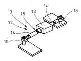
走行駆動装置1により全方向に自走可能な台車本体2と、該台車本体2に連結機構3を介して取り付けられ且つ物体としての車両4の一つの車輪4aをリフトアップするリフター5とを有し、与えられた目標軌道に沿って移動可能なリーダ台車Aと、
走行駆動装置1により全方向に自走可能な台車本体2と、該台車本体2に連結機構3を介して取り付けられ且つ前記車両4の前記リーダ台車Aにてリフトアップされる車輪4a以外の一つの車輪4aをリフトアップするリフター5とを有し、前記リーダ台車Aの動きを推定しつつ追従することにより、該リーダ台車Aと協調して車両4を移動させるフォロワ台車Bとを備えてなる車両移動装置を利用するようにしたものである。
FIGS. 1-10 is an Example of the driving | running method of the vehicle moving apparatus of this invention, Comprising:
A carriagemain body 2 capable of self-propelling in all directions by the traveling drive device 1 and alifter 5 attached to the carriagemain body 2 via aconnecting mechanism 3 and lifting up one wheel 4a of thevehicle 4 as an object are provided. A leader carriage A movable along a given target trajectory;
A carriagemain body 2 that can be self-propelled in all directions by the travel drive device 1 and a wheel 4a that is attached to the carriagemain body 2 via acoupling mechanism 3 and lifted up by the leader carriage A of the vehicle 4 Alifter 5 that lifts up the four wheels 4a, and a follower carriage B that moves thevehicle 4 in cooperation with the leader carriage A by following the movement while estimating the movement of the leader carriage A. A vehicle moving device is used.

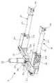
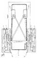
前記台車本体2は、図1〜図3に示す如く、直方体の四隅部をカットして細長い八角柱形状に組み立てられた台車フレーム2aの四隅部に、走行駆動装置1として走行車輪6を走行モータ7(走行アクチュエータ)(図6参照)の作動により水平な車軸8を中心に回転可能に配設してなる構成を有している。尚、前記走行車輪6は、操舵を必要としないオムニホイール(登録商標)やメカナムホイール等の全方向移動車輪とし、台車本体2の幅方向(図8の左右方向)に対しそれぞれ45°の角度を持ち、且つ対角に位置する走行車輪6同士が平行となるようにしてある。又、前記走行モータ7には、軌道センサとしての走行エンコーダ11(図6参照)が一体に組み込まれ、台車本体2の実際の軌道情報を検出できるようにしてある。更に又、前記走行車輪6の全てが常に地面と接触するよう、四個のうち二個の走行車輪6はサスペンション機構6aを介して台車フレーム2aに取り付けるようにしてある。  As shown in FIGS. 1 to 3, thecart body 2 has a runningmotor 6 as a running drive device 1 at the four corners of acart frame 2 a that is assembled into an elongated octagonal prism shape by cutting four corners of a rectangular parallelepiped. 7 (traveling actuator) (see FIG. 6) is arranged to be rotatable about a horizontal axle 8. Thetraveling wheel 6 is an omnidirectional moving wheel such as an omni wheel (registered trademark) or mecanum wheel that does not require steering, and is 45 ° with respect to the width direction of the carriage body 2 (left and right direction in FIG. 8). Thetraveling wheels 6 having an angle and located diagonally are parallel to each other. Thetravel motor 7 is integrated with a travel encoder 11 (see FIG. 6) as a track sensor so that actual track information of thecart body 2 can be detected. Furthermore, two of the fourtraveling wheels 6 are attached to thecarriage frame 2a via thesuspension mechanism 6a so that all of thetraveling wheels 6 are always in contact with the ground.

前記連結機構3は、図3及び図4に示す如く、力センサとしての引張圧縮型のロードセル13の両端にロッド14を取り付けた連結部材15を、その一端がユニバーサルジョイント16により台車本体2側に連結され他端がユニバーサルジョイント16によりリフター5側に連結されるよう、同一水平面内に複数(図8の例では三個)配設してなるパラレルリンク機構17によって構成してある。この場合、前記台車本体2に対しリフター5は、図2に示す如く、水平面内におけるX−Y方向に移動する方向の2自由度と、該X−Y方向に対して直交するZ軸を中心として回転する方向の1自由度とを加えた平面3自由度が拘束され、且つX軸を中心として回転する方向の1自由度と、Y軸を中心として回転する方向の1自由度と、Z軸方向に移動する方向の1自由度とを加えた3自由度がフリーとなるよう、前記パラレルリンク機構17(図3、図4及び図8参照)を介して配置される形となる。  As shown in FIGS. 3 and 4, theconnecting mechanism 3 includes a connectingmember 15 havingrods 14 attached to both ends of a tension /compression load cell 13 as a force sensor, one end of which is connected to thecart body 2 side by auniversal joint 16. A plurality of (three in the example shown in FIG. 8)parallel link mechanisms 17 are arranged in the same horizontal plane so that the other ends are connected to thelifter 5 side by theuniversal joint 16. In this case, as shown in FIG. 2, thelifter 5 with respect to thecart body 2 has two degrees of freedom in the direction of movement in the XY direction in the horizontal plane and the Z axis orthogonal to the XY direction. 3 degrees of freedom in the plane plus one degree of freedom in the direction of rotation, and one degree of freedom in the direction of rotation around the X axis, one degree of freedom in the direction of rotation around the Y axis, and Z It is arranged via the parallel link mechanism 17 (see FIGS. 3, 4 and 8) so that three degrees of freedom including one degree of freedom in the direction of movement in the axial direction is free.

前記リフター5は、図1〜図3及び図5に示す如く、前記車両4の各車輪4aを支持するための車輪浮上支持装置18を装備し、該車輪浮上支持装置18は、前記台車本体2に対し連結機構3を介して取り付けられるリフターフレーム5aに、リニアガイドレール19を台車本体2の幅方向(図8の左右方向)へ延びるよう固定配置すると共に、該リニアガイドレール19に対し、リニアガイドブロック19aを介して一対のラック部材21を互いにそのラック部の形成面が対向した状態で前記リニアガイドレール19に沿ってスライド自在となるよう配設し、前記リフターフレーム5aの中央部に一体に設けられ両端が開放された中空箱形のベース枠5bに、エンコーダ等のリフトバー開閉センサ22が一体に設けられたモータ等のリフトバー開閉アクチュエータ23を取り付け、該リフトバー開閉アクチュエータ23によって回転駆動される駆動ピニオン24を前記一対のラック部材21の互いに対向するラック部に対し前記ベース枠5b内でその両方に噛合させ、前記リニアガイドブロック19aから、底面が開放された断面門型のカバーフレーム5cを張り出させ、該カバーフレーム5cに対し、外周に車輪支持ローラ25が回転自在に嵌装され且つ先端部と基端部に接地支持輪26が取り付けられたリフトバー27を、前記ラック部材21と直角な水平方向へ延び且つ前記リニアガイドレール19と平行な揺動軸5dを中心に揺動自在となるよう取り付けてなる構成を有し、前記リフター5の車輪浮上支持装置18における一対のリフトバー27を前記車両4の各車輪4aの前後に配置して互いに近接させることにより、該車両4をリフトアップするよう構成してある。尚、前記リフトバー27の両端に取り付けた接地支持輪26により車両4の重量全てを支持するため、台車本体2は、車両4の重量を支持できるよう頑丈に設計する必要がなくなるという利点があり、更に、前記リフトバー27をその開閉方向と平行な揺動軸5dを中心に揺動自在となるようにしているため、二本のリフトバー27に取り付けた四つの接地支持輪26は常に接地する形となり、好ましい。  As shown in FIGS. 1 to 3 and 5, thelifter 5 is equipped with a wheellevitation support device 18 for supporting each wheel 4 a of thevehicle 4, and the wheellevitation support device 18 is provided with thecart body 2. Thelinear guide rail 19 is fixedly disposed on thelifter frame 5a attached via the connectingmechanism 3 so as to extend in the width direction of the carriage main body 2 (left and right direction in FIG. 8). A pair ofrack members 21 are arranged so as to be slidable along thelinear guide rail 19 with the rack portion forming surfaces facing each other via theguide block 19a, and are integrated with the central portion of thelifter frame 5a. A lift of a motor or the like in which a lift bar opening /closing sensor 22 such as an encoder is integrally provided in a hollow box-shapedbase frame 5b provided at both ends and open. The open /close actuator 23 is attached, and thedrive pinion 24 that is rotationally driven by the lift bar open /close actuator 23 is engaged with both of the opposing rack portions of the pair ofrack members 21 within thebase frame 5b, and the linear guide From theblock 19a, a cover-type cover frame 5c having an open bottom surface is projected, and awheel support roller 25 is rotatably fitted to the outer periphery of thecover frame 5c and is grounded at the distal end and the proximal end. Thelift bar 27 to which thesupport wheel 26 is attached has a configuration in which thelift bar 27 is attached so as to be swingable about aswing shaft 5d extending in a horizontal direction perpendicular to therack member 21 and parallel to thelinear guide rail 19. Then, a pair of lift bars 27 in the wheellevitation support device 18 of thelifter 5 is connected to eachwheel 4 of thevehicle 4. By close to each other and arranged one behind the, it is configured to lift up thevehicle 4. In addition, since the entire weight of thevehicle 4 is supported by theground support wheels 26 attached to both ends of thelift bar 27, there is an advantage that thecart body 2 does not need to be designed so as to be able to support the weight of thevehicle 4, Further, since thelift bar 27 is swingable around aswing shaft 5d parallel to the opening and closing direction, the fourground support wheels 26 attached to the twolift bars 27 are always in contact with the ground. ,preferable.

前記リフトバー27の車輪支持ローラ25表面には、ローレット加工、或いは滑り止め塗料の塗装といった滑り止め加工を施すようにしてある。  The surface of thewheel support roller 25 of thelift bar 27 is subjected to anti-slip processing such as knurling or anti-slip coating.

前記接地支持輪26には、一般的なキャスタを用いるようにしてあるが、前記走行車輪6と同様に、操舵を必要としないオムニホイール(登録商標)やメカナムホイール等の全方向移動車輪を用いても良いことは言うまでもない。  A general caster is used for thegrounding support wheel 26, but an omnidirectional moving wheel such as an omni wheel (registered trademark) or a mecanum wheel that does not require steering, like thetraveling wheel 6, is used. Needless to say, it may be used.

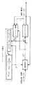
一方、図6はリーダ台車Aの全体制御系統並びにフォロワ台車Bの全体制御系統を示すブロック図であり、前記リーダ台車Aに搭載されたリーダ制御部31には、前記台車本体2の走行駆動装置1における走行アクチュエータとしての走行モータ7と、前記台車本体2の走行駆動装置1における軌道センサとしての走行エンコーダ11と、前記連結機構3の力センサとしてのロードセル13と、前記リフター5の車輪浮上支持装置18におけるリフトバー開閉アクチュエータ23と、前記リフター5の車輪浮上支持装置18におけるリフトバー開閉センサ22と、前記フォロワ台車Bへ制御情報を送信するための無線通信装置39とを接続し、前記連結機構3の力センサとしてのロードセル13による検出信号と、前記台車本体2の走行駆動装置1における軌道センサとしての走行エンコーダ11による検出信号とに基づいて、前記台車本体2の走行駆動装置1における走行アクチュエータとしての走行モータ7に駆動信号を出力すると共に、前記無線通信装置39にてフォロワ台車Bへの制御情報を送信しつつ、前記リフター5の車輪浮上支持装置18におけるリフトバー開閉センサ22による検出信号に基づいて、前記リフター5の車輪浮上支持装置18におけるリフトバー開閉アクチュエータ23に駆動信号を出力する一方、
前記フォロワ台車Bに搭載されたフォロワ制御部32には、前記台車本体2の走行駆動装置1における走行アクチュエータとしての走行モータ7と、前記台車本体2の走行駆動装置1における軌道センサとしての走行エンコーダ11と、前記連結機構3の力センサとしてのロードセル13と、前記リフター5の車輪浮上支持装置18におけるリフトバー開閉アクチュエータ23と、前記リフター5の車輪浮上支持装置18におけるリフトバー開閉センサ22と、前記リーダ台車Aからの制御情報を受信するための無線通信装置40とを接続し、前記連結機構3の力センサとしてのロードセル13による検出信号と、前記台車本体2の走行駆動装置1における軌道センサとしての走行エンコーダ11による検出信号と、前記無線通信装置40で受信したリーダ台車Aからの制御情報とに基づいて、前記台車本体2の走行駆動装置1における走行アクチュエータとしての走行モータ7に駆動信号を出力すると共に、前記リフター5の車輪浮上支持装置18におけるリフトバー開閉センサ22による検出信号に基づいて、前記リフター5の車輪浮上支持装置18におけるリフトバー開閉アクチュエータ23に駆動信号を出力するようにしてある。
On the other hand, FIG. 6 is a block diagram showing an overall control system of the leader carriage A and an overall control system of the follower carriage B. Theleader controller 31 mounted on the leader carriage A includes a travel drive device for thecarriage body 2. 1, atravel motor 7 as a travel actuator, atravel encoder 11 as a track sensor in the travel drive device 1 of thecart body 2, aload cell 13 as a force sensor of thecoupling mechanism 3, and a wheel suspension support of thelifter 5. The lift bar opening /closing actuator 23 in thedevice 18, the lift bar opening /closing sensor 22 in the wheelsuspension support device 18 of thelifter 5, and thewireless communication device 39 for transmitting control information to the follower carriage B are connected, and thecoupling mechanism 3 Detection signal by theload cell 13 as a force sensor of the vehicle and the driving of thecart body 2 Based on the detection signal from thetravel encoder 11 as the track sensor in the apparatus 1, a drive signal is output to thetravel motor 7 as the travel actuator in the travel drive device 1 of thecart body 2, and at thewireless communication device 39 While transmitting control information to the follower carriage B, a drive signal is sent to the lift bar opening /closing actuator 23 in the wheel floatingsupport device 18 of thelifter 5 based on the detection signal from the lift bar opening /closing sensor 22 in the wheel floatingsupport device 18 of thelifter 5. While outputting
Thefollower control unit 32 mounted on the follower cart B includes atravel motor 7 as a travel actuator in the travel drive device 1 of thecart body 2 and a travel encoder as a track sensor in the travel drive device 1 of thecart body 2. 11, aload cell 13 as a force sensor of thecoupling mechanism 3, a lift bar opening /closing actuator 23 in the wheellevitation support device 18 of thelifter 5, a lift bar opening /closing sensor 22 in the wheellevitation support device 18 of thelifter 5, and the reader Awireless communication device 40 for receiving control information from the carriage A is connected, a detection signal by theload cell 13 as a force sensor of thecoupling mechanism 3, and a track sensor in the traveling drive device 1 of thecarriage body 2. The detection signal from the travelingencoder 11 and thewireless communication device 40 Based on the received control information from the leader carriage A, a driving signal is output to a travelingmotor 7 as a traveling actuator in the traveling drive apparatus 1 of the carriagemain body 2 and a lift bar in the wheelsuspension support apparatus 18 of thelifter 5 is provided. Based on the detection signal from the opening /closing sensor 22, a drive signal is output to the lift bar opening /closing actuator 23 in the wheelsuspension support device 18 of thelifter 5.

前記リーダ台車Aとフォロワ台車Bの協調制御に関するシステムについてより詳しくは、図7に示す如く、前記リーダ台車Aとフォロワ台車Bとの間で車両4を介して相互に働く相互作用力を前記リーダ台車Aの力センサとしてのロードセル13により力情報として検出し、前記リーダ台車Aの台車本体2の実際の軌道情報を前記軌道センサとしての走行エンコーダ11によって検出し、前記リーダ制御部31において、予め入力される目標軌道情報と、前記リーダ台車Aの力センサとしてのロードセル13で検出された力情報と、前記リーダ台車Aの軌道センサとしての走行エンコーダ11で検出された実際の軌道情報とに基づき、前記リーダ台車Aの台車本体2の走行アクチュエータへ電流指令値を出力すると共に、前記無線通信装置39にてフォロワ台車Bへの制御情報を送信し、前記リーダ台車Aの台車本体2を目標軌道に沿って移動させる一方、
前記リーダ台車Aとフォロワ台車Bとの間で車両4を介して相互に働く相互作用力を前記フォロワ台車Bの力センサとしてのロードセル13により力情報として検出し、前記フォロワ台車Bの台車本体2の実際の軌道情報を前記軌道センサとしての走行エンコーダ11によって検出し、前記リーダ台車Aから無線通信装置39にて送信される制御情報を無線通信装置40で受信し、前記フォロワ制御部32において、前記フォロワ台車Bの力センサとしてのロードセル13で検出された力情報と、前記フォロワ台車Bの軌道センサとしての走行エンコーダ11で検出された実際の軌道情報と、前記無線通信装置40で受信したリーダ台車Aからの制御情報とに基づき、前記フォロワ台車Bの台車本体2の走行アクチュエータへ電流指令値を出力し、前記フォロワ台車Bの台車本体2を前記リーダ台車Aの動きに追従させて移動させるようにしてある。
In more detail about the system related to the cooperative control of the leader carriage A and the follower carriage B, as shown in FIG. 7, the interaction force acting between the leader carriage A and the follower carriage B via thevehicle 4 as shown in FIG. It is detected as force information by aload cell 13 as a force sensor of the carriage A, and actual trajectory information of thecarriage body 2 of the leader carriage A is detected by atravel encoder 11 as the trajectory sensor. Based on the input target trajectory information, the force information detected by theload cell 13 as the force sensor of the leader carriage A, and the actual trajectory information detected by thetravel encoder 11 as the trajectory sensor of the leader carriage A. The current command value is output to the traveling actuator of thecart body 2 of the reader cart A, and thewireless communication device 3 While at transmit control information to the follower carriage B, to move thecarriage body 2 of the leader carriage A along the target track,
The interaction force acting between the leader carriage A and the follower carriage B via thevehicle 4 is detected as force information by aload cell 13 as a force sensor of the follower carriage B, and the carriagemain body 2 of the follower carriage B is detected. Is detected by the travelingencoder 11 as the track sensor, and the control information transmitted from the reader carriage A by thewireless communication device 39 is received by thewireless communication device 40. In thefollower control unit 32, The force information detected by theload cell 13 as the force sensor of the follower carriage B, the actual track information detected by thetravel encoder 11 as the track sensor of the follower carriage B, and the reader received by thewireless communication device 40 Based on the control information from the carriage A, the current command value is output to the traveling actuator of thecarriage body 2 of the follower carriage B. And, it is to move thecarriage body 2 of the follower carriage B by following the movement of the leader carriage A.

尚、前記フォロワ台車Bの台車本体2がリーダ台車Aの動きに追従して移動するための前記ロードセル13で検出された力情報に、例えば、地面と前記リフター5の接地支持輪26との摩擦や慣性力等の外乱要素が影響を与える場合、前記リーダ台車Aの動きにフォロワ台車Bが追従しようとする動きに対し誤差を増大させてしまうので、より安定した状態で前記リーダ台車Aとフォロワ台車Bとを協調させて車両4を移動させるには、前述の如き誤差を修正するための制御情報が必要となることから、該制御情報を前記リーダ制御部31より、前記リーダ台車Aの無線通信装置39にて送信しフォロワ台車Bの無線通信装置40で受信し、フォロワ制御部32で前記誤差を修正する計算を前記制御情報に基づいて行うようにしてある。  Note that the force information detected by theload cell 13 for thecarriage body 2 of the follower carriage B to move following the movement of the leader carriage A includes, for example, the friction between the ground and theground support wheel 26 of thelifter 5. When a disturbance element such as inertia or inertia affects, an error is increased with respect to the movement of the follower carriage B following the movement of the leader carriage A. Therefore, the leader carriage A and the follower are more stably maintained. In order to move thevehicle 4 in cooperation with the carriage B, control information for correcting the error as described above is required. Therefore, the control information is transmitted from thereader control section 31 to the radio of the leader carriage A. Thecommunication device 39 transmits the data, thewireless communication device 40 of the follower carriage B receives the data, and thefollower control unit 32 performs a calculation for correcting the error based on the control information.

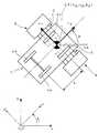
ここで、前記力センサとしての引張圧縮型のロードセル13が介装された連結部材15を平面3自由度を拘束するパラレルリンク機構17として図8に示すような配置で三つ取り付けた場合、ロードセル13による検出値をヤコビ行列で座標変換すると、外力としてリフター5に加わる力を平面3自由度の力情報として得ることができるが、具体的な計算例については、特許文献3に記載されている。  Here, when three connectingmembers 15 having the tension /compression load cell 13 as the force sensor are attached as theparallel link mechanism 17 for restraining three degrees of freedom of the plane, the load cell is attached as shown in FIG. If the detected value obtained by 13 is coordinate-transformed with a Jacobian matrix, the force applied to thelifter 5 as an external force can be obtained as force information with three degrees of freedom in the plane, but a specific calculation example is described inPatent Document 3. .

又、リーダ台車Aとフォロワ台車Bの協調制御の基本的な考え方に関しては、小菅一弘、大住智宏、千葉晋彦による「単一物体を操る複数移動ロボットの分散協調制御」、日本ロボット学会誌16巻1号、pp.87〜95に記載されている。  Also, regarding the basic concept of cooperative control of leader carriage A and follower carriage B, “Distributed cooperative control of multiple mobile robots that manipulate a single object” by Kazuhiro Komine, Tomohiro Ozumi, and Yasuhiko Chiba, Journal of the Robotics Society ofJapan 16 vol.1, pp. 87-95.

そして、本実施例の場合、図1に示す如く、前記車両4の車輪4aのうち右側の前輪を前記リーダ台車Aでリフトアップすると共に、前記車両4の車輪4aのうち左側の前輪を前記フォロワ台車Bによってリフトアップし、図9に示す如く、該リーダ台車Aとフォロワ台車Bの制御点CPを前記車両4のリフトアップされる二個の車輪4aの中点に設定し、前記車両4を含めたシステム全体を、前記中点に設定され且つ能動的に全方向へ速度を発生可能な仮想キャスタと、前記車両4の接地している側の対向する二個の車輪4aとによって構成される三輪車モデルに見立てて位置制御するよう構成してある。  In the case of the present embodiment, as shown in FIG. 1, the right front wheel of the wheels 4a of thevehicle 4 is lifted up by the leader carriage A, and the left front wheel of the wheels 4a of thevehicle 4 is lifted by the follower. As shown in FIG. 9, the control point CP of the leader carriage A and the follower carriage B is set to the middle point of the two wheels 4a to be lifted up of thevehicle 4 as shown in FIG. The entire system, including the virtual caster set at the midpoint and capable of actively generating speed in all directions, and two opposing wheels 4a on the grounding side of thevehicle 4 are configured. It is configured to control the position like a tricycle model.

図9に示すシステム全体の幾何モデルにおいて、Oを原点とするX−Y座標系を設定した場合、前記制御点CPの位置と姿勢を(x,y,θ)で表し、車両4の進行方向と平行な方向の速度をu、該uと直交する方向のリーダ台車A及びフォロワ台車Bが生成する制御点CPの速度をu、車両4のホイールベースをLとすると、前記制御点CPにu、uの速度入力を与えたときの該制御点CPの運動は下記の[数1]で表される。

Figure 2012188104
In the geometric model of the entire system shown in FIG. 9, when an XY coordinate system with O as the origin is set, the position and orientation of the control point CP are represented by (xp , yp , θp ), and the vehicle 4 u2 the traveling direction parallel to the direction of the velocity ofthe, u1 the speed of the control points CP generated by the direction of the leader carriage a and the follower carriages B orthogonal to the u2, when the wheel base of thevehicle 4 is L, The motion of the control point CP when the velocity inputs of u1 and u2 are given to the control point CP is expressed by the following [Equation 1].
Figure 2012188104

尚、[数1]で表される幾何モデルは一般的な三輪車モデルと異なり操舵輪の概念はなく、全方向移動ロボットとしての前記リーダ台車A及びフォロワ台車Bにより制御点CPに即座に任意の方向へ速度を発生させることが可能である。  Unlike the general tricycle model, the geometric model represented by [Equation 1] does not have the concept of a steered wheel, and the reader cart A and follower cart B as omnidirectional mobile robots can immediately set an arbitrary point at the control point CP. It is possible to generate speed in the direction.

このモデルにおいて、前記リーダ台車A及びフォロワ台車Bが指令通りに速度を発生可能で、同時に車両4の移動を開始し、同一の計算式に従って制御入力が決定され、同一の周期でループする制御系とするならば、理論上は前記リーダ台車A及びフォロワ台車Bの制御点CPは常に一致し、同期しながら車両4の搬送を行うことできる。又、このモデル化により既に提案されている三輪車型ロボットの制御手法を本実施例の車両移動装置の運転方法に適用できるようになる。  In this model, the leader carriage A and the follower carriage B can generate a speed as instructed, start the movement of thevehicle 4 at the same time, determine the control input according to the same calculation formula, and loop in the same cycle. In theory, the control points CP of the leader carriage A and the follower carriage B always coincide with each other, and thevehicle 4 can be conveyed while being synchronized. In addition, the three-wheeled robot control method already proposed by this modeling can be applied to the driving method of the vehicle moving apparatus of this embodiment.

先ず、前記三輪車の幾何モデルを非ホロノミックシステムの制御手法の一つであるChained Systemに変換する。[数1]で表されるシステムはChained Systemへ変換するための十分条件を満たしており、[数2]で表される1Generator、1Chain、2入力型のChained Systemに変換できる。

Figure 2012188104
First, the geometric model of the tricycle is converted into a chained system which is one of the control methods of the nonholonomic system. The system represented by [Expression 1] satisfies a sufficient condition for conversion to Chained System, and can be converted to 1 Generator, 1 Chain, and 2-input Chained System expressed by [Expression 2].
Figure 2012188104

尚、状態変数zはxにより[数3]のように表され、又、入力v,vはu,uにより[数4]のように表される。

Figure 2012188104
Figure 2012188104
Incidentally, the state variable z is expressed as [Equation 3] byx p, The inputv 1,v 2 is expressed as Equation 4] byu 1,u 2.
Figure 2012188104
Figure 2012188104

Chained Systemを用いた制御手法の一つとして、Khennouf等により提案されている疑似連続指数安定化制御がある。疑似連続指数安定化制御は、Chained Systemに[数5]に示すフィードバック入力を与えることにより、zを0へ収束させる制御手法であり、そのときxも0へ収束する。

Figure 2012188104
As one of control methods using Chained System, there is quasi-continuous exponential stabilization control proposed by Khennouf et al. The quasi-continuous exponential stabilization control is a control method for converging z to 0 by giving the feedback input shown in [Equation 5] to the Chained System. At that time,xp also converges to 0.
Figure 2012188104

本制御則ではフィードバックゲインf,kをf>2kを満たすように定める必要がある。そうしない場合はS(z)よりもW(z)が先に0に収束し、入力が発散する。尚、S(z)、W(z)は[数6]、[数7]に示すようにzで表される関数である。

Figure 2012188104
Figure 2012188104
In this control law, it is necessary to determine the feedback gains f and k so as to satisfy f> 2k. Otherwise, W (z) converges to 0 earlier than S (z), and the input diverges. S (z) and W (z) are functions represented by z as shown in [Equation 6] and [Equation 7].
Figure 2012188104
Figure 2012188104

但し、疑似連続指数安定化制御はシステムの初期位置と原点、フィードバックゲインf,kが定まればその軌道が一意に定まる制御手法であり、特定の軌道に追従させるような制御はできないが、車両4の車庫等への搬送作業を考えると、障害物に接触しないよう運動させる必要がある。そこで疑似連続指数安定化制御を利用し、車両4を任意の何点かを経由させることで障害物に接触させずに目標位置まで搬送させることを考える。疑似連続指数安定化制御は状態変数を原点へ収束させる制御則であるが、修正偏差系と呼ばれる、目標値と現在値の偏差から計算される修正偏差変数で表されるChained Systemを用いることにより、車両4を任意の位置・姿勢へ収束させることが可能になる。  However, the quasi-continuous exponential stabilization control is a control method in which the trajectory is uniquely determined if the initial position, origin, and feedback gains f and k of the system are determined. Considering the transportation work togarage 4 or the like, it is necessary to exercise so as not to contact an obstacle. Therefore, it is considered that the quasi-continuous exponential stabilization control is used and thevehicle 4 is transported to the target position without contacting the obstacle by passing through some arbitrary points. The quasi-continuous exponential stabilization control is a control law that converges the state variable to the origin. By using a Chained System expressed by a modified deviation variable called a modified deviation system and calculated from the deviation between the target value and the current value. Thevehicle 4 can be converged to an arbitrary position / posture.

修正偏差変数eは、[数8]、[数9]により計算される修正目標値rと状態zの偏差を用いて[数10]のように定義される。このとき修正偏差変数は[数11]のようにv,vを入力とするChained Systemとなり、eが0に収束すると、車両4の位置xは目標値x´pへ収束する。

Figure 2012188104
Figure 2012188104
Figure 2012188104
Figure 2012188104
The corrected deviation variable e is defined as [Equation 10] using the deviation between the corrected target value r calculated by [Equation 8] and [Equation 9] and the state z. At this time, the corrected deviation variable becomes a Chained System with v1 and v2 as inputs as in [Equation 11], and when e converges to 0, the position xp of thevehicle 4 converges to the target value x′p.
Figure 2012188104
Figure 2012188104
Figure 2012188104
Figure 2012188104

この修正偏差系に対して、[数12]に示す疑似連続指数安定化制御を適用することにより、eを0に収束させ、車両4を目標の位置・姿勢へ到達させる。

Figure 2012188104
By applying the quasi-continuous exponential stabilization control shown in [Equation 12] to this modified deviation system, e is converged to 0, and thevehicle 4 reaches the target position / posture.
Figure 2012188104

本実施例においては、先ず、停車し後輪のサイドブレーキが開放されている車両4に対し、リーダ台車Aを走行させてリフター5の車輪浮上支持装置18のリフトバー27を車両4の車輪4aのうち右側の前輪の前後に配置すると共に、フォロワ台車Bを走行させてリフター5の車輪浮上支持装置18のリフトバー27を前記車両4の車輪4aのうち左側の前輪の前後に配置する。  In the present embodiment, first, thevehicle 4 is stopped and the side brakes of the rear wheels are released, the leader carriage A is caused to travel, and thelift bar 27 of the wheellevitation support device 18 of thelifter 5 is attached to the wheel 4a of thevehicle 4. Of these, the follower carriage B is run before and after the right front wheel, and the lift bars 27 of the wheelsuspension support device 18 of thelifter 5 are placed before and after the left front wheel of thevehicle 4.

続いて、リーダ制御部31並びにフォロワ制御部32からの駆動信号により、前記リフター5の車輪浮上支持装置18におけるリフトバー開閉アクチュエータ23を所望の方向へ回転駆動すると、対を成すリフトバー27が互いに近接する方向へ移動していき、リフトバー27上に車両4の車輪4aのうち前輪が載置される形となって、該車両4の前輪が図1に示すようにリフトアップされる。  Subsequently, when the lift bar opening /closing actuator 23 in the wheelsuspension support device 18 of thelifter 5 is driven to rotate in a desired direction by the drive signals from thereader control unit 31 and thefollower control unit 32, the lift bars 27 forming a pair come close to each other. The front wheels of the wheels 4a of thevehicle 4 are placed on thelift bar 27, and the front wheels of thevehicle 4 are lifted up as shown in FIG.

この状態から、図9に示す如く、前記リーダ台車Aとフォロワ台車Bの制御点CPが前記車両4のリフトアップされる二個の車輪4aの中点に設定され、前記車両4を含めたシステム全体が、前記中点に設定され且つ能動的に全方向へ速度を発生可能な仮想キャスタと、前記車両4の接地している側の対向する二個の車輪4aとによって構成される三輪車モデルに見立てて位置制御される。  From this state, as shown in FIG. 9, the control point CP of the leader carriage A and the follower carriage B is set to the midpoint of the two wheels 4 a lifted up of thevehicle 4, and includes thevehicle 4. The tricycle model is composed of a virtual caster that is set at the midpoint and can actively generate speed in all directions, and two opposite wheels 4a on the grounding side of thevehicle 4. The position is controlled.

ここで、本発明者等の更なる研究により、本実施例に示すようなモデルには[数13]の如き運動拘束が働くことが確認されている。

Figure 2012188104
Figure 2012188104
を表す。そして、Lrealは搬送される車両4の実際のホイールベースを表し、これが非ホロノミック拘束を受けるシステムの運動生成において重要なパラメータの一つとなっている。Here, further studies by the present inventors have confirmed that the model shown in this example has a motion constraint as shown in [Equation 13].
Figure 2012188104
Figure 2012188104
Represents. Lreal represents the actual wheelbase of thevehicle 4 to be transported, and this is one of the important parameters in the motion generation of the system subjected to nonholonomic constraints.

そして、前記リーダ台車A及びフォロワ台車Bに指令する絶対座標系O−xyから見た制御

Figure 2012188104
位置・姿勢へ搬送するために制御点CPに生じさせたい絶対座標系O−x’y’(車両4の進行方
Figure 2012188104
道センサとしての走行エンコーダ11で求めた絶対座標系O−xyから見た制御点CPの実際
Figure 2012188104
Figure 2012188104
先に述べた通り本実施例に示すようなモデルは[数13]に示す運動拘束を受けるため、前記想定ホイールベースLintが実際のホイールベースLrealと一致するとき、リーダ台車A
Figure 2012188104
式[数13]を満たし、従って非ホロノミック拘束の条件を満たすことになり、リーダ台車A及びフォロワ台車Bは車両4との相対位置・姿勢を保持しながら車両4を目標の位置へ搬送できる。And the control viewed from the absolute coordinate system O-xy commanded to the leader carriage A and the follower carriage B
Figure 2012188104
Absolute coordinate system O-x'y ' desired to be generated at the control point CP for conveyance to the position / posture (how thevehicle 4 proceeds
Figure 2012188104
The actual control point CP as seen from the absolute coordinate system O-xy obtained by thetravel encoder 11 as the road sensor
Figure 2012188104
Figure 2012188104
As described above, since the model as shown in the present embodiment is subjected to the movement constraint shown in [Equation 13], when the assumed wheelbase Lint coincides with the actual wheelbaseLreal , the leader carriage A
Figure 2012188104
The expression [Equation 13] is satisfied, and therefore the non-holonomic constraint condition is satisfied, and the leader carriage A and the follower carriage B can transport thevehicle 4 to the target position while maintaining the relative position and posture with respect to thevehicle 4.

これに対し前記想定ホイールベースLintが実際のホイールベースLrealと一致しない場合は、恒等式[数13]を満たさず、従って非ホロノミック拘束の条件を満たさないため、車両4は拘束される方向へ運動しないようにするためにリーダ台車A及びフォロワ台車Bへ拘束力を加える。該拘束力により、リーダ台車A及びフォロワ台車Bと地面との間に滑りが生じたり、車両4との相対位置・姿勢がずれたりし、結果として車両4を目的の位置へ搬送できなくなる。On the other hand, when the assumed wheel base Lint does not match the actual wheel base Lreal , the identity [Equation 13] is not satisfied, and therefore the condition of the nonholonomic constraint is not satisfied. In order not to move, a restraining force is applied to the leader carriage A and the follower carriage B. The binding force causes slippage between the leader carriage A and the follower carriage B and the ground, or a relative position / posture with respect to thevehicle 4 is shifted, and as a result, thevehicle 4 cannot be transported to a target position.

そこで、本実施例では、車両4から受ける運動を拘束する力に対してリーダ台車A及びフォロワ台車Bが受動的な運動を実現できるようにするために、リーダ台車Aとフォロワ台車Bをそれぞれ制御点CP回りに[数15][数16]に示すよう、力制御の一つであるインピーダンス制御する。

Figure 2012188104
Figure 2012188104
ここで、M,D,Kは見せ掛けの質量特性、粘性特性、弾性特性を表すパラメータであり、Fはリーダ台車A及びフォロワ台車Bに作用する力/モーメントであり、該Fは前記力センサとしての引張圧縮型のロードセル13によって検出される。Δxは力に対して見せ掛けのインピーダンス特性に従って生じる目標位置・姿勢からの偏差ベクトルであって、下記の[数17]の如く、
Figure 2012188104
Figure 2012188104
て、下記の[数18]の如く、
Figure 2012188104
Figure 2012188104
制御点CPの実際の速度ベクトルであって、下記の[数19]の如く、
Figure 2012188104
と示される。Therefore, in this embodiment, in order to enable the leader carriage A and the follower carriage B to realize a passive movement with respect to the force that restrains the movement received from thevehicle 4, the leader carriage A and the follower carriage B are controlled respectively. As shown in [Equation 15] and [Equation 16] around the point CP, impedance control which is one of force control is performed.
Figure 2012188104
Figure 2012188104
Here, M, D, and K are parameters representing the apparent mass characteristic, viscosity characteristic, and elastic characteristic, F is a force / moment acting on the leader carriage A and the follower carriage B, and F is the force sensor. This is detected by a tension /compression load cell 13. Δx is a deviation vector from the target position / posture generated according to the apparent impedance characteristic with respect to the force.
Figure 2012188104
Figure 2012188104
As in [Equation 18] below,
Figure 2012188104
Figure 2012188104
The actual velocity vector of the control point CP, as shown in [Equation 19] below,
Figure 2012188104
It is indicated.

前記力センサとしての引張圧縮型のロードセル13によって検出される力は、車両4から受ける運動を拘束する力だけでなく、リーダ台車A及びフォロワ台車Bの引張圧縮の力や床面との摩擦力、車両4の慣性力も含まれる。そのため、これらの力に対するシステムの応答について、以下のように仮定する。先ず、リーダ台車A及びフォロワ台車Bは同位置を制御点CPとし、同じ制御則で運動するため、二台のリーダ台車A及びフォロワ台車Bの間に運動誤差は生じず、結果、引張圧縮力は発生しないと仮定する。次に、摩擦力及び慣性力は、同様の理由から、均等に二台のリーダ台車A及びフォロワ台車Bに分配されると仮定する。最後に、リーダ台車A及びフォロワ台車Bはインピーダンス制御により車両4から受ける運動を拘束する力に対して受動的に運動し、非ホロノミックな拘束に従って運動すると仮定する。たとえ、摩擦力、慣性力に応じてリーダ台車A及びフォロワ台車Bが運動する場合でも、非ホロノミックな運動拘束に従うものとする。  The force detected by the tension /compression load cell 13 as the force sensor is not only the force that restrains the movement received from thevehicle 4 but also the tension and compression force of the leader carriage A and the follower carriage B and the frictional force with the floor surface. The inertial force of thevehicle 4 is also included. Therefore, the response of the system to these forces is assumed as follows. First, since the leader carriage A and the follower carriage B have the same position as the control point CP and move according to the same control law, no motion error occurs between the two leader carriages A and the follower carriage B. As a result, the tensile compression force Is assumed not to occur. Next, it is assumed that the frictional force and the inertial force are equally distributed to the two leader carts A and the follower cart B for the same reason. Finally, it is assumed that the leader carriage A and the follower carriage B move passively with respect to the force that restrains the movement received from thevehicle 4 by impedance control, and move according to the nonholonomic constraint. Even when the leader carriage A and the follower carriage B move according to the frictional force and the inertial force, the non-holonomic movement constraint is followed.

以上より、リーダ台車A及びフォロワ台車Bは[数14][数16][数18][数19]に基づいて[数20]に示す運動をする。

Figure 2012188104
尚、インピーダンス制御により、リーダ台車A及びフォロワ台車Bは車両4に対する姿勢を常に一定に維持でき、車両4の姿勢即ち絶対座標系O−xyから見た制御点CPの実際の
Figure 2012188104
As described above, the leader carriage A and the follower carriage B perform the motion shown in [Expression 20] based on [Expression 14], [Expression 16], [Expression 18], and [Expression 19].
Figure 2012188104
Note that, by impedance control, the leader carriage A and the follower carriage B can always maintain the attitude with respect to thevehicle 4, and the attitude of thevehicle 4, that is, the actual control point CP viewed from the absolute coordinate system O-xy .
Figure 2012188104

前記[数20]は想定ホイールベースLintが車両4の実際のホイールベースLrealと異なる場合に運動を生成した際も、インピーダンス制御に基づいて力に対して生じる速度偏差によって、現実にリーダ台車A及びフォロワ台車Bが受ける非ホロノミックな運動拘束に従って運動することを表す。The above [Equation 20] is actually a leader carriage due to the speed deviation generated for the force based on the impedance control even when the motion is generated when the assumed wheel base Lint is different from the actual wheel base Lreal of thevehicle 4. A represents that the A and follower carriage B move according to the nonholonomic movement constraint.

従って、前記リーダ台車A及びフォロワ台車Bに指令する制御点CPの実際の速度ベク

Figure 2012188104
Figure 2012188104
Therefore, the actual speed vector of the control point CP commanded to the leader carriage A and the follower carriage B is determined.
Figure 2012188104
Figure 2012188104

Figure 2012188104
Figure 2012188104
下記の[数23]に基づいて、想定ホイールベースLintを実時間で計算することにより、最終的に想定ホイールベースLintを実際のホイールベースLrealに収束させる。
Figure 2012188104
Figure 2012188104
Figure 2012188104
Based on the following [Equation 23], the assumed wheelbase Lint is calculated in real time, so that the assumed wheelbase Lint is finally converged to the actual wheel base Lreal .
Figure 2012188104

Figure 2012188104
intの初期値、aは任意の正の定数である。
Figure 2012188104
The initial value of Lint , a is an arbitrary positive constant.

上記した本実施例におけるホイールベースの推定アルゴリズムは図10に示すブロック図のように表される。  The wheelbase estimation algorithm in the above-described embodiment is represented as a block diagram shown in FIG.

因みに、前記リーダ台車A及びフォロワ台車Bが受ける非ホロノミックな拘束に関して、[数21]の並進速度を車両4の姿勢に平行な方向に座標変換すると、[数24]のように直すことができる。

Figure 2012188104
Figure 2012188104
Figure 2012188104
Incidentally, regarding the nonholonomic restraint received by the leader carriage A and the follower carriage B, if the translational speed of [Expression 21] is coordinate-transformed in a direction parallel to the attitude of thevehicle 4, it can be corrected as shown in [Expression 24]. .
Figure 2012188104
Figure 2012188104
Figure 2012188104

Figure 2012188104
前記力センサとしての引張圧縮型のロードセル13によって検出される検出値にノイズが乗った場合等には、
Figure 2012188104
であるにもかかわらず、
Figure 2012188104
となる場合が考えられ、そのとき、実際のホイールベースLrealは無限大になってしまう。
Figure 2012188104
13によって検出される検出値にy´軸方向のノイズが生じた場合、僅かなノイズであっても実際のホイールベースLrealが大きく変動してしまう。従って、実用化を考えたとき、[数25]によって実際のホイールベースLrealを求めることは好ましくないと考えられる。
Figure 2012188104
When noise is applied to the detection value detected by the tension /compression load cell 13 as the force sensor,
Figure 2012188104
Despite being
Figure 2012188104
In that case, the actual wheelbase Lreal becomes infinite.
Figure 2012188104
When noise in the y′-axis direction is generated in the detection value detected by 13, the actual wheelbase Lreal varies greatly even with slight noise. Therefore, when practical application is considered, it is considered not preferable to obtain the actual wheel base Lreal by [Equation 25].

一方、[数28]に定義される実際のホイールベースLrealと想定ホイールベースLintとの偏差ΔLを利用して、実際のホイールベースLrealを推定しようとした場合、

Figure 2012188104
前記偏差ΔLは、実際のホイールベースLrealにより定義されるが、[数16][数25]により[数29]のように計算される。
Figure 2012188104
On the other hand, when an attempt is made to estimate the actual wheel base Lreal using the deviation ΔL between the actual wheel base Lreal and the assumed wheel base Lint defined in [Equation 28],
Figure 2012188104
The deviation ΔL is defined by the actual wheel base Lreal , and is calculated as [Equation 29] by [Equation 16] and [Equation 25].
Figure 2012188104

Figure 2012188104
ベースLintをパラメータとする[数30]に示す拘束に従って決定される。
Figure 2012188104
Figure 2012188104
It is determined according to the constraint shown in [Expression 30] with the base Lint as a parameter.
Figure 2012188104

前記[数29][数30]により[数31]が導かれる。

Figure 2012188104
[Equation 31] is derived from [Equation 29] and [Equation 30].
Figure 2012188104

前記[数31]からわかるように、前記偏差ΔLは、実際のホイールベースLrealを直接

Figure 2012188104
記偏差ΔLにより、実際のホイールベースLrealを直接推定することは好ましくないと考えられる。As can be seen from [Equation 31], the deviation ΔL can be directly calculated from the actual wheelbase Lreal .
Figure 2012188104
It is considered that it is not preferable to directly estimate the actual wheel base Lreal from the deviation ΔL.

これに対し、前記[数22]の右辺の

Figure 2012188104
Figure 2012188104
K≠0の条件下で0にできれば、恒等式
Figure 2012188104
を満たし、従ってΔL=0,Lint=Lrealが成り立ち、実際のホイールベースLrealを推定できると言える。On the other hand, on the right side of [Formula 22]
Figure 2012188104
Figure 2012188104
If it can be 0 under the condition of K ≠ 0, the identity
Figure 2012188104
Therefore, ΔL = 0, Lint = Lreal holds, and it can be said that the actual wheel base Lreal can be estimated.

Figure 2012188104
できるため、前述の如き力センサとしての引張圧縮型のロードセル13によって検出される検出値のノイズの問題を回避でき、又、
Figure 2012188104
Figure 2012188104
じてKを変化させることにより、車両4の角速度に応じて想定ホイールベースLintの収束速度を任意に調節することができるという利点が生じる。
Figure 2012188104
Therefore, it is possible to avoid the problem of noise in the detected value detected by the tension /compression load cell 13 as the force sensor as described above,
Figure 2012188104
Figure 2012188104
Therefore, there is an advantage that the convergence speed of the assumed wheelbase Lint can be arbitrarily adjusted according to the angular speed of thevehicle 4 by changing K.

そして、本発明者等は、本実施例におけるホイールベースの推定アルゴリズムによる実際のホイールベースLrealと想定ホイールベースLintとの偏差ΔLの収束性について解析を行った。The inventors analyzed the convergence of the deviation ΔL between the actual wheel base Lreal and the assumed wheel base Lint according to the wheel base estimation algorithm in the present embodiment.

前記偏差ΔLは[数22][数28][数31]より、[数35]のように実際のホイ

Figure 2012188104

Figure 2012188104
The deviation ΔL is obtained from [Equation 22], [Equation 28] and [Equation 31] as shown in [Equation 35].
Figure 2012188104
.
Figure 2012188104

先ず、

Figure 2012188104
とした場合、[数35]に[数23]を代入すると、[数37]を得る。
Figure 2012188104
First,
Figure 2012188104
If [Equation 23] is substituted into [Equation 35], [Equation 37] is obtained.
Figure 2012188104

更に、[数37]を時間tで微分すると、[数38]を得る。

Figure 2012188104
Further, when [Equation 37] is differentiated with respect to time t, [Equation 38] is obtained.
Figure 2012188104

[数37][数38]よりΔLについて微分方程式を解くと、該ΔLは[数39]のように表される。

Figure 2012188104
When the differential equation is solved for ΔL from [Equation 37] and [Equation 38], the ΔL is expressed as [Equation 39].
Figure 2012188104

[数39]より、ΔLはt→∞のとき、0に漸近する。想定ホイールベースLintは実際のホイールベースLrealに漸近し、ホイールベースを推定したことになる。又、パラメータaを変えることにより、ΔLの収束速度を調節することが可能である。尚、前記[数36]のようにKを設定した場合は、即ち

Figure 2012188104
の場合であり、ΔLを用いてホイールベースの推定をすることに他ならない。前記[数3
Figure 2012188104
には有効な手法であると考えられる。From [Equation 39], ΔL asymptotically approaches 0 when t → ∞. The assumed wheelbase Lint is asymptotic to the actual wheelbaseLreal , and the wheelbase is estimated. Further, the convergence speed of ΔL can be adjusted by changing the parameter a. When K is set as in [Equation 36],
Figure 2012188104
This is nothing but the estimation of the wheelbase using ΔL. [Equation 3]
Figure 2012188104
This is considered to be an effective method.

一方、

Figure 2012188104
とした場合、[数23]を[数35]に代入すると、[数42]を得る。
Figure 2012188104
on the other hand,
Figure 2012188104
If [Expression 23] is substituted into [Expression 35], [Expression 42] is obtained.
Figure 2012188104

[数42]を時間tで微分すると、[数43]を得る。

Figure 2012188104
Differentiating [Equation 42] by time t yields [Equation 43].
Figure 2012188104

[数42][数43]よりΔLについて微分方程式を解くと、該ΔLは[数44]のように表される。

Figure 2012188104
When the differential equation is solved for ΔL from [Equation 42] and [Equation 43], the ΔL is expressed as [Equation 44].
Figure 2012188104

[数44]より、前記[数41]のようにKを設定した場合、車両4とリーダ台車A及びフォロワ台車Bが回転するほどΔLは0に漸近する性質を持つことがわかる。又、前記[数41]のようにKを設定した場合というのは、

Figure 2012188104
Figure 2012188104
利点がある。From [Equation 44], it can be seen that when K is set as in [Equation 41], ΔL gradually approaches 0 as thevehicle 4, the leader carriage A, and the follower carriage B rotate. Also, when K is set as in [Equation 41],
Figure 2012188104
Figure 2012188104
There are advantages.

以上述べたように、前記制御点CPに速度入力を与えたときの該制御点CPの運動を求める上で知る必要のある車両4のホイールベースを、例えば、データベースとしてホイールベースを知識化したりすることなく、推定可能となるため、車種を特定する装置の導入、或いは利用者に車種の入力を求めることが不要となり、手間がかからなくなる。又、カメラ等のセンサにより寸法を計測する方法も導入しなくて済むため、測定誤差や車体の弾性による寸法の変化が生じることに伴う不具合が生じる心配もない。  As described above, the wheel base of thevehicle 4 that needs to be known for obtaining the motion of the control point CP when a speed input is given to the control point CP, for example, the wheel base is made known as a database. Therefore, it becomes unnecessary to introduce a device for identifying the vehicle type or to ask the user to input the vehicle type, and it is not time-consuming. In addition, since it is not necessary to introduce a method for measuring dimensions with a sensor such as a camera, there is no fear of causing problems due to measurement errors and changes in dimensions due to elasticity of the vehicle body.

こうして、力制御を適用することにより、車両4のホイールベースを推定しつつ、該車両4の前輪又は後輪のいずれか一方の車輪4aをリーダ台車Aとフォロワ台車Bとによりリフトアップして精度良く移動させることができる。  Thus, by applying force control, the wheel base of thevehicle 4 is estimated, and either the front wheel or the rear wheel 4a of thevehicle 4 is lifted up by the leader carriage A and the follower carriage B for accuracy. Can move well.

尚、本発明の車両移動装置の運転方法は、上述の実施例にのみ限定されるものではなく、前輪の代わりに後輪をリフトアップすることも可能であること等、その他、本発明の要旨を逸脱しない範囲内において種々変更を加え得ることは勿論である。  Note that the driving method of the vehicle moving device of the present invention is not limited to the above-described embodiment, and other features such as the ability to lift up the rear wheels instead of the front wheels, etc. Of course, various changes can be made without departing from the scope of the invention.

1 走行駆動装置
2 台車本体
2a 台車フレーム
3 連結機構
4 車両
4a 車輪
5 リフター
6 走行車輪
11 走行エンコーダ
13 ロードセル
18 車輪浮上支持装置
27 リフトバー
31 リーダ制御部
32 フォロワ制御部
39 無線通信装置
40 無線通信装置
A リーダ台車
B フォロワ台車
CP 制御点
L ホイールベース
DESCRIPTION OF SYMBOLS 1Travel drive device 2Carriage body2a Carriage frame 3Connection mechanism 4Vehicle 4a Wheel 5Lifter 6Traveling wheel 11 Travelingencoder 13Load cell 18 Wheellevitation support device 27Lift bar 31Reader control unit 32Follower control unit 39Wireless communication device 40 Wireless communication device A Leader cart B Follower cart CP Control point L Wheelbase

Claims (1)

Translated fromJapanese
走行駆動装置により全方向に自走可能な台車本体と、該台車本体に連結機構を介して取り付けられ且つ車両の一つの車輪をリフトアップするリフターとを有し、与えられた目標軌道に沿って移動可能なリーダ台車と、
走行駆動装置により全方向に自走可能な台車本体と、該台車本体に連結機構を介して取り付けられ且つ前記車両の前記リーダ台車にてリフトアップされる車輪以外の一つの車輪をリフトアップするリフターとを有し、前記リーダ台車の動きを推定しつつ追従することにより、該リーダ台車と協調して車両を移動させるフォロワ台車とを備え、
前記車両の前輪又は後輪のいずれか一方の車輪を前記リーダ台車とフォロワ台車とによってリフトアップし、該リーダ台車とフォロワ台車の制御点を前記車両のリフトアップされる二個の車輪の中点に設定し、前記車両を含めたシステム全体を、前記中点に設定され且つ能動的に全方向へ速度を発生可能な仮想キャスタと、前記車両の接地している側の対向する二個の車輪とによって構成される三輪車モデルに見立てて位置制御する車両移動装置の運転方法であって、
前記リーダ台車とフォロワ台車を前記制御点回りにインピーダンス制御して[数20]に示す運動を行わせ、
Figure 2012188104
Figure 2012188104
送するために制御点に生じさせたい絶対座標系O−x’y’(車両の進行方向をx’とし、x’と垂直な方向をy’とした座標系)から見た目標速度)
Figure 2012188104
Figure 2012188104
Figure 2012188104
Figure 2012188104
Figure 2012188104
想定ホイールベースLintを実時間で計算することにより、最終的に想定ホイールベースLintを実際のホイールベースLrealに収束させ、該実際のホイールベースLrealを推定することを特徴とする車両移動装置の運転方法。A carriage main body capable of self-propelling in all directions by a traveling drive device, and a lifter attached to the carriage main body via a coupling mechanism and lifting up one wheel of the vehicle, along a given target trajectory A movable leader carriage,
A carriage main body capable of self-propelling in all directions by a traveling drive device, and a lifter for lifting one wheel other than the wheel attached to the carriage main body via a coupling mechanism and lifted up by the leader carriage of the vehicle A follower carriage that moves the vehicle in cooperation with the leader carriage by following the movement while estimating the movement of the leader carriage.
The wheel of either the front wheel or the rear wheel of the vehicle is lifted by the leader carriage and the follower carriage, and the control point of the leader carriage and the follower carriage is the midpoint of the two wheels to be lifted by the vehicle The entire system including the vehicle, the virtual caster set at the midpoint and capable of actively generating speed in all directions, and the two wheels facing each other on the grounding side of the vehicle A driving method of a vehicle moving device that controls the position of a tricycle model constituted by:
Impedance control of the leader carriage and the follower carriage around the control point is performed as shown in [Equation 20],
Figure 2012188104
Figure 2012188104
The target speed as seen from the absolute coordinate system O-x'y ' (the coordinate system in which the vehicle traveling direction is x' and the direction perpendicular to x 'is y') to be generated at the control point for transmission
Figure 2012188104
Figure 2012188104
Figure 2012188104
Figure 2012188104
Figure 2012188104
Vehicle movement characterized by calculating the assumed wheelbase Lint in real time to finally converge the assumed wheelbase Lint to the actual wheel base Lreal and estimating the actual wheel base Lreal How to operate the device.
JP2011076524A2011-03-112011-03-11 Driving method of vehicle moving deviceExpired - Fee RelatedJP5603821B2 (en)

Priority Applications (1)

Application NumberPriority DateFiling DateTitle
JP2011076524AJP5603821B2 (en)2011-03-112011-03-11 Driving method of vehicle moving device

Applications Claiming Priority (1)

Application NumberPriority DateFiling DateTitle
JP2011076524AJP5603821B2 (en)2011-03-112011-03-11 Driving method of vehicle moving device

Publications (2)

Publication NumberPublication Date
JP2012188104Atrue JP2012188104A (en)2012-10-04
JP5603821B2 JP5603821B2 (en)2014-10-08

Family

ID=47081720

Family Applications (1)

Application NumberTitlePriority DateFiling Date
JP2011076524AExpired - Fee RelatedJP5603821B2 (en)2011-03-112011-03-11 Driving method of vehicle moving device

Country Status (1)

CountryLink
JP (1)JP5603821B2 (en)

Cited By (5)

* Cited by examiner, † Cited by third party
Publication numberPriority datePublication dateAssigneeTitle
CN107237531A (en)*2017-07-172017-10-10邹铁梅A kind of support of auxiliary side parking
CN109025439A (en)*2018-09-112018-12-18杭州极木科技有限公司Intelligent robot for carrying automobiles
CN110510015A (en)*2019-08-262019-11-29济南匠夫万自动化科技有限公司Crawler type escaping apparatus and vehicle
WO2021119703A1 (en)*2019-12-162021-06-24Avl List GmbhRobot for transporting a vehicle
EP3842605A4 (en)*2018-10-122021-11-10Guangzhou Dabo Intelligent Technology Co., Ltd. INTELLIGENT PARKING AND CLUSTER TRANSPORT ROBOTS FOR THIS

Citations (6)

* Cited by examiner, † Cited by third party
Publication numberPriority datePublication dateAssigneeTitle
JP2004169451A (en)*2002-11-212004-06-17Ishikawajima Harima Heavy Ind Co Ltd Ingress and egress devices in parking facilities
JP2009108542A (en)*2007-10-292009-05-21Ishikawajima Transport Machinery Co Ltd Object moving device
JP2009287269A (en)*2008-05-292009-12-10Ishikawajima Transport Machinery Co LtdObject moving unit
JP2009286570A (en)*2008-05-292009-12-10Ishikawajima Transport Machinery Co LtdObject moving apparatus
WO2010131342A1 (en)*2009-05-132010-11-18トヨタ自動車株式会社Specification information estimating device and vehicle
JP2012122250A (en)*2010-12-082012-06-28Ihi Transport Machinery Co LtdMethod for operating vehicle transporting apparatus

Patent Citations (6)

* Cited by examiner, † Cited by third party
Publication numberPriority datePublication dateAssigneeTitle
JP2004169451A (en)*2002-11-212004-06-17Ishikawajima Harima Heavy Ind Co Ltd Ingress and egress devices in parking facilities
JP2009108542A (en)*2007-10-292009-05-21Ishikawajima Transport Machinery Co Ltd Object moving device
JP2009287269A (en)*2008-05-292009-12-10Ishikawajima Transport Machinery Co LtdObject moving unit
JP2009286570A (en)*2008-05-292009-12-10Ishikawajima Transport Machinery Co LtdObject moving apparatus
WO2010131342A1 (en)*2009-05-132010-11-18トヨタ自動車株式会社Specification information estimating device and vehicle
JP2012122250A (en)*2010-12-082012-06-28Ihi Transport Machinery Co LtdMethod for operating vehicle transporting apparatus

Cited By (6)

* Cited by examiner, † Cited by third party
Publication numberPriority datePublication dateAssigneeTitle
CN107237531A (en)*2017-07-172017-10-10邹铁梅A kind of support of auxiliary side parking
CN109025439A (en)*2018-09-112018-12-18杭州极木科技有限公司Intelligent robot for carrying automobiles
EP3842605A4 (en)*2018-10-122021-11-10Guangzhou Dabo Intelligent Technology Co., Ltd. INTELLIGENT PARKING AND CLUSTER TRANSPORT ROBOTS FOR THIS
US12030422B2 (en)2018-10-122024-07-09Guangzhou Dabo Intelligent Technology Co., Ltd.Intelligent parking lot and cluster transfer robot
CN110510015A (en)*2019-08-262019-11-29济南匠夫万自动化科技有限公司Crawler type escaping apparatus and vehicle
WO2021119703A1 (en)*2019-12-162021-06-24Avl List GmbhRobot for transporting a vehicle

Also Published As

Publication numberPublication date
JP5603821B2 (en)2014-10-08

Similar Documents

PublicationPublication DateTitle
CN109885052B (en)Error model prediction control method based on omnidirectional mobile robot kinematics modeling
JP4667439B2 (en) Object moving device
JP5624445B2 (en) Driving method of vehicle moving device
JP5603821B2 (en) Driving method of vehicle moving device
CN101855414A (en) object moving device
JP2009286570A (en)Object moving apparatus
Kim et al.Mobile robot with passively articulated driving tracks for high terrainability and maneuverability on unstructured rough terrain: Design, analysis, and performance evaluation
Selekwa et al.Path tracking control of four wheel independently steered ground robotic vehicles
CN103796806A (en)Self-propelled robot and self-propelled truck
JP5752460B2 (en) Object moving device
CN116635806A (en)Method for operating a vehicle by means of a mobile robot, control system and mobile robot
JP4945512B2 (en) Vehicle movement method
CN114728676A (en)Autonomous mobile system for use as reconfigurable operating system in industrial plant
KR101232584B1 (en)Apparatus for controlling mobile robot and method of the same
JP6468127B2 (en) Omnidirectional moving body, control method and program thereof
JP3791873B2 (en) Transport cart
JP2009287269A (en)Object moving unit
US20250278097A1 (en)Autonomous Robot Double Drive Assembly
KR102348607B1 (en)A Locomotion Robot Device that tracks moving objects and its Control Method
JP6841062B2 (en) Omnidirectional mobile robot
Endo et al.A car transportation system by multiple mobile robots-iCART
JP5603762B2 (en) Object moving device
Yonezawa et al.Car transportation system grasping two drive wheels
Xu et al.Continuous mobility of mobile robots with a special ability for overcoming driving failure on rough terrain
JP6743572B2 (en) Mobile device

Legal Events

DateCodeTitleDescription
A621Written request for application examination

Free format text:JAPANESE INTERMEDIATE CODE: A621

Effective date:20140213

A977Report on retrieval

Free format text:JAPANESE INTERMEDIATE CODE: A971007

Effective date:20140717

TRDDDecision of grant or rejection written
A01Written decision to grant a patent or to grant a registration (utility model)

Free format text:JAPANESE INTERMEDIATE CODE: A01

Effective date:20140812

A61First payment of annual fees (during grant procedure)

Free format text:JAPANESE INTERMEDIATE CODE: A61

Effective date:20140822

R150Certificate of patent or registration of utility model

Ref document number:5603821

Country of ref document:JP

Free format text:JAPANESE INTERMEDIATE CODE: R150

S111Request for change of ownership or part of ownership

Free format text:JAPANESE INTERMEDIATE CODE: R313117

R350Written notification of registration of transfer

Free format text:JAPANESE INTERMEDIATE CODE: R350

R250Receipt of annual fees

Free format text:JAPANESE INTERMEDIATE CODE: R250

R250Receipt of annual fees

Free format text:JAPANESE INTERMEDIATE CODE: R250

R250Receipt of annual fees

Free format text:JAPANESE INTERMEDIATE CODE: R250

LAPSCancellation because of no payment of annual fees

[8]ページ先頭

©2009-2025 Movatter.jp