JP2012187862A - Inkjet printer and method of cleaning the same - Google Patents
Inkjet printer and method of cleaning the sameDownload PDFInfo
- Publication number
- JP2012187862A JP2012187862AJP2011054353AJP2011054353AJP2012187862AJP 2012187862 AJP2012187862 AJP 2012187862AJP 2011054353 AJP2011054353 AJP 2011054353AJP 2011054353 AJP2011054353 AJP 2011054353AJP 2012187862 AJP2012187862 AJP 2012187862A
- Authority
- JP
- Japan
- Prior art keywords
- ink
- pump
- recording head
- flow path
- pressure
- Prior art date
- Legal status (The legal status is an assumption and is not a legal conclusion. Google has not performed a legal analysis and makes no representation as to the accuracy of the status listed.)
- Withdrawn
Links
- 238000004140cleaningMethods0.000titleclaimsdescription30
- 238000000034methodMethods0.000titleclaimsdescription24
- 230000005484gravityEffects0.000claimsabstractdescription14
- 238000010926purgeMethods0.000claimsdescription14
- 238000007599dischargingMethods0.000claimsdescription7
- 230000005856abnormalityEffects0.000abstractdescription10
- 239000000463materialSubstances0.000abstract1
- 239000007788liquidSubstances0.000description34
- 238000012423maintenanceMethods0.000description24
- 238000001514detection methodMethods0.000description17
- 239000002699waste materialSubstances0.000description17
- 230000005499meniscusEffects0.000description15
- 230000007246mechanismEffects0.000description14
- 230000004048modificationEffects0.000description12
- 238000012986modificationMethods0.000description12
- 238000010586diagramMethods0.000description11
- 230000008569processEffects0.000description11
- 230000000903blocking effectEffects0.000description7
- 230000008859changeEffects0.000description7
- 230000007423decreaseEffects0.000description7
- 238000011084recoveryMethods0.000description5
- 238000003860storageMethods0.000description5
- 230000002159abnormal effectEffects0.000description4
- 230000009467reductionEffects0.000description4
- XLYOFNOQVPJJNP-UHFFFAOYSA-NwaterSubstancesOXLYOFNOQVPJJNP-UHFFFAOYSA-N0.000description4
- 230000002123temporal effectEffects0.000description3
- 239000003086colorantSubstances0.000description2
- 230000003247decreasing effectEffects0.000description2
- 238000007667floatingMethods0.000description2
- 230000003287optical effectEffects0.000description2
- 238000003825pressingMethods0.000description2
- TVEXGJYMHHTVKP-UHFFFAOYSA-N6-oxabicyclo[3.2.1]oct-3-en-7-oneChemical compoundC1C2C(=O)OC1C=CC2TVEXGJYMHHTVKP-UHFFFAOYSA-N0.000description1
- 238000004891communicationMethods0.000description1
- 238000001816coolingMethods0.000description1
- 230000007547defectEffects0.000description1
- 230000000694effectsEffects0.000description1
- 239000012530fluidSubstances0.000description1
- 238000005086pumpingMethods0.000description1
- 238000007665saggingMethods0.000description1
Images


Landscapes
- Ink Jet (AREA)
Abstract
Description
Translated fromJapanese本発明は、インクジェットプリンタ及びそのクリーニング方法に関する。 The present invention relates to an inkjet printer and a cleaning method thereof.
インクジェットプリンタは、インクを吐出する吐出手段として、例えば、ノズルに連通する圧力室内のインクに圧力波を与える、いわゆるピエゾ方式のアクチュエータや、圧力室内のインクを加熱してバブルを発生させる、いわゆるサーマルジェット方式のアクチュエータを用いるインクジェットヘッドを搭載している。このようなインクジェットヘッドは、これらの吐出手段を動作させることによってノズルからインクを吐出し、紙等の記録媒体上に画像を記録する。 Ink jet printers, as ejection means for ejecting ink, are, for example, so-called piezo-type actuators that apply pressure waves to ink in a pressure chamber communicating with nozzles, or so-called thermal that heats ink in a pressure chamber to generate bubbles. An inkjet head using a jet type actuator is mounted. Such an ink-jet head ejects ink from nozzles by operating these ejection means, and records an image on a recording medium such as paper.
このようなインクジェットプリンタでは、インクジェットヘッド内に気泡や異物等が存在すると、アクチュエータからインクに与える圧力に損失が発生し、インクの吐出量異常、吐出方向異常、不吐出等の吐出異常を発生させることになる。かかる吐出異常は、画像品質を著しく低下させうる。 In such an ink jet printer, if air bubbles or foreign matters exist in the ink jet head, a loss occurs in the pressure applied to the ink from the actuator, and abnormal discharge such as abnormal ink discharge amount, abnormal discharge direction, or non-discharge occurs. It will be. Such ejection abnormality can significantly reduce the image quality.
そこで、例えば、特許文献1には、このような吐出異常を防ぐためにクリーニング動作を行うインクジェットプリンタが開示されている。このインクジェットプリンタは、インクタンクと、記録ヘッドと、インクタンクと記録ヘッドとをつなぐインク往路である第1の流路と、記録ヘッドとインクタンクとをつなぐインク帰路である第2の流路と、第1の流路に取り付けられた加圧ポンプと、第2の流路に配置され、第2の流路内のインクの流れを遮断可能な弁と、を有している。このインクジェットプリンタでは、クリーニングの際、弁を遮断した状態で加圧ポンプを駆動し、記録ヘッド内を加圧する。これにより、記録ヘッドのノズルからインクと共に気泡や異物等が強制的に押し出され、吐出異常が防止される。 Thus, for example,
ところで、インクジェットヘッド内に存在する気泡や異物等は、インク中を漂うものもあれば、図11(a)に示すように、インクジェットヘッドの圧力室の壁又は隅にへばり付いているものもある。インク中を漂う気泡や異物等は、特許文献1に記載されているようなクリーニング動作でノズルから排出される。しかし、圧力室の壁又は隅にへばり付いている気泡や異物等は、特許文献1のクリーニング動作のようにインクジェットヘッド内に単に圧力を加えただけでは剥がれず、図11(b)に示すように、壁や隅にへばり付いたまま圧縮されるのみであり、ノズルから排出されない。 By the way, there are air bubbles and foreign matters present in the ink jet head that float in the ink, and those that stick to the wall or corner of the pressure chamber of the ink jet head as shown in FIG. is there. Bubbles, foreign matters, etc. floating in the ink are discharged from the nozzles by a cleaning operation as described in Japanese Patent Application Laid-Open No. H10-228707. However, bubbles, foreign matters, and the like stuck to the walls or corners of the pressure chamber are not peeled off simply by applying pressure to the inkjet head as in the cleaning operation of
そこで、本発明は、インクジェットヘッド内の気泡や異物をなくし、インク吐出異常を防ぐことができるインクジェットプリンタ及びそのクリーニング方法を提供することを目的とする。 SUMMARY OF THE INVENTION An object of the present invention is to provide an ink jet printer that can eliminate bubbles and foreign matters in the ink jet head and prevent ink ejection abnormalities, and a cleaning method therefor.
本発明の一実施形態は、インク供給ポート及びインク排出ポートにそれぞれ連通している圧力室に複数のノズルが形成され、該ノズルからインクを吐出して画像を記録する記録ヘッドと、吸引口と排出口とを備えたポンプと、前記ポンプの排出口と前記記録ヘッドの前記インク供給ポートとを接続している第1のインク流路と、前記記録ヘッドの前記インク排出ポートと前記ポンプの吸引口とを接続している第2のインク流路と、前記第2のインク流路中に配置され、インクの流れを遮断する遮断弁と、前記記録ヘッドよりも重力方向下方に配置され、前記第1又は第2のインク流路中に配置されたインクタンクと、前記インクタンク内を大気開放可能な大気開放弁と、前記ポンプ、前記遮断弁及び前記大気開放弁の動作を制御する制御部と、を具備し、前記第1のインク流路の流路抵抗R1と第2のインク流路の流路抵抗R2との関係は、R1>R2であり、前記制御部は、前記大気開放弁を閉じて前記ポンプを駆動させることにより、前記第1のインク流路から前記第2のインク流路へとインクを循環させて、前記圧力室内を予め定めた下限圧力の手前まで減圧した後、前記遮断弁を閉じて、前記圧力室内を加圧して前記記録ヘッドの複数のノズルを加圧パージするインクジェットプリンタである。 In one embodiment of the present invention, a plurality of nozzles are formed in pressure chambers communicating with an ink supply port and an ink discharge port, respectively, a recording head that discharges ink from the nozzles and records an image, a suction port, A pump having a discharge port; a first ink flow path connecting the discharge port of the pump and the ink supply port of the recording head; and the suction port of the ink and the pump of the recording head A second ink flow path connecting the mouth, a shut-off valve disposed in the second ink flow path for blocking the flow of ink, and disposed below the recording head in the gravitational direction, An ink tank disposed in the first or second ink flow path, an air release valve capable of opening the inside of the ink tank to the atmosphere, and a control unit for controlling operations of the pump, the shutoff valve, and the air release valve When The relationship between the flow path resistance R1 of the first ink flow path and the flow path resistance R2 of the second ink flow path is R1> R2, and the control unit closes the atmosphere release valve By driving the pump, the ink is circulated from the first ink flow path to the second ink flow path, and the pressure chamber is depressurized to a level before a predetermined lower limit pressure. The inkjet printer is configured to pressurize and purge a plurality of nozzles of the recording head by closing a valve and pressurizing the pressure chamber.
また、本発明の他の実施形態は、インク供給ポート及びインク排出ポートにそれぞれ連通している圧力室に複数のノズルが形成され、該ノズルからインクを吐出して画像を記録する記録ヘッドと、吸引口と排出口とを備えたポンプと、前記ポンプの排出口と前記記録ヘッドの前記インク供給ポートとを接続している第1のインク流路と、前記記録ヘッドの前記インク排出ポートと前記ポンプの吸引口とを接続している第2のインク流路と、前記第2のインク流路中に配置され、インクの流れを遮断する遮断弁と、前記記録ヘッドよりも重力方向下方に配置され、前記第1又は第2のインク流路中に配置されたインクタンクと、前記インクタンク内を大気開放可能な大気開放弁と、を具備し、前記第1のインク流路の流路抵抗R1と第2のインク流路の流路抵抗R2との関係は、R1>R2であり、前記大気開放弁を閉じることと、前記大気開放弁が閉じた状態で前記ポンプを駆動させることにより、前記第1のインク流路から前記第2のインク流路へとインクを循環させて、前記圧力室内を予め定めた下限圧力の手前まで減圧させることと、前記減圧の後、前記遮断弁を閉じて、前記圧力室内を加圧して前記記録ヘッドの複数のノズルを加圧パージするインクジェットプリンタのクリーニング方法である。 In another embodiment of the present invention, a plurality of nozzles are formed in pressure chambers communicating with the ink supply port and the ink discharge port, respectively, and a recording head that records an image by discharging ink from the nozzles; A pump having a suction port and a discharge port; a first ink flow path connecting the discharge port of the pump and the ink supply port of the recording head; the ink discharge port of the recording head; A second ink flow path connecting the suction port of the pump, a shut-off valve disposed in the second ink flow path for blocking the ink flow, and disposed below the recording head in the direction of gravity. An ink tank disposed in the first or second ink flow path, and an air release valve capable of opening the inside of the ink tank to the air flow path resistance of the first ink flow path. R1 and second in The relationship between the flow path resistance R2 of the flow path is R1> R2, and the first ink flow is achieved by closing the atmosphere release valve and driving the pump with the atmosphere release valve closed. Circulating the ink from the passage to the second ink flow path to depressurize the pressure chamber to a level before a predetermined lower limit pressure, and after the depressurization, close the shut-off valve, In the inkjet printer cleaning method, the plurality of nozzles of the recording head are pressurized and purged.
本発明によれば、インクジェットヘッド内の気泡や異物をなくし、インク吐出異常を防ぐことができるインクジェットプリンタ及びそのクリーニング方法を提供することができる。 According to the present invention, it is possible to provide an ink jet printer and a cleaning method therefor that can eliminate bubbles and foreign matters in the ink jet head and prevent ink ejection abnormalities.
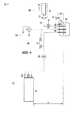
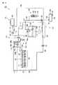
図1は、本発明の実施形態におけるインクジェットプリンタ1の構成を概略的に示す図である。以下の説明では、記録媒体の搬送方向をX方向、X方向と直交する記録媒体の幅方向をY方向、X方向及びY方向に直交する方向をZ方向(鉛直方向)と定義する。
インクジェットプリンタ1は、媒体供給部2と、搬送部3と、画像記録部4と、媒体収納部5と、これら構成部や後述するインク経路の各構成部を始めとしてプリンタ全体を制御する制御部6と、を有している。なお、インクジェットプリンタ1は、これら構成部以外にも、後述するインク経路、不図示の画像記録部移動機構、クリーニング部など、通常のプリンタが備えている構成部を有しているものとする。FIG. 1 is a diagram schematically showing the configuration of an
The
媒体供給部2は、記録媒体7を収納する媒体トレイ8と、ピックアップローラ9と、媒体ガイド10と、レジストローラ対11と、を有している。媒体トレイ8には、記録用紙、フィルムなどの記録媒体7が収納されている。ピックアップローラ9は、媒体トレイ8内の記録媒体7と当接して、その当接した記録媒体7を1枚ずつ取り出して搬送方向下流側の媒体ガイド10へと送り出す。媒体ガイド10は、かくして送り出された記録媒体7をレジストローラ対11へと案内する。レジストローラ対11は、記録媒体7の先端をレジストローラ対11のニップ部に当接させて、記録媒体7の搬送方向に対する傾きを補正してから、記録媒体7を搬送部3へと搬送する。 The
搬送部3は、媒体供給部2よりも搬送方向下流側に、画像記録部4と対向して配置されている。この搬送部3は、従動ローラ12と、テンションローラ13と、駆動ローラ14と、搬送ベルト15と、プラテン16と、吸引ファン17と、を有している。 The transport unit 3 is disposed opposite to the
搬送ベルト15は、例えば、帯状の無端ベルトであり、その表面に複数の孔が設けられている。この搬送ベルト15は、従動ローラ12、テンションローラ13及び駆動ローラ14によってテンションが掛けられた状態で保持されている。また、これら従動ローラ12、テンションローラ13及び駆動ローラ14は、不図示の搬送部フレームに回転可能に保持されている。なお、駆動ローラ14には、不図示のモータが接続されており、このモータの駆動により搬送ベルト15が所定の方向に回転する。 The conveyor belt 15 is, for example, a belt-like endless belt, and a plurality of holes are provided on the surface thereof. The conveyor belt 15 is held in a state where tension is applied by the driven roller 12, the tension roller 13, and the driving roller 14. Further, the driven roller 12, the tension roller 13, and the driving roller 14 are rotatably held by a conveyance unit frame (not shown). Note that a motor (not shown) is connected to the driving roller 14, and the conveyance belt 15 rotates in a predetermined direction by driving the motor.
プラテン16及び吸引ファン17は、搬送ベルト15の下方に、不図示の搬送部フレームによって保持されている。プラテン16は、少なくとも画像記録部4と対向する領域が平面となるように加工されており、また、この領域には、複数の孔が形成されている。吸引ファン17は、プラテン16の下方に配置されており、搬送ベルト15及びプラテン16に形成された複数の孔を通してエアを吸引する。これにより、レジストローラ対11から搬送された記録媒体7は、搬送ベルト15上に吸着され、所定の搬送速度で下流側の媒体収納部5へと搬送される。 The platen 16 and the suction fan 17 are held below the transport belt 15 by a transport unit frame (not shown). The platen 16 is processed so that at least a region facing the
画像記録部4は、搬送部3のプラテン16の上方に、このプラテン16に対向して配置されている。この画像記録部4は、例えば、各々がシアン、ブラック、マゼンタ、イエローの4色のインクを吐出する記録ヘッド18(18a、18b、18c、18d)と、記録ヘッド18を保持するヘッド保持部材19と、を有している。 The
記録ヘッド18は、記録媒体7の幅方向における画像記録が行われる領域と同等かそれ以上の幅を有している。記録ヘッド18は、複数のノズルが列をなして形成されたノズル面を有しており、これらノズルから記録媒体7にインクを吐出して画像を記録する。記録ヘッド18は、例えば、短尺なインクジェットヘッドを記録媒体7の幅方向(Y方向)に沿って互い違いに2列のライン状に(千鳥状に)配置したラインヘッドである。もちろん、記録ヘッド18は、1個の長尺なインクジェットヘッドであってもよいし、インクジェットヘッドが3列以上に配置された構成であってもよい。また、記録ヘッド18は、ラインタイプに限らず、記録媒体7上をY方向に走査しながら画像を記録するシリアルタイプであってもよい。 The
媒体収納部5は、搬送部3よりも搬送方向下流側に配置されている。この媒体収納部5は、媒体排出ローラ対20と、ストッカ21と、を有している。媒体排出ローラ対20は、画像記録部4により画像記録された記録媒体7を挟持して搬送部3から排出させる。ストッカ21は、媒体排出ローラ対20により排出された記録媒体7をストックする。 The
以上が、インクジェットプリンタ1の基本的な構成である。 The above is the basic configuration of the
[第1の実施形態]
図2は、第1の実施形態におけるインクジェットプリンタ1のインク経路30の構成を概略的に示す図である。図2には、1色のインク経路30のみを代表的に示しているが、インクジェットプリンタ1は、上述したように、複数の記録ヘッド18(18a、18b、18c、18d)を有しており、これら記録ヘッド18が複数色のインクをそれぞれ吐出して記録媒体7に画像を記録するために、色毎にインク経路30を有している。[First Embodiment]
FIG. 2 is a diagram schematically illustrating the configuration of the
インク経路30は、大別すると、ヘッド部31と、ヘッド部31にインクを供給するインク供給部32と、インク供給部32にインクを補充するインク補給部33と、を有している。このインク経路30は、画像記録時にインクを循環させることなく画像を記録する構成である。 The
まず、ヘッド部31について説明する。
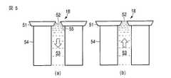
ヘッド部31は、記録ヘッド18を有している。この記録ヘッド18は、図5(a)並びに(b)に示すように、複数のノズル52が形成されたノズルプレート51及びこのノズルプレート51に接着された圧電素子54により簡略的に規定された圧力室53を有している。ヘッド部31は、外部から入力された信号に従ってこれらノズル52からインクを吐出することで記録媒体に画像を記録する。ヘッド部31(記録ヘッド18)には、図2に示すように、第1のインク通過口(供給ポート)31aと、第2のインク通過口(排出ポート)31bと、が設けられている。First, the head unit 31 will be described.
The head unit 31 has the
次に、インク供給部32について説明する。
インク供給部32は、吸引口と排出口とを備えたポンプ34と、ポンプ34の排出口とヘッド部31の第1のインク通過口31aとを接続している第1の経路35と、第1の経路35に配置されたフィルタ部36と、ヘッド部31の第2のインク通過口31bとポンプ34の吸引口を接続している第2の経路37(37a、37b)と、第2の経路37に配置され、第2の経路37を遮断可能な遮断弁38と、第2の経路37に配置され、ヘッド部31に供給するインクを貯留するインクタンク39と、を有している。第2の経路37は、ヘッド部31の第2のインク通過口31bから遮断弁38を介在してインクタンク39の回収口40に接続された経路37aと、インクタンク39の供給口41からポンプ34の吸引口に接続された経路37bと、を有している。図2では、第1の経路35が実線で、第2の経路37(37a、37b)が破線で示されている。Next, the
The
フィルタ部36は、ヘッド部31に供給されるインクに含まれる異物を除去し、ノズルの目詰まりなどに起因する記録不良をなくすために設けられている。例えば、インクを通過させるメッシュ状部材を備えており、そのメッシュ状部材の網目のサイズが、記録ヘッド18の各ノズル52を問題なく通過できる程度に小さい異物までも十分に除去可能なものを用いるとよい。本実施形態では、フィルタ部36は第1の経路35に配置されているが、第2の経路37に配置されてもよいし、さらには備えなくてもよい。 The
インクタンク39は、ヘッド部31(記録ヘッド18)よりも重力方向下方に配置されている。このインクタンク39は、第2の経路37aに接続された回収口40と、第2の経路37bに接続された供給口41と、大気開放口42と、後述の補給経路47に接続された補給口43と、を有している。また、インクタンク39内には不図示のインク量検出器が設けられている。大気開放口42は、大気開放弁44が配置された大気開放経路45に接続されており、大気開放弁44は、インクタンク39内部のインク液面よりも上方の空気層を大気に連通/遮断可能である。 The
本実施形態では、インクタンク39は第2の経路37に配置されているが、この配置に限らず、第1の経路35に配置されてもよい。なお、この場合には、インクタンク39の回収口40が供給口に、供給口41が回収口になる。 In the present embodiment, the
本発明では、ポンプ34の排出口からヘッド部31の第1のインク通過口31aまでの第1のインク流路の流路抵抗R1と、ヘッド部31の第2のインク通過口31bからポンプ34の吸引口までの第2のインク流路の流路抵抗R2との関係は、R1がR2よりも大きくなるように設定している(すなわち、R1>R2)。ここで、第1のインク流路の流路抵抗R1とは、第1の経路35の流路抵抗のみならず、第1の経路35に介在された部材(図2では、フィルタ部36)の寄与も含む第1のインク流路全体の流路抵抗値である。第2のインク流路の流路抵抗R2も同様である。 In the present invention, the flow path resistance R1 of the first ink flow path from the discharge port of the
次に、インク補給部33について説明する。
インク補給部33は、補給弁46を介在してインクタンク39の補給口43に接続された補給経路47と、インクが充填されているインクカートリッジ48と、インクカートリッジ48を着脱可能に保持するホルダ49と、インクカートリッジ48がホルダ49に装着されたとき、インクカートリッジ48を補給経路47に連通させるジョイント部50と、を有している。インクカートリッジ48は、インクタンク39よりも重力方向上方に設置されている。Next, the ink supply unit 33 will be described.
The ink supply unit 33 includes a
画像記録時には、遮断弁38及び大気開放弁44は開いている。このとき、記録ヘッド18のノズル52からインクが吐出されると、インク供給部32のインク量が減少する。インクは略非圧縮性であるため、インクタンク39内部のインクが、その減少分だけヘッド部31に補給される。また、吐出を続けてインクタンク39内部のインク量が減少したとき、不図示のインク量検出器がその減少を検出して、補給弁46が開放する。そして、インクカートリッジ48内のインクがインクタンク39に補給されて、所定量になると補給弁46が閉じられる。かくして、インク供給部32のインク量は、画像記録に十分なインク量に保持される。 At the time of image recording, the shut-off
ここで、記録ヘッド18がインクの吐出を行うためには、吐出に適した圧力(画像記録時ノズル圧)をノズル52にかける必要があるが、記録ヘッド18のノズルプレート51の面(ノズル面)の高さとインクタンク39内部のインク液面の高さとの水頭差Hによって生じるインクの水頭差圧によってノズル52に加わる圧力により、その機能が果されている。かくして、画像記録時には、インクタンク39内のインクがヘッド部31に供給されて、記録ヘッド18のノズル52からインクが吐出される。 Here, in order for the
記録ヘッド18がインクの吐出を行わない待機時は、ノズル52には、前述の水頭差Hによって生じるインクの水頭差圧によって、インクが重力方向上方に窪んだメニスカスが形成され、ノズルからのインク垂れを防ぐ。なお、前述の画像記録時ノズル圧と、待機時にノズルにかけるべき適正な圧力(待機時ノズル圧)とが異なる場合、第1又は第2の経路に新たに圧力生成機構を配置したり、ノズルにかかる水頭差圧を変更したりすることによって、ノズルにかかる負圧を調整してもよい。 During the standby time when the
次に、本実施形態におけるインク不吐出回復のためのクリーニング(以下では、メンテナンスと称する)動作について、図3乃至図5を参照して説明する。
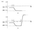
図3は、本実施形態におけるメンテナンス動作を示すフローチャートである。図4(a)並びに(b)は、メンテナンス動作時のノズル圧の時間変化を示すグラフである。図5(a)並びに(b)は、メンテナンス動作時の記録ヘッド18の内部を概略的に示す図である。Next, a cleaning operation for ink non-ejection recovery (hereinafter referred to as maintenance) in the present embodiment will be described with reference to FIGS.
FIG. 3 is a flowchart showing the maintenance operation in the present embodiment. FIGS. 4A and 4B are graphs showing temporal changes in nozzle pressure during a maintenance operation. FIGS. 5A and 5B are diagrams schematically showing the inside of the
メンテナンス動作の指示がなされると、一般的に知られたインクジェットプリンタと同様にして、図示しないクリーニング部等がメンテナンスのための位置に移動する。 When a maintenance operation is instructed, a cleaning unit (not shown) moves to a maintenance position in the same manner as a generally known inkjet printer.
本発明では、記録ヘッド18からインクを垂らさずに(排出せずに)メンテナンスを行う方法(循環洗浄)と、記録ヘッド18から不吐出原因の気泡又は異物等をインクと共に排出してメンテナンスを行う方法(加圧パージ)と、の2通りのメンテナンス方法を用意している。 In the present invention, maintenance is performed without circulating (not discharging) ink from the recording head 18 (circulation cleaning), and maintenance is performed by discharging bubbles or foreign matters that cause non-ejection from the
まず、メンテナンス方法の選択として、循環洗浄をするかどうかを判断する(ステップS1)。循環洗浄をする場合には、Yesに進む。
図4(a)は、循環洗浄時のノズル圧の時間変化を示している。
ステップS1においてYesに進んだ場合、続いて、大気開放弁44を閉じる(ステップS2)。これにより、第1及び第2の経路35、37は、密閉された閉じた経路を構成する。図4(a)に示すように、大気開放弁44を閉じた時間をT2とすると、このときのノズルにかかる圧力は待機時ノズル圧となっている。First, as a maintenance method selection, it is determined whether or not to perform circulation cleaning (step S1). When circulating cleaning is performed, the process proceeds to Yes.
FIG. 4A shows the change over time in the nozzle pressure during circulation cleaning.
If the process proceeds to Yes in step S1, then the
その後、第1の経路35に配置されたポンプ34が駆動される(ステップS3)。図4(a)には、ポンプ34の駆動が開始された時間をT3で示している。ポンプ34の駆動によって、第1の経路35は加圧され、逆に、第2の経路37は減圧される。従って、ポンプ34の排出口から第1の経路35、ヘッド部31及び第2の経路37を経由してポンプ34の吸引口にかけて圧力差が生じて、この閉じた経路中をインクが循環する。このとき、その圧力差がこの閉じた経路の各要素に案分される。 Thereafter, the
ここで、本発明では、先に述べたように、第1のインク流路の流路抵抗R1と第2のインク流路の流路抵抗R2との関係をR1>R2に設定しているため、ヘッド部31内の圧力は、ポンプ34の排出口からの加圧分よりもポンプ34の吸引口からの減圧分の方の寄与が大きくなる。換言すれば、流路抵抗の高い第1のインク流路にインクを送液するよりも、流路抵抗の低い第2のインク流路からインクを吸引するほうが容易いため、ヘッド部31の記録ヘッド18のノズル52内では、次第に、インクがポンプ34の排出口から送出されるよりもポンプ34の吸引口に吸引されるようになっていく。従って、ノズル圧は、図4(a)に示すように、ポンプ34の駆動開始時間T3以後、減少していく。すると、記録ヘッド18の圧力室53内のインクは、図5(a)に示す矢印方向に吸引されるので、圧力室53の壁にへばり付いている気泡55は、壁から剥がれてインク中を漂うようになる。 Here, in the present invention, as described above, the relationship between the flow path resistance R1 of the first ink flow path and the flow path resistance R2 of the second ink flow path is set to R1> R2. The pressure in the head portion 31 is more greatly contributed by the reduced pressure from the suction port of the
なお、本実施形態では、循環洗浄中にヘッド部31にかかる減圧によりノズルのメニスカスが破壊されないように、第1及び第2のインク流路の流路抵抗R1、R2の比を設定している。すなわち、ポンプ34の駆動により、ヘッド部31の記録ヘッド18の圧力室53内は、予め定めた下限圧力の手前まで減圧される。この時のノズル圧を循環時ノズルとする。 In the present embodiment, the ratio of the channel resistances R1 and R2 of the first and second ink channels is set so that the meniscus of the nozzle is not broken by the pressure applied to the head unit 31 during the circulation cleaning. . That is, by driving the
このように、大気開放弁44を閉じた後にポンプ34を駆動させて、閉じた経路中でインクを循環させることで、ヘッド部31や第1及び第2のインク流路中を漂う不吐出原因をフィルタ部36でキャッチして、インク吐出異常を防ぐことができる。 In this way, the
さらに、このとき、図5(a)に示すように、記録ヘッド18の圧力室53内が減圧されることにより、圧力室53の壁や隅にへばり付いた気泡や異物等が吸引されて剥がれやすくなるという効果を有する。
以上が循環洗浄(ステップS2、S3)の説明である。Further, at this time, as shown in FIG. 5A, the
The above is the explanation of the circulation cleaning (steps S2 and S3).
循環洗浄をしない場合には、ステップS1においてNoに進み、続いて、メンテナンス方法の選択として、加圧パージをするかどうかを判断する(ステップS4)。加圧パージをする場合には、Yesに進む。
図4(b)は、加圧パージ時のノズル圧の時間変化を示している。
ステップS4においてYesに進んだ場合、ステップS5、続いてステップS6に進む。ステップS5は上述のステップS2と、ステップS6は上述のステップS3と同じであるため、説明は省略する。If the circulation cleaning is not performed, the process proceeds to No in step S1, and then, as a maintenance method selection, it is determined whether to perform pressure purge (step S4). When the pressure purge is performed, the process proceeds to Yes.
FIG. 4B shows the change over time in the nozzle pressure during the pressure purge.
If the process proceeds to Yes in step S4, the process proceeds to step S5 and then to step S6. Step S5 is the same as step S2 described above, and step S6 is the same as step S3 described above.
加圧パージでは、ステップS6でポンプ34が駆動された後、ポンプ34が駆動されたまま、圧力室53内が予め定めた下限圧力の手前まで減圧されてノズル圧が循環時ノズル圧付近で略一定になるまで、所定時間Tの経過を待つ(ステップS7)。例えば、ポンプ34駆動後のノズル圧の時間変化が予めわかっていれば、ノズル圧が所望の略一定の値になるまでの所定時間Tをタイマで測定することができるし、あるいは、圧力センサにより圧力室内の圧力を測定して所定時間Tの経過を判断することもできる。 In the pressure purge, after the
そして、所定時間T経過後の時間T8で遮断弁38を閉じて(ステップS8)、第2の経路37のインクの流れを遮断する。すると、ポンプ34による減圧はヘッド部31に寄与しなくなり、ポンプ34による加圧のみがヘッド部31にかかることになる。従って、ヘッド部31にかかる圧力は、図4(b)に示すように、時間T8の後に急激に上昇し、負圧側から正圧側へと一気に変化する。すると、記録ヘッド18の圧力室53内のインクは、図5(b)に示す矢印方向に加圧されて、ノズル52から排出される。 Then, the
このように、ステップS5、S6によって記録ヘッド18の圧力室53内を減圧することにより圧力室53の壁面や隅から剥がれやすくなった気泡や異物は、ステップS8以後、圧力室53内が勢いよく加圧されることにより記録ヘッド18のノズル52から排出されて、不吐出が回復されることができる。
以上が加圧パージ(ステップS5〜S8)の説明である。As described above, bubbles and foreign matters that have been easily peeled off from the wall surface and corners of the
The above is the description of the pressure purge (steps S5 to S8).
ステップS3又はステップS8の後、適宜、ポンプ34を停止させた後、及びステップS4においてNoに進んだ場合には、メンテナンス動作を終了する。 After step S3 or step S8, after appropriately stopping the
本発明によれば、大気遮断された閉じた経路中でポンプの駆動によりインクを循環させる際、ポンプの排出側に接続された第1のインク流路の流路抵抗がポンプの吸引側に接続された第2のインク流路の流路抵抗値よりも大きいことにより、記録ヘッドのノズル圧が減少していき、記録ヘッド内に張り付いた気泡や異物を吸引して剥がすことができる。また、その後に第2のインク流路を遮断することにより、記録ヘッドのノズル圧を急激に高め、記録ヘッド内の気泡や異物等をノズルから排出させて、インク吐出異常を防ぐことができる。 According to the present invention, when ink is circulated by driving the pump in a closed path that is shut off from the atmosphere, the flow resistance of the first ink flow path connected to the discharge side of the pump is connected to the suction side of the pump. By being larger than the flow path resistance value of the second ink flow path, the nozzle pressure of the recording head decreases, and bubbles and foreign matters stuck in the recording head can be sucked and peeled off. Further, by subsequently blocking the second ink flow path, the nozzle pressure of the recording head is rapidly increased, and bubbles, foreign matters, and the like in the recording head are discharged from the nozzles, thereby preventing ink ejection abnormalities.
[第2の実施形態]
図6は、第2の実施形態におけるインクジェットプリンタ1のインク経路60の構成を概略的に示す図である。図6には、図2と同様に、1色のインク経路60のみを代表的に示している。[Second Embodiment]
FIG. 6 is a diagram schematically illustrating the configuration of the
インク経路60は、大別すると、ヘッド部61と、インク循環部62と、インク補給部63と、を有している。このインク経路60は、画像記録時にインク循環部62中でインクを循環させながら、記録ヘッドからインクを吐出して画像を記録する構成である。 The
まず、ヘッド部61について説明する。
ヘッド部61は、第1の実施形態のヘッド部31と同様に構成されており、外部から入力された信号に従ってノズルからインクを吐出することで記録媒体に画像を記録する。ヘッド部61には、第1のインク通過口61aと、第2のインク通過口61bと、が設けられている。First, the
The
次に、インク循環部62について説明をする。
インク循環部62は、吸引口と排出口とを備えたポンプ64と、ポンプ64の排出口とヘッド部61の第1のインク通過口61aとを接続している第1の経路65と、第1の経路65に配置された圧力生成機構66及びフィルタ部67と、ヘッド部61の第2のインク通過口61bとポンプ64の吸引口とを接続している第2の経路68(68a、68b)と、第2の経路68に配置された温度調整部69と、第2の経路68に配置され、第2の経路68を遮断可能な遮断弁70と、を有している。なお、図6に示す破線矢印は、インク循環部62をインクが流れるときの流れ方向を示している。すなわち、インク循環部62では、ポンプ64によって送液されたインクが第1の経路65を介してヘッド部61に供給される。そして、ヘッド部61で使用されなかったインクが第2の経路68を介してポンプ64へ帰還する。Next, the ink circulation unit 62 will be described.
The ink circulation unit 62 includes a
次に、インク循環部62の各構成部について説明する。
ポンプ64は、ヘッド部61にインクを送液すると共に、ヘッド部61で吐出されなかったインクを帰還させる。ポンプ64の能力は、第1の経路65からヘッド部61に供給するインク量が記録ヘッドのノズルから吐出されるインク量を上回るように設定されている。また、このポンプ64は、インク循環中、常に駆動されている。そのため、ポンプ64の揚水圧が脈動変化すると、インク循環部62を流れるインクの流量、及び記録ヘッドのノズルにかかる圧力が脈動変化する。従って、ノズル圧を安定させるためには、ポンプ64が無脈動ポンプであることが望ましい。Next, each component of the ink circulation unit 62 will be described.
The
また、流体であるインクは、温度が下がると粘度が上がることが知られている。従って、循環中にノズルにかかる圧力を温度によって変化させないために、ポンプ64は、温度によらず一定圧で送液するポンプであることが望ましい。 In addition, it is known that ink that is a fluid increases in viscosity as the temperature decreases. Therefore, in order not to change the pressure applied to the nozzles during the circulation according to the temperature, it is desirable that the
圧力生成機構66は、記録ヘッドが吐出を行わない場合(待機時)に、記録ヘッドのノズルにメニスカスが生成されるような圧力(待機時ノズル圧)をかけるように圧力を調整する。なお、圧力生成機構66は、第2の経路68に配置されてもよく、また第1の経路65及び第2の経路68の両方に配置されてもよい。 The pressure generating mechanism 66 adjusts the pressure so as to apply a pressure (standby nozzle pressure) that generates a meniscus to the nozzles of the recording head when the recording head does not discharge (standby). Note that the pressure generation mechanism 66 may be disposed in the
圧力生成機構66は、ノズルのメニスカスの形成のために適切な圧力を生成する構成であればよく、例えば、第1及び第2の経路65、68に弾性部を設けて、ポンプ64が停止した場合にノズルに対し背圧を生成するものであったり、第1の経路65に負圧生成機構を備え、待機時に第1の経路65を吸引してノズルにメニスカスが形成されるような負圧をかけるものであったりすることができる。 The pressure generation mechanism 66 may be configured to generate an appropriate pressure for forming the meniscus of the nozzle. For example, an elastic portion is provided in the first and
フィルタ部67は、第1の実施形態と同様に、インクを通過させるメッシュ状部材を備えており、記録ヘッドの各ノズルを問題なく通過できる程度に小さい異物までも十分に除去可能なサイズの網目となっている。なお、フィルタ部67は、後述のインク補給部63に配置されてもよい。 Similar to the first embodiment, the
このように、第1の経路65は、ポンプ64から供給されたインクをフィルタ部67によって異物を除去すると共に、ヘッド部61に供給している。 As described above, the first path 65 removes the foreign matter from the ink supplied from the
第2の経路68は、ヘッド部61の第2のインク通過口61bからインク補給部63への接続部71までの経路68aと、インク補給部63への接続部71からポンプ64の吸引口までの経路68bと、を有している。すなわち、第2の経路68は、ヘッド部61の第2のインク通過口61bとポンプ64の吸引口とを接続している。 The
温度調整部69は、インク循環部62を流れるインクの温度を画像記録に適した範囲となるように調整する。そのため、インク循環部62には、図示しない温度検出手段が設けられており、この温度検出手段によって検出されたインクの温度が適正な範囲より低い場合は、温度調整部69がインクを加熱し、また、温度検出手段によって検出されたインクの温度が適正な範囲より高い場合は、温度調整部69がインクを冷却する。なお、温度調整部69は、第1の経路65に配置されてもよい。 また、第2の経路68には、上述したように、インク補給部63と接続するための接続部71が設けられている。詳細は後述するが、ヘッド部61からインクが吐出され、インク循環部62内のインクが減少すると、インク補給部63との接続部71を介してインク補給部63からインク循環部62にインクが補給される。 The temperature adjustment unit 69 adjusts the temperature of the ink flowing through the ink circulation unit 62 to be in a range suitable for image recording. Therefore, the ink circulation unit 62 is provided with a temperature detection unit (not shown). When the temperature of the ink detected by the temperature detection unit is lower than the appropriate range, the temperature adjustment unit 69 heats the ink, When the temperature of the ink detected by the temperature detection unit is higher than the appropriate range, the temperature adjustment unit 69 cools the ink. Note that the temperature adjustment unit 69 may be disposed in the first path 65. Further, as described above, the
さらに 遮断弁70は、経路68aに配置されている。この遮断弁70は、記録動作中は開放されている。なお、遮断弁70は、経路68bに配置してもよい。 Further, the
このように、第2の経路68は、ヘッド部61で吐出されなかったインクを、温度調整部69でインクの温度を適正な温度にしてポンプ64へと帰還させる。 In this way, the
本実施形態においても、第1の実施形態と同様に、ポンプ64の排出口からヘッド部61の第1のインク通過口61aまでの第1のインク流路の流路抵抗R1と、ヘッド部61の第2のインク通過口31bからポンプ64の吸引口までの第2のインク流路の流路抵抗R2との関係は、R1がR2よりも大きくなるように設定している。 Also in the present embodiment, as in the first embodiment, the flow path resistance R1 of the first ink flow path from the discharge port of the
次に、インク補給部63について説明する。
インク補給部63は、第2の経路68の接続部71に接続された補給経路72と、この補給経路72に配置された補給弁73と、インクが充填されているインクカートリッジ74と、インクカートリッジ74を着脱可能に保持するホルダ75と、インクカートリッジ74を補給経路72に連通させるジョイント部76と、を有している。補給弁73は、後述するように、インク循環部62側とインク補給部63側との差圧に従って開閉するように構成されている。なお、本実施形態のインクカートリッジ74は、液体を収容する袋から成っていたり、装着時に大気開放されたりするような構成である。つまり、インクにかかる圧力が大気圧となっている。Next, the
The
また、インク補給部63には、ユーザへのインクカートリッジ交換を促すために、不図示の重量検知などの、インクカートリッジ74内のインク量を検出する手段が設けられてもよいし、吐出量からインク減少量を算出してもよい。 The
本実施形態では、画像記録時には、ポンプ64を駆動させることによって、第1の経路65が加圧され、逆に、第2の経路68は減圧される。従って、ポンプ64の排出口から第1の経路65、ヘッド部61及び第2の経路68を経由してポンプ64の吸引口にかけて圧力差が生じて、この閉じた経路中をインクが循環する。このとき、その圧力差が経路の各要素に案分されるが、本実施形態においても、第1の実施形態と同様に、第1のインク流路の流路抵抗R1が第2のインク流路の流路抵抗R2よりも大きいため、ヘッド部61の圧力は、ポンプ64の排出口からの加圧分よりもポンプ64の吸引口からの減圧分の寄与が大きくなり、従って、ヘッド部61は減圧されていく。本実施形態では、流路抵抗R1とR2の関係を、画像記録時のインク循環中にヘッド部61にかかる減圧によりノズルのメニスカスが破壊されない程度と設定している。 In the present embodiment, at the time of image recording, the first path 65 is pressurized by driving the
そして、ヘッド部61がインクを吐出すると、インク循環部62のインクが減少し、インク循環部62の圧力が低下する。従って、補給弁73にかかる差圧が増加して、これにより補給弁73が開いて、差圧に従ってインクカートリッジ74のインクがインク循環部62に補充される。すると、インク循環部62のインク量が増加し、インク循環部62の圧力が増加する。従って、インク補給部63にかかる差圧が低下して補給弁73が閉じる。このように、補給弁73は、差圧によってインク補給部63からインク循環部62へとインクを適宜補充する。 And when the
補給弁73の開閉により、ノズルにかかる圧力も変化するが、本実施形態においても、ノズルにかかる圧力がメニスカスを破壊しないように、インク補給部63が開く圧力を設定している。 Although the pressure applied to the nozzle also changes depending on the opening and closing of the replenishing
また、記録ヘッドが吐出を行わない場合は、ノズルからインクが垂れないように、前述した圧力生成機構66によって生成された負圧がノズルのメニスカスを形成している。 Further, when the recording head does not discharge, the negative pressure generated by the pressure generation mechanism 66 described above forms a meniscus of the nozzle so that ink does not drip from the nozzle.
本実施形態のような、画像記録時にインクを循環させて画像を記録するインクジェットプリンタにおいても、図3に示す第1の実施形態のフローチャートのステップS2、ステップS5を省略し、また、ステップS3、ステップS6のポンプ34をポンプ64と、ステップS8の遮断弁38を遮断弁70と読み替えて第1の実施形態と同様のメンテナンス動作を行うことにより、記録ヘッド内の気泡や異物等をなくし、インク吐出異常を防ぐことができる。 Even in an ink jet printer that records an image by circulating ink during image recording as in the present embodiment, steps S2 and S5 in the flowchart of the first embodiment shown in FIG. 3 are omitted, and step S3, By replacing the
[第2の実施形態の変形例]
本変形例では、遮断弁70の構成と、ポンプ64の駆動時の流量と、の2点が第2の実施形態と異なっている。[Modification of Second Embodiment]
In this modification, two points of the configuration of the
ポンプ64は、少なくとも2つの駆動モード、つまり、循環洗浄時の第1の駆動モード(Duty1)と、加圧パージ時の第2の駆動モード(Duty2)と、を有している。第1の駆動モードは、第1の流量でのインクの流れを含み、また、第2の駆動モードは、第1の流量よりも多い第2の流量でのインクの流れを含む。つまり、ポンプ64は、第1の駆動モードで駆動されたとき、経路中に第1の流量のインクの流れを与え、また、第2の駆動モードで駆動されたとき、経路中に第1の流量よりも多い第2の流量のインクの流れを与えるように設定されている。また、第2の流量でポンプ64を駆動させた場合、駆動させてから所定時間経過後に後述の遮断弁70が第2の流量のインクの流れにより閉じるように設定されている。なお、第1の駆動モードは、記録中に循環させるインクの流量よりも多い流量、且つメニスカスを破壊しない流量に設定されている。 The
図7(a)並びに(b)は、本変形例の遮断弁70の構造を示す図である。
この遮断弁70は、内壁から内側に延びた弁座78が設けられた弁箱77と、一端側が弁箱77に取り付けられ、他端側に弁部材79が取り付けられた弁ばね80と、を有している。この遮断弁70は、図7(a)に示すように、通常循環時(画像記録しながらインク循環しているとき、及びポンプ64の第1の駆動モード時)には、開いており、弁部材79の開口から弁室77内を通ってインクを流すが、図7(b)に示すように、遮断弁70にかかる圧力が一定量を超えたとき、つまり、本変形例においてポンプ64を第2の駆動モードで駆動させてから所定時間経過したとき、弁部材79が弁ばね80を圧縮して弁座78に当接し、閉じる。つまり、本変形例では、遮断弁70は、インク流量を調整しさえすれば遮断のための電気制御が不要な弁である。FIGS. 7A and 7B are views showing the structure of the
The shut-off
次に、本変形例におけるメンテナンス動作を、図8並びに図9を参照して説明する。
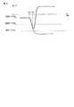
図8は、本変形例におけるメンテナンス動作を示すフローチャートである。図9は、加圧パージ時のノズル圧の時間変化を示すグラフである。Next, the maintenance operation in this modification will be described with reference to FIGS.
FIG. 8 is a flowchart showing a maintenance operation in this modification. FIG. 9 is a graph showing the change over time in nozzle pressure during pressure purge.
まず、メンテナンス方法の選択として、循環洗浄するかどうかを判断する(ステップS9)。循環洗浄をする場合には、Yesに進み、第1の経路65に配置されたポンプ64を第1の駆動モードで駆動させる(ステップS10)。この循環洗浄は、第1の実施形態の循環洗浄と同様であるので、説明は省略する。 First, as a maintenance method selection, it is determined whether or not to perform circulation cleaning (step S9). When circulating cleaning is performed, the process proceeds to Yes, and the
循環洗浄をしない場合には、ステップS9においてNoに進み、続いて、メンテナンス方法の選択として、加圧パージをするかどうかを判断する(ステップS11)。加圧パージをする場合には、Yesに進む。 When the circulation cleaning is not performed, the process proceeds to No in step S9, and subsequently, as a maintenance method selection, it is determined whether to perform pressure purge (step S11). When the pressure purge is performed, the process proceeds to Yes.
ステップS11においてYesに進んだ場合、第1の経路65に配置されたポンプ64を第2の駆動モードで駆動させる(ステップS12)。この第2の駆動モードでの駆動によって、第1の経路65は加圧され、逆に、第2の経路68は減圧される。従って、ポンプ64の排出口から第1の経路65、ヘッド部61及び第2の経路68を経由してポンプ64の吸引口にかけて圧力差が生じて、この閉じた経路中をインクが循環する。このとき、その圧力差がこの閉じた経路の各要素に案分される。 When the process proceeds to Yes in step S11, the
本変形例においても、第1のインク流路の流路抵抗R1と第2のインク流路の流路抵抗R2との関係をR1>R2に設定しているため、ヘッド部61内の圧力は、ポンプ64の排出口の加圧分よりもポンプ64の吸引口からの減圧分の方の寄与が大きくなる。このため、ヘッド部61は、図9に示すように、ポンプ64の駆動開始時間T12以後、減圧される。ここで、ポンプ64は、循環洗浄における第1の駆動モードよりも流量の大きい第2の駆動モードで駆動しているため、図9に示すように、循環洗浄における減圧量よりもさらに減圧される。従って、壁面や隅にへばり付いた気泡や異物はより剥がれやすくなる。 Also in this modification, since the relationship between the channel resistance R1 of the first ink channel and the channel resistance R2 of the second ink channel is set to R1> R2, the pressure in the
そして、遮断弁70にかかる圧力が一定量を超えたとき(図9に時間T70で示される)、弁部材79が弁ばね80を圧縮して弁座78に当接することにより遮断弁70が閉じ、第2の経路68が遮断される。すると、ポンプ64による減圧はヘッド部61に寄与しなくなり、ポンプ64による加圧のみがヘッド部61にかかることになる。従って、ヘッド部61にかかる圧力は、図9に示すように急激に上昇し、ステップS12で壁面や隅から剥がれやすくなった気泡や異物等が勢いよく加圧されることによりヘッド部61から排出され、不吐出が回復されることができる。
なお、遮断弁70は、ノズルに形成されたメニスカスが破壊される圧力(限界ノズル圧)に達する前に閉まるように設定されている。When the pressure applied to the
The
本変形例によれば、インク循環部の循環経路を遮断する弁を電気制御する必要をなくすことができる。また、パージ加圧時に循環洗浄時よりも大きなインク流量を与えることによって、第1の実施形態よりもノズルにかかる負圧量が大きくなるため、気泡や異物等をより剥がれやすくすることができる。 According to this modification, it is possible to eliminate the need to electrically control the valve that blocks the circulation path of the ink circulation unit. Also, by giving a larger ink flow rate during the purge pressurization than during the circulation cleaning, the amount of negative pressure applied to the nozzle becomes larger than in the first embodiment, so that bubbles, foreign matters, etc. can be more easily peeled off.
[第3の実施形態]
図10は、第3の実施形態におけるインクジェットプリンタ1のインク経路100の構成を概略的に示す図である。図10には、図2並びに図6と同様に、1色のインク経路100のみを代表的に示している。[Third Embodiment]
FIG. 10 is a diagram schematically illustrating the configuration of the
インク経路100は、大別すると、画像記録部101と、インク循環部102と、インク補給部103と、インク循環部102で不要となったインクやオーバーフローしたインクを収容する廃液タンク部104と、を有している。このインク経路100も、第2の実施形態と同様に、画像記録時にインク循環部102中でインクを循環させながら、画像記録部101により画像を記録する構成である。 The
画像記録部101は、第1及び第2の実施形態のヘッド部31、61と同様に構成されたヘッド部105と、ヘッド部105にインクを供給するインク供給器106と、ヘッド部105からインクを回収するインク回収器107と、を有している。 The
インク循環部102は、下側タンク108と、上側タンク109と、ポンプ110と、熱交換部111と、フィルタ部112と、遮断弁113と、を有している。ポンプ110の排出口から熱交換部111、フィルタ部112、上側タンク109、画像記録部101までが、この順に、第1の経路114によって接続されており、また、画像記録部101から遮断弁113、下側タンク108、ポンプ110の吸引口までが、この順に、第2の経路115によって接続されている。なお、図10の第1及び第2の経路114、115の矢印は、インク循環部102をインクが循環するときのインクの流れる方向を示している。つまり、インクは、下側タンク108からポンプ110、熱交換部111、フィルタ部112、上側タンク109、画像記録部101の順に流れ、下側タンク108へ帰還する。 The
次に、インク循環部102の各構成部について詳しく説明する。
上側タンク109は、画像記録部101よりも重力方向上方となるように配置されている。さらに詳細には、上側タンク109内のインク液面116がヘッド部105のノズルプレートの面117よりも重力方向上方となるように配置されている。Next, each component of the
The
上側タンク109には、インク入口ポート109aと、インク出口ポート109bと、大気ポート109cと、が設けられている。また、上側タンク109内には、インク液面116の位置を所定の高さに保つために、液面検出部118が設けられている。 The
インク入口ポート109aは、チューブ(第1の経路114)によってフィルタ部112に接続されており、フィルタ部112から流出したインクが上側タンク109内に流入する。なお、インク入口ポート109aの上側タンク109内の開口部は、流入したインクに気泡が混入しにくいように、上側タンク109内のインク液面116よりも鉛直方向(重力方向)に低い位置に設けられている。 The
インク出口ポート109bは、チューブ(第1の経路114)によってインク供給器106に接続されており、上側タンク109内のインクがインク供給器106に流入する。インク供給器106に流入したインクは、略均等に各ヘッド部105に分配される。インク供給器106を介してヘッド部105に流入するインク量は、ヘッド部105のノズルから吐出されるインク量を上回るよう設定されているため、ノズルから吐出されずにヘッド部105内に残ったインクは、インク回収器107に流れ込み、インク回収器107に接続されたチューブ(第2の経路115)を通って下側タンク108に流出する。 The
大気ポート109cは、チューブ119によって廃液タンク部104の後述するオーバーフロータンク120と接続されている。このチューブ119には、大気開放弁121が設けられている。オーバーフロータンク120は、常時、大気に晒された状態のため、大気開放弁121の開閉(開放/遮断)により上側タンク109内を大気開放、又は密閉させることができる。このため、上側タンク109内のインクは、大気開放弁121が開放されると、上側タンク109と画像記録部101との水頭差によってインク供給器106に流れる。 The
上側タンク109に配設されている液面検出部118は、フロート部材118aと、液面位置センサ118bと、磁石118cと、を有している。フロート部材118aは、上側タンク109内のインクの液面の高さに応じて上下に揺動する。フロート部材118aには、磁石118cが取り付けられている。液面位置センサ118bは、磁気センサからなり、フロート部材118aに取り付けられた磁石118cを検出することによって、フロート部材118aの位置、すなわちインクの液面の高さを検出する。なお、液面検出部118は、例えば、上側タンク109の壁面の一部を透明部材で構成し、例えば、反射型光センサで直接液面の位置を検出する構成であってもよい。 The liquid level detection unit 118 disposed in the
下側タンク108は、画像記録部101よりも重力方向下方となるように配置されている。さらに詳細には、下側タンク108内のインク液面122がヘッド部105のノズルプレートの面よりも重力方向下方となるように配置されている。 The
下側タンク108には、インク入口ポート108aと、インク補給ポート108bと、インク出口ポート108cと、大気ポート108dと、が設けられている。また、下側タンク108内には、インク液面122を所定の高さに保つために、液面検出部123が設けられている。液面検出部123は、液面検出部118と同様に構成されているため、その説明は省略する。 The
インク入口ポート108aは、チューブ(第2の経路115)によって画像記録部101のインク回収器107に接続されている。ヘッド部105で吐出されなかったインクは、インク回収器107で一旦回収されて、下側タンク108へと流れ落ちる。 The
インク補給ポート108bは、チューブ(補給経路130)によってインク補給部103と接続されている。インク循環部102のインク量が予め設定されたインク量よりも減ったとき、インク補給部103から下側タンク108にインクが補給される。 The
インク出口ポート108cは、チューブ(第2の経路115)によってポンプ110と接続されている。また、大気ポート108dは、チューブ124によって廃液タンク部104の後述するオーバーフロータンク120と接続されている。このチューブ124には、大気開放弁125が設けられている。また、大気ポート108dと大気開放弁125をつなぐチューブ124は分岐され、分岐側が圧力調整機構126に接続されている。オーバーフロータンク120は、常時、大気に晒された状態のため、大気開放弁125の開閉(開放/遮断)により下側タンク108内を大気開放、又は密閉させることができる。 The
圧力調整機構126は、チューブによって下側タンク108内の空気室と接続され、負圧を発生させるベローズ部127と、錘部128と、ベローズ昇降機構129と、を有している。 The
ベローズ部127は、大気ポート108dに接続されており、伸長することで下側タンク108内の空気層を負圧状態にする。
まず、大気開放弁125を開放し、下側タンク108内の空気層を開放した状態でベローズ昇降機構129によりベローズ部127及び錘部128を上昇させる。そして、ベローズ部127及び錘部128を所定の位置まで上昇させた後、大気開放弁125を閉じる。このように大気開放弁125を閉じると、下側タンク108の空気部分及びベローズ部127の内部は、連通しつつ外部とは閉じられた空間となる。この状態でベローズ部127を伸縮させると、この閉じられた空間の体積が増減する。つまり、ベローズ昇降機構129を降下させるとベローズ部127が錘部128の重さによって下方に引っ張られ、この閉じられた空間の体積が増加し、下側タンク108内の空気部には、錘部128に加わる重力と釣り合う大きさの負圧が発生する。The
First, the
下側タンク108の負圧状態は、チューブで連通するヘッド部105内にも所定の負圧をかける。この所定の負圧により、ノズルにインクのメニスカスを形成することができる。また、この所定の負圧は、インク循環にも寄与している。このように、圧力調整機構126は、記録ヘッドに負圧を与えてノズルにインクのメニスカスを形成し、正常な記録動作を可能としている。 In the negative pressure state of the
ポンプ110は、下側タンク108のインク出口ポート108cとチューブ(第2の経路115)で接続されており、下側タンク108内のインクを上側タンク109へ送液するために設けられている。本実施形態においても、インク循環部102におけるポンプ110の排出口と画像記録部101とをつなぐ第1の流路の流路抵抗R1と、画像記録部101とポンプ110の吸引口をつなぐ第2の流路の流路抵抗R2との関係は、R1がR2よりも大きくなるように設定されている。 The
本実施形態では、ポンプ110の送液能力は、インク回収器107から下側タンク108に流入してくるインク量よりも、多くのインクを上側タンク109へと送液可能に設計されている。これは、下側タンク108のオーバーフローを防止するためである。すなわち、通常の使用状態で下側タンク108に流入するインク流量よりもポンプ110で送液可能なインク流量を多くすることで、下側タンク108からインクが溢れないようにするためである。 In the present embodiment, the liquid feeding capability of the
また、本実施形態では、ポンプ110にインクの粘度によらず定量なインク量を送液可能なギアポンプを用いているが、これに限ることなく、前述したように下側タンク108に流入するインク量よりも多くのインクを送液できる能力があるポンプであればよい。ギアポンプ以外のポンプとしては、例えば、ダイヤフラムポンプ、ピストンポンプ、チューブポンプ、ロータリーポンプ、渦巻きポンプであってもよい。 In this embodiment, a gear pump capable of feeding a fixed amount of ink regardless of the viscosity of the ink is used as the
熱交換部111は、チューブ(第1の経路114)によってポンプ110と接続されており、ポンプ110によって汲み上げられたインクを所定の温度に維持するように調整している。この熱交換部111は、図示しないが、ヒートシンク部と、冷却ファンと、ヒータ部と、インク流路部と、を有している。 The
フィルタ部112は、ヘッド部105に供給されるインクに含まれる異物を除去し、ノズルの目詰まりなどに起因する記録不良をなくすために設けられている。フィルタ部112は、第1並びに第2の実施形態のフィルタ部36、67と同様に構成されている。 The
次に、インク補給部103について説明する。
インク補給部103は、下側タンク108に接続された補給経路130と、この補給経路130中に配置された補給弁131と、インクが充填されているインクカートリッジ132と、インクカートリッジ132の供給口132aを着脱可能に装着するためのジョイント部133と、を有している。インクカートリッジ132の供給口132aがジョイント部133に装着されると、インクカートリッジ132内のインクがインク循環部102に供給される。補給弁131は、その開閉により、インク循環部102へのインク供給を制御する。Next, the
The
次に、廃液タンク部104について説明する。
廃液タンク部104は、ポンプ110の下方に配置されており、オーバーフロータンク120と、タンクトレイ134と、廃液タンク135と、廃インク量検知部136と、タンク装着検知部137と、を有している。Next, the waste
The waste
オーバーフロータンク120は、トレイ状に形成されており、ポンプ110の下方に配置されている。このような配置により、オーバーフロータンク120は、ポンプ110が破損してインクが漏れ出したとしても、漏れ出したインクを全て受け、プリンタ内部を汚さない。さらに、オーバーフロータンク120は、上側タンク109及び下側タンク108と接続されている。従って、プリンタの異常により上側タンク109や下側タンク108からインクが溢れ出したとしても、溢れ出したインクをオーバーフロータンク120に収容することができる。 The
オーバーフロータンク120は、チューブ138によって廃液タンク135と接続されている。廃液タンク135は、タンクトレイ134上に配置され、タンクトレイ134に対して着脱可能となっている。タンクトレイ134には、廃液タンク135内に収容されたインク量を検知する廃インク量検知部136と、重量の検知や光学的な検知により廃液タンク135が装着されているか否かを検知するタンク装着検知部137と、が設けられている。そして、廃液タンク135内に所定量の廃液が溜まると、廃インク量検知部136が検知してユーザに交換を示唆するように報知する。 The
また、インク補給部103からは、インクカートリッジ132の交換時に外部に漏れ出たインクがチューブ139を介して廃液として廃液タンク135に送出される。
このように構成されたインク循環部102は、画像記録時は、大気開放弁121を開放し、上側タンク109内を大気開放状態にすると共に、大気開放弁125を閉じ、下側タンク108内の圧力を所定の負圧状態にする。これによって、ヘッド部105のノズルには、内側に球面状に凹んだメニスカスが形成され、正常な記録動作が可能となっている。The
The
また、待機時には、大気開放弁121を閉じ、上側タンク109内を大気に対して遮断すると共に、大気開放弁125を開放し、下側タンク108を大気開放状態とする。このとき、下側タンク108は、前述したようにヘッド部105より重力方向下方に配置されているため、ヘッド部105のノズルには水頭差によりメニスカスが形成されている。つまり、待機時において、ヘッド部105からインクが垂れ落ちない。 Further, at the time of standby, the
以上のように構成されたインク経路100では、画像記録時もインクを循環させながらメニスカスを保つことができる。
また、このようなインク経路100でも、第1並びに第2の実施形態と同様にメンテナンス動作を行うことができる。つまり、図3に示す第1の実施形態のフローチャートのステップS2、S5の大気開放弁44を大気開放弁121、125と、ステップS3、S6のポンプ34をポンプ110と、ステップS8の遮断弁38を遮断弁113と読み替えて第1の実施形態と同様のメンテナンス動作を行うことにより、ヘッド部105内の気泡や異物等をなくし、インク吐出異常を防ぐことができる。In the
Also in such an
以上、本発明の実施形態について説明したが、本発明は、上述の実施の形態に限定されるものではなく、本発明の要旨を逸脱しない範囲でさまざまな改良及び変更が可能である。 Although the embodiments of the present invention have been described above, the present invention is not limited to the above-described embodiments, and various improvements and modifications can be made without departing from the scope of the present invention.
1…インクジェットプリンタ、2…媒体供給部、3…搬送部、4…画像記録部、5…媒体収納部、6…制御部、7…記録媒体、8…媒体トレイ、9…ピックアップローラ、10…媒体ガイド、11…レジストローラ対、12…従動ローラ、13…テンションローラ、14…駆動ローラ、15…搬送ベルト、16…プラテン、17…吸引ファン、18…記録ヘッド、19…ヘッド保持部材、20…媒体排出ローラ対、21…ストッカ、30…インク経路、31…ヘッド部、32…インク供給部、33…インク補給部、34…ポンプ、35…第1の経路、36…フィルタ部、37…第2の経路、38…遮断弁、39…インクタンク、40…回収口、41…供給口、42…補給口、43…大気開放口、44…大気開放弁、45…大気開放経路、46…補給経路、47…補給弁、48…インクカートリッジ、49…ホルダ、50…ジョイント部、51…ノズル、52…ノズルプレート、52…圧力室、54…圧電素子。 DESCRIPTION OF
Claims (6)
Translated fromJapanese吸引口と排出口とを備えたポンプと、
前記ポンプの排出口と前記記録ヘッドの前記インク供給ポートとを接続している第1のインク流路と、
前記記録ヘッドの前記インク排出ポートと前記ポンプの吸引口とを接続している第2のインク流路と、
前記第2のインク流路中に配置され、インクの流れを遮断する遮断弁と、
前記記録ヘッドよりも重力方向下方に配置され、前記第1又は第2のインク流路中に配置されたインクタンクと、
前記インクタンク内を大気開放可能な大気開放弁と、
前記ポンプ、前記遮断弁及び前記大気開放弁の動作を制御する制御部と、
を具備し、
前記第1のインク流路の流路抵抗R1と第2のインク流路の流路抵抗R2との関係は、R1>R2であり、
前記制御部は、前記大気開放弁を閉じて前記ポンプを駆動させることにより、前記第1のインク流路から前記第2のインク流路へとインクを循環させて、前記圧力室内を予め定めた下限圧力の手前まで減圧した後、前記遮断弁を閉じて、前記圧力室内を加圧して前記記録ヘッドの複数のノズルを加圧パージすることを特徴とするインクジェットプリンタ。A plurality of nozzles formed in pressure chambers communicating with the ink supply port and the ink discharge port, respectively, and a recording head for recording an image by discharging ink from the nozzles;
A pump having a suction port and a discharge port;
A first ink flow path connecting the discharge port of the pump and the ink supply port of the recording head;
A second ink flow path connecting the ink discharge port of the recording head and the suction port of the pump;
A shut-off valve disposed in the second ink flow path for shutting off an ink flow;
An ink tank disposed below the recording head in the gravity direction and disposed in the first or second ink flow path;
An air release valve capable of opening the inside of the ink tank to the atmosphere;
A control unit for controlling operations of the pump, the shutoff valve, and the atmosphere release valve;
Comprising
The relationship between the channel resistance R1 of the first ink channel and the channel resistance R2 of the second ink channel is R1> R2.
The controller circulates ink from the first ink flow path to the second ink flow path by closing the atmosphere release valve and driving the pump, thereby predetermining the pressure chamber. An ink jet printer characterized in that after the pressure is reduced to a level before the lower limit pressure, the shutoff valve is closed, and the pressure chamber is pressurized to purge the plurality of nozzles of the recording head under pressure.
吸引口と排出口とを備えたポンプと、
前記ポンプの排出口と前記記録ヘッドの前記インク供給ポートとを接続している第1のインク流路と、
前記記録ヘッドの前記インク排出ポートと前記ポンプの吸引口とを接続している第2のインク流路と、
前記第2のインク流路中に配置され、インクの流れを遮断する遮断弁と、
前記ポンプの動作を制御する制御部と、
を具備し、
前記第1のインク流路の流路抵抗R1と第2のインク流路の流路抵抗R2との関係は、R1>R2であり、
前記制御部は、前記ポンプを駆動させることにより、前記第1のインク流路から前記第2のインク流路へとインクを循環させて、前記圧力室内を予め定めた下限圧力の手前まで減圧した後、前記遮断弁を閉じて、前記圧力室内を加圧して前記記録ヘッドの複数のノズルを加圧パージすることを特徴とするインクジェットプリンタ。A plurality of nozzles formed in pressure chambers communicating with the ink supply port and the ink discharge port, respectively, and a recording head for recording an image by discharging ink from the nozzles;
A pump having a suction port and a discharge port;
A first ink flow path connecting the discharge port of the pump and the ink supply port of the recording head;
A second ink flow path connecting the ink discharge port of the recording head and the suction port of the pump;
A shut-off valve disposed in the second ink flow path for shutting off an ink flow;
A control unit for controlling the operation of the pump;
Comprising
The relationship between the channel resistance R1 of the first ink channel and the channel resistance R2 of the second ink channel is R1> R2.
The controller drives the pump to circulate ink from the first ink flow path to the second ink flow path to reduce the pressure chamber to a level before a predetermined lower limit pressure. Thereafter, the shut-off valve is closed and the pressure chamber is pressurized to purge the plurality of nozzles of the recording head under pressure.
前記制御部は、前記ポンプを前記第2の駆動モードで駆動させ、
前記遮断弁は、前記ポンプが前記第2の駆動モードで駆動されてから所定時間経過後に、前記第2の流量のインクの流れにより閉じるように構成されていることを特徴とする請求項2に記載のインクジェットプリンタ。The pump has a first drive mode that includes an ink flow at a first flow rate and a second drive mode that has an ink flow at a second flow rate greater than the first flow rate. And
The control unit drives the pump in the second drive mode,
3. The shut-off valve is configured to close with a flow of ink at the second flow rate after a predetermined time has elapsed since the pump was driven in the second drive mode. The inkjet printer as described.
吸引口と排出口とを備えたポンプと、
前記ポンプの排出口と前記記録ヘッドの前記インク供給ポートとを接続している第1のインク流路と、
前記記録ヘッドの前記インク排出ポートと前記ポンプの吸引口とを接続している第2のインク流路と、
前記第2のインク流路中に配置され、インクの流れを遮断する遮断弁と、
前記記録ヘッドよりも重力方向下方に配置され、前記第1又は第2のインク流路中に配置されたインクタンクと、
前記インクタンク内を大気開放可能な大気開放弁と、
を具備するインクジェットプリンタのクリーニング方法において、
前記第1のインク流路の流路抵抗R1と第2のインク流路の流路抵抗R2との関係は、R1>R2であり、
前記大気開放弁を閉じることと、
前記大気開放弁が閉じた状態で前記ポンプを駆動させることにより、前記第1のインク流路から前記第2のインク流路へとインクを循環させて、前記圧力室内を予め定めた下限圧力の手前まで減圧させることと、
前記減圧の後、前記遮断弁を閉じて、前記圧力室内を加圧して前記記録ヘッドの複数のノズルを加圧パージすることを特徴とするインクジェットプリンタのクリーニング方法。A plurality of nozzles formed in pressure chambers communicating with the ink supply port and the ink discharge port, respectively, and a recording head for recording an image by discharging ink from the nozzles;
A pump having a suction port and a discharge port;
A first ink flow path connecting the discharge port of the pump and the ink supply port of the recording head;
A second ink flow path connecting the ink discharge port of the recording head and the suction port of the pump;
A shut-off valve disposed in the second ink flow path for shutting off an ink flow;
An ink tank disposed below the recording head in the gravity direction and disposed in the first or second ink flow path;
An air release valve capable of opening the inside of the ink tank to the atmosphere;
In an inkjet printer cleaning method comprising:
The relationship between the channel resistance R1 of the first ink channel and the channel resistance R2 of the second ink channel is R1> R2.
Closing the atmosphere release valve;
By driving the pump with the air release valve closed, ink is circulated from the first ink flow path to the second ink flow path, and the pressure chamber has a predetermined lower limit pressure. Reducing the pressure to the front,
After the depressurization, the shut-off valve is closed, the pressure chamber is pressurized, and the plurality of nozzles of the recording head are pressurized and purged.
吸引口と排出口とを備えたポンプと、
前記ポンプの排出口と前記記録ヘッドの前記インク供給ポートとを接続している第1のインク流路と、
前記記録ヘッドの前記インク排出ポートと前記ポンプの吸引口とを接続している第2のインク流路と、
前記第2のインク流路中に配置され、インクの流れを遮断する遮断弁と、
を具備するインクジェットプリンタにおいて、
前記第1のインク流路の流路抵抗R1と第2のインク流路の流路抵抗R2との関係は、R1>R2であり、
前記ポンプを駆動させることにより、前記第1のインク流路から前記第2のインク流路へとインクを循環させて、前記圧力室内を予め定めた下限圧力の手前まで減圧させることと、
前記減圧の後、前記遮断弁を閉じて、前記圧力室内を加圧して前記記録ヘッドの複数のノズルを加圧パージすることを特徴とするインクジェットプリンタのクリーニング方法。A plurality of nozzles formed in pressure chambers communicating with the ink supply port and the ink discharge port, respectively, and a recording head for recording an image by discharging ink from the nozzles;
A pump having a suction port and a discharge port;
A first ink flow path connecting the discharge port of the pump and the ink supply port of the recording head;
A second ink flow path connecting the ink discharge port of the recording head and the suction port of the pump;
A shut-off valve disposed in the second ink flow path for shutting off an ink flow;
In an inkjet printer comprising:
The relationship between the channel resistance R1 of the first ink channel and the channel resistance R2 of the second ink channel is R1> R2.
Driving the pump to circulate ink from the first ink flow path to the second ink flow path to reduce the pressure chamber to a level before a predetermined lower limit pressure;
After the depressurization, the shut-off valve is closed, the pressure chamber is pressurized, and the plurality of nozzles of the recording head are pressurized and purged.
前記ポンプは、前記第2の駆動モードで駆動され、
前記遮断弁は、前記ポンプが前記第2の駆動モードで駆動されてから所定時間経過後に、前記第2の流量のインクの流れにより閉じるように構成されていることを特徴とする請求項5に記載のインクジェットプリンタのクリーニング方法。The pump has a first drive mode that includes an ink flow at a first flow rate and a second drive mode that includes an ink flow at a second flow rate greater than the first flow rate. And
The pump is driven in the second drive mode;
6. The shut-off valve is configured to close with a flow of ink at the second flow rate after a predetermined time has elapsed since the pump was driven in the second drive mode. A method for cleaning the inkjet printer as described.
Priority Applications (1)
| Application Number | Priority Date | Filing Date | Title |
|---|---|---|---|
| JP2011054353AJP2012187862A (en) | 2011-03-11 | 2011-03-11 | Inkjet printer and method of cleaning the same |
Applications Claiming Priority (1)
| Application Number | Priority Date | Filing Date | Title |
|---|---|---|---|
| JP2011054353AJP2012187862A (en) | 2011-03-11 | 2011-03-11 | Inkjet printer and method of cleaning the same |
Publications (1)
| Publication Number | Publication Date |
|---|---|
| JP2012187862Atrue JP2012187862A (en) | 2012-10-04 |
Family
ID=47081542
Family Applications (1)
| Application Number | Title | Priority Date | Filing Date |
|---|---|---|---|
| JP2011054353AWithdrawnJP2012187862A (en) | 2011-03-11 | 2011-03-11 | Inkjet printer and method of cleaning the same |
Country Status (1)
| Country | Link |
|---|---|
| JP (1) | JP2012187862A (en) |
Cited By (9)
| Publication number | Priority date | Publication date | Assignee | Title |
|---|---|---|---|---|
| JP2014079895A (en)* | 2012-10-12 | 2014-05-08 | Seiko Epson Corp | Liquid jet apparatus |
| JP2014111334A (en)* | 2012-12-05 | 2014-06-19 | Fuji Xerox Co Ltd | Droplet discharge device |
| JP2014124912A (en)* | 2012-12-27 | 2014-07-07 | Fuji Xerox Co Ltd | Liquid supply device and image forming device |
| JP2015128849A (en)* | 2014-01-07 | 2015-07-16 | セイコーエプソン株式会社 | Liquid discharge device and method for detecting state of liquid supply passage |
| JP2016155316A (en)* | 2015-02-25 | 2016-09-01 | 理想科学工業株式会社 | Inkjet printing device |
| JP2017080892A (en)* | 2015-10-22 | 2017-05-18 | キヤノン株式会社 | Liquid discharge device |
| JP2018167556A (en)* | 2017-03-30 | 2018-11-01 | ブラザー工業株式会社 | Printer |
| JP2021133513A (en)* | 2020-02-21 | 2021-09-13 | 株式会社リコー | Liquid discharge device |
| CN115720551A (en)* | 2020-06-24 | 2023-02-28 | 柯尼卡美能达株式会社 | image forming device |
- 2011
- 2011-03-11JPJP2011054353Apatent/JP2012187862A/ennot_activeWithdrawn
Cited By (13)
| Publication number | Priority date | Publication date | Assignee | Title |
|---|---|---|---|---|
| JP2014079895A (en)* | 2012-10-12 | 2014-05-08 | Seiko Epson Corp | Liquid jet apparatus |
| JP2014111334A (en)* | 2012-12-05 | 2014-06-19 | Fuji Xerox Co Ltd | Droplet discharge device |
| JP2014124912A (en)* | 2012-12-27 | 2014-07-07 | Fuji Xerox Co Ltd | Liquid supply device and image forming device |
| JP2015128849A (en)* | 2014-01-07 | 2015-07-16 | セイコーエプソン株式会社 | Liquid discharge device and method for detecting state of liquid supply passage |
| USRE48686E1 (en) | 2015-02-25 | 2021-08-17 | Riso Kagaku Corporation | Ink-jet printer |
| JP2016155316A (en)* | 2015-02-25 | 2016-09-01 | 理想科学工業株式会社 | Inkjet printing device |
| JP2017080892A (en)* | 2015-10-22 | 2017-05-18 | キヤノン株式会社 | Liquid discharge device |
| US9751317B2 (en) | 2015-10-22 | 2017-09-05 | Canon Kabushiki Kaisha | Liquid ejection device |
| JP2018167556A (en)* | 2017-03-30 | 2018-11-01 | ブラザー工業株式会社 | Printer |
| US10569563B2 (en) | 2017-03-30 | 2020-02-25 | Brother Kogyo Kabushiki Kaisha | Printer |
| JP2021133513A (en)* | 2020-02-21 | 2021-09-13 | 株式会社リコー | Liquid discharge device |
| JP7380311B2 (en) | 2020-02-21 | 2023-11-15 | 株式会社リコー | liquid discharge device |
| CN115720551A (en)* | 2020-06-24 | 2023-02-28 | 柯尼卡美能达株式会社 | image forming device |
Similar Documents
| Publication | Publication Date | Title |
|---|---|---|
| JP2012187862A (en) | Inkjet printer and method of cleaning the same | |
| JP5350820B2 (en) | Inkjet printer and ink circulation method | |
| JP5555505B2 (en) | Inkjet printer | |
| US7934790B2 (en) | Image recording apparatus with maintenance unit | |
| JP6256692B2 (en) | Liquid ejecting apparatus and control method thereof | |
| US8303094B2 (en) | Liquid supply apparatus, image forming apparatus and liquid supply method | |
| JP5277506B2 (en) | Inkjet recording head, ink storage device | |
| CN109484026B (en) | Liquid ejection device and control method of liquid ejection device | |
| US10682864B2 (en) | Ink-jet image forming device | |
| JP2010105169A (en) | Ink filling method | |
| JP2008173816A (en) | Inkjet recorder | |
| JP5461337B2 (en) | Inkjet printer and ink circulation method thereof | |
| JP5276902B2 (en) | Inkjet printer and ink detection method thereof | |
| JP5624812B2 (en) | Image recording device | |
| WO2017099008A1 (en) | Inkjet recording apparatus and air bubble removal method | |
| JP4638085B2 (en) | Ink supply apparatus and inkjet recording apparatus | |
| JP2017193062A (en) | Liquid droplet discharge device and control method of the liquid droplet discharge device | |
| JP5376998B2 (en) | Ink circulation mechanism | |
| JP2009101668A (en) | Ink supply control method | |
| JP6897186B2 (en) | Inkjet recording device | |
| JP5361764B2 (en) | Inkjet printer and abnormality detection method thereof | |
| JP5309939B2 (en) | Liquid ejecting apparatus and image forming apparatus | |
| JP2011062858A (en) | Ink filling method and inkjet printer | |
| JP2019142207A (en) | Liquid ejection unit and device for ejecting liquid | |
| JP5486386B2 (en) | Inkjet printer |
Legal Events
| Date | Code | Title | Description |
|---|---|---|---|
| A300 | Withdrawal of application because of no request for examination | Free format text:JAPANESE INTERMEDIATE CODE: A300 Effective date:20140513 |