JP2012185847A - Constant flow regulator mechanism - Google Patents
Constant flow regulator mechanismDownload PDFInfo
- Publication number
- JP2012185847A JP2012185847AJP2012117320AJP2012117320AJP2012185847AJP 2012185847 AJP2012185847 AJP 2012185847AJP 2012117320 AJP2012117320 AJP 2012117320AJP 2012117320 AJP2012117320 AJP 2012117320AJP 2012185847 AJP2012185847 AJP 2012185847A
- Authority
- JP
- Japan
- Prior art keywords
- fluid
- partition
- constant flow
- flow regulator
- movable partition
- Prior art date
- Legal status (The legal status is an assumption and is not a legal conclusion. Google has not performed a legal analysis and makes no representation as to the accuracy of the status listed.)
- Pending
Links
- 230000007246mechanismEffects0.000titleclaimsabstractdescription105
- 239000012530fluidSubstances0.000claimsabstractdescription243
- 238000005192partitionMethods0.000claimsabstractdescription139
- 238000004891communicationMethods0.000claimsdescription16
- 239000000463materialSubstances0.000claimsdescription7
- 238000000034methodMethods0.000claimsdescription6
- 238000007599dischargingMethods0.000claims1
- 230000007423decreaseEffects0.000description12
- 239000013013elastic materialSubstances0.000description6
- 230000003068static effectEffects0.000description6
- 238000004519manufacturing processMethods0.000description4
- 238000005259measurementMethods0.000description4
- 229920000642polymerPolymers0.000description4
- 230000033228biological regulationEffects0.000description2
- 230000001419dependent effectEffects0.000description2
- 238000013461designMethods0.000description2
- 239000002184metalSubstances0.000description2
- 239000000203mixtureSubstances0.000description2
- 230000002093peripheral effectEffects0.000description2
- 239000004033plasticSubstances0.000description2
- 239000012858resilient materialSubstances0.000description2
- 238000012360testing methodMethods0.000description2
Images


Classifications
- F—MECHANICAL ENGINEERING; LIGHTING; HEATING; WEAPONS; BLASTING
- F16—ENGINEERING ELEMENTS AND UNITS; GENERAL MEASURES FOR PRODUCING AND MAINTAINING EFFECTIVE FUNCTIONING OF MACHINES OR INSTALLATIONS; THERMAL INSULATION IN GENERAL
- F16K—VALVES; TAPS; COCKS; ACTUATING-FLOATS; DEVICES FOR VENTING OR AERATING
- F16K17/00—Safety valves; Equalising valves, e.g. pressure relief valves
- F16K17/20—Excess-flow valves
- F16K17/34—Excess-flow valves in which the flow-energy of the flowing medium actuates the closing mechanism
- F—MECHANICAL ENGINEERING; LIGHTING; HEATING; WEAPONS; BLASTING
- F15—FLUID-PRESSURE ACTUATORS; HYDRAULICS OR PNEUMATICS IN GENERAL
- F15C—FLUID-CIRCUIT ELEMENTS PREDOMINANTLY USED FOR COMPUTING OR CONTROL PURPOSES
- F15C3/00—Circuit elements having moving parts
- F15C3/04—Circuit elements having moving parts using diaphragms
- F—MECHANICAL ENGINEERING; LIGHTING; HEATING; WEAPONS; BLASTING
- F16—ENGINEERING ELEMENTS AND UNITS; GENERAL MEASURES FOR PRODUCING AND MAINTAINING EFFECTIVE FUNCTIONING OF MACHINES OR INSTALLATIONS; THERMAL INSULATION IN GENERAL
- F16K—VALVES; TAPS; COCKS; ACTUATING-FLOATS; DEVICES FOR VENTING OR AERATING
- F16K31/00—Actuating devices; Operating means; Releasing devices
- F16K31/12—Actuating devices; Operating means; Releasing devices actuated by fluid
- F16K31/36—Actuating devices; Operating means; Releasing devices actuated by fluid in which fluid from the circuit is constantly supplied to the fluid motor
- F16K31/38—Actuating devices; Operating means; Releasing devices actuated by fluid in which fluid from the circuit is constantly supplied to the fluid motor in which the fluid works directly on both sides of the fluid motor, one side being connected by means of a restricted passage and the motor being actuated by operating a discharge from that side
- F16K31/385—Actuating devices; Operating means; Releasing devices actuated by fluid in which fluid from the circuit is constantly supplied to the fluid motor in which the fluid works directly on both sides of the fluid motor, one side being connected by means of a restricted passage and the motor being actuated by operating a discharge from that side the fluid acting on a diaphragm
- G—PHYSICS
- G05—CONTROLLING; REGULATING
- G05D—SYSTEMS FOR CONTROLLING OR REGULATING NON-ELECTRIC VARIABLES
- G05D7/00—Control of flow
- G05D7/01—Control of flow without auxiliary power
- G05D7/0106—Control of flow without auxiliary power the sensing element being a flexible member, e.g. bellows, diaphragm, capsule
- G05D7/0113—Control of flow without auxiliary power the sensing element being a flexible member, e.g. bellows, diaphragm, capsule the sensing element acting as a valve
- Y—GENERAL TAGGING OF NEW TECHNOLOGICAL DEVELOPMENTS; GENERAL TAGGING OF CROSS-SECTIONAL TECHNOLOGIES SPANNING OVER SEVERAL SECTIONS OF THE IPC; TECHNICAL SUBJECTS COVERED BY FORMER USPC CROSS-REFERENCE ART COLLECTIONS [XRACs] AND DIGESTS
- Y10—TECHNICAL SUBJECTS COVERED BY FORMER USPC
- Y10T—TECHNICAL SUBJECTS COVERED BY FORMER US CLASSIFICATION
- Y10T137/00—Fluid handling
- Y10T137/0318—Processes
- Y10T137/0396—Involving pressure control
- Y—GENERAL TAGGING OF NEW TECHNOLOGICAL DEVELOPMENTS; GENERAL TAGGING OF CROSS-SECTIONAL TECHNOLOGIES SPANNING OVER SEVERAL SECTIONS OF THE IPC; TECHNICAL SUBJECTS COVERED BY FORMER USPC CROSS-REFERENCE ART COLLECTIONS [XRACs] AND DIGESTS
- Y10—TECHNICAL SUBJECTS COVERED BY FORMER USPC
- Y10T—TECHNICAL SUBJECTS COVERED BY FORMER US CLASSIFICATION
- Y10T137/00—Fluid handling
- Y10T137/7722—Line condition change responsive valves
- Y10T137/7754—Line flow effect assisted
- Y—GENERAL TAGGING OF NEW TECHNOLOGICAL DEVELOPMENTS; GENERAL TAGGING OF CROSS-SECTIONAL TECHNOLOGIES SPANNING OVER SEVERAL SECTIONS OF THE IPC; TECHNICAL SUBJECTS COVERED BY FORMER USPC CROSS-REFERENCE ART COLLECTIONS [XRACs] AND DIGESTS
- Y10—TECHNICAL SUBJECTS COVERED BY FORMER USPC
- Y10T—TECHNICAL SUBJECTS COVERED BY FORMER US CLASSIFICATION
- Y10T137/00—Fluid handling
- Y10T137/8593—Systems
Landscapes
- Engineering & Computer Science (AREA)
- General Engineering & Computer Science (AREA)
- Mechanical Engineering (AREA)
- Physics & Mathematics (AREA)
- General Physics & Mathematics (AREA)
- Automation & Control Theory (AREA)
- Theoretical Computer Science (AREA)
- Fluid Mechanics (AREA)
- Control Of Fluid Pressure (AREA)
- Safety Valves (AREA)
- Pipe Accessories (AREA)
- Flow Control (AREA)
Abstract
Description
Translated fromJapanese本発明は、一般的には、可変の流体圧力が作用したとき、流体の一定の流れ、好ましくは気体又は気体混合物の流れを維持するための一定流れ調整器機構に関する。流体の流れは、ml/sで測定可能である。特に、創造性のある一定の流れ調整器機構は、少なくともある動作範囲内で、作用する流体圧力にかかわらず実質的に一定の流体流れを維持するように構成される。 The present invention generally relates to a constant flow regulator mechanism for maintaining a constant flow of fluid, preferably a gas or gas mixture, when a variable fluid pressure is applied. The fluid flow can be measured in ml / s. In particular, the creative constant flow regulator mechanism is configured to maintain a substantially constant fluid flow regardless of the applied fluid pressure, at least within an operating range.
以前に知られている流体流れ調整器機構は、ばね、ダイアフラム、バルブ、及び弁座のように、いくつかの異なった相互に作用する部分を有する比較的複雑な機構である。これらの機構は、高精度での製造を要する多くの部品が必要でありかつ高い組立コストのため、製造するのが比較的高価である。以前に知られている機構の他の問題は、信頼度及び耐久性に関する。 Previously known fluid flow regulator mechanisms are relatively complex mechanisms having several different interacting parts, such as springs, diaphragms, valves, and valve seats. These mechanisms require many parts that need to be manufactured with high precision and are relatively expensive to manufacture due to high assembly costs. Other problems with previously known mechanisms relate to reliability and durability.
米国特許3463182は、変形可能なダイアフラム42におけるオリフィス50を通して流体が流れる一定の圧力流れ調整器を開示する。増加圧力下で流体が入口管22に作用したとき、ダイアフラムと入口管の肩24との間でオリフィス51を形成するように、ダイアフラムは変形する。その後、流体は、開口30を通り逃れるため、入口管22、オリフィス51及びオリフィス50を通過可能である。しかしながら、この調整器は、一定の流体圧力を生成するために設計されており、一定の流体流れを生成するために用いることができない。 US Pat. No. 3,346,182 discloses a constant pressure flow regulator through which fluid flows through an orifice 50 in a deformable diaphragm 42. When fluid acts on the inlet tube 22 under increasing pressure, the diaphragm deforms to form an orifice 51 between the diaphragm and the shoulder 24 of the inlet tube. Thereafter, fluid escapes through the opening 30 and can pass through the inlet tube 22, the orifice 51 and the orifice 50. However, this regulator is designed to generate a constant fluid pressure and cannot be used to generate a constant fluid flow.
本発明は、上述した問題点を解決するためになされ、簡易で信頼でき正確な一定流れ調整器機構を提供することを目的とする。 The present invention has been made to solve the above-described problems, and an object thereof is to provide a simple, reliable and accurate constant flow regulator mechanism.
本発明は、一定流れ調整器機構により流体の流れを一定に維持するための簡単な機構に基づく。基本概念は、入ってくる流体用の入口管又は開口と流体が連通する、膨張可能な内部コンパートメントを使用することである。内部コンパートメントは、入口管に面し弾性力を受けている可動の仕切りにより設定される。可動仕切りのサイズは、流体から可動仕切りへの圧力が外側よりも内側で大きく仕切りを入口管側へ移動するように、入口管のサイズよりも著しく大きい。 The present invention is based on a simple mechanism for maintaining a constant fluid flow with a constant flow regulator mechanism. The basic concept is to use an inflatable internal compartment in fluid communication with an inlet tube or opening for incoming fluid. The internal compartment is set by a movable partition facing the inlet tube and receiving elastic force. The size of the movable partition is significantly larger than the size of the inlet tube so that the pressure from the fluid to the movable partition is larger on the inside than on the outside and moves the partition toward the inlet tube.
上述したサイズ差により、入口管及び内部コンパートメントの圧力が増加したとき、弾性力に逆らって仕切りが入口管側へ移動して内部コンパートメントは膨張する。その結果、増加した圧力のため仕切りが移動するとき、機構を通過する流体に関する仕切りと入口管との間の通過領域は、減少される。このように、たとえ流体圧力が上昇しても、機構を通過する流体流れは、実質的に一定に維持される。入口管にて流体に作用する圧力が減少したとき、その結果内部コンパートメントにて減じた流体圧力のため、仕切りが弾性力により元に戻るように移動したとき、内部コンパートメントは縮み、それにより、機構を通過する流体の流れを一定に維持するように通過領域が増加する。 When the pressure in the inlet pipe and the internal compartment increases due to the size difference described above, the partition moves toward the inlet pipe against the elastic force, and the internal compartment expands. As a result, when the partition moves due to increased pressure, the passage area between the partition and the inlet tube for the fluid passing through the mechanism is reduced. In this way, the fluid flow through the mechanism remains substantially constant even if the fluid pressure increases. When the pressure acting on the fluid in the inlet pipe decreases, as a result of the fluid pressure reduced in the internal compartment, when the partition moves back due to elastic force, the internal compartment shrinks, thereby the mechanism The passage area is increased so as to maintain a constant flow of fluid through the.
弾性力は、可動仕切りにおいて、又はその少なくとも一部において、ゴム又は他のポリマーのような弾力のある材料を用いることにより得ることができる。好ましくは、仕切りに作用する弾性力の特性は、通過領域が流体圧力の変化に最適に応答して変化するように選択される。弾性を有する仕切りの最適の弾力特性は、適切な材料、及び/又は、弾性部分の厚さの選択により得られることができる。仕切りの移動が流入流体の圧力の変化の二乗に比例するように弾性力の特性が選択された場合、満足な結果を得ることができる。例えば、流入流体の圧力が4倍に増したならば、仕切りと入口管との間の流体通路は、半分のサイズになるであろう。 The elastic force can be obtained by using a resilient material such as rubber or other polymer in the movable partition or at least in part thereof. Preferably, the characteristic of the elastic force acting on the partition is selected such that the passage region changes optimally in response to changes in fluid pressure. Optimal elastic properties of the elastic partition can be obtained by selection of suitable materials and / or thickness of the elastic part. Satisfactory results can be obtained if the elastic force characteristics are selected such that the movement of the partition is proportional to the square of the change in pressure of the incoming fluid. For example, if the pressure of the incoming fluid is increased by a factor of 4, the fluid passage between the partition and the inlet tube will be half the size.
一定の流れ調整器機構を出る流体の適した出口開口は設けることができるが、本発明はこの点で制限されていない。さらに、入口管と内部コンパートメントとの間の流体の連通は、入口管から入ってくる流体の近くにおける高圧領域に位置する、仕切りにおける開口により、又は、入口管と内部コンパートメントとの間の独立した流体接続導管により得ることができる。 A suitable exit opening for fluid exiting a constant flow regulator mechanism can be provided, but the invention is not limited in this respect. In addition, fluid communication between the inlet tube and the internal compartment can be achieved by an opening in the partition located in the high pressure region near the fluid coming from the inlet tube or independent between the inlet tube and the internal compartment. It can be obtained by a fluid connection conduit.
入ってくる媒体の圧力が低いとき、内部コンパートメントは容積を有する必要がないが、膨張可能であり、よって、入ってくる媒体の圧力が増したとき、容積を増加可能であることに注目すべきである。 It should be noted that when the pressure of the incoming medium is low, the internal compartment need not have a volume, but is expandable, so that the volume can be increased when the pressure of the incoming medium is increased. It is.
本発明の一つの態様に係る一定の流れ調整器機構は、請求項1にクレームされる。本発明の別の態様による流体の流れを一定に維持する方法は、請求項13でクレームされる。本発明の好ましい実施形態は、従属項にて規定されている。 A flow regulator mechanism according to one aspect of the present invention is claimed in
創造性のある一定の流れ調整器機構は、単に、ハウジングと、可動の仕切りを有する膨張可能な内部コンパートメントとにより作製可能であるので、製造が簡単である。さらに、機構を構成する部品は、必ずしも高価ではない。その結果、すべて安い機構となる。それにもかかわらず、本発明による機構は、信頼性があり、小数のかつ通常の部品の使用により高い耐久性を有する。 A creative constant flow regulator mechanism is simple to manufacture because it can be made simply by a housing and an inflatable internal compartment with a movable partition. Furthermore, the parts that make up the mechanism are not necessarily expensive. The result is a cheap mechanism. Nevertheless, the mechanism according to the invention is reliable and has a high durability due to the use of a small number of ordinary parts.
好ましい実施形態では、可動な仕切りの少なくとも一部は、ダイアフラムを備える。例えば、ダイアフラムは、平ら又はドーム型とすることができる。 In a preferred embodiment, at least a part of the movable partition comprises a diaphragm. For example, the diaphragm can be flat or dome shaped.
本発明の好ましい実施形態について、添付の図に示した例示により以下に説明する。 Preferred embodiments of the present invention will now be described by way of example shown in the accompanying drawings.
上述したように、膨張可能な内部コンパートメントが使用可能である。内部コンパートメントは、入口圧力が増加したとき、当該機構を通過する流体流れに関する通過領域を減じるように膨張する。一方、入口圧力が減少したとき、内部コンパートメントは縮み、よって通過領域が拡がり、よれにより一定の流体流れが維持される。 As mentioned above, an inflatable internal compartment can be used. The internal compartment expands to reduce the passage area for fluid flow through the mechanism as the inlet pressure increases. On the other hand, when the inlet pressure decreases, the internal compartment shrinks, thus expanding the passage area and maintaining a constant fluid flow.
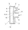
図1には、第1の実施形態に係る一定の流れ調整器機構が示されている。該機構は、互いに対向して配置された第1壁3及び第2壁4を有するチャンバー2を構成するハウジング1を備える。第1の実施形態において、側壁5は、第1及び第2の壁3,4とともに接合されている。しかしながら、側壁は、必ずしも必要ではない。例えば図4に示す第3の実施形態では、第1及び第2の壁3,4は、チャンバー2とともにハウジング1を構成するために、ともに接合されている。 FIG. 1 shows a constant flow regulator mechanism according to a first embodiment. The mechanism includes a
流入する流体流れ、即ち、一定に維持されるべき流れは、第1壁3に、例えば接続片とともに設けられる入口管又は開口6を通して入る。出て行く流体流れは、接続片とともに設けることができる少なくとも一つの出口開口7を通して機構から出る。この実施形態では、出口開口7は、側壁5に配置される。しかし、また、出口開口7は、図2又は図4にそれぞれ示される第2及び第3の実施形態のように、第1壁3に配置することもできる。又、以下に述べるように、内部コンパートメント9の外側で利用可能なスペースに依存して第2壁に出口開口を有することも考えられる。 The incoming fluid flow, i.e. the flow to be kept constant, enters the
図1に示される第1の実施形態によれば、内部コンパートメント9は、第2壁4とともに内部コンパートメントを構成するチャンバー2の内部に可動の仕切り8を配置することにより形成される。仕切り8は、ゴム又は他のポリマーのような弾性材料で作られている。内部コンパートメントは、好ましくは可動仕切り8に、入口管と内部コンパートメントとの間の流体の連通のために、可動仕切り8の中央部の好ましいいずれかの場所に開口10を設けている。入口管6もまた、第1壁3の中央部のいずれかの場所に配置され、よって可動仕切り8における開口10にほぼ対向する。しかしながら、開口10が入口管6にて流入する流体の高圧力領域付近に位置する限り、入口管6及び開口10は、一直線に配列される必要はない。入ってくる媒体の圧力が低いときに、内部コンパートメント9はいかなる容積も有する必要がないことも可能であるが、膨張可能であり、よって入ってくる媒体の圧力が増加したときには、ある容積を示すことができる。 According to the first embodiment shown in FIG. 1, the
上述したように、最初に、機構の部分の入口壁3及び内部コンパートメント9は、接続する必要はない。それらは、例えば互いに隣接し相対的に固定された位置に配置することができる。 As mentioned above, initially the
使用において、可動仕切り8は、入口管から離れる方向に基本的に作用する弾性力を受けている。一方、内部コンパートメント内の流体圧力は、入口管側への方向、つまり反対方向であり弾性力に抗する方向に仕切り8を移動するように作用する。好ましくは、第1の実施形態に示されるように、弾性力は、仕切り内に弾性材料を用いることにより得られる。入ってくる流体流れの圧力によって、内部コンパートメント9は、多かれ少なかれ「膨張」し、つまり可変の内部容積を有し、それにより、可動仕切りは、入ってくる流体圧力が変化したとき、第1壁3側へ、又は第1壁3から離れるように、それぞれ移動するであろう。 In use, the movable partition 8 receives an elastic force that basically acts in a direction away from the inlet tube. On the other hand, the fluid pressure in the internal compartment acts to move the partition 8 in the direction toward the inlet pipe, that is, in the opposite direction and against the elastic force. Preferably, as shown in the first embodiment, the elastic force is obtained by using an elastic material in the partition. Due to the pressure of the incoming fluid flow, the
好ましくは、仕切りにおける弾性材料の弾力の特性は、上記通過領域が可変流体圧力の変化に応答して最適に変化するように、例えば仕切りの移動変化が圧力変化の二乗に比例するように、選択される。それによって、入口管に入ってくる流体の圧力に上記弾性力を加えた力と、内部コンパートメント内の流体圧力からの反対方向への力との間のバランスが達成される。 Preferably, the elastic properties of the elastic material in the partition are selected such that the passage region changes optimally in response to changes in the variable fluid pressure, e.g. the change in movement of the partition is proportional to the square of the pressure change. Is done. Thereby, a balance is achieved between the force of the fluid pressure entering the inlet tube plus the elastic force and the force in the opposite direction from the fluid pressure in the internal compartment.
入口管6付近の可動仕切り8及び第1壁3と、開口10との間で、流体通路11は、可動仕切り8と第1壁3との間の距離に依存する断面積を有して存在する。可動仕切り8が第1壁3側へ又は第1壁3から離れて移動するとき、流体通路11の断面積は、それぞれ減少又は増加する。即ち、可動仕切り8と第1壁3との間の通路11は、減じられたり、広げられたりする。このように、通路11を通る流体流れ、及び一若しくは複数の出口開口7から排出される流れは、実質的に一定を維持するように、流体圧力の変化は、上記流体通路のサイズの変化により補償される。流体流れは、ml/sで測ることができる。 Between the movable partition 8 and the
好ましくは、一若しくは複数の出口開口7の断面積は、通路11にて全ての圧力降下が生じるように出口の流れを妨害しないため、流体通路11の断面積よりも実質的に大きい。 Preferably, the cross-sectional area of the one or
入口管又は開口6、一若しくは複数の出口開口7、開口10、弾性力の特性により決定されるような内部コンパートメント9の「膨張可能性」、及び可動仕切り8と入口管6との間の距離のある測定値を選択することにより、所望範囲、又は入ってくる流体の圧力の間隔にて、当該機構を通して一定の流体流れを提供するように動作する機構を設計することが可能になる。当業者は、それらの測定値に関するテストを行うことにより、所望の圧力間隔において一定の流体流れを提供する一定流れ調整器機構を得ることができる。 The inlet tube or
内部コンパートメント9は、例えば図2に示す実施形態を参照し、第2壁4、側壁5、及び可動仕切り8により形成することもできる。 The
好ましくは、可動仕切り8の少なくとも一部は、弾性力を提供する弾性ダイアフラム12で作製可能である。図1に示される第1の実施形態において、可動仕切り8は、ドーム型のダイアフラム12であり、図4に示される第3の実施形態において、可動仕切り8は、実質的に平らなダイアフラム12である。図2に示される第2の実施形態において、可動仕切り8は、開口10が形成されプラスチック又は金属のような硬質材料の板13と、ゴムのリングのような部分的なダイアフラム12とを備える。可動仕切り8は、流体漏れのない方法にてハウジング1内にはめられるべきである。板13及び、またハウジング1は、好ましくは円形状であるが、勿論、他の形状を採ることができる。 Preferably, at least a part of the movable partition 8 can be made of an
上述したように、流体流れ調節は、入口圧力からの力にダイアフラム(ダイアフラムが少なくとも部分的に使用された場合)の弾性からの力を加えた力と、内部コンパートメントの内側の流体圧力からの、反対方向における力との間のバランスの達成に基づいている。 As described above, fluid flow regulation is achieved by the force from the inlet pressure plus the force from the elasticity of the diaphragm (if the diaphragm is at least partially used) and the fluid pressure inside the internal compartment. Based on achieving a balance between forces in the opposite direction.
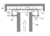
図5では、創造性のある一定の流れ調整器機構の第4の実施形態が図示され、これは、本発明の基本的なメカニズムをより詳細に以下に説明するために用いられる。 In FIG. 5, a fourth embodiment of a creative constant flow regulator mechanism is illustrated, which is used to explain the basic mechanism of the present invention in more detail below.
ハウジング500、及び弾性のダイアフラム502として作製された可動仕切りは、入ってくる流体用の入口管506と固定された関係にて配置される内部コンパートメント504を形成し、ダイアフラム502は、入口管506に面する。ダイアフラム502のサイズは、入口管506のサイズよりも著しく大きい。後者は、静的圧力と動的圧力との合計である流体圧力が入口管506に作用したとき、高圧力領域を構成する。ダイアフラム502は、入口管506の近くに、入ってくる流体と内部コンパートメント504との間の流体の連通を提供する開口508を有している。それにより、入口管506内の「A」での相対的に高い静的流体圧力が、開口508により、内部コンパートメント504内の「B」にも基本的に存在する。 A movable partition made as a
内部コンパートメント504内の流体圧力は、小さい矢印にて示すように、つまり入口管506の方向にて、弾性のダイアフラム502の内側に一様に作用する。入口管506とダイアフラム502との間に、上述の実施形態1〜3における通路11に関する記述のように、ダイアフラム502の移動により変化する断面積を有する流体通路510が形成される。入ってくる流体は、流体通路510を通り逃げ、入口管506の直後、図内の「C」にて、低圧力領域が基本的に形成されるように、通路510に沿って流体圧力は低下する。それによって、入口管506付近の内部コンパートメントの中央領域(高圧力領域)に比較して相対的に低い流体圧力は、内部コンパートメント504の外側であるその周縁領域(低圧力領域)でダイアフラム502に作用する。 The fluid pressure in the
入口管506に比較してダイアフラム502のより大きなサイズにより、流体圧力からのダイアフラム502への力は、外側よりも内側が大きく、ダイアフラム502を入口管506側へ移動させ、それにより流体通路510を減少させる。しかしながら、流体圧力は、ダイアフラム502に内在する弾性力によって平衡を保たれ、このことは、少なくともある作動圧力間隔内で、通路510が開いた状態に留まることができることを意味する。その結果、流体通路510は、流体圧力が変化したときに当該機構を通過する流体流れが実質的に一定を維持するように、入ってくる流体の圧力が増加したときには減少し、及びその逆にも動作する。ダイアフラム502の弾力の特性は、作動圧力範囲又は間隔内で最適な移動を提供するように、例えばダイアフラムの移動が圧力変化の二乗に比例するように、選択可能である。 Due to the larger size of the
図内で符号512の点線で示すように、ハウジング500は、流体が排出可能な出口開口514を含めて、出て行く流体を集めるための適宜な形態にて形成可能である。 As indicated by the dotted
図6では、創造性のある一定の流れ調整器機構の第5の実施形態が示され、これは、ダイアフラム502に開口508を有しない点で図5の第5実施形態とは異なる。その代りに、流体入口管602と内部コンパートメント604との間に、独立して流体接続導管600が配置される。内部コンパートメント604は、開口の無い弾性のダイアフラム606にて作製された可動の仕切りを有する。流体圧力は、内部コンパートメント604内で均一であるので、接続導管600は、内部コンパートメント604に、適切ないずれの位置にて接続可能である。 In FIG. 6, a fifth embodiment of a creative constant flow regulator mechanism is shown, which differs from the fifth embodiment of FIG. 5 in that it does not have an
よって、入口管602における流体圧力は、流体接続導管600の全体にわたる「D」に存在し、また、内部コンパートメント604内の「B」にも存在するであろう。流体圧力が変化したとき、一定の流体流れを得るために、弾性のダイアフラム606を移動させるためのメカニズムは、前の実施形態1〜4で述べたものと基本的に同じである。 Thus, the fluid pressure at the
入ってくる流体圧力が変化しなければ、流体接続導管600を通って流体は流れないので(その後全く少量の流体だけ)、入口管602における全圧の静止部分のみが導管600内に存在可能である。したがって、この実施形態では、流体入口管602は、好ましくは、可動仕切りに近接した狭い部分、及び管602からさらに離れ導管600への入口が位置する広い部分を有して形成される。このように、全圧の動的部分は、より遅い流れ速度のため、図内の「A1」の狭い部分にて有意であり、「A2」の広い部分においてそれほど重要ではない。したがって、全圧は、基本的に全圧がすべて内部コンパートメント604に伝えられるように、「A2」での静止部分によって支配されるであろう。それにより、圧力変化に対して機構をより応答させることになる。If the incoming fluid pressure does not change, no fluid will flow through the fluid connection conduit 600 (and then only a small amount of fluid), so that only a static portion of the total pressure in the
図7は、第6の実施形態による一定の流れ調整器機構の入口管700の正面図を示し、それは、図5及び図6の入口管506、602の端部、又は、図1〜図4に示す入口開口6のまさに内側に配置可能である。過剰な流体圧力により可動仕切りが入口管又は開口に接触して移動するならば、流体通路11又は510が完全に閉じられるという危険性を排除するため、複数の突出するノブ又はリブ702が、可動仕切りに面する入口管又は開口のまわりの端面に配置される。さらに、突出するノブ又はリブ702は、例えば、可動仕切りの材料の選択、及び/又はその弾性部分の厚みを組み合わせて、上記弾性力の特性にさらに影響を及ぼすために、任意に用いることができる。 FIG. 7 shows a front view of an
図8では、創造性のある一定の流れ調整器機構の第7の実施形態が示され、該第7実施形態は、弾性エレメントによりハウジング802に接続される、剛体の可動仕切り800を用いることにより、前の実施形態1〜6とは相違する。上記弾性エレメントは、仕切り800に作用する上述の弾性力を提供可能で、ここでは弾性ベローズ804等にて示されている。内部コンパートメント806は、仕切り800、ハウジング802、及びベローズ804によって形成される。内部コンパートメント806は、例えば、この図に示されるように仕切り800における開口808、又は図7に示されるように流体接続導管600により、入ってくる流体圧力と流体が連通している。流体圧力が変化したときに一定の流体流れを得るための可動仕切り800に関するメカニズムは、基本的に前の実施形態1〜5にて述べたものと同じである。ベローズ804の弾性特性は、上述したように、作動圧力範囲又は間隔内で仕切り800の最適な移動を提供するように、選択可能であることが注目されるべきである。 In FIG. 8, a seventh embodiment of a creative constant flow regulator mechanism is shown, which uses a rigid
図9では、創造性のある一定の流れ調整器機構の第8の実施形態が示され、剛体の可動仕切り902と、示されるように入口管906又は他の支持固定点(不図示)に取り付け可能な固定された支持板904との間に配置された弾性を有するベローズ900又はそのような物を使用することにより、図8に示す第7実施形態とは相違する。内部コンパートメント908は、仕切り902とハウジング910との間に形成される。弾性ベローズ900及び弾性ダイアフラム912がともに上述した仕切り800に作用する弾性力を提供するように、弾性のダイアフラム912も使用可能である。内部コンパートメント908は、例えば仕切り902における開口914によって、入ってくる流体圧力と流体が連通した状態にある。適切な流体出口開口916は、支持板904に配置可能である。流体圧力が変化したとき、一定の流体流れを得るために仕切り902を移動させるメカニズムは、基本的に前の実施形態1〜7に関して記載されたものと同じである。 In FIG. 9, an eighth embodiment of a creative constant flow regulator mechanism is shown, which can be attached to a rigid
図8及び図9にそれぞれ示されるベローズ804及びベローズ900は、上述の弾性力が得られる限り、適切ないずれの方法にて形成可能である。図9に示されるように、弾性ベローズ及び弾性ダイアフラムが組み合わされて使用されるとき、作動圧力範囲又は間隔内で一定の流体流れを生成するため仕切りの最適な移動を提供するように、それらの弾性特性は、選択可能であることに留意されるべきである。 The
本発明は、特定の例示的な実施形態を参照して記載されているが、記述は、一般的に単に発明概念を示すように意図したもので、本発明の範囲を制限するものとして受け取られるべきではない。「ハウジング」、「入口管」、及び「仕切り」のような、本発明を記述し規定するために用いられる用語は、広く解釈することができるということにまた留意すべきである。 Although the present invention has been described with reference to particular exemplary embodiments, the description is generally intended to be merely illustrative of the inventive concept and is taken as limiting the scope of the invention. Should not. It should also be noted that terms used to describe and define the present invention, such as “housing”, “inlet tube”, and “partition” can be broadly interpreted.
当業者は、添付の請求範囲にて規定される本発明から逸脱することなく、実施形態に示され記載された特徴の様々な適切な変更及び組み合わせを行うことができることを理解するであろう。 Those skilled in the art will appreciate that various suitable changes and combinations of the features shown and described in the embodiments can be made without departing from the invention as defined in the appended claims.
本発明は、一般的には、可変の流体圧力が作用したとき、流体の一定の流れ、好ましくは気体又は気体混合物の流れを維持するための一定流れ調整器機構に関する。流体の流れは、ml/sで測定可能である。特に、創造性のある一定の流れ調整器機構は、少なくともある動作範囲内で、作用する流体圧力にかかわらず実質的に一定の流体流れを維持するように構成される。 The present invention generally relates to a constant flow regulator mechanism for maintaining a constant flow of fluid, preferably a gas or gas mixture, when a variable fluid pressure is applied. The fluid flow can be measured in ml / s. In particular, the creative constant flow regulator mechanism is configured to maintain a substantially constant fluid flow regardless of the applied fluid pressure, at least within an operating range.
以前に知られている流体流れ調整器機構は、ばね、ダイアフラム、バルブ、及び弁座のように、いくつかの異なった相互に作用する部分を有する比較的複雑な機構である。これらの機構は、高精度での製造を要する多くの部品が必要でありかつ高い組立コストのため、製造するのが比較的高価である。以前に知られている機構の他の問題は、信頼度及び耐久性に関する。 Previously known fluid flow regulator mechanisms are relatively complex mechanisms having several different interacting parts, such as springs, diaphragms, valves, and valve seats. These mechanisms require many parts that need to be manufactured with high precision and are relatively expensive to manufacture due to high assembly costs. Other problems with previously known mechanisms relate to reliability and durability.
米国特許3463182は、変形可能なダイアフラム42におけるオリフィス50を通して流体が流れる一定の圧力流れ調整器を開示する。増加圧力下で流体が入口管22に作用したとき、ダイアフラムと入口管の肩24との間でオリフィス51を形成するように、ダイアフラムは変形する。その後、流体は、開口30を通り逃れるため、入口管22、オリフィス51及びオリフィス50を通過可能である。しかしながら、この調整器は、一定の流体圧力を生成するために設計されており、一定の流体流れを生成するために用いることができない。 US Pat. No. 3,346,182 discloses a constant pressure flow regulator through which fluid flows through an orifice 50 in a deformable diaphragm 42. When fluid acts on the inlet tube 22 under increasing pressure, the diaphragm deforms to form an orifice 51 between the diaphragm and the shoulder 24 of the inlet tube. Thereafter, fluid escapes through the opening 30 and can pass through the inlet tube 22, the orifice 51 and the orifice 50. However, this regulator is designed to generate a constant fluid pressure and cannot be used to generate a constant fluid flow.
本発明は、上述した問題点を解決するためになされ、簡易で信頼でき正確な一定流れ調整器機構を提供することを目的とする。 The present invention has been made to solve the above-described problems, and an object thereof is to provide a simple, reliable and accurate constant flow regulator mechanism.
本発明は、一定流れ調整器機構により流体の流れを一定に維持するための簡単な機構に基づく。基本概念は、入ってくる流体用の入口管又は開口と流体が連通する、膨張可能な内部コンパートメントを使用することである。内部コンパートメントは、入口管に面し弾性力を受けている可動の仕切りにより設定される。可動仕切りのサイズは、流体から可動仕切りへの圧力が外側よりも内側で大きく仕切りを入口管側へ移動するように、入口管のサイズよりも著しく大きい。 The present invention is based on a simple mechanism for maintaining a constant fluid flow with a constant flow regulator mechanism. The basic concept is to use an inflatable internal compartment in fluid communication with an inlet tube or opening for incoming fluid. The internal compartment is set by a movable partition facing the inlet tube and receiving elastic force. The size of the movable partition is significantly larger than the size of the inlet tube so that the pressure from the fluid to the movable partition is larger on the inside than on the outside and moves the partition toward the inlet tube.
上述したサイズ差により、入口管及び内部コンパートメントの圧力が増加したとき、弾性力に逆らって仕切りが入口管側へ移動して内部コンパートメントは膨張する。その結果、増加した圧力のため仕切りが移動するとき、機構を通過する流体に関する仕切りと入口管との間の通過領域は、減少される。このように、たとえ流体圧力が上昇しても、機構を通過する流体流れは、実質的に一定に維持される。入口管にて流体に作用する圧力が減少したとき、その結果内部コンパートメントにて減じた流体圧力のため、仕切りが弾性力により元に戻るように移動したとき、内部コンパートメントは縮み、それにより、機構を通過する流体の流れを一定に維持するように通過領域が増加する。 When the pressure in the inlet pipe and the internal compartment increases due to the size difference described above, the partition moves toward the inlet pipe against the elastic force, and the internal compartment expands. As a result, when the partition moves due to increased pressure, the passage area between the partition and the inlet tube for the fluid passing through the mechanism is reduced. In this way, the fluid flow through the mechanism remains substantially constant even if the fluid pressure increases. When the pressure acting on the fluid in the inlet pipe decreases, as a result of the fluid pressure reduced in the internal compartment, when the partition moves back due to elastic force, the internal compartment shrinks, thereby the mechanism The passage area is increased so as to maintain a constant flow of fluid through the.
弾性力は、可動仕切りにおいて、又はその少なくとも一部において、ゴム又は他のポリマーのような弾力のある材料を用いることにより得ることができる。好ましくは、仕切りに作用する弾性力の特性は、通過領域が流体圧力の変化に最適に応答して変化するように選択される。弾性を有する仕切りの最適の弾力特性は、適切な材料、及び/又は、弾性部分の厚さの選択により得られることができる。仕切りの移動が流入流体の圧力の変化の二乗に比例するように弾性力の特性が選択された場合、満足な結果を得ることができる。例えば、流入流体の圧力が4倍に増したならば、仕切りと入口管との間の流体通路は、半分のサイズになるであろう。 The elastic force can be obtained by using a resilient material such as rubber or other polymer in the movable partition or at least in part thereof. Preferably, the characteristic of the elastic force acting on the partition is selected such that the passage region changes optimally in response to changes in fluid pressure. Optimal elastic properties of the elastic partition can be obtained by selection of suitable materials and / or thickness of the elastic part. Satisfactory results can be obtained if the elastic force characteristics are selected such that the movement of the partition is proportional to the square of the change in pressure of the incoming fluid. For example, if the pressure of the incoming fluid is increased by a factor of 4, the fluid passage between the partition and the inlet tube will be half the size.
一定の流れ調整器機構を出る流体の適した出口開口は設けることができるが、本発明はこの点で制限されていない。さらに、入口管と内部コンパートメントとの間の流体の連通は、入口管から入ってくる流体の近くにおける高圧領域に位置する、仕切りにおける開口により、又は、入口管と内部コンパートメントとの間の独立した流体接続導管により得ることができる。 A suitable exit opening for fluid exiting a constant flow regulator mechanism can be provided, but the invention is not limited in this respect. In addition, fluid communication between the inlet tube and the internal compartment can be achieved by an opening in the partition located in the high pressure region near the fluid coming from the inlet tube or independent between the inlet tube and the internal compartment. It can be obtained by a fluid connection conduit.
入ってくる媒体の圧力が低いとき、内部コンパートメントは容積を有する必要がないが、膨張可能であり、よって、入ってくる媒体の圧力が増したとき、容積を増加可能であることに注目すべきである。 It should be noted that when the pressure of the incoming medium is low, the internal compartment need not have a volume, but is expandable, so that the volume can be increased when the pressure of the incoming medium is increased. It is.
本発明の一つの態様に係る一定の流れ調整器機構は、請求項6にクレームされる。本発明の別の態様による流体の流れを一定に維持する方法は、請求項1でクレームされる。本発明の好ましい実施形態は、従属項にて規定されている。 A flow regulator mechanism according to one aspect of the present invention is claimed in
創造性のある一定の流れ調整器機構は、単に、ハウジングと、可動の仕切りを有する膨張可能な内部コンパートメントとにより作製可能であるので、製造が簡単である。さらに、機構を構成する部品は、必ずしも高価ではない。その結果、すべて安い機構となる。それにもかかわらず、本発明による機構は、信頼性があり、小数のかつ通常の部品の使用により高い耐久性を有する。 A creative constant flow regulator mechanism is simple to manufacture because it can be made simply by a housing and an inflatable internal compartment with a movable partition. Furthermore, the parts that make up the mechanism are not necessarily expensive. The result is a cheap mechanism. Nevertheless, the mechanism according to the invention is reliable and has a high durability due to the use of a small number of ordinary parts.
好ましい実施形態では、可動な仕切りの少なくとも一部は、ダイアフラムを備える。例えば、ダイアフラムは、平ら又はドーム型とすることができる。 In a preferred embodiment, at least a part of the movable partition comprises a diaphragm. For example, the diaphragm can be flat or dome shaped.
本発明の好ましい実施形態について、添付の図に示した例示により以下に説明する。 Preferred embodiments of the present invention will now be described by way of example shown in the accompanying drawings.
上述したように、膨張可能な内部コンパートメントが使用可能である。内部コンパートメントは、入口圧力が増加したとき、当該機構を通過する流体流れに関する通過領域を減じるように膨張する。一方、入口圧力が減少したとき、内部コンパートメントは縮み、よって通過領域が拡がり、よれにより一定の流体流れが維持される。 As mentioned above, an inflatable internal compartment can be used. The internal compartment expands to reduce the passage area for fluid flow through the mechanism as the inlet pressure increases. On the other hand, when the inlet pressure decreases, the internal compartment shrinks, thus expanding the passage area and maintaining a constant fluid flow.
図1には、第1の実施形態に係る一定の流れ調整器機構が示されている。該機構は、互いに対向して配置された第1壁3及び第2壁4を有するチャンバー2を構成するハウジング1を備える。第1の実施形態において、側壁5は、第1及び第2の壁3,4とともに接合されている。しかしながら、側壁は、必ずしも必要ではない。例えば図4に示す第3の実施形態では、第1及び第2の壁3,4は、チャンバー2とともにハウジング1を構成するために、ともに接合されている。 FIG. 1 shows a constant flow regulator mechanism according to a first embodiment. The mechanism includes a
流入する流体流れ、即ち、一定に維持されるべき流れは、第1壁3に、例えば接続片とともに設けられる入口管又は開口6を通して入る。出て行く流体流れは、接続片とともに設けることができる少なくとも一つの出口開口7を通して機構から出る。この実施形態では、出口開口7は、側壁5に配置される。しかし、また、出口開口7は、図2又は図4にそれぞれ示される第2及び第3の実施形態のように、第1壁3に配置することもできる。又、以下に述べるように、内部コンパートメント9の外側で利用可能なスペースに依存して第2壁に出口開口を有することも考えられる。 The incoming fluid flow, i.e. the flow to be kept constant, enters the
図1に示される第1の実施形態によれば、内部コンパートメント9は、第2壁4とともに内部コンパートメントを構成するチャンバー2の内部に可動の仕切り8を配置することにより形成される。仕切り8は、ゴム又は他のポリマーのような弾性材料で作られている。内部コンパートメントは、好ましくは可動仕切り8に、入口管と内部コンパートメントとの間の流体の連通のために、可動仕切り8の中央部の好ましいいずれかの場所に開口10を設けている。入口管6もまた、第1壁3の中央部のいずれかの場所に配置され、よって可動仕切り8における開口10にほぼ対向する。しかしながら、開口10が入口管6にて流入する流体の高圧力領域付近に位置する限り、入口管6及び開口10は、一直線に配列される必要はない。入ってくる媒体の圧力が低いときに、内部コンパートメント9はいかなる容積も有する必要がないことも可能であるが、膨張可能であり、よって入ってくる媒体の圧力が増加したときには、ある容積を示すことができる。 According to the first embodiment shown in FIG. 1, the
上述したように、最初に、機構の部分の入口壁3及び内部コンパートメント9は、接続する必要はない。それらは、例えば互いに隣接し相対的に固定された位置に配置することができる。 As mentioned above, initially the
使用において、可動仕切り8は、入口管から離れる方向に基本的に作用する弾性力を受けている。一方、内部コンパートメント内の流体圧力は、入口管側への方向、つまり反対方向であり弾性力に抗する方向に仕切り8を移動するように作用する。好ましくは、第1の実施形態に示されるように、弾性力は、仕切り内に弾性材料を用いることにより得られる。入ってくる流体流れの圧力によって、内部コンパートメント9は、多かれ少なかれ「膨張」し、つまり可変の内部容積を有し、それにより、可動仕切りは、入ってくる流体圧力が変化したとき、第1壁3側へ、又は第1壁3から離れるように、それぞれ移動するであろう。 In use, the movable partition 8 receives an elastic force that basically acts in a direction away from the inlet tube. On the other hand, the fluid pressure in the internal compartment acts to move the partition 8 in the direction toward the inlet pipe, that is, in the opposite direction and against the elastic force. Preferably, as shown in the first embodiment, the elastic force is obtained by using an elastic material in the partition. Due to the pressure of the incoming fluid flow, the
好ましくは、仕切りにおける弾性材料の弾力の特性は、上記通過領域が可変流体圧力の変化に応答して最適に変化するように、例えば仕切りの移動変化が圧力変化の二乗に比例するように、選択される。それによって、入口管に入ってくる流体の圧力に上記弾性力を加えた力と、内部コンパートメント内の流体圧力からの反対方向への力との間のバランスが達成される。 Preferably, the elastic properties of the elastic material in the partition are selected such that the passage region changes optimally in response to changes in the variable fluid pressure, e.g. the change in movement of the partition is proportional to the square of the pressure change. Is done. Thereby, a balance is achieved between the force of the fluid pressure entering the inlet tube plus the elastic force and the force in the opposite direction from the fluid pressure in the internal compartment.
入口管6付近の可動仕切り8及び第1壁3と、開口10との間で、流体通路11は、可動仕切り8と第1壁3との間の距離に依存する断面積を有して存在する。可動仕切り8が第1壁3側へ又は第1壁3から離れて移動するとき、流体通路11の断面積は、それぞれ減少又は増加する。即ち、可動仕切り8と第1壁3との間の通路11は、減じられたり、広げられたりする。このように、通路11を通る流体流れ、及び一若しくは複数の出口開口7から排出される流れは、実質的に一定を維持するように、流体圧力の変化は、上記流体通路のサイズの変化により補償される。流体流れは、ml/sで測ることができる。 Between the movable partition 8 and the
好ましくは、一若しくは複数の出口開口7の断面積は、通路11にて全ての圧力降下が生じるように出口の流れを妨害しないため、流体通路11の断面積よりも実質的に大きい。 Preferably, the cross-sectional area of the one or
入口管又は開口6、一若しくは複数の出口開口7、開口10、弾性力の特性により決定されるような内部コンパートメント9の「膨張可能性」、及び可動仕切り8と入口管6との間の距離のある測定値を選択することにより、所望範囲、又は入ってくる流体の圧力の間隔にて、当該機構を通して一定の流体流れを提供するように動作する機構を設計することが可能になる。当業者は、それらの測定値に関するテストを行うことにより、所望の圧力間隔において一定の流体流れを提供する一定流れ調整器機構を得ることができる。 The inlet tube or
内部コンパートメント9は、例えば図2に示す実施形態を参照し、第2壁4、側壁5、及び可動仕切り8により形成することもできる。 The
好ましくは、可動仕切り8の少なくとも一部は、弾性力を提供する弾性ダイアフラム12で作製可能である。図1に示される第1の実施形態において、可動仕切り8は、ドーム型のダイアフラム12であり、図4に示される第3の実施形態において、可動仕切り8は、実質的に平らなダイアフラム12である。図2に示される第2の実施形態において、可動仕切り8は、開口10が形成されプラスチック又は金属のような硬質材料の板13と、ゴムのリングのような部分的なダイアフラム12とを備える。可動仕切り8は、流体漏れのない方法にてハウジング1内にはめられるべきである。板13及び、またハウジング1は、好ましくは円形状であるが、勿論、他の形状を採ることができる。 Preferably, at least a part of the movable partition 8 can be made of an
上述したように、流体流れ調節は、入口圧力からの力にダイアフラム(ダイアフラムが少なくとも部分的に使用された場合)の弾性からの力を加えた力と、内部コンパートメントの内側の流体圧力からの、反対方向における力との間のバランスの達成に基づいている。 As described above, fluid flow regulation is achieved by the force from the inlet pressure plus the force from the elasticity of the diaphragm (if the diaphragm is at least partially used) and the fluid pressure inside the internal compartment. Based on achieving a balance between forces in the opposite direction.
図5では、創造性のある一定の流れ調整器機構の第4の実施形態が図示され、これは、本発明の基本的なメカニズムをより詳細に以下に説明するために用いられる。 In FIG. 5, a fourth embodiment of a creative constant flow regulator mechanism is illustrated, which is used to explain the basic mechanism of the present invention in more detail below.
ハウジング500、及び弾性のダイアフラム502として作製された可動仕切りは、入ってくる流体用の入口管506と固定された関係にて配置される内部コンパートメント504を形成し、ダイアフラム502は、入口管506に面する。ダイアフラム502のサイズは、入口管506のサイズよりも著しく大きい。後者は、静的圧力と動的圧力との合計である流体圧力が入口管506に作用したとき、高圧力領域を構成する。ダイアフラム502は、入口管506の近くに、入ってくる流体と内部コンパートメント504との間の流体の連通を提供する開口508を有している。それにより、入口管506内の「A」での相対的に高い静的流体圧力が、開口508により、内部コンパートメント504内の「B」にも基本的に存在する。 A movable partition made as a
内部コンパートメント504内の流体圧力は、小さい矢印にて示すように、つまり入口管506の方向にて、弾性のダイアフラム502の内側に一様に作用する。入口管506とダイアフラム502との間に、上述の実施形態1〜3における通路11に関する記述のように、ダイアフラム502の移動により変化する断面積を有する流体通路510が形成される。入ってくる流体は、流体通路510を通り逃げ、入口管506の直後、図内の「C」にて、低圧力領域が基本的に形成されるように、通路510に沿って流体圧力は低下する。それによって、入口管506付近の内部コンパートメントの中央領域(高圧力領域)に比較して相対的に低い流体圧力は、内部コンパートメント504の外側であるその周縁領域(低圧力領域)でダイアフラム502に作用する。 The fluid pressure in the
入口管506に比較してダイアフラム502のより大きなサイズにより、流体圧力からのダイアフラム502への力は、外側よりも内側が大きく、ダイアフラム502を入口管506側へ移動させ、それにより流体通路510を減少させる。しかしながら、流体圧力は、ダイアフラム502に内在する弾性力によって平衡を保たれ、このことは、少なくともある作動圧力間隔内で、通路510が開いた状態に留まることができることを意味する。その結果、流体通路510は、流体圧力が変化したときに当該機構を通過する流体流れが実質的に一定を維持するように、入ってくる流体の圧力が増加したときには減少し、及びその逆にも動作する。ダイアフラム502の弾力の特性は、作動圧力範囲又は間隔内で最適な移動を提供するように、例えばダイアフラムの移動が圧力変化の二乗に比例するように、選択可能である。 Due to the larger size of the
図内で符号512の点線で示すように、ハウジング500は、流体が排出可能な出口開口514を含めて、出て行く流体を集めるための適宜な形態にて形成可能である。 As indicated by the dotted
図6では、創造性のある一定の流れ調整器機構の第5の実施形態が示され、これは、ダイアフラム502に開口508を有しない点で図5の第5実施形態とは異なる。その代りに、流体入口管602と内部コンパートメント604との間に、独立して流体接続導管600が配置される。内部コンパートメント604は、開口の無い弾性のダイアフラム606にて作製された可動の仕切りを有する。流体圧力は、内部コンパートメント604内で均一であるので、接続導管600は、内部コンパートメント604に、適切ないずれの位置にて接続可能である。 In FIG. 6, a fifth embodiment of a creative constant flow regulator mechanism is shown, which differs from the fifth embodiment of FIG. 5 in that it does not have an
よって、入口管602における流体圧力は、流体接続導管600の全体にわたる「D」に存在し、また、内部コンパートメント604内の「B」にも存在するであろう。流体圧力が変化したとき、一定の流体流れを得るために、弾性のダイアフラム606を移動させるためのメカニズムは、前の実施形態1〜4で述べたものと基本的に同じである。 Thus, the fluid pressure at the
入ってくる流体圧力が変化しなければ、流体接続導管600を通って流体は流れないので(その後全く少量の流体だけ)、入口管602における全圧の静止部分のみが導管600内に存在可能である。したがって、この実施形態では、流体入口管602は、好ましくは、可動仕切りに近接した狭い部分、及び管602からさらに離れ導管600への入口が位置する広い部分を有して形成される。このように、全圧の動的部分は、より遅い流れ速度のため、図内の「A1」の狭い部分にて有意であり、「A2」の広い部分においてそれほど重要ではない。したがって、全圧は、基本的に全圧がすべて内部コンパートメント604に伝えられるように、「A2」での静止部分によって支配されるであろう。それにより、圧力変化に対して機構をより応答させることになる。 If the incoming fluid pressure does not change, no fluid will flow through the fluid connection conduit 600 (and then only a small amount of fluid), so that only a static portion of the total pressure in the
図7は、第6の実施形態による一定の流れ調整器機構の入口管700の正面図を示し、それは、図5及び図6の入口管506、602の端部、又は、図1〜図4に示す入口開口6のまさに内側に配置可能である。過剰な流体圧力により可動仕切りが入口管又は開口に接触して移動するならば、流体通路11又は510が完全に閉じられるという危険性を排除するため、複数の突出するノブ又はリブ702が、可動仕切りに面する入口管又は開口のまわりの端面に配置される。さらに、突出するノブ又はリブ702は、例えば、可動仕切りの材料の選択、及び/又はその弾性部分の厚みを組み合わせて、上記弾性力の特性にさらに影響を及ぼすために、任意に用いることができる。 FIG. 7 shows a front view of an
図8では、創造性のある一定の流れ調整器機構の第7の実施形態が示され、該第7実施形態は、弾性エレメントによりハウジング802に接続される、剛体の可動仕切り800を用いることにより、前の実施形態1〜6とは相違する。上記弾性エレメントは、仕切り800に作用する上述の弾性力を提供可能で、ここでは弾性ベローズ804等にて示されている。内部コンパートメント806は、仕切り800、ハウジング802、及びベローズ804によって形成される。内部コンパートメント806は、例えば、この図に示されるように仕切り800における開口808、又は図7に示されるように流体接続導管600により、入ってくる流体圧力と流体が連通している。流体圧力が変化したときに一定の流体流れを得るための可動仕切り800に関するメカニズムは、基本的に前の実施形態1〜5にて述べたものと同じである。ベローズ804の弾性特性は、上述したように、作動圧力範囲又は間隔内で仕切り800の最適な移動を提供するように、選択可能であることが注目されるべきである。 In FIG. 8, a seventh embodiment of a creative constant flow regulator mechanism is shown, which uses a rigid
図9では、創造性のある一定の流れ調整器機構の第8の実施形態が示され、剛体の可動仕切り902と、示されるように入口管906又は他の支持固定点(不図示)に取り付け可能な固定された支持板904との間に配置された弾性を有するベローズ900又はそのような物を使用することにより、図8に示す第7実施形態とは相違する。内部コンパートメント908は、仕切り902とハウジング910との間に形成される。弾性ベローズ900及び弾性ダイアフラム912がともに上述した仕切り800に作用する弾性力を提供するように、弾性のダイアフラム912も使用可能である。内部コンパートメント908は、例えば仕切り902における開口914によって、入ってくる流体圧力と流体が連通した状態にある。適切な流体出口開口916は、支持板904に配置可能である。流体圧力が変化したとき、一定の流体流れを得るために仕切り902を移動させるメカニズムは、基本的に前の実施形態1〜7に関して記載されたものと同じである。 In FIG. 9, an eighth embodiment of a creative constant flow regulator mechanism is shown, which can be attached to a rigid
図8及び図9にそれぞれ示されるベローズ804及びベローズ900は、上述の弾性力が得られる限り、適切ないずれの方法にて形成可能である。図9に示されるように、弾性ベローズ及び弾性ダイアフラムが組み合わされて使用されるとき、作動圧力範囲又は間隔内で一定の流体流れを生成するため仕切りの最適な移動を提供するように、それらの弾性特性は、選択可能であることに留意されるべきである。 The
本発明は、特定の例示的な実施形態を参照して記載されているが、記述は、一般的に単に発明概念を示すように意図したもので、本発明の範囲を制限するものとして受け取られるべきではない。「ハウジング」、「入口管」、及び「仕切り」のような、本発明を記述し規定するために用いられる用語は、広く解釈することができるということにまた留意すべきである。 Although the present invention has been described with reference to particular exemplary embodiments, the description is generally intended to be merely illustrative of the inventive concept and is taken as limiting the scope of the invention. Should not. It should also be noted that terms used to describe and define the present invention, such as “housing”, “inlet tube”, and “partition” can be broadly interpreted.
当業者は、添付の請求範囲にて規定される本発明から逸脱することなく、実施形態に示され記載された特徴の様々な適切な変更及び組み合わせを行うことができることを理解するであろう。 Those skilled in the art will appreciate that various suitable changes and combinations of the features shown and described in the embodiments can be made without departing from the invention as defined in the appended claims.
Claims (13)
Translated fromJapanese入ってくる流体用の入口管と、
ハウジングと、
上記入口管に面する可動な仕切りであって、使用では上記入口管と当該仕切りとの間に可変断面積の流体通路を形成するように弾性力を受けている仕切りと、
を備え、
上記ハウジング及び仕切りは、上記入口管と流体が連通して上記入口管における流体圧力にほぼ等しい流体圧力が内側に確立される内部コンパートメントを形成し、
使用では上記入口管における流体圧力が増加したとき上記流体通路の断面積を減じるため上記仕切りが弾性力に逆らって上記入口管の方へ移動し、又、その逆にも動作し、それにより一定の流体流れを維持するように、上記仕切りのサイズは、上記入口管のサイズよりも著しく大きい、
一定流れ調整器機構。A constant flow regulator mechanism for maintaining a constant flow of fluid when a variable fluid pressure is applied,
An inlet pipe for the incoming fluid,
A housing;
A movable partition facing the inlet pipe, and in use a partition receiving elastic force so as to form a fluid passage having a variable cross-sectional area between the inlet pipe and the partition;
With
The housing and the partition form an internal compartment in fluid communication with the inlet tube and in which a fluid pressure approximately equal to the fluid pressure in the inlet tube is established;
In use, when the fluid pressure in the inlet pipe increases, the partition moves toward the inlet pipe against the elastic force to reduce the cross-sectional area of the fluid passage, and vice versa, thereby maintaining a constant The partition size is significantly larger than the inlet tube size, so as to maintain a fluid flow of
Constant flow regulator mechanism.
ハウジング及び可動の仕切りは、入ってくる流体用の入口管と流体が連通する内部コンパートメントを形成し、流体圧力は、内部コンパートメントの内側に、入口管における流体圧力にほぼ等しく確立され、
上記可動の仕切りは、入口管に面し、かつ可変の断面積の流体通路が入口管と可動の仕切りとの間に形成されるように弾性力を受けており、可動の仕切りのサイズは、入口管のサイズよりも著しく大きく、
上記仕切りは、入口管における流体圧力が増加したとき上記流体通路の断面積を減じるため弾性力に逆らって上記入口管の方へ移動し、又、その逆にも動作し、それにより一定の流体流れを維持する、
方法。A method for maintaining a constant flow of fluid when a variable fluid pressure is applied, comprising:
The housing and movable partition form an internal compartment in fluid communication with the inlet tube for the incoming fluid, the fluid pressure being established approximately equal to the fluid pressure in the inlet tube inside the internal compartment;
The movable partition faces the inlet pipe and receives an elastic force so that a fluid passage having a variable cross-sectional area is formed between the inlet pipe and the movable partition. The size of the movable partition is Significantly larger than the size of the inlet pipe,
The partition moves toward the inlet pipe against the elastic force to reduce the cross-sectional area of the fluid passage when the fluid pressure in the inlet pipe increases, and vice versa, thereby providing a constant fluid Keep the flow,
Method.
Applications Claiming Priority (2)
| Application Number | Priority Date | Filing Date | Title |
|---|---|---|---|
| SE0500185 | 2005-01-25 | ||
| SE0500185-4 | 2005-01-25 |
Related Parent Applications (1)
| Application Number | Title | Priority Date | Filing Date |
|---|---|---|---|
| JP2007553066ADivisionJP2008529155A (en) | 2005-01-25 | 2006-01-24 | Constant flow regulator mechanism |
Publications (1)
| Publication Number | Publication Date |
|---|---|
| JP2012185847Atrue JP2012185847A (en) | 2012-09-27 |
Family
ID=36740804
Family Applications (2)
| Application Number | Title | Priority Date | Filing Date |
|---|---|---|---|
| JP2007553066APendingJP2008529155A (en) | 2005-01-25 | 2006-01-24 | Constant flow regulator mechanism |
| JP2012117320APendingJP2012185847A (en) | 2005-01-25 | 2012-05-23 | Constant flow regulator mechanism |
Family Applications Before (1)
| Application Number | Title | Priority Date | Filing Date |
|---|---|---|---|
| JP2007553066APendingJP2008529155A (en) | 2005-01-25 | 2006-01-24 | Constant flow regulator mechanism |
Country Status (7)
| Country | Link |
|---|---|
| US (2) | US20080023078A1 (en) |
| EP (1) | EP1841994A4 (en) |
| JP (2) | JP2008529155A (en) |
| CN (1) | CN100564970C (en) |
| AU (1) | AU2006209151B2 (en) |
| CA (1) | CA2595562A1 (en) |
| WO (1) | WO2006080885A1 (en) |
Families Citing this family (11)
| Publication number | Priority date | Publication date | Assignee | Title |
|---|---|---|---|---|
| CN104759302B (en)* | 2009-06-05 | 2017-05-24 | Xy有限责任公司 | flow cytometer |
| CN103104485B (en)* | 2011-11-15 | 2017-04-05 | 华域三电汽车空调有限公司 | Scroll compressor |
| US9687178B2 (en) | 2013-01-18 | 2017-06-27 | Niclas Roxhed | Micromachined fluid flow regulating device |
| CA2936462A1 (en) | 2014-01-24 | 2015-07-30 | Aerocrine Ab | Miniaturized fluid flow regulating device |
| US9671035B2 (en) | 2014-07-18 | 2017-06-06 | Industrial Technology Research Institute | Flow regulator |
| CN109312765B (en)* | 2016-04-19 | 2021-06-01 | Dlh鲍尔斯公司 | Flow control system, jumper hose element, and fluid flow management method |
| CN106040323B (en)* | 2016-05-23 | 2018-04-03 | 东南大学 | A kind of micro-fluidic gas damper and adjusting method |
| IT201700003539A1 (en)* | 2017-01-16 | 2017-04-16 | Tomor Imeri | Pressure balancing device in a fluid |
| CN110833415A (en)* | 2018-08-15 | 2020-02-25 | 深圳市美好创亿医疗科技有限公司 | Expiratory NO detection system |
| KR102479590B1 (en)* | 2020-12-30 | 2022-12-21 | 세메스 주식회사 | Apparatuse for precossing substrate |
| CN113786554B (en)* | 2021-09-27 | 2023-07-18 | 时新(上海)产品设计有限公司 | Safety valve assembly suitable for micro-dose infusion, micro-dose secretion pump and insulin pump |
Citations (2)
| Publication number | Priority date | Publication date | Assignee | Title |
|---|---|---|---|---|
| US5535778A (en)* | 1993-10-29 | 1996-07-16 | Zakai; Abi | Drip irrigation lines flushing valve |
| JP2002530769A (en)* | 1998-11-19 | 2002-09-17 | キッピング,コルネーリス・マリア | Flow limiter |
Family Cites Families (23)
| Publication number | Priority date | Publication date | Assignee | Title |
|---|---|---|---|---|
| US2192042A (en)* | 1936-09-25 | 1940-02-27 | Gen Electric | Fluid control mechanism |
| GB615612A (en)* | 1940-02-13 | 1949-01-10 | Ericsson Telefon Ab L M | Improvements in or relating to gaseous fluid control valves |
| US2328007A (en)* | 1940-05-01 | 1943-08-31 | Clayton Manufacturing Co | Check valve |
| US2772066A (en)* | 1952-12-22 | 1956-11-27 | Ralph L Keeton | Pilot controlled diaphragm valve |
| US3088487A (en)* | 1958-09-26 | 1963-05-07 | Joseph J Mascuch | High pressure valve assembly |
| US3138174A (en)* | 1961-11-13 | 1964-06-23 | William V Gilpin | Automatic excess fluid flow valve |
| US3173446A (en)* | 1962-02-13 | 1965-03-16 | Guenther Mitchell Co | Safety valve means for protecting against the loss of fluid in a pressurizable fluidsystem |
| US3511269A (en)* | 1965-09-09 | 1970-05-12 | Airborne Mfg Co | Automatic valve |
| US3463182A (en)* | 1967-04-10 | 1969-08-26 | Singer General Precision | Constant pressure fluid regulator |
| DE2019651A1 (en)* | 1970-04-23 | 1971-11-04 | Westinghouse Bremsen Und Appba | Device for regulating the flow rate of a flowing medium |
| US3931830A (en)* | 1973-01-30 | 1976-01-13 | Jacuzzi Bros. Incorporated | Pump systems for liquids |
| JPS5194035A (en)* | 1975-02-17 | 1976-08-18 | ||
| US4159722A (en)* | 1977-03-28 | 1979-07-03 | Sherwood Medical Industries, Inc. | Pressure regulator for endotracheal tube cuff or the like |
| US4300552A (en)* | 1978-09-01 | 1981-11-17 | Imed Corporation | Apparatus for controlling the flow of intravenous fluid to a patient |
| JPS5578885A (en)* | 1978-12-11 | 1980-06-13 | Nippon Koutsuu Kikai Kk | Flow rate control valve |
| JPS59108873A (en)* | 1982-12-13 | 1984-06-23 | Nec Corp | Ignition device |
| US4592385A (en)* | 1985-04-08 | 1986-06-03 | Semon Albert L | Vacuum regulator valve |
| US4778451A (en)* | 1986-03-04 | 1988-10-18 | Kamen Dean L | Flow control system using boyle's law |
| US4791956A (en)* | 1987-09-28 | 1988-12-20 | Asahi Yukizai Kogyo Co., Ltd. | Constant flow valve |
| US5076322A (en)* | 1990-10-15 | 1991-12-31 | Pradip Choksi | Vacuum limiting, regulating device |
| US5161372A (en)* | 1990-11-07 | 1992-11-10 | Outboard Marine Corporation | Exhaust gas cooling valve |
| DE69431994T2 (en)* | 1993-10-04 | 2003-10-30 | Res Int Inc | MICRO-MACHINED FLUID TREATMENT DEVICE WITH FILTER AND CONTROL VALVE |
| US5904177A (en)* | 1997-03-17 | 1999-05-18 | Marotta Scientific Controls, Inc. | Fluid flow control device |
- 2006
- 2006-01-24USUS11/632,253patent/US20080023078A1/ennot_activeAbandoned
- 2006-01-24WOPCT/SE2006/000109patent/WO2006080885A1/enactiveApplication Filing
- 2006-01-24CNCNB2006800031501Apatent/CN100564970C/ennot_activeExpired - Fee Related
- 2006-01-24JPJP2007553066Apatent/JP2008529155A/enactivePending
- 2006-01-24CACA 2595562patent/CA2595562A1/ennot_activeAbandoned
- 2006-01-24EPEP06701185Apatent/EP1841994A4/ennot_activeWithdrawn
- 2006-01-24AUAU2006209151Apatent/AU2006209151B2/ennot_activeCeased
- 2011
- 2011-06-28USUS13/171,359patent/US20110308631A1/ennot_activeAbandoned
- 2012
- 2012-05-23JPJP2012117320Apatent/JP2012185847A/enactivePending
Patent Citations (2)
| Publication number | Priority date | Publication date | Assignee | Title |
|---|---|---|---|---|
| US5535778A (en)* | 1993-10-29 | 1996-07-16 | Zakai; Abi | Drip irrigation lines flushing valve |
| JP2002530769A (en)* | 1998-11-19 | 2002-09-17 | キッピング,コルネーリス・マリア | Flow limiter |
Also Published As
| Publication number | Publication date |
|---|---|
| AU2006209151B2 (en) | 2011-11-17 |
| EP1841994A1 (en) | 2007-10-10 |
| US20110308631A1 (en) | 2011-12-22 |
| CN101107468A (en) | 2008-01-16 |
| WO2006080885A1 (en) | 2006-08-03 |
| EP1841994A4 (en) | 2012-11-14 |
| AU2006209151A1 (en) | 2006-08-03 |
| CN100564970C (en) | 2009-12-02 |
| CA2595562A1 (en) | 2006-08-30 |
| JP2008529155A (en) | 2008-07-31 |
| US20080023078A1 (en) | 2008-01-31 |
| HK1115911A1 (en) | 2008-12-12 |
Similar Documents
| Publication | Publication Date | Title |
|---|---|---|
| JP2012185847A (en) | Constant flow regulator mechanism | |
| CN101203705B (en) | Control valve | |
| US3804364A (en) | Bag diaphragms and bag diaphragm operated air dampers | |
| US3845783A (en) | Bag diaphragms and bag diaphragm operated air dampers | |
| JPH0215749B2 (en) | ||
| JP2004232833A (en) | Check valve | |
| CA2375473C (en) | A constant gas flow regulating device | |
| HK1115911B (en) | Constant flow regulator device | |
| KR20090029928A (en) | Constant flow regulator | |
| CA2676835C (en) | Gas metering diaphragm | |
| JPH06288488A (en) | Constant flow valve | |
| JP2004318683A (en) | Pressure regulator | |
| TWI808209B (en) | Hot and cold water mixing valve | |
| US7201360B2 (en) | Pneumatic device having a selectively variable orifice | |
| US670539A (en) | Pressure-regulator. | |
| US748888A (en) | William mudd still | |
| JPH01271807A (en) | Flow rate control valve | |
| JP2019070408A (en) | Mixing valve and mixing faucet | |
| JP2008241503A (en) | Diaphragm gas meter | |
| JP2001124609A (en) | Gas meter | |
| JP2716273B2 (en) | Constant flow valve | |
| JPH11118576A (en) | Gas meter | |
| FI86111C (en) | Cascade controlled device for controlling and / or measuring flow | |
| JPH06272999A (en) | Automatic expansion valve | |
| JP2001208590A (en) | Gas meter |
Legal Events
| Date | Code | Title | Description |
|---|---|---|---|
| A977 | Report on retrieval | Free format text:JAPANESE INTERMEDIATE CODE: A971007 Effective date:20130612 | |
| A131 | Notification of reasons for refusal | Free format text:JAPANESE INTERMEDIATE CODE: A131 Effective date:20130618 | |
| A02 | Decision of refusal | Free format text:JAPANESE INTERMEDIATE CODE: A02 Effective date:20131119 |