JP2012181950A - Lighting fixture - Google Patents
Lighting fixtureDownload PDFInfo
- Publication number
- JP2012181950A JP2012181950AJP2011042516AJP2011042516AJP2012181950AJP 2012181950 AJP2012181950 AJP 2012181950AJP 2011042516 AJP2011042516 AJP 2011042516AJP 2011042516 AJP2011042516 AJP 2011042516AJP 2012181950 AJP2012181950 AJP 2012181950A
- Authority
- JP
- Japan
- Prior art keywords
- led
- light
- light shielding
- irradiation
- led unit
- Prior art date
- Legal status (The legal status is an assumption and is not a legal conclusion. Google has not performed a legal analysis and makes no representation as to the accuracy of the status listed.)
- Withdrawn
Links
Images


Classifications
- Y—GENERAL TAGGING OF NEW TECHNOLOGICAL DEVELOPMENTS; GENERAL TAGGING OF CROSS-SECTIONAL TECHNOLOGIES SPANNING OVER SEVERAL SECTIONS OF THE IPC; TECHNICAL SUBJECTS COVERED BY FORMER USPC CROSS-REFERENCE ART COLLECTIONS [XRACs] AND DIGESTS
- Y02—TECHNOLOGIES OR APPLICATIONS FOR MITIGATION OR ADAPTATION AGAINST CLIMATE CHANGE
- Y02B—CLIMATE CHANGE MITIGATION TECHNOLOGIES RELATED TO BUILDINGS, e.g. HOUSING, HOUSE APPLIANCES OR RELATED END-USER APPLICATIONS
- Y02B20/00—Energy efficient lighting technologies, e.g. halogen lamps or gas discharge lamps
- Y02B20/72—Energy efficient lighting technologies, e.g. halogen lamps or gas discharge lamps in street lighting
Landscapes
- Non-Portable Lighting Devices Or Systems Thereof (AREA)
- Led Device Packages (AREA)
Abstract
Description
Translated fromJapanese本発明は、LEDと反射面を有するLEDユニットを複数備え、周辺領域に照射光を照射するように前記反射面の方向が各LEDユニットについて個別に設定された照明器具に関するものである。 The present invention relates to a luminaire including a plurality of LED units each having an LED and a reflecting surface, and the direction of the reflecting surface is individually set for each LED unit so as to irradiate irradiation light to a peripheral region.
照明器具の光源として、従来の蛍光灯、水銀灯やナトリウム灯に代わりLEDが用いられている(例えば、下記特許文献1に開示される照明器具)。LEDは、照射光の照射範囲が所望の範囲になるように配置が設定されるが、それでも所望の範囲外に照射光が照射されることがあった。例えば、道路照明器具の場合は、不要な方向への照射により、人が眩しさを感じたり、天空への漏れ光が天文観測の障害になるなどの問題が生じている。 As a light source of a lighting fixture, an LED is used instead of a conventional fluorescent lamp, mercury lamp or sodium lamp (for example, a lighting fixture disclosed in
そこで、下記特許文献1では、外観ケースである天板から下方に向かって配設される側壁部を設け、その下端部によりLED光源からの照射光を遮光するように構成している。 Therefore, in
しかしながら、LEDを用いた照明器具の場合は、多数のLEDユニットが設けられており、各LEDユニットの配置も照射範囲に合わせて種々異ならせているのが現状である。従って、天板に遮光手段の機能を持たせた場合、不要な方向への照射光を確実に遮光できるとは限らない。また、不要な方向への照射を遮光する機能を付加したい場合、天板に側壁部を設ける構成では、簡単に対応することができない。 However, in the case of a luminaire using LEDs, a large number of LED units are provided, and the arrangement of each LED unit is also varied according to the irradiation range. Therefore, when the top plate is provided with the function of the light shielding means, it is not always possible to reliably shield the irradiation light in an unnecessary direction. Further, when it is desired to add a function of blocking irradiation in an unnecessary direction, the configuration in which the side wall is provided on the top plate cannot be easily dealt with.
本発明は上記実情に鑑みてなされたものであり、その課題は、不要な方向への照射光の遮光を精度よく、かつ、容易に行うことが可能な照明器具を提供することである。 This invention is made | formed in view of the said situation, The subject is providing the lighting fixture which can perform the light-shielding of the irradiation light to an unnecessary direction accurately and easily.
上記課題を解決するため本発明に係る照明器具は、
LEDと反射面を有するLEDユニットを複数備え、周辺領域に照射光を照射するように前記反射面の方向が各LEDユニットについて個別に設定された照明器具であって、
LEDからの照射光の照射領域を制限する遮光手段を前記LEDユニットに設けていることを特徴とするものである。In order to solve the above problems, a lighting apparatus according to the present invention is
A plurality of LED units each having an LED and a reflective surface, and a lighting device in which the direction of the reflective surface is individually set for each LED unit so as to irradiate irradiation light to a peripheral region,
The LED unit is provided with a light shielding means for limiting an irradiation area of the irradiation light from the LED.
この構成による照明器具の作用・効果を説明する。この照明器具は、LEDと反射面を有するLEDユニットを複数備えている。このLEDユニットは、照射光の照射領域を制限する遮光手段を備えている。複数のLEDユニットのすべてに遮光手段が設けられていてもよいし、少なくとも、1つのLEDユニットに遮光手段が備えられていてもよい。これにより、LEDユニットの単位で照射領域を制限することができ、不要な方向への遮光を精度よく行うことができる。 The operation and effect of the lighting fixture with this configuration will be described. This luminaire includes a plurality of LED units each having an LED and a reflective surface. This LED unit is provided with a light shielding means for limiting an irradiation area of irradiation light. All of the plurality of LED units may be provided with light shielding means, or at least one LED unit may be provided with light shielding means. Thereby, an irradiation area | region can be restrict | limited by the unit of LED unit, and the light-shielding to an unnecessary direction can be performed accurately.
本発明において、前記遮光手段は、前記反射面が形成される反射部材と一体成形されていることが好ましい。かかる構成により、部品コストを抑制しながら、遮光手段の機能を付加することができる。 In this invention, it is preferable that the said light-shielding means is integrally molded with the reflective member in which the said reflective surface is formed. With this configuration, it is possible to add the function of the light shielding means while suppressing the component cost.
本発明において、前記遮光手段は、前記反射面が形成される反射部材に対して取り付けられる遮光部材であることが好ましい。かかる構成により、反射部材を取り付けることで、遮光手段の機能を付加させることができる。また、各LEDユニットごとに異なる遮光特性を容易に付加させることができる。 In this invention, it is preferable that the said light shielding means is a light shielding member attached with respect to the reflective member in which the said reflective surface is formed. With this configuration, it is possible to add the function of the light shielding means by attaching the reflecting member. Further, different light shielding characteristics can be easily added to each LED unit.
本発明に係る照明器具の好適な実施形態を図面を用いて説明する。照明器具として道路照明器具(道路灯)を例に挙げて説明する。道路照明器具100が配置される状況を図1及び図2に示す。図1は、道路照明器具の側面図を示し、各道路照明器具100は支柱101により支持される。照明範囲θ=60゜〜65゜に設定される。図2は、道路の上方から見た道路照明器具の平面図である。 DESCRIPTION OF EMBODIMENTS Preferred embodiments of a lighting fixture according to the present invention will be described with reference to the drawings. A description will be given by taking a road lighting device (road light) as an example of the lighting device. The situation where the
<道路照明器具>
図3は、道路照明器具100を下方から見た底面図である。図4は、道路照明器具100の側面図である。図5は、道路照明器具100を上方から見た平面図である。図6は、道路照明器具100の正面図である。<Road lighting equipment>
FIG. 3 is a bottom view of the
道路照明器具100は、下側本体ケース1と、上側本体ケース2を結合することで、内部にLEDユニットを収容する空間を形成している。上側本体ケース2は、更に、前側に位置する第1ケース部分2aと、後側に位置する第2ケース部分2bにより構成される。図3において、左側が道路側を向き、右側に支柱結合部Dが設けられる。 The
下側本体ケース1には、図3にも示すように、中央部に第1収容凹部10が設けられており、底面側から見ると、略二等辺三角形を呈している。また、この第1収容凹部10の長辺に沿って、左右に第2収容凹部11が設けられている。これら第1収容凹部10と第2収容凹部11には、照射光源としてのLEDユニットが多数配置される。また、これら第1・第2収容凹部10,11には、無色透明の保護ガラス3,4が外観側に設けられており、内部のLEDユニットを保護する。 As shown in FIG. 3, the lower
第1収容凹部10には、合計で5つの第1LEDユニット5が配置されている。これら第1LEDユニット5は、後述するようにLEDと反射面を備えている。第1LEDユニット5は、道路の幅方向中央に向けて光を照射するように、その向きが設定されている。また、所望の照射領域を確保できるように、それぞれの第1LEDユニット5は、少しずつ配置状態を変化させている。 A total of five
左右の第2収容凹部11には、それぞれ4つの第2LEDユニット6が配置されている。これら第2LEDユニット6は、道路の長手方向に照射領域をカバーできるように、その向きが設定されている(図6の矢印参照)。また、左右の4つの第2LEDユニット6も少しずつ配置状態を変化させている。 Four
<LEDユニット>
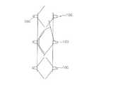
次に、LEDユニット5,6の構成を説明する。なお、第1LEDユニット5も第2LEDユニット6も基本的な構成は同じでよいので、第1LEDユニット5についてのみ説明する。まず、図7A,図7Bは、本発明に係る遮光手段の機能を備えていないLEDユニット5の構成を示す図である。LED50は、LED基板51の上に搭載され、基板モジュールを構成している。LED50は、出力6Wクラスの白色LEDである。第1LEDユニット5は、LED50を2つ並設した構成であるが、LED50を配置する個数は1個あるいは3個以上等、適宜設定することができる。<LED unit>
Next, the configuration of the
LED50及びLED基板51は、反射板52に収納されている。反射板52は、樹脂で成型することができ、LED50を収容するための凹部52aが形成される。凹部52aは、正面視で楕円もしくは長円に形成される。また、凹部52aの内面は反射面52bとして機能し、LED50からの照射光を前方に向けて反射させる。反射面52bは、表面にアルミ蒸着あるいはアルミメッキ等を施すことで形成することができる。 The
図7Bは、LED50からの照射光の照射範囲を示す図である。この場合、図の上方に向けて照射される光が不要な方向の照射光である。 FIG. 7B is a diagram illustrating an irradiation range of irradiation light from the
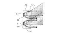
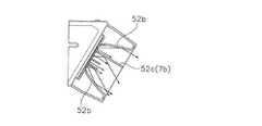
図8A,図8Bは、本発明に係る遮光手段の機能を備えたLEDユニット5を示す図である。図8Cは遮光部材(遮光手段に相当する)のみを示す図である。不要な方向への光を遮光するために図8Cに示すような遮光部材7を用いる。遮光部材7は、金属プレートあるいは樹脂により形成される。遮光部材7は、ネジ穴7aが左右両側に設けられており、ネジ8により支持体52にネジ止めされる。遮光部材7は、横桟部7bと縦桟部7cを備えている。横桟部7bは、図8Aにも示すように、反射板52に取り付けたときに、LED50よりも若干上方に位置している。縦桟部7cは、中央よりも少し右寄りに位置している。横桟部7bや縦桟部7cの配置については、適宜変更することが可能である。 8A and 8B are diagrams showing the
図8Aにおいては、反射板52にも縦桟部52c,52dが一体形成されている。一方の縦桟部52cは、左右方向において、遮光部材7の縦桟部7cと同じ位置に形成されている。このように、横桟部や縦桟部は、反射板52の側に一体形成してもよく、遮光部材7と組み合わせて、適切に設けることができる。 In FIG. 8A,
図8Bは、LED50からの照射光の照射範囲を示す図である。横桟部7cはLED50の近傍まで伸びており、効果的に不要な光を横桟部7cで反射させている。これにより、不要な上方への光が下方へと反射される。図7Bと比較すれば、遮光部材7の効果は直ちに理解できる。 FIG. 8B is a diagram illustrating an irradiation range of irradiation light from the
図8に示すLEDユニットの構成は、図3に示す第1・第2LEDユニット5,6のいずれに対しても適用できる構成である。LEDユニット5,6が配置される場所により、LED50の並び方向や、LEDユニット5,6自体の取り付け角度(傾斜角度)は異なっているが、横桟部や縦桟部などの遮光部材7を設けるという技術的思想は、どのLEDユニット5,6に対しても適用できるものである。桟部を設ける方向は横や縦だけでなく、斜めにしてもよく、また直線ではなく曲線的に設けてもよい。多数配置されるLEDユニット5,6のうち、遮光部材(遮光手段)が設けられないものがあってもよい。 The configuration of the LED unit shown in FIG. 8 is applicable to both the first and
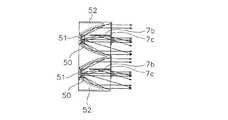
図7及び図8Bは、横長のLED50及びLED基板51の長手方向に垂直な方向の照明光を反射させる遮光手段について、主に説明した。図9は、横長のLED50及びLED基板51の短辺方向に垂直な方向の照明光について、遮光手段を設けていない場合の照射領域を示す。図9は、上方へ不要な光が照射されている例を示している。図10は、かかる不要な光を遮光する横桟部52cまたは7bを設けた例を示す。横桟部52cまたは7bを設けることで、不要な照射領域を制限し、適切な照射領域を設定することができる。 7 and 8B have mainly described the light shielding means for reflecting the illumination light in the direction perpendicular to the longitudinal direction of the horizontally
<別実施形態>
本発明に係る照明器具の一例として道路照明器具をあげたが、本発明はこれに限定されるものではない。道路照明以外の照明器具、例えば、オフィスビル等の建物内、室内、公園その他の施設、トンネル等においても適用することができる。<Another embodiment>
Although the road lighting fixture was mentioned as an example of the lighting fixture which concerns on this invention, this invention is not limited to this. The present invention can also be applied to lighting equipment other than road lighting, for example, in buildings such as office buildings, indoors, parks and other facilities, and tunnels.
LEDユニットの配列態様は、本実施形態に限定されるものではなく、種々の変形例が可能である。 The arrangement of the LED units is not limited to the present embodiment, and various modifications are possible.
1 下側本体ケース
2 上側本体ケース
5 第1LEDユニット
6 第2LEDユニット
7 遮光部材
7b 縦桟部
7c 横桟部
10 第1収容凹部
11 第2収容凹部
50 LED
51 LED基板
52 反射板
52a 凹部
52b 反射面
52c 縦桟部
52d 横桟部
100 道路照明器具DESCRIPTION OF
51
Claims (3)
Translated fromJapaneseLEDからの照射光の照射領域を制限する遮光手段を前記LEDユニットに設けていることを特徴とする照明器具。A plurality of LED units each having an LED and a reflective surface, and a lighting device in which the direction of the reflective surface is individually set for each LED unit so as to irradiate irradiation light to a peripheral region,
A lighting apparatus, wherein the LED unit is provided with a light shielding means for limiting an irradiation area of light emitted from the LED.
Priority Applications (1)
| Application Number | Priority Date | Filing Date | Title |
|---|---|---|---|
| JP2011042516AJP2012181950A (en) | 2011-02-28 | 2011-02-28 | Lighting fixture |
Applications Claiming Priority (1)
| Application Number | Priority Date | Filing Date | Title |
|---|---|---|---|
| JP2011042516AJP2012181950A (en) | 2011-02-28 | 2011-02-28 | Lighting fixture |
Publications (1)
| Publication Number | Publication Date |
|---|---|
| JP2012181950Atrue JP2012181950A (en) | 2012-09-20 |
Family
ID=47013000
Family Applications (1)
| Application Number | Title | Priority Date | Filing Date |
|---|---|---|---|
| JP2011042516AWithdrawnJP2012181950A (en) | 2011-02-28 | 2011-02-28 | Lighting fixture |
Country Status (1)
| Country | Link |
|---|---|
| JP (1) | JP2012181950A (en) |
Cited By (3)
| Publication number | Priority date | Publication date | Assignee | Title |
|---|---|---|---|---|
| JP2014102923A (en)* | 2012-11-19 | 2014-06-05 | Koito Mfg Co Ltd | Lighting system |
| JP5624642B2 (en)* | 2013-04-05 | 2014-11-12 | アイリスオーヤマ株式会社 | LED lighting device |
| JP2024130074A (en)* | 2023-03-14 | 2024-09-30 | 星和電機株式会社 | Road lighting device and road lighting system |
- 2011
- 2011-02-28JPJP2011042516Apatent/JP2012181950A/ennot_activeWithdrawn
Cited By (4)
| Publication number | Priority date | Publication date | Assignee | Title |
|---|---|---|---|---|
| JP2014102923A (en)* | 2012-11-19 | 2014-06-05 | Koito Mfg Co Ltd | Lighting system |
| JP5624642B2 (en)* | 2013-04-05 | 2014-11-12 | アイリスオーヤマ株式会社 | LED lighting device |
| JP2024130074A (en)* | 2023-03-14 | 2024-09-30 | 星和電機株式会社 | Road lighting device and road lighting system |
| JP7733039B2 (en) | 2023-03-14 | 2025-09-02 | 星和電機株式会社 | Road lighting device and road lighting system |
Similar Documents
| Publication | Publication Date | Title |
|---|---|---|
| JP6539665B2 (en) | Sports lighting equipment | |
| JP4999881B2 (en) | Tunnel lighting system | |
| JP5895187B2 (en) | LED lighting fixtures | |
| JP6111633B2 (en) | lighting equipment | |
| JP6902704B2 (en) | Road lighting | |
| JP2012181950A (en) | Lighting fixture | |
| JP6003434B2 (en) | Vehicle lighting | |
| JP2016054093A (en) | Vehicle lighting | |
| JP6320110B2 (en) | Vehicle lamp with license lamp | |
| RU2012157723A (en) | EXTERNAL LIGHTING DEVICE | |
| JP5736540B2 (en) | lighting equipment | |
| JP6720593B2 (en) | Road lighting lens and road lighting equipment | |
| JP6019993B2 (en) | Vehicle headlamp | |
| JP2021082565A (en) | Lighting device | |
| JP2021039866A (en) | Lighting fixture unit | |
| JP6459252B2 (en) | Vehicle lighting | |
| JP6398476B2 (en) | Light source unit and lighting apparatus | |
| JP6028412B2 (en) | Light source unit and lighting apparatus | |
| JP6560582B2 (en) | Louver and floodlight | |
| JP6171414B2 (en) | Light source unit and lighting apparatus | |
| JP6409418B2 (en) | Light source unit and lighting apparatus | |
| JP2012155939A (en) | Lighting fixture | |
| JP6578706B2 (en) | Vehicle lighting | |
| JP6263768B2 (en) | Light emitting element unit and lighting apparatus | |
| JP2016054094A (en) | Vehicle lighting |
Legal Events
| Date | Code | Title | Description |
|---|---|---|---|
| A300 | Application deemed to be withdrawn because no request for examination was validly filed | Free format text:JAPANESE INTERMEDIATE CODE: A300 Effective date:20140513 |