JP2012181052A - Correlation suppression filter, weight calculation method, weight calculation device, adaptive array antenna, and radar device - Google Patents
Correlation suppression filter, weight calculation method, weight calculation device, adaptive array antenna, and radar deviceDownload PDFInfo
- Publication number
- JP2012181052A JP2012181052AJP2011043035AJP2011043035AJP2012181052AJP 2012181052 AJP2012181052 AJP 2012181052AJP 2011043035 AJP2011043035 AJP 2011043035AJP 2011043035 AJP2011043035 AJP 2011043035AJP 2012181052 AJP2012181052 AJP 2012181052A
- Authority
- JP
- Japan
- Prior art keywords
- received
- signal
- weight
- target
- received signal
- Prior art date
- Legal status (The legal status is an assumption and is not a legal conclusion. Google has not performed a legal analysis and makes no representation as to the accuracy of the status listed.)
- Pending
Links
Images


Classifications
- G—PHYSICS
- G01—MEASURING; TESTING
- G01S—RADIO DIRECTION-FINDING; RADIO NAVIGATION; DETERMINING DISTANCE OR VELOCITY BY USE OF RADIO WAVES; LOCATING OR PRESENCE-DETECTING BY USE OF THE REFLECTION OR RERADIATION OF RADIO WAVES; ANALOGOUS ARRANGEMENTS USING OTHER WAVES
- G01S7/00—Details of systems according to groups G01S13/00, G01S15/00, G01S17/00
- G01S7/02—Details of systems according to groups G01S13/00, G01S15/00, G01S17/00 of systems according to group G01S13/00
- G01S7/28—Details of pulse systems
- G01S7/2813—Means providing a modification of the radiation pattern for cancelling noise, clutter or interfering signals, e.g. side lobe suppression, side lobe blanking, null-steering arrays
- G—PHYSICS
- G01—MEASURING; TESTING
- G01S—RADIO DIRECTION-FINDING; RADIO NAVIGATION; DETERMINING DISTANCE OR VELOCITY BY USE OF RADIO WAVES; LOCATING OR PRESENCE-DETECTING BY USE OF THE REFLECTION OR RERADIATION OF RADIO WAVES; ANALOGOUS ARRANGEMENTS USING OTHER WAVES
- G01S3/00—Direction-finders for determining the direction from which infrasonic, sonic, ultrasonic, or electromagnetic waves, or particle emission, not having a directional significance, are being received
- G01S3/02—Direction-finders for determining the direction from which infrasonic, sonic, ultrasonic, or electromagnetic waves, or particle emission, not having a directional significance, are being received using radio waves
- G01S3/74—Multi-channel systems specially adapted for direction-finding, i.e. having a single antenna system capable of giving simultaneous indications of the directions of different signals
Landscapes
- Engineering & Computer Science (AREA)
- Radar, Positioning & Navigation (AREA)
- Remote Sensing (AREA)
- Physics & Mathematics (AREA)
- General Physics & Mathematics (AREA)
- Computer Networks & Wireless Communication (AREA)
- Radar Systems Or Details Thereof (AREA)
Abstract
Description
Translated fromJapanese本実施形態は、受信信号において目標信号との相関を抑圧する相関抑圧フィルタ、相関抑圧フィルタ適用後の受信信号に対するウェイト制御を行うに際して、不要波を抑圧して目標からの反射信号を検出するのに好適なウェイトを算出するウェイト算出方法、そのウェイト算出方法を用いたウェイト算出装置、そのウェイト算出装置を採用したアダプティブアレーアンテナ、及びそのアダプティブアレーアンテナを組み込んだレーダ装置に関する。 In this embodiment, a correlation suppression filter that suppresses correlation with a target signal in a received signal, and weight control for the received signal after application of the correlation suppression filter, detects a reflected signal from the target by suppressing unnecessary waves. The present invention relates to a weight calculation method for calculating a weight suitable for the weight calculation device, a weight calculation device using the weight calculation method, an adaptive array antenna employing the weight calculation device, and a radar device incorporating the adaptive array antenna.
近年、パルスレーダ装置では、より目標検出精度を向上させるために、アダプティブアレーアンテナを組み込んで、いわゆるアダプティブヌルステアリングを行うようになってきている。このアダプティブヌルステアリングは、アダプティブアレーアンテナにおいて受信信号の位相及び振幅にウェイト制御を施すことで、妨害波等の不要波が到来する方向の指向性が零(ヌル)になるように受信合成ビームを形成する処理である。このような用途に用いられるアダプティブアレーアンテナには、多数の遅延信号が到来する環境下やクラッタ及び妨害波等の不要波が存在する環境下においても、上記の受信合成ビームの形成が適正に行われるようにウェイト制御を行うことが求められている。 In recent years, in order to further improve the target detection accuracy, pulse radar apparatuses have incorporated an adaptive array antenna to perform so-called adaptive null steering. This adaptive null steering performs weight control on the phase and amplitude of the received signal in the adaptive array antenna, and the received combined beam is set so that the directivity in the direction in which an unwanted wave such as an interference wave arrives becomes zero (null). It is a process to form. The adaptive array antenna used for such applications properly forms the received combined beam even in an environment where a large number of delayed signals arrive or an environment where unnecessary waves such as clutter and jamming waves exist. Therefore, it is required to perform weight control.
そこで、アダプティブアレーアンテナにおいて、サイドローブキャンセラー(SLC:Side Lobe Canceller)方式や時空間適応信号処理(STAP:Space Time Adaptive Processing)方式を採用した、ウェイト制御方法が注目されている。これは、サイドローブキャンセラー(SLC)方式や時空間適応信号処理(STAP)方式では、SINR(Signal to Interference plus Noise Ratio)をより改善し、不要波の到来方向での指向性が零(ヌル)に近い良好なビーム形成を行い得るという特徴を有するからである。 In view of this, a weight control method that employs a side lobe canceller (SLC) system or a space time adaptive signal processing (STAP) system is drawing attention in adaptive array antennas. This is because the sidelobe canceller (SLC) method and spatio-temporal adaptive signal processing (STAP) method improve SINR (Signal to Interference plus Noise Ratio) and zero directivity in the arrival direction of unnecessary waves (null). This is because it has a feature that good beam formation close to that can be performed.
例えば、時空間適応信号処理(STAP)方式では、以下のような処理が行われる。まず、複数(N)本、アレー状に配列されたアンテナ(素子アンテナ、すなわちチャンネル)により目標反射信号を受信し、その受信信号を、受信パルス幅に対応した幅のレンジ(距離)セル(range cell)が時間軸上に所定の長さで連なるように形成された、全処理レンジセルの対応セル位置に記憶する。そして、その記憶されたデータから、目標信号を含むと想定されるレンジセル(処理適用レンジセルという)を除いたレンジセル、すなわち不要波のみから形成されると想定されるセルのデータから共分散行列を演算する。最終的に、ビーム合成回路において、ウェイトの適用範囲毎に算出した適応ウェイトを用いて、アンテナ受信信号にウェイト制御を施すようにしている。 For example, in the space-time adaptive signal processing (STAP) method, the following processing is performed. First, a target reflected signal is received by a plurality (N) of antennas (element antennas, that is, channels) arranged in an array, and the received signal is converted into a range (distance) cell (range) having a width corresponding to the received pulse width. cell) is stored in the corresponding cell positions of all the processing range cells formed so as to be continuous with a predetermined length on the time axis. Then, from the stored data, the covariance matrix is calculated from the data of the range cell excluding the range cell that is assumed to contain the target signal (referred to as the processing applied range cell), that is, the cell that is assumed to be formed only from unnecessary waves. To do. Finally, the beam combining circuit performs weight control on the antenna reception signal using the adaptive weight calculated for each weight application range.
しかしながら、従来のレーダ装置に用いられるアダプティブアレーアンテナのウェイト制御による不要信号抑圧方式では、不要波方向を零にするためのウェイト算出時の受信信号に目標信号が存在すると、不要信号だけでなく目標信号も抑圧してしまう。これを回避するため、受信信号を複数の範囲に分割し、ウェイトを適用する範囲を除いたデータからウェイトを算出していたため、ウェイトの適用範囲毎にウェイトを算出する必要があり、多くの演算時間を要していた。 However, in the unnecessary signal suppression method based on weight control of the adaptive array antenna used in the conventional radar apparatus, if the target signal exists in the received signal when calculating the weight to make the unnecessary wave direction zero, not only the unnecessary signal but also the target signal The signal is also suppressed. In order to avoid this, the received signal was divided into multiple ranges and the weights were calculated from the data excluding the range to which the weights were applied, so it was necessary to calculate the weights for each weight application range, and many operations It took time.
本実施形態は上記の課題に鑑みてなされたもので、ウェイト制御による適応信号処理方式において、不要波方向を零にするためのウェイト算出時に、目標信号との相関を抑圧する相関抑圧フィルタ、相関抑圧フィルタ適用後のデータから適応ウェイトを求め、少ない計算量で良好な改善度を実現するウェイト算出方法、ウェイト算出装置、アダプティブアレーアンテナ、及びレーダ装置を提供することを目的とする。 The present embodiment has been made in view of the above problems. In an adaptive signal processing method based on weight control, a correlation suppression filter that suppresses correlation with a target signal at the time of calculating a weight for making the unnecessary wave direction zero, a correlation An object of the present invention is to provide a weight calculation method, a weight calculation device, an adaptive array antenna, and a radar device that obtain an adaptive weight from data after applying a suppression filter and realize a good improvement with a small amount of calculation.
上記問題を解決するために、本実施形態に係る相関抑圧フィルタは、アレー状に配列された複数のアンテナ素子によってレーダパルスの目標反射信号を受信し、各アンテナ素子それぞれの受信信号を時間軸上で所定距離相当の長さからなる複数の処理レンジセルに対して受信タイミングに沿った対応セル位置に記憶し、前記アンテナ素子毎に複数の処理レンジセルに記憶された値を用いて前記目標反射信号の到来方向に対して不要波の到来方向が零になるように受信合成ビームを形成するアダプティプアレーアンテナを備えるレーダ装置に用いられ、前記受信合成ビームを形成するための前記受信信号の位相及び振幅に対するウェイトを算出する前処理として、前記レーダパルスの送信波形の標本値であるリファレンス信号を用いて目標信号との相関を抑圧するフィルタ係数を予め算出する係数算出手段と、前記係数算出手段で算出されたフィルタ係数を前記受信信号に適用することで、受信信号から目標信号成分を除去する係数適用手段とを具備する態様とする。 In order to solve the above problem, the correlation suppression filter according to the present embodiment receives a target reflected signal of a radar pulse by a plurality of antenna elements arranged in an array, and the received signal of each antenna element is on the time axis. And stored in the corresponding cell position along the reception timing for a plurality of processing range cells having a length corresponding to a predetermined distance, and using the values stored in the plurality of processing range cells for each antenna element, Phase and amplitude of the received signal for forming the received combined beam, used in a radar apparatus having an adaptive array antenna that forms a received combined beam so that the direction of arrival of unwanted waves is zero with respect to the direction of arrival As a preprocessing for calculating a weight for the target signal, a reference signal that is a sample value of the transmission waveform of the radar pulse is used. Coefficient calculating means for preliminarily calculating a filter coefficient for suppressing the correlation of the coefficient, and coefficient applying means for removing the target signal component from the received signal by applying the filter coefficient calculated by the coefficient calculating means to the received signal. It is set as the aspect to comprise.
以下、図面を参照して本実施形態について説明する。
まず、実施形態として、
(1)リファレンス信号を用いて相関抑圧フィルタの係数を予め算出して受信信号に適用した場合、
(2)複数のリファレンス信号を用いて複数の相関抑圧フィルタの係数を予め算出して受信信号に適用した場合、
(3)受信信号からリファレンス信号を推定して相関抑圧フィルタの係数を動的に算出して受信信号に適用した場合、
(4)これらの相関抑圧フィルタを多段に具備して受信信号に適用した場合、
の各受信信号から目標信号成分を除去した信号に対してウェイトを算出し、演算時間を高速化する方法について説明する。なお、上記(1)〜(4)の全てにおいて、相関抑圧フィルタの導出方法は同一である。Hereinafter, this embodiment will be described with reference to the drawings.
First, as an embodiment,
(1) When the coefficient of the correlation suppression filter is calculated in advance using the reference signal and applied to the received signal,
(2) When the coefficients of a plurality of correlation suppression filters are calculated in advance using a plurality of reference signals and applied to the received signal,
(3) When the reference signal is estimated from the received signal and the coefficient of the correlation suppression filter is dynamically calculated and applied to the received signal,
(4) When these correlation suppression filters are provided in multiple stages and applied to a received signal,
A method for calculating the weight for the signal obtained by removing the target signal component from each received signal and increasing the calculation time will be described. In all of the above (1) to (4), the method for deriving the correlation suppression filter is the same.
さて、受信信号に対して、パルス圧縮フィルタへの入力信号系列ベクトルA- (- はベクトルを表すものとする)を次の(1)式で与える。
これは、レーダの送信源から割り当てた符号に対応した入力信号系列ベクトルである。すなわち、このベクトル要素は、送信パルス内でのレンジ方向の時間順のI/Qサンプリングデータとし、レーダ送信波形の標本値(リファレンス信号)に相当する。This is an input signal sequence vector corresponding to the code assigned from the radar transmission source. That is, this vector element is I / Q sampling data in time order in the range direction in the transmission pulse, and corresponds to a sample value (reference signal) of the radar transmission waveform.
次いで、パルス圧縮フィルタ回路への入力信号状態マトリックスXを、次の(2)式で与える。
さらに、パルス圧縮フィルタにおけるフィルタ係数ベクトルは、NタップのFIRフィルタ係数ベクトルH- として、次の(3)式で表現できる。
ここで、F- は最適フィルタ(マッチドフィルタ)のN次係数ベクトル、Wは窓関数に相当しN次元の対角行列とする。
これらを用い、パルス圧縮フィルタの出力時系列yは、次の(4)式で表現できる。
Using these, the output time series y of the pulse compression filter can be expressed by the following equation (4).
ここで、T は転置行列を示す。Here,T represents a transposed matrix.
(4)式をFFT周波数スペクトルと対応させると、次の(5)式のように表現できる。
ここで、演算マトリックスとして、FFT演算マトリックスQ及びIFFT演算マトリックスQ^をそれぞれ(6)及び(7)式で定義する。
また、FFTポイント数Nf は、パルス圧縮フィルタの出力時系列ポイント数(2N−1)よりも大きいものとする。Further, the FFT point number Nf is larger than the output time series point number (2N−1) of the pulse compression filter.
さらに、FFTポイント数Nf に合わせて、(8)、(9)、(10)、(11)及び(12)式のように、0を付加する。
さらに、主ローブ近傍±Nx ポイントを除いた(0とした)出力ベクトル、すなわち目標信号(期待値)ym を次の(13)式で与えるものとする。
ここで、(4)式で示したように、目標信号のパルス圧縮フィルタの出力時系列ymzは、次の(14)式で表現できる。
さて、(13)及び(14)式から明らかなように、Hdzは目標信号を抑圧する係数ベクトルであり、次の(15)〜(21)式を用いて算出できる。
なお、(1)式の入力信号系列ベクトルA- を、他の入力信号系列に変更することで、容易に複数のリファレンス信号に対する相関抑圧フィルタが実現可能である。また、受信信号からリファレンス信号、すなわち、目標信号を推定し、入力信号系列ベクトルとして用いることも可能である。加えて、相関抑圧フィルタ適用後の信号に対して、目標信号を抑圧するフィルタを、受信信号に対して複数回、上記と同様の処理を実施することも可能である。さらには、複数回に渡って相関抑圧フィルタを適用する際、リファレンス信号を変更することも可能である。さらに、±Nxの設定値をサイドローブ領域まで広げることで、主ローブ近傍だけでなく、サイドローブ領域も抑圧することが可能である。It should be noted that a correlation suppression filter for a plurality of reference signals can be easily realized by changing the input signal sequence vector A− in equation (1) to another input signal sequence. It is also possible to estimate a reference signal, that is, a target signal from a received signal and use it as an input signal sequence vector. In addition, a filter that suppresses the target signal can be subjected to the same processing as described above a plurality of times for the received signal with respect to the signal after the correlation suppression filter is applied. Furthermore, the reference signal can be changed when applying the correlation suppression filter a plurality of times. Furthermore, by extending the set value of ± Nx to the side lobe region, it is possible to suppress not only the vicinity of the main lobe but also the side lobe region.
ここで、本実施形態の一例として、FFTポイント数512、Nx =6、目標が存在するレンジビン128において、導出した相関抑圧フィルタ適用の受信信号を図1に示す。図1から、パルス圧縮フィルタによる処理結果では図中実線で示すように存在する目標信号が、相関抑圧フィルタを適用することで、図中点線で示すように抑圧されていることが分かる。Here, as an example of this embodiment, FIG. 1 shows a reception signal to which a correlation suppression filter is derived, derived in the
さて、本実施形態の一例として、相関抑圧フィルタ適用後の受信信号を用いて不要信号抑圧ウェイトを導出する一例として、時空間適応信号処理(STAP)方式を考える。 As an example of this embodiment, a space-time adaptive signal processing (STAP) system is considered as an example of deriving an unnecessary signal suppression weight using a received signal after application of a correlation suppression filter.
受信信号Xの到来方向の方向行列をA、また複素振幅ベクトルをS、平均0,分散σ2 で与えられる熱雑音をnとしたとき、受信信号Xは次の(22)式で表される。
また、間隔dxをなしてアレー状に配列されたN個のアンテナ#n(n:1〜N)により目標信号を受信したとき、受信周波数信号の波長をλ(Λ)、D個の到来目標信号d(d:1〜D)の到来方向を決めるステアリングベクトルa(θd)は、次の(23)式で表される。
ここで、角度方向、すなわち、空間系列に対する方向行列Aθは下記(24)式となる。
さらに、目標信号dのドップラー周波数をfd、M個の受信パルスの間隔をTとすると、時間方向のステアリングベクトルa(fd)は次の(25)式で示される。
このことから、全ての受信パルスに対する、時系列の方向行列Afは下記(26)式で表される。
よって、方向行列A(θ,f)は、次の(27)式
で表される時空間ステアリングベクトルa(θd, fd)を用いて、下記(28)式で与えられる。
ここで、時刻kにおける(NM×1)次元の入力ベクトルをxk とすると、K個分のデータから算出される共分散行列Rは(29)式で与えられる。
例えば、一つの目標に対するウィナ・フィルタ(Wiener Filter)のウェイトwは、(28)式におけるステアリングベクトルa(θd, fd)を選択しこれをsとすると、(30)式で算出される。
このとき、アンテナ数N、受信パルス数M、距離(レンジ数)Lの場合での受信信号とウェイト適用の概念図を図2に示す。図2では、k〜k+K/2-1及びk+K〜k+3K/2までのK個分のデータにウェイトを適用する様子を示している。図2及び(30)式から、ウェイトの算出には、NM次元の逆行列演算が必要であることが分かる。また、図2では、k+K/2〜k+K-1までのK/2個分の受信信号にウェイトを適用する場合を示しているが、受信信号全てに対してウェイトを計算する必要があり、ウェイトを適用するデータ分割数に従って、ウェイトの計算時間(ウェイト計算数)が増加することが分かる。 At this time, FIG. 2 shows a conceptual diagram of reception signals and weight application in the case of the number of antennas N, the number of received pulses M, and the distance (number of ranges) L. FIG. 2 shows a state in which weights are applied to K pieces of data from k to k + K / 2-1 and k + K to k + 3K / 2. From FIG. 2 and equation (30), it can be seen that the calculation of the weight requires an NM-dimensional inverse matrix operation. FIG. 2 shows a case where weights are applied to K / 2 received signals from k + K / 2 to k + K−1, but it is necessary to calculate weights for all received signals. It can be seen that the weight calculation time (number of weight calculations) increases according to the number of data divisions to which weights are applied.
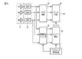
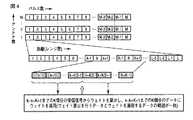
さて、導出した相関抑圧フィルタ適用後に不要信号抑圧処理としてSTAPを適用する場合の概念について、図3及び図4を参照して説明する。図3は本実施形態に係る相関抑圧フィルタを用いたレーダ装置の構成、図4はアンテナ数N、受信パルス数M、距離(レンジ数)Lの場合での受信信号と本実施形態のウェイト適用の場合の概念図を示している。 Now, the concept of applying STAP as unnecessary signal suppression processing after applying the derived correlation suppression filter will be described with reference to FIGS. 3 and 4. FIG. FIG. 3 shows the configuration of the radar apparatus using the correlation suppression filter according to the present embodiment. FIG. 4 shows the received signal and the weight application of the present embodiment when the number of antennas is N, the number of received pulses is M, and the distance is the number of ranges. The conceptual diagram in the case of is shown.
図3において、アレーアンテナ1のアンテナ素子#1〜#Nで受けた信号はそれぞれA/D変換部2によりデジタル信号に変換された後、パルス圧縮回路3に送られる。このパルス圧縮回路3は、予め所定距離相当の長さの処理レンジセルに対応する記憶領域を備え、入力データを受信タイミングに沿った対応セル位置の記憶領域に順次記憶しつつ、順次ビーム合成回路4に送られる。 In FIG. 3, signals received by the
一方、上記デジタル化された受信データは相関抑圧フィルタ回路5を介してウェイト算出回路6に送られる。上記相関抑圧フィルタ回路5及びウェイト算出回路6には、リファレンス信号生成回路7で生成されるリファレンス信号が与えられる。 On the other hand, the digitized reception data is sent to the
すなわち、上記構成によるレーダ装置では、リファレンス信号を用いて相関抑圧フィルタ回路5おける受信信号全てに対して相関抑圧フィルタ処理を適用し、相関抑圧フィルタ適用後のデータを用いてウェイト算出回路6にてリファレンス信号に基づく不要信号抑圧ウェイトを計算し、次いで、相関抑圧フィルタを適用していない受信信号に対して、不要信号抑圧ウェイトを適用してビーム合成回路4にてビーム形成を行う。この結果、図4に示すように、k〜k+K+1までのk個分の受信信号からウェイトを算出し、k〜k+K+1までのK個分のデータにウェイトを適用することになり、ウェイト算出を行うデータとウェイトを適用するデータの範囲が一致することになる。 That is, in the radar apparatus having the above configuration, the correlation suppression filter process is applied to all the received signals in the correlation
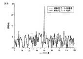
ここで、本実施形態の一例として、目標が存在するレンジビン64において、全ての受信信号に相関抑圧フィルタを非適用で不要信号抑圧処理を実施した場合、並びに、相関抑圧フィルタを適用した後に不要信号抑圧処理を実施した場合の出力データを図5に示す。図5において、実線が相関抑圧フィルタ非適用の場合、一点鎖線が相関抑圧フィルタ適用の場合を示している。図に示すように、相関抑圧フィルタを適用しない場合は、受信信号に目標信号成分が存在するため、不要信号抑圧処理により目標が抑圧されてしまうが、相関抑圧フィルタを適用することで目標信号が抑圧されていないことが分かる。 Here, as an example of the present embodiment, in the
したがって、本実施形態に係わる(1)リファレンス信号を用いて相関抑圧フィルタの係数を予め算出して受信信号に適用、または、(2)複数のリファレンス信号を用いて複数の相関抑圧フィルタの係数を予め算出して受信信号に適用、または、(3)受信信号からリファレンス信号を推定して相関抑圧フィルタの係数を動的に算出して受信信号に適用、または、(4)これらの相関抑圧フィルタを多段に具備して受信信号に適用することで、受信信号から目標信号成分を確実に除去することができる。このため、目標信号の抑圧を回避することを目的として受信信号を複数の範囲に分割し、ウェイトを適用する範囲を除いたデータからウェイトの適用範囲毎にウェイトを算出する必要がなくなることから、受信信号に対して最低一回の計算で得ることが可能となり、演算時間の高速化と目標のドップラー周波数に対して良好なSINR特性を得ることができる。 Therefore, according to the present embodiment, (1) the coefficient of the correlation suppression filter is calculated in advance using the reference signal and applied to the received signal, or (2) the coefficient of the plurality of correlation suppression filters is used using the plurality of reference signals. Pre-calculated and applied to the received signal, or (3) Estimating the reference signal from the received signal and dynamically calculating the coefficient of the correlation suppression filter and applying it to the received signal, or (4) These correlation suppression filters Can be applied to the received signal, and the target signal component can be reliably removed from the received signal. For this reason, it is not necessary to divide the received signal into a plurality of ranges for the purpose of avoiding suppression of the target signal, and to calculate the weight for each weight application range from the data excluding the range to which the weight is applied. It is possible to obtain the received signal by at least one calculation, and it is possible to obtain a high SINR characteristic with respect to the target Doppler frequency and a high calculation time.
図6は本実施形態に係るウェイト算出装置の一実施形態を示すブロック図である。図6において、11はCPU(演算処理装置)であり、このCPU11はバス12を通じてプログラム記憶用ROM13、データ入出力インターフェース(I/O)14、データ一時記憶用RAM15に接続されている。ROM13には、本実施形態に係わるウェイト算出プログラムが格納されており、処理開始が指示されると、CPU11はROM13からプログラムをロードし、データ入出力インターフェース14を介してデータを取り込んでRAM15に一時格納し、当該RAM15から適宜データを読み出して、ウェイト演算処理を実行し、得られたウェイト演算結果をインターフェース14から出力する。 FIG. 6 is a block diagram showing an embodiment of a weight calculation apparatus according to this embodiment. In FIG. 6, reference numeral 11 denotes a CPU (arithmetic processing unit), which is connected to a
上記構成による本実施形態のウェイト算出装置は、目標のドップラー周波数に対してSINR劣化を抑制する上記本実施形態に係るウェイト算出方法を使用するので、良好なSINR特性を得ることが可能である。そこで、このウェイト算出装置をアダプティブアレイアンテナに採用し、個々のアンテナ素子の入出力に対するウェイト算出を行わせる。これによれば、良好なSINR特性を有する合成ビームを形成することが可能となる。 The weight calculation apparatus according to the present embodiment having the above-described configuration uses the weight calculation method according to the present embodiment that suppresses SINR degradation with respect to the target Doppler frequency. Therefore, it is possible to obtain good SINR characteristics. Therefore, this weight calculation device is employed in an adaptive array antenna to calculate weights for input / output of individual antenna elements. According to this, it is possible to form a combined beam having good SINR characteristics.
ところで、アダプティブアレイアンテナは、目標を捕捉するための合成開口レーダ装置等のレーダ装置に採用されている。そこで、上記のようにアダプティブアレイアンテナに本実施形態のウェイト算出装置を採用することで、良好なSINR特性を有する合成ビームを形成することが可能となる。このため、このアンテナを用いるレーダ装置にあっては、目標をより良好に捕捉することができるようになる。 Incidentally, adaptive array antennas are employed in radar devices such as a synthetic aperture radar device for capturing a target. Thus, by employing the weight calculation apparatus of the present embodiment for the adaptive array antenna as described above, it is possible to form a combined beam having good SINR characteristics. For this reason, in the radar apparatus using this antenna, the target can be captured better.
上記レーダ装置の一例として、図7に本実施形態を適用した適応信号処理におけるウェイト算出装置が組み込まれたレーダ装置の概略ブロック構成図を示す。図7において、21はN個のアンテナ素子でレーダパルスの目標反射信号を受信するアダプティブアレーアンテナである。このアンテナ21の各素子出力は、それぞれ励振受信部22で受信検波されて信号処理部27に送られる。信号処理部27では、パルス圧縮回路271において、予め所定距離相当の長さの処理レンジセルに対応する記憶領域が用意されており、入力データは受信タイミングに沿った対応セル位置の記憶領域に順次記憶され、順次ビーム合成回路276に送られる。 As an example of the radar apparatus, FIG. 7 shows a schematic block configuration diagram of a radar apparatus in which a weight calculation apparatus in adaptive signal processing to which the present embodiment is applied is incorporated. In FIG. 7,
ここで、一部のアンテナ素子出力はリファレンス信号推定回路273に送られ、受信信号の振幅・位相の基準として用いられる。励振受信部22は、リファレンス信号推定回路273及びリファレンス信号生成回路274を定期的に励振させて、所定距離相当のレンジセルそれぞれのウェイト算出のためのリファレンス信号を推定し生成する。 Here, part of the antenna element output is sent to the reference
また、信号処理部27は、ウェイト算出回路275において、(1)リファレンス信号を用いて相関抑圧フィルタ回路272の係数を予め算出して受信信号に適用、または、(2)複数のリファレンス信号を用いて複数の相関抑圧フィルタ回路272の係数を予め算出して受信信号に適用、または、(3)受信信号からリファレンス信号を推定して相関抑圧フィルタ回路272の係数を動的に算出して受信信号に適用、または、(4)これらの相関抑圧フィルタを多段に具備して受信信号に適用することで、受信信号から目標信号成分が除去したデータから適応ウェイトを算出する。最終的に、ビーム合成回路276において、導出された適応ウェイトによりアンテナ受信信号にウェイト制御を施して出力データとする。このように、アダプティブアレーアンテナでウェイト制御が施された出力データ、すなわち目標反射信号は信号処理装置28に送られ、目標が検出される。 Further, the signal processing unit 27, in the
上記構成の適応信号処理方式におけるウェイト制御では、適応ウェイトを算出するために、ウェイト算出回路275において、レンジセル毎のウェイト演算が行われる。このウェイト算出回路275に先に述べたウェイト算出方法、すなわち、(1)リファレンス信号を用いて相関抑圧フィルタ回路272の係数を予め算出して受信信号に適用、または、(2)複数のリファレンス信号を用いて複数の相関抑圧フィルタ回路272の係数を予め算出して受信信号に適用、または、(3)受信信号からリファレンス信号を推定して相関抑圧フィルタ回路272の係数を動的に算出して受信信号に適用、または、(4)これらの相関抑圧フィルタを多段に具備して受信信号に適用することで受信信号から目標信号成分が除去される。 In the weight control in the adaptive signal processing method having the above-described configuration, the
上記のような処理を行うことにより、目標信号の抑圧を回避することを目的として受信信号を複数の範囲に分割し、ウェイトを適用する範囲を除いたデータからウェイトの適用範囲毎にウェイトを算出する必要がなくなり、受信信号に対して最低一回の計算で得ることが可能なため、演算時間の高速化と目標のドップラー周波数に対して良好なSINR特性を得ることができる。 By performing the above processing, the received signal is divided into multiple ranges for the purpose of avoiding suppression of the target signal, and the weight is calculated for each weight application range from the data excluding the range to which the weight is applied. Therefore, it is possible to obtain the received signal with at least one calculation, so that it is possible to obtain a high SINR characteristic with respect to a high calculation time and a target Doppler frequency.
ここで、図8に本実施形態を適用した相関抑圧フィルタ回路275の処理フローを示す。この相関抑圧フィルタ回路272は、リファレンス信号生成回路274においてリファレンス信号が事前に決定された場合に係数を事前に決定しておく処理S1と、リファレンス信号推定回路273において受信信号から目標反射信号に対応するリファレンス信号が推定された場合に係数を動的に算出する処理S2を備え、いずれかの処理S1,S2を選択処理S3により任意に選択可能とする。続いて、選択処理S4により、初期処理においては、ステップS1,S2で得られた係数を適用し(ステップS5)、定常動作時では係数を距離に応じて切り替えて適用する(ステップS6)。 Here, FIG. 8 shows a processing flow of the correlation
上記のように相関抑圧フィルタ回路272で適用された係数はウェイト算出回路275に送られる。このウェイト算出回路275では、距離に応じて決定された係数または演算時間と信号処理利得に応じて決定されたパルス数と、事前に決定されたリファレンス信号または推定されたリファレンス信号に基づいてウェイト算出アルゴリズムを選択し、適応ウェイトを算出する。 The coefficients applied by the correlation
尚、ウェイト算出回路275は、全ての受信信号に対して算出した適応ウェイトを積分する処理と、全ての受信信号に対して算出した適応ウェイトに複素ウェイトを乗算して積分する処理とを備え、選択処理によっていずれかの処理を選択可能とする。算出された積分結果はビーム合成回路276に送られてビーム合成されて出力データとなる。 The
続いて、上記ビーム合成された出力データは、出力データから目標検出結果が得られるかどうか判断し、出力データに対する目標検出結果が得られない場合は演算時間の上限までウェイト算出に用いるパルス数を増加するように指示する。これにより、目標検出結果からウェイト算出に用いる受信パルスを自動的に選択することが可能となる。 Subsequently, the beam-combined output data is determined whether or not a target detection result can be obtained from the output data. If the target detection result for the output data cannot be obtained, the number of pulses used for weight calculation up to the upper limit of the calculation time is determined. Instruct to increase. Thereby, it is possible to automatically select a reception pulse used for weight calculation from the target detection result.
以上のように、本実施形態に係るウェイト算出方法では、目標反射信号の到来方向に対して不要波の到来方向を零になるようにするためのウェイト算出方式において、ウェイト算出に用いる受信信号を、リファレンス信号を用いて相関抑圧フィルタの係数を予め算出して受信信号に適用、または、複数のリファレンス信号を用いて複数の相関抑圧フィルタの係数を予め算出して受信信号に適用、または、受信信号からリファレンス信号を推定して相関抑圧フィルタの係数を動的に算出して受信信号に適用、または、これらの相関抑圧フィルタを多段に具備して受信信号に適用することで受信信号から目標信号成分が除去されるため、目標信号の抑圧を回避することを目的として受信信号を複数の範囲に分割し、ウェイトを適用する範囲を除いたデータからウェイトを算出することで、ウェイトの適用範囲毎にウェイトを算出する必要がなく、受信信号に対して最低一回の計算得るため演算時間の高速化が可能であり、演算時間の高速化と目標のドップラー周波数に対して良好なSINR特性を得ることができる。 As described above, in the weight calculation method according to the present embodiment, in the weight calculation method for making the arrival direction of the unwanted wave zero with respect to the arrival direction of the target reflected signal, the received signal used for weight calculation is calculated. The correlation suppression filter coefficient is calculated in advance using the reference signal and applied to the received signal, or the multiple correlation suppression filter coefficients are calculated in advance using the plurality of reference signals and applied to the received signal or received. The reference signal is estimated from the signal and the coefficient of the correlation suppression filter is dynamically calculated and applied to the received signal. Alternatively, these correlation suppression filters are provided in multiple stages and applied to the received signal. Since the component is removed, the received signal is divided into multiple ranges for the purpose of avoiding suppression of the target signal, and the range where weights are applied is excluded By calculating the weight from the data, it is not necessary to calculate the weight for each application range of the weight, and the calculation time can be increased because the calculation can be performed at least once for the received signal. As a result, a good SINR characteristic can be obtained with respect to the target Doppler frequency.
また、本実施形態のウェイト算出装置は、上記のように、ウェイト算出に用いる受信信号を、リファレンス信号を用いて相関抑圧フィルタの係数を予め算出して受信信号に適用、または、複数のリファレンス信号を用いて複数の相関抑圧フィルタの係数を予め算出して受信信号に適用、または、受信信号からリファレンス信号を推定して相関抑圧フィルタの係数を動的に算出して受信信号に適用、または、これらの相関抑圧フィルタを多段に具備して受信信号に適用することで受信信号から目標信号成分が除去されるため、目標信号の抑圧を回避することを目的として受信信号を複数の範囲に分割し、ウェイトを適用する範囲を除いたデータからウェイトの適用範囲毎にウェイトを算出する必要がなく、受信信号に対して最低一回の計算得るため演算時間の高速化が可能であり、演算時間の高速化と目標のドップラー周波数に対して良好なSINR特性を得ることができる。 Further, as described above, the weight calculation apparatus according to the present embodiment applies the received signal used for weight calculation to the received signal by calculating the coefficient of the correlation suppression filter in advance using the reference signal, or a plurality of reference signals. The coefficient of a plurality of correlation suppression filters is calculated in advance using and applied to the received signal, or the reference signal is estimated from the received signal and the coefficient of the correlation suppression filter is dynamically calculated and applied to the received signal, or Since these correlation suppression filters are provided in multiple stages and applied to the received signal, the target signal component is removed from the received signal. Therefore, the received signal is divided into a plurality of ranges in order to avoid suppression of the target signal. It is not necessary to calculate the weight for each weight application range from the data excluding the range to which the weight is applied, and the calculation can be performed at least once for the received signal. It is possible faster because the calculation time, it is possible to obtain a good SINR characteristics for high-speed and the target Doppler frequency calculation time.
また、本実施形態のアダプティブアレイアンテナは、上記のように、ウェイト算出の時間短縮が可能なウェイト算出回路を採用するので、良好な合成ビームを短時間に形成することができる。 In addition, as described above, the adaptive array antenna according to the present embodiment employs a weight calculation circuit capable of shortening the time for weight calculation, so that a good combined beam can be formed in a short time.
また、本実施形態のレーダ装置は、上記のように、合成ビームを短時間に形成することが可能なアダプティブアレイアンテナを組み込むので、目標を迅速に捕捉することができる。 In addition, as described above, the radar apparatus according to the present embodiment incorporates an adaptive array antenna that can form a combined beam in a short time, and thus can quickly capture a target.
尚、上記実施形態はそのままに限定されるものではなく、実施段階ではその要旨を逸脱しない範囲で構成要素を変形して具体化できる。また、上記実施形態に開示されている複数の構成要素の適宜な組み合わせでもよい。例えば、実施形態に示される全構成要素から幾つかの構成要素を削除してもよい。さらに、異なる実施形態にわたる構成要素を適宜組み合わせてもよい。 In addition, the said embodiment is not limited as it is, In the implementation stage, a component can be deform | transformed and embodied in the range which does not deviate from the summary. Moreover, an appropriate combination of a plurality of constituent elements disclosed in the above embodiment may be used. For example, some components may be deleted from all the components shown in the embodiment. Furthermore, constituent elements over different embodiments may be appropriately combined.
1…アレーアンテナ、2…A/D変換部、3…パルス圧縮回路、4…ビーム合成回路、5…相関抑圧フィルタ回路、6…ウェイト算出回路、7…リファレンス信号生成回路、11…CPU、12…バス、13…プログラム記憶用ROM、14…データ入出力インターフェース、15…データ一時格納用RAM、21…アダプティブアレーアンテナ、22…励振受信部、27…信号処理部、271…パルス圧縮回路、272…相関抑圧フィルタ回路、273…リファレンス信号推定回路、274…リファレンス信号生成回路、275…ウェイト算出回路、276…ビーム合成回路。 DESCRIPTION OF
Claims (9)
Translated fromJapanese前記受信合成ビームを形成するための前記受信信号の位相及び振幅に対するウェイトを算出する前処理として、
前記レーダパルスの送信波形の標本値であるリファレンス信号を用いて目標信号との相関を抑圧するフィルタ係数を予め算出する係数算出手段と、
前記係数算出手段で算出されたフィルタ係数を前記受信信号に適用することで、受信信号から目標信号成分を除去する係数適用手段と
を具備することを特徴とする相関抑圧フィルタ。The target reflected signal of the radar pulse is received by a plurality of antenna elements arranged in an array, and the received signal of each antenna element is received for a plurality of processing range cells having a length corresponding to a predetermined distance on the time axis. Is received at the corresponding cell position along the line and received and combined so that the arrival direction of the unnecessary wave becomes zero with respect to the arrival direction of the target reflected signal using the values stored in the plurality of processing range cells for each antenna element. Used in radar equipment with an adaptive array antenna that forms a beam,
As pre-processing for calculating weights for the phase and amplitude of the received signal for forming the received combined beam,
Coefficient calculation means for calculating in advance a filter coefficient for suppressing correlation with a target signal using a reference signal that is a sample value of a transmission waveform of the radar pulse;
A correlation suppression filter comprising coefficient applying means for removing a target signal component from a received signal by applying the filter coefficient calculated by the coefficient calculating means to the received signal.
前記受信合成ビームを形成するための前記受信信号の位相及び振幅に対するウェイトを算出する前処理として、
前記レーダパルスの送信波形の標本値である複数のリファレンス信号を用いて目標信号との相関を抑圧する複数のフィルタ係数を予め算出する係数算出手段と、
前記係数算出手段で算出された複数のフィルタ係数を前記受信信号の距離に応じて動的に変更して前記受信信号に適用することで、前記受信信号から目標信号成分を除去する係数適用手段と
を具備することを特徴とする相関抑圧フィルタ。The target reflected signal of the radar pulse is received by a plurality of antenna elements arranged in an array, and the received signal of each antenna element is received for a plurality of processing range cells having a length corresponding to a predetermined distance on the time axis. Is received at the corresponding cell position along the line and received and combined so that the arrival direction of the unnecessary wave becomes zero with respect to the arrival direction of the target reflected signal using the values stored in the plurality of processing range cells for each antenna element. Used in radar equipment with an adaptive array antenna that forms a beam,
As pre-processing for calculating weights for the phase and amplitude of the received signal for forming the received combined beam,
Coefficient calculation means for calculating in advance a plurality of filter coefficients for suppressing correlation with a target signal using a plurality of reference signals that are sample values of the transmission waveform of the radar pulse;
Coefficient applying means for removing a target signal component from the received signal by dynamically changing a plurality of filter coefficients calculated by the coefficient calculating means according to the distance of the received signal and applying them to the received signal; A correlation suppression filter comprising:
前記受信合成ビームを形成するための前記受信信号の位相及び振幅に対するウェイトを算出する前処理として、
前記受信信号から前記レーダパルスの送信波形の標本値であるリファレンス信号を推定して目標信号との相関を抑圧するためのフィルタ係数を動的に算出する係数算出手段と、
前記係数算出手段で算出されたフィルタ係数を受信信号に適用することで、受信信号から目標信号成分を除去する係数適用手段と
を具備することを特徴とする相関抑圧フィルタ。The target reflected signal of the radar pulse is received by a plurality of antenna elements arranged in an array, and the received signal of each antenna element is received for a plurality of processing range cells having a length corresponding to a predetermined distance on the time axis. Is received at the corresponding cell position along the line and received and combined so that the arrival direction of the unnecessary wave becomes zero with respect to the arrival direction of the target reflected signal using the values stored in the plurality of processing range cells for each antenna element. Used in radar equipment with an adaptive array antenna that forms a beam,
As pre-processing for calculating weights for the phase and amplitude of the received signal for forming the received combined beam,
Coefficient calculation means for dynamically calculating a filter coefficient for estimating a reference signal which is a sample value of a transmission waveform of the radar pulse from the received signal and suppressing correlation with a target signal;
A correlation suppression filter comprising coefficient applying means for removing a target signal component from a received signal by applying the filter coefficient calculated by the coefficient calculating means to the received signal.
前記請求項1乃至4のいずれか記載の相関抑圧フィルタで得られる受信信号から前記適応ウェイトを算出することを特徴とするウェイト算出方法。The target reflected signal of the radar pulse is received by a plurality of antenna elements arranged in an array, and the received signal of each antenna element is received for a plurality of processing range cells having a length corresponding to a predetermined distance on the time axis. Is applied to the received signals stored in the plurality of processing range cells for each antenna element, and the arrival direction of the unwanted wave is zero with respect to the arrival direction of the target reflected signal. It is used in a radar apparatus having an adaptive array antenna that forms a received combined beam so that
The weight calculation method characterized by calculating the said adaptive weight from the received signal obtained by the correlation suppression filter in any one of the said Claim 1 thru | or 4.
前記請求項1乃至4のいずれか記載の相関抑圧フィルタで得られる受信信号から前記適応ウェイトを算出するウェイト算出手段を備えることを特徴とするウェイト算出装置。The target reflected signal of the radar pulse is received by a plurality of antenna elements arranged in an array, and the received signal of each antenna element is received for a plurality of processing range cells having a length corresponding to a predetermined distance on the time axis. Is applied to the received signals stored in the plurality of processing range cells for each antenna element, and the arrival direction of the unwanted wave is zero with respect to the arrival direction of the target reflected signal. It is used in a radar apparatus having an adaptive array antenna that forms a received combined beam so that
5. A weight calculating apparatus comprising weight calculating means for calculating the adaptive weight from a received signal obtained by the correlation suppression filter according to claim 1.
前記請求項1乃至4のいずれか記載の相関抑圧フィルタと、
前記相関抑圧フィルタで得られる受信信号から前記適応ウェイトを算出するウェイト算出手段と、
前記適応ウェイトにより前記アンテナ素子毎の受信信号にウェイト制御を施して前記受信合成ビームを形成するビーム形成手段と
を具備することを特徴とするアダプティプアレーアンテナ。The target reflected signal of the radar pulse is received by a plurality of antenna elements arranged in an array, and the received signal of each antenna element is received for a plurality of processing range cells having a length corresponding to a predetermined distance on the time axis. Is applied to the received signals stored in the plurality of processing range cells for each antenna element, and the arrival direction of the unwanted wave is zero with respect to the arrival direction of the target reflected signal. An adaptive array antenna that forms a received combined beam so that
The correlation suppression filter according to any one of claims 1 to 4,
Weight calculating means for calculating the adaptive weight from the received signal obtained by the correlation suppression filter;
An adaptive array antenna comprising beam forming means for performing weight control on a received signal for each antenna element by the adaptive weight to form the received combined beam.
前記アダプティブアレーアンテナでウェイト制御が施された目標反射信号から目標を検出する信号処理装置と
を具備することを特徴とするレーダ装置。The target reflected signal of the radar pulse is received by a plurality of antenna elements arranged in an array, and the received signal of each antenna element is received for a plurality of processing range cells having a length corresponding to a predetermined distance on the time axis. Is applied to the received signals stored in the plurality of processing range cells for each antenna element, and the arrival direction of the unwanted wave is zero with respect to the arrival direction of the target reflected signal. An adaptive array antenna that forms a received combined beam so that the adaptive weight is calculated from the correlation suppression filter according to any one of claims 1 to 4 and a reception signal obtained by the correlation suppression filter. Weight calculation means and weight control is performed on the reception signal for each antenna element by the adaptive weight to perform the reception synthesis beacon. And adapter Tipu array antenna and a beam forming means for forming a
A radar apparatus, comprising: a signal processing device that detects a target from a target reflection signal that has been subjected to weight control by the adaptive array antenna.
Priority Applications (2)
| Application Number | Priority Date | Filing Date | Title |
|---|---|---|---|
| JP2011043035AJP2012181052A (en) | 2011-02-28 | 2011-02-28 | Correlation suppression filter, weight calculation method, weight calculation device, adaptive array antenna, and radar device |
| US13/361,382US20120218139A1 (en) | 2011-02-28 | 2012-01-30 | Correlation filter for target suppression, weight calculation method, weight calculation device, adaptive array antenna, and radar device |
Applications Claiming Priority (1)
| Application Number | Priority Date | Filing Date | Title |
|---|---|---|---|
| JP2011043035AJP2012181052A (en) | 2011-02-28 | 2011-02-28 | Correlation suppression filter, weight calculation method, weight calculation device, adaptive array antenna, and radar device |
Publications (1)
| Publication Number | Publication Date |
|---|---|
| JP2012181052Atrue JP2012181052A (en) | 2012-09-20 |
Family
ID=46718619
Family Applications (1)
| Application Number | Title | Priority Date | Filing Date |
|---|---|---|---|
| JP2011043035APendingJP2012181052A (en) | 2011-02-28 | 2011-02-28 | Correlation suppression filter, weight calculation method, weight calculation device, adaptive array antenna, and radar device |
Country Status (2)
| Country | Link |
|---|---|
| US (1) | US20120218139A1 (en) |
| JP (1) | JP2012181052A (en) |
Cited By (1)
| Publication number | Priority date | Publication date | Assignee | Title |
|---|---|---|---|---|
| JP5474241B1 (en)* | 2013-07-26 | 2014-04-16 | 株式会社ソニック | Pulse compression correlation coefficient generation circuit and pulse compression ultrasonic detector |
Families Citing this family (13)
| Publication number | Priority date | Publication date | Assignee | Title |
|---|---|---|---|---|
| US9535156B2 (en) | 2013-03-15 | 2017-01-03 | Src, Inc. | Passive listening pulse adaptive sidelobe canceller |
| JP6260004B2 (en)* | 2013-08-29 | 2018-01-17 | パナソニックIpマネジメント株式会社 | Radar system and target detection method |
| CN104640210B (en)* | 2013-11-15 | 2019-04-30 | 深圳市中兴微电子技术有限公司 | A baseband data storage control method and device |
| CN106233684B (en)* | 2014-05-08 | 2019-11-29 | 华为技术有限公司 | Channel Estimation in Wireless Communication Network Nodes |
| US9559803B2 (en) | 2015-04-03 | 2017-01-31 | National Security Technologies, Llc | Electromagnetic spectrum management system |
| US9912467B2 (en)* | 2015-09-22 | 2018-03-06 | Qualcomm Incorporated | Full duplex technique |
| US10320467B2 (en) | 2015-09-29 | 2019-06-11 | The United States Of America, As Represented By The Secretary Of The Army | Frequency-based radio beamforming waveform transmission |
| US10193612B2 (en)* | 2015-09-29 | 2019-01-29 | The United States Of America, As Represented By The Secretary Of The Army | Time-based radio beamforming waveform transmission |
| US10079633B2 (en) | 2015-09-29 | 2018-09-18 | The United States Of America, As Represented By The Secretary Of The Army | Time-based and frequency-based radio beamforming waveform transmission |
| US10856303B2 (en)* | 2017-10-06 | 2020-12-01 | Lg Electronics Inc. | Method for performing measurement and device supporting the same |
| WO2020148802A1 (en)* | 2019-01-15 | 2020-07-23 | 三菱電機株式会社 | Beam formation device, radar device, and beam formation method |
| CN112241668B (en)* | 2019-07-18 | 2024-06-28 | 杭州海康威视数字技术股份有限公司 | Image processing method, device and equipment |
| CN112684444B (en)* | 2020-11-30 | 2023-09-22 | 中国科学院空天信息创新研究院 | Method and device for suppressing distance ambiguity based on antenna pattern synthesis |
Citations (3)
| Publication number | Priority date | Publication date | Assignee | Title |
|---|---|---|---|---|
| JP2007003325A (en)* | 2005-06-23 | 2007-01-11 | Toshiba Corp | Covariance matrix calculation method, weight calculation circuit, adaptive array antenna, and radar apparatus |
| JP2008032438A (en)* | 2006-07-26 | 2008-02-14 | Toshiba Corp | Weight calculation method, weight calculation device, adaptive array antenna, and radar device |
| JP2008032435A (en)* | 2006-07-26 | 2008-02-14 | Toshiba Corp | Weight calculation method, weight calculation device, adaptive array antenna, and radar device |
Family Cites Families (3)
| Publication number | Priority date | Publication date | Assignee | Title |
|---|---|---|---|---|
| JP4834370B2 (en)* | 2005-06-30 | 2011-12-14 | 株式会社東芝 | Correlation reception processing device |
| JP4939888B2 (en)* | 2005-10-05 | 2012-05-30 | パナソニック株式会社 | Wireless communication device |
| WO2009081981A1 (en)* | 2007-12-25 | 2009-07-02 | Honda Elesys Co., Ltd. | Electronic scanning radar apparatus, received wave direction estimating method, and received wave direction estimating program |
- 2011
- 2011-02-28JPJP2011043035Apatent/JP2012181052A/enactivePending
- 2012
- 2012-01-30USUS13/361,382patent/US20120218139A1/ennot_activeAbandoned
Patent Citations (3)
| Publication number | Priority date | Publication date | Assignee | Title |
|---|---|---|---|---|
| JP2007003325A (en)* | 2005-06-23 | 2007-01-11 | Toshiba Corp | Covariance matrix calculation method, weight calculation circuit, adaptive array antenna, and radar apparatus |
| JP2008032438A (en)* | 2006-07-26 | 2008-02-14 | Toshiba Corp | Weight calculation method, weight calculation device, adaptive array antenna, and radar device |
| JP2008032435A (en)* | 2006-07-26 | 2008-02-14 | Toshiba Corp | Weight calculation method, weight calculation device, adaptive array antenna, and radar device |
Cited By (1)
| Publication number | Priority date | Publication date | Assignee | Title |
|---|---|---|---|---|
| JP5474241B1 (en)* | 2013-07-26 | 2014-04-16 | 株式会社ソニック | Pulse compression correlation coefficient generation circuit and pulse compression ultrasonic detector |
Also Published As
| Publication number | Publication date |
|---|---|
| US20120218139A1 (en) | 2012-08-30 |
Similar Documents
| Publication | Publication Date | Title |
|---|---|---|
| JP2012181052A (en) | Correlation suppression filter, weight calculation method, weight calculation device, adaptive array antenna, and radar device | |
| JP4138825B2 (en) | Weight calculation method, weight calculation device, adaptive array antenna, and radar device | |
| JP4709117B2 (en) | Radar device and angle measuring device | |
| JP5371248B2 (en) | Radar equipment | |
| JP4553387B2 (en) | Weight calculation method, weight calculation device, adaptive array antenna, and radar device | |
| KR102099388B1 (en) | Method of estimating direction of arrival of radar signal based on antenna array extrapolation and apparatus for the same | |
| JP2009229104A (en) | Weight calculation method, weight calculation device, adaptive array antenna, and radar device | |
| JPS6088375A (en) | Coherent sidelobe canceller | |
| JP2011117899A (en) | Radar device | |
| JP5531299B2 (en) | Weight calculation method, weight calculation device, adaptive array antenna, and radar device | |
| JP4144195B2 (en) | Radar equipment | |
| JP2014044193A (en) | Clutter suppressing device | |
| JP5152949B2 (en) | Weight calculation method, weight calculation device, adaptive array antenna, and radar device | |
| JP2008032437A (en) | Weight calculation method, weight calculation device, adaptive array antenna, and radar device | |
| JP4444150B2 (en) | Filter device | |
| JP7384276B2 (en) | Communication device, communication method | |
| JP2001133538A (en) | Signal processing device and signal processing method | |
| JP2010060353A (en) | Radar equipment | |
| JP5241147B2 (en) | Unwanted signal suppression device | |
| JP2004257761A (en) | Radar signal processing apparatus and radar signal processing method | |
| JP4383977B2 (en) | Adaptive antenna device | |
| JP2008157679A (en) | Radar signal processing device | |
| JP4468203B2 (en) | Radar equipment | |
| JP5981369B2 (en) | Weight calculation method, weight calculation device, adaptive array antenna, and radar device | |
| JP4908352B2 (en) | Weight calculation method, weight calculation device, adaptive array antenna, and radar device |
Legal Events
| Date | Code | Title | Description |
|---|---|---|---|
| A621 | Written request for application examination | Free format text:JAPANESE INTERMEDIATE CODE: A621 Effective date:20130917 | |
| RD04 | Notification of resignation of power of attorney | Free format text:JAPANESE INTERMEDIATE CODE: A7424 Effective date:20131205 | |
| RD04 | Notification of resignation of power of attorney | Free format text:JAPANESE INTERMEDIATE CODE: A7424 Effective date:20131212 | |
| RD04 | Notification of resignation of power of attorney | Free format text:JAPANESE INTERMEDIATE CODE: A7424 Effective date:20131219 | |
| RD04 | Notification of resignation of power of attorney | Free format text:JAPANESE INTERMEDIATE CODE: A7424 Effective date:20131226 | |
| RD04 | Notification of resignation of power of attorney | Free format text:JAPANESE INTERMEDIATE CODE: A7424 Effective date:20140109 | |
| A977 | Report on retrieval | Free format text:JAPANESE INTERMEDIATE CODE: A971007 Effective date:20140228 | |
| A131 | Notification of reasons for refusal | Free format text:JAPANESE INTERMEDIATE CODE: A131 Effective date:20140304 | |
| A521 | Written amendment | Free format text:JAPANESE INTERMEDIATE CODE: A523 Effective date:20140430 | |
| A131 | Notification of reasons for refusal | Free format text:JAPANESE INTERMEDIATE CODE: A131 Effective date:20140610 | |
| A521 | Written amendment | Free format text:JAPANESE INTERMEDIATE CODE: A523 Effective date:20140807 | |
| A02 | Decision of refusal | Free format text:JAPANESE INTERMEDIATE CODE: A02 Effective date:20140909 |