JP2012178854A - Optical flow based tilt sensor - Google Patents
Optical flow based tilt sensorDownload PDFInfo
- Publication number
- JP2012178854A JP2012178854AJP2012096580AJP2012096580AJP2012178854AJP 2012178854 AJP2012178854 AJP 2012178854AJP 2012096580 AJP2012096580 AJP 2012096580AJP 2012096580 AJP2012096580 AJP 2012096580AJP 2012178854 AJP2012178854 AJP 2012178854A
- Authority
- JP
- Japan
- Prior art keywords
- feature
- movement
- image
- camera
- image sensor
- Prior art date
- Legal status (The legal status is an assumption and is not a legal conclusion. Google has not performed a legal analysis and makes no representation as to the accuracy of the status listed.)
- Pending
Links
Images


Classifications
- H—ELECTRICITY
- H04—ELECTRIC COMMUNICATION TECHNIQUE
- H04N—PICTORIAL COMMUNICATION, e.g. TELEVISION
- H04N1/00—Scanning, transmission or reproduction of documents or the like, e.g. facsimile transmission; Details thereof
- H04N1/00127—Connection or combination of a still picture apparatus with another apparatus, e.g. for storage, processing or transmission of still picture signals or of information associated with a still picture
- H04N1/00281—Connection or combination of a still picture apparatus with another apparatus, e.g. for storage, processing or transmission of still picture signals or of information associated with a still picture with a telecommunication apparatus, e.g. a switched network of teleprinters for the distribution of text-based information, a selective call terminal
- H04N1/00307—Connection or combination of a still picture apparatus with another apparatus, e.g. for storage, processing or transmission of still picture signals or of information associated with a still picture with a telecommunication apparatus, e.g. a switched network of teleprinters for the distribution of text-based information, a selective call terminal with a mobile telephone apparatus
- G—PHYSICS
- G06—COMPUTING OR CALCULATING; COUNTING
- G06F—ELECTRIC DIGITAL DATA PROCESSING
- G06F1/00—Details not covered by groups G06F3/00 - G06F13/00 and G06F21/00
- G06F1/16—Constructional details or arrangements
- G06F1/1613—Constructional details or arrangements for portable computers
- G06F1/1626—Constructional details or arrangements for portable computers with a single-body enclosure integrating a flat display, e.g. Personal Digital Assistants [PDAs]
- G—PHYSICS
- G06—COMPUTING OR CALCULATING; COUNTING
- G06F—ELECTRIC DIGITAL DATA PROCESSING
- G06F1/00—Details not covered by groups G06F3/00 - G06F13/00 and G06F21/00
- G06F1/16—Constructional details or arrangements
- G06F1/1613—Constructional details or arrangements for portable computers
- G06F1/1633—Constructional details or arrangements of portable computers not specific to the type of enclosures covered by groups G06F1/1615 - G06F1/1626
- G06F1/1684—Constructional details or arrangements related to integrated I/O peripherals not covered by groups G06F1/1635 - G06F1/1675
- G06F1/1686—Constructional details or arrangements related to integrated I/O peripherals not covered by groups G06F1/1635 - G06F1/1675 the I/O peripheral being an integrated camera
- G—PHYSICS
- G06—COMPUTING OR CALCULATING; COUNTING
- G06F—ELECTRIC DIGITAL DATA PROCESSING
- G06F3/00—Input arrangements for transferring data to be processed into a form capable of being handled by the computer; Output arrangements for transferring data from processing unit to output unit, e.g. interface arrangements
- G06F3/01—Input arrangements or combined input and output arrangements for interaction between user and computer
- G06F3/03—Arrangements for converting the position or the displacement of a member into a coded form
- G06F3/033—Pointing devices displaced or positioned by the user, e.g. mice, trackballs, pens or joysticks; Accessories therefor
- G06F3/0346—Pointing devices displaced or positioned by the user, e.g. mice, trackballs, pens or joysticks; Accessories therefor with detection of the device orientation or free movement in a 3D space, e.g. 3D mice, 6-DOF [six degrees of freedom] pointers using gyroscopes, accelerometers or tilt-sensors
- G—PHYSICS
- G06—COMPUTING OR CALCULATING; COUNTING
- G06T—IMAGE DATA PROCESSING OR GENERATION, IN GENERAL
- G06T7/00—Image analysis
- G06T7/20—Analysis of motion
- G06T7/269—Analysis of motion using gradient-based methods
- G—PHYSICS
- G06—COMPUTING OR CALCULATING; COUNTING
- G06V—IMAGE OR VIDEO RECOGNITION OR UNDERSTANDING
- G06V10/00—Arrangements for image or video recognition or understanding
- G06V10/10—Image acquisition
- G06V10/17—Image acquisition using hand-held instruments
- G—PHYSICS
- G06—COMPUTING OR CALCULATING; COUNTING
- G06V—IMAGE OR VIDEO RECOGNITION OR UNDERSTANDING
- G06V40/00—Recognition of biometric, human-related or animal-related patterns in image or video data
- G06V40/20—Movements or behaviour, e.g. gesture recognition
- H—ELECTRICITY
- H04—ELECTRIC COMMUNICATION TECHNIQUE
- H04N—PICTORIAL COMMUNICATION, e.g. TELEVISION
- H04N1/00—Scanning, transmission or reproduction of documents or the like, e.g. facsimile transmission; Details thereof
- H04N1/00127—Connection or combination of a still picture apparatus with another apparatus, e.g. for storage, processing or transmission of still picture signals or of information associated with a still picture
- H04N1/00323—Connection or combination of a still picture apparatus with another apparatus, e.g. for storage, processing or transmission of still picture signals or of information associated with a still picture with a measuring, monitoring or signaling apparatus, e.g. for transmitting measured information to a central location
- H—ELECTRICITY
- H04—ELECTRIC COMMUNICATION TECHNIQUE
- H04N—PICTORIAL COMMUNICATION, e.g. TELEVISION
- H04N1/00—Scanning, transmission or reproduction of documents or the like, e.g. facsimile transmission; Details thereof
- H04N1/0035—User-machine interface; Control console
- H04N1/00352—Input means
- H04N1/00381—Input by recognition or interpretation of visible user gestures
- A—HUMAN NECESSITIES
- A63—SPORTS; GAMES; AMUSEMENTS
- A63F—CARD, BOARD, OR ROULETTE GAMES; INDOOR GAMES USING SMALL MOVING PLAYING BODIES; VIDEO GAMES; GAMES NOT OTHERWISE PROVIDED FOR
- A63F2300/00—Features of games using an electronically generated display having two or more dimensions, e.g. on a television screen, showing representations related to the game
- A63F2300/10—Features of games using an electronically generated display having two or more dimensions, e.g. on a television screen, showing representations related to the game characterized by input arrangements for converting player-generated signals into game device control signals
- A63F2300/1087—Features of games using an electronically generated display having two or more dimensions, e.g. on a television screen, showing representations related to the game characterized by input arrangements for converting player-generated signals into game device control signals comprising photodetecting means, e.g. a camera
- G—PHYSICS
- G06—COMPUTING OR CALCULATING; COUNTING
- G06F—ELECTRIC DIGITAL DATA PROCESSING
- G06F2200/00—Indexing scheme relating to G06F1/04 - G06F1/32
- G06F2200/16—Indexing scheme relating to G06F1/16 - G06F1/18
- G06F2200/163—Indexing scheme relating to constructional details of the computer
- G06F2200/1637—Sensing arrangement for detection of housing movement or orientation, e.g. for controlling scrolling or cursor movement on the display of an handheld computer
- H—ELECTRICITY
- H04—ELECTRIC COMMUNICATION TECHNIQUE
- H04M—TELEPHONIC COMMUNICATION
- H04M1/00—Substation equipment, e.g. for use by subscribers
- H04M1/72—Mobile telephones; Cordless telephones, i.e. devices for establishing wireless links to base stations without route selection
- H04M1/724—User interfaces specially adapted for cordless or mobile telephones
- H04M1/72403—User interfaces specially adapted for cordless or mobile telephones with means for local support of applications that increase the functionality
- H04M1/72427—User interfaces specially adapted for cordless or mobile telephones with means for local support of applications that increase the functionality for supporting games or graphical animations
- H—ELECTRICITY
- H04—ELECTRIC COMMUNICATION TECHNIQUE
- H04M—TELEPHONIC COMMUNICATION
- H04M2250/00—Details of telephonic subscriber devices
- H04M2250/12—Details of telephonic subscriber devices including a sensor for measuring a physical value, e.g. temperature or motion
- H—ELECTRICITY
- H04—ELECTRIC COMMUNICATION TECHNIQUE
- H04M—TELEPHONIC COMMUNICATION
- H04M2250/00—Details of telephonic subscriber devices
- H04M2250/52—Details of telephonic subscriber devices including functional features of a camera
- H—ELECTRICITY
- H04—ELECTRIC COMMUNICATION TECHNIQUE
- H04N—PICTORIAL COMMUNICATION, e.g. TELEVISION
- H04N2201/00—Indexing scheme relating to scanning, transmission or reproduction of documents or the like, and to details thereof
- H04N2201/0077—Types of the still picture apparatus
- H04N2201/0084—Digital still camera
- H—ELECTRICITY
- H04—ELECTRIC COMMUNICATION TECHNIQUE
- H04N—PICTORIAL COMMUNICATION, e.g. TELEVISION
- H04N2201/00—Indexing scheme relating to scanning, transmission or reproduction of documents or the like, and to details thereof
- H04N2201/0096—Portable devices
Landscapes
- Engineering & Computer Science (AREA)
- Theoretical Computer Science (AREA)
- Multimedia (AREA)
- Human Computer Interaction (AREA)
- General Physics & Mathematics (AREA)
- Physics & Mathematics (AREA)
- General Engineering & Computer Science (AREA)
- Signal Processing (AREA)
- Computer Hardware Design (AREA)
- Computer Vision & Pattern Recognition (AREA)
- General Health & Medical Sciences (AREA)
- Psychiatry (AREA)
- Social Psychology (AREA)
- Health & Medical Sciences (AREA)
- Image Analysis (AREA)
- Studio Devices (AREA)
- User Interface Of Digital Computer (AREA)
Abstract
Description
Translated fromJapanese本開示は動きの推定に関する。 The present disclosure relates to motion estimation.
デジタルカメラは画像のデジタル表現を捕捉する。デジタルカメラは、指定の期間に亘って複数の画像を捕捉するように構成されていることがある。デジタル画像を処理することは、一つの画像の特性を検出するためにその画像の各特徴を処理すること、または撮像している環境の特性または画像捕捉装置の特性を特定するために一連の画像の各特徴を処理することを含んでいることがある。オプティカルフローとして知られる処理では、画像の中の物体とその画像捕捉装置との間の相対的な動きを検出するために、一連の画像における物体の配置を比較することがある。 A digital camera captures a digital representation of an image. A digital camera may be configured to capture multiple images over a specified period of time. Processing a digital image involves processing each feature of the image to detect the characteristics of an image, or a series of images to identify the characteristics of the environment being imaged or the characteristics of the image capture device May include processing each of the features. In a process known as optical flow, the placement of objects in a series of images may be compared to detect relative movement between the object in the image and its image capture device.
本明細書で説明する一つの概略の例では、デジタルカメラから捕捉する一連の画像をデジタルカメラの動きを検出するために分析してもよく、検出した動きに基づいて装置へのユーザー入力を特定してもよい。説明する各種の実施形態は以下の特徴のうちの一つ以上を有している。例えば、カメラ付き携帯電話などの携帯娯楽装置において傾きセンサーとしてオプティカルフローを使用することなどである。疎らな特徴群のセット/疎らなフロー場を、リアルタイム実行性能を実現するために使用してもよい。非静的な場面を、フロー場の最も典型的な(すなわち最大の静止しているクラスタ)結果を見つけることによって処理してもよい。長い期間にわたって、最初の位置および/または方向を基準とした位置および/または方向を算出してもよい。カメラが固定され、ユーザーの方ではない方向を向いているカメラ付き携帯電話において前記特徴を使用してもよい。限定的な処理能力を有する装置用に実施形態/特徴を構成してもよい。 In one schematic example described herein, a series of images captured from a digital camera may be analyzed to detect digital camera movement and identify user input to the device based on the detected movement. May be. Various described embodiments have one or more of the following features. For example, using an optical flow as a tilt sensor in a portable entertainment device such as a camera-equipped mobile phone. A set of sparse features / sparse flow fields may be used to achieve real-time execution performance. Non-static scenes may be processed by finding the most typical (ie, largest stationary cluster) result of the flow field. The position and / or direction relative to the initial position and / or direction may be calculated over a long period of time. The feature may be used in a camera-equipped mobile phone with the camera fixed and facing away from the user. Embodiments / features may be configured for devices with limited processing capabilities.
概略の態様に係る方法は、動いているモバイルカメラから画像を捕捉することと、前記捕捉された画像に基づいて前記動いているモバイルカメラの動きの様子を検出することとを含んでいる。前記方法はまた、インタフェース装置上にアプリケーションへのユーザーインタフェースを提供することも含んでいる。前記アプリケーションへのユーザー入力を、自動的に前記検出された動きに基づいて特定する。 The method according to the general aspect includes capturing an image from a moving mobile camera, and detecting a movement of the moving mobile camera based on the captured image. The method also includes providing a user interface to the application on the interface device. User input to the application is automatically identified based on the detected movement.
前記概略の態様の実施形態は、以下の特徴の一つ以上を有してもよい。例えば、前記インタフェース装置が前記モバイルカメラに物理的に結合されている、または前記モバイルカメラを有する装置に物理的に一体化されていてもよい。前記動いているモバイルカメラが携帯電話に物理的に結合されていてもよい。 Embodiments of the general aspect may have one or more of the following features. For example, the interface device may be physically coupled to the mobile camera or physically integrated with a device having the mobile camera. The moving mobile camera may be physically coupled to a mobile phone.
動きの様子を検出することは、自動的に実行されてもよく、大きさと方向のうちの一つ以上を検出することを含んでもよい。動きの様子を検出することは、また、オプティカルフローを使用することを含んでもよい。 Detecting the state of movement may be performed automatically and may include detecting one or more of magnitude and direction. Detecting the state of motion may also include using optical flow.
前記動いているモバイルカメラの動きの様子を検出することは、2または3自由度の前記動いているモバイルカメラの回転量を算出することを含んでもよい。前記動いているモバイルカメラの動きの様子を検出することは、また、前記動いているモバイルカメラの平行移動量を算出することも含んでよい。 Detecting the movement of the moving mobile camera may include calculating the amount of rotation of the moving mobile camera with two or three degrees of freedom. Detecting the movement of the moving mobile camera may also include calculating a translation amount of the moving mobile camera.
前記動いているモバイルカメラの動きの様子を検出することは、前記動いているモバイルカメラの最初の位置に対する前記動いているモバイルカメラの移動量を算出することを含んでもよい。前記動いているモバイルカメラの前記最初の位置が、アプリケーションによって再セットされてもよい。 Detecting the movement of the moving mobile camera may include calculating a moving amount of the moving mobile camera with respect to an initial position of the moving mobile camera. The initial position of the moving mobile camera may be reset by the application.
前記動いているモバイルカメラの動きの様子を検出することは、前記捕捉された画像中の特徴群の動きを検出することと、前記特徴群の前記動きに基づいて前記モバイルカメラの動きを検出することとを含んでもよい。前記特徴群の前記検出された動きに基づいて、前記特徴群を、基準の現実世界のフレームに対して動いている動的特徴群のセットに分けてもよい。動的特徴群に分けることは、最大の面積をカバーする特徴群のセットを選択することと、選択されなかった特徴を無視することとを含んでもよい。動的特徴群を分けることは、また、特徴群の重要なセットと類似の方向と大きさを有していない特徴を無視することを含んでもよい。 Detecting the movement of the moving mobile camera detects the movement of the feature group in the captured image and detects the movement of the mobile camera based on the movement of the feature group. May also be included. Based on the detected movement of the feature group, the feature group may be divided into a set of dynamic feature groups that are moving relative to a reference real-world frame. Dividing into dynamic feature groups may include selecting a set of feature groups that cover a maximum area and ignoring unselected features. Separating dynamic feature groups may also include ignoring features that do not have a direction and size similar to an important set of feature groups.
動きの様子を検出することは、前記捕捉された複数の画像から特徴を抽出することと、二つ以上の画像に存在している各特徴を対応付けるために画像を比較することとを含んでもよい。前の画像内の特徴の位置に対する現在の画像内のその特徴の位置の変位を算出することによって、対応付けられた特徴のフローベクトルを決定してもよい。前記各対応付けられた特徴の前記決定されたフローベクトルに基づいて前記モバイルカメラの前記動きを検出する。 Detecting the state of motion may include extracting features from the captured plurality of images and comparing the images to correlate each feature present in two or more images. . The flow vector of the associated feature may be determined by calculating the displacement of that feature location in the current image relative to the feature location in the previous image. The movement of the mobile camera is detected based on the determined flow vector of each associated feature.
前記捕捉された画像から特徴を抽出することは、角および縁の少なくとも一つを検出することを含んでもよい。各特徴を対応付けるために画像を比較することは、最初に、画像内の前記特徴の既知の位置と、近接した別の画像内のブロックとを比較することを含んでもよい。各特徴を対応付けるために画像を比較することは、また、最初に低解像度で画像を比較し、対応が見つかったかどうかに応じてより高い解像度で画像を比較することを含んでもよい。前記フローベクトルを基に前記モバイルカメラの前記動きを決定することは、画像に依存する単位で決定された前記動きを変換することによって現実世界の単位で前記モバイルカメラの前記動きを特定することを含んでもよい。 Extracting features from the captured image may include detecting at least one of corners and edges. Comparing images to associate each feature may include first comparing a known location of the feature in the image with a block in another adjacent image. Comparing the images to associate each feature may also include comparing the images first at a lower resolution and comparing the images at a higher resolution depending on whether a correspondence is found. Determining the movement of the mobile camera based on the flow vector includes identifying the movement of the mobile camera in real-world units by transforming the movement determined in image-dependent units. May be included.
画像を捕捉することに、一連の画像を捕捉することが含まれていてもよい。前記動いているモバイルカメラの動きの様子を検出することは、前記一連の画像のうち第1サブセットの画像に現れている第1の特徴の動きを検出することと、前記一連の画像うち、前記第1サブセットと部分的に重複した第2サブセットの画像に現れている第2の特徴であって、前記第1の特徴との間に、前記第1の特徴が前記第2サブセットの画像の全てには現れていない場合でも、第2の特徴の動きが前記第1の特徴の動きに基づいているという固定した物理的関係を有する第2の特徴の動きを検出することとを含んでもよい。前記第1と第2の特徴の検出された動きに基づいて、前記動いているモバイルカメラの動きの様子を検出してよい。 Capturing an image may include capturing a series of images. Detecting the movement of the moving mobile camera includes detecting a movement of a first feature appearing in a first subset of the series of images, and out of the series of images, A second feature appearing in an image of a second subset that partially overlaps the first subset, wherein the first feature includes all of the images of the second subset. Detecting a motion of the second feature having a fixed physical relationship that the motion of the second feature is based on the motion of the first feature, even if it does not appear. The movement of the moving mobile camera may be detected based on the detected movement of the first and second features.
前記ユーザー入力が傾きセンサー機能を模倣し、アプリケーション中で物体の傾き、またはアプリケーション中でボールの動き、またはアプリケーション中で乗り物の操縦機能、またはアプリケーション中で物体の照準合わせ機能、またはアプリケーション中で物体のナビゲーション機能、またはアプリケーション中で関節を有するキャラクタの動き、または粒子シミュレーションアプリケーション中の粒子の動きを制御してもよい。前記検出された動きの大きさがしきい値の大きさよりも大きいときに前記ユーザー入力が特定されてもよい。前記アプリケーションは、ゲーム、追跡アプリケーション、セキュリティアプリケーションのうちの少なくとも一つを含んでもよい。 The user input mimics the tilt sensor function, the tilt of the object in the application, or the movement of the ball in the application, or the vehicle steering function in the application, or the aiming function of the object in the application, or the object in the application Navigation functions, or movements of characters with joints in the application, or movements of particles in a particle simulation application. The user input may be specified when the detected magnitude of movement is greater than a threshold magnitude. The application may include at least one of a game, a tracking application, and a security application.
別の概略の態様によれば、携帯電話が、電話にそれぞれ一体的に形成されたカメラとディスプレイとを有している。前記電話はまた、前記カメラと前記ディスプレイとに物理的にかつ通信可能に接続された処理装置を有している。前記電話は、さらに、前記処理装置に物理的にかつ通信可能に接続されたコンピュータ読み取り可能な媒体を有している。前記コンピュータ読み取り可能な媒体は、少なくとも、(1)前記カメラから捕捉された画像を受け取ることと、(2)前記受け取った画像を基に前記電話の動きの様子を検出することと、(3)アプリケーションへのユーザーインタフェースを前記ディスプレイに提供することと、(4)前記電話の前記動きの様子に基づいて前記アプリケーションへのユーザー入力を自動的に特定することと、(5)前記アプリケーションに前記ユーザー入力を提供することとを、前記処理装置に実行させるための命令を有している。 According to another schematic aspect, a mobile phone has a camera and a display, each integrally formed on the phone. The telephone also includes a processing device physically and communicatively connected to the camera and the display. The telephone further includes a computer readable medium physically and communicatively connected to the processing unit. The computer readable medium is at least (1) receiving an image captured from the camera, (2) detecting a state of movement of the telephone based on the received image, and (3) Providing a user interface to the application on the display; (4) automatically identifying user input to the application based on the behavior of the phone; and (5) providing the user with the application. Providing an input has instructions for causing the processing device to execute.
前記概略の態様の実施形態は、様々なさらなる特徴を有していてもよい。例えば、前記コンピュータ読み取り可能な媒体は、前記処理装置の一体化された部分であってもよい。 Embodiments of the general aspect may have various additional features. For example, the computer readable medium may be an integral part of the processing device.
各種の態様、実施形態、特徴は、本願明細書で例えば一つの方法でしか記載されていない場合でも、様々な方法で実施してよい。各種態様、実施形態、特徴は、例えば方法、装置、方法を実行するための装置、プログラムまたは他の命令のセット、プログラムまたは他の命令のセットを含む装置、コンピュータ読み取り可能な媒体又は伝搬された信号などのうちの一つ以上を使用して実施してもよい。コンピュータ読み取り可能な媒体または伝搬された信号は、例えば、命令、ソフトウェア、画像、その他のデータなどを含んでいてもよい。各種の態様、実施形態、特徴には、また、例えばカメラなどのさらなるコンポーネントが含まれていてもよい。 Various aspects, embodiments, and features may be implemented in a variety of ways, even if described herein for example in only one manner. Various aspects, embodiments, features, for example, a method, apparatus, apparatus for performing the method, program or other instruction set, apparatus including the program or other instruction set, computer-readable medium or propagated It may be implemented using one or more of the signals and the like. A computer readable medium or propagated signal may include, for example, instructions, software, images, other data, and the like. Various aspects, embodiments, features may also include additional components such as, for example, a camera.
一つ以上の実施形態の詳細を、添付の図面と以下の記述の中で説明する。他の特徴は、以下の記述と図面と請求項から明らかとなるであろう。The details of one or more embodiments are set forth in the accompanying drawings and the description below. Other features will be apparent from the following description, drawings, and claims.
動いているモバイルカメラの動きの様子を検出し、アプリケーションへのユーザー入力を特定するための幾つかの技法を提供する。一つの技法は、動いているモバイルカメラから一連の画像を捕捉し、その一連の画像中に存在する静止している特徴群を比較することを含む。特徴は、例えば画像の中の物体、画像の中の物体の一部、および/または画像の中の物体の角または縁などであってよい。動いているモバイルカメラの動きの様子を検出するために、オプティカルフロー分析を一連の画像に対して実行する。検出した動きに基づいてアプリケーションへのユーザー入力を特定する。アプリケーションは、このユーザー入力に応答し、例えばユーザーインタフェースを更新する。 Several techniques are provided for detecting the movement of a moving mobile camera and identifying user input to the application. One technique involves capturing a series of images from a moving mobile camera and comparing stationary features present in the series of images. A feature may be, for example, an object in an image, a portion of an object in an image, and / or a corner or edge of an object in an image. Optical flow analysis is performed on a series of images to detect the movement of a moving mobile camera. Identify user input to the application based on the detected motion. The application responds to this user input, for example updating the user interface.
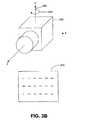
図1を参照すると、カメラ付き携帯電話100などの携帯娯楽用装置に備えられたカメラからの一連の画像のオプティカルフローを使用して、例えばゲームまたはアプリケーションを制御する手段としてのこの手持ち式装置の動きを検出するシステムが示されている。カメラ付き携帯電話100は、ユーザーがこの装置と対話できるように構成されているユーザーインタフェース110を有している。ユーザーインタフェース110は、例えば、表示インタフェース111と、キーパッド112と、マイクロフォン113と、スピーカー114とを有している。表示インタフェース111はユーザーに視覚的表示を提供する。その視覚的表示は、カメラ付き携帯電話の状態に関する情報又は、カメラ付き携帯電話上で動作するように構成されているゲームなどのアプリケーションに視覚的インタフェースを提供してよい。キーパッド112は、ユーザーがカメラ付き携帯電話へ入力するために作動させるボタンまたは押圧作動スイッチ群を有している。マイクロフォン113は、ユーザーからの音声による入力を受け付けるものであって、電話システムを用いてその音声入力を他の装置に送信するか又は、ユーザーの音声入力に基づいてユーザー入力を特定するように構成されていてもよい。スピーカー114は、ユーザーへの音声出力を生成するものであって、電話システムを介する通信の音声出力を生成するか又は、カメラ付き携帯電話の状態に関する情報を示す音声出力を生成する(例えば、ユーザー入力の受け付けを示す音を生成する)ように構成されていてもよい。プロセッサ(図示せず)は、ユーザーインタフェース110の各部分からの入力を受け付け、そのユーザー入力に基づいて機能または処理を実行し、ユーザー入力に適宜応答して表示ディスプレイ111に画像を映し、および/またはスピーカー114から音を生成するように構成されている。 Referring to FIG. 1, an optical flow of a series of images from a camera provided in a portable entertainment device, such as a
カメラ付き携帯電話100はまた、カメラ120を有している。カメラ120は、画像の焦点を合わせるためのレンズ121を有しており、レンズ121によって焦点が合わされた画像のデジタル表現を捕捉することができる。図1ではカメラ120はカメラ付き携帯電話100の上部にあってユーザーが表示インタフェース111を見ているときは、ユーザーに面するようになっているが、カメラ120は様々な場所および方向でカメラ付き携帯電話に配置されていてもよい。例えば、カメラ120は、カメラ付き携帯電話100の上部に位置し、ユーザーが表示インタフェース111を見ているときユーザーと向き合わないようになっていてもよい。カメラ120は、カメラ付き携帯電話100が動いている間、時間の経過と共に一連の画像を捕捉するように構成されていてもよい。プロセッサ(図示せず)が一連の画像を受け付けて、カメラ付き携帯電話100の動きの様子を検出するために一連の画像に対して処理を実行してもよい。プロセッサは、検出した動きに基づいて、検出したカメラ付き携帯電話100の動きに対応するアプリケーションへのユーザー入力を決定してよい。例えば、プロセッサが、ユーザーがカメラ付き携帯電話100を左に回転させたことを検出した場合、プロセッサは、ユーザーがある特定の行動を取ることを望んでいると決定してもよい。また、プロセッサが、ユーザーはカメラ付き携帯電話100を右に回転させたことを検出した場合、プロセッサは、ユーザーがある特定の行動を取ることを望んでいないと決定してもよい。他の実施形態では、プロセッサは、カメラ付き携帯電話100上で動作するゲームへのユーザー入力として、検出した動きを使用してもよい。例えば、カメラ付き携帯電話100を左に回転させると、ゲームで表示された物体を左に移動させ、カメラ付き携帯電話100を右に回転させると、ゲームで表示された物体を右に移動させる。 The camera-equipped
カメラが動いている間に捕捉された画像に基づいてカメラの動きの様子を検出するためにカメラ付き携帯電話100のプロセッサが使用する一つの技法が、オプティカルフローとして知られている。オプティカルフローとは、一連の画像の中の特徴の見かけの相対速度を指す。一連の画像を単一のカメラで捕捉して、特別なカメラハードウェアまたはキャリブレーション無しでオプティカルフローを使用することができる。従来、オプティカルフローは、画像シーケンスの時間補間(動画でフレームを挿入すること)、三次元物体再現調査などの用途に使用される。 One technique used by the camera
カメラの動きを検出するために、プロセッサが一連の画像の中で静的特徴群を特定し比較してもよい。カメラが動く間、画像内の特徴の位置はその動きに応答して変化する。特徴の速度をフローベクトルとして表現してもよい。特徴速度のセットをフロー場と呼ぶ。速度はカメラに対して相対的なものである。他の文献では、動きベクトルと動き場という用語がよく使用される。しかし、「動きベクトル」と「動き場」という用語の使用は、画像シーケンス内の特徴の速度が直接その物体の動きに対応し、カメラは静止していると仮定されることを意味する場合がある(本目的にとっては不必要)。 To detect camera movement, the processor may identify and compare static features in a series of images. While the camera moves, the position of the feature in the image changes in response to the movement. The speed of the feature may be expressed as a flow vector. A set of feature speeds is called a flow field. Speed is relative to the camera. In other documents, the terms motion vector and motion field are often used. However, the use of the terms “motion vector” and “motion field” may mean that the speed of a feature in the image sequence directly corresponds to the motion of the object and the camera is assumed to be stationary. Yes (unnecessary for this purpose).
オプティカルフローはカメラに対して相対的なものであるため、カメラの動きは、カメラ視界における特徴の見かけの速度となる。特徴は静止していてもよい、つまり木のように物理的位置が変化しなくてもよい。逆に、特徴は、動的すなわち動いていてもよい(例えば車)。カメラの動きを推定するために、一連の画像内の静的特徴の見かけの動きを利用する。カメラの動きは、カメラの視界中の特徴の見かけの速度から算出することができる。また、広く分布した疎らな特徴群のセットが、カメラの動きを推定するのに十分である。 Since the optical flow is relative to the camera, the camera movement is the apparent speed of the feature in the camera view. The feature may be stationary, that is, the physical position may not change like a tree. Conversely, a feature may be dynamic or moving (eg, a car). To estimate camera motion, we use the apparent motion of static features in a series of images. The movement of the camera can be calculated from the apparent speed of the feature in the camera's field of view. Also, a widely distributed sparse feature set is sufficient to estimate camera motion.
捕捉された画像を基にしてカメラの動きの様子を検出することができる様々な動き推定技法を使用してもよいが、既存のオプティカルフローシステムは一般的に計算コストが高く、故に現在の一般消費者向け手持ち式装置には不適切である。一般消費者向け手持ち式装置は、広範囲の種類の計算を実行できる汎用プロセッサを有している。しかし、ビデオフレームごとに実行できる計算の数は限られている。 Various motion estimation techniques that can detect camera motion based on captured images may be used, but existing optical flow systems are generally computationally expensive and hence current general Not suitable for consumer handheld devices. General consumer handheld devices have a general purpose processor capable of performing a wide variety of calculations. However, the number of calculations that can be performed per video frame is limited.
既存のオプティカルフローシステムは一般的に、密なフロー場の生成することを試みる。カメラの動きは6自由度で表現できる(例えば、X、Y、Z軸に沿った平行移動と、X、Y、Z軸の周りの回転)。しかし、意図する用途では、動きはもっと少ない自由度で近似できる。一つの実施形態では、ある特定の自由度における動きは無視できると仮定しその自由度における動きを無視することによって、カメラの動きを近似してよい。例えば、カメラの動きは、Z軸の周りの回転とX軸、Y軸、Z軸に沿った平行移動は無視し、X軸とY軸の周りのカメラの回転を記述することによって近似してもよい。よって、プロセッサはカメラの動きを推定するために密なフロー場を生成してもよいが、広く分布した疎らな特徴群のセットがカメラの動きを推定するのに十分である。広く分布した疎らな特徴セットについて、例えば図7を参照して後述する。 Existing optical flow systems generally attempt to create a dense flow field. The movement of the camera can be expressed with six degrees of freedom (for example, translation along the X, Y, and Z axes and rotation around the X, Y, and Z axes). However, in the intended application, the movement can be approximated with less freedom. In one embodiment, camera motion may be approximated by assuming that motion at a particular degree of freedom is negligible and ignoring motion at that degree of freedom. For example, camera motion can be approximated by describing camera rotation around the X and Y axes, ignoring rotation around the Z axis and translation along the X, Y, and Z axes. Also good. Thus, the processor may generate a dense flow field to estimate camera motion, but a widely distributed set of sparse features is sufficient to estimate camera motion. A sparse feature set that is widely distributed will be described later with reference to FIG.
特徴群を追跡するとき、平行移動無しのカメラ視野の回転(パンすること及び傾けること)は、フローベクトルが三次元場面形状(奥行き)から独立したオプティカルフローを生成する。これについては、以下で説明する図3A〜図3Cに例示されている。カメラが回転している静止した場面では、カメラが動くにつれて特徴が他の物体によって隠蔽されたり現れたりすることはない。特徴は、カメラの視野に入ったり出たりすることで現れたり消えたりするだけである。例えば、ある人が、物体の背後に何があるのか知るためにその物体の背後を見たいとする。その人は、その物体の向こう側を見るために傾くかまたは移動する(例えば平行移動)必要があり、単に自分の目を動かす(例えば回転運動)だけでその物体の向こう側を見ることはできない。 When tracking feature groups, rotation (panning and tilting) of the camera field without translation produces an optical flow whose flow vector is independent of the 3D scene shape (depth). This is illustrated in FIGS. 3A-3C described below. In a stationary scene where the camera is rotating, features are not hidden or revealed by other objects as the camera moves. The feature only appears and disappears as it enters and leaves the camera's field of view. For example, a person wants to look behind an object to see what is behind the object. The person needs to tilt or move (eg, translate) to see the other side of the object, and can't see the other side of the object simply by moving his eyes (eg, rotational movement) .
図2〜図4は、カメラの可能な動きと、その動きによって生成されるオプティカルフローベクトル及びオプティカルフロー場の例を示している。 2 to 4 show examples of possible camera movements and optical flow vectors and optical flow fields generated by the movements.
図2を参照すると、一連の画像を捕捉できるカメラ200が、カメラの動きを定義するための軸システムとの関係で示されている。特に、カメラの回転を3自由度について測定する。例えば回転を、X軸210と、Y軸220と、Z軸230に関して測定する。各軸の周りの回転の測定結果は、カメラの回転を完全に記述する可能性がある。カメラの動きの様子を定義したこの軸システムに関して説明する。次の例では、オプティカルフローベクトルは、紙面の上から見下ろすカメラ200とその紙面上の撮像物体に基づいて決定される。 Referring to FIG. 2, a
図3Aを参照すると、ベクトル310で示すようにX軸210を軸に回転するカメラ200が図示されている。静止した場面では、フローベクトルは平行でありX軸210の周りの回転と同じ大きさとなる傾向にある。カメラ200がX軸210の周りを回転することによって生成されるオプティカルフローベクトルが、オプティカルフロー場320に示されている。カメラ200がX軸210の周りをベクトル310で示す方向に回転すると、一連の画像で捕捉された静止した物体は、オプティカルフロー場320に示すオプティカルフローベクトルで示す方向に動いているように見える。具体的には、カメラ200が紙面の上方に向かって上方にX軸210の周りを回転し、同時にカメラ200が一連の画像を捕捉する場合、一連の画像内の静止した物体は、時間的に後の方に撮影された画像の中では画像の下部に近づいて現れ、その結果、紙面の下部の方を指すフローベクトルが生成される。算出されたオプティカルフロー場320に基づいて、X軸210の周りの回転を検出できる可能性がある。 Referring to FIG. 3A, a
図3Bを参照すると、Y軸220の周りを回転するカメラ200が図示されている。静止した場面では、フローベクトルは平行でありY軸220の周りの回転と同じ大きさとなる傾向にある。カメラ200のY軸220の周りの回転から生成されるオプティカルフローベクトルが、オプティカルフロー場340に示されている。カメラ200がY軸220の周りをベクトル330で示す方向に回転すると、一連の画像で捕捉された静止物体は、オプティカルフロー場340に示すオプティカルフローベクトルで示す方向に動いているように見える。具体的には、カメラ200がY軸220の周りを紙面の右側に向かって回転し、同時にカメラ200が一連の画像を捕捉する場合、その一連の画像内の静止した物体は右から左へと移動するように見える。すなわち、時間的に後の方に撮影された画像の中では、その静止した物体は画像の左側に近づいて現れ、その結果、紙面の左側の方を指すフローベクトルが生成される。算出されたオプティカルフロー場340に基づいて、Y軸220の周りの回転を検出できる可能性がある。 Referring to FIG. 3B, a
図3Cを参照すると、Z軸230の周りに回転するカメラ200が図示されている。静止した場面では、Z軸230の周りの回転の場合、フローベクトルはカメラ視界の中心点を中心とする円の接線方向を向き、その半径に比例する大きさを持つ傾向にある。カメラ200のZ軸230の周りの回転から生成されるオプティカルフローベクトルがオプティカルフロー場360に示されている。カメラ200がベクトル350で示す反時計回りにZ軸230の周りを回転する時、一連の画像で捕捉される静止した物体は、オプティカルフロー場360に示すオプティカルフローベクトルで示すように時計回りに動いているように見える。従って、ベクトルの略円形のオプティカルフロー場360が得られる。算出されたオプティカルフロー場360に基づいて、Z軸230の周りの回転を検出できる可能性がある。 Referring to FIG. 3C, a
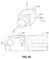
図4Aを参照すると、ベクトル410が示す方向にX軸210に沿って平行移動するカメラ200が図示されている。カメラの視野の平行移動は、フローベクトルが三次元場面形状(奥行き)に依存するオプティカルフローを生成する。カメラが平行移動している静止した場面では、フローベクトルの大きさはカメラ200から物体までの距離すなわち奥行きに依存し、カメラにより近い物体によって特徴が隠されたり現れたりすることがある。カメラが画像420を撮像しながらX軸方向410へ平行移動することによって生成されるオプティカルフローベクトルがオプティカルフロー場430に示されている。カメラ200がX軸方向410に沿って左へ平行移動すると、一連の画像で捕捉された静止物体(例えば、場面420における木および山)は、オプティカルフロー場430に示すオプティカルフローベクトルで示す方向に右へ移動するように見える。オプティカルフロー場430内のフローベクトルの大きさの差異によって示されるように、カメラ200に近い物体はカメラ200からより遠くの物体よりも長い距離を動くように見える。その結果、平行移動の場合、フローベクトルの長さは、撮像されている物体のカメラ200からの奥行きに依存する。例えば、木440がカメラに最も近い物体であるので、木440を表すフローベクトルは最大の大きさを持っている。算出されたオプティカルフロー場430に基づいて、X軸210に沿った平行移動を検出できる可能性がある。 Referring to FIG. 4A, a
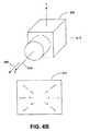
図4Bを参照すると、ベクトル450が示す方向にZ軸230に沿って平行移動するカメラ200が図示されている。Z軸方向450へのカメラの平行移動によって生成されるオプティカルフローベクトルがオプティカルフロー場460に示されている。カメラ200がZ軸方向450に沿って平行移動すると、一連の画像で捕捉された静止物体は、オプティカルフロー場460に示すオプティカルフローベクトルが示す方向に移動するように見える。具体的には、カメラがZ軸方向450に沿って撮像している物体に向かって前方に移動し、同時にカメラ200が一連の画像を捕捉する場合、一連の画像内の静止物体は画像の中心から延びる放射状の線に沿って外側に移動するように見える。従って、画像の中心から放射状に外側に向かって延びるフローベクトルのオプティカルフロー場460が得られる。算出されたオプティカルフロー場460に基づいて、Z軸230に沿った平行移動を検出できる可能性がある。 Referring to FIG. 4B, a
図示はしていないが、カメラ200のY軸220に沿った平行移動によって、フローベクトルがY軸220と平行である以外は図4Aに示すものと類似のオプティカルフロー場が生成される。 Although not shown, an optical flow field similar to that shown in FIG. 4A is generated by translation of the
図5A〜図5Fは、ユーザーが自分の手を使って動いているモバイルカメラに与える動きの例を示している。なお、図5A及び図5Bは、その下面にカメラ520を有している携帯電話510を例示している。携帯電話510を保持するユーザーは、携帯電話510とカメラ520とのX軸の周りの回転を発生させるために、例えば自分の手首を後方530に曲げる(図5C)、または前方540に伸ばす(図5D)。自分の手首を後方530に曲げる(図5C)ユーザーの動きは、図3Aに示すオプティカルフロー場320を生成する可能性のある一方向のX軸の周りのユーザー動きの一例である。 FIG. 5A to FIG. 5F show examples of movements that a user gives to a mobile camera that is moving using his / her hand. 5A and 5B illustrate a
また、携帯電話510を保持するユーザーは、携帯電話510とカメラ520とのY軸の周りの回転を発生させるために、例えば自分の手首を時計回り550に(図5E)または反時計回り560に(図5F)ひねる。時計回り550(図5E)に自分の手首をひねるユーザーの動きは、図3Bに示すオプティカルフロー場340を生成する可能性のある一方向のY軸の周りのユーザー動きの一例である。ユーザーが、例えば図5C〜図5Fに示す動きをすることで、アプリケーションのユーザーインタフェースを制御するユーザー入力を生成する検出可能な動きをカメラに与えてもよい。 In addition, the user holding the
図6は、装置の動きの様子を検出してアプリケーションへのユーザー入力を特定するための処理600を示すフローチャートである。一つの実施形態では、カメラが付いた携帯娯楽用装置(例えば、カメラ付き携帯電話100、PDA、その他のカメラが備えられたモバイル装置)のプロセッサが処理600を実行してもよく、また、携帯娯楽用装置上で動作するゲームまたはアプリケーションを制御するために、カメラ視野の回転の測定結果を使用してもよい。傾きセンサーと類似の入力を提供するために、回転の測定結果を使用してもよい。また、傾きの方向と大きさの両方を測定できるので、「アナログ」制御を行ってもよい。アナログ制御は、より細かな制御を可能にし、ゲームプレイの多くの方式にとって「デジタル」制御よりも好ましい。 FIG. 6 is a flowchart illustrating a
図6に示す処理600の実行において、動いているモバイルカメラが画像を捕捉する(610)。画像の捕捉(610)は、例えば、カメラが動いている間、ある時間に亘って一連の画像のデジタル表現を捕捉することを含んでもよい。 In the execution of
プロセッサは、捕捉された画像に基づいてカメラの動きの様子を検出する(620)。プロセッサは、例えば、最も新しく捕捉した画像を時間的にそれより前に捕捉した画像と比較して、一連の画像中の静的特徴の位置の変化を検出しカメラの動きを推定してもよい。プロセッサは前述のオプティカルフロー処理を使用してもよい。動きの様子の検出620は、図7に関連してより詳細に説明する。 The processor detects camera motion based on the captured image (620). The processor may, for example, compare the most recently captured image with a previously captured image in time to detect changes in the position of static features in the sequence of images and estimate camera motion. . The processor may use the optical flow processing described above.
さらに、アプリケーションへのユーザーインタフェースがインタフェース装置上に提供される(630)。ユーザーインタフェースは、モバイルカメラとは別れていてもよいし(例えば無線通信を利用する)、またはモバイルカメラを含む装置に物理的に結合されているかまたは一体化されていてもよい(例えば、カメラ付き携帯電話100に一体化された表示インタフェース111)。ユーザーインタフェースは、ユーザーが対話する可能性のあるゲームなどのアプリケーションのための視覚的表示を含んでもよい。ユーザーインタフェースはまた、ユーザー入力に応答して音声を生成するように構成されたスピーカーを含んでもよい。例えば、ユーザーインタフェースは、ある動作を起動する動きを受け付けたことを示す音声を生成するように構成されたスピーカーを含んでもよい。 In addition, a user interface to the application is provided on the interface device (630). The user interface may be separate from the mobile camera (eg, utilizing wireless communication), or may be physically coupled to or integrated with a device that includes the mobile camera (eg, with a camera) A
検出したカメラの動きに基づいてアプリケーションへのユーザー入力を特定する(640)。カメラの動きに対応して自動的にユーザー入力を特定してもよい。一つの実施形態では、アプリケーションが、「感度」を調節するためにカメラの動きおよび位置に係数を掛けてもよい。この係数は、ユーザーによってプログラムされるか、または選択されてもよい。「感度」は、例えばゲームの仮想環境におけるキャラクタの動きなどのユーザー入力を行うために、ユーザーがどれだけその装置を傾けるかまたは動かす必要があるかを決定する。例えば、ユーザー入力は、カメラの動きが「感度」のレベルを満たすのに十分大きいときのみに検出され特定されてもよい(つまり、小さな重要でない動きは無視されユーザー入力として特定されないことがある)。「感度」を利用する場合、現実世界での位置は通常必要なく計算されない。ここで、現実世界での位置とは、インチ、センチメートル、角度などの単位で測定された物理的世界での装置の位置を指す(例えば、25°回転され東に30センチメートル移動された装置)。仮想世界での位置とは、例えば仮想のキャラクタおよび物体を含むゲームなどの仮想環境における位置を指す(例えば、仮想環境において3ブロック移動させられた仮想キャラクタ)。「感度」を使用するときは、例えばピクセル単位で検出されたカメラの動きを「感度」係数と比較するか、または「感度」係数を掛けて、仮想環境への入力または動きを生成する。その入力または動きは仮想環境に関するものであるため、カメラの現実世界での位置は必要ではない。 A user input to the application is identified based on the detected camera movement (640). User input may be automatically identified in response to camera movement. In one embodiment, the application may multiply the camera movement and position by a factor to adjust the “sensitivity”. This factor may be programmed or selected by the user. “Sensitivity” determines how much the user needs to tilt or move the device in order to make user input, such as movement of characters in the virtual environment of the game. For example, user input may only be detected and identified when the camera movement is large enough to meet the “sensitivity” level (ie, small unimportant movement may be ignored and not identified as user input). . When using “sensitivity”, real-world location is usually not needed and not calculated. Here, the position in the real world refers to the position of the device in the physical world measured in units of inches, centimeters, angles, etc. (for example, a device rotated by 25 ° and moved 30 cm to the east) ). The position in the virtual world refers to a position in a virtual environment such as a game including a virtual character and an object (for example, a virtual character moved by three blocks in the virtual environment). When using “sensitivity”, for example, camera motion detected in pixels is compared to a “sensitivity” factor or multiplied by a “sensitivity” factor to generate an input or motion to the virtual environment. Since the input or movement is related to the virtual environment, the real world position of the camera is not necessary.
一つの例では、アプリケーションが、傾きセンサー機能を模倣するためにカメラの向きを使用してもよい。傾きセンサー機能を、ボールが転がる面の傾きをシミュレートすることを含む、ゲームにおけるボールの制御に使用してもよい。別の例では、アプリケーションが、操縦機能を模倣するためにカメラの向きを使用してもよい。操縦機能を、乗り物(例えば、自動車、オートバイ、飛行機、船、サーフボード、スノーボード、スケートボード、ホバーボード、宇宙船)を制御するのに使用してもよい。操縦機能は、操縦方向、ピッチ、ヨー、ロールのうち一つ以上の制御を含んでよい。さらに別の実施形態では、アプリケーションが、照準合わせ機能(狙いを定める)機能を模倣するためにカメラの向きを使用してもよい。照準を合わせるまたは狙いを定める機能を、仮想の武器を制御するのに使用してもよい(ライフルを向けるなど)。照準合わせ(狙いを定める)機能は通常、2自由度を含む。さらに、アプリケーションは、後述するように動く物体として分類された特徴群のサブセットを使用してもよい。このサブセットを、照準合わせ(狙いを定める)アプリケーションを補強するために使用してもよい(例えば、動く物体または特徴をターゲットとして指定し、そのゲームの目的が、動く物体または特徴が画面の中央に表示された十字線に位置するようにその装置を向けることであってもよい)。アプリケーションはまた、例えば、絶対位置決め機能を模倣するためにカメラの向きを使用してもよい。ナビゲーションの用途(例えば、店またはショッピングモールなどの環境においてユーザーをナビゲートするために現実世界環境におけるユーザーの位置を追跡する)、または迷路ゲーム(例えば、ユーザーが、現実世界で歩き回ることによって仮想迷路を歩く)において、絶対位置決め機能を使用してもよい。要求される動きは、手によって実行される動きであってもよいし、または環境においてユーザーが歩き回る動きであってもよい。 In one example, the application may use the camera orientation to mimic the tilt sensor function. The tilt sensor function may be used to control the ball in a game, including simulating the tilt of the surface on which the ball rolls. In another example, an application may use the camera orientation to mimic steering functions. Maneuvering functions may be used to control vehicles (eg, cars, motorcycles, airplanes, ships, surfboards, snowboards, skateboards, hoverboards, spacecraft). The steering function may include one or more controls of steering direction, pitch, yaw, and roll. In yet another embodiment, the application may use the camera orientation to mimic the aiming function. Aiming or aiming functions may be used to control virtual weapons (such as aiming a rifle). The aiming function typically includes two degrees of freedom. In addition, the application may use a subset of features grouped as moving objects as described below. This subset may be used to augment an aiming application (for example, specifying a moving object or feature as a target and the goal of the game is to move the object or feature to the center of the screen) You may point the device so that it is positioned on the displayed crosshair). The application may also use the camera orientation, for example, to mimic an absolute positioning function. Navigation applications (eg, tracking a user's location in a real-world environment to navigate the user in an environment such as a store or shopping mall), or a maze game (eg, a virtual maze by the user walking around in the real world) The absolute positioning function may be used. The required movement may be a movement performed by the hand or a movement of the user walking around in the environment.
別の実施形態では、アプリケーションが、アニメキャラクタ(例えば、ボブルヘッドやマリオネット)を制御するためにカメラの向きを使用してもよい。傾きの瞬間的な大きさおよび方向をそのキャラクタの動きに変換してもよい。キャラクタの関節で結合された各部分はシミュレートされた質量を与えられてもよい。その場合、検出された動きを与えられた各部分の動きの大きさは、その質量に反比例する。さらに、キャラクタの関節で結合された各部分は、所定の共振周波数を持つシミュレートされたばねによって相互に連結されていてもよい。 In another embodiment, the application may use the camera orientation to control an animated character (eg, bobblehead or marionette). The instantaneous magnitude and direction of the tilt may be converted into the movement of the character. Each part connected at the character's joint may be given a simulated mass. In that case, the magnitude of the motion of each part given the detected motion is inversely proportional to its mass. Further, the parts connected by the joints of the character may be connected to each other by a simulated spring having a predetermined resonance frequency.
また、アプリケーションは、粒子シミュレーションアプリケーション(例えば、スノーグローブまたはサンドアート)において粒子を制御するのにカメラの向きを使用してもよい。傾きの瞬間的な大きさおよび方向は、粒子の数および/またはそれらの運動エネルギーを決定してもよい。粒子はシミュレートされた重力によって引き寄せられてもよく、これによって粒子は仮想環境内で下に溜まる。仮想環境には画像または物体が含まれていてもよく、粒子はその物体の上に溜まる。このアプリケーションの一つの形態では、粒子は雪を表す。1つの選択肢として、アプリケーションは、電子グリーティングカード(例えばクリスマスカード)の形態で配布されてもよい。このアプリケーションの別の形態では、粒子群は様々な色で表示される(例えばサンドアート)。このアプリケーションでは、色付けされた粒子群が幾つかのパターンを形成して溜まってもよい。 The application may also use camera orientation to control particles in a particle simulation application (eg, snow globe or sand art). The instantaneous magnitude and direction of the tilt may determine the number of particles and / or their kinetic energy. The particles may be attracted by simulated gravity, which causes the particles to settle down in the virtual environment. The virtual environment may include an image or object, and the particles accumulate on the object. In one form of this application, the particles represent snow. As one option, the application may be distributed in the form of an electronic greeting card (eg, a Christmas card). In another form of this application, the particles are displayed in various colors (eg, sand art). In this application, the colored particles may accumulate in several patterns.
図7は、オプティカルフローを使用して動いているカメラの動きの様子を検出するための処理700を示すフローチャートである。密なフロー場アルゴリズムを使用してもよいが、カメラの動きは6自由度で表現することができ、意図するアプリケーションにおいてはより少ない自由度で近似できる。それゆえ、様々な自由度でカメラの動きを検知または推定するのに広く分布した疎らな特徴群のセットで十分であり、処理負荷を減らすために広く分布した疎らな特徴群のセットを使用してもよい。特定の実施形態では、処理負荷を減少させてリアルタイムで画像を捕捉し処理してもよい。 FIG. 7 is a flowchart illustrating a
一つの実施形態では、広く分布した疎らな特徴群のセットが、6自由度でカメラの動きを推定するのに十分である。疎らなオプティカルフローでは、画像中の視覚的に際立つ特徴についてのみフローベクトルが作成されてもよい。これらの特徴は、画像全体に亘って分散していてよい。広く分布した特徴群のセットでは、特徴が画像全体に亘って分布しており、画像の各領域に少なくとも一つの特徴が存在するようになっている(例えば、全ての特徴が画像の一角に塊として存在しているのとは違って)。ゆえに、画像の全領域における動きを記述するのに密フロー場は必要ではなく、特徴が広く分布していれば疎らなセットでも同じ役割を果たすことができる。 In one embodiment, a widely distributed set of sparse features is sufficient to estimate camera motion with 6 degrees of freedom. For sparse optical flows, flow vectors may be created only for visually distinctive features in the image. These features may be distributed throughout the image. In a widely distributed set of features, the features are distributed throughout the image so that there is at least one feature in each region of the image (for example, all features are clustered in one corner of the image). As it exists). Therefore, a dense flow field is not necessary to describe the motion in the entire region of the image, and a sparse set can play the same role if the features are widely distributed.
疎らなオプティカルフローでは、広く分布した特徴群のセットが必要である場合がある。例えば、Y軸の周りの回転(図3B)をX軸に沿った平行移動(図4A)と比較してみる。特徴の分布が十分でなければ、例えば画像の下部に沿った全てのフローベクトルが同じ方向と長さを有するので、X軸に沿った平行移動がY軸の周りの回転と区別できなくなる。 A sparse optical flow may require a widely distributed set of features. For example, compare rotation around the Y axis (FIG. 3B) with translation along the X axis (FIG. 4A). If the feature distribution is not sufficient, for example, all flow vectors along the bottom of the image have the same direction and length, so translation along the X axis is indistinguishable from rotation around the Y axis.
本発明の幾つかの実施形態では、6自由度よりも少ない自由度で動きを近似する。この場合、ある特定の自由度は無視できるものと仮定し無視する。自由度が減少すると広く分布した特徴群の必要性が軽減される。例えば、一つの実施形態では、X軸とY軸の周りのカメラの回転を記述し、Z軸の周りの回転とX軸、Y軸、Z軸に沿った平行移動とは無視することによってカメラの動きを近似してもよい。この仮定の下では、全ての特徴が画像の下部に沿って存在している前記の例におけるカメラの動きは、X軸に沿った平行移動は無視できるものと仮定しているので、Y軸の周りの回転の効果によるものであると考えることができる。 Some embodiments of the present invention approximate motion with less than 6 degrees of freedom. In this case, it is assumed that a certain degree of freedom is negligible. Decreasing the degree of freedom reduces the need for widely distributed feature groups. For example, in one embodiment, the camera is described by describing the rotation of the camera about the X and Y axes and ignoring the rotation about the Z axis and the translation along the X, Y, and Z axes. May be approximated. Under this assumption, the camera movement in the above example where all features are present along the bottom of the image assumes that translation along the X axis is negligible, so It can be considered that this is due to the effect of the surrounding rotation.
処置700は特徴を抽出すること(710)を含む。動くモバイルカメラから捕捉された一連の画像を分析する際には、そのカメラで捕捉された各画像に特徴抽出処理を適用する。特徴抽出処理は、任意の一つの画像から疎らな特徴群のセットを抽出するだけでよい。求められる特徴は通常、角および縁を含む。角や縁は、装置が操作される環境の多くで通常、見つけることができる。角および縁は動的な光レベルによって影響されにくい、これは装置が戸外で操作される場合に重要であることがある。さらに、角および縁などの特徴は、画像内で検出するのに比較的計算コストが安い。角および縁を抽出する方法は公知である。
特徴を抽出した後、処理700では、画像同士を比較して一つ以上の画像に共通な特徴を対応付ける(720)。例えば、フロー場算出処理では、現在のカメラ画像の特徴群と、前回のカメラ画像の対応する特徴群とを対応付ける。特徴を対応付けるために、現在のカメラ画像の各特徴を、前回のカメラ画像の特徴群のサブセットと比較する。このサブセットは、近接性と特徴の性質(例えば、角の向きおよびコントラスト)によって選択される。特定の実施形態では比較すべき特徴の数が少ないので、装置の計算負荷を最小にする。 After extracting the features, the
一つの実施形態では、前回のカメラ画像の特徴群の、現在の画像における位置を、前回のフロー場を使用して予測する(前回のフロー場がない最初のフレームは除く)。対応相手として可能性のあるもの全てについて、予測位置からの距離と特徴の性質の類似度と対応の特異性とによって作成されるスコアを基に、一対一の対応を選択する。スコアはスカラー値であり、信頼度を表している。一対一の対応を確認するために、可能性のあるペア群を、それらのスコアから、ペアのどちらかの特徴が関与する他の可能性のある対応関係のスコアに基づくペナルティを引き算したものに基づいてランク付けする。十分なスコア(信頼度)を有する対応相手をフロー場に追加する。スコア(信頼度)を後の使用のためにフローベクトルと共に記録する。 In one embodiment, the position of the feature group of the previous camera image in the current image is predicted using the previous flow field (except for the first frame without the previous flow field). One-to-one correspondence is selected based on the score created by the distance from the predicted position, the similarity of the characteristic of the feature, and the specificity of the correspondence for all possible correspondence partners. The score is a scalar value and represents the reliability. To confirm a one-to-one correspondence, the possible pairs are subtracted from their scores based on the scores of other possible correspondences involving either feature of the pair. Rank based on. Add a counterpart with a sufficient score (confidence) to the flow field. The score (confidence) is recorded along with the flow vector for later use.
他の実施形態では、計算の負荷を減らすために、特徴を対応付ける手順は、特徴の近くに位置するブロックを先ず分析するか、または最初は低解像度で特徴の対応付けを試みて対応が見つかるまでまたは最高の解像度で画像を比較するまで解像度を上げ続けることを含んでもよい。例えば、画像をデシメーションするピラミッド方法を適用してもよい。デシメーションでは、例えば画像をブロックに分割して各ブロックを代表する一つのピクセル値を生成する(例えば、ブロック内部のピクセルの平均値をとる)ことによって、画像の低解像度バージョン(ピラミッドのレベルと呼ぶ)を作成する。画像の低解像度バージョンは分析するピクセルが少なく探索する領域が小さいので、処理の負荷を減らすことが可能になる。低解像度で結果が得られたら、探索を制限するために低解像度で見つかった結果を利用して、より高い解像度で画像を分析してもよい。例えば、一つ以上の特定の低解像度領域で特徴の対応が見つかったら、それらの特定の低解像度の領域をより高い解像度で特徴を探すようにしてもよい。 In other embodiments, in order to reduce the computational burden, the procedure for associating features first analyzes blocks located near the feature, or first tries to match the features at low resolution until a correspondence is found. Or it may include continuing to increase the resolution until the images are compared at the highest resolution. For example, a pyramid method for decimating an image may be applied. Decimation, for example, divides an image into blocks and generates a single pixel value that represents each block (eg, taking an average value of the pixels inside the block), thereby calling a low-resolution version of the image (called the pyramid level). ). The low resolution version of the image has fewer pixels to analyze and the search area is small, thus reducing the processing load. Once results are obtained at a lower resolution, the results may be analyzed at a higher resolution using the results found at a lower resolution to limit the search. For example, if feature correspondence is found in one or more specific low-resolution areas, the specific low-resolution areas may be searched for features at a higher resolution.
特徴を対応付けた後、処理700では各特徴のフローベクトルを決定する(730)。一つの実施形態では、現在のカメラ画像での特徴の位置の、前回のカメラ画像でのその位置に対する変位を算出することによってフローベクトルを決定する。フローベクトルのセットによってフロー場が形成される。各フローベクトルは大きさと方向を有していてよい。対応付けられたペア群は、2つの関連するカメラ画像間で特徴の位置の全体的なパスを生成する。必要があればこのパスを格納して、より長い期間に亘ってオプティカルフロー(従ってカメラの動き)を算出できる。 After associating features, the
環境が静的であるという保証は無く、それ自体が動いている特徴によってカメラの動きを誤って推定してしまう可能性があるので、必要があれば特徴群を分けてもよい(740)。図7において工程740が破線で囲われていることが、工程740が選択可能であることを示している。一つの実施形態では、特徴を「セット」または「クラスタ」に分割して、環境の静的要素(つまり背景)に関連するフローベクトルのセットを生成する。例えば、カメラが動くのと同じ方向に鳥が画像を横切って飛んでいる場合、鳥を表す特徴は、静的特徴と同程度の大きさの変位を示さないか、または鳥がカメラよりも速く動いている場合、反対方向への変位を示すことがある。よって、鳥を表す特徴を分離して静的特徴に注目するようにすれば、カメラの動きのより正確な検出が可能になる場合がある。 Since there is no guarantee that the environment is static and there is a possibility that the motion of the camera may be erroneously estimated by the moving feature itself, the feature group may be divided if necessary (740). In FIG. 7, the fact that the
分離の一つの例では、環境の静的部分が、いずれの単一の動的(動いている)部分よりも大きい領域を構成していると仮定する。この仮定の下では、特徴群の最も重要なセットは環境の静的要素と関連する。ここで、「最も重要な」の計数は、特徴は均等に分散されていないので、特徴の数だけではなくこのセットによってカバーされた面積を含む。カメラの回転量を、この特徴群のセットを使用して推定する。特徴を分類して、静的な背景の一部である可能性が高いのか動いている物体である可能性が高いのかを示すタグを付けてもよい。このようなタグを、後のフレームにおいて特徴の分類を更新する際のヒントとして使用してもよい。 In one example of separation, assume that the static part of the environment constitutes a larger area than any single dynamic (moving) part. Under this assumption, the most important set of features is associated with the static elements of the environment. Here, the “most important” count includes not only the number of features but also the area covered by this set, since the features are not evenly distributed. The amount of camera rotation is estimated using this set of features. The features may be classified and tagged to indicate whether they are likely to be part of a static background or a moving object. Such a tag may be used as a hint when updating the feature classification in a later frame.
別の例では、Z軸の周りの回転は重要でないとし(つまり回転は、X軸およびY軸の周りのものに限定される)、またX軸、Y軸、Z軸に沿った平行移動を重要でないとすると、環境(つまり背景)の静的要素に関連する各フローベクトルは類似の方向と大きさとを有する傾向にある。例えば、図3Aおよび図3Bに示すように、X軸とY軸とだけの周りの回転は、ほぼ平行かつ同等の大きさである静的特徴のフローベクトルを生成する。動いている特徴は、静的特徴(例えば、静的特徴と判定された特徴)のフローベクトルと十分に平行ではないか、又は十分に同等の大きさではないフローベクトルを有する特徴を検出することによって、静的特徴から分けることができる。例えば、許容方向範囲(例えば、静的特徴のフローベクトルの方向から±5°)および許容大きさ範囲(例えば、静的特徴のフローベクトルの大きさから±5ピクセル)を、例えば静的特徴のフローベクトルの検出された方向および大きさに基づいて算出してもよい。ある特徴のフローベクトルの方向が許容方向範囲内でなければ、またはその大きさが許容大きさ範囲内でなければ、その特徴を動いている特徴として分離してもよい。 In another example, rotation about the Z axis is not important (ie, rotation is limited to those around the X and Y axes) and translation along the X, Y, and Z axes is If not important, each flow vector associated with a static element of the environment (ie, background) tends to have a similar direction and magnitude. For example, as shown in FIGS. 3A and 3B, rotation about only the X and Y axes produces a flow vector of static features that are approximately parallel and of equal magnitude. Detecting features whose moving features are not sufficiently parallel to the flow vector of static features (eg, features determined to be static features) or that have a flow vector that is not sufficiently large Can be separated from static features. For example, an allowable direction range (eg, ± 5 ° from the direction of the static feature flow vector) and an allowable size range (eg, ± 5 pixels from the size of the static feature flow vector) You may calculate based on the detected direction and magnitude | size of a flow vector. If the direction of the flow vector of a feature is not within the allowable direction range, or the size is not within the allowable size range, the feature may be separated as a moving feature.
計算能力が限られたシステムで使用する、動的特徴と静的特徴とに別ける好適な方法は、フローベクトルの方向と大きさの類似性を利用して最も重要な特徴群のセットを選択することである。この実施形態では、静的背景は通常、動いているいずれの物体よりも大きいので、最も重要な特徴群のセットは静的背景であると仮定される。他の実施形態では、最も重要な特徴群のセットは、既知の現実世界の基準物体であると仮定してもよい。基準物体の例は、カメラがユーザーに面する方向を向いている実施形態ではユーザーの顔である。使用した仮定にかかわらず、最も重要な特徴群のセットは、平行かつ同等の大きさを持ち画像の中の最大領域に広がり、および/または最も多い数の特徴を有する特徴群のセットを選択することによって、決定されてもよい。最も重要な特徴群のセットを決定したら、その最も重要な特徴群のセットのフローベクトルと平行ではないかまたは同じ大きさではないフローベクトルを有する特徴を取出すことによって、動いている特徴を分離してもよい。カメラの動きの追加の自由度(例えばZ軸の周りの回転)の推定は任意であり、追加の自由度を推定するかどうかは、手持ち式装置の利用できる計算能力によって決定してもよい。 The preferred method of separating dynamic and static features for use in systems with limited computational power uses the similarity of flow vector direction and magnitude to select the most important set of features. That is. In this embodiment, the static background is usually larger than any moving object, so it is assumed that the most important set of features is the static background. In other embodiments, the most important set of features may be assumed to be known real-world reference objects. An example of a reference object is the user's face in embodiments where the camera is facing the user. Regardless of the assumptions used, the most important set of features is selected to be the set of features that are parallel and of equal size, span the largest area in the image, and / or have the largest number of features. May be determined. Once the most important set of features has been determined, the moving features are separated by extracting features with flow vectors that are not parallel or not the same size as the flow vectors of the most important set of features. May be. Estimating additional degrees of freedom of camera movement (eg, rotation about the Z axis) is arbitrary, and whether to estimate additional degrees of freedom may be determined by the available computing power of the handheld device.
処理700は、カメラの動きを検出する(750)。カメラの動きは、一連の画像で対応付けられているが分けられていない各特徴のオプティカルフローベクトルを備えるオプティカルフロー場を使用して検出してもよい。カメラの動きを、オプティカルフローベクトルによって表されるカメラ視野内の特徴の見掛けの速度から算出してもよい。静的特徴のフローベクトルの大きさと方向はカメラの動きに関連しており、カメラの動きを推定するのに使用してもよい。
例えば、静止した場面では、カメラの回転は以下の式によって近似できる:
Vxi=Mx+Mz*Ri*cos(Thetai)
Vyi=My+Mz*Ri*sin(Thetai)
ここで、VxiとVyiは特徴iのフローベクトルの成分を表している。
Mx、My、Mzはカメラの回転量を表している。
RiとThetaiは、極座標における画像内の特徴の位置を表し、測定値から決定される。For example, in a stationary scene, the camera rotation can be approximated by the following formula:
Vxi = Mx + Mz * Ri * cos (Thetai)
Vyi = My + Mz * Ri * sin (Thetai)
Here, Vxi and Vyi represent the components of the flow vector of feature i.
Mx, My, and Mz represent camera rotation amounts.
Ri and Thetai represent the position of the feature in the image in polar coordinates and are determined from the measured values.
十分に分布した少数の特徴があれば、未知のMx、My、Mzを推定できる。検出された回転量(つまりVxiとVyi)は、アプリケーションを制御するために直接使用できるか、またはカメラとレンズの性質が分かっていれば現実世界の単位(°)に換算できる。 If there are a small number of well-distributed features, the unknown Mx, My, Mz can be estimated. The detected amount of rotation (ie Vxi and Vyi) can be used directly to control the application, or can be converted to real world units (°) if the camera and lens properties are known.
別の実施形態では、Z軸の周りの回転およびX軸、Y軸、Z軸に沿った平行移動は、ユーザーは通常Z軸の周りにカメラを回転させることはなくそしてユーザーは通常静止しているため、重要でないと仮定する。この実施形態では、静止した場面でのX軸およびY軸の周りのカメラの回転量は、単に、全ての特徴のフローベクトルの平均と推定できる。X軸およびY軸のみの周りの回転ではほぼ平行で同等の大きさのフローベクトルが生成されるため、全フローベクトルの平均が、全フローベクトルの比較を代表するものとなる。一つの例では、静止した場面でのX軸およびY軸の周りのカメラの回転量を、全ての特徴のフローベクトルの加重平均と推定してもよい。加重平均では、各フローベクトルの影響に信頼度スコアを掛け算する。結果として、高い信頼度を有するフローベクトル(例えば良好な対応関係)が、低い信頼度を有するフローベクトル(例えば劣っているかまたは疑わしい対応関係)よりも、結果に大きな影響を与える。 In another embodiment, rotation about the Z axis and translation along the X, Y, and Z axes does not normally cause the user to rotate the camera about the Z axis and the user is usually stationary. Suppose that it is not important. In this embodiment, the amount of camera rotation about the X and Y axes in a stationary scene can simply be estimated as the average of the flow vectors of all features. Rotating around only the X and Y axes produces flow vectors of approximately parallel and equivalent size, so the average of all flow vectors is representative of the comparison of all flow vectors. In one example, the amount of camera rotation about the X and Y axes in a stationary scene may be estimated as a weighted average of all feature flow vectors. In the weighted average, the influence of each flow vector is multiplied by the reliability score. As a result, flow vectors with high confidence (eg, good correspondence) have a greater impact on the results than flow vectors with low confidence (eg, poor or suspicious correspondence).
処理700は、必要があればカメラの累積した動きを算出する(760)。図7において工程760が破線で囲われていることが、この工程が選択可能であることを示している。累積した動きを、カメラの検出された動きを追跡することによって算出してもよい。一連のカメラ画像の累積した動きを、最初の位置に対するこの装置の位置を検出するために算出してもよい。しかし、比較的速く画像から画像へと誤差が増大する場合がある。
増大する誤差を低減するために、フロー場を算出する際に、特徴の全体的なパスを格納してもよい。最初の位置に対する特徴の変位を表す全体的な動きベクトルに、前述したカメラの動き技法を適用できる。これは、カメラの動きが限定的なものであって、特徴群のサブセットが追跡期間に亘ってカメラの視野内に留まる場合に特に有効であることがある。例えば、鉛筆の先端が画像の中の特徴であるとする。鉛筆の先端が画像の中に留まるような領域に亘ってカメラが動くとき、鉛筆の先端を表す特徴の元の位置を格納しておけば、その鉛筆の先端を表す特徴の現在の位置をその鉛筆の先端を表す特徴の元の位置と比較することによってカメラの累積した動きを算出してもよい。各パスは通常、多くのカメラフレームにわたるので、誤差の累積は、フレーム間で累積した動きを算出するよりも遅くなる。 To reduce the increasing error, the entire path of features may be stored when calculating the flow field. The camera motion technique described above can be applied to the overall motion vector representing the displacement of the feature relative to the initial position. This can be particularly useful when the camera movement is limited and a subset of the feature group remains in the camera's field of view over the tracking period. For example, assume that the tip of the pencil is a feature in the image. When the camera moves over an area where the tip of the pencil stays in the image, storing the original position of the feature that represents the tip of the pencil will store the current position of the feature that represents the tip of the pencil. The accumulated movement of the camera may be calculated by comparing with the original position of the feature representing the tip of the pencil. Since each pass typically spans many camera frames, error accumulation is slower than calculating accumulated motion between frames.
最初の画像以降、検出された全ての特徴を考えると、全体的な特徴パス群のセットに、追跡の全期間に亘って延びるパスが含まれているとは限らない。例えば、上述したように、物体(鉛筆の先端など)がカメラの視野から出てしまうこともある。しかし、全体的な特徴パス群のセットは、開始時(最初に検出された、又はカメラの視野に入った)と終了時(最後に検出された、又はカメラの視野から出た)が重なっている、分かれているが関連するパス群を含んでいる可能性が高い。(時間上)重なっているパスの組み合わせを、最初の位置に対して特徴群を累積的に位置付けするために使用できる。 Considering all the features detected after the first image, the set of overall feature paths does not necessarily include paths that extend over the entire period of tracking. For example, as described above, an object (such as the tip of a pencil) may come out of the field of view of the camera. However, the overall set of feature paths overlaps at the beginning (first detected or entered the camera field of view) and at the end (last detected or exited from the camera field of view). There is a high probability that it contains separate but related paths. A combination of (over time) overlapping paths can be used to position the feature group cumulatively relative to the initial position.
例えば、鉛筆の先端は画像の中の特徴であるが、鉛筆の消しゴムは画像の中に存在していないとする。カメラが動くと、鉛筆の先端を表す特徴が画像にわたって移動し、追跡される。その後の画像では鉛筆の消しゴムが視野に入り、鉛筆の先端と鉛筆の消しゴムの両方が画像の中で追跡された特徴となるようにカメラが動いたとする。さらにカメラが動くと、鉛筆の先端は画像から去り、鉛筆の消しゴムを表す特徴はまだ残って追跡されるとする。鉛筆の先端と鉛筆の消しゴムは同時に画像内に存在していた特徴であるので、プロセッサは、鉛筆の先端に対する鉛筆の消しゴムの相対的な位置を算出できる。よって、(1)鉛筆の消しゴムを表す特徴の現在位置と、(2)鉛筆の先端に対する鉛筆の消しゴムの相対位置と、(3)鉛筆の先端がカメラの視野から去る前の格納されたパスとを使用して、プロセッサが、消しゴムの完全なパスを決定してもよい。次に、消しゴムの完全なパスをプロセッサが使用して、カメラの累積した動きを追跡しカメラの最初の位置を特定してもよい。この技法を、鉛筆の消しゴムが画像から出るときにカメラの累積した動きを追跡し続けるために、追加の特徴で繰り返してもよい。このような関連しているが分かれている特徴パスを使用することによって、個々の特徴パスを使用するよりも、誤差の累積をかなり遅くすることができる。 For example, it is assumed that the tip of the pencil is a feature in the image, but the pencil eraser is not present in the image. As the camera moves, features representing the tip of the pencil move across the image and are tracked. In subsequent images, the pencil eraser enters the field of view, and the camera moves so that both the tip of the pencil and the pencil eraser have the characteristics tracked in the image. As the camera moves further, the tip of the pencil leaves the image, and the features representing the pencil eraser are still tracked. Since the tip of the pencil and the eraser of the pencil are features present in the image at the same time, the processor can calculate the relative position of the eraser of the pencil with respect to the tip of the pencil. Thus, (1) the current position of the feature representing the pencil eraser, (2) the relative position of the pencil eraser to the tip of the pencil, and (3) the stored path before the pencil tip leaves the field of view of the camera. , The processor may determine the complete path of the eraser. The complete eraser path may then be used by the processor to track the accumulated movement of the camera and determine the initial position of the camera. This technique may be repeated with additional features to keep track of the cumulative movement of the camera as the pencil eraser exits the image. By using such related but separate feature paths, error accumulation can be significantly slower than using individual feature paths.
処理700を使用して、例えば、カメラの動き、カメラの最初の位置に対する相対的な位置および/またはカメラの最初の方向に対する相対的な方向を、2から6の各自由度で算出してもよい。6未満の自由度でカメラの動きを推定する際には、6自由度のうちの一つ以上の動きが固定であると仮定する。例えば、ユーザーが一つの位置で起立または着席し、Z軸の周りにこの装置を回転させないと予想される場合、2自由度(X軸およびY軸の周りの回転)が適当である可能性がある。ユーザーが一つの位置で起立または着席すると予想される場合、3自由度(3つ全ての軸の周りの回転)が適当である可能性がある。ユーザーが歩き回ることが予想される場合、6自由度(3つ全ての軸の周りの回転および3つ全ての軸に沿った平行移動)が適当である可能性がある。アプリケーションが累積した位置算出のための最初の位置を、任意の時に、または、例えばセッション、ゲーム、レベルの開始時に、またはユーザーが要求した時にリセットしてもよい。
これらは画像に依存する単位で算出されるが、カメラレンズについての情報があれば、現実世界の単位(即ち、角度)に変換できる。画像に依存する単位は、カメラの画像のピクセルを使って表されることがあるが、現実世界の単位は、角度(回転について)と、インチまたはセンチメートル(平行移動について)で表されることがある。画像に依存する単位を現実世界の単位に変換する一つの方法は、単に、方向に、視野(つまり角度)/画像サイズ(つまりピクセル)を表す係数を掛け算する。 These are calculated in units that depend on the image, but if there is information about the camera lens, it can be converted to real world units (ie, angles). Image-dependent units may be represented using camera image pixels, while real-world units are expressed in angles (for rotation) and inches or centimeters (for translation) There is. One way to convert image dependent units to real world units is simply to multiply the direction by a factor representing field of view (ie angle) / image size (ie pixel).
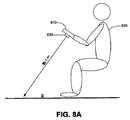
図8A〜図8Cは、例えば図6で示す処理600と図7に示す処理700とを実行するように構成されたプロセッサ(図示せず)を有するカメラ付き手持ち式装置810を操作するユーザーを例示している。プロセッサは、ゲームなどの表示インタフェースを持つアプリケーションを実行するように構成されていてもよい。 8A-8C illustrate a user operating a handheld device with
図8Aを参照すると、装置810が座っているユーザー820によって保持されている。携帯娯楽装置(例えばカメラ付き携帯電話)に備えられたカメラの場合、そのカメラの動きが、平行移動無しの純粋な回転であるとは限らない。しかし、その場面の物体がカメラから十分離れた位置にある場合、平行移動よりも回転の方が特徴のフローベクトルの大きさに大きな影響を与えるので、オプティカルフローに対する平行移動の影響はある種のアプリケーションにとっては重要ではない。図示の例では、装置810のカメラ830が、カメラから約1mの距離にある床に面している。このシナリオでは、1°のカメラ回転によって生成されるオプティカルフロー速度の大きさは、17cmのカメラ平行移動と同程度であることがある。このシナリオのユーザーは、意図的にカメラ付き携帯電話を傾けるが、数センチメートルを超えて電話を平行移動させる可能性は少ない。それゆえ、感知できるほどの誤差を生成するためにはユーザーは通常ではあり得ないほど長い距離にわたって装置を平行移動させる必要があるため、装置を回転させることによってゲームを制御するために必要な精度を求めて、平行移動の影響は無視でき、オプティカルフローは単純に回転の結果であると仮定できる。従って、ユーザー820は装置を回転させてカメラ付き手持ち式装置810で実行されるアプリケーションにユーザー入力を提供できる。 Referring to FIG. 8A, the
図8Bを参照すると、装置810が起立しているユーザー840によって保持されている。この例では、ユーザー840は、床に面している装置810のカメラ830を持って比較的静止した状態で起立している。座っているユーザーと同様に、床との距離はカメラの平行移動を無視できるほど十分に遠いものであり、ユーザー840はカメラ付き手持ち式装置810を回転させてアプリケーションへユーザー入力を提供できる。 Referring to FIG. 8B, the
図8Cを参照すると、カメラ付き手持ち式装置850が、起立しているユーザー860によって保持されている。この例では、カメラ付き手持ち式装置850のカメラ870はユーザーの顔に面している。カメラ870がユーザーの顔に向けられると、その顔がカメラ画像の大きな部分を占めるようになり、回転の測定値はユーザー860を基準とするので、ユーザー860は歩いたり動き回ったりしながらカメラ付き手持ち式装置850を操作できる。これは、ユーザー860が動く時、ユーザーの顔はカメラ付き手持ち式装置850に対して動かないためである。ユーザーの顔が静的背景にかわって最も重要な物体となるため、カメラ付き手持ち式装置850の動きはユーザー860を基準として測定される。このため、ユーザー860の歩行は装置の動きとして検知されず、ユーザー入力の検出には影響を及ぼさない。 Referring to FIG. 8C, a handheld device with
ゲームなどのアプリケーションのユーザーインタフェースを制御するためにユーザー入力を検出するというアプリケーションについて述べてきたが、これ以外のアプリケーションも可能である。具体的には、カメラが物理的に結合された装置の他の機能または特徴を制御するアプリケーションであってもよい。例えば、装置の動きが検知され、アラームが禁止になっていないときに装置の警報信号を起動する盗難防止のためのセキュリティアプリケーションを利用してもよい。また、ユーザーがカメラ付き携帯電話を自分の耳から離すように傾けた時その電話の音量を上げる音量制御アプリケーションを実現させてもよい。処理600および700と、その他の本願明細書に記載した様々な実施形態、特徴、技法は、主に、装置上で動作するオペレーティングシステムによってソフトウェアとして実行されてもよい。そのソフトウェアは、カメラからのデータと、装置に一体化されたコンピュータディスプレイ、テレビ、LCDなどの表示装置と協働する。ソフトウェアと一緒にまたはソフトウェアに代えてファームウェアおよびハードウェアを使用してもよい。 Although an application that detects user input to control the user interface of an application such as a game has been described, other applications are possible. Specifically, it may be an application that controls other functions or features of the device to which the camera is physically coupled. For example, a security application for theft prevention that activates a warning signal of the device when the movement of the device is detected and the alarm is not prohibited may be used. Also, a volume control application that increases the volume of the phone when the user tilts the camera-equipped mobile phone away from his / her ear may be realized.
本開示から明らかなように、本願明細書に記載された実施形態、特徴、技法と、これらの変形または組み合わせとは、例えば様々な装置上で動作するオペレーティングシステム、またはスタンドアローンのアプリケーションまたはユーティリティなどで実施されてよい。 As is apparent from this disclosure, the embodiments, features, techniques, and variations or combinations thereof described herein include, for example, an operating system running on various devices, or a stand-alone application or utility. May be implemented.
携帯電話、個人用デジタル補助装置(「PDA」)、その他のポータブル装置は、ユーザーインタフェースのサイズが通常は限定されていてこのような装置でユーザーインタフェースを制御することが通常は困難であるため、多数の実施形態を提供する。例えば、Blackberry装置、電子手帳、iPod装置またはその他のポータブル音楽プレイヤー、ポケットベルまたはその他の通信装置、ゲーム・通信および/またはデータ編集のための携帯またはポータブル電子装置などで実施できる。 Because mobile phones, personal digital assistants (“PDAs”), and other portable devices typically have limited user interface sizes, it is usually difficult to control the user interface with such devices, Numerous embodiments are provided. For example, it can be implemented on a Blackberry device, an electronic organizer, an iPod device or other portable music player, a pager or other communication device, a portable or portable electronic device for gaming / communication and / or data editing.
実施形態は、一つ以上の処理を実行するように構成された一つ以上の装置を有していてもよい。装置は、例えば、別個のまたは一体化されたハードウェア、ファームウェア、ソフトウェアを有していてもよい。これらの装置は、例えばマイクロプロセッサ、集積回路、プログラム可能な論理装置、ソフトウェアアプリケーションを内蔵する装置などの処理装置を一般的に指すプロセッサを有していてもよい。 Embodiments may include one or more devices configured to perform one or more processes. The device may have, for example, separate or integrated hardware, firmware, software. These devices may have a processor that generally refers to a processing device such as, for example, a microprocessor, an integrated circuit, a programmable logic device, or a device containing a software application.
実施形態はまた、一つ以上の処理を実行するための命令を含むコンピュータ読み取り可能な一つ以上の媒体を有する装置において実施されてもよい。コンピュータ読み取り可能な媒体は、例えばハードディスク、コンパクトディスケット、ランダム・アクセス・メモリ(「RAM」、リード・オンリー・メモリー(「ROM」)などの記憶装置を含む。コンピュータ読み取り可能な媒体はまた、例えばフォーマットされた電磁波符号化または送信命令群を含んでいてもよい。命令群は、例えばハードウェア、ファームウェア、ソフトウェア、又は電磁波の形態であってもよい。命令群は、例えばオペレーティングシステム、アプリケーション、またはこれらの組み合わせに含まれていてもよい。プロセッサは、例えば処理を実行するように構成された装置と、処理を実行するための命令を含むコンピュータ読み取り可能な媒体を有する装置との両方であってもよい。 Embodiments may also be implemented in an apparatus having one or more computer-readable media containing instructions for performing one or more processes. Computer readable media include, for example, storage devices such as hard disks, compact diskettes, random access memory (“RAM”, read only memory (“ROM”)), etc. Computer readable media can also be formatted, for example. For example, in the form of hardware, firmware, software, or electromagnetic waves, for example, an operating system, application, or these A processor may be, for example, both a device configured to perform a process and a device having a computer-readable medium containing instructions for performing the process. Good.
実施形態はまた、ソフトウェア・オブジェクトの形態で実現されてもよい。このようなオブジェクトは、様々なアプリケーションによってアクセスされるか、または様々なアプリケーションに組み込まれてもよい。 Embodiments may also be implemented in the form of software objects. Such objects may be accessed by various applications or incorporated into various applications.
いくつかの実施形態を説明したが、様々な変形が可能であることは理解されよう。例えば、異なる実施形態の各要素を組み合わせたり、追加したり、修正したり、取り除いたりして他の実施形態を実現してもよい。さらに、各種の技術を使用したり、組み合わせたり、修正したりして実施形態を実現してもよい。このような技術には、例えば様々なハードウェア、ソフトウェア、ファームウェア、一体化されたコンポーネント、別個のコンポーネント、処理装置、メモリまたは記憶装置、通信装置、レンズ、フィルタ、表示装置、投射装置などが含まれる。従って、他の実施形態も添付の請求項の範囲内である。 Although several embodiments have been described, it will be appreciated that various modifications are possible. For example, other embodiments may be realized by combining, adding, modifying, or removing elements of different embodiments. Furthermore, the embodiments may be realized by using, combining, or modifying various technologies. Such technologies include, for example, various hardware, software, firmware, integrated components, separate components, processing devices, memory or storage devices, communication devices, lenses, filters, display devices, projection devices, etc. It is. Accordingly, other embodiments are within the scope of the appended claims.
Claims (27)
Translated fromJapanese前記装置に配置された前記画像センサーによって捕捉した前記画像中に存在する静止した第1の特徴を識別する段階と、
前記装置に配置された前記画像センサーによって捕捉した前記画像中に存在する静止した第2の特徴を識別する段階と、
捕捉した前記画像内での前記第1の特徴と前記第2の特徴との間の距離の変化に基づいて、前記装置の奥行き方向の動きの様子を検出する段階と
を有し、
前記第2の特徴は、前記第1の特徴とは異なるものであり、前記第1の特徴から離れた位置にあり、
前記奥行き方向は、前記第1の特徴および前記第2の特徴に対して近づいたり遠ざかったりする移動の方向であることを特徴とする方法。Accessing an image captured by an image sensor located on the device;
Identifying a stationary first feature present in the image captured by the image sensor disposed on the device;
Identifying a stationary second feature present in the image captured by the image sensor located on the device;
Detecting the movement of the device in the depth direction based on a change in the distance between the first feature and the second feature in the captured image;
The second feature is different from the first feature and is located away from the first feature;
The depth direction is a direction of movement toward or away from the first feature and the second feature.
検出された前記装置の前記奥行き方向の動きに対応した態様で、ユーザーインタフェースに映される物体の移動を制御する段階を含むことを特徴とする請求項2に記載の方法。Identifying the user input to the application based on the detected behavior of the device in the depth direction;
3. The method of claim 2, comprising controlling movement of an object projected on a user interface in a manner corresponding to the detected depth movement of the device.
前記装置の前記奥行き方向の動きの距離を算出する段階を含み、
検出された前記装置の前記奥行き方向の動きに対応した態様で、ユーザーインタフェースに映される物体の移動を制御する前記段階が、
前記ユーザーインタフェースに映される前記物体を、算出された前記装置の前記奥行き方向の動きの前記距離に対応した前記ユーザーインタフェース内の距離だけ方向付け、回転、またはナビゲートするように制御する段階をさらに含むことを特徴とする請求項5に記載の方法。Detecting the state of movement of the device in the depth direction,
Calculating a distance of movement of the device in the depth direction,
Controlling the movement of an object projected on a user interface in a manner corresponding to the detected movement of the device in the depth direction;
Controlling the object projected on the user interface to direct, rotate, or navigate the calculated distance of the device in the user interface corresponding to the distance of the depth movement. The method of claim 5, further comprising:
前記装置の平行移動量を算出する段階を含み、
検出された前記装置の前記奥行き方向の動きに対応した態様で、ユーザーインタフェースに映される物体の移動を制御する前記段階が、
前記ユーザーインタフェースに映される前記物体を、算出された前記装置の前記平行移動量に対応した態様で、前記ユーザーインタフェース内で方向付け、回転、またはナビゲートするように制御する段階をさらに含むことを特徴とする請求項5に記載の方法。Detecting the state of movement of the device in the depth direction,
Calculating a translation amount of the device;
Controlling the movement of an object projected on a user interface in a manner corresponding to the detected movement of the device in the depth direction;
Further comprising controlling the object projected on the user interface to be directed, rotated, or navigated in the user interface in a manner corresponding to the calculated amount of translation of the device. The method according to claim 5, wherein:
前記モバイル装置に配置された画像センサーと、
少なくとも1つのプロセッサと
を具備し、
前記少なくとも1つのプロセッサは、
前記モバイル装置に配置された前記画像センサーによって補足した画像にアクセスする手順と、
前記モバイル装置に配置された前記画像センサーによって捕捉した前記画像中に存在する静止した第1の特徴を識別する手順と、
前記モバイル装置に配置された前記画像センサーによって捕捉した前記画像中に存在する静止した第2の特徴を識別する手順と、
捕捉した前記画像内での前記第1の特徴と前記第2の特徴との間の距離の変化に基づいて、前記モバイル装置の奥行き方向の動きの様子を検出する手順と
を実行するように構成され、
前記第2の特徴は、前記第1の特徴とは異なるものであり、前記第1の特徴から離れた位置にあり、
前記奥行き方向は、前記第1の特徴および前記第2の特徴に対して近づいたり遠ざかったりする移動の方向であることを特徴とするシステム。A mobile device;
An image sensor disposed on the mobile device;
At least one processor;
The at least one processor comprises:
Accessing an image supplemented by the image sensor located on the mobile device;
Identifying a stationary first feature present in the image captured by the image sensor disposed on the mobile device;
Identifying a stationary second feature present in the image captured by the image sensor located on the mobile device;
A procedure for detecting a state of movement of the mobile device in the depth direction based on a change in a distance between the first feature and the second feature in the captured image. And
The second feature is different from the first feature and is located away from the first feature;
The depth direction is a direction of movement that approaches or moves away from the first feature and the second feature.
検出された前記モバイル装置の前記奥行き方向の動きの様子に基づいて、アプリケーションに対するユーザー入力を特定する手順をさらに実行するように構成されることを特徴とする請求項9に記載のシステム。The at least one processor comprises:
The system of claim 9, wherein the system is further configured to further determine a user input to the application based on the detected behavior of the mobile device in the depth direction.
検出された前記モバイル装置の前記奥行き方向の動きに対応する態様で、ユーザーインタフェースに映される物体の移動を制御する手順を含むことを特徴とする請求項10に記載のシステム。The step of identifying user input to an application based on the detected movement of the mobile device in the depth direction;
The system according to claim 10, further comprising a step of controlling movement of an object projected on a user interface in a manner corresponding to the detected movement of the mobile device in the depth direction.
前記モバイル装置の前記奥行き方向の動きの距離を算出する手順を含み、
検出された前記モバイル装置の前記奥行き方向の動きに対応する態様で、ユーザーインタフェースに映される物体の移動を制御する前記手順が、
前記ユーザーインタフェースに映される前記物体を、算出された前記モバイル装置の前記奥行き方向の動きの前記距離に対応した前記ユーザーインタフェース内の距離だけ方向付け、回転、またはナビゲートするように制御する手順を含むことを特徴とする請求項11に記載のシステム。The procedure for detecting the movement of the mobile device in the depth direction comprises:
Calculating a distance of the movement in the depth direction of the mobile device,
The procedure of controlling movement of an object projected on a user interface in a manner corresponding to the detected movement of the mobile device in the depth direction,
Controlling the object projected on the user interface to direct, rotate, or navigate by a distance in the user interface that corresponds to the calculated distance of the mobile device in the depth direction. The system of claim 11, comprising:
前記モバイル装置の平行移動量を算出する手順を含み、
検出された前記モバイル装置の前記奥行き方向の動きに対応する態様で、ユーザーインタフェースに映される物体の移動を制御する前記手順が、
前記ユーザーインタフェースに映される前記物体を、算出された前記モバイル装置の前記平行移動量に対応した態様で、前記ユーザーインタフェース内で方向付け、回転、またはナビゲートするように制御する手順を含むことを特徴とする請求項11に記載のシステム。The procedure for detecting the movement of the mobile device in the depth direction comprises:
Including calculating a translation amount of the mobile device;
The procedure of controlling movement of an object projected on a user interface in a manner corresponding to the detected movement of the mobile device in the depth direction,
Controlling the object projected on the user interface to direct, rotate, or navigate within the user interface in a manner corresponding to the calculated amount of translation of the mobile device. The system of claim 11.
少なくとも1つのプロセッサと
を具備し、
前記少なくとも1つのプロセッサは、
前記画像センサーによって補足した画像にアクセスする手順と、
前記画像センサーによって捕捉した前記画像中に存在する静止した第1の特徴を識別する手順と、
前記画像センサーによって捕捉した前記画像中に存在する静止した第2の特徴を識別する手順と、
前記画像センサーによって捕捉した前記画像内での前記第1の特徴および前記第2の特徴の位置を検出する手順と
アプリケーションに対する視覚的表示を含むユーザーインタフェースを提供する手順と、
前記画像センサーによって捕捉した前記画像内での前記第1の特徴および前記第2の特徴の検出された前記位置に基づいて、前記アプリケーションに対するユーザー入力を特定する手順と、
前記アプリケーションに対する特定された前記ユーザー入力に基づいて、前記ユーザーインタフェースを制御する手順と
を実行するように構成され、
前記第2の特徴は、前記第1の特徴とは異なるものであり、前記第1の特徴から離れた位置にあり、
前記ユーザーインタフェースは、前記画像センサーまたは該画像センサーが配置された装置とは別個に存在することを特徴とするシステム。An image sensor;
At least one processor;
The at least one processor comprises:
Accessing an image supplemented by the image sensor;
Identifying a stationary first feature present in the image captured by the image sensor;
Identifying a stationary second feature present in the image captured by the image sensor;
Providing a user interface including a procedure for detecting a position of the first feature and the second feature in the image captured by the image sensor and a visual display for an application;
Identifying user input to the application based on the detected location of the first and second features in the image captured by the image sensor;
Configured to perform a procedure for controlling the user interface based on the identified user input to the application;
The second feature is different from the first feature and is located away from the first feature;
The system, wherein the user interface exists separately from the image sensor or a device on which the image sensor is arranged.
無線通信を用いて、前記ユーザーインタフェースを制御する前記手順を実行するように構成されることを特徴とする請求項15に記載のシステム。The at least one processor comprises:
The system of claim 15, wherein the system is configured to perform the procedure for controlling the user interface using wireless communication.
前記ユーザーインタフェースが、前記画像センサーが配置された前記モバイル装置とは別個に存在することを特徴とする請求項15に記載のシステム。The image sensor is disposed in a mobile device;
The system of claim 15, wherein the user interface exists separately from the mobile device on which the image sensor is located.
前記画像センサーによって捕捉した前記画像内での前記第1の特徴と前記第2の特徴との相対位置を算出する手順を含み、
前記アプリケーションに対するユーザー入力を特定する前記手順が、
前記画像センサーによって捕捉した前記画像内での前記第1の特徴と前記第2の特徴との前記相対位置に基づいて、前記アプリケーションに対するユーザー入力を特定する手順を含むことを特徴とする請求項15に記載のシステム。Detecting the position of the first and second features in the image captured by the image sensor;
Calculating a relative position between the first feature and the second feature in the image captured by the image sensor;
The procedure for identifying user input to the application comprises:
16. The method of identifying user input to the application based on the relative position of the first feature and the second feature in the image captured by the image sensor. The system described in.
前記画像センサーによって捕捉した前記画像内での前記第1の特徴の位置の変化および前記画像センサーによって捕捉した前記画像内での前記第2の特徴の位置の変化を検出する手順を含み、
前記アプリケーションに対するユーザー入力を特定する前記手順が、
前記画像センサーによって捕捉した前記画像内での前記第1の特徴の位置の前記変化および前記画像センサーによって捕捉した前記画像内での前記第2の特徴の位置の前記変化に基づいて、前記アプリケーションに対するユーザー入力を特定する手順を含むことを特徴とする請求項15に記載のシステム。Detecting the position of the first and second features in the image captured by the image sensor;
Detecting a change in position of the first feature in the image captured by the image sensor and a change in position of the second feature in the image captured by the image sensor;
The procedure for identifying user input to the application comprises:
Based on the change in the position of the first feature in the image captured by the image sensor and the change in the position of the second feature in the image captured by the image sensor, for the application The system of claim 15 including a procedure for identifying user input.
前記画像センサーによって捕捉した前記画像内での前記第1の特徴と前記第2の特徴との間の距離の変化に基づいて、システム自身の奥行き方向の動きの様子を検出し、検出されたシステム自身の前記奥行き方向の動きの様子に基づいて、前記アプリケーションに対するユーザー入力を特定する手順を含むことを特徴とする請求項15に記載のシステム。The procedure for identifying user input to the application comprises:
Based on a change in the distance between the first feature and the second feature in the image captured by the image sensor, the state of movement in the depth direction of the system itself is detected, and the detected system The system according to claim 15, further comprising a step of identifying a user input to the application based on a state of the movement in the depth direction.
前記アプリケーションに対する特定された前記ユーザー入力に基づいて、前記ユーザーインタフェースに映される物体の移動を制御する手順を含むことを特徴とする請求項15に記載のシステム。The procedure for controlling the user interface comprises:
The system of claim 15 including a procedure for controlling movement of an object projected on the user interface based on the identified user input to the application.
前記画像センサーによって捕捉した前記画像内での前記第1の特徴および前記第2の特徴の検出された前記位置に基づいて、システム自身の動きの距離を算出する手順を含み、
前記アプリケーションに対する特定された前記ユーザー入力に基づいて、前記ユーザーインタフェースに映される物体の移動を制御する前記手順が、
前記ユーザーインタフェースに映される前記物体を、算出されたシステム自身の動きの前記距離に対応した前記ユーザーインタフェース内での距離だけ動くように制御する手順を含むことを特徴とする請求項21に記載のシステム。The procedure for identifying user input to the application comprises:
Calculating a distance of movement of the system itself based on the detected position of the first feature and the second feature in the image captured by the image sensor;
The procedure of controlling movement of an object projected on the user interface based on the identified user input to the application,
The method of claim 21, further comprising controlling the object projected on the user interface to move by a distance in the user interface corresponding to the calculated distance of the system's own movement. System.
前記画像センサーによって捕捉した前記画像内での前記第1の特徴および前記第2の特徴の検出された前記位置に基づいて、システム自身の平行移動量を算出する手順を含み、
前記アプリケーションに対する特定された前記ユーザー入力に基づいて、前記ユーザーインタフェースに映される物体の移動を制御する前記手順が、
前記ユーザーインタフェースに映される前記物体を、算出されたシステム自身の前記平行移動量に対応した態様で前記ユーザーインタフェース内を動くように制御する手順を含むことを特徴とする請求項21に記載のシステム。The procedure for identifying user input to the application comprises:
Calculating a translation amount of the system itself based on the detected position of the first feature and the second feature in the image captured by the image sensor;
The procedure of controlling movement of an object projected on the user interface based on the identified user input to the application,
The method according to claim 21, further comprising a step of controlling the object displayed on the user interface to move in the user interface in a manner corresponding to the calculated translation amount of the system itself. system.
前記アプリケーションの前記ユーザーインタフェースに映されるメニューオブジェクトに基づいて、メニューナビゲーション機能を制御する手順を含むことを特徴とする請求項15に記載のシステム。The procedure for controlling the user interface comprises:
The system according to claim 15, further comprising a step of controlling a menu navigation function based on a menu object displayed on the user interface of the application.
前記装置に配置された前記画像センサーによって捕捉した前記画像中に存在する静止した第1の特徴を識別するための手段と、
前記装置に配置された前記画像センサーによって捕捉した前記画像中に存在する静止した第2の特徴を識別するための手段と、
捕捉した前記画像内での前記第1の特徴と前記第2の特徴との間の距離の変化に基づいて、前記装置の奥行き方向の動きの様子を検出するための手段と
を具備し、
前記第2の特徴は、前記第1の特徴とは異なるものであり、前記第1の特徴から離れた位置にあり、
前記奥行き方向は、前記第1の特徴および前記第2の特徴に対して近づいたり遠ざかったりする移動の方向であることを特徴とする装置。Means for accessing an image supplemented by an image sensor located in the apparatus;
Means for identifying a stationary first feature present in the image captured by the image sensor disposed on the device;
Means for identifying a stationary second feature present in the image captured by the image sensor located in the device;
Means for detecting a state of movement of the device in the depth direction based on a change in the distance between the first feature and the second feature in the captured image;
The second feature is different from the first feature and is located away from the first feature;
The depth direction is a direction of movement that approaches or moves away from the first feature and the second feature.
前記コンピュータプログラムは、
装置に配置された画像センサーによって補足した画像にアクセスするためのコード部と、
前記装置に配置された前記画像センサーによって捕捉した前記画像中に存在する静止した第1の特徴を識別するためのコード部と、
前記装置に配置された前記画像センサーによって捕捉した前記画像中に存在する静止した第2の特徴を識別するためのコード部と、
捕捉した前記画像内での前記第1の特徴と前記第2の特徴との間の距離の変化に基づいて、前記装置の奥行き方向の動きの様子を検出するためのコード部と
を含み、
前記第2の特徴は、前記第1の特徴とは異なるものであり、前記第1の特徴から離れた位置にあり、
前記奥行き方向は、前記第1の特徴および前記第2の特徴に対して近づいたり遠ざかったりする移動の方向であることを特徴とするコンピュータ読み取り可能な記録媒体。A computer-readable recording medium recording a computer program,
The computer program is
A code section for accessing an image supplemented by an image sensor arranged in the apparatus;
A code portion for identifying a stationary first feature present in the image captured by the image sensor disposed in the device;
A code portion for identifying a stationary second feature present in the image captured by the image sensor disposed in the device;
A code unit for detecting the movement of the device in the depth direction based on a change in the distance between the first feature and the second feature in the captured image;
The second feature is different from the first feature and is located away from the first feature;
The computer-readable recording medium, wherein the depth direction is a direction of movement toward or away from the first feature and the second feature.
Applications Claiming Priority (2)
| Application Number | Priority Date | Filing Date | Title |
|---|---|---|---|
| US64175105P | 2005-01-07 | 2005-01-07 | |
| US60/641,751 | 2005-01-07 |
Related Parent Applications (1)
| Application Number | Title | Priority Date | Filing Date |
|---|---|---|---|
| JP2007550456ADivisionJP5080273B2 (en) | 2005-01-07 | 2006-01-06 | Tilt sensor based on optical flow |
Related Child Applications (1)
| Application Number | Title | Priority Date | Filing Date |
|---|---|---|---|
| JP2014137594ADivisionJP5911919B2 (en) | 2005-01-07 | 2014-07-03 | Tilt sensor based on optical flow |
Publications (1)
| Publication Number | Publication Date |
|---|---|
| JP2012178854Atrue JP2012178854A (en) | 2012-09-13 |
Family
ID=36648171
Family Applications (3)
| Application Number | Title | Priority Date | Filing Date |
|---|---|---|---|
| JP2007550456AExpired - Fee RelatedJP5080273B2 (en) | 2005-01-07 | 2006-01-06 | Tilt sensor based on optical flow |
| JP2012096580APendingJP2012178854A (en) | 2005-01-07 | 2012-04-20 | Optical flow based tilt sensor |
| JP2014137594AActiveJP5911919B2 (en) | 2005-01-07 | 2014-07-03 | Tilt sensor based on optical flow |
Family Applications Before (1)
| Application Number | Title | Priority Date | Filing Date |
|---|---|---|---|
| JP2007550456AExpired - Fee RelatedJP5080273B2 (en) | 2005-01-07 | 2006-01-06 | Tilt sensor based on optical flow |
Family Applications After (1)
| Application Number | Title | Priority Date | Filing Date |
|---|---|---|---|
| JP2014137594AActiveJP5911919B2 (en) | 2005-01-07 | 2014-07-03 | Tilt sensor based on optical flow |
Country Status (6)
| Country | Link |
|---|---|
| US (4) | US7379566B2 (en) |
| EP (1) | EP1849123A2 (en) |
| JP (3) | JP5080273B2 (en) |
| CN (1) | CN101137996A (en) |
| BR (1) | BRPI0606477A2 (en) |
| WO (1) | WO2006074290A2 (en) |
Cited By (5)
| Publication number | Priority date | Publication date | Assignee | Title |
|---|---|---|---|---|
| JP2014146135A (en)* | 2013-01-28 | 2014-08-14 | Mazda Motor Corp | Imaging device for vehicle |
| JP2017528714A (en)* | 2014-09-10 | 2017-09-28 | ファロ テクノロジーズ インコーポレーテッド | Method for optical measurement of three-dimensional coordinates and control of a three-dimensional measuring device |
| JP2019510312A (en)* | 2016-03-15 | 2019-04-11 | コノート、エレクトロニクス、リミテッドConnaught Electronics Ltd. | Method, computer device, driver assistance system, and motor vehicle for motion estimation between two images of an environmental region of a motor vehicle |
| US10401143B2 (en) | 2014-09-10 | 2019-09-03 | Faro Technologies, Inc. | Method for optically measuring three-dimensional coordinates and controlling a three-dimensional measuring device |
| US10499040B2 (en) | 2014-09-10 | 2019-12-03 | Faro Technologies, Inc. | Device and method for optically scanning and measuring an environment and a method of control |
Families Citing this family (432)
| Publication number | Priority date | Publication date | Assignee | Title |
|---|---|---|---|---|
| US8352400B2 (en) | 1991-12-23 | 2013-01-08 | Hoffberg Steven M | Adaptive pattern recognition based controller apparatus and method and human-factored interface therefore |
| US7904187B2 (en) | 1999-02-01 | 2011-03-08 | Hoffberg Steven M | Internet appliance system and method |
| US7749089B1 (en) | 1999-02-26 | 2010-07-06 | Creative Kingdoms, Llc | Multi-media interactive play system |
| US7502759B2 (en) | 1999-08-30 | 2009-03-10 | Digimarc Corporation | Digital watermarking methods and related toy and game applications |
| US6761637B2 (en) | 2000-02-22 | 2004-07-13 | Creative Kingdoms, Llc | Method of game play using RFID tracking device |
| US7878905B2 (en) | 2000-02-22 | 2011-02-01 | Creative Kingdoms, Llc | Multi-layered interactive play experience |
| US7445550B2 (en) | 2000-02-22 | 2008-11-04 | Creative Kingdoms, Llc | Magical wand and interactive play experience |
| US7066781B2 (en) | 2000-10-20 | 2006-06-27 | Denise Chapman Weston | Children's toy with wireless tag/transponder |
| FI117488B (en)* | 2001-05-16 | 2006-10-31 | Myorigo Sarl | Browse information on a screen |
| US6990639B2 (en) | 2002-02-07 | 2006-01-24 | Microsoft Corporation | System and process for controlling electronic components in a ubiquitous computing environment using multimodal integration |
| US6967566B2 (en) | 2002-04-05 | 2005-11-22 | Creative Kingdoms, Llc | Live-action interactive adventure game |
| US20070066396A1 (en) | 2002-04-05 | 2007-03-22 | Denise Chapman Weston | Retail methods for providing an interactive product to a consumer |
| US7674184B2 (en) | 2002-08-01 | 2010-03-09 | Creative Kingdoms, Llc | Interactive water attraction and quest game |
| AU2003303787A1 (en)* | 2003-01-22 | 2004-08-13 | Nokia Corporation | Image control |
| US7665041B2 (en) | 2003-03-25 | 2010-02-16 | Microsoft Corporation | Architecture for controlling a computer using hand gestures |
| US8745541B2 (en) | 2003-03-25 | 2014-06-03 | Microsoft Corporation | Architecture for controlling a computer using hand gestures |
| US9446319B2 (en) | 2003-03-25 | 2016-09-20 | Mq Gaming, Llc | Interactive gaming toy |
| US7400316B2 (en)* | 2004-05-28 | 2008-07-15 | International Business Machines Corporation | Method and apparatus for dynamically modifying web page display for mobile devices |
| FI20045300A7 (en)* | 2004-08-17 | 2006-02-18 | Nokia Corp | Electronic device and method for controlling the functions of an electronic device, as well as a program product for implementing the method |
| US7379566B2 (en)* | 2005-01-07 | 2008-05-27 | Gesturetek, Inc. | Optical flow based tilt sensor |
| JP2008537190A (en) | 2005-01-07 | 2008-09-11 | ジェスチャー テック,インコーポレイテッド | Generation of three-dimensional image of object by irradiating with infrared pattern |
| ATE551675T1 (en) | 2005-01-21 | 2012-04-15 | Qualcomm Inc | MOTION BASED TRACKING |
| JP5631535B2 (en) | 2005-02-08 | 2014-11-26 | オブロング・インダストリーズ・インコーポレーテッド | System and method for a gesture-based control system |
| GB0503253D0 (en)* | 2005-02-17 | 2005-03-23 | Univ Northumbria Newcastle | User control of a hand-held device |
| US20090297062A1 (en)* | 2005-03-04 | 2009-12-03 | Molne Anders L | Mobile device with wide-angle optics and a radiation sensor |
| US20090305727A1 (en)* | 2005-03-04 | 2009-12-10 | Heikki Pylkko | Mobile device with wide range-angle optics and a radiation sensor |
| DE102005020688B4 (en)* | 2005-05-03 | 2008-01-03 | Siemens Ag | mobile phone |
| KR101430761B1 (en)* | 2005-05-17 | 2014-08-19 | 퀄컴 인코포레이티드 | Direction-sensitive signal output |
| US7864982B2 (en)* | 2005-08-22 | 2011-01-04 | Samsung Electronics Co., Ltd. | Displacement and tilt detection method for a portable autonomous device having an integrated image sensor and a device therefor |
| US7809214B2 (en) | 2005-08-22 | 2010-10-05 | Samsung Electronics Co., Ltd. | Device and a method for identifying movement patterns |
| JP4805633B2 (en) | 2005-08-22 | 2011-11-02 | 任天堂株式会社 | Game operation device |
| US7942745B2 (en) | 2005-08-22 | 2011-05-17 | Nintendo Co., Ltd. | Game operating device |
| US8313379B2 (en) | 2005-08-22 | 2012-11-20 | Nintendo Co., Ltd. | Video game system with wireless modular handheld controller |
| US7808478B2 (en)* | 2005-08-22 | 2010-10-05 | Samsung Electronics Co., Ltd. | Autonomous handheld device having a drawing tool |
| US7927216B2 (en) | 2005-09-15 | 2011-04-19 | Nintendo Co., Ltd. | Video game system with wireless modular handheld controller |
| JP4262726B2 (en) | 2005-08-24 | 2009-05-13 | 任天堂株式会社 | Game controller and game system |
| US8870655B2 (en) | 2005-08-24 | 2014-10-28 | Nintendo Co., Ltd. | Wireless game controllers |
| US8308563B2 (en) | 2005-08-30 | 2012-11-13 | Nintendo Co., Ltd. | Game system and storage medium having game program stored thereon |
| US8157651B2 (en) | 2005-09-12 | 2012-04-17 | Nintendo Co., Ltd. | Information processing program |
| WO2007031947A2 (en)* | 2005-09-12 | 2007-03-22 | Carlos Tapang | Frame and pixel based matching of model-generated graphics images to camera frames |
| US7697827B2 (en) | 2005-10-17 | 2010-04-13 | Konicek Jeffrey C | User-friendlier interfaces for a camera |
| US8537112B2 (en)* | 2006-02-08 | 2013-09-17 | Oblong Industries, Inc. | Control system for navigating a principal dimension of a data space |
| US8531396B2 (en)* | 2006-02-08 | 2013-09-10 | Oblong Industries, Inc. | Control system for navigating a principal dimension of a data space |
| US9910497B2 (en) | 2006-02-08 | 2018-03-06 | Oblong Industries, Inc. | Gestural control of autonomous and semi-autonomous systems |
| US9075441B2 (en)* | 2006-02-08 | 2015-07-07 | Oblong Industries, Inc. | Gesture based control using three-dimensional information extracted over an extended depth of field |
| US9823747B2 (en) | 2006-02-08 | 2017-11-21 | Oblong Industries, Inc. | Spatial, multi-modal control device for use with spatial operating system |
| US8537111B2 (en)* | 2006-02-08 | 2013-09-17 | Oblong Industries, Inc. | Control system for navigating a principal dimension of a data space |
| US8370383B2 (en) | 2006-02-08 | 2013-02-05 | Oblong Industries, Inc. | Multi-process interactive systems and methods |
| JP4151982B2 (en)* | 2006-03-10 | 2008-09-17 | 任天堂株式会社 | Motion discrimination device and motion discrimination program |
| US8666661B2 (en)* | 2006-03-31 | 2014-03-04 | The Boeing Company | Video navigation |
| ATE422185T1 (en)* | 2006-08-24 | 2009-02-15 | Harman Becker Automotive Sys | METHOD FOR IMAGING THE ENVIRONMENT OF A VEHICLE AND SYSTEM THEREFOR |
| JP4725526B2 (en)* | 2006-08-28 | 2011-07-13 | ソニー株式会社 | Information processing apparatus, imaging apparatus, information processing system, apparatus control method, and program |
| US20100013863A1 (en)* | 2006-10-27 | 2010-01-21 | Ciaran Harris | Method and apparatus for facilitating movement within a three dimensional graphical user interface |
| US7991157B2 (en)* | 2006-11-16 | 2011-08-02 | Digimarc Corporation | Methods and systems responsive to features sensed from imagery or other data |
| US8572642B2 (en)* | 2007-01-10 | 2013-10-29 | Steven Schraga | Customized program insertion system |
| US8994644B2 (en) | 2007-01-26 | 2015-03-31 | Apple Inc. | Viewing images with tilt control on a hand-held device |
| US20080215975A1 (en)* | 2007-03-01 | 2008-09-04 | Phil Harrison | Virtual world user opinion & response monitoring |
| US8005238B2 (en) | 2007-03-22 | 2011-08-23 | Microsoft Corporation | Robust adaptive beamforming with enhanced noise suppression |
| JP5905662B2 (en)* | 2007-04-24 | 2016-04-20 | オブロング・インダストリーズ・インコーポレーテッド | Protein, pool, and slows processing environment |
| CN101689244B (en)* | 2007-05-04 | 2015-07-22 | 高通股份有限公司 | Camera-based user input for compact devices |
| US8005237B2 (en) | 2007-05-17 | 2011-08-23 | Microsoft Corp. | Sensor array beamformer post-processor |
| US8629976B2 (en) | 2007-10-02 | 2014-01-14 | Microsoft Corporation | Methods and systems for hierarchical de-aliasing time-of-flight (TOF) systems |
| US20090135264A1 (en)* | 2007-11-28 | 2009-05-28 | Motorola, Inc. | Motion blur detection using metadata fields |
| KR101417808B1 (en)* | 2007-12-06 | 2014-07-09 | 삼성전자주식회사 | A digital photographing apparatus, a control method therefor, and a recording medium storing a program for executing the control method |
| US20090207261A1 (en)* | 2008-02-20 | 2009-08-20 | Infineon Technologies Ag | Electronic device and method for operating an electronic device |
| WO2009128064A2 (en)* | 2008-04-14 | 2009-10-22 | Pointgrab Ltd. | Vision based pointing device emulation |
| US9952673B2 (en) | 2009-04-02 | 2018-04-24 | Oblong Industries, Inc. | Operating environment comprising multiple client devices, multiple displays, multiple users, and gestural control |
| US8723795B2 (en) | 2008-04-24 | 2014-05-13 | Oblong Industries, Inc. | Detecting, representing, and interpreting three-space input: gestural continuum subsuming freespace, proximal, and surface-contact modes |
| US9740293B2 (en) | 2009-04-02 | 2017-08-22 | Oblong Industries, Inc. | Operating environment with gestural control and multiple client devices, displays, and users |
| US10642364B2 (en) | 2009-04-02 | 2020-05-05 | Oblong Industries, Inc. | Processing tracking and recognition data in gestural recognition systems |
| US9740922B2 (en) | 2008-04-24 | 2017-08-22 | Oblong Industries, Inc. | Adaptive tracking system for spatial input devices |
| US9684380B2 (en) | 2009-04-02 | 2017-06-20 | Oblong Industries, Inc. | Operating environment with gestural control and multiple client devices, displays, and users |
| US9495013B2 (en) | 2008-04-24 | 2016-11-15 | Oblong Industries, Inc. | Multi-modal gestural interface |
| US8269842B2 (en)* | 2008-06-11 | 2012-09-18 | Nokia Corporation | Camera gestures for user interface control |
| KR101652535B1 (en)* | 2008-06-18 | 2016-08-30 | 오블롱 인더스트리즈, 인크 | Gesture-based control system for vehicle interfaces |
| US8385557B2 (en) | 2008-06-19 | 2013-02-26 | Microsoft Corporation | Multichannel acoustic echo reduction |
| US8325909B2 (en) | 2008-06-25 | 2012-12-04 | Microsoft Corporation | Acoustic echo suppression |
| US10729973B2 (en)* | 2008-06-30 | 2020-08-04 | Microsoft Technology Licensing, Llc | Dynamic selection of sensor sensitivity in a game input system |
| US8203699B2 (en) | 2008-06-30 | 2012-06-19 | Microsoft Corporation | System architecture design for time-of-flight system having reduced differential pixel size, and time-of-flight systems so designed |
| JP5075757B2 (en)* | 2008-08-05 | 2012-11-21 | オリンパス株式会社 | Image processing apparatus, image processing program, image processing method, and electronic apparatus |
| US8385971B2 (en)* | 2008-08-19 | 2013-02-26 | Digimarc Corporation | Methods and systems for content processing |
| US20100053151A1 (en)* | 2008-09-02 | 2010-03-04 | Samsung Electronics Co., Ltd | In-line mediation for manipulating three-dimensional content on a display device |
| US9586135B1 (en) | 2008-11-12 | 2017-03-07 | David G. Capper | Video motion capture for wireless gaming |
| US10086262B1 (en) | 2008-11-12 | 2018-10-02 | David G. Capper | Video motion capture for wireless gaming |
| US9383814B1 (en) | 2008-11-12 | 2016-07-05 | David G. Capper | Plug and play wireless video game |
| US8788977B2 (en)* | 2008-11-20 | 2014-07-22 | Amazon Technologies, Inc. | Movement recognition as input mechanism |
| US8681321B2 (en) | 2009-01-04 | 2014-03-25 | Microsoft International Holdings B.V. | Gated 3D camera |
| US8300022B2 (en)* | 2009-01-09 | 2012-10-30 | International Business Machines Corporation | Dynamically reconfigurable touch screen displays |
| US8294766B2 (en) | 2009-01-28 | 2012-10-23 | Apple Inc. | Generating a three-dimensional model using a portable electronic device recording |
| US8577084B2 (en) | 2009-01-30 | 2013-11-05 | Microsoft Corporation | Visual target tracking |
| US8565476B2 (en) | 2009-01-30 | 2013-10-22 | Microsoft Corporation | Visual target tracking |
| US8295546B2 (en) | 2009-01-30 | 2012-10-23 | Microsoft Corporation | Pose tracking pipeline |
| US8577085B2 (en) | 2009-01-30 | 2013-11-05 | Microsoft Corporation | Visual target tracking |
| US8267781B2 (en) | 2009-01-30 | 2012-09-18 | Microsoft Corporation | Visual target tracking |
| US8487938B2 (en) | 2009-01-30 | 2013-07-16 | Microsoft Corporation | Standard Gestures |
| US20100199231A1 (en)* | 2009-01-30 | 2010-08-05 | Microsoft Corporation | Predictive determination |
| US8588465B2 (en) | 2009-01-30 | 2013-11-19 | Microsoft Corporation | Visual target tracking |
| US8565477B2 (en) | 2009-01-30 | 2013-10-22 | Microsoft Corporation | Visual target tracking |
| US7996793B2 (en) | 2009-01-30 | 2011-08-09 | Microsoft Corporation | Gesture recognizer system architecture |
| US8448094B2 (en)* | 2009-01-30 | 2013-05-21 | Microsoft Corporation | Mapping a natural input device to a legacy system |
| US8294767B2 (en) | 2009-01-30 | 2012-10-23 | Microsoft Corporation | Body scan |
| US8682028B2 (en) | 2009-01-30 | 2014-03-25 | Microsoft Corporation | Visual target tracking |
| US8624962B2 (en) | 2009-02-02 | 2014-01-07 | Ydreams—Informatica, S.A. Ydreams | Systems and methods for simulating three-dimensional virtual interactions from two-dimensional camera images |
| US8159363B2 (en)* | 2009-02-16 | 2012-04-17 | Research In Motion Limited | Using gravity to direct a rotatable camera in a handheld electronic device |
| EP2219367B1 (en) | 2009-02-16 | 2011-12-21 | Research In Motion Limited | Using gravity to direct a rotatable camera in a mobile device |
| US8517834B2 (en)* | 2009-02-17 | 2013-08-27 | Softkinetic Studios Sa | Computer videogame system with body position detector that requires user to assume various body positions |
| US8773355B2 (en) | 2009-03-16 | 2014-07-08 | Microsoft Corporation | Adaptive cursor sizing |
| US8988437B2 (en) | 2009-03-20 | 2015-03-24 | Microsoft Technology Licensing, Llc | Chaining animations |
| US9256282B2 (en) | 2009-03-20 | 2016-02-09 | Microsoft Technology Licensing, Llc | Virtual object manipulation |
| JP2010226557A (en)* | 2009-03-25 | 2010-10-07 | Sony Corp | Image processing apparatus, image processing method, and program |
| US9313376B1 (en) | 2009-04-01 | 2016-04-12 | Microsoft Technology Licensing, Llc | Dynamic depth power equalization |
| US9317128B2 (en) | 2009-04-02 | 2016-04-19 | Oblong Industries, Inc. | Remote devices used in a markerless installation of a spatial operating environment incorporating gestural control |
| US10824238B2 (en) | 2009-04-02 | 2020-11-03 | Oblong Industries, Inc. | Operating environment with gestural control and multiple client devices, displays, and users |
| KR101337204B1 (en) | 2009-04-08 | 2013-12-06 | 퀄컴 인코포레이티드 | Enhanced handheld screen-sensing pointer |
| US8181123B2 (en) | 2009-05-01 | 2012-05-15 | Microsoft Corporation | Managing virtual port associations to users in a gesture-based computing environment |
| US8253746B2 (en) | 2009-05-01 | 2012-08-28 | Microsoft Corporation | Determine intended motions |
| US9898675B2 (en) | 2009-05-01 | 2018-02-20 | Microsoft Technology Licensing, Llc | User movement tracking feedback to improve tracking |
| US8340432B2 (en) | 2009-05-01 | 2012-12-25 | Microsoft Corporation | Systems and methods for detecting a tilt angle from a depth image |
| US9498718B2 (en) | 2009-05-01 | 2016-11-22 | Microsoft Technology Licensing, Llc | Altering a view perspective within a display environment |
| US8503720B2 (en) | 2009-05-01 | 2013-08-06 | Microsoft Corporation | Human body pose estimation |
| US8660303B2 (en) | 2009-05-01 | 2014-02-25 | Microsoft Corporation | Detection of body and props |
| US8638985B2 (en)* | 2009-05-01 | 2014-01-28 | Microsoft Corporation | Human body pose estimation |
| US9377857B2 (en)* | 2009-05-01 | 2016-06-28 | Microsoft Technology Licensing, Llc | Show body position |
| US8942428B2 (en) | 2009-05-01 | 2015-01-27 | Microsoft Corporation | Isolate extraneous motions |
| US8649554B2 (en) | 2009-05-01 | 2014-02-11 | Microsoft Corporation | Method to control perspective for a camera-controlled computer |
| US9015638B2 (en) | 2009-05-01 | 2015-04-21 | Microsoft Technology Licensing, Llc | Binding users to a gesture based system and providing feedback to the users |
| US8744121B2 (en) | 2009-05-29 | 2014-06-03 | Microsoft Corporation | Device for identifying and tracking multiple humans over time |
| US9383823B2 (en) | 2009-05-29 | 2016-07-05 | Microsoft Technology Licensing, Llc | Combining gestures beyond skeletal |
| US8856691B2 (en) | 2009-05-29 | 2014-10-07 | Microsoft Corporation | Gesture tool |
| US8379101B2 (en) | 2009-05-29 | 2013-02-19 | Microsoft Corporation | Environment and/or target segmentation |
| US8542252B2 (en)* | 2009-05-29 | 2013-09-24 | Microsoft Corporation | Target digitization, extraction, and tracking |
| US8320619B2 (en) | 2009-05-29 | 2012-11-27 | Microsoft Corporation | Systems and methods for tracking a model |
| US8693724B2 (en) | 2009-05-29 | 2014-04-08 | Microsoft Corporation | Method and system implementing user-centric gesture control |
| US9182814B2 (en) | 2009-05-29 | 2015-11-10 | Microsoft Technology Licensing, Llc | Systems and methods for estimating a non-visible or occluded body part |
| US20100302365A1 (en)* | 2009-05-29 | 2010-12-02 | Microsoft Corporation | Depth Image Noise Reduction |
| US8625837B2 (en) | 2009-05-29 | 2014-01-07 | Microsoft Corporation | Protocol and format for communicating an image from a camera to a computing environment |
| US8418085B2 (en) | 2009-05-29 | 2013-04-09 | Microsoft Corporation | Gesture coach |
| US8509479B2 (en) | 2009-05-29 | 2013-08-13 | Microsoft Corporation | Virtual object |
| US9400559B2 (en) | 2009-05-29 | 2016-07-26 | Microsoft Technology Licensing, Llc | Gesture shortcuts |
| US8487871B2 (en) | 2009-06-01 | 2013-07-16 | Microsoft Corporation | Virtual desktop coordinate transformation |
| US8390680B2 (en) | 2009-07-09 | 2013-03-05 | Microsoft Corporation | Visual representation expression based on player expression |
| US9159151B2 (en) | 2009-07-13 | 2015-10-13 | Microsoft Technology Licensing, Llc | Bringing a visual representation to life via learned input from the user |
| US8352561B1 (en) | 2009-07-24 | 2013-01-08 | Google Inc. | Electronic communication reminder technology |
| US8264536B2 (en) | 2009-08-25 | 2012-09-11 | Microsoft Corporation | Depth-sensitive imaging via polarization-state mapping |
| US9141193B2 (en) | 2009-08-31 | 2015-09-22 | Microsoft Technology Licensing, Llc | Techniques for using human gestures to control gesture unaware programs |
| US8330134B2 (en) | 2009-09-14 | 2012-12-11 | Microsoft Corporation | Optical fault monitoring |
| US8508919B2 (en) | 2009-09-14 | 2013-08-13 | Microsoft Corporation | Separation of electrical and optical components |
| US8760571B2 (en) | 2009-09-21 | 2014-06-24 | Microsoft Corporation | Alignment of lens and image sensor |
| US8428340B2 (en) | 2009-09-21 | 2013-04-23 | Microsoft Corporation | Screen space plane identification |
| US8976986B2 (en) | 2009-09-21 | 2015-03-10 | Microsoft Technology Licensing, Llc | Volume adjustment based on listener position |
| US9014546B2 (en) | 2009-09-23 | 2015-04-21 | Rovi Guides, Inc. | Systems and methods for automatically detecting users within detection regions of media devices |
| US8131848B1 (en) | 2009-09-29 | 2012-03-06 | Jason Adam Denise | Image analysis and communication device control technology |
| US8452087B2 (en)* | 2009-09-30 | 2013-05-28 | Microsoft Corporation | Image selection techniques |
| US8723118B2 (en) | 2009-10-01 | 2014-05-13 | Microsoft Corporation | Imager for constructing color and depth images |
| US8286085B1 (en) | 2009-10-04 | 2012-10-09 | Jason Adam Denise | Attachment suggestion technology |
| US8564534B2 (en) | 2009-10-07 | 2013-10-22 | Microsoft Corporation | Human tracking system |
| US8963829B2 (en) | 2009-10-07 | 2015-02-24 | Microsoft Corporation | Methods and systems for determining and tracking extremities of a target |
| US7961910B2 (en) | 2009-10-07 | 2011-06-14 | Microsoft Corporation | Systems and methods for tracking a model |
| US8867820B2 (en) | 2009-10-07 | 2014-10-21 | Microsoft Corporation | Systems and methods for removing a background of an image |
| US9933852B2 (en) | 2009-10-14 | 2018-04-03 | Oblong Industries, Inc. | Multi-process interactive systems and methods |
| US9971807B2 (en) | 2009-10-14 | 2018-05-15 | Oblong Industries, Inc. | Multi-process interactive systems and methods |
| US9400548B2 (en) | 2009-10-19 | 2016-07-26 | Microsoft Technology Licensing, Llc | Gesture personalization and profile roaming |
| US8988432B2 (en) | 2009-11-05 | 2015-03-24 | Microsoft Technology Licensing, Llc | Systems and methods for processing an image for target tracking |
| US8843857B2 (en)* | 2009-11-19 | 2014-09-23 | Microsoft Corporation | Distance scalable no touch computing |
| US9244533B2 (en) | 2009-12-17 | 2016-01-26 | Microsoft Technology Licensing, Llc | Camera navigation for presentations |
| US20110150271A1 (en) | 2009-12-18 | 2011-06-23 | Microsoft Corporation | Motion detection using depth images |
| US8320621B2 (en) | 2009-12-21 | 2012-11-27 | Microsoft Corporation | Depth projector system with integrated VCSEL array |
| US9268404B2 (en) | 2010-01-08 | 2016-02-23 | Microsoft Technology Licensing, Llc | Application gesture interpretation |
| US8631355B2 (en) | 2010-01-08 | 2014-01-14 | Microsoft Corporation | Assigning gesture dictionaries |
| US9019201B2 (en) | 2010-01-08 | 2015-04-28 | Microsoft Technology Licensing, Llc | Evolving universal gesture sets |
| US8933884B2 (en) | 2010-01-15 | 2015-01-13 | Microsoft Corporation | Tracking groups of users in motion capture system |
| US8334842B2 (en) | 2010-01-15 | 2012-12-18 | Microsoft Corporation | Recognizing user intent in motion capture system |
| US8676581B2 (en) | 2010-01-22 | 2014-03-18 | Microsoft Corporation | Speech recognition analysis via identification information |
| US8265341B2 (en) | 2010-01-25 | 2012-09-11 | Microsoft Corporation | Voice-body identity correlation |
| US8864581B2 (en) | 2010-01-29 | 2014-10-21 | Microsoft Corporation | Visual based identitiy tracking |
| US8891067B2 (en) | 2010-02-01 | 2014-11-18 | Microsoft Corporation | Multiple synchronized optical sources for time-of-flight range finding systems |
| US8687044B2 (en) | 2010-02-02 | 2014-04-01 | Microsoft Corporation | Depth camera compatibility |
| US8619122B2 (en) | 2010-02-02 | 2013-12-31 | Microsoft Corporation | Depth camera compatibility |
| US8717469B2 (en) | 2010-02-03 | 2014-05-06 | Microsoft Corporation | Fast gating photosurface |
| US8659658B2 (en) | 2010-02-09 | 2014-02-25 | Microsoft Corporation | Physical interaction zone for gesture-based user interfaces |
| US8499257B2 (en) | 2010-02-09 | 2013-07-30 | Microsoft Corporation | Handles interactions for human—computer interface |
| US8522308B2 (en)* | 2010-02-11 | 2013-08-27 | Verizon Patent And Licensing Inc. | Systems and methods for providing a spatial-input-based multi-user shared display experience |
| US20110199302A1 (en)* | 2010-02-16 | 2011-08-18 | Microsoft Corporation | Capturing screen objects using a collision volume |
| US8633890B2 (en) | 2010-02-16 | 2014-01-21 | Microsoft Corporation | Gesture detection based on joint skipping |
| US8964103B2 (en)* | 2010-02-16 | 2015-02-24 | Blackberry Limited | Method and apparatus for reducing continuous autofocus power consumption |
| US8928579B2 (en) | 2010-02-22 | 2015-01-06 | Andrew David Wilson | Interacting with an omni-directionally projected display |
| US8482859B2 (en) | 2010-02-28 | 2013-07-09 | Osterhout Group, Inc. | See-through near-eye display glasses wherein image light is transmitted to and reflected from an optically flat film |
| US8467133B2 (en) | 2010-02-28 | 2013-06-18 | Osterhout Group, Inc. | See-through display with an optical assembly including a wedge-shaped illumination system |
| US9285589B2 (en)* | 2010-02-28 | 2016-03-15 | Microsoft Technology Licensing, Llc | AR glasses with event and sensor triggered control of AR eyepiece applications |
| US9341843B2 (en) | 2010-02-28 | 2016-05-17 | Microsoft Technology Licensing, Llc | See-through near-eye display glasses with a small scale image source |
| US8488246B2 (en) | 2010-02-28 | 2013-07-16 | Osterhout Group, Inc. | See-through near-eye display glasses including a curved polarizing film in the image source, a partially reflective, partially transmitting optical element and an optically flat film |
| US9182596B2 (en) | 2010-02-28 | 2015-11-10 | Microsoft Technology Licensing, Llc | See-through near-eye display glasses with the optical assembly including absorptive polarizers or anti-reflective coatings to reduce stray light |
| US9223134B2 (en) | 2010-02-28 | 2015-12-29 | Microsoft Technology Licensing, Llc | Optical imperfections in a light transmissive illumination system for see-through near-eye display glasses |
| US20150309316A1 (en) | 2011-04-06 | 2015-10-29 | Microsoft Technology Licensing, Llc | Ar glasses with predictive control of external device based on event input |
| US9759917B2 (en)* | 2010-02-28 | 2017-09-12 | Microsoft Technology Licensing, Llc | AR glasses with event and sensor triggered AR eyepiece interface to external devices |
| US9366862B2 (en) | 2010-02-28 | 2016-06-14 | Microsoft Technology Licensing, Llc | System and method for delivering content to a group of see-through near eye display eyepieces |
| US8472120B2 (en) | 2010-02-28 | 2013-06-25 | Osterhout Group, Inc. | See-through near-eye display glasses with a small scale image source |
| US8477425B2 (en) | 2010-02-28 | 2013-07-02 | Osterhout Group, Inc. | See-through near-eye display glasses including a partially reflective, partially transmitting optical element |
| US9128281B2 (en) | 2010-09-14 | 2015-09-08 | Microsoft Technology Licensing, Llc | Eyepiece with uniformly illuminated reflective display |
| US9134534B2 (en) | 2010-02-28 | 2015-09-15 | Microsoft Technology Licensing, Llc | See-through near-eye display glasses including a modular image source |
| US10180572B2 (en) | 2010-02-28 | 2019-01-15 | Microsoft Technology Licensing, Llc | AR glasses with event and user action control of external applications |
| US9091851B2 (en) | 2010-02-28 | 2015-07-28 | Microsoft Technology Licensing, Llc | Light control in head mounted displays |
| US9129295B2 (en) | 2010-02-28 | 2015-09-08 | Microsoft Technology Licensing, Llc | See-through near-eye display glasses with a fast response photochromic film system for quick transition from dark to clear |
| US20120249797A1 (en) | 2010-02-28 | 2012-10-04 | Osterhout Group, Inc. | Head-worn adaptive display |
| US9097891B2 (en) | 2010-02-28 | 2015-08-04 | Microsoft Technology Licensing, Llc | See-through near-eye display glasses including an auto-brightness control for the display brightness based on the brightness in the environment |
| US9229227B2 (en) | 2010-02-28 | 2016-01-05 | Microsoft Technology Licensing, Llc | See-through near-eye display glasses with a light transmissive wedge shaped illumination system |
| US9097890B2 (en) | 2010-02-28 | 2015-08-04 | Microsoft Technology Licensing, Llc | Grating in a light transmissive illumination system for see-through near-eye display glasses |
| WO2011106797A1 (en) | 2010-02-28 | 2011-09-01 | Osterhout Group, Inc. | Projection triggering through an external marker in an augmented reality eyepiece |
| US8655069B2 (en) | 2010-03-05 | 2014-02-18 | Microsoft Corporation | Updating image segmentation following user input |
| US8411948B2 (en) | 2010-03-05 | 2013-04-02 | Microsoft Corporation | Up-sampling binary images for segmentation |
| US8422769B2 (en)* | 2010-03-05 | 2013-04-16 | Microsoft Corporation | Image segmentation using reduced foreground training data |
| US20110223995A1 (en) | 2010-03-12 | 2011-09-15 | Kevin Geisner | Interacting with a computer based application |
| US8279418B2 (en) | 2010-03-17 | 2012-10-02 | Microsoft Corporation | Raster scanning for depth detection |
| US8213680B2 (en) | 2010-03-19 | 2012-07-03 | Microsoft Corporation | Proxy training data for human body tracking |
| US8983127B2 (en)* | 2010-03-19 | 2015-03-17 | University Of Central Florida Research Foundation, Inc. | Object tracking with opposing image capture devices |
| US8514269B2 (en) | 2010-03-26 | 2013-08-20 | Microsoft Corporation | De-aliasing depth images |
| US8523667B2 (en) | 2010-03-29 | 2013-09-03 | Microsoft Corporation | Parental control settings based on body dimensions |
| JP2011210179A (en)* | 2010-03-30 | 2011-10-20 | Sony Corp | Moving object detection apparatus, method, and program |
| US8605763B2 (en) | 2010-03-31 | 2013-12-10 | Microsoft Corporation | Temperature measurement and control for laser and light-emitting diodes |
| US9646340B2 (en) | 2010-04-01 | 2017-05-09 | Microsoft Technology Licensing, Llc | Avatar-based virtual dressing room |
| WO2013189058A1 (en) | 2012-06-21 | 2013-12-27 | Microsoft Corporation | Avatar construction using depth camera |
| US9098873B2 (en) | 2010-04-01 | 2015-08-04 | Microsoft Technology Licensing, Llc | Motion-based interactive shopping environment |
| CN106570307B (en) | 2010-04-09 | 2020-01-07 | 卓尔医学产品公司 | System and method for streaming patient information from a defibrillator |
| US8351651B2 (en) | 2010-04-26 | 2013-01-08 | Microsoft Corporation | Hand-location post-process refinement in a tracking system |
| US8379919B2 (en) | 2010-04-29 | 2013-02-19 | Microsoft Corporation | Multiple centroid condensation of probability distribution clouds |
| US8593402B2 (en) | 2010-04-30 | 2013-11-26 | Verizon Patent And Licensing Inc. | Spatial-input-based cursor projection systems and methods |
| US8284847B2 (en) | 2010-05-03 | 2012-10-09 | Microsoft Corporation | Detecting motion for a multifunction sensor device |
| US8885890B2 (en) | 2010-05-07 | 2014-11-11 | Microsoft Corporation | Depth map confidence filtering |
| US8498481B2 (en) | 2010-05-07 | 2013-07-30 | Microsoft Corporation | Image segmentation using star-convexity constraints |
| US8457353B2 (en) | 2010-05-18 | 2013-06-04 | Microsoft Corporation | Gestures and gesture modifiers for manipulating a user-interface |
| US8878773B1 (en) | 2010-05-24 | 2014-11-04 | Amazon Technologies, Inc. | Determining relative motion as input |
| US8803888B2 (en) | 2010-06-02 | 2014-08-12 | Microsoft Corporation | Recognition system for sharing information |
| US8751215B2 (en) | 2010-06-04 | 2014-06-10 | Microsoft Corporation | Machine based sign language interpreter |
| US9008355B2 (en) | 2010-06-04 | 2015-04-14 | Microsoft Technology Licensing, Llc | Automatic depth camera aiming |
| US9557574B2 (en) | 2010-06-08 | 2017-01-31 | Microsoft Technology Licensing, Llc | Depth illumination and detection optics |
| US8330822B2 (en) | 2010-06-09 | 2012-12-11 | Microsoft Corporation | Thermally-tuned depth camera light source |
| US8749557B2 (en) | 2010-06-11 | 2014-06-10 | Microsoft Corporation | Interacting with user interface via avatar |
| US8675981B2 (en) | 2010-06-11 | 2014-03-18 | Microsoft Corporation | Multi-modal gender recognition including depth data |
| US9384329B2 (en) | 2010-06-11 | 2016-07-05 | Microsoft Technology Licensing, Llc | Caloric burn determination from body movement |
| US20110304774A1 (en)* | 2010-06-11 | 2011-12-15 | Microsoft Corporation | Contextual tagging of recorded data |
| US8982151B2 (en) | 2010-06-14 | 2015-03-17 | Microsoft Technology Licensing, Llc | Independently processing planes of display data |
| US8558873B2 (en) | 2010-06-16 | 2013-10-15 | Microsoft Corporation | Use of wavefront coding to create a depth image |
| US8670029B2 (en) | 2010-06-16 | 2014-03-11 | Microsoft Corporation | Depth camera illuminator with superluminescent light-emitting diode |
| US8296151B2 (en) | 2010-06-18 | 2012-10-23 | Microsoft Corporation | Compound gesture-speech commands |
| US8381108B2 (en) | 2010-06-21 | 2013-02-19 | Microsoft Corporation | Natural user input for driving interactive stories |
| US8762041B2 (en)* | 2010-06-21 | 2014-06-24 | Blackberry Limited | Method, device and system for presenting navigational information |
| US8416187B2 (en) | 2010-06-22 | 2013-04-09 | Microsoft Corporation | Item navigation using motion-capture data |
| KR20120000485A (en)* | 2010-06-25 | 2012-01-02 | 삼성전자주식회사 | Depth Image Coding Apparatus and Method Using Prediction Mode |
| TW201207585A (en)* | 2010-08-05 | 2012-02-16 | Chi Mei Comm Systems Inc | Mobile electronic device rocking system and method thereof |
| US9075434B2 (en) | 2010-08-20 | 2015-07-07 | Microsoft Technology Licensing, Llc | Translating user motion into multiple object responses |
| US8613666B2 (en) | 2010-08-31 | 2013-12-24 | Microsoft Corporation | User selection and navigation based on looped motions |
| US9167289B2 (en) | 2010-09-02 | 2015-10-20 | Verizon Patent And Licensing Inc. | Perspective display systems and methods |
| US20120058824A1 (en) | 2010-09-07 | 2012-03-08 | Microsoft Corporation | Scalable real-time motion recognition |
| US8437506B2 (en) | 2010-09-07 | 2013-05-07 | Microsoft Corporation | System for fast, probabilistic skeletal tracking |
| EP2617157B1 (en)* | 2010-09-17 | 2018-07-18 | Oracle International Corporation | Performing partial subnet initialization in a middleware machine environment |
| US8988508B2 (en) | 2010-09-24 | 2015-03-24 | Microsoft Technology Licensing, Llc. | Wide angle field of view active illumination imaging system |
| US8681255B2 (en) | 2010-09-28 | 2014-03-25 | Microsoft Corporation | Integrated low power depth camera and projection device |
| US8548270B2 (en) | 2010-10-04 | 2013-10-01 | Microsoft Corporation | Time-of-flight depth imaging |
| US9484065B2 (en) | 2010-10-15 | 2016-11-01 | Microsoft Technology Licensing, Llc | Intelligent determination of replays based on event identification |
| US8957856B2 (en) | 2010-10-21 | 2015-02-17 | Verizon Patent And Licensing Inc. | Systems, methods, and apparatuses for spatial input associated with a display |
| US8592739B2 (en) | 2010-11-02 | 2013-11-26 | Microsoft Corporation | Detection of configuration changes of an optical element in an illumination system |
| US8866889B2 (en) | 2010-11-03 | 2014-10-21 | Microsoft Corporation | In-home depth camera calibration |
| US8667519B2 (en) | 2010-11-12 | 2014-03-04 | Microsoft Corporation | Automatic passive and anonymous feedback system |
| US10726861B2 (en) | 2010-11-15 | 2020-07-28 | Microsoft Technology Licensing, Llc | Semi-private communication in open environments |
| US9349040B2 (en) | 2010-11-19 | 2016-05-24 | Microsoft Technology Licensing, Llc | Bi-modal depth-image analysis |
| US10234545B2 (en) | 2010-12-01 | 2019-03-19 | Microsoft Technology Licensing, Llc | Light source module |
| US8553934B2 (en) | 2010-12-08 | 2013-10-08 | Microsoft Corporation | Orienting the position of a sensor |
| US8618405B2 (en) | 2010-12-09 | 2013-12-31 | Microsoft Corp. | Free-space gesture musical instrument digital interface (MIDI) controller |
| US8408706B2 (en) | 2010-12-13 | 2013-04-02 | Microsoft Corporation | 3D gaze tracker |
| US8920241B2 (en) | 2010-12-15 | 2014-12-30 | Microsoft Corporation | Gesture controlled persistent handles for interface guides |
| US8884968B2 (en) | 2010-12-15 | 2014-11-11 | Microsoft Corporation | Modeling an object from image data |
| US9171264B2 (en) | 2010-12-15 | 2015-10-27 | Microsoft Technology Licensing, Llc | Parallel processing machine learning decision tree training |
| US8448056B2 (en) | 2010-12-17 | 2013-05-21 | Microsoft Corporation | Validation analysis of human target |
| US8803952B2 (en) | 2010-12-20 | 2014-08-12 | Microsoft Corporation | Plural detector time-of-flight depth mapping |
| US8385596B2 (en) | 2010-12-21 | 2013-02-26 | Microsoft Corporation | First person shooter control with virtual skeleton |
| US9823339B2 (en) | 2010-12-21 | 2017-11-21 | Microsoft Technology Licensing, Llc | Plural anode time-of-flight sensor |
| US9848106B2 (en) | 2010-12-21 | 2017-12-19 | Microsoft Technology Licensing, Llc | Intelligent gameplay photo capture |
| US8994718B2 (en) | 2010-12-21 | 2015-03-31 | Microsoft Technology Licensing, Llc | Skeletal control of three-dimensional virtual world |
| US9821224B2 (en) | 2010-12-21 | 2017-11-21 | Microsoft Technology Licensing, Llc | Driving simulator control with virtual skeleton |
| US9575561B2 (en) | 2010-12-23 | 2017-02-21 | Intel Corporation | Method, apparatus and system for interacting with content on web browsers |
| US9123316B2 (en) | 2010-12-27 | 2015-09-01 | Microsoft Technology Licensing, Llc | Interactive content creation |
| US8488888B2 (en) | 2010-12-28 | 2013-07-16 | Microsoft Corporation | Classification of posture states |
| US8587583B2 (en) | 2011-01-31 | 2013-11-19 | Microsoft Corporation | Three-dimensional environment reconstruction |
| US8401242B2 (en) | 2011-01-31 | 2013-03-19 | Microsoft Corporation | Real-time camera tracking using depth maps |
| US8401225B2 (en) | 2011-01-31 | 2013-03-19 | Microsoft Corporation | Moving object segmentation using depth images |
| US9247238B2 (en) | 2011-01-31 | 2016-01-26 | Microsoft Technology Licensing, Llc | Reducing interference between multiple infra-red depth cameras |
| US8724887B2 (en) | 2011-02-03 | 2014-05-13 | Microsoft Corporation | Environmental modifications to mitigate environmental factors |
| US8942917B2 (en) | 2011-02-14 | 2015-01-27 | Microsoft Corporation | Change invariant scene recognition by an agent |
| US8497838B2 (en) | 2011-02-16 | 2013-07-30 | Microsoft Corporation | Push actuation of interface controls |
| US9551914B2 (en) | 2011-03-07 | 2017-01-24 | Microsoft Technology Licensing, Llc | Illuminator with refractive optical element |
| JP2012190184A (en)* | 2011-03-09 | 2012-10-04 | Sony Corp | Image processing device, method, and program |
| JP2012190183A (en)* | 2011-03-09 | 2012-10-04 | Sony Corp | Image processing device, method, and program |
| US9067136B2 (en) | 2011-03-10 | 2015-06-30 | Microsoft Technology Licensing, Llc | Push personalization of interface controls |
| US8009141B1 (en)* | 2011-03-14 | 2011-08-30 | Google Inc. | Seeing with your hand |
| US8571263B2 (en) | 2011-03-17 | 2013-10-29 | Microsoft Corporation | Predicting joint positions |
| US9470778B2 (en) | 2011-03-29 | 2016-10-18 | Microsoft Technology Licensing, Llc | Learning from high quality depth measurements |
| US9842168B2 (en) | 2011-03-31 | 2017-12-12 | Microsoft Technology Licensing, Llc | Task driven user intents |
| US10642934B2 (en) | 2011-03-31 | 2020-05-05 | Microsoft Technology Licensing, Llc | Augmented conversational understanding architecture |
| US9760566B2 (en) | 2011-03-31 | 2017-09-12 | Microsoft Technology Licensing, Llc | Augmented conversational understanding agent to identify conversation context between two humans and taking an agent action thereof |
| US9298287B2 (en) | 2011-03-31 | 2016-03-29 | Microsoft Technology Licensing, Llc | Combined activation for natural user interface systems |
| US8824749B2 (en) | 2011-04-05 | 2014-09-02 | Microsoft Corporation | Biometric recognition |
| US8503494B2 (en) | 2011-04-05 | 2013-08-06 | Microsoft Corporation | Thermal management system |
| US8620113B2 (en) | 2011-04-25 | 2013-12-31 | Microsoft Corporation | Laser diode modes |
| US8702507B2 (en) | 2011-04-28 | 2014-04-22 | Microsoft Corporation | Manual and camera-based avatar control |
| US9259643B2 (en) | 2011-04-28 | 2016-02-16 | Microsoft Technology Licensing, Llc | Control of separate computer game elements |
| US10671841B2 (en) | 2011-05-02 | 2020-06-02 | Microsoft Technology Licensing, Llc | Attribute state classification |
| US8888331B2 (en) | 2011-05-09 | 2014-11-18 | Microsoft Corporation | Low inductance light source module |
| US8203605B1 (en) | 2011-05-11 | 2012-06-19 | Google Inc. | Point-of-view object selection |
| US9064006B2 (en) | 2012-08-23 | 2015-06-23 | Microsoft Technology Licensing, Llc | Translating natural language utterances to keyword search queries |
| US9137463B2 (en) | 2011-05-12 | 2015-09-15 | Microsoft Technology Licensing, Llc | Adaptive high dynamic range camera |
| US9123272B1 (en) | 2011-05-13 | 2015-09-01 | Amazon Technologies, Inc. | Realistic image lighting and shading |
| US8788973B2 (en) | 2011-05-23 | 2014-07-22 | Microsoft Corporation | Three-dimensional gesture controlled avatar configuration interface |
| US8760395B2 (en) | 2011-05-31 | 2014-06-24 | Microsoft Corporation | Gesture recognition techniques |
| US8526734B2 (en) | 2011-06-01 | 2013-09-03 | Microsoft Corporation | Three-dimensional background removal for vision system |
| US9594430B2 (en) | 2011-06-01 | 2017-03-14 | Microsoft Technology Licensing, Llc | Three-dimensional foreground selection for vision system |
| US8713649B2 (en) | 2011-06-03 | 2014-04-29 | Oracle International Corporation | System and method for providing restrictions on the location of peer subnet manager (SM) instances in an infiniband (IB) network |
| EP2716003B1 (en) | 2011-06-03 | 2016-09-28 | Oracle International Corporation | System and method for authenticating components in a network |
| US8929612B2 (en) | 2011-06-06 | 2015-01-06 | Microsoft Corporation | System for recognizing an open or closed hand |
| US8597142B2 (en) | 2011-06-06 | 2013-12-03 | Microsoft Corporation | Dynamic camera based practice mode |
| US9724600B2 (en) | 2011-06-06 | 2017-08-08 | Microsoft Technology Licensing, Llc | Controlling objects in a virtual environment |
| US8897491B2 (en) | 2011-06-06 | 2014-11-25 | Microsoft Corporation | System for finger recognition and tracking |
| US9013489B2 (en) | 2011-06-06 | 2015-04-21 | Microsoft Technology Licensing, Llc | Generation of avatar reflecting player appearance |
| US10796494B2 (en) | 2011-06-06 | 2020-10-06 | Microsoft Technology Licensing, Llc | Adding attributes to virtual representations of real-world objects |
| US9208571B2 (en) | 2011-06-06 | 2015-12-08 | Microsoft Technology Licensing, Llc | Object digitization |
| US9098110B2 (en) | 2011-06-06 | 2015-08-04 | Microsoft Technology Licensing, Llc | Head rotation tracking from depth-based center of mass |
| US9597587B2 (en) | 2011-06-08 | 2017-03-21 | Microsoft Technology Licensing, Llc | Locational node device |
| US9041734B2 (en) | 2011-07-12 | 2015-05-26 | Amazon Technologies, Inc. | Simulating three-dimensional features |
| US20130027521A1 (en)* | 2011-07-26 | 2013-01-31 | Research In Motion Corporation | Stereoscopic image capturing system |
| US8891868B1 (en) | 2011-08-04 | 2014-11-18 | Amazon Technologies, Inc. | Recognizing gestures captured by video |
| US10088924B1 (en) | 2011-08-04 | 2018-10-02 | Amazon Technologies, Inc. | Overcoming motion effects in gesture recognition |
| US9183638B2 (en)* | 2011-08-09 | 2015-11-10 | The Boeing Company | Image based position determination |
| US8786730B2 (en) | 2011-08-18 | 2014-07-22 | Microsoft Corporation | Image exposure using exclusion regions |
| US8947351B1 (en) | 2011-09-27 | 2015-02-03 | Amazon Technologies, Inc. | Point of view determinations for finger tracking |
| US8791835B2 (en)* | 2011-10-03 | 2014-07-29 | Wei Zhang | Methods for road safety enhancement using mobile communication device |
| US9557836B2 (en) | 2011-11-01 | 2017-01-31 | Microsoft Technology Licensing, Llc | Depth image compression |
| US9609217B2 (en) | 2011-11-02 | 2017-03-28 | Mediatek Inc. | Image-based motion sensor and related multi-purpose camera system |
| US9117281B2 (en) | 2011-11-02 | 2015-08-25 | Microsoft Corporation | Surface segmentation from RGB and depth images |
| US8854426B2 (en) | 2011-11-07 | 2014-10-07 | Microsoft Corporation | Time-of-flight camera with guided light |
| US8724906B2 (en) | 2011-11-18 | 2014-05-13 | Microsoft Corporation | Computing pose and/or shape of modifiable entities |
| US8509545B2 (en) | 2011-11-29 | 2013-08-13 | Microsoft Corporation | Foreground subject detection |
| US8635637B2 (en) | 2011-12-02 | 2014-01-21 | Microsoft Corporation | User interface presenting an animated avatar performing a media reaction |
| US8803800B2 (en) | 2011-12-02 | 2014-08-12 | Microsoft Corporation | User interface control based on head orientation |
| US9100685B2 (en) | 2011-12-09 | 2015-08-04 | Microsoft Technology Licensing, Llc | Determining audience state or interest using passive sensor data |
| US8630457B2 (en) | 2011-12-15 | 2014-01-14 | Microsoft Corporation | Problem states for pose tracking pipeline |
| US8971612B2 (en) | 2011-12-15 | 2015-03-03 | Microsoft Corporation | Learning image processing tasks from scene reconstructions |
| US8879831B2 (en) | 2011-12-15 | 2014-11-04 | Microsoft Corporation | Using high-level attributes to guide image processing |
| US8811938B2 (en) | 2011-12-16 | 2014-08-19 | Microsoft Corporation | Providing a user interface experience based on inferred vehicle state |
| US9342139B2 (en) | 2011-12-19 | 2016-05-17 | Microsoft Technology Licensing, Llc | Pairing a computing device to a user |
| US9230501B1 (en) | 2012-01-06 | 2016-01-05 | Google Inc. | Device control utilizing optical flow |
| US9223415B1 (en) | 2012-01-17 | 2015-12-29 | Amazon Technologies, Inc. | Managing resource usage for task performance |
| US9720089B2 (en) | 2012-01-23 | 2017-08-01 | Microsoft Technology Licensing, Llc | 3D zoom imager |
| US8884928B1 (en) | 2012-01-26 | 2014-11-11 | Amazon Technologies, Inc. | Correcting for parallax in electronic displays |
| WO2013124845A1 (en)* | 2012-02-22 | 2013-08-29 | Pointgrab Ltd. | Computer vision based control of an icon on a display |
| US9063574B1 (en) | 2012-03-14 | 2015-06-23 | Amazon Technologies, Inc. | Motion detection systems for electronic devices |
| US9285895B1 (en) | 2012-03-28 | 2016-03-15 | Amazon Technologies, Inc. | Integrated near field sensor for display devices |
| US8898687B2 (en) | 2012-04-04 | 2014-11-25 | Microsoft Corporation | Controlling a media program based on a media reaction |
| US9210401B2 (en) | 2012-05-03 | 2015-12-08 | Microsoft Technology Licensing, Llc | Projected visual cues for guiding physical movement |
| CA2775700C (en) | 2012-05-04 | 2013-07-23 | Microsoft Corporation | Determining a future portion of a currently presented media program |
| US8938124B2 (en) | 2012-05-10 | 2015-01-20 | Pointgrab Ltd. | Computer vision based tracking of a hand |
| US9836590B2 (en) | 2012-06-22 | 2017-12-05 | Microsoft Technology Licensing, Llc | Enhanced accuracy of user presence status determination |
| WO2014008438A1 (en)* | 2012-07-03 | 2014-01-09 | Tourwrist, Inc | Systems and methods for tracking user postures and motions to control display of and navigate panoramas |
| US9696427B2 (en) | 2012-08-14 | 2017-07-04 | Microsoft Technology Licensing, Llc | Wide angle depth detection |
| US20140093135A1 (en) | 2012-09-28 | 2014-04-03 | Zoll Medical Corporation | Systems and methods for three-dimensional interaction monitoring in an ems environment |
| US9423886B1 (en) | 2012-10-02 | 2016-08-23 | Amazon Technologies, Inc. | Sensor connectivity approaches |
| GB2507963A (en)* | 2012-11-14 | 2014-05-21 | Renergy Sarl | Controlling a Graphical User Interface |
| CN103020616B (en)* | 2012-11-30 | 2017-02-08 | 天津三星电子有限公司 | Method for detecting space position of handheld device and handheld device |
| US8882310B2 (en) | 2012-12-10 | 2014-11-11 | Microsoft Corporation | Laser die light source module with low inductance |
| US9857470B2 (en) | 2012-12-28 | 2018-01-02 | Microsoft Technology Licensing, Llc | Using photometric stereo for 3D environment modeling |
| JP5957619B2 (en)* | 2013-01-04 | 2016-07-27 | ノキア テクノロジーズ オーユー | Device shape change sensing method and apparatus |
| US9251590B2 (en) | 2013-01-24 | 2016-02-02 | Microsoft Technology Licensing, Llc | Camera pose estimation for 3D reconstruction |
| US9052746B2 (en) | 2013-02-15 | 2015-06-09 | Microsoft Technology Licensing, Llc | User center-of-mass and mass distribution extraction using depth images |
| US9940553B2 (en) | 2013-02-22 | 2018-04-10 | Microsoft Technology Licensing, Llc | Camera/object pose from predicted coordinates |
| US9135516B2 (en) | 2013-03-08 | 2015-09-15 | Microsoft Technology Licensing, Llc | User body angle, curvature and average extremity positions extraction using depth images |
| US9035874B1 (en) | 2013-03-08 | 2015-05-19 | Amazon Technologies, Inc. | Providing user input to a computing device with an eye closure |
| US9092657B2 (en) | 2013-03-13 | 2015-07-28 | Microsoft Technology Licensing, Llc | Depth image processing |
| US9274606B2 (en) | 2013-03-14 | 2016-03-01 | Microsoft Technology Licensing, Llc | NUI video conference controls |
| US9953213B2 (en) | 2013-03-27 | 2018-04-24 | Microsoft Technology Licensing, Llc | Self discovery of autonomous NUI devices |
| US9442186B2 (en) | 2013-05-13 | 2016-09-13 | Microsoft Technology Licensing, Llc | Interference reduction for TOF systems |
| US9417689B1 (en)* | 2013-05-17 | 2016-08-16 | Amazon Technologies, Inc. | Robust device motion detection |
| US9829984B2 (en)* | 2013-05-23 | 2017-11-28 | Fastvdo Llc | Motion-assisted visual language for human computer interfaces |
| US9269012B2 (en) | 2013-08-22 | 2016-02-23 | Amazon Technologies, Inc. | Multi-tracker object tracking |
| US11199906B1 (en) | 2013-09-04 | 2021-12-14 | Amazon Technologies, Inc. | Global user input management |
| US10132635B2 (en)* | 2013-09-17 | 2018-11-20 | Invensense, Inc. | Method and apparatus for misalignment between device and pedestrian using vision |
| US10055013B2 (en) | 2013-09-17 | 2018-08-21 | Amazon Technologies, Inc. | Dynamic object tracking for user interfaces |
| US9462253B2 (en) | 2013-09-23 | 2016-10-04 | Microsoft Technology Licensing, Llc | Optical modules that reduce speckle contrast and diffraction artifacts |
| US9367203B1 (en) | 2013-10-04 | 2016-06-14 | Amazon Technologies, Inc. | User interface techniques for simulating three-dimensional depth |
| US9443310B2 (en) | 2013-10-09 | 2016-09-13 | Microsoft Technology Licensing, Llc | Illumination modules that emit structured light |
| US10302669B2 (en)* | 2013-11-01 | 2019-05-28 | Invensense, Inc. | Method and apparatus for speed or velocity estimation using optical sensor |
| US9674563B2 (en) | 2013-11-04 | 2017-06-06 | Rovi Guides, Inc. | Systems and methods for recommending content |
| US9470511B2 (en)* | 2013-11-12 | 2016-10-18 | Trimble Navigation Limited | Point-to-point measurements using a handheld device |
| US9769459B2 (en) | 2013-11-12 | 2017-09-19 | Microsoft Technology Licensing, Llc | Power efficient laser diode driver circuit and method |
| US9508385B2 (en) | 2013-11-21 | 2016-11-29 | Microsoft Technology Licensing, Llc | Audio-visual project generator |
| US9607319B2 (en) | 2013-12-30 | 2017-03-28 | Adtile Technologies, Inc. | Motion and gesture-based mobile advertising activation |
| TWI550550B (en)* | 2014-01-07 | 2016-09-21 | 國立交通大學 | Sand art simulating system and method |
| US9971491B2 (en) | 2014-01-09 | 2018-05-15 | Microsoft Technology Licensing, Llc | Gesture library for natural user input |
| US9958963B2 (en)* | 2014-02-19 | 2018-05-01 | American Greetings Corporation | Systems, methods, and apparatuses for creating digital glitter with accelerometer |
| US9990046B2 (en) | 2014-03-17 | 2018-06-05 | Oblong Industries, Inc. | Visual collaboration interface |
| US10735902B1 (en)* | 2014-04-09 | 2020-08-04 | Accuware, Inc. | Method and computer program for taking action based on determined movement path of mobile devices |
| CN103884293B (en)* | 2014-04-17 | 2016-09-07 | 吉林大学 | On-line tire deformation test device and test method based on optical flow |
| US9616350B2 (en)* | 2014-05-21 | 2017-04-11 | Universal City Studios Llc | Enhanced interactivity in an amusement park environment using passive tracking elements |
| KR101565421B1 (en)* | 2014-06-26 | 2015-11-03 | 엘지전자 주식회사 | Robot Cleaner and Controlling Method for the same |
| US10652696B2 (en)* | 2014-07-30 | 2020-05-12 | Trusted Positioning, Inc. | Method and apparatus for categorizing device use case for on foot motion using motion sensor data |
| US10354397B2 (en) | 2015-03-11 | 2019-07-16 | Massachusetts Institute Of Technology | Methods and apparatus for modeling deformations of an object |
| JP6420705B2 (en)* | 2015-04-03 | 2018-11-07 | 株式会社Nttドコモ | Information processing apparatus, information processing method, and program |
| KR102368625B1 (en)* | 2015-07-23 | 2022-03-02 | 삼성전자주식회사 | Digital photographing apparatus and the method for the same |
| JP6240328B2 (en)* | 2015-07-31 | 2017-11-29 | エスゼット ディージェイアイ テクノロジー カンパニー リミテッドSz Dji Technology Co.,Ltd | How to build an optical flow field |
| US10437463B2 (en) | 2015-10-16 | 2019-10-08 | Lumini Corporation | Motion-based graphical input system |
| US10412280B2 (en) | 2016-02-10 | 2019-09-10 | Microsoft Technology Licensing, Llc | Camera with light valve over sensor array |
| US10257932B2 (en) | 2016-02-16 | 2019-04-09 | Microsoft Technology Licensing, Llc. | Laser diode chip on printed circuit board |
| CN105607259A (en)* | 2016-03-01 | 2016-05-25 | 上海小蚁科技有限公司 | Wearable device and motion management method |
| US10462452B2 (en) | 2016-03-16 | 2019-10-29 | Microsoft Technology Licensing, Llc | Synchronizing active illumination cameras |
| US10529302B2 (en) | 2016-07-07 | 2020-01-07 | Oblong Industries, Inc. | Spatially mediated augmentations of and interactions among distinct devices and applications via extended pixel manifold |
| US10380745B2 (en)* | 2016-09-01 | 2019-08-13 | Massachusetts Institute Of Technology | Methods and devices for measuring object motion using camera images |
| US10303259B2 (en) | 2017-04-03 | 2019-05-28 | Youspace, Inc. | Systems and methods for gesture-based interaction |
| US10303417B2 (en) | 2017-04-03 | 2019-05-28 | Youspace, Inc. | Interactive systems for depth-based input |
| US10437342B2 (en) | 2016-12-05 | 2019-10-08 | Youspace, Inc. | Calibration systems and methods for depth-based interfaces with disparate fields of view |
| US10600290B2 (en)* | 2016-12-14 | 2020-03-24 | Immersion Corporation | Automatic haptic generation based on visual odometry |
| US9983687B1 (en) | 2017-01-06 | 2018-05-29 | Adtile Technologies Inc. | Gesture-controlled augmented reality experience using a mobile communications device |
| JP2018151940A (en)* | 2017-03-14 | 2018-09-27 | 株式会社デンソーテン | Obstacle detection device and obstacle detection method |
| US20180293735A1 (en)* | 2017-04-11 | 2018-10-11 | Sony Corporation | Optical flow and sensor input based background subtraction in video content |
| CN107241510B (en)* | 2017-06-27 | 2018-09-21 | 惠州学院 | A kind of method and its system of fast quick-recovery intelligence mobile phone configuration |
| US11765315B2 (en)* | 2017-08-08 | 2023-09-19 | Nec Corporation | Flying body control apparatus, flying body control method, and flying body control program |
| CN109472824B (en)* | 2017-09-07 | 2021-04-30 | 北京京东尚科信息技术有限公司 | Article position change detection method and device, storage medium, and electronic device |
| WO2019093297A1 (en) | 2017-11-13 | 2019-05-16 | 日本電気株式会社 | Information processing device, control method, and program |
| US10650553B2 (en)* | 2017-12-27 | 2020-05-12 | Intel IP Corporation | Method of image processing and image processing device |
| US20190238746A1 (en)* | 2018-01-27 | 2019-08-01 | Lenovo (Singapore) Pte. Ltd. | Capturing Images at Locked Device Responsive to Device Motion |
| KR102655540B1 (en)* | 2018-04-24 | 2024-04-09 | 스냅 인코포레이티드 | Efficient parallel optical flow algorithm and gpu implementation |
| SG11202011206UA (en)* | 2018-05-11 | 2020-12-30 | Beijing Bytedance Network Technology Co Ltd | Interaction method, device and equipment for operable object |
| CN109753209B (en) | 2018-06-21 | 2020-05-05 | 北京字节跳动网络技术有限公司 | Application program starting method, device and equipment |
| US11068530B1 (en)* | 2018-11-02 | 2021-07-20 | Shutterstock, Inc. | Context-based image selection for electronic media |
| US11536857B2 (en) | 2019-12-19 | 2022-12-27 | Trimble Inc. | Surface tracking on a survey pole |
| CN111274914B (en)* | 2020-01-13 | 2023-04-18 | 目骉资讯有限公司 | Horse speed calculation system and method based on deep learning |
Citations (4)
| Publication number | Priority date | Publication date | Assignee | Title |
|---|---|---|---|---|
| JPH03154576A (en)* | 1989-11-13 | 1991-07-02 | Canon Inc | Picture recognition device |
| JPH10240436A (en)* | 1996-12-26 | 1998-09-11 | Nikon Corp | Information processing device and recording medium |
| JP2001282447A (en)* | 2000-03-29 | 2001-10-12 | Casio Comput Co Ltd | Information processing device and storage medium |
| JP2002351603A (en)* | 2001-05-25 | 2002-12-06 | Mitsubishi Electric Corp | Portable information processing device |
Family Cites Families (83)
| Publication number | Priority date | Publication date | Assignee | Title |
|---|---|---|---|---|
| AU667688B2 (en)* | 1991-10-04 | 1996-04-04 | Micromed Systems, Inc. | Hand held computer input apparatus and method |
| EP0547742B1 (en)* | 1991-12-19 | 1995-12-13 | Motorola, Inc. | Triaxial accelerometer |
| US6400996B1 (en) | 1999-02-01 | 2002-06-04 | Steven M. Hoffberg | Adaptive pattern recognition based control system and method |
| US6906700B1 (en)* | 1992-03-05 | 2005-06-14 | Anascape | 3D controller with vibration |
| USRE38420E1 (en)* | 1992-08-12 | 2004-02-10 | British Broadcasting Corporation | Derivation of studio camera position and motion from the camera image |
| JP3154576B2 (en) | 1992-12-25 | 2001-04-09 | 株式会社ノリタケカンパニーリミテド | Porcelain composition for baking titanium |
| US5435554A (en)* | 1993-03-08 | 1995-07-25 | Atari Games Corporation | Baseball simulation system |
| US5297061A (en)* | 1993-05-19 | 1994-03-22 | University Of Maryland | Three dimensional pointing device monitored by computer vision |
| JP3391841B2 (en)* | 1993-05-26 | 2003-03-31 | 松下電工株式会社 | Semiconductor acceleration sensor |
| JP3727954B2 (en)* | 1993-11-10 | 2005-12-21 | キヤノン株式会社 | Imaging device |
| DE4415167A1 (en)* | 1994-04-29 | 1995-11-02 | Siemens Ag | Telecommunications arrangement for transmitting images |
| JPH08212327A (en)* | 1995-02-06 | 1996-08-20 | Mitsubishi Electric Corp | Gesture recognition device |
| US5852672A (en)* | 1995-07-10 | 1998-12-22 | The Regents Of The University Of California | Image system for three dimensional, 360 DEGREE, time sequence surface mapping of moving objects |
| US5670988A (en)* | 1995-09-05 | 1997-09-23 | Interlink Electronics, Inc. | Trigger operated electronic device |
| JPH09153146A (en)* | 1995-09-28 | 1997-06-10 | Toshiba Corp | Virtual space display method |
| US6127990A (en)* | 1995-11-28 | 2000-10-03 | Vega Vista, Inc. | Wearable display and methods for controlling same |
| US6075905A (en)* | 1996-07-17 | 2000-06-13 | Sarnoff Corporation | Method and apparatus for mosaic image construction |
| US6104840A (en)* | 1996-11-08 | 2000-08-15 | Ricoh Company, Ltd. | Method and system for generating a composite image from partially overlapping adjacent images taken along a plurality of axes |
| JP3968477B2 (en)* | 1997-07-07 | 2007-08-29 | ソニー株式会社 | Information input device and information input method |
| US6195104B1 (en)* | 1997-12-23 | 2001-02-27 | Philips Electronics North America Corp. | System and method for permitting three-dimensional navigation through a virtual reality environment using camera-based gesture inputs |
| US6342917B1 (en)* | 1998-01-16 | 2002-01-29 | Xerox Corporation | Image recording apparatus and method using light fields to track position and orientation |
| JP3629935B2 (en)* | 1998-01-27 | 2005-03-16 | オムロン株式会社 | Speed measurement method for moving body and speed measurement device using the method |
| US6072496A (en) | 1998-06-08 | 2000-06-06 | Microsoft Corporation | Method and system for capturing and representing 3D geometry, color and shading of facial expressions and other animated objects |
| US6628819B1 (en) | 1998-10-09 | 2003-09-30 | Ricoh Company, Ltd. | Estimation of 3-dimensional shape from image sequence |
| US6201554B1 (en)* | 1999-01-12 | 2001-03-13 | Ericsson Inc. | Device control apparatus for hand-held data processing device |
| US6882286B1 (en)* | 1999-04-20 | 2005-04-19 | Funai Electric Co., Ltd. | Remote controller and electrical apparatus controlled by the same |
| US7015950B1 (en)* | 1999-05-11 | 2006-03-21 | Pryor Timothy R | Picture taking method and apparatus |
| EP1195785A1 (en) | 1999-06-04 | 2002-04-10 | Mitsui Chemicals, Inc. | Nonaqueous electrolytic solution, electrode, and capacitor containing the same |
| US6288704B1 (en) | 1999-06-08 | 2001-09-11 | Vega, Vista, Inc. | Motion detection and tracking system to control navigation and display of object viewers |
| JP3847058B2 (en)* | 1999-10-04 | 2006-11-15 | 任天堂株式会社 | GAME SYSTEM AND GAME INFORMATION STORAGE MEDIUM USED FOR THE SAME |
| US7187412B1 (en)* | 2000-01-18 | 2007-03-06 | Hewlett-Packard Development Company, L.P. | Pointing device for digital camera display |
| US6535114B1 (en)* | 2000-03-22 | 2003-03-18 | Toyota Jidosha Kabushiki Kaisha | Method and apparatus for environment recognition |
| US6861946B2 (en)* | 2000-05-17 | 2005-03-01 | Caveo Technology Llc. | Motion-based input system for handheld devices |
| JP2002024833A (en)* | 2000-07-07 | 2002-01-25 | Sony Corp | Entertainment system, entertainment device and information processing method |
| JP4581204B2 (en)* | 2000-09-11 | 2010-11-17 | ソニー株式会社 | POSITION ANALYSIS DEVICE, POSITION ANALYSIS METHOD, AND ENTERTAINMENT DEVICE |
| US6937272B1 (en)* | 2000-11-08 | 2005-08-30 | Xerox Corporation | Display device for a camera |
| US20020153188A1 (en)* | 2000-12-08 | 2002-10-24 | Brandt Kenneth A. | Selectable control parameters on a power machine with four-wheel steering |
| US7176440B2 (en)* | 2001-01-19 | 2007-02-13 | Honeywell International Inc. | Method and apparatus for detecting objects using structured light patterns |
| JP2002290793A (en)* | 2001-03-28 | 2002-10-04 | Mitsubishi Electric Corp | Mobile phone with imaging device |
| US6798429B2 (en)* | 2001-03-29 | 2004-09-28 | Intel Corporation | Intuitive mobile device interface to virtual spaces |
| JP4848097B2 (en)* | 2001-06-13 | 2011-12-28 | 三菱重工業株式会社 | MONITORING MONITORING METHOD AND DEVICE |
| US7061628B2 (en)* | 2001-06-27 | 2006-06-13 | Southwest Research Institute | Non-contact apparatus and method for measuring surface profile |
| US6847351B2 (en)* | 2001-08-13 | 2005-01-25 | Siemens Information And Communication Mobile, Llc | Tilt-based pointing for hand-held devices |
| US7221776B2 (en)* | 2001-10-31 | 2007-05-22 | Arcsoft, Inc. | Video stabilizer |
| US6816151B2 (en)* | 2001-11-09 | 2004-11-09 | Terry L. Dellinger | Hand-held trackball computer pointing device |
| US20030098841A1 (en)* | 2001-11-26 | 2003-05-29 | Jessica Broussard | Powered, remotely controllable computer display device |
| KR100415313B1 (en)* | 2001-12-24 | 2004-01-16 | 한국전자통신연구원 | computation apparatus of optical flow and camera motion using correlation and system modelon sequential image |
| JP4039858B2 (en)* | 2002-01-09 | 2008-01-30 | 株式会社モノリス | Image matching method and apparatus, and image encoding method and apparatus |
| US6805506B2 (en)* | 2002-03-20 | 2004-10-19 | Lubartech Ltd. | Keyboard with multiple indicia sets |
| JP3776094B2 (en)* | 2002-05-09 | 2006-05-17 | 松下電器産業株式会社 | Monitoring device, monitoring method and monitoring program |
| JP3902508B2 (en)* | 2002-05-20 | 2007-04-11 | 任天堂株式会社 | Game system and game program |
| US8686939B2 (en)* | 2002-07-27 | 2014-04-01 | Sony Computer Entertainment Inc. | System, method, and apparatus for three-dimensional input control |
| EP1567234A4 (en)* | 2002-11-05 | 2006-01-04 | Disney Entpr Inc | Video actuated interactive environment |
| WO2004042322A1 (en) | 2002-11-05 | 2004-05-21 | Nokia Corporation | Mobile electronic three-dimensional compass |
| JP4007899B2 (en)* | 2002-11-07 | 2007-11-14 | オリンパス株式会社 | Motion detection device |
| JP3553563B1 (en)* | 2003-01-10 | 2004-08-11 | コナミ株式会社 | GAME SYSTEM, GAME DEVICE, GAME METHOD, AND PROGRAM |
| JP4215540B2 (en)* | 2003-03-07 | 2009-01-28 | 三洋電機株式会社 | Surveillance camera device |
| US7665041B2 (en) | 2003-03-25 | 2010-02-16 | Microsoft Corporation | Architecture for controlling a computer using hand gestures |
| US8745541B2 (en) | 2003-03-25 | 2014-06-03 | Microsoft Corporation | Architecture for controlling a computer using hand gestures |
| US7333133B2 (en)* | 2003-03-31 | 2008-02-19 | Spatial Integrated Systems, Inc. | Recursive least squares approach to calculate motion parameters for a moving camera |
| US7027037B2 (en)* | 2003-04-08 | 2006-04-11 | Intermec Ip Corp. | Conditionally illuminated keypad legends |
| US7467356B2 (en)* | 2003-07-25 | 2008-12-16 | Three-B International Limited | Graphical user interface for 3d virtual display browser using virtual display windows |
| IL157877A0 (en)* | 2003-09-11 | 2004-03-28 | Imagine It S Happening Ltd | Color edge based 3d scanner |
| KR100995031B1 (en) | 2003-10-01 | 2010-11-19 | 엘지전자 주식회사 | Signal Transmission Control Method Applied to Multiple Input Multiple Output System |
| EP1617628A4 (en) | 2003-10-16 | 2012-05-02 | Vodafone Plc | MOBILE COMMUNICATION TERMINAL AND APPLICATION PROGRAM |
| WO2005038710A1 (en)* | 2003-10-17 | 2005-04-28 | Matsushita Electric Industrial Co., Ltd. | Mobile unit motion calculating method, apparatus and navigation system |
| US7181251B2 (en)* | 2003-10-22 | 2007-02-20 | Nokia Corporation | Mobile communication terminal with multi orientation user interface |
| CA2531524A1 (en)* | 2003-10-31 | 2005-05-12 | Iota Wireless Llc | Concurrent data entry for a portable device |
| US7312819B2 (en)* | 2003-11-24 | 2007-12-25 | Microsoft Corporation | Robust camera motion analysis for home video |
| KR100594971B1 (en)* | 2004-01-09 | 2006-06-30 | 삼성전자주식회사 | Input device using geomagnetic sensor and input signal generation method using same |
| JP5356650B2 (en)* | 2004-01-15 | 2013-12-04 | テクニオン リサーチ アンド ディベロップメント ファウンデーション リミテッド | 3D video scanner |
| US7755608B2 (en)* | 2004-01-23 | 2010-07-13 | Hewlett-Packard Development Company, L.P. | Systems and methods of interfacing with a machine |
| EP1759529A4 (en)* | 2004-04-30 | 2009-11-11 | Hillcrest Lab Inc | FREE SPACE POINTING DEVICE AND ASSOCIATED METHODS |
| US7158118B2 (en)* | 2004-04-30 | 2007-01-02 | Hillcrest Laboratories, Inc. | 3D pointing devices with orientation compensation and improved usability |
| US7236156B2 (en)* | 2004-04-30 | 2007-06-26 | Hillcrest Laboratories, Inc. | Methods and devices for identifying users based on tremor |
| US7259758B2 (en)* | 2004-06-21 | 2007-08-21 | Microsoft Corporation | System and method for reducing latency in display of computer-generated graphics |
| JP2006031515A (en)* | 2004-07-20 | 2006-02-02 | Vodafone Kk | Mobile communication terminal, application program, image display control device, and image display control method |
| JP2006068027A (en)* | 2004-08-31 | 2006-03-16 | Nintendo Co Ltd | Game device and game program |
| US20060078162A1 (en)* | 2004-10-08 | 2006-04-13 | Dynapel, Systems, Inc. | System and method for stabilized single moving camera object tracking |
| US7683883B2 (en)* | 2004-11-02 | 2010-03-23 | Pierre Touma | 3D mouse and game controller based on spherical coordinates system and system for use |
| US7379566B2 (en)* | 2005-01-07 | 2008-05-27 | Gesturetek, Inc. | Optical flow based tilt sensor |
| JP5631535B2 (en)* | 2005-02-08 | 2014-11-26 | オブロング・インダストリーズ・インコーポレーテッド | System and method for a gesture-based control system |
| KR100679053B1 (en)* | 2005-12-28 | 2007-02-05 | 삼성전자주식회사 | Method and apparatus for stopping repetitive signal input using change of slope in tilting interface |
- 2006
- 2006-01-06USUS11/326,610patent/US7379566B2/enactiveActive
- 2006-01-06WOPCT/US2006/000295patent/WO2006074290A2/enactiveApplication Filing
- 2006-01-06CNCNA2006800072516Apatent/CN101137996A/enactivePending
- 2006-01-06EPEP06717488Apatent/EP1849123A2/ennot_activeWithdrawn
- 2006-01-06BRBRPI0606477-9Apatent/BRPI0606477A2/ennot_activeApplication Discontinuation
- 2006-01-06JPJP2007550456Apatent/JP5080273B2/ennot_activeExpired - Fee Related
- 2007
- 2007-10-31USUS11/932,819patent/US7848542B2/enactiveActive
- 2010
- 2010-12-06USUS12/961,050patent/US8213686B2/enactiveActive
- 2012
- 2012-04-20JPJP2012096580Apatent/JP2012178854A/enactivePending
- 2012-06-25USUS13/532,627patent/US8983139B2/enactiveActive
- 2014
- 2014-07-03JPJP2014137594Apatent/JP5911919B2/enactiveActive
Patent Citations (4)
| Publication number | Priority date | Publication date | Assignee | Title |
|---|---|---|---|---|
| JPH03154576A (en)* | 1989-11-13 | 1991-07-02 | Canon Inc | Picture recognition device |
| JPH10240436A (en)* | 1996-12-26 | 1998-09-11 | Nikon Corp | Information processing device and recording medium |
| JP2001282447A (en)* | 2000-03-29 | 2001-10-12 | Casio Comput Co Ltd | Information processing device and storage medium |
| JP2002351603A (en)* | 2001-05-25 | 2002-12-06 | Mitsubishi Electric Corp | Portable information processing device |
Cited By (5)
| Publication number | Priority date | Publication date | Assignee | Title |
|---|---|---|---|---|
| JP2014146135A (en)* | 2013-01-28 | 2014-08-14 | Mazda Motor Corp | Imaging device for vehicle |
| JP2017528714A (en)* | 2014-09-10 | 2017-09-28 | ファロ テクノロジーズ インコーポレーテッド | Method for optical measurement of three-dimensional coordinates and control of a three-dimensional measuring device |
| US10401143B2 (en) | 2014-09-10 | 2019-09-03 | Faro Technologies, Inc. | Method for optically measuring three-dimensional coordinates and controlling a three-dimensional measuring device |
| US10499040B2 (en) | 2014-09-10 | 2019-12-03 | Faro Technologies, Inc. | Device and method for optically scanning and measuring an environment and a method of control |
| JP2019510312A (en)* | 2016-03-15 | 2019-04-11 | コノート、エレクトロニクス、リミテッドConnaught Electronics Ltd. | Method, computer device, driver assistance system, and motor vehicle for motion estimation between two images of an environmental region of a motor vehicle |
Also Published As
| Publication number | Publication date |
|---|---|
| WO2006074290A3 (en) | 2007-05-18 |
| CN101137996A (en) | 2008-03-05 |
| JP2014241592A (en) | 2014-12-25 |
| US8983139B2 (en) | 2015-03-17 |
| JP5080273B2 (en) | 2012-11-21 |
| EP1849123A2 (en) | 2007-10-31 |
| US20080137913A1 (en) | 2008-06-12 |
| US8213686B2 (en) | 2012-07-03 |
| US20060177103A1 (en) | 2006-08-10 |
| JP2008527854A (en) | 2008-07-24 |
| JP5911919B2 (en) | 2016-04-27 |
| US20110074974A1 (en) | 2011-03-31 |
| BRPI0606477A2 (en) | 2009-06-30 |
| US7848542B2 (en) | 2010-12-07 |
| US7379566B2 (en) | 2008-05-27 |
| US20120268622A1 (en) | 2012-10-25 |
| WO2006074290A2 (en) | 2006-07-13 |
Similar Documents
| Publication | Publication Date | Title |
|---|---|---|
| JP5911919B2 (en) | Tilt sensor based on optical flow | |
| US11481923B2 (en) | Relocalization method and apparatus in camera pose tracking process, device, and storage medium | |
| CN110555883B (en) | Repositioning method and device for camera attitude tracking process and storage medium | |
| CN108596976B (en) | Method, device and equipment for relocating camera attitude tracking process and storage medium | |
| CN108734736B (en) | Camera posture tracking method, device, equipment and storage medium | |
| US9361730B2 (en) | Interactions of tangible and augmented reality objects | |
| JP5790692B2 (en) | Information processing apparatus, information processing method, and recording medium | |
| JP2019212148A (en) | Information processing device and information processing program | |
| CN112306332B (en) | Method, device and equipment for determining selected target and storage medium | |
| JP6065084B2 (en) | Information processing apparatus, information processing method, and program | |
| CN111651054A (en) | Sound effect control method and device, electronic equipment and storage medium | |
| CN116489451A (en) | Method for determining mirror information, method and device for displaying scene picture | |
| CN111068333B (en) | Video-based carrier abnormal state detection method, device, equipment and medium | |
| López et al. | Multimodal sensing-based camera applications | |
| US20230421985A1 (en) | Localization using Audio and Visual Data | |
| HK40038830B (en) | Method and device for determining selected target, apparatus and storage medium | |
| HK40038830A (en) | Method and device for determining selected target, apparatus and storage medium | |
| CN118644411A (en) | Video generation method, device, electronic device and storage medium | |
| HK40022132B (en) | Method, device, apparatus for detecting vehicle abnormal state based on video and medium | |
| HK40022132A (en) | Method, device, apparatus for detecting vehicle abnormal state based on video and medium | |
| Lópeza et al. | Multimodal sensing-based camera applications | |
| HK1181134B (en) | User interface control based on head orientation | |
| HK1181134A1 (en) | User interface control based on head orientation |
Legal Events
| Date | Code | Title | Description |
|---|---|---|---|
| A977 | Report on retrieval | Free format text:JAPANESE INTERMEDIATE CODE: A971007 Effective date:20130627 | |
| A131 | Notification of reasons for refusal | Free format text:JAPANESE INTERMEDIATE CODE: A131 Effective date:20130702 | |
| A521 | Request for written amendment filed | Free format text:JAPANESE INTERMEDIATE CODE: A523 Effective date:20131002 | |
| A131 | Notification of reasons for refusal | Free format text:JAPANESE INTERMEDIATE CODE: A131 Effective date:20131029 | |
| A521 | Request for written amendment filed | Free format text:JAPANESE INTERMEDIATE CODE: A523 Effective date:20140129 | |
| A02 | Decision of refusal | Free format text:JAPANESE INTERMEDIATE CODE: A02 Effective date:20140303 | |
| A601 | Written request for extension of time | Free format text:JAPANESE INTERMEDIATE CODE: A601 Effective date:20150824 | |
| A521 | Request for written amendment filed | Free format text:JAPANESE INTERMEDIATE CODE: A523 Effective date:20150925 |