JP2012173443A - Hologram label - Google Patents
Hologram labelDownload PDFInfo
- Publication number
- JP2012173443A JP2012173443AJP2011034159AJP2011034159AJP2012173443AJP 2012173443 AJP2012173443 AJP 2012173443AJP 2011034159 AJP2011034159 AJP 2011034159AJP 2011034159 AJP2011034159 AJP 2011034159AJP 2012173443 AJP2012173443 AJP 2012173443A
- Authority
- JP
- Japan
- Prior art keywords
- hologram
- fluorescent agent
- pattern
- transparent substrate
- fluorescent
- Prior art date
- Legal status (The legal status is an assumption and is not a legal conclusion. Google has not performed a legal analysis and makes no representation as to the accuracy of the status listed.)
- Pending
Links
Images
Landscapes
- Holo Graphy (AREA)
Abstract
Translated fromJapaneseDescription
Translated fromJapanese 本発明は、ホログラムラベルに係り、詳しくは、ホログラムの貼り換えなどによる偽造若しくは改竄を困難とする脆性ホログラムを形成するホログラム脆性ラベルに関するものである。
本明細書において、配合を示す「部」は特に断わらない限り質量基準である。また、 「ホログラム」はホログラムと、回折格子などの光回折性機能を有するものも含む。The present invention relates to a hologram label, and more particularly to a hologram brittle label that forms a brittle hologram that is difficult to forge or falsify due to hologram replacement.
In the present specification, “parts” indicating blending are based on mass unless otherwise specified. The “hologram” includes a hologram and a hologram having a light diffractive function such as a diffraction grating.
(主なる用途)本発明のホログラムラベルの主なる用途としては、偽造防止分野や意匠用途などに使用されるホログラムラベルであって、具体的には、
(1)製造メーカー純正品等、純正品の認証が意義を持つ種々の商品分野、例えば、電子機器、電気機器、コンピュータ関連製品、及び、それらの構成部品、コンピュータ関連ソフト、純正備品類(用紙やトナーなどのプリンタ消耗品等。)医薬品、医薬部外品もしくは化成品等、
(2)商品そのものが真正品であることを消費者に強く求められる分野、もしくは、ラベルを貼付することで意匠性を高めたり、商品が高価であることを示し、その商品の付加価値を高める分野など、例えば、書籍、文書、講演、演劇、映画、写真、絵画、彫刻、版画、図面、模型等もしくは、それらの編集物、又は記録媒体に記録したもの(ビデオカセット、コンパクトディスク、デジタルビデオディスクなど)等の著作物、所定の設定をされ、変更を防止しているROMボード(コンピューター機器、ゲーム機、遊技機等に用いられるもの。ROMとボードに渡る貼付も含む。)、時計、衣類、バッグ、宝石等宝飾品、スポーツ用品、化粧品、及びそれらの高級ブランド品等、
(3)本人確認の手段(ID証)分野、例えば、パスポート、運転免許証、保険証、会員証、身分証、住民登録証、病院カード、もしくは図書館カード等、
(4)経済秩序を保つ上で真正品であることが求められる分野、例えば、商品券、ギフト券等の金券類、もしくはプリペイドカード、クレジットカード、キャッシュカード等のカード類、
(5)さらには、これらのものを包装し、その包装を封印する分野、例えば、単に保管のため、もしくは郵便物や小荷物として封筒に入れたり、パッケージに入れて配達や配送をする分野、商品をパッケージに入れて販売する分野、単純に包装する分野、それらの封緘シールとして使用する分野、また、それらの説明書や効能書等にその真正性を証明するために貼付する分野等、
に関し、特に、そのホログラムラベルを巧妙に剥がして、そのものの価値を下げられたり、そのホログラムラベルを再利用されることに配慮すべき、もしくは、配慮している分野に好適である。(Main application) The main application of the hologram label of the present invention is a hologram label used in the field of anti-counterfeiting or design, and specifically,
(1) Various product fields, such as genuine products manufactured by manufacturers, where certification of genuine products is significant, such as electronic equipment, electrical equipment, computer-related products, and their components, computer-related software, genuine equipment (paper Consumables such as printers and toner etc.) Pharmaceuticals, quasi-drugs, chemicals, etc.
(2) Fields where consumers are strongly required that the product itself is a genuine product, or affixing a label to improve designability, indicate that the product is expensive, and increase the added value of the product Fields, such as books, documents, lectures, plays, movies, photographs, paintings, sculptures, prints, drawings, models, etc., or edits thereof, or those recorded on a recording medium (video cassette, compact disc, digital video Works such as discs), ROM boards that have been set and prevented from being changed (used for computer equipment, game machines, game machines, etc., including stickers across ROM and boards), watches, Clothing, bags, jewelry such as jewelry, sports equipment, cosmetics, and their luxury brand products,
(3) Identification method (ID card) field, such as passport, driver's license, insurance card, membership card, identification card, resident registration card, hospital card, library card, etc.
(4) Fields that are required to be genuine in order to maintain economic order, such as gift certificates, gift certificates, etc., or prepaid cards, credit cards, cash cards, etc.
(5) Further, the field of packaging these items and sealing the packaging, for example, the field of simply storing or putting them in an envelope as mail or small parcels, or delivering and delivering them in a package, Fields that sell products in packages, fields that are simply packaged, fields that are used as seals for seals, fields that are affixed to prove their authenticity in their instructions and efficacy documents, etc.
In particular, the present invention is suitable for a field in which the hologram label is skillfully removed to reduce the value of the hologram label or to be reused.
(先行技術)近年、光の干渉を用いて立体画像を再生し得るホログラムの開発が進められ、このホログラムは高度な製造技術を要するとともに様々な形態、例えばラベル、シール、箔状に形成可能なことから、これを応用し偽造防止手段として、上記分野を含め、様々なものの一部に貼着して使用されている。このホログラムは、一見して本物か否かが判り、しかも上述したように製造が困難であることから、広く利用されるようになってきた。
そしてこれらは物品に貼付された後に剥がされ、悪用されることがないように支持体とホログラム層、或いはこれらの間に設けられた剥離層と支持体またはホログラム層で剥離するようにし、被着物から故意に剥離させた場合にホログラム全体が破壊されるものがある。特に、実公平5−48210号公報に開示されるホログラム脆性シールのように、支持体とホログラム形成層がパターン状剥離層を介して積層され、ホログラム形成上に反射性金属薄膜層、及び接着剤層を順次積層し、使用に際しては所要の大きさ、形状に切断し、証書や身分証明書のような偽造、変造されたくない被着体(被貼着体ともいう。)、または封書等の封印部に加圧により、必要に応じて加熱をしながら貼りつけるものがある。(特許文献1参照。)
このようにして一度被着体に貼りつけられたホログラムラベルは、剥がそうとすると、剥離層部と非剥離層部との境界断面でホログラムが破壊し、支持体上と被着体上にホログラムが分離して残存してしまうのでラベル全体をそつくりそのまま剥がすことができないため、他の物品にホログラムラベルを貼りかえることができず、ホログラム自体の偽造・変造の困難性により、ホログラムラベルが被着体の真正さを保証できる。(Prior Art) In recent years, development of a hologram capable of reproducing a three-dimensional image using light interference has progressed, and this hologram requires advanced manufacturing technology and can be formed into various forms such as labels, seals, and foils. Therefore, it is applied and applied to a part of various things including the above-mentioned field as a forgery prevention means by applying this. This hologram has been widely used because it can be seen at a glance whether it is genuine or not and is difficult to manufacture as described above.
These are peeled off after being affixed to the article, and are peeled off by the support and the hologram layer, or the release layer provided between them and the support or the hologram layer so as not to be misused. In some cases, the entire hologram is destroyed when it is intentionally peeled off. In particular, as in the hologram brittle seal disclosed in Japanese Utility Model Publication No. 5-48210, a support and a hologram forming layer are laminated via a patterned release layer, and a reflective metal thin film layer and an adhesive are formed on the hologram formation. Laminate the layers one after another and cut them into the required size and shape for use. Forgeries such as certificates and identification cards, adherends that do not want to be altered (also called adherends), sealed letters, etc. There is one that is applied to the sealing part by applying pressure to the sealing part while heating. (See Patent Document 1.)
When the hologram label once attached to the adherend in this way is peeled off, the hologram is destroyed at the boundary section between the release layer portion and the non-release layer portion, and the hologram is formed on the support and the adherend. Since the label remains separated and cannot be peeled off as it is, the hologram label cannot be replaced with another article, and the hologram label is covered by the difficulty of counterfeiting or altering the hologram itself. The authenticity of the kimono can be guaranteed.
従つて、ホログラムラベルが貼つてあつた箇所の記載事項や印影写真等を書替えるのには、ラベルの残存部分を除去する必要があり、偽造、変造が困難である。また、支持体上にはパターン状にしかホログラムが残存しない為、ラベルの貼替えは不可能であり、かつ封印部の開封は被着体にパターン状に残存したホログラムにより容易に認識できうる。
従つて、本考案のホログラムラベルは偽造されたくない被着体への適用は勿論のこと、包装物の封印として適用でき、さらには、ホログラムラベルは美麗により装飾物としても使用できる。
しかしながら、前者の全面破壊型のホログラム脆性シールは、剥がし方によってはホログラム層及び反射性薄膜層が破壊されることなく、ホログラムシール全体を完全に剥離させて、その結果再使用できることで悪用されてしまう可能性がある。そのため、ホログラム層や反射性薄膜層自体を破壊する方法として上記、実公平5−48210号公報の方法があるが、この方法ではホログラム脆性シールを貼着された状態で見るとホログラム層の上にパターン状の剥離層が設けられているため、そのパターンの存在を容易に目視により判別でき、ホログラムの再生画像の見え方に影響を与えるだけでなく、偽造防止策の存在が明らかになってしまう問題を有する。
この問題を解決するため、特開平8−152842号公報には、脆性剥離層を、反射性薄膜層と接着剤層との間に設ける等の方法も提案されているが、いずれも、ホログラム形成層の強度が大きく、基材との接着強度差や、脆性剥離性の存在程度では、ホログラム形成層そのものを破断するに至らないか、破断するものと破断しないものが混在してしまい、その目的を十分に達成できなかった。(特許文献2参照。)Therefore, in order to rewrite the description items and the imprint photo of the place where the hologram label is pasted, it is necessary to remove the remaining part of the label, and it is difficult to forge or alter it. Further, since the hologram remains only in a pattern on the support, it is impossible to replace the label, and the opening of the sealed portion can be easily recognized by the hologram remaining in the pattern on the adherend.
Therefore, the hologram label of the present invention can be applied not only to an adherend that is not to be forged, but also as a seal of a package, and furthermore, the hologram label can be used as a decorative decoration.
However, the former holographic brittle seal of the former type is abused because the hologram layer and the reflective thin film layer are not destroyed depending on how they are peeled off, and the entire hologram seal is completely peeled off and can be reused as a result. There is a possibility. Therefore, as a method for destroying the hologram layer and the reflective thin film layer itself, there is a method disclosed in Japanese Utility Model Publication No. 5-48210. However, in this method, when the hologram brittle seal is attached, Since the pattern-like release layer is provided, the presence of the pattern can be easily visually determined, which not only affects the appearance of the reproduced image of the hologram, but also reveals the existence of anti-counterfeiting measures. Have a problem.
In order to solve this problem, JP-A-8-152842 proposes a method of providing a brittle release layer between the reflective thin film layer and the adhesive layer. If the strength of the layer is large, the difference in adhesive strength with the base material, or the presence of brittle releasability, the hologram forming layer itself will not break, or there will be a mixture of those that will break and those that will not break. Could not be achieved sufficiently. (See
本発明は、ラベルとしてホログラムラベルを被貼着体に貼付(もしくは貼着ともいう。)する際には、問題なく貼付可能であって、その被貼着体からホログラムラベルを不正に剥そうとすると、ラベル基材のみが剥がれ、その剥した痕跡として、被貼着体側に残ったもの(ホログラム形成層、反射性薄膜層、及び粘着層)に、「開封」等の視認可能な明確なメッセージ(パターン)が表示されるホログラムラベルを提供する。
本発明は上記従来の問題点に鑑み為されたものであり、その目的とするところは、不正な剥離行為によるホログラムシールの貼り替えを確実に防止することが可能で、しかも、部分的に脆性破壊する層の存在(部分的に破壊する仕組み)を発見しにくいホログラム脆性シールを提供することにある。In the present invention, when applying a hologram label as a label to an adherend (also referred to as sticking), the hologram label can be attached without any problem, and an attempt is made to illegally remove the hologram label from the adherend. Then, only the label substrate is peeled off, and as a peeled trace, what remains on the adherend side (hologram forming layer, reflective thin film layer, and adhesive layer) is clearly visible message such as “open” A hologram label on which (pattern) is displayed is provided.
The present invention has been made in view of the above-described conventional problems, and the object of the present invention is to reliably prevent the hologram seal from being replaced by an unauthorized peeling action and to be partially brittle. An object of the present invention is to provide a hologram brittle seal in which it is difficult to find the presence of a layer to be destroyed (a mechanism to partially destroy).
上記の課題を解決するために、
本発明のホログラムラベルの第1の態様は、
パターン状の活性化処理領域を有する透明基材の上に、前記活性化処理領域を覆うように設けられた、ホログラムレリーフを有するホログラム形成層、前記ホログラム形成層の前記ホログラムレリーフに追従するように設けられた反射性薄膜層、及び、粘着層がこの順序で設けられ、且つ、前記粘着層が蛍光剤を含むマイクロカプセルを含有していることを特徴とするものである。
上記第1の態様のホログラムラベルによれば、
パターン状の活性化処理領域を有する透明基材の上に、前記活性化処理領域を覆うように設けられた、ホログラムレリーフを有するホログラム形成層、前記ホログラム形成層の前記ホログラムレリーフに追従するように設けられた反射性薄膜層、及び、粘着層がこの順序で設けられ、且つ、前記粘着層が蛍光剤を含むマイクロカプセルを含有していることを特徴とするホログラムラベルを提供することができ、
被貼着体に貼着したホログラムラベルを不正に剥離した際に、ホログラム形成層の破断が生じやすく、その破断面から蛍光剤が流出して被貼着体上に付着することで、貼り替え行為を確実に発見でき、しかも、剥離の際に現れるパターンの存在を発見しにくい、ホログラムラベルを提供することができる。
本発明のホログラムラベルの第2の態様は、
前記透明基材上の前記パターン状の活性化処理領域以外の領域が、不活性化処理領域であることを特徴とするものである。
上記第2の態様のホログラムラベルによれば、
前記透明基材上の前記パターン状の活性化処理領域以外の領域が、不活性化処理領域であることを特徴とする第1の態様のホログラムラベルを提供することができ、不正な剥離を行った際のホログラム形成層の破断をより生じやすくすることが可能な、ホログラムラベルを提供することができる。
本発明のホログラムラベルの第3の態様は、
前記パターンは、微細なパターンの集合により構成されているものであることを特徴とするものである。
上記第3の態様のホログラムラベルによれば、
前記パターンは、微細なパターンの集合により構成されているものであることを特徴とする第1の態様または第2の態様のホログラムラベルを提供することができ、不正な剥離を行った際にホログラム形成層の破断がより生じやすく、且つ、剥離の際に表示されるパターンの存在をより発見し難くすることが可能な、ホログラムラベルを提供することができる。To solve the above problem,
The first aspect of the hologram label of the present invention is:
A hologram forming layer having a hologram relief provided so as to cover the activation processing region on a transparent substrate having a pattern-shaped activation processing region, so as to follow the hologram relief of the hologram forming layer The provided reflective thin film layer and the adhesive layer are provided in this order, and the adhesive layer contains microcapsules containing a fluorescent agent.
According to the hologram label of the first aspect,
A hologram forming layer having a hologram relief provided so as to cover the activation processing region on a transparent substrate having a pattern-shaped activation processing region, so as to follow the hologram relief of the hologram forming layer Provided is a hologram label characterized in that the provided reflective thin film layer and the adhesive layer are provided in this order, and the adhesive layer contains microcapsules containing a fluorescent agent,
When the hologram label attached to the adherend is illegally peeled off, the hologram forming layer is likely to break, and the fluorescent agent flows out of the fracture surface and adheres to the adherend, so that it can be replaced. It is possible to provide a hologram label that can reliably detect an action and that is difficult to detect the presence of a pattern that appears upon peeling.
The second aspect of the hologram label of the present invention is:
A region other than the pattern activation treatment region on the transparent substrate is an inactivation treatment region.
According to the hologram label of the second aspect,
A region other than the pattern activation treatment region on the transparent substrate is an inactivation treatment region, and the hologram label of the first aspect can be provided, and illegal peeling is performed. It is possible to provide a hologram label that can make it easier to break the hologram-forming layer when it is broken.
The third aspect of the hologram label of the present invention is:
The pattern is constituted by a set of fine patterns.
According to the hologram label of the third aspect,
The pattern can be provided by the hologram label according to the first aspect or the second aspect, characterized in that the pattern is constituted by a set of fine patterns, and the hologram is obtained when illegal peeling is performed. It is possible to provide a hologram label that is more likely to break the forming layer and that makes it difficult to find the presence of a pattern displayed at the time of peeling.
本発明のホログラムラベルの第4の態様は、
前記反射性薄膜層が、透明反射性薄膜層であり、且つ、前記ホログラム形成層及び/又は粘着層が紫外線吸収剤を含んでいることを特徴とするものである。
上記第4の態様のホログラムラベルによれば、
前記反射性薄膜層が、透明反射性薄膜層であり、且つ、前記ホログラム形成層及び/又は粘着層が紫外線吸収剤を含んでいることを特徴とする第1から第3の態様のホログラムラベルを提供することができ、蛍光剤の存在を隠ぺいし、通常はその存在を確認することができないが、不正な剥離が行われた際には、紫外線吸収剤を含む部分が剥離して、蛍光剤を確認できるようになり、不正の存在を容易に判別することができるホログラムラベルを提供することができる。
すなわち、ホログラムラベルは、透明基材の一方の面に、パターン状の活性化処理領域を有し(さらには、不活性化処理領域をも有し、)、そのパターン状の活性化処理領域を覆うように、その面上に、ホログラムレリーフを有するホログラム形成層、そして、反射性薄膜層、蛍光剤を含むマイクロカプセルを含有している粘着層が、この順序で形成され、上記したホログラムラベルの用途において、所望の被貼着体の一部や、封筒等の封緘部分等に貼着される。
このホログラムラベルを、その被貼着体、もしくは、封緘部分から、貼着した痕跡を残さず、ホログラムラベルも完全な元の状態で剥して、不正に準備した別の被貼着体に貼り替えたり、封筒や箱を開封して内容物を取り替えた後、あたかも、その被貼着体や封筒や箱の内容物が本物であると主張したり、逆に、真正なホログラムラベルを剥したものは、本物でないとして、その価値を低下させるなどの不正を防止するためには、
ホログラムラベルの透明基材やホログラム形成層が破断することが望ましいが、ホログラムラベルの基材及び、ホログラム形成層の破断強度は、非常に大きく、ラベルとしての粘着力(JIS Z0237で規定する180°剥離試験にて、0.1〜1.0kg/25mm幅。)では、それらの層を100%破断させることは困難である。The fourth aspect of the hologram label of the present invention is:
The reflective thin film layer is a transparent reflective thin film layer, and the hologram forming layer and / or the adhesive layer contains an ultraviolet absorber.
According to the hologram label of the fourth aspect,
The hologram label according to any one of the first to third aspects, wherein the reflective thin film layer is a transparent reflective thin film layer, and the hologram forming layer and / or the adhesive layer contains an ultraviolet absorber. It can be provided, and the presence of the fluorescent agent is concealed. Normally, the presence of the fluorescent agent cannot be confirmed. However, when improper peeling is performed, the portion containing the ultraviolet absorber is peeled off, and the fluorescent agent Thus, it is possible to provide a hologram label that can easily determine the presence of fraud.
That is, the hologram label has a pattern-like activation treatment area (and also has an inactivation treatment area) on one surface of the transparent substrate, and the pattern-like activation treatment area A hologram forming layer having a hologram relief and an adhesive layer containing microcapsules containing a fluorescent agent are formed on the surface in this order so as to cover the surface of the hologram label. In use, it is stuck to a part of a desired adherend or a sealed part such as an envelope.
This hologram label is peeled off from the adherend or sealed part without leaving a sticking trace, and the hologram label is peeled off in a completely original state, and is replaced with another adherend prepared illegally. Or after opening the envelope or box and replacing the contents, the contents of the adherend, envelope or box are claimed to be authentic, or the original hologram label is peeled off. In order to prevent fraud, such as reducing its value,
Although it is desirable that the transparent base material and hologram forming layer of the hologram label are ruptured, the rupture strength of the base material of the hologram label and the hologram forming layer is very large, and the adhesive strength as a label (180 ° defined in JIS Z0237) In the peel test, 0.1 to 1.0 kg / 25 mm width), it is difficult to break these layers 100%.
そのため、透明基材の一方の面を活性化処理(表面処理を意味する。以下、同様の意味に用いる。)して、その領域を覆うように形成するホログラム形成層の、その領域内における透明基材とホログラム形成層との接着性を向上させ、0.5kg/25mm幅以上、3.0kg/25mm幅以下の強度(JIS Z0237で規定する180°剥離試験にて。)として、ホログラムラベルを被貼着体から不正に剥がそうとして、透明基材を引き剥がしたときに、その活性化処理部分を「きっかけ」としてホログラム形成層の破断が容易に生じるようにする。また、粘着層に蛍光剤を含むマイクロカプセルを含有させ、粘着層の破断性を増す(粘着層の脆性が増すと同時に、マイクロカプセルの破砕がホログラム形成層や粘着層の破断の「きっかけ」にもなる。)とともに、粘着層の破断面において、そのマイクロカプセルが破れ、その中に含まれている蛍光剤を流出させて、被貼着体上に付着させ、不正が行われた痕跡を残すようにする。
そして、活性化処理(表面処理を意味する。以下、この意味において用いる。)する「パターン」を、視認可能な所望のパターン状(文字、図形、記号等、視認可能な表示であればいずれも使用できる。代表的には、ホログラムラベルを剥離した証拠を示すという意味で、「開封」等の文字表示をするため、「開封」文字の画線部分を活性化処理する。)に形成する(これが、「パターン状の活性化処理領域」となる。)ことで、その表示を目視にて認識し易くし、且つ、流出し付着した蛍光剤も紫外線を当てることにより、同一の表示を示すようにすることができる。
この「パターン」の大きさは、その表示内容を目視にて視認可能な大きさとするため、「開」という文字であれば、その文字高さを、2mm〜30mmとすることが好適である。
このため、その画線幅は、平均的には、0.1mm〜5mmとなる。
この「パターン状」に、ホログラム形成層を確実に破断させるためには(この破断は、例えば、「開封」の文字を目視にて、「認識可能」であればよく、文字の画線の「とび」や「はね」などの先端まで精密に破断する必要がないことは、その目的から明らかである。)、上記した「きっかけ」が、このパターンの画線領域(特に、その画線の境界部分。)に多数存在することが必要であるため、マイクロカプセルの大きさ(平均粒径を意味する。)は、画線幅の1/10〜1/20の大きさとすることが好ましいが、厚さが10μm〜60μmの粘着層内にマイクロカプセルを含めるためには、その大きさは、60μm以下とせざるを得ない。
すなわち、画線領域の幅(例えば、「開封」の文字の個々の線の幅の平均値を意味する。)が、0.1mm〜5mmとすると、その1/10〜1/20の大きさとは、0.005mm〜0.5mmを意味するが、粘着層の厚さの制限より、マイクロカプセルの大きさは、0.005mm〜0.06mm(5μm〜60μm)とする。(これは、画線幅を0.1mm〜0.6mmに限定した場合の、その1/10〜1/20の大きさを意味する。)Therefore, one surface of the transparent substrate is activated (means surface treatment; hereinafter used for the same meaning), and the hologram forming layer formed so as to cover the region is transparent in the region. The hologram label is improved as the adhesiveness between the substrate and the hologram forming layer is improved and the strength is 0.5 kg / 25 mm width or more and 3.0 kg / 25 mm width or less (in the 180 ° peel test specified in JIS Z0237). When the transparent base material is peeled off in an attempt to illegally peel off the adherend, the activation processing portion is used as a “trigger” so that the hologram forming layer is easily broken. In addition, the microcapsules containing a fluorescent agent are contained in the adhesive layer to increase the breakability of the adhesive layer. At the same time, on the fracture surface of the adhesive layer, the microcapsule is broken, and the fluorescent agent contained in the microcapsule is allowed to flow out and adhere to the adherend, leaving a trace of fraud. Like that.
Then, any “pattern” to be activated (meaning surface treatment; hereinafter used in this sense) can be visually recognized in any desired pattern (characters, figures, symbols, etc.). Typically, in order to show evidence that the hologram label has been peeled off, the image line portion of the “open” character is activated in order to display characters such as “open”. This is a “patterned activation treatment region”.) By making the display easy to recognize visually, and the fluorescent agent that has flowed out and adhered is exposed to ultraviolet rays, the same display is shown. Can be.
Since the size of the “pattern” is such that the display content can be visually recognized, it is preferable that the height of the character is 2 mm to 30 mm for the characters “open”.
For this reason, the image line width is 0.1 mm to 5 mm on average.
In order to reliably break the hologram forming layer in this “pattern shape” (for example, this breakage may be “recognizable” by visually recognizing the characters “open”). It is clear from the purpose that it is not necessary to precisely break to the tip of “jump” or “splash”.) The above-mentioned “trigger” is the image area of this pattern (especially, It is preferable that the microcapsules have a size (meaning an average particle diameter) of 1/10 to 1/20 of the image line width. In order to include microcapsules in the adhesive layer having a thickness of 10 μm to 60 μm, the size must be 60 μm or less.
That is, if the width of the image area (for example, the average value of the widths of the individual lines of “open”) is 0.1 mm to 5 mm, the size is 1/10 to 1/20. Means 0.005 mm to 0.5 mm, but the size of the microcapsule is 0.005 mm to 0.06 mm (5 μm to 60 μm) due to the limitation of the thickness of the adhesive layer. (This means the size of 1/10 to 1/20 when the line width is limited to 0.1 mm to 0.6 mm.)
マイクロカプセルの形状は、粒状であり、その大きさの分布は、その製造過程において非常に小さいものから、非常に大きいものまで混在することが避けられないため、遠心分離法や、篩い法等の分級方法により、平均粒径±30%の範囲に全体の粒子の50%(質量部)以上が入るようにすることが好ましい。
そのマイクロカプセルの大きさが、画線幅の1/10より大きいと、ホログラム形成層の破断が生ずべき、パターンの画線の境界部分と、破断の「きっかけ」となるマイクロカプセルの中央部分が位置する可能性が非常に少なくなり(パターンの画線の境界部分にあたる位置にある粘着剤の領域内にマイクロカプセルの中心が存在する確率が減少するという意味。)、マイクロカプセルの破断に寄与する効果が十分に発揮されない。
その意味において、その大きさは、小さい方が望ましいが、画線幅の1/20より小さくなると、例えば最少の画線幅0.1mmに対して、その大きさが0.005mmとなるため、マイクロカプセルそのものを安定して形成することが困難となるだけでなく、マイクロカプセルが含む蛍光剤の量が少なくなり、被貼着体へ付着してそのパターンを表示する効果が不十分となる。
そして、不正な剥離を行ったときには、パターン状の活性化処理領域を有する透明基材に、このパターン状にホログラム形成層が破断して残り、「開封」の文字等を表すことで、その不正行為の存在を示すため、剥離した透明基材(部分的にホログラム形成層や、反射性薄膜層が付着。)、もしくは、被貼着体に残った部分(「開封」の文字等が抜き取られた状態のホログラム形成層や、反射性薄膜層、及び粘着層からなる。)を一瞥するだけで、容易に、不正判定を行うことができる。
さらに、この被貼着体上に残った部分まで、粘着剤を溶解可能な溶剤を用いて除去し、別途、不正に作成したラベル(偽物を作成したという意味。)を貼付して、全く不正行為が存在しなかったように見せかける行為に対しても、不正者の知りえない特定波長の紫外線を用いて、目視では視認できなかった「蛍光剤のパターン」(蛍光剤が被貼着体上に「パターン」状に滲み込んでいることを意味する。)から蛍光を発光させ、「開封」等の文字を浮き上がらせることで、その不正を、確実、且つ、容易に判別することが可能となる。The shape of the microcapsules is granular, and the size distribution is inevitably mixed from very small to very large in the manufacturing process. It is preferable that 50% (parts by mass) or more of the total particles fall within an average particle size of ± 30% by the classification method.
If the size of the microcapsule is larger than 1/10 of the line width, the hologram forming layer should not break, and the pattern line boundary and the central part of the microcapsule that will be the trigger for the break (This means that the probability that the center of the microcapsule is present in the area of the pressure-sensitive adhesive located at the boundary between the image lines of the pattern is reduced.) Contributes to the breakage of the microcapsule. Effect is not fully demonstrated.
In that sense, it is desirable that the size is small. However, if the size is smaller than 1/20 of the line width, for example, the size is 0.005 mm with respect to the minimum line width of 0.1 mm. Not only is it difficult to stably form the microcapsule itself, but the amount of the fluorescent agent contained in the microcapsule is reduced, and the effect of attaching to the adherend and displaying the pattern becomes insufficient.
And when illegal peeling is performed, the hologram forming layer remains in this pattern on the transparent base material having the pattern-like activation treatment area, and the illegal In order to indicate the presence of the act, the peeled transparent substrate (the hologram forming layer or the reflective thin film layer is partially attached), or the remaining part of the adherend ("opened" characters, etc. are extracted) The fraud determination can be easily made by simply glanced at the hologram forming layer, the reflective thin film layer, and the adhesive layer.
Furthermore, the remaining part on the adherend is removed using a solvent that can dissolve the adhesive, and a label that is illegally created (meaning that a counterfeit has been created) is pasted to make it completely illegal. Even for the act of pretending that the act did not exist, the “fluorescent agent pattern” (fluorescent agent on the adherend was not visible with the use of ultraviolet rays of a specific wavelength that the unauthorized person could not know. It is possible to discriminate the fraud reliably and easily by making the fluorescent light radiate from it and raising characters such as “open”. Become.
上記した活性化処理、すなわち、濡れ性を非常に高める処理や、表面に官能基を創り出す処理等には、レーザー照射、エキシマ光照射、酸素増感エキシマ光照射等の光処理、(オープン)プラズマ処理、コロナ処理、電子線照射処理等の物理的処理、酸化剤等薬品による表面処理、プライマー処理、シランカップリング処理等の化学的処理、アルゴンビームエッチング、エッチング液処理、さらにはサンドブラスト加工等の物理的な租面形成処理等を用いることができる。
そして、その処理を「パターン」状に施すためには、直接描画方式(レーザー照射等の処理ビームを走査する方式。)や、マスキング方式(「パターン」状の金属板での遮蔽や、「パターン」状のマスキング剤塗布等により、処理しない部分をマスキングして全面処処理する方式。)を用いる。
このホログラムラベルを剥そうとして、透明基材を剥した際、活性化処理した部分、すなわち、例えば、「開封」の文字部分(画線部分)のみ、透明基材に、ホログラム形成層の表面が付着したまま剥離がなされることで、剥離後の被貼着体上では「開封」の文字が「白抜き文字」として見えるものである。
また、この場合、ホログラム再生像は、「開封」の文字により遮られた状態として観察される。
ホログラム再生像は非常に冗長性が高いため、この遮断(活性化処理領域の幅、例えば「開封」の文字の線幅の遮断を意味する。)が、そのホログラムレリーフの干渉縞の周期0.5μm〜2μmの、200倍〜2500倍、より好適には、500倍〜1000倍とする。For the activation treatment described above, that is, the treatment for greatly increasing the wettability, the treatment for creating a functional group on the surface, etc., light treatment such as laser irradiation, excimer light irradiation, oxygen-sensitized excimer light irradiation, (open) plasma Physical treatment such as treatment, corona treatment, electron beam irradiation treatment, surface treatment with chemicals such as oxidants, chemical treatment such as primer treatment, silane coupling treatment, argon beam etching, etching solution treatment, and sandblasting, etc. A physical surface forming process or the like can be used.
In order to perform the process in a “pattern” shape, a direct drawing method (a method of scanning a processing beam such as laser irradiation), a masking method (shielding with a “pattern” metal plate, A method of masking a portion not to be processed by applying a masking agent in the form of “and processing the entire surface.)”.
When the transparent substrate is peeled off in order to peel off the hologram label, only the activated portion, that is, for example, the character portion (image portion) of “open”, the surface of the hologram forming layer is formed on the transparent substrate. By peeling off while adhering, the letters “open” appear as “open letters” on the adherend after peeling.
In this case, the hologram reproduction image is observed as being blocked by the characters “open”.
Since the hologram reproduction image has very high redundancy, this interruption (meaning the interruption of the width of the activation processing region, for example, the line width of the character of “open”) has an interference fringe period of 0. 5 μm to 2 μm, 200 times to 2500 times, more preferably 500 times to 1000 times.
この遮断が、200倍未満であると、ホログラムの冗長性からホログラム再生像が強く再現されて遮断が弱まり、この遮断が2500倍を超えると、透明基材が剥離し難くなったり、ホログラムラベル全体が剥離できてしまうこととなり、また、破断面が不要に拡大して的確な遮断を得ることが難しくなる等の不具合が発生する。
透明基材を剥離した際の遮断の的確さは、500倍〜1000倍が最も良好となる。
さらに、透明基材上のパターン状の活性化処理領域以外の領域を、不活性化処理し(不活性化処理領域となる。)、活性化処理領域における、透明基材とホログラム形成層との間の剥離強度(接着強度ともいう。)と、不活性化処理領域における透明基材とホログラム形成層との間の剥離強度(接着強度ともいう。)との差を、大きくすることで、より確実にホログラム形成層を破断することが可能となる。
透明基材上に、活性化処理領域と不活性化処理領域を並べて形成するには、透明基材上にそれぞれ別々に形成することもできるが、透明基材の全面を活性化処理した後、所定の部分のみを不活性化処理してもよく、若しくは、透明基材の全面を不活性化処理した後、所定の部分のみを活性化処理してもよい。
その中でも、透明基材の全面を、一度、活性化処理した後、その上から、所望の部分を不活性化処理する方法が、「パターン」の形状(形成)精度に優れ、また、それぞれの処理の定着性に優れるため(性能を確保しやすく、また、維持しやすいという意味。)、好適である。
透明基材上の不活性化処理面は、その剥離強度を、0.01kg/25mm幅以上0.1kg/25mm幅以下として、ホログラムラベルを剥そうとすると、どのように工夫しても、必ず、透明基材が剥がれるものとし、透明基材を剥離した後のホログラム形成層の最表面(透明基材の不活性化処理面と接していた面を意味する。透明基材剥離後は、この面が露出し、最表面となる。)がほぼ鏡面となって、その部分からは、その下にあるホログラム再生像を鮮明に視認することができるようにする。If this blockage is less than 200 times, the hologram reproduction image is strongly reproduced due to the redundancy of the hologram and the blockage is weakened. If this blockage exceeds 2500 times, the transparent substrate becomes difficult to peel off or the entire hologram label Can be peeled off, and the broken surface is unnecessarily enlarged, making it difficult to obtain an accurate interruption.
The best accuracy of blocking when the transparent substrate is peeled is 500 to 1000 times.
Further, the region other than the pattern-like activation treatment region on the transparent substrate is deactivated (becomes an inactivation treatment region), and the transparent substrate and the hologram forming layer in the activation treatment region are By increasing the difference between the peel strength (also referred to as adhesive strength) and the peel strength (also referred to as adhesive strength) between the transparent substrate and the hologram forming layer in the inactivation treatment region, The hologram forming layer can be surely broken.
In order to form the activation treatment region and the deactivation treatment region side by side on the transparent substrate, they can be formed separately on the transparent substrate, respectively, but after the entire surface of the transparent substrate is activated, Only a predetermined portion may be inactivated, or only the predetermined portion may be activated after the entire surface of the transparent substrate is inactivated.
Among them, a method of activating the entire surface of the transparent substrate once and then inactivating the desired portion from the top is excellent in the shape (formation) accuracy of the “pattern”. It is preferable because of excellent processing fixability (meaning that it is easy to secure and maintain performance).
The deactivation treatment surface on the transparent substrate has a peel strength of 0.01 kg / 25 mm width or more and 0.1 kg / 25 mm width or less. The transparent substrate is peeled off, and the outermost surface of the hologram forming layer after peeling the transparent substrate (meaning the surface in contact with the inactivated surface of the transparent substrate. After peeling the transparent substrate, The surface is exposed and becomes the outermost surface.) Is almost a mirror surface, from which the reproduced hologram image underneath can be clearly seen.
不活性化処理としては、所定の部分(透明基材の面方向及び、厚さ方向に広がる領域を意味する。)のみを精度よく不活性化する必要があり、
透明基材の最表面のみを部分的に溶解する(透明基材表面を直接処理する方法。)、もしくは、活性化した官能基と反応して官能基の活性を解消する(基材表面を一度活性化処理した後、その活性化処理面を不活性化処理する方法。)溶剤類、例えば、ケトン類(メチルエチルケトン、メチルイソブチルケトン、シクロヘキサノン等。)、アルコール類(メタノール、エタノール、イソプロピルアルコール等、さらにはその水溶液。)、芳香族類(ベンゼン、トルエン、キシレン等。)、エステル類、エーテル類(テトラヒドロフラン等。)等、
または、これらの透明基材とはそもそも接着し難い、界面張力の小さい樹脂、例えば、シリコーン樹脂、パラフィン系樹脂、フッ素系樹脂や、これらのフッ化炭化水素基、有機珪素基を含む樹脂等の内、透明性の高いものを、活版印刷や、インクジェット印刷等により、上記した所望のパターン状に部分形成する手法(透明基材表面を直接処理する方法。)を用い、高い精度でパターン状に不活性化処理する。
この際、それらの部分的な処理によって、透明基材上に光学的な変化を与えないことが望ましく(光学的変化とは、透明基材表面を白濁させたり、不要に粗く粗面化することを意味する。光学的変化は、ホログラム再生像を不鮮明にする要因となり、所望のパターンを不要に認識させる要因ともなる。)、溶剤等は揮発することで、また、樹脂等はあくまで表面改質の目的であって乾燥後の処理領域の厚さが光の波長の1/5〜1/50程度となることが望ましい。もちろん、これらを併用することも好適である。As the inactivation treatment, it is necessary to accurately inactivate only a predetermined portion (meaning a region extending in the surface direction and thickness direction of the transparent substrate),
Only the outermost surface of the transparent substrate is partially dissolved (a method of directly treating the transparent substrate surface), or it reacts with the activated functional group to eliminate the activity of the functional group (once the substrate surface is After the activation treatment, a method of deactivating the activation treatment surface.) Solvents such as ketones (methyl ethyl ketone, methyl isobutyl ketone, cyclohexanone, etc.), alcohols (methanol, ethanol, isopropyl alcohol, etc., Furthermore, its aqueous solution.), Aromatics (benzene, toluene, xylene, etc.), esters, ethers (tetrahydrofuran, etc.), etc.
Or, it is difficult to adhere to these transparent substrates in the first place, and resins having a low interfacial tension, such as silicone resins, paraffin resins, fluorine resins, resins containing these fluorinated hydrocarbon groups and organic silicon groups, etc. Among them, a highly transparent material is formed into a pattern with high accuracy by using a method (a method for directly treating the surface of a transparent substrate) of partially forming the desired pattern by letterpress printing or ink jet printing. Inactivate it.
At this time, it is desirable not to give an optical change on the transparent base material by the partial treatment (optical change means that the surface of the transparent base material becomes clouded or roughened unnecessarily. The optical change causes the hologram reproduction image to become unclear and also causes the desired pattern to be recognized unnecessarily.) The solvent etc. is volatilized, and the resin etc. is only surface modified. For this purpose, it is desirable that the thickness of the treated region after drying be about 1/5 to 1/50 of the wavelength of light. Of course, it is also suitable to use these in combination.
本発明の不活性化処理は、上記した印刷手法を用いるため、非常に鮮明なパターンを形成可能であり、且つ、不活性化処理面と活性化処理面との接着強度差を非常に大きくすることができるため、破壊領域をより明確なものとすることができる。
もちろん、これらの活性化処理及び不活性化処理を用いたパターン状処理は、光学的に透明であって、ホログラムラベルを観察した際、そのパターン境界を視認することができず、レーザー等で照明しても、不要な散乱や回折が生じず、その透明性(その連続性。)を維持している必要がある。
活性化処理の中でも、レーザー照射等の光処理、または、プラズマ処理等の物理的処理は、透明基材の処理面に凹凸が発生せず、鏡面を維持し、且つ、光学的透明性に優れて、そして、不活性化処理による不活性化効果が大きいことから、特に望ましい。
さらに、上記した「パターン」内を均一に活性化処理したり、不活性化処理する(以下、活性化処理等ともいう。)ことに替えて、その「パターン」を、よりサイズの小さい「微細なパターン」の集まりで表し(例えば、網点形状、市松模様状、ランダムパターン等の「微細なパターン」の集合体とし)、その「微細なパターン」の部分のみ、活性化処理等することで(例えば、市松模様状に活性化処理等することにより、「パターン」内をその升目で一様に区切り、一つ飛ばしの升目の部分のみ、活性化処理等の面として残る。)、透明基材とホログラム形成層の剥離強度に市松模様状の強弱を付与することで、ホログラム形成層を破断する「きっかけ」を増し、その破断をより生じやすくすることができ、また、そのパターンの存在を隠ぺいしやすくし、不正剥離の際に初めて表示される「パターン」の存在を、事前には、より発見し難くすることができる。
この「微細なパターン」の個々の大きさは、「パターン」の画線幅の1/4〜1/20の大きさとする。「パターン」を「開」という文字とした場合には、その文字高さが、2mm〜30mmとなり、その画線幅は、平均的には、0.1mm〜5mmとなるため、「微細なパターン」の個々の大きさ(市松模様であれば、その一つのマスの大きさを意味する。)は、5μm〜1.25mmとなる。
「微細なパターン」の個々の大きさが、「パターン」の画線幅の1/4の大きさより大きいと、「パターン」そのものを認識し難くなり、「パターン」の画線幅の1/20の大きさより小さいと、活性化処理や、不活性化処理の処理の精度が低下する。
好適には、30μm〜300μmである。Since the inactivation treatment of the present invention uses the printing method described above, a very clear pattern can be formed, and the difference in adhesion strength between the inactivation treatment surface and the activation treatment surface is greatly increased. Therefore, the destruction area can be made clearer.
Of course, the pattern processing using the activation processing and the deactivation processing is optically transparent, and when observing the hologram label, the pattern boundary cannot be visually recognized, and illumination with a laser or the like is performed. However, unnecessary scattering and diffraction do not occur, and the transparency (its continuity) must be maintained.
Among the activation treatments, light treatment such as laser irradiation or physical treatment such as plasma treatment does not generate irregularities on the treated surface of the transparent substrate, maintains a mirror surface, and is excellent in optical transparency. It is particularly desirable because the inactivation effect by the inactivation treatment is large.
Further, in place of the above-mentioned “pattern” being uniformly activated or deactivated (hereinafter also referred to as “activation process” or the like), the “pattern” is made smaller “small” (For example, a collection of “fine patterns” such as halftone dots, checkered patterns, random patterns, etc.), and only the “fine patterns” are activated. (For example, by performing an activation process or the like in a checkered pattern, the inside of the “pattern” is uniformly divided by the grids, and only one skipped part remains as a surface for the activation process or the like.) By adding a checkered pattern strength to the peel strength between the material and the hologram forming layer, the chance to break the hologram forming layer can be increased, and the break can be more easily generated. Concealment Easy to stone, the existence of a "pattern" for the first time displayed at the time of illegal peeling, in advance, can be more difficult to discover.
The individual size of the “fine pattern” is ¼ to 1/20 of the line width of the “pattern”. When the character “open” is “pattern”, the character height is 2 mm to 30 mm, and the image line width is 0.1 mm to 5 mm on average. "(If it is a checkered pattern, it means the size of one square) is 5 μm to 1.25 mm.
If the individual size of the “fine pattern” is larger than ¼ of the line width of the “pattern”, it becomes difficult to recognize the “pattern” itself, and 1/20 of the line width of the “pattern”. If it is smaller than the size, the accuracy of the activation process and the deactivation process is lowered.
Preferably, it is 30 μm to 300 μm.
ホログラム形成層としては、下記するように、各種の熱可塑性樹脂、熱硬化性樹脂、もしくは電離放射線硬化性樹脂を用いることができるが、本発明の手法は、ホログラム形成層の膜としての強度が非常に強く、膜そのものを破断することが非常に難しい、紫外線硬化もしくは電子線硬化等の電離放射線硬化性樹脂を用いた場合に、特にその効果を発揮する。
ホログラム形成層に適宜なホログラムレリーフを形成した後、反射性薄膜層を形成し、さらにその上に、蛍光剤を含むマイクロカプセルを含有している粘着層を形成して、本発明のホログラムラベルを作製することができる。
蛍光剤を含むマイクロカプセルを含有している粘着層を形成する方法としては、上記した大きさを有するマイクロカプセルを含む粘着剤を、マイクロカプセルを破壊する(マイクロカプセルを形成している膜材を破るという意味。この膜材の破れた個所から蛍光剤が流出してしまい、その後の乾燥工程を経て、その流動性を失うこととなる。)ことなく、反射性薄膜層上に、均一な厚さに設ける方法として、凹版印刷法、スクリーン印刷方法、カーテンコート法その他、各種コーティング方式が用いられる。
マイクロカプセルに含まれる蛍光剤としては、
紫外線、電子線、X線などのエネルギーを吸収して可視光線として放出する物質であり、例えば、母体となるセラミックス結晶にEu やCe などの発光を担う金属イオンが微量添加した材料等を用いる。この場合、発光に寄与するは金属イオンであり、外から加えられたエネルギー(紫外線、電子線、X線などや、もちろん可視光線、赤外線等のエネルギー。)を吸収して励起され、その後基底状態に戻る時に発光する。ホスト結晶の格子は金属イオンを取り囲むことによりイオンを化学的に安定化させたり、結晶場や配位環境を整えることにより発光色や発光強度を制御する働きをする。
本発明においては、これらの蛍光発光の内、ストークスシフトによって可視光領域の発光を起こす蛍光剤を用いる。もちろん、赤外線の励起による可視光領域の発光を起こすものも用いることができる。
さらに、蛍光剤を複数含めることにより、発光させる光を一つとせず、複数存在させることで、その偽造防止性をさらに高めることができる。As the hologram forming layer, various thermoplastic resins, thermosetting resins, or ionizing radiation curable resins can be used as described below, but the method of the present invention has a strength as a film of the hologram forming layer. This is particularly effective when an ionizing radiation curable resin such as ultraviolet curing or electron beam curing is used, which is very strong and very difficult to break the film itself.
After forming an appropriate hologram relief on the hologram forming layer, a reflective thin film layer is formed, and an adhesive layer containing microcapsules containing a fluorescent agent is further formed thereon, and the hologram label of the present invention is formed. Can be produced.
As a method for forming an adhesive layer containing a microcapsule containing a fluorescent agent, the adhesive containing the microcapsule having the above-described size is destroyed by destroying the microcapsule (the film material forming the microcapsule). This means that the fluorescent material flows out from the torn part of the film material and loses its fluidity through the subsequent drying step.) Without a uniform thickness on the reflective thin film layer As a method of providing, an intaglio printing method, a screen printing method, a curtain coating method, and other various coating methods are used.
As the fluorescent agent contained in the microcapsule,
A substance that absorbs energy such as ultraviolet rays, electron beams, and X-rays and emits it as visible light. For example, a material obtained by adding a trace amount of metal ions responsible for light emission such as Eu or Ce to a base ceramic crystal is used. In this case, metal ions that contribute to light emission are excited by absorbing energy applied from the outside (energy such as ultraviolet rays, electron beams, X-rays, of course, visible rays, infrared rays, etc.), and then the ground state. Lights when returning to. The lattice of the host crystal functions to chemically stabilize the ions by surrounding the metal ions, and to control the emission color and intensity by adjusting the crystal field and coordination environment.
In the present invention, among these fluorescent emissions, a fluorescent agent that emits light in the visible light region by Stokes shift is used. Of course, a material that emits light in the visible light region due to infrared excitation can also be used.
Furthermore, by including a plurality of fluorescent agents, the forgery prevention property can be further enhanced by providing a plurality of light without causing one light to be emitted.
蛍光発光の原理は、蛍光剤(蛍光色素、蛍光顔料、蛍光染料等を含む。)の基底状態(一重項状態)から光吸収によって第一、第二、第三励起状態・・・のどれかの振動状態に励起された発光体が、無放射過程で非常に速やかに緩和して第一の電子励起状態に移るか、あるいは項間交差によって三重項状態へ移る。第一の最低振動状態になった蛍光剤は、無放射過程によるか蛍光を発して基底状態に戻る。三重項状態になった分子は、無放射過程によるか、リン光を発して基底状態に戻る。
一重項同士の遷移は瞬間的に起こるため、蛍光の半減期は10-4sec以下と短いものである。遷移に要する時間は、10-15secで励起が起こり、その後10-9〜10-7secで蛍光発光が起こるとされている。
一方、三重項から一重項への遷移はスピン変化禁止により禁制遷移となり自発的放出が起こりにくいので、リン光の半減期は大きく、秒単位のものもある。
基底状態に戻る際に光を発するか否か、光の強度が強いか弱いか、蛍光寿命が長いか短いかは、その蛍光剤の分子構造や分子の置かれた環境に大きく依存する。
蛍光剤の放出光の波長分布を蛍光スペクトルといい、蛍光スペクトルは蛍光の波長に対し相対的な蛍光強度をプロットして作成される。(実際の蛍光スペクトル測定では、波長と 強度が一定に維持された励起光を光源として用い、 蛍光剤を取り扱う場合は、放出スペクトルのことを蛍光スペクトルと呼ぶ。)蛍光スペクトルに示される波長(エネルギー)は一次励起状態の最低振動エネルギー準位から基底状態の優先的な振動エネルギー準位までのエネルギー差と等しくなる。
蛍光の振幅が励起状態と基底状態の振幅構造と類似しているなら、最も長波長側の励起の振幅と鏡像関係となり、理論上、蛍光色素が吸収した光エネルギーの波長と蛍光として放出する波長は同じになる。しかし実際にはほとんどの蛍光色素の蛍光スペクトルは長波長(低エネルギー)側にシフトする。励起スペクトルと蛍光スペクトルのピーク波長間の差はストークスシフトと呼ばれ、この波長差は、蛍光放出以前の励起状態の際に放出されたエネルギーが熱エネルギーに変換されたために生じる。The principle of fluorescence emission is any one of the first, second, third excited state by light absorption from the ground state (singlet state) of the fluorescent agent (including fluorescent dye, fluorescent pigment, fluorescent dye, etc.). The luminescent material excited in the vibrational state of (1) relaxes very rapidly in the non-radiative process and shifts to the first electronically excited state, or shifts to the triplet state by intersystem crossing. The fluorescent agent that has entered the first lowest vibration state returns to the ground state due to a non-radiation process or fluorescence. The molecule in the triplet state returns to the ground state by a non-radiative process or phosphorescence.
Since the transition between singlets occurs instantaneously, the half-life of fluorescence is as short as 10−4 sec or less. The time required for the transition is said to be excited at 10−15 sec and then to emit fluorescence at 10−9 to 10−7 sec.
On the other hand, the transition from triplet to singlet is forbidden due to the prohibition of spin change, and spontaneous emission is less likely to occur. Therefore, the half-life of phosphorescence is large, and there are some in seconds.
Whether or not light is emitted when returning to the ground state, whether the light intensity is strong or weak, and whether the fluorescence lifetime is long or short largely depends on the molecular structure of the fluorescent agent and the environment in which the molecule is placed.
The wavelength distribution of the emitted light of the fluorescent agent is called a fluorescence spectrum, and the fluorescence spectrum is created by plotting the fluorescence intensity relative to the fluorescence wavelength. (In actual fluorescence spectrum measurement, excitation light whose wavelength and intensity are kept constant is used as the light source, and when the fluorescent agent is handled, the emission spectrum is called the fluorescence spectrum.) The wavelength (energy) shown in the fluorescence spectrum ) Is equal to the energy difference from the lowest vibration energy level in the primary excited state to the preferential vibration energy level in the ground state.
If the amplitude of the fluorescence is similar to the amplitude structure of the excited state and the ground state, the wavelength of the light energy absorbed by the fluorescent dye and the wavelength emitted as fluorescence are theoretically related to the amplitude of the excitation on the longest wavelength side. Will be the same. However, in practice, the fluorescence spectrum of most fluorescent dyes shifts to the longer wavelength (low energy) side. The difference between the peak wavelengths of the excitation spectrum and the fluorescence spectrum is called the Stokes shift, and this wavelength difference is caused by the energy released in the excited state before the emission of fluorescence being converted into thermal energy.
ストークスシフトは蛍光の感度おいて非常に重要であり、蛍光を検出する際、励起光の影響を受けないためバックグラウンドを低くすることができる。そして、入射光の波長と強度を一定にした場合、放出される蛍光は蛍光剤の量と正比例する。
さらに、蛍光剤の量子収率や励起スペクトルおよび蛍光スペクトルは 環境条件、すなわち、環境温度、イオン濃度、PH、励起光の強度、樹脂等との共有結合、非共有結合性の相互作用(インターカレーション効果等。)などから影響を受けるため、これら環境条件を考慮して励起光波長や、蛍光光を認識しやすくするための光学フィルター(ロウパスフィルター、ハイパスフィルターや、バンドパスフィルター等。)を必要に応じ、設定する場合も好適である。
一定量の蛍光剤から放出される光子数は、励起/放出サイク ルを繰り返せば増幅できる。励起光強度と蛍光剤濃度が一定の場合は、放出光の総量は照射時間(蛍光色素等に励起光を照射している期間)に比例する。励起/放出サイクルの時間よりも照射時間が長ければ、蛍光剤は励起/放出サイクルを何回も繰り返す。蛍光強度(放出光子数)の測定は、どのような受光素子でも測定可能である。
低強度光を測定する場合は、 増幅機構を持つ光電子増幅管(Photo multiplier tube:PMT) が有効である。PMTに十分なエネルギーを持つ光が入射すると、 陰極から電子が放出され、電子は電流として増幅される。これら受光素子の電流は、入射光の強度に比例し、蛍光強度は通常、任意単位で表示される(例rfu:rela−tive fluorescence unites:相対蛍光単位)。
蛍光剤は、一般的に、蛍光体原料を焼成する固相反応法により、製造される。この固相反応法では原料混合物を高い温度で焼成するため、得られる焼成ケーキは、蛍光剤粒子が硬く凝集したものとなることが多い。そのため、通常は、蛍光剤の製造の際には例えばボールミル、乳鉢等による粉砕工程を行うが、このときの蛍光体粒子の表面の損傷を抑制する方法として、流動式反応器装置を用いて、実質的に単分散の蛍光体−前駆体粒子を、流動する気体中に浮遊させて焼成することにより、凝集していない実質的に単分散の蛍光性粒子を製造する。この方法によれば、1μm未満の大きさの蛍光性粒子を製造することができる。このような微粒子は被貼着体の表面に吸着しやすく、好適である。The Stokes shift is very important in the sensitivity of fluorescence, and when detecting fluorescence, the background can be lowered because it is not affected by excitation light. When the wavelength and intensity of incident light are constant, the emitted fluorescence is directly proportional to the amount of fluorescent agent.
In addition, the quantum yield, excitation spectrum, and fluorescence spectrum of the fluorescent agent are determined according to environmental conditions, that is, environmental temperature, ion concentration, pH, excitation light intensity, covalent bond with resin, non-covalent interaction (intercalation The optical filter (low-pass filter, high-pass filter, band-pass filter, etc.) that makes it easy to recognize the excitation light wavelength and fluorescent light in consideration of these environmental conditions. It is also preferable to set as necessary.
The number of photons emitted from a certain amount of fluorescent agent can be amplified by repeating the excitation / emission cycle. When the excitation light intensity and the fluorescent agent concentration are constant, the total amount of emitted light is proportional to the irradiation time (period in which excitation light is irradiated to a fluorescent dye or the like). If the irradiation time is longer than the time of the excitation / emission cycle, the fluorescent agent repeats the excitation / emission cycle many times. The fluorescence intensity (number of emitted photons) can be measured by any light receiving element.
When measuring low-intensity light, a photomultiplier tube (PMT) having an amplification mechanism is effective. When light having sufficient energy enters the PMT, electrons are emitted from the cathode, and the electrons are amplified as a current. The currents of these light receiving elements are proportional to the intensity of incident light, and the fluorescence intensity is usually displayed in arbitrary units (eg, rfu: relative-fluorescence units).
The fluorescent agent is generally produced by a solid phase reaction method in which a phosphor material is baked. In this solid phase reaction method, since the raw material mixture is baked at a high temperature, the obtained baked cake is often a product in which the fluorescent agent particles are hard and aggregated. Therefore, in the production of the fluorescent agent, usually, for example, a pulverization process using a ball mill, a mortar, or the like is performed. Substantially monodispersed phosphor-precursor particles are suspended in a flowing gas and baked to produce substantially monodispersed fluorescent particles that are not aggregated. According to this method, fluorescent particles having a size of less than 1 μm can be produced. Such fine particles are preferable because they are easily adsorbed on the surface of the adherend.
また、例えば、ZnGa2O4:Mn蛍光剤を製造するに際し、焼成を行なう前の蛍光体原料を湿式沈殿法により調製することにより、低温での焼成が可能となり、蛍光剤粒子の凝集を抑制することができる。
さらに、例えば、アルカリ土類アルミン酸塩系、またはアルカリ土類珪酸塩系の母体結晶を有する蛍光剤の製造方法に関し、Srを含む蛍光体原料として硝酸ストロンチウムを用い、原料混合液又は懸濁液を所望の粒径となるよう液滴化し、これを焼成する方法がある。これにより、極めて脆い性質を有する蛍光剤が得られ、容易に微小なサイズへ粉砕することができる。
蛍光体原料としては、製造しようとする蛍光剤を構成する元素(以下、「蛍光体構成元素」ともいう。)を含有する化合物を用いることができる。その例を挙げると、蛍光体構成元素を含有する、酸化物、水酸化物、炭酸塩、硝酸塩、硫酸塩、蓚酸塩、カルボン酸塩、ハロゲン化物、窒化物等が挙げられる。蛍光体原料の選択に際しては、得られる蛍光剤への反応性等を考慮して選択することが好ましい。さらに、蛍光剤を構成する各蛍光体構成元素に対応し、蛍光体原料は、それぞれ、1種を用いてもよく、2種以上を任意の組み合わせ及び比率で併用しても良い。
また、蛍光剤の各蛍光体原料中に含まれる不純物としては、蛍光剤の特性に悪影響を与えない限りにおいて、特に限定されない。
各蛍光体原料の重量メジアン径としては、通常0.01μm以上、0.5μm以下である。このために、蛍光体原料の種類によっては予めジェットミル等の乾式粉砕機で粉砕を行っても良い。これにより、各蛍光体原料の原料混合物中での均一分散化を図り、かつ、蛍光体原料の表面積増大による原料混合物の固相反応性を高めることができ、不純物相の生成を抑えることが可能となる。
例えば、Ba、Ca、Sr、Zn、Mg、Eu等を含む蛍光体原料がある。
さらに、N元素、O元素及びハロゲン元素等に対応する蛍光体原料は、各蛍光体構成元素の蛍光体原料のアニオン成分として、又は焼成雰囲気中に含有される成分として、蛍光剤製造時に供給される。
そして、耐湿性等の耐候性を一層向上させるために、又は、発光装置の蛍光剤含有部における樹脂に対する分散性を向上させるために、必要に応じて、蛍光剤の表面を異なる、有機化合物、無機化合物、ガラス材料等の物質(以下「表面処理物質」とも称する。)で被覆する等の表面処理を行なってもよい。In addition, for example, when manufacturing a ZnGa2 O4 : Mn phosphor, the phosphor raw material before firing is prepared by a wet precipitation method, which enables firing at a low temperature and suppresses aggregation of the phosphor particles. can do.
Furthermore, for example, regarding a method for producing a fluorescent agent having an alkaline earth aluminate-based or alkaline earth silicate-based host crystal, strontium nitrate is used as a phosphor raw material containing Sr, and a raw material mixture or suspension There is a method of forming droplets so as to have a desired particle diameter and firing the droplets. Thereby, a fluorescent agent having extremely brittle properties can be obtained, and can be easily pulverized to a fine size.
As the phosphor raw material, a compound containing an element constituting the fluorescent agent to be produced (hereinafter also referred to as “phosphor constituent element”) can be used. Examples thereof include oxides, hydroxides, carbonates, nitrates, sulfates, oxalates, carboxylates, halides, nitrides and the like containing phosphor constituent elements. When selecting the phosphor raw material, it is preferable to select in consideration of the reactivity to the obtained fluorescent agent. Furthermore, corresponding to each phosphor constituting element constituting the phosphor agent, one kind of phosphor raw material may be used, or two or more kinds may be used in any combination and ratio.
Further, the impurities contained in each phosphor raw material of the fluorescent agent are not particularly limited as long as they do not adversely affect the properties of the fluorescent agent.
The weight median diameter of each phosphor material is usually 0.01 μm or more and 0.5 μm or less. For this reason, depending on the type of the phosphor material, pulverization may be performed in advance by a dry pulverizer such as a jet mill. As a result, each phosphor raw material can be uniformly dispersed in the raw material mixture, and the solid phase reactivity of the raw material mixture can be increased by increasing the surface area of the phosphor raw material, thereby suppressing the generation of impurity phases. It becomes.
For example, there are phosphor raw materials containing Ba, Ca, Sr, Zn, Mg, Eu and the like.
Furthermore, the phosphor materials corresponding to N element, O element, halogen element, etc. are supplied at the time of producing the phosphor as an anion component of the phosphor material of each phosphor constituting element or as a component contained in the firing atmosphere. The
And, in order to further improve the weather resistance such as moisture resistance, or to improve the dispersibility for the resin in the fluorescent agent-containing portion of the light-emitting device, the surface of the fluorescent agent is different, if necessary, an organic compound, Surface treatment such as coating with a substance such as an inorganic compound or glass material (hereinafter also referred to as “surface treatment substance”) may be performed.
この耐候性は、被貼着体上に残存する蛍光剤を不正が行われた後の証拠である蛍光剤パターンを、後日、確認する場合に重要な要素となる。
また、蛍光体の結晶構造の例としては、(Ba,Sr,Ca,Mg)2SiO4:Eu等のオルソシリケート系結晶構造、Ca3(Sc,Mg,Na,Li)2Si3O12:Ce等のガーネット系結晶構造、(Sr,Ca,Ba,Mg)10(PO4)6C12:Eu等のアパタイト系結晶構造、M3Si6O12N2:Eu(但し、Mはアルカリ土類金属元素を表わす。)等の窒化物系結晶構造などが挙げられる。中でも、オルソシリケート系結晶構造又はガーネット系結晶構造が好ましい。
具体的には、緑色蛍光剤として、破断面を有する破断粒子から構成され、緑色領域の発光を行う(Mg,Ca,Sr,Ba)Si2O2N2等、橙色ないし赤色蛍光剤として、赤色破断面を有する破断粒子から構成され、赤色領域の発光を行う(Mg,Ca,Sr,Ba)2SiN8:Euで表わされるユーロピウム賦活アルカリ土類シリコンナイトライド系蛍光剤等、青色蛍光剤として、規則的な結晶成長形状としてほぼ六角形状を有する成長粒子から構成され、青色領域の発光を行う(Ba,Sr,Ca)MgAl10O17:Euで表わされるユーロピウム賦活バリウムマグネシウムアルミネート系蛍光剤等、黄色蛍光剤として、各種の酸化物系、窒化物系、酸窒化物系、硫化物系、酸硫化物系等の蛍光剤が挙げられる。
紫外線発光蛍光剤は、紫外線により励起され、これよりも低いエネルギー準位に戻る時に発する蛍光スペクトルのピークが、青、緑、赤等の波長域にあるものである。そして、このような紫外線発光蛍光剤としては、Ca2 B5 O9 Cl:Eu2+、CaWO4 、ZnO:Zn、Zn2 SiO4 :Mn等があり、これらを単体として使用するか、またはこれらを数種、適当な割合で混合して使用する。This weather resistance is an important factor when a fluorescent agent pattern, which is evidence after fraudulent use of the fluorescent agent remaining on the adherend is confirmed later, is confirmed.
Examples of the crystal structure of the phosphor include orthosilicate crystal structures such as (Ba, Sr, Ca, Mg)2 SiO4 : Eu, and Ca3 (Sc, Mg, Na, Li)2 Si3 O12. : Garnet-based crystal structure such as Ce, (Sr, Ca, Ba, Mg)10 (PO4 )6 C12 : Apatite-based crystal structure such as Eu, M3 Si6 O12 N2 : Eu (where M is A nitride-based crystal structure such as an alkaline earth metal element). Among these, an orthosilicate crystal structure or a garnet crystal structure is preferable.
Specifically, as a green fluorescent agent, it is composed of fractured particles having a fracture surface, and emits light in the green region (Mg, Ca, Sr, Ba) Si2 O2 N2 etc. Blue phosphor such as europium-activated alkaline earth silicon nitride phosphor represented by (Mg, Ca, Sr, Ba)2 SiN8 : Eu composed of fractured particles having a red fracture surface and emitting red region Europium-activated barium magnesium aluminate-based fluorescence composed of grown grains having a substantially hexagonal shape as a regular crystal growth shape and emitting blue region (Ba, Sr, Ca) MgAl10 O17 : Eu Examples of the yellow fluorescent agent such as an agent include various oxide-based, nitride-based, oxynitride-based, sulfide-based, and oxysulfide-based fluorescent agents.
The ultraviolet light-emitting fluorescent agent has a fluorescence spectrum peak that is emitted when excited by ultraviolet light and returns to a lower energy level in a wavelength region such as blue, green, and red. Examples of such an ultraviolet light emitting fluorescent agent include Ca2 B5 O9 Cl: Eu2 +, CaWO4 , ZnO: Zn, Zn2 SiO4 : Mn, etc. Several of these are mixed and used at an appropriate ratio.
これらは、蛍光スペクトルのピークを、青、赤、緑の波長領域以外に有するものである。
一方、赤外線発光蛍光剤としては、波長λ1の励起光を受けて、波長λ2の可視光を発光する特性を有し、λ1=λ2かつλ1>λ2なる性質を有するものがある。そして、このような赤外線発光蛍光剤としては、例えば組成が YF3 :Yb,Er,ZnS:CuCO等がある。
また、蛍光剤が蛍光染料であった場合には、被貼着体の表面に蛍光染料が染着することも考えられ、その場合には、被貼着体上に残存する粘着剤を溶剤で完全に拭き取ったとしても、被貼着体の表面を削り取らなければ染着した蛍光染料を除去することはできず、偽造防止性に優れるものとなる。
「マイクロカプセルに含まれ、マイクロカプセルの膜材が破れたときに、これらの蛍光剤を流動させるもの」としては、その膜材を溶解せず、且つ、蒸発し難い液状物質を用いる。
この液状物質としては、脂肪族アルコール系、芳香族アルコール、芳香族炭化水素系、環状テルペン系等の液状物質が使用できる。さらに、蒸留水、低級アルコール等、水系のものを用いることができる。環境衛生面等から考慮して、水系のものが好適である。イオン液体等(イミダゾリウム系、ピリジニウム系、脂肪族系などのイオン液体等)も同様に好適である。長時間その流動性を維持し続けるためには、低揮発性成分を有することが必要となる。すなわち、常温での蒸気圧が5kPa以下さらには、1kPa以下である成分を有することが望ましい。揮発する実時間は、膜材の組成や厚さ、粘着剤の組成等によるが、常温での蒸気圧が5kPaを超えると、室内放置において徐々に揮発し、1kPa以下であると長時間その流動性を維持している。オイルやグリース等のほぼ揮発性を示さない材料も好適である。These have peaks in the fluorescence spectrum outside the blue, red, and green wavelength regions.
On the other hand, some infrared light emitting fluorescent agents have the property of receiving visible light of wavelength λ2 upon receiving excitation light of wavelength λ1, and have the properties of λ1 = λ2 and λ1> λ2. Examples of such infrared light emitting fluorescent agents include YF3: Yb, Er, ZnS: CuCO, and the like.
In addition, when the fluorescent agent is a fluorescent dye, the fluorescent dye may be dyed on the surface of the adherend. In that case, the adhesive remaining on the adherend is removed with a solvent. Even if it is completely wiped off, the dyed fluorescent dye cannot be removed unless the surface of the adherend is scraped off, resulting in excellent anti-counterfeiting properties.
As “a material that is contained in a microcapsule and causes these fluorescent agents to flow when the membrane material of the microcapsule is torn”, a liquid substance that does not dissolve the membrane material and is difficult to evaporate is used.
As this liquid substance, liquid substances such as aliphatic alcohols, aromatic alcohols, aromatic hydrocarbons, and cyclic terpenes can be used. Further, water-based ones such as distilled water and lower alcohol can be used. In view of environmental sanitation, water-based ones are preferred. An ionic liquid or the like (such as an imidazolium-based, pyridinium-based, or aliphatic ionic liquid) is also suitable. In order to maintain the fluidity for a long time, it is necessary to have a low-volatile component. That is, it is desirable to have a component whose vapor pressure at normal temperature is 5 kPa or less, and further 1 kPa or less. The actual time for volatilization depends on the composition and thickness of the film material, the composition of the adhesive, etc., but if the vapor pressure at room temperature exceeds 5 kPa, it will gradually evaporate when left indoors and if it is 1 kPa or less, it will flow for a long time. Maintaining sex. A material that does not exhibit almost volatility such as oil and grease is also suitable.
マイクロカプセル化の方法としては、気中懸濁法等の物理的・機械的手法による方法や、界面重合法、in−situ重合法、コンプレックスコアセルベーション法、有機溶剤系からの相離法、液中乾燥によるマイクロカプセル化法、融解分散冷却法によるマイクロカプセル化法、液中硬化被覆マイクロカプセル化法等の物理化学方法及び化学的方法によりマイクロカプセル化する。
上記のマイクロカプセル化において、物理的・機械的手法による方法では、膜材として、でん粉、ポリビニルピロリドン、カルボキシメチルセルロース、ゼラチン、アラビアゴム、メチルセルロース、ヒドロキシエチルセルロース、ポリビニルアルコール、ポリアクリル酸等の水溶性物質、セルロースアセテート、エチルセルロース、ポリメタクリレート、ポリアミド、ポリエチレン、ニトロセルロース、シリコーン等の非水溶性物質、ステアリン酸、パルミチン酸、グリセリルステアレート等のワックス類等を用いることができる。
また、物理化学的方法及び化学的方法では、ポリエステル、ポリウレタン、ポリアミド、ポリスルフォンアミド、エポキシ化合物、ポリスンフォネート、ポリカーボネート、ポリオール、ポリイソシアナート、ポリアクリル酸、アクリレート化合物、ポリアミン、ポリサルファイド、尿素、ゼラチン、ゴム、エチルセルロース、フェノール樹脂、マレイン酸樹脂、ポリ塩化ビニル、ポリアクリル酸塩、ワックス、脂肪酸、ポリエチレン、ポリビニルアルコール等を用いてマイクロカプセル化を行う。
上記した液状物質を包み込むマイクロカプセルの膜材としては、使用する液状物質により、その耐性のあるものを選定し、且つ、使用する粘着剤への分散に適するものを選定する。マイクロカプセルの大きさは、5μm〜60μmであり、その膜の厚さはその1/5以下と非常に薄く、粘着剤との混合処理や、粘着層形成時に破れ易く、その形成方法に十分配慮する必要がある。
また、ホログラムラベルを被貼着体に貼着する際の圧力によっても破れない強度を有することが必要である。As a microencapsulation method, a method using a physical / mechanical method such as an air suspension method, an interfacial polymerization method, an in-situ polymerization method, a complex coacervation method, a phase separation method from an organic solvent system, Microencapsulation is performed by a physicochemical method and a chemical method such as a microencapsulation method by drying in a liquid, a microencapsulation method by a melt dispersion cooling method, and a microencapsulation method by curing in a liquid.
In the above-mentioned microencapsulation, in the method using a physical / mechanical method, a water-soluble substance such as starch, polyvinylpyrrolidone, carboxymethylcellulose, gelatin, gum arabic, methylcellulose, hydroxyethylcellulose, polyvinyl alcohol, polyacrylic acid is used as a film material. Water-insoluble substances such as cellulose acetate, ethyl cellulose, polymethacrylate, polyamide, polyethylene, nitrocellulose, and silicone, and waxes such as stearic acid, palmitic acid, and glyceryl stearate can be used.
In the physicochemical method and chemical method, polyester, polyurethane, polyamide, polysulfonamide, epoxy compound, polysulfonate, polycarbonate, polyol, polyisocyanate, polyacrylic acid, acrylate compound, polyamine, polysulfide, urea Then, microencapsulation is performed using gelatin, rubber, ethyl cellulose, phenol resin, maleic resin, polyvinyl chloride, polyacrylate, wax, fatty acid, polyethylene, polyvinyl alcohol and the like.
As the film material of the microcapsule that wraps the liquid material, a material having resistance is selected according to the liquid material to be used, and a material suitable for dispersion in the pressure-sensitive adhesive to be used is selected. The size of the microcapsule is 5 to 60 μm, and the thickness of the film is very thin, 1/5 or less, and it is easy to break when mixed with an adhesive or when an adhesive layer is formed. There is a need to.
Moreover, it is necessary to have a strength that is not broken by pressure when the hologram label is attached to the adherend.
このマイクロカプセルを粘着剤用の適宜な樹脂に分散し、凹版印刷方式、スクリーン印刷方式、カーテンコート方式等に使用するインキとする。
粘着剤中のマイクロカプセルの含有量は、10%〜70%質量部とする。10%未満では、被貼着体上に浸み込ませる量として不十分であって、且つ、被貼着体上においてホログラムラベルが破断しているパターンの隅々まで流動し難く、蛍光パターンが不十分なものとなり、70%を超えると、粘着層としてレベリング性や成膜性に欠けるものとなり、反射性薄膜層上に均一に形成することが困難となる。
そして、そのマイクロカプセル内の、蛍光剤及び液状物質の含有量は、10%以上40%以内とする。10%未満では上記した効果が不十分であり、40%を超えるとマイクロカプセルの膜材が薄くなり脆弱となる。そして、蛍光剤と液状物質の混合割合は、その流動性を確保するため、1/2〜1/10とする。
1/10未満では、流出した蛍光剤に紫外線等を照射して蛍光を目視確認する際には、その強度が不十分であり、1/2を超えると、その流動性が不十分となるだけでなく、被貼着体への浸透力も低下することになる。
また、透明基材上の微細なパターン状の活性化処理領域で形成される「パターン」の領域(微細なパターンの集合体として表される領域となる。)に対応する位置にある粘着層の領域において、マイクロカプセルの含有量を増加させ(50%〜70%)、粘着層のその他の領域においては、その含有量を少なくする(10%〜30%)ことで、ホログラムラベルの透明基材を剥がしたときのホログラム形成層の破断を冗長するとともに、上記した効果を高めることも好適である。
このような粘着層を形成するには、まず、マイクロカプセルの含有量の多い粘着剤を、スクリーン印刷方式を用いて、反射性薄膜上の、透明基材上の微細なパターン状の活性化処理領域で形成される「パターン」の領域に対応する位置に、所定の厚さで設け、次いで、マイクロカプセルの含有量の少ない粘着剤を、同様にスクリーン印刷方式を用いて(但し、上記印刷時に用いたスクリーン版とはネガポジ反転したスクリーン版を用いて)、反射性薄膜上の上記粘着層を設けていない位置に、その隙間を埋めるように設けて、一様な厚さの粘着層を形成することができる。The microcapsules are dispersed in an appropriate resin for the pressure-sensitive adhesive and used as an ink for intaglio printing, screen printing, curtain coating, and the like.
The content of the microcapsules in the pressure-sensitive adhesive is 10% to 70% by mass. If it is less than 10%, it is insufficient as an amount to be immersed on the adherend, and it is difficult to flow to every corner of the pattern where the hologram label is broken on the adherend. If it exceeds 70%, the pressure-sensitive adhesive layer lacks leveling properties and film-forming properties, and it is difficult to form it uniformly on the reflective thin film layer.
And the content of the fluorescent agent and the liquid substance in the microcapsule is 10% or more and 40% or less. If it is less than 10%, the above-described effects are insufficient, and if it exceeds 40%, the film material of the microcapsule becomes thin and becomes brittle. And the mixing ratio of a fluorescent material and a liquid substance shall be 1 / 2-1 / 10 in order to ensure the fluidity | liquidity.
If it is less than 1/10, when the fluorescent agent that has flowed out is irradiated with ultraviolet rays or the like to visually check the fluorescence, its strength is insufficient, and if it exceeds 1/2, its fluidity is insufficient. In addition, the penetration power to the adherend is also reduced.
In addition, the adhesive layer at a position corresponding to a “pattern” region (a region expressed as an aggregate of fine patterns) formed by a fine pattern activation treatment region on the transparent substrate. By increasing the content of microcapsules in the region (50% to 70%) and decreasing the content in other regions of the adhesive layer (10% to 30%), a transparent substrate for hologram labels It is also preferable to make the hologram forming layer break when it is peeled off and to enhance the above-described effects.
In order to form such an adhesive layer, first, an adhesive with a high content of microcapsules is used to activate a fine pattern on a transparent substrate on a reflective thin film using a screen printing method. An adhesive having a small content of microcapsules is provided at a position corresponding to the “pattern” region formed by the region, and then an adhesive having a small content of microcapsules is similarly applied using the screen printing method (however, at the time of the above printing) The screen plate used is a negative-positive-inverted screen plate), and the adhesive layer is formed on the reflective thin film so as to fill the gap at the position where the adhesive layer is not provided. can do.
すなわち、透明基材を剥離しようとしたとき、活性化処理され、透明基材及びホログラム形成層と強固に接着している「微細なパターンの網点」部分において、ホログラム形成層に破断が生じ、透明基材側に付着して持ち上げられることになるが、このとき、その破断されたホログラム形成層には、やはり同様に破断された反射性薄膜層が積層されているものの、その下の粘着層は、丁度、マイクロカプセルの含有量の多い部分にあたり、(粘着剤の被貼着体との接着強度が低い部分となるため、粘着剤による、「透明基材による引っ張り」に対抗する力が少ししか働かず、)容易に、透明基材側に取られることとなる。
特に、透明基材上の「パターン」の境界線(境界線とは、文字等の「パターン」、すなわち、文字等の「画線領域」における、その「画線領域」を囲む「線」を意味する。)においては、その内側は(「画線領域」の内部、すなわち、その「線」で囲まれている領域を意味する。)、「パターン」を構成する「微細なパターン」の網点群が整然と並び、その外側は、その網点が全く存在しない領域となるため、この境界線で、上記した破断が、確実に、且つ、安定して発生することとなる。(これは、その境界線のすぐ内側の一つ目の網点がある部分において、破断が発生しなくても、その内側にある二つの目の網点のある部分、さらには、その内側の網点がある部分において、破断が発生することを意味する。)
さらに、その蛍光剤が所定の紫外線により蛍光を発するものであって、反射性薄膜層が透明反射性薄膜層であるとき、ホログラムラベルの通常の使用環境において、その蛍光が発光したり、不正者が偽造防止の仕組みを解明しようとする目的で、紫外線の照射を試みた際に、その蛍光が発光することを阻止するため、ホログラム形成層、もしくは、粘着層そのもの、または、その両層にその蛍光剤が蛍光を発する波長の紫外線を吸収する紫外線吸収剤を混入させ、不要に蛍光が発光することを防止する。
紫外線吸収剤としては、ベンゾフェノン系、PABA(パラアミノ安息香酸)系、ケイ皮酸系、サリチル酸系、4−tert−ブチル−4’−メトキシジベンゾイルメタン、オキシベンゾン等が挙げられる。That is, when trying to peel off the transparent substrate, the hologram forming layer breaks in the “fine pattern halftone dot” portion that is activated and firmly adhered to the transparent substrate and the hologram forming layer, At this time, the broken hologram forming layer is laminated with a similarly broken reflective thin film layer, but the adhesive layer below it Is just a portion with a high content of microcapsules (because it has a low adhesive strength with the adherend of the pressure-sensitive adhesive, it has little resistance to “pulling with a transparent substrate” by the pressure-sensitive adhesive. Only works) and will be easily taken to the transparent substrate side.
In particular, the boundary line of the “pattern” on the transparent substrate (the boundary line is a “pattern” such as a character, that is, a “line” surrounding the “image area” in the “image area” such as a character. The inner side (meaning the area inside the “line area”, that is, the area surrounded by the “line”), and the “fine pattern” network that constitutes the “pattern”. Since the point group is arranged in an orderly manner and the outside thereof is a region where the halftone dot does not exist at all, the above-described breakage occurs reliably and stably at this boundary line. (This means that even if there is no break in the part where the first halftone dot is just inside the boundary line, the part where the second halftone dot is inside, (It means that breakage occurs in the part with halftone dots.)
Further, when the fluorescent agent emits fluorescence by a predetermined ultraviolet ray, and the reflective thin film layer is a transparent reflective thin film layer, the fluorescent light is emitted in the normal use environment of the hologram label or an unauthorized person. In order to elucidate the mechanism of anti-counterfeiting, when trying to irradiate ultraviolet rays, the hologram forming layer, the adhesive layer itself, or both of them are An ultraviolet absorber that absorbs ultraviolet rays having a wavelength at which the fluorescent agent emits fluorescence is mixed to prevent unnecessary emission of fluorescence.
Examples of the ultraviolet absorber include benzophenone, PABA (paraaminobenzoic acid), cinnamic acid, salicylic acid, 4-tert-butyl-4′-methoxydibenzoylmethane, and oxybenzone.
ホログラム形成層に混入させる場合には、無色で透明性の高いものを選定し、混入割合としては、ホログラム形成層に用いる樹脂に対して、5%〜10%質量部とする。
5%未満では、紫外線を吸収する機能が不十分であり、10%を超えるとホログラム形成層のホログラムレリーフ形成性能が低下したり、透明性が低下する。
粘着層に混入させる場合には、粘着層そのものが反射性薄膜の下に位置するため、ホログラム形成層ほどその透明性を配慮する必要がないため、粘着剤に用いる樹脂に対して、10%〜30%質量部混入させることができる。
10%未満では、紫外線を吸収する機能が不十分であり、30%を超えると粘着剤としての性能が低下する。
もちろん、両層に紫外線吸収剤を混入させることが好適であり、また、反射性薄膜層と粘着層の間に、さらに、紫外線吸収用の層を5μm〜10μmの厚さで設け、その樹脂に対する紫外線吸収剤の混入割合を50%〜80%として、不正な紫外線照射に対する隠ぺい性を確保することも好適である。
このホログラムラベルを所望の被貼着体上の適宜な位置に貼着した後、このホログラムラベルを剥そうとすると、透明基材が容易に剥がれ、透明基材側に破断したホログラム形成層、破断した反射性薄膜層が付着し(「開封」の文字等のパターンを示す。)、被貼着体側には、残りのホログラム形成層と残りの反射性薄膜層、及び、粘着層の一部が残り、(「開封」の文字等の「白抜き」パターンを示し、且つ、ホログラムレリーフによるホログラム再生像を遮断するように、そのパターンを浮き上がらせる。)、不正なホログラムラベルの剥し行為が行われたことを明示する。
そして、その被貼着体上に残った、「残りのホログラム形成層と残りの反射性薄膜層、及び、粘着層の一部」の「文字等を表示している個所」に、不正を確認するための所定の波長の紫外線(蛍光剤に適合する波長を有する紫外線を意味する。複数の波長を用いることもある。)を照射すると、紫外線吸収剤を混入させた各層が既に剥がされていることから、強い蛍光が発光し、不正行為の証拠となる鮮明な蛍光文字等を判定することができる。When mixed in the hologram forming layer, a colorless and highly transparent material is selected, and the mixing ratio is 5% to 10% by mass with respect to the resin used for the hologram forming layer.
If it is less than 5%, the function of absorbing ultraviolet rays is insufficient, and if it exceeds 10%, the hologram relief forming performance of the hologram forming layer is lowered or the transparency is lowered.
When mixed in the adhesive layer, the adhesive layer itself is located below the reflective thin film, so that it is not necessary to consider its transparency as much as the hologram forming layer. 30% by mass can be mixed.
If it is less than 10%, the function of absorbing ultraviolet rays is insufficient, and if it exceeds 30%, the performance as a pressure-sensitive adhesive decreases.
Of course, it is preferable to mix an ultraviolet absorber in both layers, and further, an ultraviolet absorbing layer is provided between the reflective thin film layer and the adhesive layer in a thickness of 5 μm to 10 μm, and the resin It is also preferable to secure the concealability against unauthorized ultraviolet irradiation by setting the mixing ratio of the ultraviolet absorber to 50% to 80%.
After pasting this hologram label at an appropriate position on the desired adherend, if the hologram label is to be peeled off, the transparent substrate is easily peeled off, and the hologram forming layer is broken to the transparent substrate side. The reflective thin film layer adhered (shows a pattern such as “open”), and the remaining hologram forming layer, the remaining reflective thin film layer, and a part of the adhesive layer are on the adherend side. The remaining (the “open” character or other “white” pattern is shown, and the pattern is raised so as to block the hologram reproduction image by the hologram relief). Make it clear.
And confirm the fraud in the “letters where characters etc. are displayed” in the “remaining hologram forming layer, remaining reflective thin film layer, and part of the adhesive layer” remaining on the adherend. When irradiating with ultraviolet rays of a predetermined wavelength (meaning ultraviolet rays having a wavelength suitable for the fluorescent agent. A plurality of wavelengths may be used), each layer mixed with the ultraviolet absorber has already been peeled off. Therefore, it is possible to determine a clear fluorescent character or the like that emits strong fluorescence and is evidence of fraud.
本発明によれば、透明基材に、パターン状の活性化処理を施し、さらには、それ以外の領域の不活性化処理を行い、その上に、ホログラムレリーフを有するホログラム形成層、反射性薄膜層、蛍光剤を含むマイクロカプセルを含有している粘着層が設けられていることを特徴とするホログラムラベルを提供することができ、このホログラムラベルを、所望の被貼着体に貼着後、本来剥すことのないそのホログラムラベルを不正な目的のために剥そうとすると、その透明基材とホログラム形成層との界面で優先して剥離が発生し、その剥離した後には、不正行為であるという鮮明なメッセージを表出することができ、不正が行われたことを、確実、且つ、容易に判定することを可能とする。 According to the present invention, a transparent substrate is subjected to a pattern activation treatment, and further, the other region is subjected to an inactivation treatment, and a hologram forming layer having a hologram relief thereon, a reflective thin film Layer, a hologram label characterized in that an adhesive layer containing a microcapsule containing a fluorescent agent is provided, and after the hologram label is attached to a desired adherend, If an attempt is made to peel off the hologram label, which is not originally peeled off, for the purpose of fraud, peeling occurs preferentially at the interface between the transparent base material and the hologram forming layer. A clear message can be displayed, and it is possible to reliably and easily determine that fraud has been performed.
以下、本発明の実施形態について、図面を参照しながら、詳細に説明する。
(透明基材)
本発明のホログラムラベルAで使用される透明基材1は、厚みを薄くすることが可能であって、機械的強度や、ホログラムラベルAを製造する際の処理や加工に適した耐溶剤性および耐熱性を有するものが好ましい。使用目的にもよるので、限定されるものではないが、フィルム状もしくはシート状のプラスチックが好ましい。
例えば、ポリエチレンテレフタレート(PET)、ポリカーボネート、ポリビニルアルコール、ポリスルホン、ポリエチレン、ポリプロピレン、ポリスチレン、ポリアリレート、トリアセチルセルロース(TAC)、ジアセチルセルロース、ポリエチレン/ビニルアルコール等の各種のプラスチックフィルムを例示することができる。
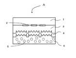
そして、透明基材1の一方の面をパターン状に活性化処理し(活性化処理領域2となる。)、または、透明基材1上のパターン状の活性化処理領域2以外の領域を、不活性化処理し(図示せず。)、さらには、透明基材1の全面を、一度、活性化処理した後(図示せず。)、その上から、所望の部分(「パターン」以外の領域。)を不活性化処理する(図示せず。)方法を用いることにより、活性化処理領域2における、透明基材1とホログラム形成層3との間の剥離強度と、それ以外の領域もしくは不活性化処理領域における透明基材1とホログラム形成層3との間の剥離強度との差を、大きくすることができ、より確実にホログラム形成層を破断させることができる。(図1参照。)
透明基材1の厚さは、通常5〜250μmであるが、「ラベル」としての取り扱い適正から25〜100μmとすることが望ましい。
また、透明基材の一方の面に、透明な樹脂をコーティングして、この透明な樹脂に上記処理を行い、上記した効果を持たせても良い。この透明な樹脂には、上記した樹脂群に加え、下記するホログラム形成層に用いられる樹脂を使用することができる。Hereinafter, embodiments of the present invention will be described in detail with reference to the drawings.
(Transparent substrate)
The transparent substrate 1 used in the hologram label A of the present invention can be reduced in thickness, and has mechanical strength and solvent resistance suitable for processing and processing when producing the hologram label A and What has heat resistance is preferable. Since it depends on the purpose of use, it is not limited, but a film-like or sheet-like plastic is preferable.
For example, various plastic films such as polyethylene terephthalate (PET), polycarbonate, polyvinyl alcohol, polysulfone, polyethylene, polypropylene, polystyrene, polyarylate, triacetyl cellulose (TAC), diacetyl cellulose, and polyethylene / vinyl alcohol can be exemplified. .
And one side of the transparent substrate 1 is activated in a pattern (becomes an activation process region 2), or a region other than the pattern
The thickness of the transparent substrate 1 is usually 5 to 250 μm, but is preferably 25 to 100 μm for proper handling as a “label”.
Further, a transparent resin may be coated on one surface of the transparent substrate, and the above-described effects may be obtained by performing the above-described treatment on the transparent resin. In addition to the above resin group, the resin used for the hologram forming layer described below can be used for this transparent resin.
さらに、活性化処理面と不活性化処理面との剥離強度の差を拡大する目的で、ホログラム形成層3上に保護層として形成され、透明基材1との剥離性を有する透明な樹脂を設けてもよい。この場合も、透明な樹脂としては、上記した樹脂群に加え、下記するホログラム形成層3に用いられる樹脂を、適宜、使用することができる。
もちろん、環境影響を配慮して、透明な生分解性を有するプラスチックフィルム又はシートを使用することもでき、化学合成系として、ラクトン系樹脂:εーカプロラクトン、4−メチルカプロラクトン、3,5,5−トリメチルカプロラクトン、3,3,5−トリメチルカプロラクトン、βープロピオラクトン、γーブチロラクトン、δーバレロラクトン、エナントラクトンの単独重合体またはこれら2種以上のモノマーの共重合体、これらの混合物、ポリカプロラクトン、もしくは、ポリブチレンサクシネート系樹脂:ポリブチレンサクシネート・アジペート、ポリブチレンサクシネートとポリカプロラクトンとの混合物、ポリブチレンサクシネートとポリブチレンサクシネート・アジペートとの混合物、ポリブチレンサクシネート・アジペートとポリ乳酸との混合物、もしくは、ポリ乳酸、ポリ乳酸とD−乳酸との混合物など、もしくは、低分子量脂肪族ジカルボン酸と低分子量脂肪族ジオールより合成したポリエステル樹脂、例えばコハク酸とブタンジオール、エチレングリコールとの組み合わせや、シュウ酸とネオペンチルグリコール、ブタンジオール、エチレングリコールとの組み合わせなど、変性ポリビニルアルコールと脂肪族ポリエステル樹脂と澱粉の混合物、低分子量脂肪族ポリエステルに脂肪族イソシアネートを添加して重合させたものが好適である。
また、天然物系として、ゼラチンなどの動物性天然物質、セルロースなどの植物性天然物質:澱粉脂肪酸エステル、澱粉キトナン・セルロース等、微生物生産系として、ポリヒドロキシブチレートや、ポリエステル系:炭素源として3−ヒドロキシプロピオン酸、4−ヒドロキシ酪酸、γ―ブチロラクトンをベースとするP(3HB−CO―4HB)、炭素源としてプロピオン酸、吉草酸をベースとしたP(3HB−CO―3HV)等、が好適である。Furthermore, for the purpose of expanding the difference in peel strength between the activation treatment surface and the deactivation treatment surface, a transparent resin formed as a protective layer on the
Of course, in consideration of environmental impact, a transparent biodegradable plastic film or sheet can also be used. As a chemical synthesis system, a lactone resin: ε-caprolactone, 4-methylcaprolactone, 3, 5, 5 -Trimethylcaprolactone, 3,3,5-trimethylcaprolactone, β-propiolactone, γ-butyrolactone, δ-valerolactone, a homopolymer of enanthlactone or a copolymer of these two or more monomers, a mixture thereof, polycaprolactone Or, polybutylene succinate resin: polybutylene succinate adipate, a mixture of polybutylene succinate and polycaprolactone, a mixture of polybutylene succinate and polybutylene succinate adipate, polybutylene succinate adipate A mixture of polylactic acid, or a polylactic acid, a mixture of polylactic acid and D-lactic acid, or a polyester resin synthesized from a low molecular weight aliphatic dicarboxylic acid and a low molecular weight aliphatic diol, such as succinic acid and butanediol, ethylene Polymerization by adding aliphatic isocyanate to a mixture of modified polyvinyl alcohol, aliphatic polyester resin and starch, low molecular weight aliphatic polyester, such as combinations with glycols, oxalic acid and neopentyl glycol, butanediol, ethylene glycol, etc. What was made to be suitable is suitable.
In addition, natural products such as animal natural materials such as gelatin, plant natural materials such as cellulose: starch fatty acid ester, starch chitonan and cellulose, etc., as microbial production systems, polyhydroxybutyrate and polyester systems: as carbon source P (3HB-CO-4HB) based on 3-hydroxypropionic acid, 4-hydroxybutyric acid, γ-butyrolactone, propionic acid as carbon source, P (3HB-CO-3HV) based on valeric acid, etc. Is preferred.
(活性化処理)
透明基材1の一方の面に対する活性化処理には、炭酸ガスレーザー照射、遠赤外線炭酸ガスレーザー照射、172nm真空紫外線(VUV、エキシマ光)照射、酸素増感エキシマ光照射、プラズマ処理、オープンプラズマ処理、コロナ処理、電子線照射処理等の透明基材最表面の化学結合エネルギーよりも大きいフォトンエネルギー(7.2eV)、放電エネルギー、電子線エネルギー等により、透明基材最表面の化学結合を切断し、または、172nmの真空紫外線等のように、大気中の酸素に吸収されてオゾンまたは直接励起酸素を発生し、この接触により官能基を生成する等の物理的処理や、
過マンガン酸塩、過酸化物等の酸化剤を塗布することによる透明基材表面の酸化処理、プライマーコーティング処理、ビニル、エポキシ、メタクリキシ、アミノ、メルカプト、アクリロキシ、イソシアネート、またはスチリル、アルコキシオリゴマータイプシランカップリング剤を用いた処理等の化学的処理、真空処理であるアルゴンビームエッチング処理、透明基材を部分的に溶解するエッチング液処理、さらには機械的に透明基材表面を削り取るサンドブラスト加工等の物理的な処理等を用いて、活性化処理領域2を形成する。
この透明基材1の表面化活性化処理によって、透明基材1との接着性の弱い、すなわち、剥離強度の小さい樹脂に対しても、大きな剥離強度を得ることができる。(Activation process)
The activation treatment for one surface of the transparent substrate 1 includes carbon dioxide laser irradiation, far infrared carbon dioxide laser irradiation, 172 nm vacuum ultraviolet (VUV, excimer light) irradiation, oxygen sensitized excimer light irradiation, plasma treatment, and open plasma. The chemical bond on the outermost surface of the transparent substrate is cut by photon energy (7.2 eV), discharge energy, electron beam energy, etc. larger than the chemical bond energy on the outermost surface of the transparent substrate such as treatment, corona treatment, and electron beam irradiation treatment. Or physical treatment such as generation of functional groups by contact with ozone or directly excited oxygen that is absorbed by oxygen in the atmosphere, such as vacuum ultraviolet light of 172 nm,
Oxidation treatment of transparent substrate surface by applying oxidizing agents such as permanganate and peroxide, primer coating treatment, vinyl, epoxy, methacryloxy, amino, mercapto, acryloxy, isocyanate, or styryl, alkoxy oligomer type silane Chemical treatment such as treatment using a coupling agent, argon beam etching treatment that is vacuum treatment, etching solution treatment that partially dissolves the transparent substrate, and sandblasting that mechanically scrapes the transparent substrate surface, etc. The
By the surface activation treatment of the transparent substrate 1, a high peel strength can be obtained even for a resin having low adhesion to the transparent substrate 1, that is, a resin having a low peel strength.
以上の活性化処理を用いて、透明基材1の界面張力もしくは表面エネルギーを増大させる。ホログラム形成層3に用いる樹脂や、その形成方法によってその剥離強度は決まるため、界面張力値を一義的には指定できないが、その目安としては、60〜80mN/mが好適である。(ポリエチレンテレフタレート樹脂では、36mN/mが、60mN/mに増大し、ホログラム形成層としてのメラミン樹脂との剥離強度が0.4kg/25mm幅から2.1kg/25mm幅へと大きくなる。)
そのため、透明基材1の一方の面を活性化して、その上に形成するホログラム形成層3との接着性を向上させ、0.5kg/25mm幅以上、3.0kg/25mm幅以下の強度(JIS Z0237で規定する180°剥離試験にて。)とし、その活性化処理面を視認可能な所望のパターン状(文字、図形、記号等、視認可能な表示であればいずれも使用できる。代表的には、ラベルを剥離した証拠を示すという意味で、「開封」等の文字表示をするため、「開封」文字部分を活性化する。)とする。これが、活性化処理領域2となる。(図1参照。)
活性化処理の中でも、レーザー照射等の光処理、またはプラズマ処理等の物理的処理は、透明基材1の処理面に凹凸が発生せず、鏡面を維持していること、活性化処理面上への不活性化処理による不活性化効果が大きいこと、及び、光学的透明性にも優れることから、特に望ましい。
さらに、上記した「パターン」内を均一に活性化処理することに替えて、その「パターン」内をよりサイズの小さい「微細なパターン」、例えば、網点形状、市松模様状、ランダムパターン状等の微細な領域のみを活性化することで(例えば、網点形状に活性化することにより、「パターン」内の網点以外の部分は、未処理面として残る。)、透明基材1を剥離した際の破断する「きっかけ」を増し、その破断性を向上することができる。
好適には、30μm〜300μmの大きさの一様な網点(網点率は、30%〜70%が好適。その網点内のみ活性化処理する。)や、その大きさの升目を有する市松模様(正方形や、長方形、その他形状。一つ飛ばしに活性化処理する。)、さらには、規則的な処理による不要な回折現象を発生させることを回避するため、網点や市松模様の升目の大きさを30μm〜300μmの間で、ランダムに変化させたものを用いる。もちろん、その変化を全く無秩序なものとせず、所定の法則に従った、不連続な変化としてもよい。Using the above activation treatment, the interfacial tension or surface energy of the transparent substrate 1 is increased. Since the peel strength is determined by the resin used for the
Therefore, one surface of the transparent substrate 1 is activated to improve the adhesiveness with the
Among the activation treatments, light treatment such as laser irradiation or physical treatment such as plasma treatment does not cause unevenness on the treatment surface of the transparent substrate 1 and maintains a mirror surface, on the activation treatment surface. This is particularly desirable because it has a large deactivation effect due to the deactivation treatment and excellent optical transparency.
Further, instead of uniformly activating the above “pattern”, the “pattern” has a smaller “fine pattern”, for example, a halftone dot shape, a checkered pattern, a random pattern, etc. The transparent substrate 1 is peeled off by activating only the fine regions (for example, the portions other than the halftone dots in the “pattern” remain as untreated surfaces by activating the halftone dot shape). It is possible to increase the “trigger” for breaking and improve its breakability.
Preferably, it has a uniform halftone dot with a size of 30 μm to 300 μm (halftone dot ratio is preferably 30% to 70%. Activation is performed only within the halftone dot) and has a mesh of that size. Checkered pattern (square, rectangular, other shapes; one activation process is skipped), and to avoid the occurrence of unnecessary diffraction due to regular processing, halftone dots and checkered patterns The size is changed randomly between 30 μm and 300 μm. Of course, the change may not be disordered at all, but may be a discontinuous change according to a predetermined law.
(不活性化処理)
透明基材1の一方の面の活性化処理領域2以外の部分を選択的に不活性化処理したり、透明基材1の一方の面を全面活性化処理後に、「パターン」以外の部分を不活性化処理(表面処理を意味する。以下、同様の意味に用いる。)するなどの処理をするためには、
透明基材1の最表面のみを部分的に溶解する、もしくは、活性化した官能基と反応して官能基の活性を解消する、溶剤類、例えば、ケトン類(アセトン、メチルエチルケトン、メチルイソブチルケトン、シクロヘキサノン、ジアセトンアルコール、イソホロン、ジイソブチルケトン、等。)、アルコール類(メタノール、エタノール、イソプロピルアルコール、n−プロピルアルコール、イソブチルアルコール、n−ブチルアルコール等、さらにはその水溶液。)、芳香族類(ベンゼン、トルエン、キシレン、ソルベッソNo.100、ソルベッソNo.150、カクタスP−180等。)、環状炭化水素類(シクロヘキサン等)、エステル類(酢酸エチル、酢酸ブチル、酢酸イソブチル、プロピレングリコールモノメチルエーテルアセテート、酢酸セルソルブ、エチルー3−エトキシプロピオネート等。)、エーテル類(テトラヒドロフラン、メチルセロソルブ、エチルセロソルブ、ブチルセロソルブ、t−ブチルセロソルブ等。)等を「パターン」以外の領域に対して、活版印刷方式やインクジェット方式を用いて、活性化処理面への接触を避けてパターン形成し、透明基材1の活性化された最表面の部分のみと反応して、その部分のみを不活性化させる。
このとき、溶剤が瞬時に揮発せず、所定時間、透明基材表面に留まる必要があるため、その沸点は、60度以上200度以下、好適には、100度以上160度に調整する。
この方法は、透明基材1の表面粗さ(鏡面性)に悪影響をほとんど与えず、その性質のみを変化させるという意味で、特に好適である。(Inactivation process)
A portion other than the
Solvents such as ketones (acetone, methyl ethyl ketone, methyl isobutyl ketone, which dissolves only the outermost surface of the transparent substrate 1 or reacts with activated functional groups to eliminate the activity of the functional groups. Cyclohexanone, diacetone alcohol, isophorone, diisobutyl ketone, etc.), alcohols (methanol, ethanol, isopropyl alcohol, n-propyl alcohol, isobutyl alcohol, n-butyl alcohol, etc., and further aqueous solutions thereof), aromatics ( Benzene, toluene, xylene, Solvesso No. 100, Solvesso No. 150, Cactus P-180, etc.), cyclic hydrocarbons (cyclohexane, etc.), esters (ethyl acetate, butyl acetate, isobutyl acetate, propylene glycol monomethyl ether acetate) The , Cellulose acetate, ethyl-3-ethoxypropionate, etc.), ethers (tetrahydrofuran, methyl cellosolve, ethyl cellosolve, butyl cellosolve, t-butyl cellosolve, etc.), etc. A pattern is formed by using an ink jet method while avoiding contact with the activated surface, reacting only with the activated outermost surface portion of the transparent substrate 1, and inactivating only that portion.
At this time, since the solvent does not volatilize instantaneously and needs to remain on the surface of the transparent substrate for a predetermined time, the boiling point is adjusted to 60 degrees or more and 200 degrees or less, preferably 100 degrees or more and 160 degrees.
This method is particularly suitable in the sense that it hardly affects the surface roughness (specularity) of the transparent substrate 1 and only changes its properties.
または、透明基材1とはそもそも接着し難い、界面張力の小さい樹脂、例えば、シリコーン樹脂、パラフィン系樹脂、フッ素系樹脂や、これらのフッ化炭化水素基、有機珪素基を含む樹脂や、不揮発油(リンシードオイル、ポピーオイル、ウォルナッツオイル等の乾性油、オリーブオイルや落花生油等の不乾性油、ゴマ油、ナタネ油等の半乾性油)等を、活版印刷や、インクジェット印刷等により、上記した「パターン」以外の領域(図示せず。)に部分形成することで、高い精度で不活性化処理することができる。
この際、部分形成後に透明基材1上に光学的な変化を与えないことが望ましく、溶剤等は揮発することで、また、樹脂等はあくまで表面改質の目的であって乾燥後の形成厚さが光の波長の1/5〜1/50程度となることが望ましい。もちろん、これらを併用することも好適である。
もちろんその「パターン」を「微細なパターン」の集合で構成した場合も同様である。
この不活性化処理により、その不活性化処理面は、透明基材1とホログラム形成層3との剥離強度を、0.01kg/25mm幅以上0.1kg/25mm幅以下とすることができ、ホログラムラベルAを剥そうとすると、どのように工夫しても、必ず、透明基材1とホログラム形成層3間に「すきま」が発生し、透明基材のみが剥離し始めることとなる。
そして、透明基材1を剥離した部分、すなわち、不活性化処理面にあたるホログラム形成層3の最表面がほぼ鏡面となって、その部分からは、その下にあるホログラム再生像を鮮明に視認することができる。Alternatively, it is difficult to adhere to the transparent substrate 1 in the first place, and a resin having a low interfacial tension, such as a silicone resin, a paraffin resin, a fluorine resin, a resin containing these fluorinated hydrocarbon groups or organic silicon groups, or a non-volatile Oil (dry seed oil such as linseed oil, poppy oil, walnut oil, non-drying oil such as olive oil and peanut oil, semi-drying oil such as sesame oil and rapeseed oil), etc. by typographic printing, inkjet printing, etc. By performing partial formation in a region other than the “pattern” (not shown), inactivation processing can be performed with high accuracy.
At this time, it is desirable not to give an optical change on the transparent substrate 1 after the partial formation, the solvent etc. is volatilized, and the resin etc. is only for the purpose of surface modification and the formation thickness after drying Is preferably about 1/5 to 1/50 of the wavelength of light. Of course, it is also suitable to use these in combination.
Of course, the same applies to the case where the “pattern” is composed of a set of “fine patterns”.
By this deactivation treatment, the deactivation treatment surface can set the peel strength between the transparent substrate 1 and the
And the part which peeled the transparent base material 1, ie, the outermost surface of the
(ホログラム形成層)
本発明のホログラム形成層3を構成するための透明な樹脂材料としては、各種の熱可塑性樹脂、熱硬化性樹脂、もしくは電離放射線硬化性樹脂を用いることができる。熱可塑性樹脂としてはアクリル酸エステル樹脂、アクリルアミド樹脂、ニトロセルロース樹脂、もしくはポリスチレン樹脂等が、また、熱硬化性樹脂としては、不飽和ポリエステル樹脂、アクリルウレタン樹脂、エポキシ変性アクリル樹脂、エポキシ変性不飽和ポリエステル樹脂、アルキッド樹脂、もしくはフェノール樹脂等が挙げられる。(図1参照。)
これらの熱可塑性樹脂および熱硬化性樹脂は、1種もしくは2種以上を使用することができる。これらの樹脂の1種もしくは2種以上は、各種イソシアネート樹脂を用いて架橋させてもよいし、あるいは、各種の硬化触媒、例えば、ナフテン酸コバルト、もしくはナフテン酸亜鉛等の金属石鹸を配合するか、または、熱もしくは紫外線で重合を開始させるためのベンゾイルパーオキサイド、メチルエチルケトンパーオキサイド等の過酸化物、ベンゾフェノン、アセトフェノン、アントラキノン、ナフトキノン、アゾビスイソブチロニトリル、もしくは、ジフェニルスルフィド等を配合しても良い。
また、電離放射線硬化性樹脂としては、エポキシアクリレート、ウレタンアクリレート、アクリル変性ポリエステル等を挙げることができ、このような電離放射線硬化性樹脂に架橋構造を導入するか、もしくは粘度を調整する目的で、単官能モノマーもしくは多官能モノマー、またはオリゴマー等を配合して用いてもよい。
そして、ホログラム形成層3を構成する透明な樹脂材料に、無色で透明性が高く、マイクロカプセルに含ませた蛍光剤を励起する波長の紫外線を吸収する性能を有し、さらには、ホログラムレリーフ形成時の加熱・加圧において変性(性能が劣化することを意味する。)することのない、紫外線吸収剤を、その樹脂に対して5%〜10%質量部混入させたものを用いることができる。(Hologram forming layer)
As the transparent resin material for constituting the
These thermoplastic resins and thermosetting resins can be used alone or in combination of two or more. One or more of these resins may be cross-linked using various isocyanate resins, or various curing catalysts, for example, metal soap such as cobalt naphthenate or zinc naphthenate may be blended. Or peroxide such as benzoyl peroxide or methyl ethyl ketone peroxide for initiating polymerization with heat or ultraviolet light, benzophenone, acetophenone, anthraquinone, naphthoquinone, azobisisobutyronitrile, or diphenyl sulfide. Also good.
Examples of the ionizing radiation curable resin include epoxy acrylate, urethane acrylate, acrylic-modified polyester, etc., for the purpose of introducing a crosslinked structure into such an ionizing radiation curable resin or adjusting the viscosity, A monofunctional monomer, a polyfunctional monomer, or an oligomer may be blended and used.
The transparent resin material constituting the
上記の樹脂材料を用いてホログラム形成層3を形成するには、感光性樹脂材料にホログラムの干渉露光を行なって現像することによって直接的に形成することもできるが、予め作成したレリーフホログラムもしくはその複製物、またはそれらのメッキ型等を複製用型として用い、その型面を上記の樹脂材料の層に押し付けることにより、賦型を行なうのがよい。
熱硬化性樹脂や電離放射線硬化性樹脂を用いる場合には、型面に未硬化の樹脂を密着させたまま、加熱もしくは電離放射線照射により、硬化を行わせ、硬化後に剥離することによって、硬化した透明な樹脂材料からなる層の片面にレリーフホログラムの微細凹凸を形成することができる。なお、同様な方法によりパターン状に形成して模様状とした回折格子を有する回折格子形成層も光回折構造として使用できる。
レリーフホログラムは、物体光と参照光との光の干渉による干渉縞を凹凸のレリーフ形状で記録されたもので、例えば、フレネルホログラムなどのレーザ再生ホログラム、及びレインボーホログラムなどの白色光再生ホログラム、さらに、それらの原理を利用したカラーホログラム、コンピュータジェネレーティッドホログラム(CGH)、ホログラフィック回折格子などがある。また、マシンリーダブルホログラムのように、その再生光を受光部でデータに変換し所定の情報として伝達したり、真偽判定を行うものであってもよい。In order to form the
When thermosetting resin or ionizing radiation curable resin is used, curing is performed by heating or ionizing radiation irradiation while keeping the uncured resin in close contact with the mold surface, and then cured by peeling after curing. The fine irregularities of the relief hologram can be formed on one side of the layer made of a transparent resin material. A diffraction grating forming layer having a diffraction grating formed in a pattern by a similar method can also be used as the optical diffraction structure.
A relief hologram is a recording of interference fringes due to interference of light between object light and reference light in an uneven relief shape. For example, a laser reproduction hologram such as a Fresnel hologram, a white light reproduction hologram such as a rainbow hologram, There are color holograms utilizing these principles, computer generated holograms (CGH), holographic diffraction gratings, and the like. Further, like a machine readable hologram, the reproduction light may be converted into data by a light receiving unit and transmitted as predetermined information, or authenticity may be determined.
微細な凹凸を精密に作成するため、光学的な方法だけでなく、電子線描画装置を用いて、精密に設計されたレリーフ構造を作り出し、より精密で複雑な再生光を作り出すものであってもよい。このレリーフ形状は、ホログラムを再現もしくは再生する光もしくは光源の波長(域)と、再現もしくは再生する方向、及び強度によってその凹凸のピッチや、深さ、もしくは特定の周期的形状が設計される。凹凸のピッチ(周期)は再現もしくは再生角度に依存するが、通常0.1μm〜数μmであり、凹凸の深さは、再現もしくは再生強度に大きな影響を与える要素であるが、通常0.1μm〜1μmである。
単一回折格子のように、全く同一形状の凹凸の繰り返しであるものは、隣り合う凹凸が同じ形状であればある程、反射する光の干渉度合いが増しその強度が強くなり、最大値へと収束する。回折方向のぶれも最小となる。立体像のように、画像の個々の点が焦点に収束するものは、その焦点への収束精度が向上し、再現もしくは再生画像が鮮明となる。
さらに、反射性薄膜層4が透明金属化合物等からなる透明反射性薄膜の場合には、その薄膜層の上下の面が、同一レリーフ形状であり、且つ、その面と面の距離(すなわち膜厚さ)が均一であればあるほど、再現もしくは再生強度が大きくなる。また、レリーフ面にホログラム画像の凹凸とは異なる周期、形状の凹凸が存在すると、それはホログラムもしくは回折格子の再現もしくは再生時のノイズとなり、画像を不鮮明にする要因となる。
レリーフ形状を賦形(複製ともいう)する方法は、回折格子や干渉縞が凹凸の形で記録された原版をプレス型(スタンパという)として用い、上記ホログラム形成層3上に、もしくは、下記する透明反射性薄膜層4上に、前記原版を重ねて加熱ロールなどの適宜手段により、両者を加熱圧着することにより、原版の凹凸模様を複製することができる。形成するホログラムパターンは単独でも、複数でもよい。
上記の極微細な形状を精密に再現するため、また、複製後の熱収縮などの歪みや変形を最小とするため、原版は金属を使用し、低温・高圧下で複製を行う。In order to precisely create fine irregularities, not only optical methods, but also electron beam lithography equipment can be used to create precisely designed relief structures that produce more precise and complex reproduction light. Good. The relief shape is designed to have a pitch, depth, or specific periodic shape of the unevenness according to the wavelength (range) of the light or light source for reproducing or reproducing the hologram, the direction and the intensity of reproduction or reproduction. The pitch (period) of the unevenness depends on the reproduction or reproduction angle, but is usually 0.1 μm to several μm, and the depth of the unevenness is a factor that greatly affects the reproduction or reproduction intensity, but is usually 0.1 μm. ˜1 μm.
As in the case of a single diffraction grating, when the unevenness of exactly the same shape is repeated, as the adjacent unevenness is the same shape, the degree of interference of reflected light increases and the intensity increases, and the maximum value is reached. Converge. Diffraction in the diffraction direction is also minimized. When a single point of an image converges to a focal point, such as a stereoscopic image, the convergence accuracy to the focal point is improved, and a reproduced or reproduced image becomes clear.
Further, when the reflective
The relief shape is shaped (also referred to as replication) by using an original plate on which diffraction gratings and interference fringes are recorded in a concavo-convex shape as a press die (referred to as a stamper) on the
In order to accurately reproduce the above-mentioned extremely fine shape and to minimize distortion and deformation such as heat shrinkage after replication, the original plate is made of metal and replicated at low temperature and high pressure.
原版は、Niなどの硬度の高い金属を用いる。光学的撮影もしくは、電子線描画などにより形成したガラスマスターなどの表面にCr、Ni薄膜を真空蒸着法、スパッタリングなどにより5〜50nm形成後、Niなどを電着法(電気めっき、無電解めっき、さらには複合めっきなど)により50〜1000μm形成した後、金属を剥離することで作ることができる。
高圧回転式の複製に用いるためには、このNi層の厚み精度を高くする必要があり、通常±10μm、好ましくは、±1μmとする。このため、裏面の研磨や、平坦化方法を用いてもよい。
複製方式は、高圧とするため、平板式でなく、回転式を用い、線圧0.1トン/m〜10トン/m、好ましくは、5トン/m以上とする。複製用シリンダーは、その直径が小さいとレリーフの再現性が低下するため、複製シリンダー直径は大きい方が好ましく、通常、直径0.1m〜2.0m、好ましくは、1.0m以上の弧を使用する。
透明基材1上のホログラム形成層3をこの複製用シリンダーに沿って押し当て、裏面より金属製シリンダーにより上記圧力にて複製を実施する。複製後の熱収縮などの歪みや変形を最小限とするためには、透明な基材1全体を加熱するのではなく、ホログラム形成層3面側の一部のみを加熱する方法が望ましい。通常60℃〜110℃に加熱する。さらには、裏面の金属製シリンダーを常温に保つ、もしくは冷却することで、さらにその精度を向上させることができる。The original plate uses a metal having high hardness such as Ni. After a Cr or Ni thin film is formed on the surface of a glass master or the like formed by optical photography or electron beam drawing by vacuum deposition or sputtering, Ni or the like is electrodeposited (electroplating, electroless plating, Furthermore, after forming 50-1000 micrometers by composite plating etc., it can make by peeling a metal.
In order to use it for high-pressure rotation type replication, it is necessary to increase the thickness accuracy of this Ni layer, and it is usually ± 10 μm, preferably ± 1 μm. For this reason, you may use the back surface grinding | polishing or the planarization method.
Since the replication method is a high pressure, a rotary method is used instead of a flat plate method, and the linear pressure is 0.1 ton / m to 10 ton / m, preferably 5 ton / m or more. If the diameter of the duplication cylinder is small, the reproducibility of the relief is lowered. Therefore, it is preferable that the duplication cylinder diameter is large. Usually, an arc having a diameter of 0.1 m to 2.0 m, preferably 1.0 m or more is used. To do.
The
(反射性薄膜層)
本発明のホログラムラベルAでは、ホログラム形成層3の上に形成されているホログラムレリーフに接して、且つ、追従するように反射性薄膜層4を形成する。この反射性薄膜層4は、入射した光を反射する必要があるため、透明基材1よりも高い屈折率を有する薄膜であれば、特に限定されない。(図1参照。)
反射性薄膜層4としては、真空薄膜法などにより形成される金属薄膜などの金属光沢反射層、又は透明反射層のいずれでもよいが、金属光沢反射層を部分的に設けたり、透明反射層を設けた場合は、ラベル貼着後にそのラベルに覆われた被貼着体上の画像などがホログラムを通して観察できるので好ましい。
透明反射層としては、ほぼ無色透明な色相で、その光学的な屈折率がホログラム形成層3のそれとは異なることにより、金属光沢が無いにもかかわらず、ホログラムなどの光輝性を視認できることから、透明なホログラムを作製することができる。
例えば、ホログラム形成層3よりも光屈折率の高い薄膜には、例として、ZnS、TiO2、Al2O3、Sb2S3、SiO、SnO2、ITOなどがある。
好ましくは、金属酸化物又は窒化物であり、具体的には、Be、Mg、Ca、Cr、Mn、Cu、Ag、Al、Sn、In、Te、Ti、Fe、Co、Zn、Ge、Pb、Cd、Bi、Se、Ga、Rb、Sb、Pb、Ni、Sr、Ba、La、Ce、Auなどの酸化物又は窒化物他はそれらを2種以上を混合したものなど(透明金属化合物)が例示できる。
またアルミニウムなどの一般的な光反射性(可視光波長のほぼ全域にわたる反射、すなわち、「全反射」に近い性質を有する。)の金属薄膜も、厚みが20nm以下になると、透明性が出て使用できる。
透明反射層(透明金属化合物層)の形成は、金属の薄膜と同様、10〜2000nm程度、好ましくは20〜1000nmの厚さになるよう、蒸着、スパッタリング、イオンプレーティング、CVD(化学蒸着法)などの真空薄膜法などにより設ければよい。特にCVD法はホログラム形成層3への熱的ダメージが少ない。また、他の薄膜形成法を用いても、形成する薄膜層を薄くしておくと、その熱的ダメージを少なくすることができる。例えば、アルミニウム蒸着層であれば、形成条件によるが、厚さにして、ほぼ20nmのものあたりが、透明性が無くなり全反射性を出現する臨界点である。この厚さは薄膜材料、形成方法、金属加熱温度・真空度等の形成条件により異なる。(Reflective thin film layer)
In the hologram label A of the present invention, the reflective
The reflective
As the transparent reflective layer, it is a substantially colorless and transparent hue, and its optical refractive index is different from that of the
For example, examples of the thin film having a higher refractive index than the
Preferably, it is a metal oxide or nitride, specifically, Be, Mg, Ca, Cr, Mn, Cu, Ag, Al, Sn, In, Te, Ti, Fe, Co, Zn, Ge, Pb. , Cd, Bi, Se, Ga, Rb, Sb, Pb, Ni, Sr, Ba, La, Ce, Au, etc. Oxides or nitrides, etc., or a mixture of two or more thereof (transparent metal compound) Can be illustrated.
In addition, a metal thin film having a general light reflectivity (reflection over almost the entire visible light wavelength, that is, a property close to “total reflection”) such as aluminum has transparency when the thickness is 20 nm or less. Can be used.
The transparent reflective layer (transparent metal compound layer) is formed by vapor deposition, sputtering, ion plating, CVD (chemical vapor deposition) so as to have a thickness of about 10 to 2000 nm, preferably 20 to 1000 nm, like a metal thin film. It may be provided by a vacuum thin film method or the like. In particular, the CVD method causes little thermal damage to the
(粘着層)
粘着層6に用いる粘着剤としては、従来公知の溶剤系及び水系のいずれの粘着剤、例えば、酢酸ビニル樹脂、アクリル樹脂、酢酸ビニル−アクリル共重合体、酢酸ビニル−塩化ビニル共重合体、エチレン−酢酸ビニル共重合体、ポリウレタン樹脂や、天然ゴム、クロロプレンゴムなどのゴム系樹脂などが挙げられる。自然にやさしい材料構成とするために、特に、天然ゴムを主成分とするラテックス、それを変性したもの、特に天然ゴムにスチレン特にメタクリルさんメチルとをグラフト重合させて得た天然ゴムラテックス等の天然素材から作製されたものを用いても良い。
この粘着剤に、適宜な溶剤と、平均直径5μm〜60μmのマイクロカプセル5を加え、そのマイクロカプセル5を破壊することがないように、低速撹拌等の負荷のかからない分散手段を用いて処理し、粘着剤中にマイクロカプセル5を均一に分散させる。
粘着層6に用いられる溶剤としては、
溶剤類、例えば、ケトン類(アセトン、メチルエチルケトン、メチルイソブチルケトン、シクロヘキサノン、ジアセトンアルコール、イソホロン、ジイソブチルケトン、等。)、アルコール類(メタノール、エタノール、イソプロピルアルコール、n−プロピルアルコール、イソブチルアルコール、n−ブチルアルコール等、さらにはその水溶液。)、芳香族類(ベンゼン、トルエン、キシレン、ソルベッソNo.100、ソルベッソNo.150、カクタスP−180等。)、環状炭化水素類(シクロヘキサン等)、エステル類(酢酸エチル、酢酸ブチル、酢酸イソブチル、プロピレングリコールモノメチルエーテルアセテート、酢酸セルソルブ、エチルー3−エトキシプロピオネート等。)、エーテル類(テトラヒドロフラン、メチルセロソルブ、エチルセロソルブ、ブチルセロソルブ、t−ブチルセロソルブ等。)等を用いることができる。(Adhesive layer)
The pressure-sensitive adhesive used for the pressure-
To this pressure-sensitive adhesive, an appropriate solvent and
As a solvent used for the
Solvents such as ketones (acetone, methyl ethyl ketone, methyl isobutyl ketone, cyclohexanone, diacetone alcohol, isophorone, diisobutyl ketone, etc.), alcohols (methanol, ethanol, isopropyl alcohol, n-propyl alcohol, isobutyl alcohol, n -Butyl alcohol, etc., and its aqueous solution.), Aromatics (benzene, toluene, xylene, Solvesso No. 100, Solvesso No. 150, Cactus P-180, etc.), cyclic hydrocarbons (cyclohexane, etc.), esters (Ethyl acetate, butyl acetate, isobutyl acetate, propylene glycol monomethyl ether acetate, cellosolve acetate, ethyl-3-ethoxypropionate, etc.), ethers (tetrahydrofuran, methyl Cellosolve, ethyl cellosolve, butyl cellosolve, t-butyl cellosolve.) And the like can be used.
粘着剤中のマイクロカプセル5の含有量は、10%〜70%質量部とし、そのマイクロカプセル5内の、マイクロカプセル5全体に対する「蛍光剤及び液状物質」の含有量は、10%以上40%以内とする。そして、その蛍光剤と液状物質の混合割合は、1/2〜1/10とする。
この蛍光剤を含むマイクロカプセル5を含有している粘着層6を形成する方法としては、上記した大きさを有するマイクロカプセル5を含む粘着剤6を、マイクロカプセル5を破壊することなく、反射性薄膜層4上に、均一な厚さに設けるため、凹版印刷法、スクリーン印刷方法、カーテンコート法その他、フォトレジスト法等を用いる。(図1参照。)
マイクロカプセルに含まれる蛍光剤としては、
紫外線、赤外線、電子線、X線などの可視光線以外のエネルギーを吸収して励起し、可視光線を放出する物質を用いることができる。
具体的には、以下の蛍光体原料等を使用することができる。
Baを含む蛍光体原料としては、BaO、Ba(OH)2・8H2O、BaCO3、Ba(NO3)2、BaSO4、Ba(C2O4)・2H2O、Ba(OCOCH3)2、BaCl2等、Caを含む蛍光体原料としては、CaO、Ca(OH)2、CaCO3、Ca(NO3)2・4H2O、CaSO4・2H2O、Ca(C2O4)・H2O、Ca(OCOCH3)2・H2O、無水CaCl2(但し、水和物であってもよい。)等、Srを含む蛍光体原料としては、SrO、Sr(OH)2・8H2O、SrCO33、Sr(NO33)2、SrSO4、Sr(C2O4)・H2O、Sr(OCOCH3)2・0.5H2O、SrCl2等、Znを含む蛍光体原料としては、ZnO、Zn(C2O4)・2H2O、ZnSO4・7H2O等、Mgを含む蛍光体原料としては、MgCO3、MgO、MgSO4、Mg(C2O4)・2H2O等、Siを含む蛍光体原料としては、SiO2、H4SiO4、Si(OCOCH3)4等、Euを含む蛍光体原料体例としては、Eu2O3、Eu2(SO4)3、Eu2(C2O4)3、EuCl2、EuCl3、Eu(NO3)3・6H2O等、Sm、Tm及びYbを含む各蛍光体原料としては、Eu源の具体例として挙げた各化合物において、EuをそれぞれSm、Tm及びYbに置き換えた化合物が挙げられる。The content of the
As a method of forming the pressure-
As the fluorescent agent contained in the microcapsule,
A substance that absorbs and excites energy other than visible light such as ultraviolet rays, infrared rays, electron beams, and X-rays and emits visible rays can be used.
Specifically, the following phosphor raw materials can be used.
Examples of the phosphor material containing Ba include BaO, Ba (OH)2 .8H2 O, BaCO3 , Ba (NO3 )2 , BaSO4 , Ba (C2 O4 ) · 2H2 O, Ba (OCOCH3 )2 , BaCl2 , and other phosphor materials containing Ca include CaO, Ca (OH)2 , CaCO3 , Ca (NO3 )2 .4H2 O, CaSO4 .2H2 O, Ca (C2 O4 ) .H2 O, Ca (OCOCH 3)2 .H2 O, anhydrous CaCl2 (however, it may be a hydrate), etc., as phosphor raw materials containing Sr, SrO, Sr (OH)2 · 8H2 O, SrCO33 , Sr (NO3 3)2 , SrSO4 , Sr (C2 O4 ) · H2 O, Sr (OCOCH3 )2 · 0.5H2 O, SrCl2 , Zn, etc. the phosphor raw materialcontaining, ZnO, Zn (C 2 O 4) · 2H 2 O,
また、Mnを含む蛍光体原料としては、MnO、MnO2、Mn2O3、MnF2、MnCl2、MnBr2、Mn(NO3)2・6H2O、MnCO3、MnCr2O4等、Crを含む蛍光体原料としては、Cr2O3、CrF3(水和物含む。)、CrCl3、CrBr3・6H2O、Cr(NO3)2・9H2O、(NH4)2CrO4等、Tbを含む蛍光体原料としては、Tb4O7、TbCl3(水和物を含む。)、TbF3、Tb(NO3)3・nH2O、Tb2(SiO4)3、Tb2(C2O4)3・10H2O等、また、他の蛍光体原料(例えば、Eu源)とTb源とを共沈させてから用いることもでき、Prを含む蛍光体原料としては、Pr2O3、PrCl3、PrF3、Pr(NO3)3・6H2O、Pr2(SiO4)3、Pr2(C2O4)3・10H2O等、Ceを含む蛍光体原料としては、CeO2、CeCl3、Ce2(CO3)3・5H2O、CeF3、Ce(NO3)3・6H2O等、Luを含む蛍光体原料としては、Lu2O3、LuCl3、LuF3(水和物を含む。)、Lu(NO3)3(水和物を含む。)等、Laを含む蛍光体原料としては、La2O3、LaCl3・7H2O、La2(CO3)3・H2O、LaF3、La(NO3)3・6H2O、La2(SO4)3等、Gdを含む蛍光体原料としては、Gd2O3、GdCl3・6H2O、Gd(NO3)3・5H2O、Gd2(SO4)3・8H2O、GdF3等が挙げられる。
さらに、Geを含む蛍光体原料としては、GeO2、Ge(OH)4、Ge(OCOCH3)4、GeCl4等、Gaを含む蛍光体原料としては、Ga2O3、Ga(OH)3、Ga(NO3)3・nH2O、Ga2(SO4)3、GaCl3等、Alを含む蛍光体原料としてはα−Al2O3、γ−Al2O3等のAl2O3、Al(OH)3、AlOOH、Al(NO3)3・9H2O、Al2(SO4)3、AlCl3等、Pを含む蛍光体原料としては、P2O5、Ba3(PO4)2、Sr3(PO4)2、(NH4)3PO4等、Bを含む蛍光体原料としては、B2O3、H3BO3等が挙げられる。
なお、上記に例示した原料は、必要に応じて共沈させてから用いてもよい。
さらに、N元素、O元素及びハロゲン元素等に対応する蛍光体原料は、通常、上記各蛍光体構成元素の蛍光体原料のアニオン成分として、又は焼成雰囲気中に含有される成分として、蛍光体製造時に供給される。Examples of phosphor materials containing Mn include MnO, MnO2 , Mn2 O3 , MnF2 , MnCl2 , MnBr2 , Mn (NO3 )2 .6H2 O, MnCO3 , MnCr2 O4, etc. As phosphor raw materials containing Cr, Cr2 O3 , CrF3 (including hydrates), CrCl3 , CrBr3 .6H2 O, Cr (NO3 )2 .9H2 O, (NH4 )2 Examples of phosphor raw materials containing Tb such as CrO4 include Tb4 O7 , TbCl3 (including hydrates), TbF3 , Tb (NO3 )3 .nH2 O, Tb2 (SiO4 )3. , Tb2 (C2 O4 )3 · 10H2 O, etc., and other phosphor materials (for example, Eu source) and Tb source can be used after coprecipitation, and phosphor materials containing Pr As, Pr2 O3 , PrCl3 , PrF3 , Pr (NO3 )3 .6H2 O, Pr2 (SiO4 )3 , Pr2 (C2 O4 )3 .10H2 O and the like phosphor materials containing Ce include CeO2 , CeCl3 , Ce2 (CO3 )3 .5H2 O, CeF3 , Ce (NO3) 3 · 6H2 O, etc., as a phosphor raw material containing Lu, Lu including2 O 3, LuCl 3, LuF 3 ( hydrate.), including Lu (NO3) 3 (hydrate. ) Etc., phosphor materials containing La include La2 O3 , LaCl3 .7H2 O, La2 (CO3 )3 .H2 O, LaF3 , La (NO3 )3 · 6H2 O, As phosphor materials containing Gd, such as La2 (SO4 )3 , Gd2 O3 , GdCl3 .6H2 O, Gd (NO3 )3 / 5H2 O, Gd2 (SO4 )3 · 8H2 O, GdF3 and the like.
Further, as phosphor materials containing Ge, GeO2 , Ge (OH)4 , Ge (OCOCH3 )4 , GeCl4, etc. As phosphor materials containing Ga, Ga2 O3 , Ga (OH)3, Ga (NO 3) 3 · nH 2 O, Ga 2 (SO 4) 3,
In addition, you may use the raw material illustrated above, after coprecipitating as needed.
Further, phosphor raw materials corresponding to N element, O element, halogen element, etc. are usually manufactured as phosphors as anion components of the phosphor raw materials of the respective phosphor constituting elements or as components contained in the firing atmosphere. Sometimes supplied.
蛍光体原料を混合して原料混合物を調製してから、原料混合物を所定温度、雰囲気下で焼成する。この際、混合は十分に行うことが好ましい。
上記混合手法としては、特に限定はされないが、具体的には、下記(A)及び(B)として挙げた手法を用いることができる。また、これらの各種条件については、例えば、ボールミルにおいて2種の粒径の異なるボールを混合して用いる等の条件を選択可能である
。
(A)例えばハンマーミル、ロールミル、ボールミル、ジェットミル等の乾式粉砕機、又は、乳鉢と乳棒等を用いる粉砕と、例えばリボンブレンダー、V型ブレンダー、ヘンシェルミキサー等の混合機、又は、乳鉢と乳棒を用いる混合とを組み合わせ、前述の蛍光体原料を粉砕混合する乾式混合法。
(B)前述の蛍光体原料に例えばメタノール、エタノール等のアルコール系溶媒又は水などの溶媒又は分散媒を加え、例えば粉砕機、乳鉢と乳棒、又は蒸発皿と撹拌棒等を用いて混合し、溶液又はスラリーの状態とした上で、噴霧乾燥、加熱乾燥、又は自然乾燥等により乾燥させる湿式混合法。
蛍光体原料の混合は、蛍光体原料の物性に応じて、湿式又は乾式のいずれかを選択することができる。
また、ハロゲン化物、窒化物等の酸化・吸湿し易い原料を用いる場合には、例えばアルゴンガス、窒素ガス等の不活性気体を充填し、水分管理されたグローブボックス内でミキサー混合する。(図示せず。)After preparing a raw material mixture by mixing phosphor raw materials, the raw material mixture is fired at a predetermined temperature and atmosphere. At this time, it is preferable to perform the mixing sufficiently.
Although it does not specifically limit as said mixing method, Specifically, the method quoted as the following (A) and (B) can be used. As for these various conditions, for example, it is possible to select conditions such as mixing and using two kinds of balls having different particle diameters in a ball mill.
(A) Dry pulverizer such as hammer mill, roll mill, ball mill, jet mill, etc., or pulverization using mortar and pestle, and mixer such as ribbon blender, V-type blender, Henschel mixer, or mortar and pestle And a dry mixing method in which the above phosphor raw materials are pulverized and mixed.
(B) Add a solvent or dispersion medium such as an alcohol solvent such as methanol or ethanol or water to the phosphor raw material, and mix using, for example, a pulverizer, a mortar and pestle, or an evaporating dish and a stirring bar, A wet mixing method in which a solution or slurry is made and then dried by spray drying, heat drying, or natural drying.
The mixing of the phosphor raw material can be either wet or dry depending on the physical properties of the phosphor raw material.
In addition, when using a material that easily oxidizes and absorbs moisture, such as halide and nitride, for example, an inert gas such as argon gas or nitrogen gas is filled and mixed in a glove box in which moisture is controlled. (Not shown)
また、混合・粉砕時に、粒径を揃える等の目的で、蛍光体原料を篩いにかけても良い。この場合、各種市販の篩いを用いることが可能であるが、金属メッシュのものよりもナイロンメッシュ等の樹脂製のものを用いる方が、不純物混入防止の点で好ましい。
焼成工程では、得られた原料混合物を焼成することにより焼成物を得る。得られた焼成物は、通常、その組成は目的とする蛍光体のものとなっているが、その粒子は焼結して焼成ケーキとなっている。
さらに、焼成において、焼成炉中の耐熱容器の数が多い場合には、例えば、上記の昇温速度を遅めにする等、各耐熱容器への熱の伝わり具合を均等にすることが、ムラなく焼成するためには好ましい。
焼成工程における焼成温度、圧力、雰囲気等の焼成条件は、製造しようとする蛍光体そ
れぞれに応じて適切な条件を設定することが好ましい。
さらに、耐湿性等の耐候性を一層向上させるために、または、蛍光剤の樹脂に対する分散性を向上させるために、必要に応じて、蛍光剤の表面を異なる物質で被覆する等の表面処理を行なってもよい。(図示せず。)In addition, the phosphor material may be sieved for the purpose of, for example, uniforming the particle size during mixing and pulverization. In this case, various types of commercially available sieves can be used, but it is preferable to use a resin mesh such as a nylon mesh rather than a metal mesh in terms of preventing impurities from being mixed.
In the firing step, a fired product is obtained by firing the obtained raw material mixture. The obtained fired product usually has the composition of the intended phosphor, but the particles are sintered into a fired cake.
Furthermore, when the number of heat-resistant containers in the baking furnace is large in baking, for example, the rate of heat transfer to each heat-resistant container can be made uniform, for example, by slowing the temperature increase rate. It is preferable for firing without any problems.
The firing conditions such as the firing temperature, pressure, and atmosphere in the firing step are preferably set appropriately for each phosphor to be manufactured.
Furthermore, in order to further improve the weather resistance such as moisture resistance or to improve the dispersibility of the fluorescent agent in the resin, a surface treatment such as coating the surface of the fluorescent agent with a different substance is performed as necessary. You may do it. (Not shown)
蛍光剤の表面に存在させることのできる物質(以下「表面処理物質」とも称する。)の例としては、例えば、有機化合物、無機化合物、ガラス材料等を挙げることができる。 有機化合物の例としては、アクリル樹脂、ポリカーボネート、ポリアミド、ポリエチレン等の熱溶融性ポリマー、ラテックス、ポリオルガノシロキサン等が挙げられる。
無機化合物の例としては、酸化マグネシウム、酸化アルミニウム、酸化珪素、酸化チタン、酸化ジルコニウム、酸化スズ、酸化ゲルマニウム、酸化タンタル、酸化ニオブ、酸化バナジウム、酸化硼素、酸化アンチモン、酸化亜鉛、酸化イットリウム、酸化ランタン、酸化ビスマス等の金属酸化物、窒化珪素、窒化アルミニウム等の金属窒化物、燐酸カルシウム、燐酸バリウム、燐酸ストロンチウム等のオルト燐酸塩、ポリリン酸塩等が挙げられる。なお、燐酸リチウム、燐酸ナトリウム、及び燐酸カリウムからなる群から選ばれる少なくとも1種と、硝酸バリウム、硝酸カルシウム、硝酸ストロンチウム、塩酸バリウム、塩酸カルシウム、及び塩酸ストロンチウムからなる群から選ばれる少なくとも1種とを組み合わせて用いることもできる。中でも、燐酸ナトリウムと硝酸カルシウムとを組み合わせて用いることが好ましい。また、蛍光剤表面にバリウム、カルシウム、ストロンチウムが存在する場合には燐酸ナトリウム等の燐酸塩のみを用いても表面処理を行なうことができる。Examples of substances that can be present on the surface of the fluorescent agent (hereinafter also referred to as “surface treatment substances”) include organic compounds, inorganic compounds, glass materials, and the like. Examples of the organic compound include acrylic resins, heat-meltable polymers such as polycarbonate, polyamide, and polyethylene, latex, polyorganosiloxane, and the like.
Examples of inorganic compounds include magnesium oxide, aluminum oxide, silicon oxide, titanium oxide, zirconium oxide, tin oxide, germanium oxide, tantalum oxide, niobium oxide, vanadium oxide, boron oxide, antimony oxide, zinc oxide, yttrium oxide, oxide Examples thereof include metal oxides such as lanthanum and bismuth oxide, metal nitrides such as silicon nitride and aluminum nitride, orthophosphates such as calcium phosphate, barium phosphate, and strontium phosphate, and polyphosphates. And at least one selected from the group consisting of lithium phosphate, sodium phosphate, and potassium phosphate, and at least one selected from the group consisting of barium nitrate, calcium nitrate, strontium nitrate, barium hydrochloride, calcium hydrochloride, and strontium hydrochloride. Can also be used in combination. Among them, it is preferable to use a combination of sodium phosphate and calcium nitrate. Further, when barium, calcium, or strontium is present on the surface of the fluorescent agent, the surface treatment can be performed using only a phosphate such as sodium phosphate.
ガラス材料の例としてはホウ珪酸塩、ホスホ珪酸塩、アルカリ珪酸塩等が挙げられる。 これらの表面処理物質は、何れか1種のみを単独で用いてもよく、2種以上を任意の組み合わせ及び比率で併用してもよい。
表面処理を施した蛍光剤は、これらの表面処理物質を有することになるが、その表面処理物質の存在態様としては、例えば下記のものが挙げられる。(図示せず。)
(i)表面処理物質が連続膜を構成して、蛍光剤の表面を被覆する態様。
(ii)表面処理物質が多数の微粒子となって、蛍光剤の表面に付着することにより、蛍光剤の表面を被覆する態様。
蛍光剤の表面への表面処理物質の付着量、若しくは被覆量は、蛍光剤の重量に対して、0.1重量%以上、また、30重量%以下、好ましくは15重量%以下であることが望ましい。蛍光剤に対する表面処理物質量の量が多過ぎると、蛍光剤の発光特性が損なわれる場合があり、少な過ぎると表面被覆が不完全となって、耐湿性、分散性の改善が見られない場合がある。
表面処理の方法には特に限定は無いが、例えば、以下に説明するような、金属酸化物(
酸化珪素)による被覆処理法を挙げることができる。
蛍光剤をエタノール等のアルコール中に混合して、攪拌し、更にアンモニア水等のアルカリ水溶液を混合して、攪拌する。次に、加水分解可能なアルキル珪酸エステル、例えばテトラエチルオルト珪酸を混合して、攪拌する。得られた溶液を30分間静置した後、蛍光剤表面に付着しなかった酸化珪素粒子を含む上澄みを除去する。次いで、アルコール混合、攪拌、静置、上澄み除去を数回繰り返した後、150℃で2時間の減圧乾燥工程を経て、表面処理蛍光剤を得る。Examples of the glass material include borosilicate, phosphosilicate, and alkali silicate. Any one of these surface treatment substances may be used alone, or two or more thereof may be used in any combination and ratio.
The surface-treated fluorescent agent has these surface-treated substances, and examples of the presence of the surface-treated substances include the following. (Not shown)
(I) A mode in which the surface treatment substance constitutes a continuous film and covers the surface of the fluorescent agent.
(Ii) A mode in which the surface of the fluorescent agent is coated by the surface treatment substance becoming a large number of fine particles and adhering to the surface of the fluorescent agent.
The adhesion amount or the coating amount of the surface treatment substance on the surface of the fluorescent agent is 0.1% by weight or more, 30% by weight or less, preferably 15% by weight or less based on the weight of the fluorescent agent. desirable. If the amount of the surface treatment substance relative to the fluorescent agent is too large, the luminescent properties of the fluorescent agent may be impaired. If the amount is too small, the surface coating will be incomplete, and the moisture resistance and dispersibility will not be improved. There is.
The surface treatment method is not particularly limited. For example, a metal oxide (described below)
And a coating treatment method using silicon oxide).
A fluorescent agent is mixed in an alcohol such as ethanol and stirred, and further an alkaline aqueous solution such as ammonia water is mixed and stirred. Next, a hydrolyzable alkyl silicate such as tetraethylorthosilicate is mixed and stirred. After the resulting solution is allowed to stand for 30 minutes, the supernatant containing silicon oxide particles that have not adhered to the surface of the fluorescent agent is removed. Subsequently, after mixing with alcohol, stirring, standing, and removing the supernatant several times, a surface treatment fluorescent agent is obtained through a vacuum drying step at 150 ° C. for 2 hours.
蛍光剤の表面処理方法としては、この他、例えば球形の酸化珪素微粉を蛍光剤に付着さ
せる方法、蛍光剤に珪素系化合物の皮膜を付着させる方法、蛍光剤微粒子の表面をポリマー微粒子で被覆する方法、蛍光剤を有機材料、無機材料及びガラス材料等でコーティングする方法、蛍光剤の表面を化学気相反応法によって被覆する方法、金属化合物の粒子を付着させる方法等を用いることができる。
蛍光剤の結晶構造の例を挙げると、(Ba,Sr,Ca,Mg)2SiO4:Eu等のオルソシリケート系結晶構造、Ca3(Sc,Mg,Na,Li)2Si3O12:Ce等のガーネット系結晶構造、(Sr,Ca,Ba,Mg)10(PO4)6Cl2:Eu等のアパタイト系結晶構造、M3Si6O12N2:Eu(但し、Mはアルカリ土類金属元素を表わす。)等の窒化物系結晶構造などが挙げられる。中でも、オルソシリケート系結晶構造又はガーネット系結晶構造が好ましい。Other surface treatment methods for the fluorescent agent include, for example, a method of attaching spherical silicon oxide fine powder to the fluorescent agent, a method of attaching a silicon compound film to the fluorescent agent, and coating the surface of the fluorescent agent fine particles with polymer fine particles. Methods, a method of coating a fluorescent agent with an organic material, an inorganic material, a glass material, etc., a method of coating the surface of the fluorescent agent by a chemical vapor reaction method, a method of attaching metal compound particles, and the like can be used.
As examples of the crystal structure of the fluorescent agent, orthosilicate crystal structure such as (Ba, Sr, Ca, Mg)2 SiO4 : Eu, Ca3 (Sc, Mg, Na, Li)2 Si3 O12 : Garnet-based crystal structure such as Ce, (Sr, Ca, Ba, Mg)10 (PO4 )6 Cl2 : Epatite-based crystal structure such as Eu, M3 Si6 O12 N2 : Eu (where M is an alkali A nitride-based crystal structure such as an earth metal element). Among these, an orthosilicate crystal structure or a garnet crystal structure is preferable.
(緑色蛍光剤)
緑色蛍光剤の発光ピーク波長は、通常500nm以上、中でも510nm以上、さらには515nm以上であることが好ましく、また、通常550nm以下、中でも542nm以下、さらには535nm以下の範囲であることが好ましい。この発光ピーク波長λpが短過ぎると青味を帯びる傾向がある一方で、長過ぎると黄味を帯びる傾向があり、何れも緑色光としての特性が低下する可能性がある。
また、緑色蛍光剤の発光ピークの半値幅としては、通常10nm以上、通常130nm以下であり、用途に応じて適宜調整することが好ましい。この半値幅FWHMが狭過ぎると発光強度が低下する場合があり、広過ぎると色純度が低下する場合がある。
また、緑色蛍光剤は、外部量子効率が、通常60%以上、好ましくは70%以上のものであり、メジアン径D50は、通常1μm程度である。
緑色蛍光剤の具体例を挙げると、破断面を有する破断粒子から構成され、緑色領域の発光を行う(Mg,Ca,Sr,Ba)Si2O2N2:Euで表わされるユウロピウム付活アルカリ土類シリコンオキシナイトライド系蛍光剤等が挙げられる。(Green fluorescent agent)
The emission peak wavelength of the green fluorescent agent is usually 500 nm or more, preferably 510 nm or more, more preferably 515 nm or more, and usually 550 nm or less, particularly 542 nm or less, and more preferably 535 nm or less. If this emission peak wavelength λp is too short, it tends to be bluish, while if it is too long, it tends to be yellowish, and there is a possibility that the characteristics as green light will deteriorate.
Further, the half-value width of the emission peak of the green fluorescent agent is usually 10 nm or more and usually 130 nm or less, and is preferably adjusted as appropriate according to the application. If the full width at half maximum FWHM is too narrow, the emission intensity may decrease, and if it is too wide, the color purity may decrease.
The green fluorescent agent has an external quantum efficiency of usually 60% or more, preferably 70% or more, and a median diameter D50 is usually about 1 μm.
As a specific example of the green fluorescent agent, a europium activated alkali represented by (Mg, Ca, Sr, Ba) Si2 O2 N2 : Eu that is composed of fractured particles having a fracture surface and emits light in the green region. Examples thereof include earth silicon oxynitride fluorescent agents.
また、その他の緑色蛍光剤としては、Sr4Al14O25:Eu、(Ba,Sr,Ca)Al2O4:Eu等のEu付活アルミン酸塩蛍光剤、(Sr,Ba)Al2Si2O8:Eu、(Ba,Mg)2SiO4:Eu、(Ba,Sr,Ca,Mg)2SiO4:Eu、(Ba,Sr,Ca)2(Mg,Zn)Si2O7:Eu、(Ba,Ca,Sr,Mg)9(Sc,Y,Lu,Gd)2(Si,Ge)6O24:Eu等のEu付活珪酸塩蛍光剤、Y2SiO5:Ce,Tb等のCe,Tb付活珪酸塩蛍光剤、Sr2P2O7−Sr2B2O5:Eu等のEu付活硼酸リン酸塩蛍光剤、Sr2Si3O8−2SrCl2:Eu等のEu付活ハロ珪酸塩蛍光剤、Zn2SiO4:Mn等のMn付活珪酸塩蛍光剤、CeMgAl11O19:Tb、Y3Al5O12:Tb等のTb付活アルミン酸塩蛍光剤、Ca2Y8(SiO4)6O2:Tb、La3Ga5SiO14:Tb等のTb付活珪酸塩蛍光剤、(Sr,Ba,Ca)Ga2S4:Eu,Tb,Sm等のEu,Tb,Sm付活チオガレート蛍光剤、Y3(Al,Ga)5O12:Ce、(Y,Ga,Tb,La,Sm,Pr,Lu)3(Al,Ga)5O12:Ce等のCe付活アルミン酸塩蛍光剤、Ca3Sc2Si3O12:Ce、Ca3(Sc,Mg,Na,Li)2Si3O12:Ce等のCe付活珪酸塩蛍光剤、CaSc2O4:Ce等のCe付活酸化物蛍光剤、Eu付活βサイアロン等のEu付活酸窒化物蛍光剤、BaMgAl10O17:Eu,Mn等のEu,Mn付活アルミン酸塩蛍光剤、SrAl2O4:Eu等のEu付活アルミン酸塩蛍光剤、(La,Gd,Y)2O2S:Tb等のTb付活酸硫化物蛍光剤、LaPO4:Ce,Tb等のCe,Tb付活リン酸塩蛍光剤、ZnS:Cu,Al、ZnS:Cu,Au,Al等の硫化物蛍光剤、(Y,Ga,Lu,Sc,La)BO3:Ce,Tb、Na2Gd2B2O7:Ce,Tb、(Ba,Sr)2(Ca,Mg,Zn)B2O6:K,Ce,Tb等のCe,Tb付活硼酸塩蛍光剤、Ca8Mg(SiO4)4Cl2:Eu,Mn等のEu,Mn付活ハロ珪酸塩蛍光剤、(Sr,Ca,Ba)(Al,Ga,In)2S4:Eu等のEu付活チオアルミネート蛍光剤やチオガレート蛍光剤、(Ca,Sr)8(Mg,Zn)(SiO4)4Cl2:Eu,Mn等のEu,Mn付活ハロ珪酸塩蛍光剤、M3Si6O9N4:Eu、M3Si6O12N2:Eu(但し、Mはアルカリ土類金属元素を表わす。)等のEu付活酸窒化物蛍光剤等を用いることも可能である。Other green fluorescent agents include Eu-activated aluminate fluorescent agents such as Sr4 Al14 O25 : Eu, (Ba, Sr, Ca) Al2 O4 : Eu, and (Sr, Ba) Al2.Si 2 O 8: Eu, ( Ba, Mg) 2 SiO 4: Eu, (Ba, Sr, Ca, Mg) 2 SiO 4: Eu, (Ba, Sr, Ca) 2 (Mg, Zn) Si 2 O 7 : Eu, (Ba, Ca, Sr, Mg)9 (Sc, Y, Lu, Gd)2 (Si, Ge)6 O24 : Eu-activated silicate fluorescent agent such as Eu, Y2 SiO5 : Ce, Ce and Tb such, Tb-activated silicate phosphoragent, Sr 2 P 2 O 7 -Sr 2 B 2 O 5: Eu -activated borate phosphate phosphors agent such asEu, Sr 2 Si 3 O 8 -2SrCl 2: Eu-activated halo silicate fluorescent agent such as Eu, Zn2 SiO4: Mn-activated silicate fluorescent agent such asMn, CeMgAl 11 O 19: Tb ,3 Al5 O12: Tb-activated aluminate phosphor agent such asTb, Ca 2 Y 8 (SiO 4) 6 O 2: Tb, La 3 Ga 5 SiO 14: Tb -activated silicate fluorescent agent such as Tb, (Sr, Ba, Ca) Ga2 S4 : Eu, Tb, Sm activated thiogallate fluorescent agent such as Eu, Tb, Sm, Y3 (Al, Ga)5 O12 : Ce, (Y, Ga, Tb, La, Sm, Pr, Lu)3 (Al, Ga)5 O12 : Ce-activated aluminate fluorescent agent such as Ce, Ca3 Sc2 Si3 O12 : Ce, Ca3 (Sc, Mg, Na, Li)2 Si3 O12 : Ce-activated silicate fluorescent agent such as Ce, CaSc2 O4 : Ce-activated oxide fluorescent agent such as Ce, Eu-activated oxynitride fluorescent agent such as Eu-activated β sialon, BaMgAl 10 O 17: Eu, Eu such as Mn, Mn-activated aluminate phosphor agent, SrAl2 O4: Eu such as Eu Activated aluminate phosphors agent, (La, Gd, Y) 2 O 2 S: Tb Tsukekatsusan sulfide fluorescent agent such as Tb, LaPO4: Ce, Ce and Tb such, Tb-activated phosphate fluorescent agent, Sulfide fluorescent agent such as ZnS: Cu, Al, ZnS: Cu, Au, Al, (Y, Ga, Lu, Sc, La) BO3 : Ce, Tb, Na2 Gd2 B2 O7 : Ce, Tb (Ba, Sr)2 (Ca, Mg, Zn) B2 O6 : Ce, Tb-activated borate fluorescent agent such as K, Ce, Tb, Ca8 Mg (SiO4 )4 Cl2 : Eu, Mn Eu, Mn activated halosilicate fluorescent agent such as (Sr, Ca, Ba) (Al, Ga, In)2 S4 : Eu activated thioaluminate fluorescent agent or thiogallate fluorescent agent such as Eu, (Ca, Sr)8 (Mg, Zn) (SiO4 )4 Cl2 : Eu, Mn activated halosilicate fluorescent agent such as Eu, Mn, M3 S i6 O9 N4 : Eu, M3 Si6 O12 N2 : Eu (where M represents an alkaline earth metal element). It is also possible to use Eu-activated oxynitride fluorescent agents such as
また、緑色蛍光剤としては、ピリジン−フタルイミド縮合誘導体、ベンゾオキサジノン系、キナゾリノン系、クマリン系、キノフタロン系、ナルタル酸イミド系等の蛍光色素、テルビウム錯体等の有機蛍光剤を用いることも可能である。
以上例示した緑色蛍光剤は、何れか一種のみを使用してもよく、二種以上を任意の組み合わせ及び比率で併用してもよい。
(橙色ないし赤色蛍光剤)
該橙色ないし赤色蛍光剤の発光ピーク波長は、通常570nm以上、好ましくは580nm以上、より好ましくは585nm以上、また、通常780nm以下、好ましくは700nm以下、より好ましくは680nm以下の波長範囲にあることが好適である。
このような橙色ないし赤色蛍光剤としては、例えば、赤色破断面を有する破断粒子から構成され、赤色領域の発光を行う(Mg,Ca,Sr,Ba)2Si5N8:Euで表わされるユーロピウム賦活アルカリ土類シリコンナイトライド系蛍光剤、規則的な結晶成長形状としてほぼ球形状を有する成長粒子から構成され、赤色領域の発光を行う(Y,La,Gd,Lu)2O2S:Euで表わされるユーロピウム賦活希土類オキシカルコゲナイド系蛍光剤等が挙げられる。
また、赤色蛍光剤の発光ピークの半値幅としては、通常1nm〜50nmの範囲である
。
また、赤色蛍光剤は、外部量子効率が、通常60%以上、好ましくは70%以上のもの
であり、メジアン径D50は通常1μm程度である。In addition, as a green fluorescent agent, it is also possible to use a pyridine-phthalimide condensed derivative, a benzoxazinone-based, a quinazolinone-based, a coumarin-based, a quinophthalone-based, a naltalimide-based fluorescent dye, or an organic fluorescent agent such as a terbium complex. is there.
Any one of the green fluorescent agents exemplified above may be used, or two or more may be used in any combination and ratio.
(Orange to red fluorescent agent)
The emission peak wavelength of the orange to red fluorescent agent is usually in the wavelength range of 570 nm or more, preferably 580 nm or more, more preferably 585 nm or more, and usually 780 nm or less, preferably 700 nm or less, more preferably 680 nm or less. Is preferred.
Examples of such orange to red fluorescent agents include europium activated alkalis composed of broken particles having a red fracture surface and emitting red region (Mg, Ca, Sr, Ba)2 Si5 N8 : Eu. An earth silicon nitride-based fluorescent agent, which is composed of growing particles having a substantially spherical shape as a regular crystal growth shape, emits light in the red region (Y, La, Gd, Lu)2 O2 S: expressed by Eu And europium activated rare earth oxychalcogenide fluorescent agents.
Moreover, as a half value width of the luminescence peak of a red fluorescent agent, it is the range of 1 nm-50 nm normally.
The red fluorescent agent has an external quantum efficiency of usually 60% or more, preferably 70% or more, and a median diameter D50 is usually about 1 μm.
更に、Ti、Zr、Hf、Nb、Ta、W、及びMoよりなる群から選ばれる少なくも1種類の元素を含有する酸窒化物及び/又は酸硫化物を含有する蛍光剤であって、Al元素の一部又は全てがGa元素で置換されたアルファサイアロン構造をもつ酸窒化物を含有する蛍光剤も用いることができる。なお、これらは酸窒化物及び/又は酸硫化物を含有する蛍光剤である。
また、そのほか、赤色蛍光剤としては、(La,Y)2O2S:Eu等のEu付活酸硫化物蛍光剤、Y(V,P)O4:Eu、Y2O3:Eu等のEu付活酸化物蛍光剤、(Ba,Mg)2SiO4:Eu,Mn、(Ba,Sr,Ca,Mg)2SiO4:Eu,Mn等のEu,Mn付活珪酸塩蛍光剤、LiW2O8:Eu、LiW2O8:Eu,Sm、Eu2W2O9、Eu2W2O9:Nb、Eu2W2O9:Sm等のEu付活タングステン酸塩蛍光剤、(Ca,Sr)S:Eu等のEu付活硫化物蛍光剤、YAlO3:Eu等のEu付活アルミン酸塩蛍光剤、Ca2Y8(SiO4)6O2:Eu、LiY9(SiO4)6O2:Eu、(Sr,Ba,Ca)3SiO5:Eu、Sr2BaSiO5:Eu等のEu付活珪酸塩蛍光剤、(Y,Gd)3Al5O12:Ce、(Tb,Gd)3Al5O12:Ce等のCe付活アルミン酸塩蛍光剤、(Mg,Ca,Sr,Ba)2Si5(N,O)8:Eu、(Mg,Ca,Sr,Ba)Si(N,O)2:Eu、(Mg,Ca,Sr,Ba)AlSi(N,O)3:Eu等のEu付活酸化物、窒化物又は酸窒化物蛍光剤、(Sr,Ca,Ba,Mg)10(PO4)6Cl2:Eu,Mn等のEu,Mn付活ハロリン酸塩蛍光剤、Ba3MgSi2O8:Eu,Mn、(Ba,Sr,Ca,Mg)3(Zn,Mg)Si2O8:Eu,Mn等のEu,Mn付活珪酸塩蛍光剤、3.5MgO・0.5MgF2・GeO2:Mn等のMn付活ゲルマン酸塩蛍光剤、Eu付活αサイアロン等のEu付活酸窒化物蛍光剤、(Gd,Y,Lu,La)2O3:Eu,Bi等のEu,Bi付活酸化物蛍光剤、(Gd,Y,Lu,La)2O2S:Eu,Bi等のEu,Bi付活酸硫化物蛍光剤、(Gd,Y,Lu,La)VO4:Eu,Bi等のEu,Bi付活バナジン酸塩蛍光剤、SrY2S4:Eu,Ce等のEu,Ce付活硫化物蛍光剤、CaLa2S4:Ce等のCe付活硫化物蛍光剤、(Ba,Sr,Ca)MgP2O7:Eu,Mn、(Sr,Ca,Ba,Mg,Zn)2P2O7:Eu,Mn等のEu,Mn付活リン酸塩蛍光剤、(Y,Lu)2WO6:Eu,Mo等のEu,Mo付活タングステン酸塩蛍光剤、(Ba,Sr,Ca)xSiyNz:Eu,Ce(但し、x、y、zは、1以上の整数を表わす。)等のEu,Ce付活窒化物蛍光剤、(Ca,Sr,Ba,Mg)10(PO4)6(F,Cl,Br,OH):Eu,Mn等のEu,Mn付活ハロリン酸塩蛍光剤、((Y,Lu,Gd,Tb)1-x-yScxCey)2(Ca,Mg)1-r(Mg,Zn)2+rSiz-qGeqO12+δ等のCe付活珪酸塩蛍光剤等を用いることも可能である。And a fluorescent agent containing oxynitride and / or oxysulfide containing at least one element selected from the group consisting of Ti, Zr, Hf, Nb, Ta, W, and Mo, A fluorescent agent containing an oxynitride having an alpha sialon structure in which some or all of the elements are substituted with Ga elements can also be used. These are fluorescent agents containing oxynitride and / or oxysulfide.
In addition, as the red fluorescent agent, Eu-activated oxysulfide fluorescent agent such as (La, Y)2 O2 S: Eu, Y (V, P) O4 : Eu, Y2 O3 : Eu, etc. Eu-activated oxide fluorescent agent, (Ba, Mg)2 SiO4 : Eu, Mn, (Ba, Sr, Ca, Mg)2 SiO4 : Eu, Mn-activated silicate fluorescent agent such as Eu, Mn, Eu-activated tungstate fluorescent agent such as LiW2 O8 : Eu, LiW2 O8 : Eu, Sm, Eu2 W2 O9 , Eu2 W2 O9 : Nb, Eu2 W2 O9 : Sm (Ca, Sr) S: Eu-activated sulfide fluorescent agent such as Eu, YAlO3 : Eu-activated aluminate fluorescent agent such as Eu, Ca2 Y8 (SiO4 )6 O2 : Eu, LiY9(SiO 4) 6 O 2: Eu, (Sr, Ba, Ca) 3 SiO 5: Eu, Sr 2 BaSiO 5: Eu -activated silicate fluorescent agent such as Eu,Y, Gd) 3 Al 5 O 12: Ce, (Tb, Gd) 3 Al 5 O 12: Ce -activated aluminate phosphor agent such as Ce, (Mg, Ca, Sr , Ba) 2 Si 5 (N, Eu-activated oxides such as O)8 : Eu, (Mg, Ca, Sr, Ba) Si (N, O)2 : Eu, (Mg, Ca, Sr, Ba) AlSi (N, O)3 : Eu , Nitride or oxynitride fluorescent agent, (Sr, Ca, Ba, Mg)10 (PO4 )6 Cl2 : Eu, Mn activated halophosphate fluorescent agent such as Eu, Mn, Ba3 MgSi2 O8 : Eu, Mn, (Ba, Sr, Ca, Mg)3 (Zn, Mg) Si2 O8 : Eu, Mn activated silicate fluorescent agent such as Eu, Mn, etc.3 . 5MgO · 0.5MgF2 · GeO2 : Mn-activated germanate fluorescent agent such as Mn, Eu-activated oxynitride fluorescent agent such as Eu-activated α-sialon, (Gd, Y, Lu, La)2 O3 Eu, Bi-activated oxide fluorescent agents such as Eu and Bi, (Gd, Y, Lu, La)2 O2 S: Eu and Bi-activated oxysulfide fluorescent agents such as Eu and Bi, (Gd, Y , Lu, La) VO4 : Eu, Bi activated vanadate fluorescent agent such as Eu, Bi, etc., SrY2 S4 : Eu, Ce activated sulfide fluorescent agent such as Eu, Ce, etc., CaLa2 S4 : Ce Ce-activated sulfide fluorescent agent such as (Ba, Sr, Ca) MgP2 O7 : Eu, Mn, (Sr, Ca, Ba, Mg, Zn)2 P2 O7 : Eu such as Eu, Mn, Mn-activated phosphate fluorescent agent, (Y, Lu)2 WO6 : Eu, Mo-activated tungstate fluorescent agent such as Eu and Mo, (Ba , Sr, Ca) x Si y Nz: Eu, Ce activated nitride fluorescent agent such as Eu, Ce (where x, y, z represent an integer of 1 or more), (Ca, Sr, Ba, Mg)10 (PO4 )6 (F, Cl, Br, OH): Eu, Mn-activated halophosphate fluorescent agent such as Eu, Mn, ((Y, Lu, Gd, Tb)1 -x-y ScxCey)2 (Ca , Mg)1 -r (Mg, Zn)2 + rSiz-qGeqO12 + δ, etc. It is also possible to use a Ce-activated silicate fluorescent agent or the like.
赤色蛍光剤としては、β−ジケトネート、β−ジケトン、芳香族カルボン酸、又は、ブレンステッド酸等のアニオンを配位子とする希土類元素イオン錯体からなる赤色有機蛍光剤、ペリレン系顔料(例えば、ジベンゾ{[f,f’]−4,4’,7,7’−テトラフェニル}ジインデノ[1,2,3−cd:1’,2’,3’−lm]ペリレン)、アントラキノン系顔料、レーキ系顔料、アゾ系顔料、キナクリドン系顔料、アントラセン系顔料、イソインドリン系顔料、イソインドリノン系顔料、フタロシアニン系顔料、トリフェニルメタン系塩基性染料、インダンスロン系顔料、インドフェノール系顔料、シアニン系顔料、ジオキサジン系顔料を用いることも可能である。
以上の中でも、赤色蛍光剤としては、(Ca,Sr,Ba)2Si5(N,O)8:Eu、(Ca,Sr,Ba)Si(N,O)2:Eu、(Ca,Sr,Ba)AlSi(N,O)3:Eu、(Ca,Sr,Ba)AlSi(N,O)3:Ce、(Sr,Ba)3SiO5:Eu、(Ca,Sr)S:Eu、(La,Y)2O2S:Eu又はEu錯体を含むことが好ましく、より好ましくは(Ca,Sr,Ba)2Si5(N,O)8:Eu、(Ca,Sr,Ba)Si(N,O)2:Eu、(Ca,Sr,Ba)AlSi(N,O)3:Eu、(Ca,Sr,Ba)AlSi(N,O)3:Ce、(Sr,Ba)3SiO5:Eu、(Ca,Sr)S:Eu又は(La,Y)2O2S:Eu、もしくはEu(ジベンゾイルメタン)3・1,10−フェナントロリン錯体等のβ−ジケトン系Eu錯体又はカルボン酸系Eu錯体を含むことが好ましく、(Ca,Sr,Ba)2Si5(N,O)8:Eu、(Sr,Ca)AlSi(N,O):Eu又は(La,Y)2O2S:Euが特に好ましい。
また、以上例示の中でも、橙色蛍光剤としては(Sr,Ba)3SiO5:Euが好ましい。
なお、橙色ないし赤色蛍光剤は、1種のみを用いても良く、2種以上を任意の組み合わせ及び比率で併用してもよい。Examples of the red fluorescent agent include β-diketonate, β-diketone, aromatic carboxylic acid, or a red organic fluorescent agent comprising a rare earth element ion complex having an anion such as Bronsted acid as a ligand, a perylene pigment (for example, Dibenzo {[f, f ′]-4,4 ′, 7,7′-tetraphenyl} diindeno [1,2,3-cd: 1 ′, 2 ′, 3′-lm] perylene), anthraquinone pigment, Lake pigments, azo pigments, quinacridone pigments, anthracene pigments, isoindoline pigments, isoindolinone pigments, phthalocyanine pigments, triphenylmethane basic dyes, indanthrone pigments, indophenol pigments, It is also possible to use a cyanine pigment or a dioxazine pigment.
Among these, as the red fluorescent agent, (Ca, Sr, Ba)2 Si5 (N, O)8 : Eu, (Ca, Sr, Ba) Si (N, O)2 : Eu, (Ca, Sr , Ba) AlSi (N, O)3 : Eu, (Ca, Sr, Ba) AlSi (N, O)3 : Ce, (Sr, Ba)3 SiO5 : Eu, (Ca, Sr) S: Eu, It is preferable to contain (La, Y)2 O2 S: Eu or Eu complex, more preferably (Ca, Sr, Ba)2 Si5 (N, O)8 : Eu, (Ca, Sr, Ba) Si. (N, O)2 : Eu, (Ca, Sr, Ba) AlSi (N, O)3 : Eu, (Ca, Sr, Ba) AlSi (N, O)3 : Ce, (Sr, Ba)3 SiO5: Eu, (Ca, Sr ) S: Eu or(La, Y) 2 O 2 S: Eu or Eu (dibenzoylmethane)3 · 1, Preferably comprises a β- diketone Eu complex or carboxylic acid type Eu complex such as 10-phenanthroline complex, (Ca, Sr, Ba) 2 Si 5 (N, O) 8: Eu, (Sr, Ca) AlSi ( N, O): Eu or (La, Y)2 O2 S: Eu is particularly preferred.
Of the above examples, (Sr, Ba)3 SiO5: Eu is preferable as the orange fluorescent agent.
In addition, an orange thru | or red fluorescent agent may use only 1 type, and may use 2 or more types together by arbitrary combinations and a ratio.
(青色蛍光剤)
青色蛍光剤の発光ピーク波長は、通常420nm以上、好ましくは430nm以上、より好ましくは440nm以上、また、通常490nm以下、好ましくは480nm以下、より好ましくは470nm以下、更に好ましくは460nm以下の波長範囲にあることが好適である。
また、青色蛍光剤の発光ピークの半値幅としては、通常20nm〜80nmの範囲である。
また、青色蛍光剤は、外部量子効率が、通常60%以上、好ましくは70%以上のものであり、メジアン径D50は通常1μm程度である。
このような青色蛍光剤としては、規則的な結晶成長形状としてほぼ六角形状を有する成長粒子から構成され、青色領域の発光を行う(Ba,Sr,Ca)MgAl10O17:Euで表わされるユーロピウム賦活バリウムマグネシウムアルミネート系蛍光剤、規則的な結晶成長形状としてほぼ球形状を有する成長粒子から構成され、青色領域の発光を行う(Mg,Ca,Sr,Ba)5(PO4)3(Cl,F):Euで表わされるユウロピウム賦活ハロリン酸カルシウム系蛍光剤、規則的な結晶成長形状としてほぼ立方体形状を有する成長粒子から構成され、青色領域の発光を行う(Ca,Sr,Ba)2B5O9Cl:Euで表わされるユウロピウム賦活アルカリ土類クロロボレート系蛍光剤、破断面を有する破断粒子から構成され、青緑色領域の発光を行う(Sr,Ca,Ba)Al2O4:Eu又は(Sr,Ca,Ba)4Al14O25:Euで表わされるユウロピウム賦活アルカリ土類アルミネート系蛍光剤等が挙げられる。(Blue fluorescent agent)
The emission peak wavelength of the blue fluorescent agent is usually in the wavelength range of 420 nm or more, preferably 430 nm or more, more preferably 440 nm or more, and usually 490 nm or less, preferably 480 nm or less, more preferably 470 nm or less, and even more preferably 460 nm or less. Preferably it is.
Moreover, as a half value width of the luminescence peak of a blue fluorescent agent, it is the range of 20 nm-80 nm normally.
The blue fluorescent agent has an external quantum efficiency of usually 60% or more, preferably 70% or more, and a median diameter D50 is usually about 1 μm.
As such a blue fluorescent agent, europium represented by (Ba, Sr, Ca) MgAl10 O17 : Eu which is composed of growing particles having a substantially hexagonal shape as a regular crystal growth shape and emits light in a blue region. The activated barium magnesium aluminate-based fluorescent agent is composed of growing particles having a substantially spherical shape as a regular crystal growth shape, and emits light in the blue region (Mg, Ca, Sr, Ba)5 (PO4 )3 (Cl , F): Europium-activated calcium halophosphate fluorescent material represented by Eu, which is composed of growing particles having a substantially cubic shape as a regular crystal growth shape, and emits light in a blue region (Ca, Sr, Ba)2 B5 O9 Cl: europium-activated alkaline earth represented by Eu aluminate-based fluorescent agent, is constituted by fractured particles having a fractured surface, blue-green Emission at a region (Sr, Ca, Ba) Al 2 O 4: Eu or(Sr, Ca, Ba) 4 Al 14 O 25: europium-activated alkaline earth aluminate-based fluorescent agent represented by Eu and the like .
また、そのほか、青色蛍光剤としては、Sr2P2O7:Sn等のSn付活リン酸塩蛍光剤、(Sr,Ca,Ba)Al2O4:Eu又は(Sr,Ca,Ba)4Al14O25:Eu、BaMgAl10O17:Eu、(Ba,Sr,Ca)MgAl10O17:Eu、BaMgAl10O17:Eu,Tb,Sm、BaAl8O13:Eu等のEu付活アルミン酸塩蛍光剤、SrGa2S4:Ce、CaGa2S4:Ce等のCe付活チオガレート蛍光剤、(Ba,Sr,Ca)MgAl10O17:Eu,Mn等のEu,Mn付活アルミン酸塩蛍光剤、(Sr,Ca,Ba,Mg)10(PO4)6Cl2:Eu、(Ba,Sr,Ca)5(PO4)3(Cl,F,Br,OH):Eu,Mn,Sb等のEu付活ハロリン酸塩蛍光剤、BaAl2Si2O8:Eu、(Sr,Ba)3MgSi2O8:Eu等のEu付活珪酸塩蛍光剤、Sr2P2O7:Eu等のEu付活リン酸塩蛍光剤、ZnS:Ag、ZnS:Ag,Al等の硫化物蛍光剤、Y2SiO5:Ce等のCe付活珪酸塩蛍光剤、CaWO4等のタングステン酸塩蛍光剤、(Ba,Sr,Ca)BPO5:Eu,Mn、(Sr,Ca)10(PO4)6・nB2O3:Eu、2SrO・0.84P2O5・0.16B2O3:Eu等のEu,Mn付活硼酸リン酸塩蛍光剤、Sr2Si3O8・2SrCl2:Eu等のEu付活ハロ珪酸塩蛍光剤、SrSi9Al19ON31:Eu、EuSi9Al19ON31等のEu付活酸窒化物蛍光剤、La1-xCexAl(Si6-zAlz)(N10-zOz)(ここで、x、及びyは、それぞれ0≦x≦1、0≦z≦6を満たす数である。)、La1-x-yCexCayAl(Si6-zAlz)(N10-zOz)(ここで、x、y、及びzは、それぞれ、0≦x≦1、0≦y≦1、0≦z≦6を満たす数である。)等のCe付活酸窒化物蛍光剤等を用いることも可能である。In addition, as the blue fluorescent agent, Sn-activated phosphate fluorescent agent such as Sr2 P2 O7 : Sn, (Sr, Ca, Ba) Al2 O4 : Eu or (Sr, Ca, Ba)4 Al14 O25 : Eu, BaMgAl10 O17 : Eu, (Ba, Sr, Ca) MgAl10 O17 : Eu, BaMgAl10 O17 : Eu, Tb, Sm, BaAl8 O13 : Eu attached Active aluminate fluorescent agent, Ce-activated thiogallate fluorescent agent such as SrGa2 S4 : Ce, CaGa2 S4 : Ce, (Ba, Sr, Ca) MgAl10 O17 : Eu, Mn attached, etc. Active aluminate fluorescent agent, (Sr, Ca, Ba, Mg)10 (PO4 )6 Cl2 : Eu, (Ba, Sr, Ca)5 (PO4 )3 (Cl, F, Br, OH): Eu, Mn, Eu-activated halophosphate fluorescent agent such as Sb, BaAl2 Si28: Eu, (Sr, Ba ) 3 MgSi 2 O 8: Eu -activated silicate fluorescent agent such asEu, Sr 2 P 2 O 7 : Eu -activated phosphate phosphor agent such as Eu, ZnS: Ag, ZnS : Sulfide fluorescent agent such as Ag and Al, Y2 SiO5 : Ce-activated silicate fluorescent agent such as Ce, Tungstate fluorescent agent such as CaWO4 , (Ba, Sr, Ca) BPO5 : Eu, Mn, (Sr, Ca) 10 ( PO 4) 6 · nB 2 O 3: Eu, 2 SrO · 0.84P 2
また、青色蛍光剤としては、例えば、ナフタル酸イミド系、ベンゾオキサゾール系、スチリル系、クマリン系、ピラリゾン系、トリアゾール系化合物の蛍光色素、ツリウム錯体等の有機蛍光剤等を用いることも可能である。
以上の例示の中でも、青色蛍光剤としては、(Ca,Sr,Ba)MgAl10O17:Eu、(Sr,Ca,Ba,Mg)10(PO4)6(Cl,F)2:Eu又は(Ba,Ca,Mg,Sr)2SiO \f14:Euを含むことが好ましく、(Ca,Sr,Ba)MgAl10O17:Eu、(Sr,Ca,Ba,Mg)10(PO4)6(Cl,F)2:Eu又は(Ba,Ca,Sr)3MgSi2O8:Euを含むことがより好ましく、BaMgAl10O17:Eu、Sr10(PO4)6(Cl,F)2:Eu又はBa3MgSi2O8:Euを含むことがより好ましい。また、このうち照明用途及びディスプレイ用途としては(Sr,Ca,Ba,Mg)10(PO4)6Cl2:Eu又は(Ca,Sr,Ba)MgAl10O17:Euが特に好ましい。
なお、青色蛍光剤は、1種のみを用いても良く、2種以上を任意の組み合わせ及び比率で併用してもよい。Further, as the blue fluorescent agent, for example, naphthalic acid imide-based, benzoxazole-based, styryl-based, coumarin-based, pyralizone-based, triazole-based fluorescent dyes, organic fluorescent agents such as thulium complexes, and the like can be used. .
Among the above examples, as the blue fluorescent agent, (Ca, Sr, Ba) MgAl10 O17 : Eu, (Sr, Ca, Ba, Mg)10 (PO4 )6 (Cl, F)2 : Eu or (Ba, Ca, Mg, Sr)2 SiO \ f14 : Eu is preferably included, and (Ca, Sr, Ba) MgAl10 O17 : Eu, (Sr, Ca, Ba, Mg)10 (PO4 )6 (Cl, F)2 : Eu or (Ba, Ca, Sr)3 MgSi2 O8 : Eu is more preferable, and BaMgAl10 O17 : Eu, Sr10 (PO4 )6 (Cl, F)2 : Eu or Ba3 MgSi2 O8 : Eu is more preferable. Of these, (Sr, Ca, Ba, Mg)10 (PO4 )6 Cl2 : Eu or (Ca, Sr, Ba) MgAl10 O17 : Eu is particularly preferred for illumination and display applications.
In addition, a blue fluorescent agent may use only 1 type and may use 2 or more types together by arbitrary combinations and a ratio.
(黄色蛍光剤)
黄色蛍光剤の発光ピーク波長は、通常530nm以上、好ましくは540nm以上、より好ましくは550nm以上、また、通常620nm以下、好ましくは600nm以下、より好ましくは580nm以下の波長範囲にあることが好適である。
また、黄色蛍光剤の発光ピークの半値幅としては、通常60nm〜200nmの範囲である。
また、黄色蛍光剤は、外部量子効率が、通常60%以上、好ましくは70%以上のものであり、メジアン径D50は通常1μm程度である。
このような黄色蛍光剤としては、各種の酸化物系、窒化物系、酸窒化物系、硫化物系、酸硫化物系等の蛍光剤が挙げられる。
特に、RE3M5O12:Ce(ここで、REは、Y、Tb、Gd、Lu、及びSmからなる群から選ばれる少なくとも1種類の元素を表わし、Mは、Al、Ga、及びScからなる群から選ばれる少なくとも1種類の元素を表わす。)やMa3Mb2Mc3O12:Ce(ここで、Maは2価の金属元素、Mbは3価の金属元素、Mcは4価の金属元素を表わす。)等で表わされるガーネット構造を有するガーネット系蛍光剤、AE2MdO4:Eu(ここで、AEは、Ba、Sr、Ca、Mg、及びZnからなる群から選ばれる少なくとも1種類の元素を表わし、Mdは、Si、及び/又はGeを表わす。)等で表わされるオルソシリケート系蛍光剤、これらの系の蛍光剤の構成元素の酸素の一部を窒素で置換した酸窒化物系蛍光剤、AEAlSi(N,O)3:Ce(ここで、AEは、Ba、Sr、Ca、Mg及びZnからなる群から選ばれる少なくとも1種類の元素を表わす。)等のCaAlSiN3構造を有する窒化物系蛍光剤等のCeで付活した蛍光剤が挙げられる。(Yellow fluorescent agent)
The emission peak wavelength of the yellow fluorescent agent is usually in the wavelength range of 530 nm or more, preferably 540 nm or more, more preferably 550 nm or more, and usually 620 nm or less, preferably 600 nm or less, more preferably 580 nm or less. .
Moreover, as a half value width of the luminescence peak of a yellow fluorescent agent, it is the range of 60 nm-200 nm normally.
The yellow fluorescent agent has an external quantum efficiency of usually 60% or more, preferably 70% or more, and a median diameter D50 is usually about 1 μm.
Examples of such a yellow fluorescent agent include various oxide-based, nitride-based, oxynitride-based, sulfide-based, and oxysulfide-based fluorescent agents.
In particular, RE3 M5 O12 : Ce (where RE represents at least one element selected from the group consisting of Y, Tb, Gd, Lu, and Sm, and M represents Al, Ga, and Sc. It represents at least one element selected from the group consisting of) andMa 3 Mb 2 Mc 3 O 12 :. Ce ( here, Ma is a divalent metal element, Mb is atrivalent metal element, Mc is a tetravalent AE2 MdO4 : Eu (where AE is at least selected from the group consisting of Ba, Sr, Ca, Mg, and Zn). 1 represents an element, Md represents Si and / or Ge), etc., and an acid obtained by substituting a part of oxygen of constituent elements of a fluorescent agent of these systems with nitrogen Nitride-based fluorescent agent, AEAlSi (N O)3:. Ce (here, AE is, Ba, Sr, Ca, represents at least one element selected from the group consisting of Mg and Zn) such nitride-based fluorescent material having a CaAlSiN3 structure, such as Examples thereof include a fluorescent agent activated with Ce.
また、その他、黄色蛍光剤としては、CaGa2S4:Eu、(Ca,Sr)Ga2S4:Eu、(Ca,Sr)(Ga,Al)2S4:Eu等の硫化物系蛍光剤、Cax(Si,Al)12(O,N)16:Eu等のsialon構造を有する酸窒化物系蛍光剤等のEuで付活した蛍光剤、(M1-a-bEuaMnb)2(BO3)1-p(PO4)pX(但し、Mは、Ca、Sr、及びBaからなる群より選ばれる1種以上の元素を表し、Xは、F、Cl、及びBrからなる群より選ばれる1種以上の元素を表わす。a、b、及びpは、各々、0.001≦a≦0.3、0≦b≦0.3、0≦p≦0.2を満たす数を表わす。)等のEu付活又はEu,Mn共付活ハロゲン化ホウ酸塩蛍光剤等を用いることも可能である。
また、黄色蛍光剤としては、例えば、brilliant sulfoflavine FF (Colour Index Number 56205)、basic yellow HG (Colour Index Number 46040)、eosine (Colour Index Number 45380)、rhodamine 6G (Colour Index Number 45160)等の蛍光染料等を用いることも可能である。
さらには、ビス(トリアジニルアミノ)スチルベンジスルホン酸誘導体やビススチリルビフェニル誘導体(紫外線励起400〜450nm蛍光発光)等を用いることもできる。
特に、ナノ蛍光剤:Siナノ蛍光剤、ZnSナノ蛍光剤、YAG:Ceナノ蛍光剤、LaPO4:Lnナノ蛍光剤、色素ドープシリカナノ蛍光剤、半導体ナノ粒子、CdSe−ZnS量子ドット等は、その粒径がホログラムレリーフのレリーフ周期よりはるかに小さいため、そのレリーフ面上へ均一に形成でき、かつ、形成厚さも制御しやすいため特に好適である。半導体薄膜の極微細加工により形成する場合は、高精度且つ、極薄膜で形成可能であり、発光光の波形や、強度を制御して、その干渉性を向上させることができる。Other examples of yellow fluorescent agents include sulfide-based fluorescence such as CaGa2 S4 : Eu, (Ca, Sr) Ga2 S4 : Eu, (Ca, Sr) (Ga, Al)2 S4 : Eu. Agent, Ca x (Si, Al)12 (O, N)16 : Eu-activated fluorescent agent such as oxynitride fluorescent agent having a sialon structure such as Eu, (M1 -a-bEuaMnb)2 (BO3 )1- p (PO4 ) pX (wherein M represents one or more elements selected from the group consisting of Ca, Sr, and Ba, and X is selected from the group consisting of F, Cl, and Br) .a representing one or more elements, b, and p each represent a number satisfying 0.001 ≦ a ≦ 0.3,0 ≦ b ≦ 0.3,0 ≦ p ≦ 0. 2. It is also possible to use a Eu-activated or Eu-Mn co-activated halogenated borate fluorescent agent.
Examples of the yellow fluorescent agent include brilliant sulfoflavine FF (Color Index Number 56205), basic yellow HG (Color Index Number 46040), eosine (Color Index Number 45E 380 min) Etc. can also be used.
Furthermore, a bis (triazinylamino) stilbene disulfonic acid derivative, a bisstyryl biphenyl derivative (ultraviolet excitation 400 to 450 nm fluorescence), or the like can also be used.
In particular, nano fluorescent agent: Si nano fluorescent agent, ZnS nano fluorescent agent, YAG: Ce nano fluorescent agent, LaPO4: Ln nano fluorescent agent, dye-doped silica nano fluorescent agent, semiconductor nanoparticles, CdSe-ZnS quantum dots, etc. Since the diameter is much smaller than the relief period of the hologram relief, it can be formed uniformly on the relief surface, and the formation thickness is easy to control. When the semiconductor thin film is formed by ultra-fine processing, the semiconductor thin film can be formed with high precision and an ultra-thin film, and the coherence can be improved by controlling the waveform and intensity of the emitted light.
蛍光性半導体量子ドットにおいては、中心核(コア)は、例えば、セレン化カドミウム(CdSe)でできており、その外側を硫化亜鉛(ZnS)の被覆層(シェル)が覆っている構造をしている。この金属化合物の直径を変えることで、発する蛍光波長が変わる特徴を持つ。この量子ドットの周囲に生体高分子を配置したものは、生体高分子特有の反応基を有するため、この反応基を利用して蛍光剤を特異的に配置させることが可能である。
紫外線発光蛍光剤としては、紫外線により励起され、これよりも低いエネルギー準位に戻る時に発する蛍光スペクトルのピークが、青、緑、赤等の波長域にあるものである。そして、このような紫外線発光蛍光剤としては、例えばCa2 B5 O9 Cl:Eu2+,CaWO4 ,ZnO:Zn,Zn2 SiO4 :Mn、Y2 O2 S:Eu,ZnS:Ag,YVO4 :Eu、Y2 O3 :Eu,Gd2 O2 S:Tb,La2 O2S:Tb,Y3 Al5 O12:Ce等があり、これらを単体として使用するか、またはこれらを数種、適当な割合で混合して使用する。
これらは、蛍光スペクトルのピークを、青、赤、緑の波長領域以外に有するものである。また、インキ中の紫外線蛍光発光体の重量率は、少なくとも受光素子による蛍光の検知が可能であればよい。
一方、赤外線発光蛍光剤としては、波長λ1の励起光を受けて、波長λ2の可視光を発光する特性を有し、λ1>λ2なる性質を有するものがある。そして、このような赤外線発光蛍光剤としては、例えば組成が YF3 :Yb,Er,ZnS:CuCO等がある。In the fluorescent semiconductor quantum dot, the central core (core) is made of, for example, cadmium selenide (CdSe), and the outer side thereof is covered with a zinc sulfide (ZnS) coating layer (shell). Yes. By changing the diameter of the metal compound, the emitted fluorescence wavelength changes. Since the biopolymer arranged around the quantum dot has a reactive group peculiar to the biopolymer, the fluorescent agent can be specifically arranged using this reactive group.
As the ultraviolet light emitting fluorescent agent, a peak of a fluorescence spectrum that is emitted when excited by ultraviolet light and returns to a lower energy level is in a wavelength region such as blue, green, and red. Examples of such an ultraviolet light emitting fluorescent agent include Ca2 B5 O9 Cl: Eu2+ , CaWO4 , ZnO: Zn, Zn2 SiO4 : Mn, Y2 O2 S: Eu, ZnS: Ag. YVO4 : Eu, Y2 O3 : Eu, Gd2 O2 S: Tb, La2 O2 S: Tb, Y3 Al5 O12 : Ce, etc. Several of these are mixed and used at an appropriate ratio.
These have peaks in the fluorescence spectrum outside the blue, red, and green wavelength regions. Further, the weight ratio of the ultraviolet fluorescent substance in the ink may be at least as long as fluorescence can be detected by the light receiving element.
On the other hand, some infrared light emitting fluorescent agents have a property of receiving visible light having a wavelength λ2 upon receiving excitation light having a wavelength λ1, and having a property of λ1> λ2. Examples of such an infrared light emitting fluorescent agent include YF3 : Yb, Er, ZnS: CuCO, and the like.
さらに、具体的例として、BASF社製ルモゲンFVヴァイオレット570(ナフタルイミド:374nm→413nm)、ルモゲンFイエロー083(ペリレン:励起波長476nm→発光波長490nm:以下同じ。)、ルモゲンFオレンジ(ペリレン:525nm→539nm)、ルモゲンFレッド305(ペリレン:578nm→613nm)等、
デイグロ社製蛍光顔料:グロプリルT/GTシリーズ、ACTシリーズ、Z/ZQシリーズ、GPLシリーズ、LHYシリーズ、蛍光染料:ダイブライトD−818ロアノークイエロー、D−784アルパータイエロー、D−208アパツチイエロー、D−288チェロキーレツド、D−688コロラドレツド、D−298コロンビアブルー等、
シンロイヒ社製蛍光顔料:シンロイヒカラーFZ−2000シリーズ(FZ−2001RED等)、FZ-2800シリーズ(FZ−2808Blue等)、SX−100シリーズ(SX−104Orange等)、SX−1000シリーズ(SX−1004Orange、SX−1005Lemon Yellow、SX−1007Pink、SX−1037Magenta:平均粒径1.0μm以下)、SW−10シリーズ(SW−11Red Orange、SW−12NGreen、SW−13Red、SW−14NOrange、SW−15N Lemon Yellow、SW−16N Orange Yellow、SW−07Cerise、SW−17Pink、SW−27Rose、SW−37Rubine、SW−47Violet、SW−28Blue:平均粒径1.0μm以下)、SPシリーズ、SF−3000シリーズ(超微粒子タイプ)、SF−5000シリーズ(超微粒子タイプ)、SF−8000シリーズ(超微粒子タイプ)、ルミライトナノRY202(粒径30nm、365〜370nm→619nm)等、Further, specific examples include Lumogen FV Violet 570 (Naphthalimide: 374 nm → 413 nm), Lumogen F Yellow 083 (perylene: excitation wavelength 476 nm → emission wavelength 490 nm: the same applies hereinafter), Lumogen F orange (perylene: 525 nm). → 539 nm), Lumogen F Red 305 (perylene: 578 nm → 613 nm), etc.
Fluorescent pigments manufactured by Deigro: Gropril T / GT series, ACT series, Z / ZQ series, GPL series, LHY series, Fluorescent dyes: DIVELIGHT D-818 Roanoke yellow, D-784 ALPARTA yellow, D-208 APACHI yellow D-288 Cherokee Red, D-688 Colorado Red, D-298 Columbia Blue, etc.
Fluorescent pigments manufactured by Sinloi: Sinroicolor FZ-2000 series (FZ-2001RED, etc.), FZ-2800 series (FZ-2808 Blue, etc.), SX-100 series (SX-104 Orange, etc.), SX-1000 series (SX-1004 Orange) SX-1005 Lemon Yellow, SX-1007 Pink, SX-1037 Magenta: average particle size 1.0 μm or less, SW-10 series (SW-11 Red Orange, SW-12NG Green, SW-13 Red Orange, SW-14 NO Orange, SW-15N Lemon Yellow , SW-16N Orange Yellow, SW-07Cerise, SW-17Pink, SW-27Rose, SW-37Rubine, SW-47Viole , SW-28Blue: average particle size 1.0 μm or less), SP series, SF-3000 series (ultrafine particle type), SF-5000 series (ultrafine particle type), SF-8000 series (ultrafine particle type), Lumilite Nano RY202 ( Particle size 30 nm, 365-370 nm → 619 nm), etc.
モリテッククス社製:蛍光粒子(グリーン:468nm→508nm)G25(粒径0.03μm)、G40(粒径0.04μm)、G50(粒径0.05μm)、G75(粒径0.07μm)、G85(粒径0.09μm)、G100(粒径0.10μm)、G140(粒径0.14μm)、G200(粒径0.20μm)、G250(粒径0.25μm)、G300(粒径0.30μm)、G400(粒径0.40μm)、G450(粒径0.45μm)、G500(粒径0.50μm)、
蛍光粒子(グリーン:360nm→530nm)34−1(平均粒径3.0μm)、
蛍光粒子(ブルー:365nm→447nm)B50(粒径0.05μm)、B100(粒径0.10μm)、B150(粒径0.14μm)、B200(粒径0.20μm)、B300(粒径0.30μm)、B400(粒径0.40μm)、B500(粒径0.50μm)、
蛍光粒子(レッド:542nm→612nm)B50(粒径0.05μm)、B60(粒径0.05μm)、B100(粒径0.10μm)、B160(粒径0.16μm)、B200(粒径0.20μm)、B300(粒径0.30μm)、B400(粒径0.40μm)、B500(粒径0.50μm)等、
テールナビ社製 紫外線励起蛍光顔料UVP−1(発光波長421nm)、UVB−1(発光波長453nm)、UVG−2(発光波長517nm)、UVR−2(発光波長626nm)、可視光励起蛍光顔料LMS−570(450〜520nm→570nm)、LMS−560(450〜467nm→560nm)、LMS−550(450〜465nm→550nm)、LMS−540(450〜465nm→540nm)等、Manufactured by Moritechx Co., Ltd .: fluorescent particles (green: 468 nm → 508 nm) G25 (particle size 0.03 μm), G40 (particle size 0.04 μm), G50 (particle size 0.05 μm), G75 (particle size 0.07 μm), G85 (particle size 0.09 μm), G100 (particle size 0.10 μm), G140 (particle size 0.14 μm), G200 (particle size 0.20 μm), G250 (particle size 0.25 μm), G300 (particle size 0) .30 μm), G400 (particle size 0.40 μm), G450 (particle size 0.45 μm), G500 (particle size 0.50 μm),
Fluorescent particles (green: 360 nm → 530 nm) 34-1 (average particle size 3.0 μm),
Fluorescent particles (blue: 365 nm → 447 nm) B50 (particle size 0.05 μm), B100 (particle size 0.10 μm), B150 (particle size 0.14 μm), B200 (particle size 0.20 μm), B300 (particle size 0) .30 μm), B400 (particle size 0.40 μm), B500 (particle size 0.50 μm),
Fluorescent particles (red: 542 nm → 612 nm) B50 (particle size 0.05 μm), B60 (particle size 0.05 μm), B100 (particle size 0.10 μm), B160 (particle size 0.16 μm), B200 (particle size 0) .20 μm), B300 (particle size 0.30 μm), B400 (particle size 0.40 μm), B500 (particle size 0.50 μm), etc.
UV excitation fluorescent pigments UVP-1 (emission wavelength 421 nm), UVB-1 (emission wavelength 453 nm), UVG-2 (emission wavelength 517 nm), UVR-2 (emission wavelength 626 nm), visible light excitation fluorescent pigment LMS-570 (450-520 nm → 570 nm), LMS-560 (450-467 nm → 560 nm), LMS-550 (450-465 nm → 550 nm), LMS-540 (450-465 nm → 540 nm), etc.
イントロジェン社製Qdot525ナノクリスタル(350〜488nm→525nm)、Qdot565ナノクリスタル(350〜488nm→565nm)、Qdot585ナノクリスタル(350〜488nm→585nm)、Qdot605ナノクリスタル(350〜488nm→605nm)、Qdot625ナノクリスタル(350〜488nm→625nm)、Qdot655ナノクリスタル(350〜488nm→655nm)、Qdot705ナノクリスタル(350〜488nm→705nm)、Qdot800ナノクリスタル(350〜488nm→800nm)等、
エヴィデントテクノロジーズ社製エヴィドット:CdSe/ZnSコアシェルエヴィドット(平均粒径7.2〜9.6nmで発光波長490nm〜620nm)等、
日本カンタムデザイン社製量子ドット:カルボキシル基タイプ、アミノ基タイプ:直径3.0nm〜直径8.3nmで発光波長530nm〜620nm等を好適にもちいることができる。
紫外線吸収剤を粘着層6に混入させる場合には、粘着層そのものが反射性薄膜の下に位置するため、ホログラム形成層ほどその透明性を配慮する必要がないため、粘着剤に用いる樹脂に対して、10%〜30%質量部混入させることができる。
粘着層6の形成厚さは、10μm〜60μmとする。
粘着層6の粘着力は、反射性薄膜層4と粘着層6との界面の剥離強度として、JIS Z0237準拠の180°による剥離方法において、0.1〜1kg程度の範囲にすることが望ましい。もちろん、それ以上の剥離強度を有していても、本発明の目的には適合している。
以上の如き粘着剤の種類や、形成厚さは、透明基材1、ホログラム形成層3及び反射性薄膜層4上に蛍光剤を含むマイクロカプセル5を含有している粘着層6を形成する際に、その剥離強度がその範囲内となるように、選択して使用する。Qdot525 nanocrystal (350-488 nm → 525 nm), Qdot565 nanocrystal (350-488 nm → 565 nm), Qdot585 nanocrystal (350-488 nm → 585 nm), Qdot605 nanocrystal (350-488 nm → 605 nm), Qdot625 nano Crystal (350-488 nm → 625 nm), Qdot655 nanocrystal (350-488 nm → 655 nm), Qdot705 nanocrystal (350-488 nm → 705 nm), Qdot800 nanocrystal (350-488 nm → 800 nm), etc.
Evidot manufactured by Evident Technologies, Inc .: CdSe / ZnS core shell Evidot (average particle size 7.2 to 9.6 nm, emission wavelength 490 nm to 620 nm), etc.
Quantum dots manufactured by Nippon Quantum Design Co., Ltd .: carboxyl group type, amino group type: diameters of 3.0 nm to 8.3 nm and emission wavelengths of 530 nm to 620 nm can be suitably used.
When the UV absorber is mixed in the
The formation thickness of the
The adhesive strength of the
The type and thickness of the pressure-sensitive adhesive as described above are used when forming the pressure-
以下、実施例及び比較例により、本発明を更に詳細に説明するが、これに限定されるものではない。なお、溶媒を除き、各層の各組成物は固形分換算の質量部である。
(実施例1)透明基材1として、38μmのポリエチレンテレフタレート樹脂フィルムを用い、その一方の面を、タテ・ヨコ20mm×20mmサイズの「開」と「封」の文字(画線の幅は、2mm。)を縦横繰り返す文字パターン状に、エキシマ社製エキシマUV03改質装置を用いて、波長172nmのエキシマ光を走査しながら照射して活性化処理した。この処理領域が、パターン状の活性化処理領域2となる。(図1参照。)
その上に、メラミン樹脂からなるホログラム形成層3を形成した後(透明基材1と、ホログラム形成層3との剥離強度:活性化処理面1.2kg/25mm幅に相当。)、レーザ光学系を用いて撮影した意匠性の高いホログラムを備えたNi原版を用意し、上記したホログラム形成層3に、そのNi原版のレリーフ面を合わせて、回転式レリーフホログラム形成装置(原版シリンダー径1.0m・原版面温度100℃、加圧シリンダー径0.3m水冷式、圧力2トン/m、複製速度10m/分)にてホログラムレリーフをホログラム形成層3上に形成した。
次に、アルバック社製真空蒸着機にて、そのホログラムレリーフ面に接して、且つ、追従するように200nm厚さのアルミニウム薄膜からなる反射性薄膜層4を形成した。(図1参照。)EXAMPLES Hereinafter, although an Example and a comparative example demonstrate this invention further in detail, it is not limited to this. In addition, except a solvent, each composition of each layer is a mass part of solid content conversion.
(Example 1) A 38 μm polyethylene terephthalate resin film was used as the transparent substrate 1, and one side of the film was “open” and “sealed” characters of 20 mm × 20 mm size (the width of the image line was 2 mm.) Was activated by irradiating excimer light having a wavelength of 172 nm while scanning using an excimer UV03 reformer manufactured by Excimer. This processing region becomes a pattern-shaped
A
Next, a reflective
次に、下記マイクロカプセル5と下記粘着層6用粘着剤の混合物を低速分散装置にて撹拌し(図示せず。)、マイクロカプセル5が均一に分散混合されたインキを用いて、スクリーン印刷方式にて、反射性薄膜層4上に、乾燥後の厚さ30μmの粘着層6を形成し、実施例1のホログラムラベルAを得た。(図1参照。)
・<マイクロカプセル5>
マイクロカプセルの膜材:メラミン樹脂、
蛍光剤:テールナビ社製 紫外線励起蛍光顔料UVR−2(蛍光発光色:赤色)
液状物質:水/イソプロピルアルコール/オレイルアルコール=5/1/4(常温蒸気圧1kPa未満)、
膜材/液状物質/蛍光剤比:25/4/1、
マイクロカプセルの平均粒径:10μm
・<粘着層6用粘着剤>
マイクロカプセル5 10質量部
酢酸ビニル−アクリル共重合体 20質量部
メラミン樹脂 5質量部
メチルイソブチルケトン 20質量部
トルエン 10質量部
酢酸エチル 35質量部Next, a mixture of the following
・ <
Microcapsule membrane material: melamine resin,
Fluorescent agent: UV excited fluorescent pigment UVR-2 manufactured by Tail Navi (fluorescent emission color: red)
Liquid substance: water / isopropyl alcohol / oleyl alcohol = 5/4 (room temperature vapor pressure less than 1 kPa),
Film material / liquid substance / fluorescent agent ratio: 25/4/1,
Average particle size of microcapsules: 10 μm
・ <Adhesive for
このホログラムラベルAを、重要書類を入れた封筒の封緘用に1kgの重さのゴムローラーで荷重をかけて貼着し、24時間放置した後、目視にて観察したところ、活性化処理領域2とその他領域に光学的な差は認識できず、「パターン状」の文字があることは確認できなかった。
そのホログラムラベルAを剥そうとしたところ、透明基材1のみが容易に剥離し始め、透明基材1の「開」と「封」の文字にあたる部分(活性化処理領域2)のみに、破断したホログラム形成層3、反射性薄膜層4及び粘着層6の一部が付着して、剥がれた。
そして、その封筒の封緘部分には、「開」と「封」の文字にあたる部分が「白抜き」となった、透明基材1の無いホログラムラベルAの残部が、残っており、「開」と「封」の文字にあたる部分が遮断された、鮮明なホログラム再生像を視認することができた。
さらに、このホログラムラベルAの残部にブラックライト蛍光管40Wタイプを用いて紫外線を照射すると、封筒の表面に浸み込んだ蛍光剤が蛍光発光し、「開」と「封」の赤色の文字を見ることができた。
このことから、ホログラムラベルAは、高い意匠性と、高い開封防止効果を有するものと思われた。This hologram label A was applied with a 1 kg weight rubber roller for sealing an envelope containing important documents, left for 24 hours, and visually observed. And other areas could not recognize the optical difference, and it was not possible to confirm that there was a “pattern” character.
When the hologram label A was peeled off, only the transparent substrate 1 started to peel easily, and only the portion corresponding to the characters “open” and “sealed” of the transparent substrate 1 (activation processing region 2) was broken. The
Then, the remaining portion of the hologram label A without the transparent base material 1 in which the portions corresponding to the letters “open” and “sealed” are “open” remains in the sealed portion of the envelope, and “open” And a clear hologram reproduction image in which the portion corresponding to the characters “sealing” was cut off was visible.
Further, when the remaining part of the hologram label A is irradiated with ultraviolet rays using the black light fluorescent tube 40W type, the fluorescent agent soaked into the envelope surface fluoresces, and the red letters “open” and “sealed” are displayed. I was able to see it.
From this, it was considered that the hologram label A has a high designability and a high anti-opening effect.
(実施例2)透明基材1として、38μmのポリエチレンテレフタレート樹脂フィルムを用い、その一方の面を、エキシマ社製エキシマUV03改質装置を用いて、波長172nmのエキシマ光を照射して活性化処理した。
その活性化処理面上に、下記不活性化処理用溶剤組成物を用いて、活版方式にて、タテ・ヨコ20mm×20mmサイズの「開」と「封」の文字(画線の幅は、2mm。)を縦横繰り返す文字が「白抜き」となるパターン状となるように、乾燥前塗布厚さ5μmで形成した(「開」と「封」の文字の画線部分のみが、活性化処理領域として残り、それ以外の部分が不活性化処理領域となる。)。
これを乾燥温度80度にて乾燥し、「開」と「封」の文字を縦横繰り返すパターン状の活性化処理領域2(図1参照。)と、その周辺の不活性化処理領域(図示せず。)を形成した。
〈不活性化処理用溶剤組成物〉
メチルエチルケトン(沸点80度) 15部
トルエン(沸点100度) 25部
メチルイソブチルケトン(沸点115度) 30部
シクロヘキサノン(沸点156度) 30部
その上に、メラミン樹脂からなるホログラム形成層3を形成したこと(透明基材1と、ホログラム形成層3との剥離強度:不活性化処理部分80g/25mm幅、活性化処理面1.2kg/25mm幅に相当。)以外は、実施例1と同様にして、実施例2のホログラムラベルAを得た。(図1参照。)
実施例1と同様に評価したところ、透明基材1の剥離を行った際に、透明基材1の初期剥離が非常にスムースであったこと、及び、ホログラム形成層3の破断がより生じやすくなったこと以外は、実施例1と同様の良好な結果を得た。(Example 2) A 38 μm polyethylene terephthalate resin film was used as the transparent substrate 1, and one surface thereof was activated by irradiating excimer light having a wavelength of 172 nm using an excimer UV03 reformer manufactured by Excimer. did.
On the activation treatment surface, using the following deactivation treatment solvent composition, the letter “open” and “sealing” of the size of 20 mm × 20 mm in length and width (the width of the image line is 2 mm.) Was formed with a coating thickness of 5 μm before drying so that the characters that repeat vertically and horizontally become “white” (only the image line portions of the characters “open” and “sealed” were activated) It remains as an area, and the other part becomes an inactivation processing area.)
This is dried at a drying temperature of 80 ° C., and a pattern-shaped activation processing region 2 (see FIG. 1) that repeats the characters “open” and “sealing” vertically and horizontally, and a surrounding inactivation processing region (not shown). Formed).
<Solvent composition for deactivation treatment>
Methyl ethyl ketone (boiling point 80 degrees) 15 parts Toluene (boiling point 100 degrees) 25 parts Methyl isobutyl ketone (boiling point 115 degrees) 30 parts Cyclohexanone (boiling point 156 degrees) 30 parts On top of that, a
When evaluated in the same manner as in Example 1, when the transparent substrate 1 was peeled off, the initial peeling of the transparent substrate 1 was very smooth, and the
(実施例3)5%の紫外線吸収剤(ラジカル系光重合開始剤-ヒドロキシ-シクロヘキシル-フェニル-ケトン)を含むメラミン樹脂からなるホログラム形成層3を形成したこと、アルバック社製電子線加熱方式真空蒸着機を用いて、透明反射性薄膜層4としてTiOx薄膜層40nmを形成したこと、下記組成の粘着剤を用いたこと、及び、封緘する封筒にデザインが印刷されていること以外は全て実施例1と同様とし、実施例3のホログラムラベルA(透明なホログラムラベルA)を得た。(図1参照。)
・<粘着層6用粘着剤>
マイクロカプセル5 10質量部
酢酸ビニル−アクリル共重合体 20質量部
メラミン樹脂 5質量部
メチルイソブチルケトン 20質量部
トルエン 10質量部
酢酸エチル 35質量部
紫外線吸収剤(ラジカル系光重合開始剤α―ヒドロキシケトン) 5質量部
実施例1と同様に評価したところ、透明なホログラムラベルAの中の「パターン状」の文字部分と、それ以外の部分において、光学的な差はなく、透明なホログラムラベルAを通して、封筒のデザインが鮮明に確認できたこと、及び、透明性を有する反射性薄膜層4の下に、少し白濁している粘着層6を見ることができたものの、試みに、ブラックイトを照射しても蛍光は発光せず、ホログラム形成層3の破断を促進するものが存在することや、この粘着層6の中に蛍光体が含まれているとは読み取れなかったことに加えて、実施例1と同様の良好な効果が得られた。(Example 3) Formation of
・ <Adhesive for
(実施例4)透明基材1として、38μmのポリエチレンテレフタレート樹脂フィルムを用い、その一方の面を、ナビタス社製ポリダイン低周波コロナ処理システムによってコロナ処理方式にて活性化処理し、下記組成の不活性化処理用溶剤組成物をインクジェト方式にて、厚さ1μmで形成した以外は、実施例2と同様にして、実施例4のホログラムラベルAを得た。(図1参照。)
〈不活性化処理用溶剤組成物〉
メチルエチルケトン(沸点80度) 40部
トルエン(沸点100度) 30部
メチルイソブチルケトン(沸点115度) 29部
リンシードオイル 1部
実施例2と同様に評価したところ、透明基材1が非常に容易に剥がれたこと以外は、実施例2と同様の効果が得られた。
(実施例5)透明な基材1として、生分解プラスチック東セロ製パルシール厚さ40μmを使用する以外は、全て実施例1と同一とし、実施例5のホログラムラベルAを得た。(図1参照。)
実施例1と同様に評価したところ、実施例1と同様の効果が得られ、廃棄時には、環境にやさしいものになると推定された。
(実施例6)パターン状の活性化処理領域2の「パターン」を、「微細なパターン」である、50μm×100μmの長方形とし、この基本形を市松模様として(「長方形の微細なベタ部」の隣が、「長方形の微細な空白」となる模様。)、パターン状の活性化処理領域2の「パターン」内を、一つ飛ばしに不活性化処理し(長方形の空白のみを処理。)、且つ、「パターン」以外の領域(「開」と「封」の画線以外の領域。)を一様に不活性化処理し、「微細なパターン」の集合から構成される、上記した「開」と「封」の「パターン状の活性化処理領域2」を形成した(「長方形の微細なベタ部」のみが活性化処理されている。)こと以外は、実施例2と同様にして、実施例6のホログラムラベルAを得た。(図1参照。)
実施例2と同様に評価したところ、剥離の際に表示される「開」「封」の文字が剥離前には、より発見し難く、ホログラム形成層3の破断がより生じやすくなったこと以外は、実施例2と同様の良好な結果を得た。(Example 4) A 38 μm polyethylene terephthalate resin film was used as the transparent substrate 1, and one surface thereof was activated by a corona treatment system using a polydyne low-frequency corona treatment system manufactured by Navitas. A hologram label A of Example 4 was obtained in the same manner as Example 2 except that the activation treatment solvent composition was formed by an inkjet method with a thickness of 1 μm. (See Figure 1)
<Solvent composition for deactivation treatment>
Methyl ethyl ketone (boiling point 80 degrees) 40 parts Toluene (boiling point 100 degrees) 30 parts Methyl isobutyl ketone (boiling point 115 degrees) 29 parts Linseed oil 1 part When evaluated in the same manner as in Example 2, the transparent substrate 1 peels off very easily. Except that, the same effect as in Example 2 was obtained.
Example 5 A hologram label A of Example 5 was obtained in the same manner as in Example 1 except that a biodegradable plastic Tosero pal seal thickness of 40 μm was used as the transparent substrate 1. (See Figure 1)
When evaluated in the same manner as in Example 1, it was estimated that the same effect as in Example 1 was obtained and that it would be environmentally friendly when discarded.
(Example 6) The “pattern” of the pattern-like
When evaluated in the same manner as in Example 2, the characters “open” and “sealed” displayed at the time of peeling were more difficult to find before peeling, and the
(実施例7)パターン状の活性化処理領域2の「パターン」を、「微細なパターン」、すなわち、直径200μm、網点率50%の網点形状の集まりとし、その「パターン」に対応する位置にある粘着層6の領域を、下記粘着層6用粘着剤1を用い、ステンレススクリーン印刷方式を用いて、同一直径及び同一網点率で、その「微細なパターン」の位置に対応するように、且つ、その「パターン」以外の領域についても、同一の大きさ、及び、同一網点率で、乾燥後の厚さ30μmに形成し、さらに、その残りの領域(粘着層6用粘着剤1を形成していない領域。)を粘着層6用粘着剤2を用いて埋めるように同様の方式を用いて、同一の厚さに形成したこと以外は、実施例6と同様にして、実施例7のホログラムラベルAを得た。(図1参照。)
実施例6と同様に評価したところ、ホログラム形成層3の破断がより生じやすくなったこと以外は、実施例6と同様の良好な結果を得た。
・<粘着層6用粘着剤1>
マイクロカプセル5 20質量部
酢酸ビニル−アクリル共重合体 20質量部
メラミン樹脂 5質量部
メチルイソブチルケトン 10質量部
トルエン 10質量部
酢酸エチル 35質量部
・<粘着層6用粘着剤2>
マイクロカプセル5 10質量部
酢酸ビニル−アクリル共重合体 20質量部
メラミン樹脂 5質量部
メチルイソブチルケトン 20質量部
トルエン 10質量部
酢酸エチル 35質量部(Embodiment 7) The “pattern” of the pattern-like
When evaluated in the same manner as in Example 6, good results similar to those in Example 6 were obtained except that the
・ <Adhesive 1 for
(比較例)
(比較例1)活性化処理を行わないこと、及び、粘着層を30μm厚さの一様な層としたこと以外は、実施例1と同様にし、比較例1のホログラムラベルを得た。
このホログラムラベルを実施例1と同様に評価したところ、透明基材1が容易には剥がれず、粘着層から剥離し、剥離の途中から透明基材1とホログラム形成層3との間に僅かな「すきま」が発生したに留まった。
従って、このホログラムを丁寧に剥がせば、不正に剥すことも可能であると思われた。
また、ブラックライトを用いてホログラムラベルに紫外線を照射しても、何らの蛍光を発することはなかった。(Comparative example)
Comparative Example 1 A hologram label of Comparative Example 1 was obtained in the same manner as in Example 1 except that the activation treatment was not performed and the adhesive layer was a uniform layer having a thickness of 30 μm.
When this hologram label was evaluated in the same manner as in Example 1, the transparent substrate 1 was not easily peeled off, but was peeled off from the adhesive layer, and a slight amount was removed between the transparent substrate 1 and the
Therefore, if this hologram was carefully removed, it would have been possible to remove it illegally.
Further, even when the hologram label was irradiated with ultraviolet rays using a black light, no fluorescence was emitted.
A ホログラムラベル
1 透明基材
2 透明基材の一方の面を部分的に活性化処理した、その活性化処理領域
3 ホログラム形成層
4 反射性薄膜層
5 マイクロカプセル
6 粘着層A Hologram label 1
Claims (4)
Translated fromJapaneseA hologram forming layer having a hologram relief provided so as to cover the activation processing region on a transparent substrate having a pattern-shaped activation processing region, so as to follow the hologram relief of the hologram forming layer A hologram label, wherein the reflective thin film layer and the adhesive layer provided are provided in this order, and the adhesive layer contains microcapsules containing a fluorescent agent.
2. The hologram label according to claim 1, wherein an area other than the pattern activation process area on the transparent substrate is an inactivation process area.
3. The hologram label according to claim 1, wherein the pattern is constituted by a set of fine patterns.
Priority Applications (1)
| Application Number | Priority Date | Filing Date | Title |
|---|---|---|---|
| JP2011034159AJP2012173443A (en) | 2011-02-21 | 2011-02-21 | Hologram label |
Applications Claiming Priority (1)
| Application Number | Priority Date | Filing Date | Title |
|---|---|---|---|
| JP2011034159AJP2012173443A (en) | 2011-02-21 | 2011-02-21 | Hologram label |
Publications (1)
| Publication Number | Publication Date |
|---|---|
| JP2012173443Atrue JP2012173443A (en) | 2012-09-10 |
Family
ID=46976410
Family Applications (1)
| Application Number | Title | Priority Date | Filing Date |
|---|---|---|---|
| JP2011034159APendingJP2012173443A (en) | 2011-02-21 | 2011-02-21 | Hologram label |
Country Status (1)
| Country | Link |
|---|---|
| JP (1) | JP2012173443A (en) |
Citations (4)
| Publication number | Priority date | Publication date | Assignee | Title |
|---|---|---|---|---|
| US5683774A (en)* | 1994-12-09 | 1997-11-04 | Minnesota Mining And Manufacturing Company | Durable, tamper resistant security laminate |
| JP2003058054A (en)* | 2001-08-20 | 2003-02-28 | Dainippon Printing Co Ltd | Adhesive sheet that can peel the base sheet |
| JP2005099354A (en)* | 2003-09-24 | 2005-04-14 | Ai:Kk | Surreptitious photographing prevention label |
| JP2011020374A (en)* | 2009-07-16 | 2011-02-03 | Lintec Corp | Alteration prevention label |
- 2011
- 2011-02-21JPJP2011034159Apatent/JP2012173443A/enactivePending
Patent Citations (4)
| Publication number | Priority date | Publication date | Assignee | Title |
|---|---|---|---|---|
| US5683774A (en)* | 1994-12-09 | 1997-11-04 | Minnesota Mining And Manufacturing Company | Durable, tamper resistant security laminate |
| JP2003058054A (en)* | 2001-08-20 | 2003-02-28 | Dainippon Printing Co Ltd | Adhesive sheet that can peel the base sheet |
| JP2005099354A (en)* | 2003-09-24 | 2005-04-14 | Ai:Kk | Surreptitious photographing prevention label |
| JP2011020374A (en)* | 2009-07-16 | 2011-02-03 | Lintec Corp | Alteration prevention label |
Similar Documents
| Publication | Publication Date | Title |
|---|---|---|
| EP2207854B1 (en) | Security element | |
| JP2012242407A (en) | Hologram label | |
| JP5880653B2 (en) | Method for producing fine particle-containing sheet | |
| JP4439600B2 (en) | Transparent image forming body | |
| JP5760468B2 (en) | Anti-counterfeit printed matter | |
| CN101652800B (en) | Security and/or valuable documents with photonic crystals | |
| JP2019038141A (en) | Counterfeit prevention structure | |
| JP2011203487A (en) | Hologram sheet | |
| JP2012203161A (en) | Hologram label | |
| JP5961919B2 (en) | Method for manufacturing hologram label | |
| JP2012208366A (en) | Hologram label | |
| JP5402532B2 (en) | Hologram sheet | |
| JP2015066808A (en) | Scratch label | |
| JP2012173443A (en) | Hologram label | |
| JP2004117636A (en) | Anti-counterfeit transfer foil, anti-counterfeit sticker, anti-counterfeit medium and method of manufacturing the same | |
| JP2012242411A (en) | Hologram sheet | |
| JP2015158605A (en) | Hologram sheet and card with hologram | |
| WO2005056302A1 (en) | Image, recording method, information recognition method, and information recognition system | |
| JP2012242406A (en) | Opening-inhibit label | |
| JP2011112877A (en) | Hologram sheet | |
| JP2005119106A (en) | Article for which anti-counterfeiting measures have been taken and method for manufacturing the same | |
| US9862219B2 (en) | Method for producing a marking | |
| JP2011112875A (en) | Hologram sheet | |
| JP7059578B2 (en) | Thermal transfer medium and information recorder | |
| JP5771961B2 (en) | Method for producing fine particle-containing sheet |
Legal Events
| Date | Code | Title | Description |
|---|---|---|---|
| RD01 | Notification of change of attorney | Free format text:JAPANESE INTERMEDIATE CODE: A7421 Effective date:20130823 | |
| A621 | Written request for application examination | Free format text:JAPANESE INTERMEDIATE CODE: A621 Effective date:20131226 | |
| A977 | Report on retrieval | Free format text:JAPANESE INTERMEDIATE CODE: A971007 Effective date:20140916 | |
| A131 | Notification of reasons for refusal | Free format text:JAPANESE INTERMEDIATE CODE: A131 Effective date:20140930 | |
| A521 | Written amendment | Free format text:JAPANESE INTERMEDIATE CODE: A523 Effective date:20141114 | |
| A02 | Decision of refusal | Free format text:JAPANESE INTERMEDIATE CODE: A02 Effective date:20150106 |