JP2012168078A - Magnetic field measuring device - Google Patents
Magnetic field measuring deviceDownload PDFInfo
- Publication number
- JP2012168078A JP2012168078AJP2011030537AJP2011030537AJP2012168078AJP 2012168078 AJP2012168078 AJP 2012168078AJP 2011030537 AJP2011030537 AJP 2011030537AJP 2011030537 AJP2011030537 AJP 2011030537AJP 2012168078 AJP2012168078 AJP 2012168078A
- Authority
- JP
- Japan
- Prior art keywords
- cell
- light
- pump light
- magnetic field
- probe
- Prior art date
- Legal status (The legal status is an assumption and is not a legal conclusion. Google has not performed a legal analysis and makes no representation as to the accuracy of the status listed.)
- Withdrawn
Links
- 239000000523sampleSubstances0.000claimsabstractdescription64
- 238000005259measurementMethods0.000claimsabstractdescription16
- 238000009434installationMethods0.000claimsabstractdescription14
- 238000000034methodMethods0.000claimsdescription31
- 230000001678irradiating effectEffects0.000claimsdescription22
- 238000001514detection methodMethods0.000description39
- 230000004048modificationEffects0.000description11
- 238000012986modificationMethods0.000description11
- 230000005540biological transmissionEffects0.000description10
- 238000010586diagramMethods0.000description6
- 230000010287polarizationEffects0.000description5
- 150000001340alkali metalsChemical group0.000description4
- 230000003287optical effectEffects0.000description4
- IJGRMHOSHXDMSA-UHFFFAOYSA-NAtomic nitrogenChemical compoundN#NIJGRMHOSHXDMSA-UHFFFAOYSA-N0.000description2
- 239000013307optical fiberSubstances0.000description2
- 238000005086pumpingMethods0.000description2
- 239000011734sodiumSubstances0.000description2
- DGAQECJNVWCQMB-PUAWFVPOSA-MIlexoside XXIXChemical compoundC[C@@H]1CC[C@@]2(CC[C@@]3(C(=CC[C@H]4[C@]3(CC[C@@H]5[C@@]4(CC[C@@H](C5(C)C)OS(=O)(=O)[O-])C)C)[C@@H]2[C@]1(C)O)C)C(=O)O[C@H]6[C@@H]([C@H]([C@@H]([C@H](O6)CO)O)O)O.[Na+]DGAQECJNVWCQMB-PUAWFVPOSA-M0.000description1
- WHXSMMKQMYFTQS-UHFFFAOYSA-NLithiumChemical compound[Li]WHXSMMKQMYFTQS-UHFFFAOYSA-N0.000description1
- ZLMJMSJWJFRBEC-UHFFFAOYSA-NPotassiumChemical compound[K]ZLMJMSJWJFRBEC-UHFFFAOYSA-N0.000description1
- 229910052792caesiumInorganic materials0.000description1
- TVFDJXOCXUVLDH-UHFFFAOYSA-Ncaesium atomChemical compound[Cs]TVFDJXOCXUVLDH-UHFFFAOYSA-N0.000description1
- 229910052730franciumInorganic materials0.000description1
- KLMCZVJOEAUDNE-UHFFFAOYSA-Nfrancium atomChemical compound[Fr]KLMCZVJOEAUDNE-UHFFFAOYSA-N0.000description1
- 239000007789gasSubstances0.000description1
- 239000011521glassSubstances0.000description1
- 239000001307heliumSubstances0.000description1
- 229910052734heliumInorganic materials0.000description1
- SWQJXJOGLNCZEY-UHFFFAOYSA-Nhelium atomChemical compound[He]SWQJXJOGLNCZEY-UHFFFAOYSA-N0.000description1
- 229910052744lithiumInorganic materials0.000description1
- 230000005389magnetismEffects0.000description1
- 239000000463materialSubstances0.000description1
- 229910052757nitrogenInorganic materials0.000description1
- NJPPVKZQTLUDBO-UHFFFAOYSA-NnovaluronChemical compoundC1=C(Cl)C(OC(F)(F)C(OC(F)(F)F)F)=CC=C1NC(=O)NC(=O)C1=C(F)C=CC=C1FNJPPVKZQTLUDBO-UHFFFAOYSA-N0.000description1
- 229910052700potassiumInorganic materials0.000description1
- 239000011591potassiumSubstances0.000description1
- 229910052701rubidiumInorganic materials0.000description1
- IGLNJRXAVVLDKE-UHFFFAOYSA-Nrubidium atomChemical compound[Rb]IGLNJRXAVVLDKE-UHFFFAOYSA-N0.000description1
- 229910052708sodiumInorganic materials0.000description1
Images


Landscapes
- Measurement And Recording Of Electrical Phenomena And Electrical Characteristics Of The Living Body (AREA)
Abstract
Translated fromJapaneseDescription
Translated fromJapanese本発明は、磁場計測装置に関する。 The present invention relates to a magnetic field measurement apparatus.
生体の心臓等から発せられる磁場を検出する磁場計測装置等において、光ポンピングを利用した磁気センサーが利用されている。このような磁気センサーにおいては、所定の原子が封入された各セルに対して円偏光成分を有するポンプ光と直線偏光成分を有するプローブ光とが直交するように照射し、各セルにおける生体から発する磁場をプローブ光によって検出する。下記特許文献1には、そのような光ポンピング原子磁力計が開示されている。 2. Description of the Related Art Magnetic sensors using optical pumping are used in a magnetic field measurement device that detects a magnetic field emitted from a living heart or the like. In such a magnetic sensor, each cell in which a predetermined atom is enclosed is irradiated so that pump light having a circularly polarized component and probe light having a linearly polarized component are orthogonal to each other, and emitted from a living body in each cell. The magnetic field is detected by probe light. Patent Document 1 below discloses such an optical pumping atomic magnetometer.
多数のセルを配置して検体から発する磁場を広範囲に測定する場合、セルとセルとの間隔が広いほど検体からの磁場を詳細に計測できない。そのため、より詳細に磁場を計測するためにはセルを配置する間隔をできるだけ小さくすることが望ましい。
本発明は、複数のセルを配列して検体からの磁場を詳細に測定しうる磁場計測装置を提供する。When a large number of cells are arranged to measure a magnetic field generated from a specimen over a wide range, the magnetic field from the specimen cannot be measured in detail as the distance between the cells increases. Therefore, in order to measure the magnetic field in more detail, it is desirable to make the interval between the cells as small as possible.
The present invention provides a magnetic field measurement apparatus capable of measuring a magnetic field from a specimen in detail by arranging a plurality of cells.
本発明に係る磁場計測装置は、ポンプ光によって励起される原子からなる原子群を含み、設置面に対して傾斜し光を透過させる第1の面と、前記第1の面に隣接し光を透過させる第2の面と、当該第2の面を透過した光を透過させる第3の面とを有する多面体形状の複数のセルを、前記第1の面の傾斜方向が同じ方向となり、少なくとも隣合う一つのセルと接するように配列したセルアレイと、前記セルアレイの各セルの前記第1の面にポンプ光を照射するポンプ光照射手段と、前記各セルの前記第2の面に、当該セル内において前記ポンプ光と交差するようにプローブ光を照射するプローブ光照射手段と、前記各セルの前記第3の面を透過したプローブ光を受光し、前記各セルにおける磁場を各々検出する検出手段とを備えることを特徴とする。この構成によれば、検体からの磁場を詳細に測定することができる。 A magnetic field measurement apparatus according to the present invention includes an atomic group composed of atoms excited by pump light, a first surface that is inclined with respect to an installation surface and transmits light, and light adjacent to the first surface. A plurality of polyhedral cells having a second surface to be transmitted and a third surface to transmit light transmitted through the second surface are arranged such that the inclination direction of the first surface is the same direction and at least adjacent A cell array arranged in contact with one matching cell, pump light irradiation means for irradiating the first surface of each cell of the cell array with pump light, and the second surface of each cell in the cell Probe light irradiating means for irradiating probe light so as to intersect the pump light, and detecting means for receiving the probe light transmitted through the third surface of each cell and detecting the magnetic field in each cell, respectively Characterized by comprising That. According to this configuration, the magnetic field from the specimen can be measured in detail.
また、本発明に係る磁場計測装置は、上記磁場計測装置において、前記各セルは、光を透過させると共に、当該セルの前記第1の面が傾斜する側と相対する側に前記設置面に対して傾斜する第4の面を有し、前記ポンプ光照射手段は、前記各セルの前記第1の面にポンプ光を照射する第1処理と、前記第1処理に代えて、前記各セルの前記第4の面にポンプ光を照射する第2処理とを行うこととしてもよい。この構成によれば、各セルに対して第1の面と第4の面の2方向からポンプ光を各々照射することができるため、各セルにおいて2方向の磁場を検出することができる。 Moreover, the magnetic field measurement apparatus according to the present invention is the above magnetic field measurement apparatus, wherein each cell transmits light and is opposite to the side on which the first surface of the cell is inclined with respect to the installation surface. And the pump light irradiating means includes a first process for irradiating the first surface of each cell with pump light, and the first process instead of the first process. A second process of irradiating the fourth surface with pump light may be performed. According to this configuration, each cell can be irradiated with pump light from two directions of the first surface and the fourth surface, so that a magnetic field in two directions can be detected in each cell.
また、本発明に係る磁場計測装置は、上記磁場計測装置において、前記ポンプ光照射手段及び前記プローブ光照射手段は、各々1つの光源を有し、前記ポンプ光照射手段は、前記光源からの光を前記ポンプ光として前記各セルに分配して照射し、前記プローブ光照射手段は、前記光源からの光を前記プローブ光として前記各セルに分配して照射することとしてもよい。この構成によれば、セル毎にポンプ光とプローブ光の各光源を設ける場合と比べて、装置構成を小型化することができる。 In the magnetic field measurement apparatus according to the present invention, the pump light irradiation unit and the probe light irradiation unit each include one light source, and the pump light irradiation unit includes light from the light source. May be distributed and irradiated to each cell as the pump light, and the probe light irradiation unit may distribute and irradiate the light from the light source as the probe light to each cell. According to this structure, compared with the case where each light source of pump light and probe light is provided for every cell, an apparatus structure can be reduced in size.
(構成)
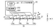
図1は、本発明に係る実施形態の磁場計測装置の構成例を表わすブロック図である。磁場計測装置1は、セルアレイ10、ポンプ光照射部20、プローブ光照射部30、及び検出ユニット40を有する。セルアレイ10は、複数のセル(10a,10b,10c,10d)を一列に並べて構成されている。各セルは、光を透過するガラス等の素材で形成され、セル内部に所定の原子からなる原子群が含まれた各々独立した物体である。この所定の原子は、円偏光によって励起状態となりスピン偏極する原子であり、例えば、リチウム(Li)、ナトリウム(Na)、カリウム(K)、ルビジウム(Rb)、セシウム(Cs)及びフランシウム(Fr)等のアルカリ金属である。なお、各セル内には、アルカリ金属の原子の他に、ヘリウム(He)、窒素(N)などのバッファーガスが含まれていてもよい。アルカリ金属の原子は、磁気を検出する際に気体の状態であればよく、常時気体の状態でなくてもよい。(Constitution)
FIG. 1 is a block diagram illustrating a configuration example of a magnetic field measurement apparatus according to an embodiment of the present invention. The magnetic field measurement apparatus 1 includes a
各セル(10a,10b,10c,10d)は、全て同じ形状である。図2(a)(b)は、本実施形態におけるセル10aを表わす図であり、図2(b)は、図2(a)に示すセル10aの左右を反転させた図である。図2(a)(b)に示すように、セル10aは、第2の面102と、第2の面102と対向する第3の面103とが直角三角形の三角柱の形状を有する。セル10aの第1の面101は、各セルが設置される設置面に対して傾斜し、ポンプ光が照射される面である。また、第2の面102はプローブ光が照射される面であり、第3の面103は第2の面102から入射したプローブ光がセル10aを透過して出射する面である。各セルは、図3に示すように、設置面Gに対する第1の面101の傾斜方向が全て同じ方向となるように隣接して設置面Gに配置される。この例では、第1の面101にポンプ光が照射され、第2の面102の側、つまりy軸方向からプローブ光が照射されるため、ポンプ光とプローブ光とに直交する矢印A方向の磁場の強度が検出対象となる。なお、本実施形態では、セルアレイ10のセルは一列に4つ並べられている例であるが、セルの数は複数であればよく、複数列であってもよい。また、設置面Gは、例えば、各セルが台座等に取り付けられた状態において各セルの下面が位置する平面、又は、各セルの下端が共通して接する平面として形成される。つまり、セルアレイ10の下端側において各セルの配列方向に広がる平面によって形成される。 Each cell (10a, 10b, 10c, 10d) has the same shape. 2A and 2B are diagrams showing the
ポンプ光照射部20は、ポンプ光照射手段の一例であり、円偏光成分を有するポンプ光を各セルに照射する。具体的には、図3に示すように、ポンプ光照射部20は、光源201と、光源201から出力される光を分配する分配機構202と、分配機構202から出力した光を各セルに導く光ファイバ等の伝送媒体203とを有する。
光源201は、無偏光成分を有するレーザー光を出力する。分配機構202は、光源201からのレーザー光をセルの数だけ分岐させ、分岐させた各レーザー光を、コリメートレンズ、偏光板、四分の一波長板等の光学部材(図示略)を出力端に有する伝送媒体203を介して、円偏光成分を有するポンプ光に変換して出力する。伝送媒体203から出力されたポンプ光は、各セルの第1の面101に入射すると、セル内のアルカリ金属原子はポンプ光によって同一方向にスピン偏極する。The pump
The light source 201 outputs laser light having a non-polarized component. The
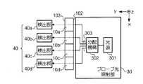
次に、プローブ光照射部30と検出ユニット40の詳細について図4を用いて説明する。図4は、図3に示すz軸方向から各セルを見たときのプローブ光照射部30と検出ユニット40と各セルとを表わしている。プローブ光照射部30は、プローブ光照射手段の一例であり、各セルに照射されるポンプ光と略直交するように直線偏光成分を有するプローブ光を照射する。プローブ光照射部30は、図4に示すように、光源301と、光源301から出力される光を分配する分配機構302と、分配機構302から出力した光を各セルに導く光ファイバ等の伝送媒体303とを有する。 Next, details of the probe
光源301は、無偏光成分を有するレーザー光を出力する。分配機構302は、光源301から出力したレーザー光をセルの数だけ分岐させ、分岐させた各レーザー光を、コリメートレンズ、偏光板、半波長板等の光学部材(図示略)を出力端に有する伝送媒体303を介して、直線偏光成分を有するプローブ光に変換して出力する。各セルに照射されたプローブ光は、各々のセルに入射し、各セルにおける磁場の影響によりセル内の原子が歳差運動を行った回転力に応じて偏光面が回転されてセルを透過し、各セルの第3の面103から出射する。なお、本実施形態では、ポンプ光とプローブ光とが略直交するように照射される例であるが、ポンプ光とプローブ光とが各セルの内部において交差していれば直交に限らない。 The
検出ユニット40の各検出部(40a,40b,40c,40d)は、検出手段の一例である。各検出部は、各セルの第3の面103から出射したプローブ光を偏光ビームスプリッター等によってP偏光成分とS偏光成分とに分離し、分離した光をフォトディテクタで受光する。各検出部は、フォトディテクタから出力されたP偏光成分とS偏光成分の光量に応じた電気信号を解析してプローブ光の偏光面の回転角度を求め、回転角度に応じた磁場の強度を求める。 Each detection part (40a, 40b, 40c, 40d) of the
(動作例)
次に、磁場計測装置1の動作例について説明する。
ポンプ光照射部20は、光源201からレーザー光を出力して分配機構202でポンプ光を分岐させ、分岐した各レーザー光を各出力端で円偏光成分を有するポンプ光に変換し、伝送媒体203を介して各セルの第1の面101に照射する。
各セルに照射されたポンプ光がセル内に入射すると、セル内のアルカリ金属原子はポンプ光によって励起されてスピン偏極し、検体からの磁場に応じて歳差運動を行う。(Operation example)
Next, an operation example of the magnetic field measurement apparatus 1 will be described.
The pump
When the pump light irradiated to each cell enters the cell, the alkali metal atoms in the cell are excited by the pump light to be spin-polarized and perform precession according to the magnetic field from the specimen.
プローブ光照射部30は、光源301からレーザー光を出力して分配機構302でプローブ光を分岐させ、分岐した各レーザー光を各出力端で直線偏光成分を有するプローブ光に変換し、伝送媒体303を介して各セルの第2の面102に照射する。各セルの第2の面102から入射したプローブ光は、セル内で歳差運動を行っている原子群によって偏光面が回転されて第3の面103の方へ進み、第3の面103から出射する。各セルの第3の面103から出射したプローブ光は、各セルに対応する検出部においてP偏光成分とS偏光成分に分離されて受光される。各検出部は、受光した各セルのP偏光成分とS偏光成分の光量に基づいてプローブ光の偏光面の回転角をセル毎に求め、各回転角に基づいて各セルにおける磁場の強度を求める。 The probe
上記実施形態では、各セルが隣接して配置されると共に、全てのセルに対してポンプ光及びプローブ光が同時に照射される構成となっているため、詳細に検体からの磁場を検出することができる。また、セルを隣接して配置し、ポンプ光とプローブ光の各光源から各セルに対してポンプ光及びプローブ光を分配して照射する構成であるため、セル毎にポンプ光とプローブ光の光源を設ける場合と比べて装置を小型化することができる。 In the above embodiment, the cells are arranged adjacent to each other, and the pump light and the probe light are simultaneously irradiated to all the cells, so that the magnetic field from the specimen can be detected in detail. it can. In addition, since the cells are arranged adjacent to each other and the pump light and the probe light are distributed and irradiated from the light sources of the pump light and the probe light to each cell, the light sources of the pump light and the probe light are provided for each cell. The apparatus can be reduced in size as compared with the case of providing.
<変形例>
本発明は、上述した実施形態に限定されるものではなく、以下のように変形させて実施してもよい。また、以下の変形例を組み合わせてもよい。<Modification>
The present invention is not limited to the above-described embodiment, and may be carried out by being modified as follows. Further, the following modifications may be combined.
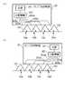
(1)上述した実施形態では、第2の面102と第3の面103が直角三角形のセルを用いて1方向の磁場を測定する例について説明したが、例えば、第2の面102と第3の面103が二等辺三角形のセルを用いて2方向の磁場を測定するようにしてもよい。この場合には、図5(a)に示すように各セル(10a,10b,10c,10d)を設置面Gに配置し、実施形態と同様に、セルの第1の面101にポンプ光を照射し、y軸方向、つまり第2の面102にプローブ光を照射することで、ポンプ光とプローブ光とに直交する矢印B1方向の磁場を検出する。また、図5(b)に示すように、第1の面101が傾斜する側と相対する側に設置面Gに対して傾斜する第4の面104、つまり、第1の面101の傾きを表わす係数の正負の符号が反対となる係数の傾きを有する第4の面104に対してもポンプ光を照射し、y軸方向にプローブ光を照射することで、ポンプ光とプローブ光とに直交する矢印B2方向の磁場を検出するように構成する。(1) In the above-described embodiment, an example in which the
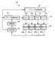
ここで、本変形例に係る磁場計測装置1Aの構成を表わすブロック図を図6に示す。図6において、実施形態と同様の構成については、実施形態と同様の符号を付している。図6に示すように、磁場計測装置1Aは、制御部50と駆動部60とを備えている点で実施形態とは異なる。本変形例では、ポンプ光照射部20、制御部50、及び駆動部60がポンプ光照射手段として機能する。磁場計測装置1Aは、セルアレイ10の上方にレール(図示略)を備え、レール上に設置された駆動部60においてポンプ光照射部20を回転可能に支持するように構成されている。なお、以下の説明において、ポンプ光照射部20のデフォルトの配置は、図7(a)に示す状態である。つまり、ポンプ光照射部20の伝送媒体203a,203b,203c,203dとセル10a,10b,10c,10dとが各々対応するように配置された状態である。 Here, a block diagram showing the configuration of the magnetic
駆動部60は、制御部50によって入力される制御信号に従ってポンプ光照射部20を回転させて移動させる。駆動部60は、第1の面101の方向からポンプ光を照射する制御信号が入力された場合には、図7(a)に示すデフォルトの配置でポンプ光照射部20を停止させておく。また、駆動部60は、第4の面104の方向からポンプ光を照射する制御信号が入力された場合には、ポンプ光照射部20の伝送媒体203d,203c,203b,203aとセル10a,10b,10c,10dとが各々対応する図7(b)に示す配置となるようにポンプ光照射部20の向きを回転させてレール上を移動させる。更に、駆動部60は、ポンプ光照射部20をデフォルトの配置に戻す制御信号が入力された場合には、ポンプ光照射部20を図7(a)に示すデフォルトの配置に戻す。 The
制御部50は、第1の面101方向からポンプ光を照射する第1処理を行って検体からの磁場を検出する第1検出処理と、第4の面104方向からポンプ光を照射する第2処理を行って検体からの磁場を検出する第2検出処理とを切り換えて行う。本変形例では、第1検出処理の終了後に第2検出処理を自動的に開始する。具体的には、制御部50は、第1の面101方向からポンプ光を照射することを指示する制御信号を駆動部60に入力し、ポンプ光照射部20から各セルの第1の面101に対してポンプ光を照射させると共に、プローブ光照射部30から各セルの第2の面102に対してプローブ光を照射させる。制御部50は、各検出部から出力される検出結果を受付けると第1検出処理を終了し、第2検出処理に移行する。 The
制御部50は、第4の面104方向からポンプ光を照射することを指示する制御信号を駆動部60に入力し、ポンプ光照射部20から各セルの第4の面104に対してポンプ光を照射させると共に、プローブ光照射部30から各セルの第2の面102に対してプローブ光を照射させる。制御部50は、各検出部から出力される検出結果を受付けると第2検出処理を終了し、ポンプ光照射部20をデフォルトの位置に戻す制御信号を駆動部50に入力する。 The
(2)上述した実施形態では、各セルの第2の面102及び第3の面103が直角三角形の形状である例を用いたが、ポンプ光が照射される第1の面101が設置面に対して一定の角度で傾斜されている多面体形状であればこれに限らない。また、上述した変形例(1)では、セルの第2の面102及び第3の面103が二等辺三角形のセルを例に説明したが、例えば、セルの第2の面102及び第3の面103が台形状のセルであってもよい。要は、各セルは、設置面に対して傾斜し光を透過させる第1の面101と、第1の面101と隣接し光を透過させる第2の面102と、第2の面102に対向し光を透過させる第3の面103と、光を透過させると共に第1の面101が傾斜する側と相対する側に設置面に対して傾斜する第4の面104とが形成されている多面体形状であればよい。(2) In the above-described embodiment, the example in which the
(3)上述した実施形態では、ポンプ光及びプローブ光の光源が一つの例を説明したが、セル毎のポンプ光とプローブ光の各光源を用いて、ポンプ光とプローブ光とを各セルに照射してもよい。(3) In the above-described embodiment, an example in which the light source of the pump light and the probe light is one has been described. However, the pump light and the probe light are supplied to each cell by using the light sources of the pump light and the probe light for each cell. It may be irradiated.
(4)上述した実施形態では、各検出部において各セルにおける磁場の強度を求める例を説明したが、各検出部で受光したP偏光成分とS偏光成分の光量に応じた電気信号を磁場計測装置1の外部の演算装置に出力し、当該演算装置においてプローブ光の回転角を算出し、回転角に応じた磁場の大きさを求めるようにしてもよい。(4) In the above-described embodiment, the example in which the magnetic field strength in each cell is obtained in each detection unit has been described. However, an electric signal corresponding to the amount of light of the P-polarized component and the S-polarized component received by each detection unit It is also possible to output to an arithmetic device outside the device 1, calculate the rotation angle of the probe light in the arithmetic device, and obtain the magnitude of the magnetic field according to the rotation angle.
(5)上述した変形例(1)では、一のポンプ光照射部20を用いて、各セルの第1の面101及び第4の面104にポンプ光を各々照射させる例であったが、ポンプ光照射手段の一例として、各セルの第1の面101にポンプ光を照射する第1処理を行う第1ポンプ光照射部と、各セルの第4の面104にポンプ光を照射する第2処理を行う第2ポンプ光照射部とを設け、第1ポンプ光照射部によって第1処理を行った後、第2ポンプ光照射部によって第2処理を行うようにしてもよい。(5) In the above modification (1), the pump
(6)上述した変形例(1)では、第1検出処理の終了後に第2検出処理を自動的に開始する例を説明したが、第1検出処理と第2検出処理の切り換えをユーザー操作に応じて行うように構成してもよい。この場合には、磁場計測装置1において、例えば、第1検出処理を指示する操作ボタンと第2検出処理を指示する操作ボタン等の操作手段を備えるように構成してもよい。制御部60は、操作手段を介したユーザー操作に応じて、第1検出処理と第2検出処理とを行うように駆動部50、ポンプ光照射部20、プローブ光照射部30、及び検出ユニット40を制御する。(6) In the modified example (1) described above, the example in which the second detection process is automatically started after the end of the first detection process has been described. However, switching between the first detection process and the second detection process can be performed by a user operation. You may comprise so that it may respond | correspond. In this case, the magnetic field measurement apparatus 1 may be configured to include operation means such as an operation button for instructing the first detection process and an operation button for instructing the second detection process. The
(7)上述した変形例(1)では、第1検出処理と第2検出処理の処理毎に、制御部50はプローブ光照射部30から各セルの第2の面102に対して照射させる例を説明したが、第1検出処理に続けて第2検出処理を自動開始する場合には、プローブ光照射部30からのプローブ光の照射を第2検出処理が終了するまで継続して行うようにしてもよい。(7) In the modification (1) described above, the
1,1A・・・磁場計測装置、10・・・セルアレイ、10a,10b,10c,10d・・・セル、20・・・ポンプ光照射部、30・・・プローブ光照射部、40・・・検出ユニット、40a,40b,40c,40d・・・検出部、50・・・制御部、60・・・駆動部、101・・・第1の面、102・・・第2の面、103・・・第3の面、104・・・第4の面、201,301・・・光源、202,302・・・分配機構、203,203a,203b,203c,203d,303・・・伝送媒体DESCRIPTION OF
Claims (3)
Translated fromJapanese前記セルアレイの各セルの前記第1の面にポンプ光を照射するポンプ光照射手段と、
前記各セルの前記第2の面に、当該セル内において前記ポンプ光と交差するようにプローブ光を照射するプローブ光照射手段と、
前記各セルの前記第3の面を透過したプローブ光を受光し、前記各セルにおける磁場を各々検出する検出手段と
を備えることを特徴とする磁場計測装置。A first surface that includes an atomic group composed of atoms excited by pump light, is inclined with respect to the installation surface and transmits light; a second surface that is adjacent to the first surface and transmits light; and A plurality of polyhedral-shaped cells having a third surface that transmits light transmitted through the second surface are arranged so that the inclination direction of the first surface is the same direction and at least one adjacent cell is in contact Cell array
Pump light irradiation means for irradiating the first surface of each cell of the cell array with pump light;
Probe light irradiating means for irradiating the second surface of each cell with probe light so as to intersect the pump light in the cell;
A magnetic field measuring apparatus comprising: detecting means for receiving probe light transmitted through the third surface of each cell and detecting a magnetic field in each cell.
前記ポンプ光照射手段は、前記各セルの前記第1の面にポンプ光を照射する第1処理と、前記第1処理に代えて、前記各セルの前記第4の面にポンプ光を照射する第2処理とを行うことを特徴とする請求項1に記載の磁場計測装置。Each of the cells has a fourth surface that transmits light and is inclined with respect to the installation surface on a side opposite to a side on which the first surface of the cell is inclined.
The pump light irradiation means irradiates the fourth surface of each cell with pump light instead of the first processing for irradiating the first surface of each cell with pump light and the first processing. The magnetic field measurement apparatus according to claim 1, wherein the second process is performed.
前記ポンプ光照射手段は、前記光源からの光を前記ポンプ光として前記各セルに分配して照射し、
前記プローブ光照射手段は、前記光源からの光を前記プローブ光として前記各セルに分配して照射することを特徴とする請求項1又は2に記載の磁場計測装置。The pump light irradiation means and the probe light irradiation means each have one light source,
The pump light irradiation means distributes and irradiates light from the light source to the cells as the pump light,
The magnetic field measurement apparatus according to claim 1, wherein the probe light irradiation unit distributes and irradiates light from the light source as the probe light to the cells.
Priority Applications (1)
| Application Number | Priority Date | Filing Date | Title |
|---|---|---|---|
| JP2011030537AJP2012168078A (en) | 2011-02-16 | 2011-02-16 | Magnetic field measuring device |
Applications Claiming Priority (1)
| Application Number | Priority Date | Filing Date | Title |
|---|---|---|---|
| JP2011030537AJP2012168078A (en) | 2011-02-16 | 2011-02-16 | Magnetic field measuring device |
Publications (1)
| Publication Number | Publication Date |
|---|---|
| JP2012168078Atrue JP2012168078A (en) | 2012-09-06 |
Family
ID=46972380
Family Applications (1)
| Application Number | Title | Priority Date | Filing Date |
|---|---|---|---|
| JP2011030537AWithdrawnJP2012168078A (en) | 2011-02-16 | 2011-02-16 | Magnetic field measuring device |
Country Status (1)
| Country | Link |
|---|---|
| JP (1) | JP2012168078A (en) |
Cited By (2)
| Publication number | Priority date | Publication date | Assignee | Title |
|---|---|---|---|---|
| US9500722B2 (en) | 2014-01-31 | 2016-11-22 | Seiko Epson Corporation | Magnetic field measurement apparatus |
| US11460523B2 (en)* | 2019-08-06 | 2022-10-04 | Hi Llc | Systems and methods having an optical magnetometer array with beam splitters |
- 2011
- 2011-02-16JPJP2011030537Apatent/JP2012168078A/ennot_activeWithdrawn
Cited By (2)
| Publication number | Priority date | Publication date | Assignee | Title |
|---|---|---|---|---|
| US9500722B2 (en) | 2014-01-31 | 2016-11-22 | Seiko Epson Corporation | Magnetic field measurement apparatus |
| US11460523B2 (en)* | 2019-08-06 | 2022-10-04 | Hi Llc | Systems and methods having an optical magnetometer array with beam splitters |
Similar Documents
| Publication | Publication Date | Title |
|---|---|---|
| JP6825241B2 (en) | Magnetic field measuring device, manufacturing method of magnetic field measuring device | |
| JP6825237B2 (en) | Magnetic field measuring device, manufacturing method of magnetic field measuring device | |
| CN102022977B (en) | Double-shaft MEMS scanning-based heterodyne interference system and method | |
| JP5373105B2 (en) | Miniature optical cell for miniaturized nuclear magnetic resonance gyroscope | |
| JPS58501597A (en) | optical device | |
| CN104919301A (en) | Systems and methods for measuring a profile characteristic of a glass sample | |
| JP2015143669A (en) | Magnetic field measuring device | |
| JP5434735B2 (en) | Cell unit, cell unit group and magnetic field measuring apparatus | |
| JP2012168078A (en) | Magnetic field measuring device | |
| JP5434782B2 (en) | Magnetic measuring device | |
| JP2012083311A (en) | Polarimeter | |
| JP2015099152A (en) | Magnetic field measuring apparatus | |
| JP5866940B2 (en) | Magnetic sensor device and magnetic measuring device | |
| JP5764949B2 (en) | Magnetic field measuring device | |
| JP2011232277A5 (en) | ||
| CN113625206A (en) | Dynamic mode conversion atomic magnetic field detection device | |
| CN109059892A (en) | Photon suspension gyroscope based on double-beam optical trap system | |
| JP2007057324A (en) | Optical fiber type measurement system | |
| JP2011237362A (en) | Magnetism measuring device | |
| KR101235274B1 (en) | Long-term stabilized heterodyne interferometer and readout sensor for biochemical fluidic channel using the interferometer | |
| JP2012213547A (en) | Magnetic field measurement device | |
| JP5747556B2 (en) | Magnetic field measuring apparatus and cell array | |
| JP2011106968A (en) | Magnetic measuring instrument | |
| JP5621240B2 (en) | Magnetic measuring device | |
| JP6024114B2 (en) | Magnetic field measuring device |
Legal Events
| Date | Code | Title | Description |
|---|---|---|---|
| A300 | Application deemed to be withdrawn because no request for examination was validly filed | Free format text:JAPANESE INTERMEDIATE CODE: A300 Effective date:20140513 |