JP2012166055A - Polyaxial bone screw with cam capture - Google Patents
Polyaxial bone screw with cam captureDownload PDFInfo
- Publication number
- JP2012166055A JP2012166055AJP2012108219AJP2012108219AJP2012166055AJP 2012166055 AJP2012166055 AJP 2012166055AJP 2012108219 AJP2012108219 AJP 2012108219AJP 2012108219 AJP2012108219 AJP 2012108219AJP 2012166055 AJP2012166055 AJP 2012166055A
- Authority
- JP
- Japan
- Prior art keywords
- shank
- protrusion
- assembly
- holding portion
- holding
- Prior art date
- Legal status (The legal status is an assumption and is not a legal conclusion. Google has not performed a legal analysis and makes no representation as to the accuracy of the status listed.)
- Pending
Links
- 210000000988bone and boneAnatomy0.000titleclaimsabstractdescription54
- 238000002513implantationMethods0.000claimsdescription5
- 238000012423maintenanceMethods0.000claimsdescription4
- 238000003780insertionMethods0.000claimsdescription3
- 230000037431insertionEffects0.000claimsdescription3
- 241000135309ProcessusSpecies0.000claims2
- 230000000712assemblyEffects0.000abstractdescription2
- 238000000429assemblyMethods0.000abstractdescription2
- 230000013011matingEffects0.000description11
- 238000000576coating methodMethods0.000description6
- 208000027418Wounds and injuryDiseases0.000description5
- 238000000034methodMethods0.000description5
- QORWJWZARLRLPR-UHFFFAOYSA-Htricalcium bis(phosphate)Chemical compound[Ca+2].[Ca+2].[Ca+2].[O-]P([O-])([O-])=O.[O-]P([O-])([O-])=OQORWJWZARLRLPR-UHFFFAOYSA-H0.000description5
- 238000009434installationMethods0.000description4
- 238000001356surgical procedureMethods0.000description4
- 229910000389calcium phosphateInorganic materials0.000description3
- 239000001506calcium phosphateSubstances0.000description3
- 235000011010calcium phosphatesNutrition0.000description3
- 239000007943implantSubstances0.000description3
- 229910052751metalInorganic materials0.000description3
- 239000002184metalSubstances0.000description3
- 230000007935neutral effectEffects0.000description3
- 239000004696Poly ether ether ketoneSubstances0.000description2
- 239000004699Ultra-high molecular weight polyethyleneSubstances0.000description2
- 230000009471actionEffects0.000description2
- 239000000853adhesiveSubstances0.000description2
- 230000001070adhesive effectEffects0.000description2
- 230000036782biological activationEffects0.000description2
- 239000011575calciumSubstances0.000description2
- 239000011248coating agentSubstances0.000description2
- 238000005520cutting processMethods0.000description2
- 229910052588hydroxylapatiteInorganic materials0.000description2
- 230000007246mechanismEffects0.000description2
- XYJRXVWERLGGKC-UHFFFAOYSA-Dpentacalcium;hydroxide;triphosphateChemical compound[OH-].[Ca+2].[Ca+2].[Ca+2].[Ca+2].[Ca+2].[O-]P([O-])([O-])=O.[O-]P([O-])([O-])=O.[O-]P([O-])([O-])=OXYJRXVWERLGGKC-UHFFFAOYSA-D0.000description2
- 229920002530polyetherether ketonePolymers0.000description2
- 238000003825pressingMethods0.000description2
- 230000008569processEffects0.000description2
- 238000000926separation methodMethods0.000description2
- 238000011282treatmentMethods0.000description2
- 229920000785ultra high molecular weight polyethylenePolymers0.000description2
- 238000003466weldingMethods0.000description2
- 229910014497Ca10(PO4)6(OH)2Inorganic materials0.000description1
- 239000002253acidSubstances0.000description1
- 239000000956alloySubstances0.000description1
- 229910045601alloyInorganic materials0.000description1
- 229910052586apatiteInorganic materials0.000description1
- 230000000975bioactive effectEffects0.000description1
- 239000003462bioceramicSubstances0.000description1
- 238000004891communicationMethods0.000description1
- 239000002131composite materialSubstances0.000description1
- 230000006835compressionEffects0.000description1
- 238000007906compressionMethods0.000description1
- 230000006378damageEffects0.000description1
- 201000010099diseaseDiseases0.000description1
- 208000037265diseases, disorders, signs and symptomsDiseases0.000description1
- 238000005553drillingMethods0.000description1
- 238000005530etchingMethods0.000description1
- XLYOFNOQVPJJNP-UHFFFAOYSA-MhydroxideChemical compound[OH-]XLYOFNOQVPJJNP-UHFFFAOYSA-M0.000description1
- 208000014674injuryDiseases0.000description1
- 229910052500inorganic mineralInorganic materials0.000description1
- 230000014759maintenance of locationEffects0.000description1
- 238000004519manufacturing processMethods0.000description1
- 239000000463materialSubstances0.000description1
- 239000011707mineralSubstances0.000description1
- VSIIXMUUUJUKCM-UHFFFAOYSA-Dpentacalcium;fluoride;triphosphateChemical compound[F-].[Ca+2].[Ca+2].[Ca+2].[Ca+2].[Ca+2].[O-]P([O-])([O-])=O.[O-]P([O-])([O-])=O.[O-]P([O-])([O-])=OVSIIXMUUUJUKCM-UHFFFAOYSA-D0.000description1
- 229920000642polymerPolymers0.000description1
- 229920002635polyurethanePolymers0.000description1
- 239000004814polyurethaneSubstances0.000description1
- 238000012545processingMethods0.000description1
- 238000002278reconstructive surgeryMethods0.000description1
- 239000007787solidSubstances0.000description1
- 238000005507sprayingMethods0.000description1
- 238000004544sputter depositionMethods0.000description1
- GBNXLQPMFAUCOI-UHFFFAOYSA-Htetracalcium;oxygen(2-);diphosphateChemical compound[O-2].[Ca+2].[Ca+2].[Ca+2].[Ca+2].[O-]P([O-])([O-])=O.[O-]P([O-])([O-])=OGBNXLQPMFAUCOI-UHFFFAOYSA-H0.000description1
- 238000004804windingMethods0.000description1
Images


Classifications
- A—HUMAN NECESSITIES
- A61—MEDICAL OR VETERINARY SCIENCE; HYGIENE
- A61B—DIAGNOSIS; SURGERY; IDENTIFICATION
- A61B17/00—Surgical instruments, devices or methods
- A61B17/56—Surgical instruments or methods for treatment of bones or joints; Devices specially adapted therefor
- A61B17/58—Surgical instruments or methods for treatment of bones or joints; Devices specially adapted therefor for osteosynthesis, e.g. bone plates, screws or setting implements
- A61B17/68—Internal fixation devices, including fasteners and spinal fixators, even if a part thereof projects from the skin
- A61B17/70—Spinal positioners or stabilisers, e.g. stabilisers comprising fluid filler in an implant
- A61B17/7001—Screws or hooks combined with longitudinal elements which do not contact vertebrae
- A61B17/7035—Screws or hooks, wherein a rod-clamping part and a bone-anchoring part can pivot relative to each other
- A61B17/7037—Screws or hooks, wherein a rod-clamping part and a bone-anchoring part can pivot relative to each other wherein pivoting is blocked when the rod is clamped
- A—HUMAN NECESSITIES
- A61—MEDICAL OR VETERINARY SCIENCE; HYGIENE
- A61B—DIAGNOSIS; SURGERY; IDENTIFICATION
- A61B17/00—Surgical instruments, devices or methods
- A61B17/56—Surgical instruments or methods for treatment of bones or joints; Devices specially adapted therefor
- A61B17/58—Surgical instruments or methods for treatment of bones or joints; Devices specially adapted therefor for osteosynthesis, e.g. bone plates, screws or setting implements
- A61B17/68—Internal fixation devices, including fasteners and spinal fixators, even if a part thereof projects from the skin
- A61B17/70—Spinal positioners or stabilisers, e.g. stabilisers comprising fluid filler in an implant
- A61B17/7001—Screws or hooks combined with longitudinal elements which do not contact vertebrae
- A61B17/7032—Screws or hooks with U-shaped head or back through which longitudinal rods pass
Landscapes
- Health & Medical Sciences (AREA)
- Orthopedic Medicine & Surgery (AREA)
- Life Sciences & Earth Sciences (AREA)
- Neurology (AREA)
- Surgery (AREA)
- Heart & Thoracic Surgery (AREA)
- Engineering & Computer Science (AREA)
- Biomedical Technology (AREA)
- Nuclear Medicine, Radiotherapy & Molecular Imaging (AREA)
- Medical Informatics (AREA)
- Molecular Biology (AREA)
- Animal Behavior & Ethology (AREA)
- General Health & Medical Sciences (AREA)
- Public Health (AREA)
- Veterinary Medicine (AREA)
- Surgical Instruments (AREA)
Abstract
Description
Translated fromJapanese本発明は、骨外科、特に脊椎外科に使用される多軸骨用ねじに関する。そのようなねじは、骨用ねじのシャンクに対して回動する受容部又はヘッドを有しており、それによりその受容部がシャンクに対していかなる角度にも位置付け構成できるようになっている。 The present invention relates to a polyaxial bone screw used in bone surgery, particularly spinal surgery. Such a screw has a receptacle or head that rotates relative to the shank of the bone screw so that the receptacle can be positioned and configured at any angle with respect to the shank.
多くの脊椎外科手術手順においては、骨に対して、特に脊椎に沿った椎骨に対して各種の埋設物を固定する必要がある。傷害又は病気により傷ついた又は弱った脊椎を支持するために、例えば固体硬質ロッド又はよりフレキシブルな延設部材等の脊椎に沿って延びた延設部材がしばしば利用されている。そのような延設部材は、ある椎骨により支えられなければならない一方で、他の椎骨を支えなければならない。 In many spine surgical procedures, it is necessary to fix various implants to the bone, particularly to the vertebrae along the spine. Extension members that extend along the spine, such as solid rigid rods or more flexible extension members, are often used to support a spine that has been damaged or weakened by injury or disease. Such extension members must be supported by one vertebra while supporting other vertebrae.
椎骨支持を提供する最も一般的な機構は、まず複数の骨用ねじを複数の骨に埋め込み、そしてそれらの骨用ねじが延設部材を支持するか、又はそれらが延設部材に支持されるというような機構である。このタイプの骨用ねじは、そのシャンクに対して固定されたヘッド又は受容部を有している。そのような固定骨用ねじにおいては、ヘッドをシャンクに対して動かすことができず、ロッドは、ヘッド内に置かれるためにうまく位置付けされる必要があった。これは、ときに大変困難であり、また不可能なときもあった。故に、多軸骨用ねじが一般的には好まれている。 The most common mechanism for providing vertebral support is to first embed a plurality of bone screws into a plurality of bones and the bone screws support the extension member or they are supported by the extension member It is such a mechanism. This type of bone screw has a head or receptacle fixed to the shank. In such fixed bone screws, the head could not be moved relative to the shank and the rod had to be well positioned to be placed in the head. This was sometimes very difficult and sometimes impossible. Therefore, polyaxial bone screws are generally preferred.
多軸骨用ねじによれば、受容部のシャンクに対する所望の回転位置が決定されるまで、受容部をシャンクに対して回転させることができる。その後、ロッドが受容部に差し込まれ、最終的に受容部は、シャンクに対して特定の位置でロック又は固定される。 The polyaxial bone screw allows the receptacle to be rotated relative to the shank until the desired rotational position of the receptacle relative to the shank is determined. Thereafter, the rod is inserted into the receiving part, and finally the receiving part is locked or fixed at a specific position with respect to the shank.
各種の多軸又は回動ヘッド骨用ねじアセンブリが利用できる。骨用ねじアセンブリの1つのタイプとしては、その内部にロッドを載置できる開放型ヘッド又は受容部がある。そして、閉被トップ又はプラグを使用して、ねじの受容部内にそのロッドを掴持するようにしている。 Various multi-axis or pivot head bone screw assemblies are available. One type of bone screw assembly is an open head or receptacle in which a rod can be placed. A closure top or plug is then used to grip the rod within the screw receptacle.
本発明の多軸骨用ねじアセンブリは、上端部と骨に固定するためのねじ切り下部とを有する一般的延設本体であるシャンクを備えている。上端部は、更に、側方延設突起を有している。シャンクは、上方に導いて受容部内に導くことができる。受容部は、上部及び基部から成っており、上部は、開放しており溝を有している。基部には、空洞及び下部開口を部分的に画定する内側座面がある。上部の溝は、空洞と連通している。下部開口は、受容部空洞内にシャンク上部が受け入れられるだけの大きさ及び形状を有している。 The polyaxial bone screw assembly of the present invention comprises a shank, which is a generally extended body having an upper end and a threaded lower portion for securing to the bone. The upper end portion further has a laterally extending protrusion. The shank can be guided upward into the receiving part. The receiving part is composed of an upper part and a base part, and the upper part is open and has a groove. The base has an inner seating surface that partially defines a cavity and a lower opening. The upper groove communicates with the cavity. The lower opening is sized and shaped to receive the upper shank within the receptacle cavity.
骨用ねじアセンブリは、また、ある実施形態においては連続閉塞リング状保持部であり、他の実施形態においては開放又は不連続リングであるような保持部構造を備えている。保持部は、上記側方延設突起と摩擦係合する少なくとも一面を有する内側傾斜スロット又はカムトラックを有しており、それにより保持部はシャンクに固定される。 The bone screw assembly also includes a retainer structure that is a continuous occlusion ring retainer in some embodiments and an open or discontinuous ring in other embodiments. The holding portion has an inner inclined slot or cam track having at least one surface frictionally engaged with the laterally extending protrusion, whereby the holding portion is fixed to the shank.
故に、本発明の目的は、全ての部分が合体したままで分離しない埋設物を提供し、各構成部が協働することにより不本意な分解を防止できる全体構造を創生するような方法で組み立てられる、軽量で簡単な形状の多軸骨用ねじを提供し、骨埋め込み工具のための十分な摩擦又は把持面を備えて容易に確実に互いに固定し、また骨に固定できるというような特徴を有した多軸骨用ねじを提供し、使用が容易であり、特に意図した使用に適した装置及び方法を提供することにある。なお、その装置は、比較的製作費が安価で、使用に適している。 Therefore, an object of the present invention is to provide a buried object that does not separate with all parts joined together, and in such a way as to create an overall structure that can prevent unintentional disassembly by the cooperation of each component. Features that provide assembled, lightweight and simply shaped polyaxial bone screws that can be easily and securely secured to each other and secured to bone with sufficient friction or gripping surfaces for bone implantation tools It is an object of the present invention to provide a device and method that are easy to use and particularly suitable for the intended use. The device is relatively inexpensive to manufacture and is suitable for use.
本発明の他の目的及び利点は、添付図面と共に考慮されるべき以下の詳細な説明から明らかになるであろう。詳細な説明には例証及び例示で説明される実施の形態が記載されている。 Other objects and advantages of the present invention will become apparent from the following detailed description, which should be considered in conjunction with the accompanying drawings. The detailed description includes embodiments described by way of illustration and example.
図面は、この明細書の一部を構成し、本発明の実施の形態を含み、その各種目的や特徴を図示するものである。 The drawings constitute a part of this specification, include embodiments of the present invention, and illustrate various objects and features thereof.
要求に応じて、本発明の詳細な実施形態がここに開示される。しかしながら、開示された実施形態は発明の単なる例にすぎず、発明は各種の形態で具現化できるであろう。ゆえに、ここに開示された特定の構造的及び機能的詳細は、限定的に解釈されるべきではなく、単に請求の範囲の基礎として、また当業者が、実質的に適切に具体化された構造に本発明を多様的に採用できるように教示するための代表的な基礎として解釈されるべきである。また、この明細書において、頂、底、上方及び下方等の語句は、多様な図面に対する整合のため使用されると共にそのような機器に通常適用される内包を意味しており、実際に使用される応用及び協働接続部材における骨取付けアセンブリの位置づけを制限するようなものではない。 As required, detailed embodiments of the present invention are disclosed herein. However, the disclosed embodiments are merely examples of the invention, and the invention may be embodied in various forms. Accordingly, the specific structural and functional details disclosed herein are not to be construed as limiting, but merely as a basis for the claims and by those skilled in the art which are substantially appropriately embodied. It should be construed as a representative basis for teaching the present invention so that it can be used in various ways. Further, in this specification, terms such as top, bottom, upper and lower are used for alignment with various drawings and mean inclusions usually applied to such devices, and are actually used. It is not intended to limit the position of the bone attachment assembly in the application and the cooperating connection member.
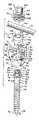
図1−8を参照すると、参照番号1は、概して、本発明の多軸骨用ねじ装置又はアセンブリの一実施形態を示している。アセンブリ1は、上部8と一体化したねじ切り本体6を有するシャンク4と、受容部10と、閉塞又は一体化保持部構造又はリング12とを備えている。シャンク4、受容部10及び保持部構造12は、シャンク本体6が椎骨(図示せず)に埋め込まれる前に、工場で組み立てられることが望ましい。 Referring to FIGS. 1-8, reference numeral 1 generally indicates one embodiment of a polyaxial bone screw device or assembly of the present invention. The assembly 1 comprises a shank 4 having a threaded
図1は、更に閉被構造18を示しており、その閉被構造18は、保持部12を偏倚させて受容部80と摩擦による固定接触させるシャンク上部8に対して、ロッド21のような縦長接続部材を押し付けて偏倚させるためのものであり、それによりロッド21が椎骨(図示せず)に対して固定される。受容部10及びシャンク4は、以下のように協働する。すなわち、受容部10とシャンク4は、左右と前後の両方の角度における選択範囲内で、互いの角度、咬合状態又は回転配置において、如何なる状態でも固定可能となっており、それにより、埋め込み作業の終了間際にそれらが互いにロックして固定されるまで、受容部10がシャンク4に対してフレキシブルに咬み合った状態をとることができる。 FIG. 1 further shows a
シャンク4は、図1、4、5及び8に最もうまく示される通り、棒状であり、シャンク本体6は、上部8に近接して位置するネック部26の近傍から本体6の先端部28に延びると共に半径方向外側に延びる螺旋巻き骨埋め込みねじ部24を有している。使用中、掴み及び進行のためのねじ部24を利用する本体6は、据え付け又は駆動工具(図示せず)により、先端部28から椎骨(図示せず)に埋め込まれ、椎骨内に入り込んでいき、それによりネック部26近くまで椎骨に埋め込まれる。なお、この内容は以降の段落でより完全に記述される。シャンク4は、参照文字Aにより一般的に規定される長手回転軸を有している。 The shank 4 is rod-shaped as best shown in FIGS. 1, 4, 5 and 8, and the
ネック部26は、シャンク本体6から軸方向上方に延びている。ネック部26は、ねじ切り本体6の近接上部32の半径よりも短い半径を有していてもよい。ネック部26から軸方向に更に延びているのは、シャンク上部8であり、それは、本体6が椎骨に埋め込まれるときに、ねじ切り本体上部32から一定距離で、つまりそのような椎骨から一定距離で配設された接続又はキャプチャー装置を供する。 The
シャンク上部8は、シャンク4と受容部10の間の多軸接続を実現し、シャンク4の上部8が受容部10内に掴持される。上部8は、一般的に、保持部座部33と、突起又はタブ36の形状の側方伸延部を有する実質的円筒部34と、工具嵌合構造40と、上端面42とを備える。駆動工具(図示せず)が、工具嵌合構造40に嵌合する構造となっており、それによりシャンク本体6を回転させつつ駆動して椎骨内に進めるためのソケット及び咬合突起を形成している。図に示される実施形態においては、工具嵌合構造40は、ねじ切りシャンク本体6及びシャンク上部8の双方と同軸の六角形状延設ヘッドの形をしている。本発明の他の実施形態では、例えば一対の対向側方突起のような複数の突起を有することができる。 The shank
シャンク4の上端面42は、シャンク4が受容部10に対して如何なる向きでもよい状態で、骨用ねじアセンブリ1が図7に示すように組み立てられるときに、ロッド21に当接、又はそれと積極的に咬合するために、図面に示すように、好ましくは曲面又はドーム形状をしている。ある実施形態においては、面42は滑らかである。本発明の実施化にあたって必要なことではないが、面42は筋又は刻みが付けられて、面42とロッド21との間の摩擦積極咬合を更に強化してもよい。 The
図面に示されたシャンク4は、カニューレ加工されており、軸Aに沿ってシャンク4の長さ全体に渡って延びている小中央内腔44を有している。内腔44は、シャンク4の内側円筒壁45により画定され、また、シャンク先端部28において第一円形開口46を有し、上面42のところで第二円形開口48を有している。内腔44は、ねじ切り本体6及びキャプチャー構造外側面34と同軸である。内腔44は、シャンク本体6の挿入の前に椎骨(図示せず)に挿入される一本のワイヤ(図示せず)をシャンク4の内部に通すための通路の役割を果たす。 The shank 4 shown in the drawing is cannulated and has a small
図4及び5を参照すると、シャンク上部8の保持部座部33は、シャンクの軸Aに垂直に配設されると共に、後に詳述するように保持部12と摩擦咬合するために十分な半径方向伸延幅を有して底から受容部10内に導かれ得るような大きさ及び形状を有した実質的平面環状上面50を備えている。座部33は、平坦環状面50の端又はリム54から延び、下方のシャンク本体6の方に曲面で延びてネック部26に達する実質球形状面52を更に備えている。球面52が示されているが、その面は、円錐でもよいし、他の非球面であってもよいことに注意すべきである。この開示の実施形態においては、面52は、以下に議論されるように、座部33が保持部12と係合したときに、保持部12の外側面と面一になっている。 Referring to FIGS. 4 and 5, the
シャンク上部8の円筒部34は、座部33と工具嵌合構造40の間に配設されている。部位34は、上面又は狭いレッジ56と、レッジ56から座部33の環状面50までに渡る実質的平滑円筒面58とを備えている。面58は、軸Aの周りに均一である。突起36は、レッジ56近傍の面58から側方に延びる。突起36は、上面60と、底面61と、一対の対向及び実質平行側面62及び63と、外側曲面64とを有している。曲面64は、円筒面であり、面58と同軸である。上面60は、工具嵌合構造40から延び、いくつかの実施形態においては、図に示すように、外側面64の方へ行くにつれて座部33の方へ、つまり下方へ僅かに傾いていてもよい。底面61は、円筒面58から外側面64まで拡がる。図4に最適に示されているように、底面61は、好ましくは、側面62から側面63に向って下側へ下がるような角度で傾き、又は傾斜しており、それにより、より詳細に後述するように、保持部12のカムトラック傾斜面と完全に摩擦係合するようになっている。底面61は、普通に座面50と平行に配設されていてもよく、それによれば低面61の端部が最終的に保持部12のカムトラックと摩擦係止する、ということが予見できる。 The
骨との生物学的活性化インターフェースをとるために、ねじ切りシャンク本体76は、コーティングされ、孔があけられ、多孔性にされ、又は他の処理が行われてもよい。そのような処理としては、限定されはしないが、プラズマスプレイコーティングや他の金属コーティング、また例えば燐酸カルシウムのコーティング、又は、スパッタリング、砂葺き、酸エッチング等によるシャンク表面の凹凸化、孔あけ、窪み付けなどがあり、それらにより骨の内部成長及び表面成長が促される。いくつかの金属コーティングは、骨の内部成長の足場としての役割を果たす。バイオセラミック燐酸カルシウムコーティングとしては、アルファ燐酸三カルシウム及びベータ燐酸三カルシウム(Ca3(PO4)2)、燐酸四カルシウム(Ca4P2O9)、非晶質燐酸カルシウム及び水酸化リン灰石(Ca10(PO4)6(OH)2)があるが、それらには限定はされない。例えば水酸化リン灰石によるコーティングについていえば、水酸化リン灰石はミネラル含有量に関して骨と化学的に同質であり、生体活性化作用があるものとして認められており、それで骨の内部成長のサポートのみならず、積極的に骨の接合に関与するものであるから、そのコーティングは望ましいものといえる。The threaded shank body 76 may be coated, perforated, made porous, or otherwise treated to provide a biological activation interface with bone. Such treatments include, but are not limited to, plasma spray coating or other metal coatings, for example calcium phosphate coatings, or surface shank irregularities, drilling, dents by sputtering, sanding, acid etching, etc. And the like, which promote bone ingrowth and surface growth. Some metal coatings serve as a scaffold for bone ingrowth. Bioceramic calcium phosphate coatings include alpha tricalcium phosphate and beta tricalcium phosphate (Ca3 (PO4 )2 ), tetracalcium phosphate (Ca4 P2 O9 ), amorphous calcium phosphate and apatite hydroxide (Ca10 (PO4 )6 (OH)2 ), but is not limited thereto. For example, with respect to coating with hydroxyapatite, hydroxyapatite is chemically homogenous with bone in terms of mineral content and is recognized as having a bioactive effect, so that The coating is desirable because it actively participates in bone bonding as well as support.
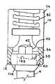
図1及び5を参照すると、受容部10は、一般的には方形化U型外観をしており、部分的円筒内側形状と部分的咬合外側形状を有しているが、外側形状は部分的に円筒形にすることができる。受容部10は、一対の起立アーム72及び74と一体化したいくらかの曲面を有した又は球面の基部102を有しており、それにより、U形状受け台が形成され、アーム72及び74の間にU形状溝76が規定され、そのときロッド21を滑合的に動作可能に受け入れるため、ロッド21の半径と実質的に同じ半径を有する上部開口77及び下側座部78を備えるようにしている。 1 and 5, the
アーム72及び74の各々は、内側円筒形状を画定すると共に、部分螺旋巻きガイド/進行構造82を含む内側面80を有している。図示の実施形態においては、ガイド/進行構造82は、後に更に詳細に説明されるように、回転に際して閉被構造18の同種構造と組み合うように構成された部分螺旋巻き相互固定角形ねじである。しかしながら、ガイド/進行構造82は、閉被トップを回転させつつ案内してアーム72及び74間で下方に進めるための、フランジ形状、片ねじれねじ状、反角度保有ねじ状、又は他のねじ状、または非ねじ状の螺旋巻き不連続進行構造であってもよいことが予見できるであろう。 Each of the
工具係合開口85がアーム72及び74の表面上に、又は表面を貫通して設けられており、シャンク4及び保持部構造12の組み付けの間や、シャンク本体6の椎骨(図示せず)への埋め込みの間に、受容部10を保持するために使用され得る。更に、アーム72及び74の各々は、その外側面に、V型の、又は下部切除の工具係合溝88及び90を有しており、シャンク本体6の埋め込みの間、及び/又は引き続きのロッド21及び閉被構造18の埋め込みの間、溝88及び90内に受け入れられる突起を有する保持工具(図示せず)により、受容部10を保持するために使用される。工具受入れ溝又は開口は、各種の形状や大きさを有するように構成でき、受入れアーム72及び74の他の場所にも配設できることが予見できるであろう。
受容部10のU形状溝の下に位置してそれと連通しているのは、基部70の内側面100により画定されるチャンバー又は空洞98であり、その空洞98は、U形状溝76に向けて上方に開放している。内側面100は、実質的に球状であり、少なくともその一部が第一の半径を有する部分内側球形状座面102を形成している。面102は、以下により完全に記述されるように、保持部構造12と嵌合するような大きさと形状を有している。 Located below and in communication with the U-shaped groove of the
基部70は、制限ネック部103を更に備えており、そのネック部は、第二の半径Rを有し、基部50の空洞98及び下方外側部106と連通する内腔104を画定している。内腔104は、受容部10の回転軸Bと同軸で揃っている。ネック部103とそれに関連の内腔104は、保持部構造12の半径寸法(第一半径)よりも小さくなる(第二半径)ような大きさと形状になっており、それによりネック部103のところで保持部構造12に対して制限されており、保持部構造12が受容部10内に載置されたときには、その保持部構造12が空洞98を抜けて受容部10の下方外側部106へ落ちてしまうことのないようになっている。 The base 70 further includes a limiting
内側面100は、保持部構造12を導いて空洞98内に収容する延設上方導入窪み部107を更に画定している。導入窪み部107は、一般的に垂直に受容部10内に配設され、溝76と空洞98の間に延びてそれらと連通しており、それにより保持部構造12を上方から上部開口77を通して空洞内に導入することを容易にし、また受容部10の球面壁100が比較的大きな半径を有して受容部の基部70の厚さと強さを増すようにしている。しかしながら、導入窪み部107は必ずしも必要ではない。 The
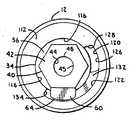
保持部構造又はリング12は、シャンク上部8を掴み、その上部8を受容部10内に保持するのに使用される。図2,3及び8に最適に示されているが、保持部12は、シャンク4に関連の回転軸Aと同じ動作中心軸を有しているが、保持部構造12がシャンク4から分離されたときには、図1に示すように、その回転軸は、軸Cとして識別される。保持部構造12は、その保持部構造12の上面112から底面114までを貫通する中央内腔110を有している。底面114は、実質的に平坦で、軸Cに対して垂直に配設されている。第一内側円筒面116は、内腔110の実質部分を画定している。円筒面116は、シャンク上部8の円筒面部34を摺動的に受け入れることができるような大きさと形状を有している。スロット(溝孔)、一般記述としての118は、内側面116内、かつ上面112及び底面114のところに形成される。スロット118は、貫通スロット、一般記述としての120と、カムトラック、一般記述としての122を含むものとして記述される。貫通スロット120は、カムトラック122と連通してそれと協働している。貫通スロット120は、受容部空洞98内で保持部12をシャンク上部18に据え付けるときに、シャンク上部の突起36が通過してそれを受け入れることができるような大きさと形状を有している。カムトラック122は、シャンク上部8の突起36の底面61と摩擦係合するような大きさと形状を有しており、受容部12の底面114は、シャンク上部8の座部33の上面50の上に置かれる。 The holding part structure or
特に図2及び3を参照すると、貫通スロット120は、円筒面116と同軸の内側円筒面126で画定される。円筒面126は、また部分的にカムトラック122を画定している。スロット120のところでは、面126は、上面112から底面114の間に渡って延びている。貫通スロット120は、更に、対向する側面128及び130によっても画定されており、それらの面は軸Cに平行である。側面128は、上面112から底面114の間に渡って延びている。側面130は、底面114のところから始まって、カムトラック122を部分的に画定する傾斜面132のところで終わっている。カムトラック122は、更に、軸Cと実質的に平行に走る面又は停止部134まで延びる内側円筒面126によっても画定される。つまり、カムトラック122は、円筒面126の一部、傾斜面又は斜面132、及び停止部134により画定されるということになる。斜面132は、面130から停止部134に向うにつれて上面112の方向へ昇るように傾斜している。面132の傾斜度は、突起36の底面61の傾斜度と実質的に一致している。本発明によるいくつかの実施形態においては、傾斜面132と突起部底面61の双方又は一方は、凹凸、リッジ、又は他の処理形状を有しており、それにより保持部12の突起36に対して摩擦でのロック作用を更に助長している。 With particular reference to FIGS. 2 and 3, the through
シャンク上部8のレッジ56と協働する、保持部12の上面112は、工具嵌合構造40の周りに面を形成し、その面は、駆動工具(図示せず)のための安定した載置面となっている。図に示された僅かに曲った上面112は、駆動工具のよりうまく咬み合うようにいくらかの窪みを呈している。上面112は、平坦であってもよいし、又は保持工具を受け入れるための窪み又は開口を有していてもよいことは、予見できるであろう。 The
保持部12は、受容部の部分球形状座面102と嵌合するような大きさと形状を有し、面102についての第一半径をほぼ等しい第三半径を有する半径方向外側部分球形状面144を備えている。保持部構造の第三半径は、受容部10のネック部103の第二半径よりも大きい。必要なことではないが、外側部分球形状面144は、刻み付き面やその他の面のように高摩擦面であってもよいことが予見できる。 The retaining
アセンブリ1と共に利用される延設ロッド又は縦長部材21は、脊椎再構成外科手術で利用される埋設物のうち各種が考えられるが、通常、均一の直径を有する円筒面146と一般の滑らかな面を有する円筒延設構造を有するものである。縦長接続部材21は、金属、合金、又は、ポリエーテルエーテルケトン(PEEK)、超高分子量ポリエチレン(UHMWP)、ポリウレタン、及び複合体のような可塑性重合体もその1つである他の適した材料で作られる。図示のロッド21は、好ましくは、受容部10のU形状溝76の底部近傍に滑合的に載置されるような大きさと形状を有しており、通常動作の間、下方座部78のところであって溝76の底部より僅かに上方に位置付けされる。特に、ロッド21は、通常、シャンク上面42と直接的又は当接的に係合し、ドーム型のシャンク上面42に対して偏倚され、その結果、アセンブリ1が完全に組み立てられたとき、シャンク4を下方、つまり受容部10の基部70の方向へ偏倚させる。このようになるためには、シャンク上面42は、保持部構造12が受容部の空洞100の底部に滑合的に載置されるとき、溝76のスペース内に少なくとも僅かにでも入り込んでいなければならない。ロッド21がシャンク上面42をしっかりと下方に押すことにより、シャンク4及び保持部12は、受容部10に対して所定位置にロックされて保持される。 The extending rod or
図1を参照して、閉被構造又は閉被トップ18については、起立アーム72及び74に対する適した咬み合い構造を有し、本発明との関係で使用される閉被構造であれば多くの異なる種類が考えられる。示された実施形態においては、閉被トップ18は、2つの離反アーム72及び74の間で回転しつつ受け入れられる。図示された閉被構造18は、上方に延びた破断ヘッド160を有する一般的円筒形状基部158を備えている。基部158は、アーム72及び74の表面のガイド/進行構造82に対して係止するような大きさ及び形状を有し、かつ位置付けされる螺旋巻きガイド/進行構造161を有しており、それにより、時計まわりに回転すると、閉被構造18は回転して進んで受容部10内に入り、また、特に、アーム72及び74を拡げることなく、U形状溝76の上部又は上方開放部77を覆ってロッド21を捕える。本発明により利用されるガイド/進行構造161は、各種の形状をとることができ、それには図示されている実質的角ねじのほかに、本出願人の米国特許第6,726,689号明細書に記述されているものも含まれる。なお、当該明細書は、援用されてここに開示されているものとする。 Referring to FIG. 1, the closure structure or
閉被構造18が進むと、ロッド21を動作可能に偏倚させ、ロッド21に対してトルクによる圧力を与える。それによりロッド21は、下方へ導かれ、溝76内で上方に延びるシャンク上端面42に突き当たる。シャンク上面42の下方への偏倚により、ロッド21と面42との間で動作可能な摩擦係合が生じ、また保持部構造12を受容部10の基部70の方へ促すということになる。それにより、保持部構造外側球面144が受容部10の部分内側球形状座面102に対して摩擦力を持って固定的に載置され、また、シャンク4及び保持部構造12が、受容部10に対して選択された固定位置に固定される。 As the
示された実施形態においては、閉被構造破断ヘッド160は、保持部12を受容部10内に適切に載置するように設計された所定のトルクで破断するような大きさ及び形状を有したネック部164のところで基部158に固定されている。破断ヘッド160は、閉被構造18にトルクを与えて回転させるための駆動工具(図示せず)の伝統的な嵌合ソケットタイプヘッドを受け入れるような大きさ及び形状を有した外側嵌合面165を有している。破断ヘッド160は、また、操作工具を動作可能に受け入れるための中央内腔又は他の駆動もしくは操作開口(図示せず)を有していてもよい。 In the illustrated embodiment, the closure
閉被構造18は、また、取外し工具嵌合構造を有しており、本実施形態では、基部158内に配設された、例えば六角形同軸開口のような開口168として想像線で描かれている。開口168は、破断ヘッド160が基部158から取り除かれた後にアクセス可能である。開口168は、螺旋巻きガイド/進行構造161と同軸であり、またアレンレンチタイプの六角工具のような駆動工具を受け入れるように設計されており、必要であれば、据え付けの後に閉被構造基部158を回転させてそれを取り外すことができるようになっている。開口168は、各種の工具係合形状をとることができ、また、一対の離反開口、又は左手用ねじ切り内腔、又は簡易離脱係合段差内腔、又はトルクス開口、又は多小葉性開口等のような各種形状を有した1つ以上の開口であってもよい。 The
特に図5−8を参照すると、多軸骨用ねじアセンブリ1が本発明に従って使用される状態になる前に、典型的には最初に、リング状保持部12が、受容部U形状溝76に挿入され、又は上方から導入され、そして垂直導入窪み部107を介して空洞98に入れられ、そして受容部10の内側面100内に配設される。その後、保持部構造12は、概ね90度回転させられて受容部10と同軸とされ、そして図5に示すように受容部10の座面102と摺動的に係合した状態で載置される。図6を参照すると、シャンクキャプチャー構造8がネック部103により画定される内腔104を介して受容部10内に挿入され、つまり下方から導入される。そのとき受容部10内に配設されている保持部構造12は、シャンクキャプチャー構造8と同軸に揃っているので、突起36が貫通スロット120に受け入れられてそれを通過し、最終的には保持部12の底面114が座部33の面50と係合することとなる。そして保持部12は、突起36がカムトラック122に受け入れられるまで、シャンクの軸Aの周りに回転させられる。図7及び8を参照すると、保持部12が回転し、突起36が停止部134の方へ移動すると、突起底面61は、カムトラック122の傾斜面132と摩擦係合し、それにより保持部12は突起36と座部33の間に摩擦ロックされ、そして保持部12はシャンク4と固定同軸関係の状態に至る。好ましくは、シャンク4及び/又は保持部12が保持されてそれらのロック摩擦係合が成立するまで正確にそれらを回転させる工程が行われる工場での設定後の構造にように、シャンク4及び/又は保持部12は回転させられて完全に咬合する。図7を参照すると、シャンク上部8が受容部10内で保持部12と咬合させるために回転している間、シャンク工具嵌合構造40と動作的に嵌合するためのソケットを形成する内側面182を有する保持工具180が、そのシャンク上部8を保持するために使用される。示されてはいないが、保持部構造12は、一対の小さな開口のような工具用特徴部を有していてもよく、それにより保持部12は、突起36がカムトラック122に沿って回転している間、しっかりと保持されるようにしてもよいことに注意すべきである。キャプチャー構造8の保持部構造12に対する永久的でしっかりとした咬合は、接着剤、スポット溶接、変形等を使用することにより、更に支持される。このとき、シャンク4と保持部12の双方が、受容部10に対して回転可能で旋回(回動)可能な係合状態にあり、一方、シャンク上部8と、受容部10の下部開口、つまりネック部103は、協働し、シャンク本体6が受容部10に対して回動可能な関係にあるように維持する。保持部12のみが、受容部球形状座面102と摺動的に係合する状態にある。シャンク上端41及びシャンク本体6は、受容部10とは隔てられた関係にある。シャンク本体6は、受容部10に対して前後及び左右に実質的に角度をもって回転することが可能であり、それにより実質的にユニバーサルジョイントやボールジョイントが提供される。 With particular reference to FIGS. 5-8, before the polyaxial bone screw assembly 1 is ready to be used in accordance with the present invention, typically the ring-shaped
使用されるときには、アセンブリ1は、六角形延設ヘッドの形状をした工具嵌合構造40との嵌合により、シャンク4を押し込んで回転させる駆動工具(図示せず。しかし、工具180のソケット182と類似のソケットを有する)を使用したシャンク4の回転により、典型的には、椎骨(図示せず)のような骨にねじ込まれる。好ましくは、駆動工具が嵌合構造40と嵌合するとき、その端部がレッジ56と嵌合し、また曲面的な保持部上面112の一部と係合することもできるので、駆動工具の更なるグリップ力が提供される。 When used, the assembly 1 is driven by a drive tool (not shown; however,
椎骨(図示せず)に対するストレスを最小にするよう、その骨は予め穴あけされ、椎骨に対するシャンク4の位置及び角度のためのガイドを提供するために挿入されるカニューレ44のための形状をしたガイドワイヤ(図示せず)を有していてもよい。ガイドワイヤをガイドとしてタップを使用することにより、更なるタップ穴を設けてもよい。そして、まず底部開口46にワイヤを通し、上部開口48から取り出すことによるカニューレ内腔44を利用して、アセンブリ1が、ガイドワイヤを覆って通される。そして、そのワイヤを位置ガイドとして使用して、シャンク4を椎骨に押し込む。 In order to minimize stress on the vertebra (not shown), the bone is pre-drilled and shaped guide for
ロッド21は、最終的に受容部U形状溝76内に位置付けされ、そして閉被構造又はトップ18が挿入されてアーム72及び74の間を進行し、それによりロッド21を偏倚させ、つまり押圧する。閉被構造18の破断ヘッド160は、所定のトルク、例えば90から120インチポンドまでのトルクで、捻じられ、ロッド21を下方に促す。シャンク上端面42は、シャンク4と受容部10の間でどの程度の回転があろうともほぼ同じ量だけ溝76内を上方にほぼ同様に延びるように丸められているのであるから、また、面42は、U形状溝76内を上方に延びるような大きさをしているのであるから、閉被構造18が下方のロッド21の方へ偏倚してそれに当たるとき、面42は、ロッド21と係合し、下方の受容部10の基部70の方へ押される。シャンク4への下方圧力により、今度は保持部構造12が下方の受容部座面102の方へ促され、保持部構造面144が受容部座面102と摩擦係合の状態に至る。閉被構造18がロッド21を押圧すると、ロッド21は、シャンクを押圧することとなる。このときシャンク4にしっかりと取り付けられている保持部構造12が、今度は下方に促され、受容部10に摩擦をもってしっかりと固着することとなり、それにより受容部10及びロッド21に対して所望の角度でシャンク本体6が固定されることとなる。 The
アセンブリ1及び関連ロッド21及び閉被構造18を外すことが必要な場合、アレンレンチタイプの駆動工具(図示せず)を使用し、開口168と嵌合させ、反時計回りに回転させると、受容部10内で基部168が回転して反対方向に進むので、分解はそれにより達成できる。そして、アセンブリ1の分解は、既述の組み立ての手順とは反対の順で達成できる。 If it is necessary to remove the assembly 1 and associated
図9−17を参照すると、参照番号201は、本発明による多軸骨用ねじ装置又はアセンブリの他の実施形態を示している。アセンブリ200は、上部208と一体化したねじ切り本体206を更に有したシャンク204と、受容部210と、開放型保持部構造又はリング212とを備えている。シャンク204、受容部210及び保持部構造212は、好ましくは、シャンク本体206を椎骨(図示せず)に埋め込む前に工場で組み立てられる。 Referring to FIGS. 9-17,
図9は、更に閉被構造218を示しており、その閉被構造218は、保持部212を偏倚させて受容部210と摩擦による固定接触させるシャンク上部208に対して、ロッド221のような縦長接続部材を押し付けて偏倚させるためのものであり、それによりロッド221が椎骨(図示せず)に対して固定される。受容部210及びシャンク204は、以下のように協働する。すなわち、受容部210とシャンク204は、左右と前後の両方の角度における選択範囲内で、互いの角度、咬合状態又は回転配置において、如何なる状態でも固定可能となっており、それにより、埋め込み作業の終了間際にそれらが互いにロックして固定されるまで、受容部210がシャンク204に対してフレキシブルに咬み合った状態をとることができる。 FIG. 9 further shows a
シャンク204は、図9及び15−17に最もうまく示される通り、棒状であり、そのシャンク本体206は、アセンブリ1について既に記述したシャンク本体6と実質的に同様の螺旋巻き骨埋込みねじ部224を有している。シャンク204は、参照文字Eにより一般的に規定される長手回転軸を有している。 The
シャンクネック部226は、シャンク本体206から軸方向上方に延びている。ネック部226から軸方向に更に延びているのは、シャンク上部208であり、それは、本体206が椎骨に埋め込まれるときに、ねじ切り本体206から一定距離で、つまりそのような椎骨(図示せず)から一定距離で配設された接続又はキャプチャー装置を供する。 The
アセンブリ1と同様、アセンブリ201のシャンク上部208は、シャンク204と受容部210との間で多軸接続を実現し、シャンク204の上部108が受容部210に受け入れられるように構成されている。シャンク上部208は、上側環状面231、外側円筒面232及び下側環状面233を有した実質的に円筒形の保持部座部230を概して備えている。座部230は、ネック部226から半径方向である外側へ延びている。上面231及び下面233は、ともに軸Eに対して実質的に垂直に配設されている。ネック部226の上であって、下側環状座面233の近傍に配置されているのは、突起又はタブ236の形態の側方延設部である。上側環状面231から軸方向に上方に延びているのは、上端面242を有する工具嵌合構造240である。駆動工具(図示せず)は、工具嵌合構造240の周りに嵌められ、シャンク本体206を椎骨に回転させつつ押し込むためのソケット及び嵌合突起を形成するように構成されている。具体的には、図面に示された実施形態において、工具嵌合構造240は、ねじ切りシャンク本体206及びシャンク上部208の双方と同軸の六角形状延設ヘッドの形状をしている。上側環状面231は、駆動工具(図示せず)のための座面を提供している。シャンク204の上端面242は、骨用ねじアセンブリ201が図17に示すように組み立てられて、シャンク204が受容部210に対していかなる方向を向いていようとも、ロッド221と当接し、又は積極的に係合するように、好ましくは、図面に示す通り、丸まった、又はドームの形状をしている。ある実施形態においては、面242は、滑らかである。本発明の実施化に必要なことではないが、面242には、その面242とロッド221との間の摩擦による積極的な係合の度合いを増すために、筋や刻みを付けるようにしてもよい。 Similar to assembly 1, the shank
図示のシャンク204は、カニューレ加工されており、軸Eに沿ってシャンク204の長さ全体に渡って延びている小中央内腔244を有している。内腔244は、ねじ切り本体206及びキャプチャー構造外側面232と同軸である。内腔244は、シャンク本体206の挿入の前に椎骨(図示せず)に挿入される一本のワイヤ(図示せず)をシャンク204の内部に通すための通路の役割を果たし、ワイヤは、シャンク本体206を椎骨(図示せず)に挿入するためのガイドとなっている。骨との生物学的活性化インターフェースを実現するために、ねじ切りシャンク本体206は、アセンブリ1のシャンク本体6に関して既に記述されているように、被膜され、孔があけられ、多孔性にされ、又は他の処理が行われてもよい。 The illustrated
特に図15を参照して、シャンク上部208は、圧縮された保持部212がそれに接続された状態で、受容部210内へ下方から導入できるような大きさと形状を有している。保持部座部は、後により詳細に記述されるように、保持部212と摩擦係合するのに十分な、非圧縮時の、又は中立時の半径方向幅を有している。動作位置にあるシャンクに取り付けられたときには、保持部212は、シャンク上部208の円筒面232及び下側環状面233の双方に係合する。円筒面232が示されているが、その面は、多角形、球面、円錐面又は他の曲面のような他の形状をしていてもよい。開示された実施形態においては、以下に議論されるように、座230が保持部212と係合するときに、上面231は保持部212の上面と面一になる。下側環状面233の近傍でネック部226から側方に延びる突起236は、下側又は底面248と、底面248に対して実質的に垂直に配設される側面250と、底面248と側面248の間に延びてそれらを接続する曲面又は斜面252とを有している。側面250は、実質的に軸Eと平行に配設される。面248、250及び252は、円筒形であり、ネック部226と同軸の外側曲面254も画定している。面252は、後により詳細に記述されるように、側面250から下方へある角度で向いている斜面又は傾斜となっており、それにより保持部212のカムトラック傾斜面と完全に摩擦係合するようになっている。既述のアセンブリ1についてと同様、突起236の他の面も斜面又は傾斜とし、保持部212のカムトラックと摩擦ロック係合させるようにしてもよい。 With particular reference to FIG. 15, the shank
図9及び15−17を参照して、受容部210は、アセンブリ1の受容部10と実質的に同様のものである。特に、例えば、受容部210は、基部270、アーム272及び274、U形状溝276、ガイド/進行構造282、球形状座面302により部分的に画定される空洞298、基部下方外側部306に開口する内腔304を画定するネック部303を備えており、それらは、骨用ねじアセンブリ1に関して既に記述した基部70、アーム72及び74、U形状溝76、ガイド/進行構造82、空洞98、球形状座面102、ネック部103、内腔104及び下方外側部106のそれぞれと同じ、又は実質的に同様のものである。 With reference to FIGS. 9 and 15-17, the receiving
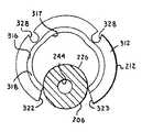
保持部構造又はリング212は、シャンク上部208を掴み、その上部208を受容部210内に保持するのに使用される。図10−14に最適に示されているが、保持部212は、シャンク204に関連の回転軸Eと同じ動作中心軸を有している。保持部構造212は、その保持部構造212の上面312から底面314までを貫通する中央内腔310を有している。底面314は、実質的に平坦で、軸Cに対して垂直に配設されている。第一内側又は上側円筒面316は、内腔310の一部を画定している。第二内側円筒面317は内腔310の残部を規定しており、その直径は面316の直径よりも小さい。環状座部又は段差318は、第一円筒面316を第二円筒面に接続させており、その座部318は、上面312及び下面315と実質的に平行に配設され、円筒面316及び317に対して垂直に配設されている。座部318は、シャンク上部208の下側環状面233と完全に係合するような大きさ及び形状を有している。円筒面316は、シャンク上部208の円筒面部232の周りに摺動的に受け入れられるような大きさ及び形状を有しており、一方、円筒面317は、シャンクネック部226の周りに摺動的に受け入れられるような大きさ及び形状を有している。カムトラック又はスロット320が、内側面317に形成されている。カムトラック320は、シャンク上部208上の保持部212の受容部空洞298内への据付けの間、シャンク上部208の突起236を受け入れるような大きさと形状を有している。カムトラック320は、軸Eに対して傾いて、又は傾斜しており、突起面248及び252と摩擦係合するような大きさと形状を有しており、そのとき保持部212の座部又は段差318は、シャンク上部208の下側面233上に最終的に摩擦係合するようになっている。 A retainer structure or
上述のように、保持部212は、開放型又は不連続のリングの形状をしており、上面312及び底面314の双方に渡る端面322及び323を有している。カムトラック320は、端面322のところで開放しており、突起236を受け入れるような大きさと形状を有している。保持部212は、受容部球形状座部302と摺動的に係合するような大きさと形状の外側部分球面326を更に備えている。外側面326に形成されているのは、上面312と底面314の間を走る一対の延設溝328であり、以下により詳細に記述されるように、その溝328により、保持部212のシャンク204への据付けの間、端面322及び323から離れたところでの開放又は拡張が可能となる。本発明のいくつかの実施形態においては、突起236の1以上の面及び/又はカムトラック320を画定する面は、凹凸、リッジ、又は他の処理形状を有しており、それにより保持部212の突起236に対する摩擦でのロック作用を更に助長している。 As described above, the holding
シャンク上部208の上面又はレッジ231と協働する、保持部212の上面312は、駆動工具(図示せず)のための安定座面である工具嵌合構造240の周りに面を形成する。必要なことではないが、外側部分球形状面326は、刻み付き面のような高摩擦面であってもよいことは予見できる。 The
アセンブリ201と共に利用される延設ロッド又は縦長部材221は、アセンブリ1の21に関して記述したように、脊椎再構成外科手術で利用される埋設物のうち各種が考えられる。ロッド221は、通常、シャンク上面242と直接的又は当接的に係合し、ドーム型のシャンク上面242に対して偏倚され、その結果、アセンブリ201が完全に組み立てられたとき、シャンク204を下方、つまり受容部210の基部270の方向へ偏倚させる。このようになるためには、シャンク上面242は、保持部構造212が受容部の空洞302の底部に滑合的に載置されるとき、溝276のスペース内に少なくとも僅かにでも入り込んでいなければならない。ロッド221がシャンク上面242をしっかりと下方に押すことにより、シャンク204及び保持部212は、受容部210に対して所定位置にロックされて保持される。 The extension rod or
図9及び17において、閉被構造又は閉被トップ218については、起立アーム272及び274に対する適した咬み合い構造を有し、本発明との関係で使用される閉被構造であれば多くの異なる種類が考えられる。示された実施形態においては、閉被トップ218は、2つの離反アーム272及び274の間で回転可能に受け入れられる。図示された閉被構造218は、実質的に円筒形であり、アーム272及び274の表面のガイド/進行構造282に対して係止するような大きさ及び形状を有し、かつ位置付けされる螺旋巻きガイド/進行構造361を有しており、それにより、時計まわりに回転すると、閉被構造218は回転して進んで受容部210内に入り、また、特に、アーム272及び274を拡げることなく、U形状溝276の上部又は上方開放部を覆ってロッド221を掴持する。本発明により利用されるガイド/進行構造361は、各種の形状をとることができ、それには図示されている実質的角ねじのほかに、本出願人の米国特許第6,726,689号明細書に記述されているものも含まれる。なお、当該明細書は、援用されてここに開示されているものとする。 9 and 17, the closure structure or
閉被構造218が進むと、ロッド221を動作可能に偏倚させ、ロッド221に対してトルクによる圧力を与える。それによりロッド221は、下方へ導かれ、溝276内で上方に延びるシャンク上端面242に突き当たる。シャンク上面242の下方への偏倚により、ロッド221と面242との間で動作可能な摩擦係合が生じ、また保持部構造212を受容部210の基部270の方へ促すということになる。それにより、保持部構造外側球面326が受容部210の部分内側球形状座面302に対して摩擦力を持って固定的に載置され、また、シャンク204及び保持部構造212が、受容部210に対して選択された固定位置に固定される。 As the
示された実施形態においては、閉被構造は、上面364と、対向する実質平坦な底面365を有している。上面364には、駆動工具(図示せず)を受け入れることができる大きさと形状の星形状又はTorxの開口として示される内側駆動特徴部366が形成されている。開口366は、各種の工具係合形状をとることができ、また、一対の離反開口、又は左手用ねじ切り内腔、又は簡易離脱係合段差内腔、六角駆動又は多小葉性開口等のような、各種形状の1つ以上の開口であってもよい。 In the illustrated embodiment, the closure structure has a
特に図12−14を参照すると、多軸骨用ねじアセンブリ201が本発明に従って使用される状態になる前に、最初にリング状保持部212が、ネック部226のシャンク204上に挿入される。図13を参照すると、保持部端面322及び323が押されて互いに離され、それにより保持部212は拡がり、保持部上面312がシャンク上部208と相対した状態で、シャンクネック部226を内側壁316及び317内に受け入れる。各拡張溝328は、保持部212が拡がると、圧縮される。図14に示すように、一旦、シャンク204のネック部が端面322及び323を過ぎると、保持部212は、中立で、非拡張状態の実質円形構成に戻る。そして、端面322及び323が互いの方へ押されて接触するまで、又はほとんど接触するまでのところまでいくと、保持部212は圧縮されることとなる。そのような圧縮された状態で、シャンク上部208及び圧縮保持部212が受容部210内のネック部303のところへ上方から又は下方から導入される。一旦、シャンク上部208及び保持部212の双方が、受容部空洞298内に入ってしまうと、圧力は保持部212から解放され、図15に示すように、端面322及び323が元の離反中立位置に戻る。これにより、保持部外側面326は、受容部座面302と摺動的に係合することとなる。図16を参照すると、シャンクキャプチャー構造208が降下されて保持部212に入れられ、突起236が端面322及び端面323の間に配設される。そして保持部212又はシャンク204が、シャンク204の軸Eの周りに回転させられ、突起236が面322のところでカムトラック320に入り込む。図16及び17を参照すると、保持部212又はシャンク208が回転すると、突起236が傾斜したカムトラック320に沿って移動し、最終的にはトラックが終わるか、又は突起が、トラック320を画定する面、及び保持部環状座面318と完全に摩擦係合し、そしてその保持部環状座面318とは、シャンク下側環状面233と完全に摩擦係合する。それにより突起236と下側座部又は面233の間で保持部212がロックされ、そしてその保持部212は、シャンク204と固定同軸関係の状態に至る。好ましくは、シャンク204及び/又は保持部212が保持されてそれらのロック摩擦係合が成立するまで正確にそれらを回転させる工程が行われる工場での設定後の構造にように、シャンク204及び/又は保持部212は回転させられて完全に咬合する。示されてはいないが、保持部構造212は、一対の小さな開口のような工具用特徴部を有していてもよく、それにより受容部212は、突起236がカムトラック320に沿って回転している間、しっかりと保持されるようにしてもよいことに注意すべきである。キャプチャー構造208の保持部構造212に対する永久的でしっかりとした咬合は、接着剤、スポット溶接、変形等を使用することにより、更に支持される。このとき、シャンク204と保持部212の双方が、受容部210に対して回転可能で旋回(回動)可能な係合状態にあり、一方、シャンク上部208と、受容部210の下部開口、つまりネック部は、協働し、シャンク本体206が受容部210に対して回動可能な関係にあるように維持する。保持部212のみが、受容部球形状座面302と摺動的に係合する状態にある。シャンク本体206は、受容部210に対して前後及び左右に実質的に角度をもって回転することが可能であり、それにより実質的にユニバーサルジョイントやボールジョイントが提供される。 With particular reference to FIGS. 12-14, the ring-shaped
使用されるときには、アセンブリ201は、六角形延設ヘッドの形状をした工具嵌合構造240との嵌合により、シャンク204を押し込んで回転させる駆動工具(図示せず)を使用したシャンク204の回転により、典型的には、椎骨(図示せず)のような骨にねじ込まれる。 When used, the
椎骨(図示せず)に対するストレスを最小にするよう、その骨は予め穴あけされ、椎骨に対するシャンク204の位置及び角度のためのガイドを提供するために挿入されるカニューレ244のための形状をしたガイドワイヤ(図示せず)を有していてもよい。ガイドワイヤをガイドとしてタップを使用することにより、更なるタップ穴を設けてもよい。そして、カニューレ内腔244を利用して、アセンブリ201が、ガイドワイヤを覆って通される。そして、そのワイヤを位置ガイドとして使用して、シャンク204を椎骨に押し込む。 In order to minimize stress on the vertebra (not shown), the bone is pre-drilled and shaped guide for the
ロッド221は、最終的に受容部U形状溝276内に位置付けされ、そして閉被構造又はトップ218が挿入されてアーム272及び274の間を進行し、それによりロッド221を偏倚させ、つまり押圧する。シャンク上端面242は、シャンク204と受容部210の間でどの程度の回転があろうともほぼ同じ量だけ溝276内を上方にほぼ同様に延びるように丸められているのであるから、また、面242は、U形状溝276内を上方に延びるような大きさをしているのであるから、閉被構造218が下方のロッド221の方へ偏倚してそれに当たるとき、面242は、ロッド221と係合し、下方の受容部210の基部270の方へ押される。シャンク204への下方圧力により、今度は保持部構造212が下方の受容部座面302の方へ促され、保持部面326が受容部座面302と摩擦係合の状態に至る。閉被構造218がロッド221を押圧すると、ロッド221は、シャンクを押圧することとなる。このときシャンク204にしっかりと取り付けられている保持部構造212が、今度は下方に促され、受容部210に摩擦をもってしっかりと固着することとなり、それにより受容部210及びロッド221に対して所望の角度でシャンク本体6が固定されることとなる。 The
アセンブリ201及び関連ロッド221及び閉被構造218を外すことが必要な場合、アレンレンチタイプの駆動工具(図示せず)を使用し、開口366と嵌合させ、反時計回りに回転させると、受容部210内で閉被構造218が回転して反対方向に進むので、分解はそれにより達成できる。そして、アセンブリ201の分解は、既述の組み立ての手順とは反対の順で達成できる。 If it is necessary to remove
ここでは本発明のいくつかの形態について、図面で示すと共に記述してきたが、記述されまた示された特定の形態又は特定の部材配置には限定されないと理解されるべきである。 Although several forms of the invention have been illustrated and described herein with reference to the drawings, it should be understood that the invention is not limited to the specific forms or arrangements of parts described and shown.
Claims (10)
Translated fromJapanese(b)開放溝を画定すると共に空洞を部分的に画定する座面を伴った基部を有する受容部であって、前記開放溝が前記空洞と連通し、前記空洞が、前記シャンク上部を受け入れることができる大きさ及び形状を有する開口を介して前記基部の外側部と連通するような受容部と、
(c)中央内腔を画定すると共に、前記突起を受け入れて摩擦係合する傾斜カムトラックの画定する内側面を有する保持部と、
を備えることを特徴とする多軸骨用ねじアセンブリ。(A) a shank having a main body for fixing to a bone, an upper portion, and at least one laterally extending protrusion at a position away from the upper surface of the upper portion;
(B) a receiving portion having a base with a seating surface defining an open groove and partially defining a cavity, wherein the open groove communicates with the cavity and the cavity receives the shank top; A receiving portion communicating with the outer portion of the base portion through an opening having a size and shape capable of
(C) a holding portion having an inner surface defined by an inclined cam track that defines a central lumen and receives and frictionally engages the protrusion;
A screw assembly for a polyaxial bone, comprising:
(a)前記上端から離れた位置にあり、前記シャンクから側方に突き出した突起と、
(b)上面、底面、外側面及び内側面を有した閉塞型保持部と、
を備えた多軸骨用ねじアセンブリの改良であって、
前記外側面及び内側面の双方は、前記上面と前記底面の間に渡り、前記内側面は、前記上面及び前記底面に対してある角度をもって配設された少なくとも1つのカム面を伴ったスロットを有し、前記外側面は、前記受容部と摺動可能な関係にあり、前記カム面は前記突起と摩擦係合することを特徴とする多軸骨用ねじアセンブリの改良。A multiplicity for surgical implantation comprising a shank having an upper end, a threaded body for insertion into a bone, an outer open groove adapted to receive an elongated connection member, and a receptacle having a shank receiving opening In the axial bone screw assembly,
(A) a protrusion at a position away from the upper end and protruding laterally from the shank;
(B) a closed type holding portion having an upper surface, a bottom surface, an outer surface and an inner surface;
An improvement of a polyaxial bone screw assembly comprising:
Both the outer surface and the inner surface span between the top surface and the bottom surface, and the inner surface has a slot with at least one cam surface disposed at an angle with respect to the top surface and the bottom surface. An improved polyaxial bone screw assembly, wherein the outer surface is in a slidable relationship with the receptacle and the cam surface is frictionally engaged with the protrusion.
(a)前記上端から離れた位置にあり、前記シャンクから側方に突き出した突起と、
(b)前記上端から離れた位置にあると共に前記上端と前記突起の間にあり、前記シャ
ンクから半径方向に延びた座面と、
(c)上面、底面、外側面及び内側面を有した閉塞型保持部と、
を備えた多軸骨用ねじアセンブリの改良であって、
前記外側面及び内側面の双方は、前記上面と前記底面の間に渡り、前記内側面は、内部に形成されたカムトラックを有し、当該トラックは、前記上面及び前記底面に対してある角度をもって走り、前記外側面は、前記受容部と摺動可能な関係にあり、前記カムトラックは前記突起と摩擦係合し、前記シャンク座面は前記保持部上面と摩擦係合することを特徴とする多軸骨用ねじアセンブリの改良。A multiplicity for surgical implantation comprising a shank having an upper end, a threaded body for insertion into a bone, an outer open groove adapted to receive an elongated connection member, and a receptacle having a shank receiving opening In the axial bone screw assembly,
(A) a protrusion at a position away from the upper end and protruding laterally from the shank;
(B) a seating surface located at a position away from the upper end and between the upper end and the protrusion and extending in a radial direction from the shank;
(C) a closed type holding portion having an upper surface, a bottom surface, an outer surface and an inner surface;
An improvement of a polyaxial bone screw assembly comprising:
Both the outer surface and the inner surface span between the top surface and the bottom surface, the inner surface has a cam track formed therein, and the track is at an angle with respect to the top surface and the bottom surface. The outer surface is in a slidable relationship with the receiving portion, the cam track is frictionally engaged with the protrusion, and the shank seat surface is frictionally engaged with the upper surface of the holding portion. Improved multiaxial bone screw assembly.
Applications Claiming Priority (4)
| Application Number | Priority Date | Filing Date | Title |
|---|---|---|---|
| US88164107P | 2007-01-22 | 2007-01-22 | |
| US60/881,641 | 2007-01-22 | ||
| US12/009,130 | 2008-01-16 | ||
| US12/009,130US8257398B2 (en) | 2003-06-18 | 2008-01-16 | Polyaxial bone screw with cam capture |
Related Parent Applications (1)
| Application Number | Title | Priority Date | Filing Date |
|---|---|---|---|
| JP2009547262ADivisionJP2010516388A (en) | 2007-01-22 | 2008-01-18 | Multiaxial bone screw with cam capture |
Publications (1)
| Publication Number | Publication Date |
|---|---|
| JP2012166055Atrue JP2012166055A (en) | 2012-09-06 |
Family
ID=39499176
Family Applications (2)
| Application Number | Title | Priority Date | Filing Date |
|---|---|---|---|
| JP2009547262APendingJP2010516388A (en) | 2007-01-22 | 2008-01-18 | Multiaxial bone screw with cam capture |
| JP2012108219APendingJP2012166055A (en) | 2007-01-22 | 2012-05-10 | Polyaxial bone screw with cam capture |
Family Applications Before (1)
| Application Number | Title | Priority Date | Filing Date |
|---|---|---|---|
| JP2009547262APendingJP2010516388A (en) | 2007-01-22 | 2008-01-18 | Multiaxial bone screw with cam capture |
Country Status (6)
| Country | Link |
|---|---|
| US (1) | US8257398B2 (en) |
| EP (1) | EP2114271A4 (en) |
| JP (2) | JP2010516388A (en) |
| AU (1) | AU2008209568A1 (en) |
| CA (1) | CA2674392C (en) |
| WO (1) | WO2008091542A2 (en) |
Families Citing this family (74)
| Publication number | Priority date | Publication date | Assignee | Title |
|---|---|---|---|---|
| US7833250B2 (en) | 2004-11-10 | 2010-11-16 | Jackson Roger P | Polyaxial bone screw with helically wound capture connection |
| US8353932B2 (en)* | 2005-09-30 | 2013-01-15 | Jackson Roger P | Polyaxial bone anchor assembly with one-piece closure, pressure insert and plastic elongate member |
| US8876868B2 (en) | 2002-09-06 | 2014-11-04 | Roger P. Jackson | Helical guide and advancement flange with radially loaded lip |
| US7621918B2 (en)* | 2004-11-23 | 2009-11-24 | Jackson Roger P | Spinal fixation tool set and method |
| US7377923B2 (en) | 2003-05-22 | 2008-05-27 | Alphatec Spine, Inc. | Variable angle spinal screw assembly |
| US7776067B2 (en) | 2005-05-27 | 2010-08-17 | Jackson Roger P | Polyaxial bone screw with shank articulation pressure insert and method |
| US8398682B2 (en)* | 2003-06-18 | 2013-03-19 | Roger P. Jackson | Polyaxial bone screw assembly |
| US8366753B2 (en) | 2003-06-18 | 2013-02-05 | Jackson Roger P | Polyaxial bone screw assembly with fixed retaining structure |
| US7766915B2 (en) | 2004-02-27 | 2010-08-03 | Jackson Roger P | Dynamic fixation assemblies with inner core and outer coil-like member |
| US8926670B2 (en) | 2003-06-18 | 2015-01-06 | Roger P. Jackson | Polyaxial bone screw assembly |
| US7967850B2 (en) | 2003-06-18 | 2011-06-28 | Jackson Roger P | Polyaxial bone anchor with helical capture connection, insert and dual locking assembly |
| AU2004266737B2 (en)* | 2003-08-20 | 2010-05-13 | Warsaw Orthopedic, Inc. | Multi-axial orthopedic device and system, e.g. for spinal surgery |
| US7503924B2 (en) | 2004-04-08 | 2009-03-17 | Globus Medical, Inc. | Polyaxial screw |
| US8475495B2 (en) | 2004-04-08 | 2013-07-02 | Globus Medical | Polyaxial screw |
| US8926672B2 (en) | 2004-11-10 | 2015-01-06 | Roger P. Jackson | Splay control closure for open bone anchor |
| US9980753B2 (en) | 2009-06-15 | 2018-05-29 | Roger P Jackson | pivotal anchor with snap-in-place insert having rotation blocking extensions |
| US8444681B2 (en) | 2009-06-15 | 2013-05-21 | Roger P. Jackson | Polyaxial bone anchor with pop-on shank, friction fit retainer and winged insert |
| US9168069B2 (en) | 2009-06-15 | 2015-10-27 | Roger P. Jackson | Polyaxial bone anchor with pop-on shank and winged insert with lower skirt for engaging a friction fit retainer |
| US7901437B2 (en) | 2007-01-26 | 2011-03-08 | Jackson Roger P | Dynamic stabilization member with molded connection |
| US7951198B2 (en)* | 2005-05-10 | 2011-05-31 | Acumed Llc | Bone connector with pivotable joint |
| US10792074B2 (en)* | 2007-01-22 | 2020-10-06 | Roger P. Jackson | Pivotal bone anchor assemly with twist-in-place friction fit insert |
| US8979904B2 (en) | 2007-05-01 | 2015-03-17 | Roger P Jackson | Connecting member with tensioned cord, low profile rigid sleeve and spacer with torsion control |
| AU2010260521C1 (en) | 2008-08-01 | 2013-08-01 | Roger P. Jackson | Longitudinal connecting member with sleeved tensioned cords |
| EP2745789B1 (en) | 2008-10-30 | 2017-04-19 | Depuy Spine Inc. | Systems for delivering bone cement to a bone anchor |
| FR2942951B1 (en)* | 2009-03-12 | 2012-03-30 | Euros Sa | SPINAL IMPLANT WITH LOCKING BALL JOINT |
| US11229457B2 (en) | 2009-06-15 | 2022-01-25 | Roger P. Jackson | Pivotal bone anchor assembly with insert tool deployment |
| US9668771B2 (en) | 2009-06-15 | 2017-06-06 | Roger P Jackson | Soft stabilization assemblies with off-set connector |
| CN103826560A (en) | 2009-06-15 | 2014-05-28 | 罗杰.P.杰克逊 | Polyaxial Bone Anchor with Socket Stem and Winged Inserts with Friction Fit Compression Collars |
| US11464549B2 (en) | 2009-06-15 | 2022-10-11 | Roger P. Jackson | Pivotal bone anchor assembly with horizontal tool engagement grooves and insert with upright arms having flared outer portions |
| US8998959B2 (en) | 2009-06-15 | 2015-04-07 | Roger P Jackson | Polyaxial bone anchors with pop-on shank, fully constrained friction fit retainer and lock and release insert |
| EP2485654B1 (en) | 2009-10-05 | 2021-05-05 | Jackson P. Roger | Polyaxial bone anchor with non-pivotable retainer and pop-on shank, some with friction fit |
| US12383311B2 (en) | 2010-05-14 | 2025-08-12 | Roger P. Jackson | Pivotal bone anchor assembly and method for use thereof |
| AU2011324058A1 (en)* | 2010-11-02 | 2013-06-20 | Roger P. Jackson | Polyaxial bone anchor with pop-on shank and pivotable retainer |
| EP2460484A1 (en)* | 2010-12-01 | 2012-06-06 | FACET-LINK Inc. | Variable angle bone screw fixation assembly |
| US8636774B2 (en) | 2010-12-17 | 2014-01-28 | Spinal Usa, Inc. | Spinal implant apparatuses and methods of implanting and using same |
| JP5865479B2 (en) | 2011-03-24 | 2016-02-17 | ロジャー・ピー・ジャクソン | Multiaxial bone anchor with compound joint and pop-mounted shank |
| US9993269B2 (en) | 2011-07-15 | 2018-06-12 | Globus Medical, Inc. | Orthopedic fixation devices and methods of installation thereof |
| US9186187B2 (en) | 2011-07-15 | 2015-11-17 | Globus Medical, Inc. | Orthopedic fixation devices and methods of installation thereof |
| US9358047B2 (en) | 2011-07-15 | 2016-06-07 | Globus Medical, Inc. | Orthopedic fixation devices and methods of installation thereof |
| US8888827B2 (en) | 2011-07-15 | 2014-11-18 | Globus Medical, Inc. | Orthopedic fixation devices and methods of installation thereof |
| US9198694B2 (en) | 2011-07-15 | 2015-12-01 | Globus Medical, Inc. | Orthopedic fixation devices and methods of installation thereof |
| US9155580B2 (en) | 2011-08-25 | 2015-10-13 | Medos International Sarl | Multi-threaded cannulated bone anchors |
| US8956361B2 (en) | 2011-12-19 | 2015-02-17 | Amendia, Inc. | Extended tab bone screw system |
| US20140018866A1 (en)* | 2012-01-01 | 2014-01-16 | Vaskrsije Jankovic | Surgical screw assembly with increased articulation |
| US8911479B2 (en) | 2012-01-10 | 2014-12-16 | Roger P. Jackson | Multi-start closures for open implants |
| US9427260B2 (en) | 2012-03-01 | 2016-08-30 | Globus Medical, Inc. | Closed-head polyaxial and monaxial screws |
| US10363140B2 (en) | 2012-03-09 | 2019-07-30 | Si-Bone Inc. | Systems, device, and methods for joint fusion |
| EP3818947B1 (en) | 2012-05-04 | 2023-08-30 | SI-Bone, Inc. | Fenestrated implant |
| US8491640B1 (en) | 2012-07-02 | 2013-07-23 | James C. Robinson | Bone screw coupling assembly |
| US8911478B2 (en) | 2012-11-21 | 2014-12-16 | Roger P. Jackson | Splay control closure for open bone anchor |
| US10058354B2 (en) | 2013-01-28 | 2018-08-28 | Roger P. Jackson | Pivotal bone anchor assembly with frictional shank head seating surfaces |
| US8852239B2 (en) | 2013-02-15 | 2014-10-07 | Roger P Jackson | Sagittal angle screw with integral shank and receiver |
| WO2014145902A1 (en) | 2013-03-15 | 2014-09-18 | Si-Bone Inc. | Implants for spinal fixation or fusion |
| US11147688B2 (en) | 2013-10-15 | 2021-10-19 | Si-Bone Inc. | Implant placement |
| US9566092B2 (en) | 2013-10-29 | 2017-02-14 | Roger P. Jackson | Cervical bone anchor with collet retainer and outer locking sleeve |
| US9717533B2 (en) | 2013-12-12 | 2017-08-01 | Roger P. Jackson | Bone anchor closure pivot-splay control flange form guide and advancement structure |
| US9451993B2 (en) | 2014-01-09 | 2016-09-27 | Roger P. Jackson | Bi-radial pop-on cervical bone anchor |
| US9597119B2 (en) | 2014-06-04 | 2017-03-21 | Roger P. Jackson | Polyaxial bone anchor with polymer sleeve |
| US10064658B2 (en) | 2014-06-04 | 2018-09-04 | Roger P. Jackson | Polyaxial bone anchor with insert guides |
| JP6542362B2 (en) | 2014-09-18 | 2019-07-10 | エスアイ−ボーン・インコーポレイテッドSi−Bone, Inc. | Matrix implant |
| US10166033B2 (en) | 2014-09-18 | 2019-01-01 | Si-Bone Inc. | Implants for bone fixation or fusion |
| US10543021B2 (en) | 2014-10-21 | 2020-01-28 | Roger P. Jackson | Pivotal bone anchor assembly having an open ring positioner for a retainer |
| US9924975B2 (en) | 2014-10-21 | 2018-03-27 | Roger P. Jackson | Bone anchor having a snap-fit assembly |
| EP3441028B1 (en)* | 2017-08-08 | 2021-10-06 | Biedermann Technologies GmbH & Co. KG | Receiving part and instrument for holding the receiving part |
| US11116519B2 (en) | 2017-09-26 | 2021-09-14 | Si-Bone Inc. | Systems and methods for decorticating the sacroiliac joint |
| ES3011907T3 (en) | 2018-03-28 | 2025-04-08 | Si Bone Inc | Threaded implants for use across bone segments |
| EP4613244A2 (en) | 2019-02-14 | 2025-09-10 | SI-Bone Inc. | Implants for spinal fixation and or fusion |
| JP7646654B2 (en) | 2019-11-21 | 2025-03-17 | エスアイ-ボーン・インコーポレイテッド | Rod coupling assembly for bone stabilization construct - Patent application |
| AU2020392121B2 (en) | 2019-11-27 | 2025-05-22 | Si-Bone, Inc. | Bone stabilizing implants and methods of placement across SI joints |
| EP4072452A4 (en) | 2019-12-09 | 2023-12-20 | SI-Bone, Inc. | Sacro-iliac joint stabilizing implants and methods of implantation |
| WO2021127251A1 (en)* | 2019-12-17 | 2021-06-24 | Jackson Roger P | Bone anchor assembly with closed ring retainer and internal snap ring |
| KR102117224B1 (en)* | 2020-03-06 | 2020-06-01 | (주)엘앤케이바이오메드 | Expandable Spinal Fusion Cage |
| EP4259015A4 (en) | 2020-12-09 | 2024-09-11 | SI-Bone, Inc. | SACROILIAC JOINT STABILIZATION IMPLANTS AND METHODS OF IMPLANTATION |
| WO2025038769A1 (en) | 2023-08-15 | 2025-02-20 | Si-Bone Inc. | Pelvic stabilization implants, methods of use and manufacture |
Citations (3)
| Publication number | Priority date | Publication date | Assignee | Title |
|---|---|---|---|---|
| US6565565B1 (en)* | 1998-06-17 | 2003-05-20 | Howmedica Osteonics Corp. | Device for securing spinal rods |
| US20050228379A1 (en)* | 2003-06-18 | 2005-10-13 | Jackson Roger P | Upload shank swivel head bone screw spinal implant |
| US20060111715A1 (en)* | 2004-02-27 | 2006-05-25 | Jackson Roger P | Dynamic stabilization assemblies, tool set and method |
Family Cites Families (368)
| Publication number | Priority date | Publication date | Assignee | Title |
|---|---|---|---|---|
| US2346346A (en) | 1941-01-21 | 1944-04-11 | Anderson Roger | Fracture immobilization splint |
| US2362999A (en) | 1943-06-28 | 1944-11-21 | Hewitt Elmer Spencer | Screwhead |
| US2531892A (en) | 1947-01-27 | 1950-11-28 | Richard T Reese | Bolt and nut fixture |
| US2813450A (en) | 1954-05-03 | 1957-11-19 | Dzus William | Rotatable fastener having circular toothed tool receiving groove |
| US3013244A (en) | 1957-05-01 | 1961-12-12 | Verdugo Products Company | Clamp connection and spacer for electrical transmission lines |
| US4033139A (en) | 1974-02-08 | 1977-07-05 | Frederick Leonard L | Pile driving hammer, apparatus and method |
| DE3614101C1 (en) | 1986-04-25 | 1987-10-22 | Juergen Prof Dr Med Harms | Pedicle screw |
| US4759672A (en) | 1987-05-08 | 1988-07-26 | Illinois Tool Works Inc. | Fastener head with stabilizing ring |
| US4790297A (en) | 1987-07-24 | 1988-12-13 | Biotechnology, Inc. | Spinal fixation method and system |
| FR2642643B1 (en) | 1989-02-09 | 1991-05-10 | Vignaud Jean Louis | SPINAL INSTRUMENTATION FOR UNIVERSAL PEDICULAR FIXATION WITH MICROMETRIC ADJUSTMENT DIAPASON SCREW |
| DE3923996A1 (en) | 1989-07-20 | 1991-01-31 | Lutz Biedermann | RECORDING PART FOR JOINTLY CONNECTING TO A SCREW FOR MAKING A PEDICLE SCREW |
| GB2235265A (en) | 1989-08-11 | 1991-02-27 | Ford Motor Co | A fuel tank closure component with push-fit pipe couplings |
| US5019080A (en) | 1990-02-13 | 1991-05-28 | Trextron Inc. | Drive system for prosthetic fasteners |
| WO1991016020A1 (en) | 1990-04-26 | 1991-10-31 | Danninger Medical Technology, Inc. | Transpedicular screw system and method of use |
| US5129900B1 (en) | 1990-07-24 | 1998-12-29 | Acromed Corp | Spinal column retaining method and apparatus |
| CH681853A5 (en) | 1990-08-21 | 1993-06-15 | Synthes Ag | |
| PT100685A (en) | 1991-07-15 | 1994-05-31 | Danek Group Inc | SPINAL FIXING SYSTEM |
| DE9202745U1 (en) | 1992-03-02 | 1992-04-30 | Howmedica Gmbh, 2314 Schoenkirchen | Device for bracing vertebrae of the human spine |
| US5281222A (en) | 1992-06-30 | 1994-01-25 | Zimmer, Inc. | Spinal implant system |
| DE9302700U1 (en) | 1993-02-25 | 1993-04-08 | Howmedica GmbH, 2314 Schönkirchen | Device for setting up a spine |
| DE4307576C1 (en) | 1993-03-10 | 1994-04-21 | Biedermann Motech Gmbh | Bone screw esp. for spinal column correction - has U=shaped holder section for receiving straight or bent rod |
| FR2705226B1 (en) | 1993-05-17 | 1995-07-07 | Tornier Sa | Spine fixator to maintain a spine. |
| DE4316542C1 (en) | 1993-05-18 | 1994-07-21 | Schaefer Micomed Gmbh | Osteosynthesis device |
| US6077262A (en) | 1993-06-04 | 2000-06-20 | Synthes (U.S.A.) | Posterior spinal implant |
| US5466237A (en) | 1993-11-19 | 1995-11-14 | Cross Medical Products, Inc. | Variable locking stabilizer anchor seat and screw |
| WO1995013755A1 (en) | 1993-11-19 | 1995-05-26 | Cross Medical Products, Inc. | Rod anchor seat having sliding closure member |
| DE4425357C2 (en) | 1994-07-18 | 1996-07-04 | Harms Juergen | Anchoring element |
| US5961517A (en) | 1994-07-18 | 1999-10-05 | Biedermann; Lutz | Anchoring member and adjustment tool therefor |
| US5601553A (en) | 1994-10-03 | 1997-02-11 | Synthes (U.S.A.) | Locking plate and bone screw |
| US5474551A (en) | 1994-11-18 | 1995-12-12 | Smith & Nephew Richards, Inc. | Universal coupler for spinal fixation |
| FR2729291B1 (en) | 1995-01-12 | 1997-09-19 | Euros Sa | RACHIDIAN IMPLANT |
| US5620443A (en) | 1995-01-25 | 1997-04-15 | Danek Medical, Inc. | Anterior screw-rod connector |
| DE19507141B4 (en) | 1995-03-01 | 2004-12-23 | Harms, Jürgen, Prof. Dr.med. | Locking |
| FR2731344B1 (en) | 1995-03-06 | 1997-08-22 | Dimso Sa | SPINAL INSTRUMENTATION ESPECIALLY FOR A ROD |
| DE19509332C1 (en) | 1995-03-15 | 1996-08-14 | Harms Juergen | Anchoring element |
| US5569247A (en) | 1995-03-27 | 1996-10-29 | Smith & Nephew Richards, Inc. | Enhanced variable angle bone bolt |
| US5591166A (en) | 1995-03-27 | 1997-01-07 | Smith & Nephew Richards, Inc. | Multi angle bone bolt |
| US6206922B1 (en) | 1995-03-27 | 2001-03-27 | Sdgi Holdings, Inc. | Methods and instruments for interbody fusion |
| US5520690A (en) | 1995-04-13 | 1996-05-28 | Errico; Joseph P. | Anterior spinal polyaxial locking screw plate assembly |
| US5882350A (en) | 1995-04-13 | 1999-03-16 | Fastenetix, Llc | Polyaxial pedicle screw having a threaded and tapered compression locking mechanism |
| US6780186B2 (en) | 1995-04-13 | 2004-08-24 | Third Millennium Engineering Llc | Anterior cervical plate having polyaxial locking screws and sliding coupling elements |
| US5669911A (en) | 1995-04-13 | 1997-09-23 | Fastenetix, L.L.C. | Polyaxial pedicle screw |
| US5683391A (en) | 1995-06-07 | 1997-11-04 | Danek Medical, Inc. | Anterior spinal instrumentation and method for implantation and revision |
| US5586984A (en) | 1995-07-13 | 1996-12-24 | Fastenetix, L.L.C. | Polyaxial locking screw and coupling element assembly for use with rod fixation apparatus |
| US5554157A (en) | 1995-07-13 | 1996-09-10 | Fastenetix, L.L.C. | Rod securing polyaxial locking screw and coupling element assembly |
| US5584834A (en) | 1995-07-13 | 1996-12-17 | Fastenetix, L.L.C. | Polyaxial locking screw and coupling element assembly for use with side loading rod fixation apparatus |
| US6679833B2 (en) | 1996-03-22 | 2004-01-20 | Sdgi Holdings, Inc. | Devices and methods for percutaneous surgery |
| AU2655397A (en) | 1996-04-18 | 1997-11-07 | Jan-Erik Nilsson | Device and method for correcting and stabilising a deviating curvature of a spinal column |
| DE19617362C2 (en) | 1996-04-30 | 1999-06-10 | Harms Juergen | Anchoring element |
| FR2748387B1 (en) | 1996-05-13 | 1998-10-30 | Stryker France Sa | BONE FIXATION DEVICE, IN PARTICULAR TO THE SACRUM, IN OSTEOSYNTHESIS OF THE SPINE |
| US6019759A (en) | 1996-07-29 | 2000-02-01 | Rogozinski; Chaim | Multi-Directional fasteners or attachment devices for spinal implant elements |
| US5879350A (en) | 1996-09-24 | 1999-03-09 | Sdgi Holdings, Inc. | Multi-axial bone screw assembly |
| US5797911A (en) | 1996-09-24 | 1998-08-25 | Sdgi Holdings, Inc. | Multi-axial bone screw assembly |
| US5885286A (en) | 1996-09-24 | 1999-03-23 | Sdgi Holdings, Inc. | Multi-axial bone screw assembly |
| DE69737034T2 (en) | 1996-10-09 | 2007-06-21 | K2 Medical, L.L.C. | MODULAR CONSTRUCTED, MULTIPLE PEDICELIC SCREW WITH LOCK |
| US5800435A (en) | 1996-10-09 | 1998-09-01 | Techsys, Llc | Modular spinal plate for use with modular polyaxial locking pedicle screws |
| US5725528A (en) | 1997-02-12 | 1998-03-10 | Third Millennium Engineering, Llc | Modular polyaxial locking pedicle screw |
| US5863293A (en) | 1996-10-18 | 1999-01-26 | Spinal Innovations | Spinal implant fixation assembly |
| US5964760A (en) | 1996-10-18 | 1999-10-12 | Spinal Innovations | Spinal implant fixation assembly |
| EP0934026B1 (en) | 1996-10-24 | 2009-07-15 | Zimmer Spine Austin, Inc | Apparatus for spinal fixation |
| US6416515B1 (en) | 1996-10-24 | 2002-07-09 | Spinal Concepts, Inc. | Spinal fixation system |
| US5728098A (en) | 1996-11-07 | 1998-03-17 | Sdgi Holdings, Inc. | Multi-angle bone screw assembly using shape-memory technology |
| ES2191775T3 (en) | 1996-12-12 | 2003-09-16 | Synthes Ag | DEVICE FOR CONNECTING A LONGITUDINAL SUPPORT WITH A PEDICULAR SCREW. |
| US5782833A (en) | 1996-12-20 | 1998-07-21 | Haider; Thomas T. | Pedicle screw system for osteosynthesis |
| US6224596B1 (en) | 1997-01-06 | 2001-05-01 | Roger P. Jackson | Set screw for use with osteosynthesis apparatus |
| US6371957B1 (en) | 1997-01-22 | 2002-04-16 | Synthes (Usa) | Device for connecting a longitudinal bar to a pedicle screw |
| DE19702201C1 (en) | 1997-01-23 | 1998-08-06 | Aesculap Ag & Co Kg | Pin-shaped holding component for orthopaedic retention system |
| ES2297092T3 (en) | 1997-02-11 | 2008-05-01 | Warsaw Orthopedic, Inc. | PREVIOUS CERVICAL PLATE OF UNIQUE BLOCK. |
| US5733286A (en) | 1997-02-12 | 1998-03-31 | Third Millennium Engineering, Llc | Rod securing polyaxial locking screw and coupling element assembly |
| FR2762986B1 (en) | 1997-05-07 | 1999-09-24 | Aesculap Jbs | OSTEOSYNTHESIS SYSTEM FOR VERTEBRAL ARTHRODESIS |
| US6413257B1 (en) | 1997-05-15 | 2002-07-02 | Surgical Dynamics, Inc. | Clamping connector for spinal fixation systems |
| US6248105B1 (en) | 1997-05-17 | 2001-06-19 | Synthes (U.S.A.) | Device for connecting a longitudinal support with a pedicle screw |
| FR2763832B1 (en) | 1997-05-29 | 1999-10-01 | Materiel Orthopedique En Abreg | VERTEBRAL ROD FOR INSTRUMENTATION OF RACHIDIAN OSTEOSYNTHESIS, AND OSTEOSYNTHESIS INSTRUMENTATION COMPRISING SUCH ROD |
| DE29710484U1 (en) | 1997-06-16 | 1998-10-15 | Howmedica GmbH, 24232 Schönkirchen | Receiving part for a holding component of a spinal implant |
| US5891145A (en) | 1997-07-14 | 1999-04-06 | Sdgi Holdings, Inc. | Multi-axial screw |
| US6287308B1 (en) | 1997-07-14 | 2001-09-11 | Sdgi Holdings, Inc. | Methods and apparatus for fusionless treatment of spinal deformities |
| EP0933065A1 (en) | 1998-02-02 | 1999-08-04 | Sulzer Orthopädie AG | Pivotable attachment system for a bone screw |
| US6010503A (en) | 1998-04-03 | 2000-01-04 | Spinal Innovations, Llc | Locking mechanism |
| FR2776915B1 (en) | 1998-04-03 | 2000-06-30 | Eurosurgical | SPINAL OSTEOSYNTHESIS DEVICE ADAPTABLE TO DIFFERENCES IN ALIGNMENT, ANGULATION AND DRIVING OF PEDICULAR SCREWS |
| DE29806563U1 (en) | 1998-04-09 | 1998-06-18 | Howmedica GmbH, 24232 Schönkirchen | Pedicle screw and assembly aid for it |
| US6533786B1 (en) | 1999-10-13 | 2003-03-18 | Sdgi Holdings, Inc. | Anterior cervical plating system |
| US6258089B1 (en) | 1998-05-19 | 2001-07-10 | Alphatec Manufacturing, Inc. | Anterior cervical plate and fixation system |
| ATE256432T1 (en) | 1998-05-19 | 2004-01-15 | Synthes Ag | OSTEOSYNTHETIC IMPLANT WITH EMBEDDED JOINT CONNECTION |
| US6113601A (en) | 1998-06-12 | 2000-09-05 | Bones Consulting, Llc | Polyaxial pedicle screw having a loosely coupled locking cap |
| US6090111A (en) | 1998-06-17 | 2000-07-18 | Surgical Dynamics, Inc. | Device for securing spinal rods |
| US6186718B1 (en) | 1998-06-18 | 2001-02-13 | Northrop Grumman Corporation | Threaded fastener having a head with a triangle centerpost within a triangle recess |
| US6110172A (en) | 1998-07-31 | 2000-08-29 | Jackson; Roger P. | Closure system for open ended osteosynthesis apparatus |
| CA2341305A1 (en) | 1998-08-21 | 2000-03-02 | Synthes (U.S.A.) | Bone-anchoring element with snap-in spherical head |
| WO2000015125A1 (en) | 1998-09-11 | 2000-03-23 | Synthes Ag Chur | Variable angle spinal fixation system |
| PT1117336E (en) | 1998-09-29 | 2004-10-29 | Synthes Ag | DEVICE FOR CONNECTING A LONGITUDINAL SUPPORT TO A BONUS FIXATION MEANS |
| US6296642B1 (en) | 1998-11-09 | 2001-10-02 | Sdgi Holdings, Inc. | Reverse angle thread for preventing splaying in medical devices |
| FR2785787B1 (en) | 1998-11-12 | 2001-04-13 | Materiel Orthopedique En Abreg | OSTEOSYNTHESIS DEVICE OF AN ANTERIORALLY SPACHED SEGMENT |
| US6214012B1 (en) | 1998-11-13 | 2001-04-10 | Harrington Arthritis Research Center | Method and apparatus for delivering material to a desired location |
| CA2352185C (en) | 1998-11-26 | 2008-04-15 | Synthes (U.S.A.) | Bone screw having a constant diameter thread |
| FR2787014B1 (en) | 1998-12-11 | 2001-03-02 | Dimso Sa | INTERVERTEBRAL DISC PROSTHESIS WITH REDUCED FRICTION |
| FR2787016B1 (en) | 1998-12-11 | 2001-03-02 | Dimso Sa | INTERVERTEBRAL DISK PROSTHESIS |
| US6302888B1 (en) | 1999-03-19 | 2001-10-16 | Interpore Cross International | Locking dovetail and self-limiting set screw assembly for a spinal stabilization member |
| US6315779B1 (en) | 1999-04-16 | 2001-11-13 | Sdgi Holdings, Inc. | Multi-axial bone anchor system |
| US6280445B1 (en) | 1999-04-16 | 2001-08-28 | Sdgi Holdings, Inc. | Multi-axial bone anchor system |
| US6471703B1 (en) | 1999-04-21 | 2002-10-29 | Sdgi Holdings, Inc. | Variable angle connection assembly for a spinal implant system |
| CA2373719A1 (en) | 1999-05-14 | 2000-11-23 | Synthes (U.S.A.) | Bone fixation device with a rotation joint |
| US6254602B1 (en) | 1999-05-28 | 2001-07-03 | Sdgi Holdings, Inc. | Advanced coupling device using shape-memory technology |
| US6273888B1 (en) | 1999-05-28 | 2001-08-14 | Sdgi Holdings, Inc. | Device and method for selectively preventing the locking of a shape-memory alloy coupling system |
| FR2794637B1 (en) | 1999-06-14 | 2001-12-28 | Scient X | IMPLANT FOR OSTEOSYNTHESIS DEVICE, ESPECIALLY OF THE RACHIS |
| JP4113575B2 (en) | 1999-07-07 | 2008-07-09 | ジンテーズ ゲゼルシャフト ミト ベシュレンクテル ハフツング | Bone screw with two parts screw head |
| FR2796545B1 (en) | 1999-07-22 | 2002-03-15 | Dimso Sa | POLY-AXIAL LINK FOR OSTEOSYNTHESIS SYSTEM, ESPECIALLY FOR THE RACHIS |
| FR2796546B1 (en) | 1999-07-23 | 2001-11-30 | Eurosurgical | POLYAXIAL CONNECTOR FOR SPINAL IMPLANT |
| DE19936286C2 (en) | 1999-08-02 | 2002-01-17 | Lutz Biedermann | bone screw |
| DE59906133D1 (en) | 1999-08-14 | 2003-07-31 | Aesculap Ag & Co Kg | BONE SCREW |
| US6280442B1 (en) | 1999-09-01 | 2001-08-28 | Sdgi Holdings, Inc. | Multi-axial bone screw assembly |
| AU1493301A (en) | 1999-09-27 | 2001-04-30 | Blackstone Medical, Inc. | A surgical screw system and related methods |
| US6554834B1 (en) | 1999-10-07 | 2003-04-29 | Stryker Spine | Slotted head pedicle screw assembly |
| DE19950252C2 (en) | 1999-10-18 | 2002-01-17 | Schaefer Micomed Gmbh | bone plate |
| US6530929B1 (en) | 1999-10-20 | 2003-03-11 | Sdgi Holdings, Inc. | Instruments for stabilization of bony structures |
| ATE285207T1 (en) | 1999-10-22 | 2005-01-15 | Archus Orthopedics Inc | FACET ARTHROPLASTY DEVICES |
| DE19957332B4 (en) | 1999-11-29 | 2004-11-11 | Bernd Schäfer | cross-connector |
| US6331179B1 (en) | 2000-01-06 | 2001-12-18 | Spinal Concepts, Inc. | System and method for stabilizing the human spine with a bone plate |
| US6767351B2 (en) | 2000-02-01 | 2004-07-27 | Hand Innovations, Inc. | Fixation system with multidirectional stabilization pegs |
| US6716247B2 (en) | 2000-02-04 | 2004-04-06 | Gary K. Michelson | Expandable push-in interbody spinal fusion implant |
| DE10005385A1 (en) | 2000-02-07 | 2001-08-09 | Ulrich Gmbh & Co Kg | Pedicle screw |
| US7322979B2 (en) | 2000-03-15 | 2008-01-29 | Warsaw Orthopedic, Inc. | Multidirectional pivoting bone screw and fixation system |
| US6309391B1 (en) | 2000-03-15 | 2001-10-30 | Sdgi Holding, Inc. | Multidirectional pivoting bone screw and fixation system |
| US6440137B1 (en) | 2000-04-18 | 2002-08-27 | Andres A. Horvath | Medical fastener cap system |
| EP1274354B8 (en) | 2000-04-19 | 2007-04-18 | Synthes GmbH | Device for the articulated connection of two bodies |
| JP2001309923A (en) | 2000-04-28 | 2001-11-06 | Robert Reed Shokai Co Ltd | System supporting spinal rod and connection parts to be used therefor |
| JP2002000611A (en) | 2000-05-12 | 2002-01-08 | Sulzer Orthopedics Ltd | Bone screw to be joined with the bone plate |
| AU2001280476B2 (en) | 2000-06-30 | 2005-11-24 | Stephen Ritland | Polyaxial connection device and method |
| US6730127B2 (en) | 2000-07-10 | 2004-05-04 | Gary K. Michelson | Flanged interbody spinal fusion implants |
| GB2365345B (en) | 2000-07-22 | 2002-07-31 | Corin Spinal Systems Ltd | A pedicle attachment assembly |
| EP1174092A3 (en) | 2000-07-22 | 2003-03-26 | Corin Spinal Systems Limited | A pedicle attachment assembly |
| WO2002009603A1 (en) | 2000-07-28 | 2002-02-07 | Synthes Ag Chur | Spinal fixation system |
| US6533787B1 (en) | 2000-07-31 | 2003-03-18 | Sdgi Holdings, Inc. | Contourable spinal staple with centralized and unilateral prongs |
| US6524315B1 (en) | 2000-08-08 | 2003-02-25 | Depuy Acromed, Inc. | Orthopaedic rod/plate locking mechanism |
| DE10041511C1 (en)* | 2000-08-24 | 2001-08-09 | Infineon Technologies Ag | Addition circuit for digital data |
| JP2004505745A (en) | 2000-08-24 | 2004-02-26 | ジンテーズ アクチエンゲゼルシャフト クール | Device for connecting a bone anchoring element to a longitudinal rod |
| ES2240384T3 (en) | 2000-09-18 | 2005-10-16 | Zimmer Gmbh | PEDICULAR SCREW FOR INTERVERTEBRAL SUPPORT ELEMENT. |
| US6620164B2 (en) | 2000-09-22 | 2003-09-16 | Showa Ika Kohgyo Co., Ltd. | Rod for cervical vertebra and connecting system thereof |
| US6755829B1 (en) | 2000-09-22 | 2004-06-29 | Depuy Acromed, Inc. | Lock cap anchor assembly for orthopaedic fixation |
| US6953462B2 (en) | 2000-10-05 | 2005-10-11 | The Cleveland Clinic Foundation | Apparatus for implantation into bone |
| US6872208B1 (en) | 2000-10-06 | 2005-03-29 | Spinal Concepts, Inc. | Adjustable transverse connector |
| US6626906B1 (en) | 2000-10-23 | 2003-09-30 | Sdgi Holdings, Inc. | Multi-planar adjustable connector |
| US6520962B1 (en) | 2000-10-23 | 2003-02-18 | Sdgi Holdings, Inc. | Taper-locked adjustable connector |
| US6551320B2 (en) | 2000-11-08 | 2003-04-22 | The Cleveland Clinic Foundation | Method and apparatus for correcting spinal deformity |
| DE10055888C1 (en) | 2000-11-10 | 2002-04-25 | Biedermann Motech Gmbh | Bone screw, has connector rod receiving part with unsymmetrically arranged end bores |
| US6656181B2 (en) | 2000-11-22 | 2003-12-02 | Robert A Dixon | Method and device utilizing tapered screw shanks for spinal stabilization |
| US6368321B1 (en) | 2000-12-04 | 2002-04-09 | Roger P. Jackson | Lockable swivel head bone screw |
| FR2817929B1 (en) | 2000-12-07 | 2003-03-21 | Spine Next Sa | DEVICE FOR FIXING A ROD AND A SPHERICAL SYMMETRY SCREW HEAD |
| US8377100B2 (en) | 2000-12-08 | 2013-02-19 | Roger P. Jackson | Closure for open-headed medical implant |
| US6726687B2 (en) | 2000-12-08 | 2004-04-27 | Jackson Roger P | Closure plug for open-headed medical implant |
| DE10064571C2 (en) | 2000-12-22 | 2003-07-10 | Juergen Harms | fixing |
| EP1219255B1 (en) | 2000-12-27 | 2003-10-15 | BIEDERMANN MOTECH GmbH | Screw for connection to a rod |
| WO2002054935A2 (en) | 2000-12-29 | 2002-07-18 | Thomas James C Jr | Vertebral alignment system |
| US6635059B2 (en) | 2001-01-03 | 2003-10-21 | Bernard L. Randall | Cannulated locking screw system especially for transiliac implant |
| US6488681B2 (en) | 2001-01-05 | 2002-12-03 | Stryker Spine S.A. | Pedicle screw assembly |
| JP2004524887A (en) | 2001-01-12 | 2004-08-19 | デピュイ スパイン、インコーポレイテッド | Multi-axis screw with improved fixation |
| US6558387B2 (en) | 2001-01-30 | 2003-05-06 | Fastemetix, Llc | Porous interbody fusion device having integrated polyaxial locking interference screws |
| US6666867B2 (en) | 2001-02-15 | 2003-12-23 | Fast Enetix, Llc | Longitudinal plate assembly having an adjustable length |
| US6451021B1 (en) | 2001-02-15 | 2002-09-17 | Third Millennium Engineering, Llc | Polyaxial pedicle screw having a rotating locking element |
| FR2822052B1 (en) | 2001-03-15 | 2003-09-19 | Stryker Spine Sa | ANCHOR WITH LOCK FOR RACHIDIAN OSTEOSYNTHESIS SYSTEM |
| DE10115014A1 (en) | 2001-03-27 | 2002-10-24 | Biedermann Motech Gmbh | anchoring element |
| US6554832B2 (en) | 2001-04-02 | 2003-04-29 | Endius Incorporated | Polyaxial transverse connector |
| US6599290B2 (en) | 2001-04-17 | 2003-07-29 | Ebi, L.P. | Anterior cervical plating system and associated method |
| US7314467B2 (en) | 2002-04-24 | 2008-01-01 | Medical Device Advisory Development Group, Llc. | Multi selective axis spinal fixation system |
| US6770075B2 (en) | 2001-05-17 | 2004-08-03 | Robert S. Howland | Spinal fixation apparatus with enhanced axial support and methods for use |
| US6478798B1 (en) | 2001-05-17 | 2002-11-12 | Robert S. Howland | Spinal fixation apparatus and methods for use |
| US6440133B1 (en) | 2001-07-03 | 2002-08-27 | Sdgi Holdings, Inc. | Rod reducer instruments and methods |
| DE10136129A1 (en) | 2001-07-27 | 2003-02-20 | Biedermann Motech Gmbh | Bone screw and fastening tool for this |
| US6746449B2 (en) | 2001-09-12 | 2004-06-08 | Spinal Concepts, Inc. | Spinal rod translation instrument |
| US6974460B2 (en) | 2001-09-14 | 2005-12-13 | Stryker Spine | Biased angulation bone fixation assembly |
| DE60238997D1 (en) | 2001-09-28 | 2011-03-03 | Stephen Ritland | CHROME OR HOOKS |
| US6899714B2 (en) | 2001-10-03 | 2005-05-31 | Vaughan Medical Technologies, Inc. | Vertebral stabilization assembly and method |
| US6652526B1 (en) | 2001-10-05 | 2003-11-25 | Ruben P. Arafiles | Spinal stabilization rod fastener |
| US6623485B2 (en) | 2001-10-17 | 2003-09-23 | Hammill Manufacturing Company | Split ring bone screw for a spinal fixation system |
| DE50214457D1 (en) | 2001-10-23 | 2010-07-08 | Biedermann Motech Gmbh | BONE FIXATION DEVICE AND SCREW FOR ONE SUCH |
| US6783527B2 (en) | 2001-10-30 | 2004-08-31 | Sdgi Holdings, Inc. | Flexible spinal stabilization system and method |
| DE10157969C1 (en) | 2001-11-27 | 2003-02-06 | Biedermann Motech Gmbh | Element used in spinal and accident surgery comprises a shaft joined to a holding element having a U-shaped recess with two free arms having an internal thread with flanks lying at right angles to the central axis of the holding element |
| DE10157814B4 (en) | 2001-11-27 | 2004-12-02 | Biedermann Motech Gmbh | Closure device for securing a rod-shaped element in a holding element connected to a shaft |
| FR2833151B1 (en) | 2001-12-12 | 2004-09-17 | Ldr Medical | BONE ANCHORING IMPLANT WITH POLYAXIAL HEAD |
| DE10164323C1 (en) | 2001-12-28 | 2003-06-18 | Biedermann Motech Gmbh | Bone screw has holder element joined to shaft and possessing two free arms , with inner screw, slot, external nut, cavity and shoulder cooperating with attachment |
| CA2479233C (en) | 2001-12-31 | 2009-11-03 | Synthes (U.S.A.) | Device for a ball-and-socket type connection of two parts |
| US6761723B2 (en) | 2002-01-14 | 2004-07-13 | Dynamic Spine, Inc. | Apparatus and method for performing spinal surgery |
| US6648887B2 (en) | 2002-01-23 | 2003-11-18 | Richard B. Ashman | Variable angle spinal implant connection assembly |
| US6932817B2 (en) | 2002-02-01 | 2005-08-23 | Innovative Spinal Design | Polyaxial modular skeletal hook |
| US7335201B2 (en) | 2003-09-26 | 2008-02-26 | Zimmer Spine, Inc. | Polyaxial bone screw with torqueless fastening |
| US7678136B2 (en) | 2002-02-04 | 2010-03-16 | Spinal, Llc | Spinal fixation assembly |
| US7163538B2 (en) | 2002-02-13 | 2007-01-16 | Cross Medical Products, Inc. | Posterior rod system |
| EP1474053A1 (en) | 2002-02-13 | 2004-11-10 | Cross Medical Products, Inc. | Posterior polyaxial system for the spine |
| US7066937B2 (en) | 2002-02-13 | 2006-06-27 | Endius Incorporated | Apparatus for connecting a longitudinal member to a bone portion |
| US7879075B2 (en) | 2002-02-13 | 2011-02-01 | Zimmer Spine, Inc. | Methods for connecting a longitudinal member to a bone portion |
| US20040006342A1 (en) | 2002-02-13 | 2004-01-08 | Moti Altarac | Posterior polyaxial plate system for the spine |
| FR2836368B1 (en) | 2002-02-25 | 2005-01-14 | Spine Next Sa | SEQUENTIAL LINK DEVICE |
| WO2003086204A2 (en) | 2002-04-09 | 2003-10-23 | Neville Alleyne | Bone fixation apparatus |
| US7842073B2 (en) | 2002-04-18 | 2010-11-30 | Aesculap Ii, Inc. | Screw and rod fixation assembly and device |
| US6740086B2 (en) | 2002-04-18 | 2004-05-25 | Spinal Innovations, Llc | Screw and rod fixation assembly and device |
| US6733502B2 (en) | 2002-05-15 | 2004-05-11 | Cross Medical Products, Inc. | Variable locking spinal screw having a knurled collar |
| DE20207851U1 (en) | 2002-05-21 | 2002-10-10 | Metz-Stavenhagen, Peter, Dr.med., 34537 Bad Wildungen | Anchoring element for fastening a rod of a device for setting up a human or animal spine to a vertebral bone |
| US6682529B2 (en) | 2002-06-11 | 2004-01-27 | Stahurski Consulting, Inc. | Connector assembly with multidimensional accommodation and associated method |
| US7175623B2 (en) | 2002-06-24 | 2007-02-13 | Lanx, Llc | Cervical plate with backout protection |
| US7306603B2 (en) | 2002-08-21 | 2007-12-11 | Innovative Spinal Technologies | Device and method for percutaneous placement of lumbar pedicle screws and connecting rods |
| EP1551320B1 (en) | 2002-09-04 | 2005-12-07 | Aesculap AG & Co. KG | Orthopedic fixation device |
| EP1562499B1 (en) | 2002-09-04 | 2006-04-26 | Aesculap AG & Co. KG | Orthopedic fixation device |
| DE10246177A1 (en) | 2002-10-02 | 2004-04-22 | Biedermann Motech Gmbh | Anchor element consists of screw with head, bone-thread section on shank and holder joining rod-shaped part to screw. with cavities in wall, and thread-free end of shank |
| FR2845269B1 (en) | 2002-10-07 | 2005-06-24 | Spine Next Sa | PLATE FASTENING SYSTEM |
| US6955677B2 (en) | 2002-10-15 | 2005-10-18 | The University Of North Carolina At Chapel Hill | Multi-angular fastening apparatus and method for surgical bone screw/plate systems |
| AU2003287273C1 (en) | 2002-10-30 | 2010-01-07 | Zimmer Spine, Inc. | Spinal stabilization system insertion and methods |
| US8162989B2 (en) | 2002-11-04 | 2012-04-24 | Altus Partners, Llc | Orthopedic rod system |
| FR2847152B1 (en) | 2002-11-19 | 2005-02-18 | Eurosurgical | VERTEBRAL ANCHORING DEVICE AND ITS LOCKING DEVICE ON A POLY AXIAL SCREW |
| JP4307388B2 (en) | 2002-12-06 | 2009-08-05 | ジンテーズ ゲゼルシャフト ミト ベシュレンクテル ハフツング | Bone stabilization device |
| DE10260222B4 (en) | 2002-12-20 | 2008-01-03 | Biedermann Motech Gmbh | Tubular element for an implant and implant to be used in spine or bone surgery with such an element |
| US6755836B1 (en) | 2002-12-20 | 2004-06-29 | High Plains Technology Group, Llc | Bone screw fastener and apparatus for inserting and removing same |
| US6843791B2 (en) | 2003-01-10 | 2005-01-18 | Depuy Acromed, Inc. | Locking cap assembly for spinal fixation instrumentation |
| US7141051B2 (en) | 2003-02-05 | 2006-11-28 | Pioneer Laboratories, Inc. | Low profile spinal fixation system |
| US20040158247A1 (en) | 2003-02-07 | 2004-08-12 | Arthit Sitiso | Polyaxial pedicle screw system |
| EP1596738A4 (en) | 2003-02-25 | 2010-01-20 | Stephen Ritland | Adjustable rod and connector device and method of use |
| US20040186473A1 (en) | 2003-03-21 | 2004-09-23 | Cournoyer John R. | Spinal fixation devices of improved strength and rigidity |
| US6716214B1 (en) | 2003-06-18 | 2004-04-06 | Roger P. Jackson | Polyaxial bone screw with spline capture connection |
| US20040210216A1 (en) | 2003-04-17 | 2004-10-21 | Farris Robert A | Spinal fixation system and method |
| US7473267B2 (en) | 2003-04-25 | 2009-01-06 | Warsaw Orthopedic, Inc. | System and method for minimally invasive posterior fixation |
| DE10320417A1 (en) | 2003-05-07 | 2004-12-02 | Biedermann Motech Gmbh | Dynamic anchoring device and dynamic stabilization device for bones, in particular for vertebrae, with such an anchoring device |
| US7377923B2 (en) | 2003-05-22 | 2008-05-27 | Alphatec Spine, Inc. | Variable angle spinal screw assembly |
| FR2855392B1 (en) | 2003-05-28 | 2005-08-05 | Spinevision | CONNECTION DEVICE FOR SPINAL OSTESYNTHESIS |
| US7270665B2 (en) | 2003-06-11 | 2007-09-18 | Sdgi Holdings, Inc. | Variable offset spinal fixation system |
| US20050131413A1 (en) | 2003-06-20 | 2005-06-16 | O'driscoll Shawn W. | Bone plate with interference fit screw |
| US7731734B2 (en) | 2003-06-27 | 2010-06-08 | Medicrea Technologies | Vertebral osteosynthesis equipment |
| FR2856580B1 (en) | 2003-06-27 | 2006-03-17 | Medicrea | MATERIAL OF VERTEBRAL OSTEOSYNTHESIS |
| US7087057B2 (en) | 2003-06-27 | 2006-08-08 | Depuy Acromed, Inc. | Polyaxial bone screw |
| FR2856578B1 (en) | 2003-06-27 | 2006-03-17 | Medicrea | MATERIAL OF VERTEBRAL OSTEOSYNTHESIS |
| FR2856579B1 (en) | 2003-06-27 | 2006-03-17 | Medicrea | VERTEBRAL OSTEOSYNTHESIS EQUIPMENT AND METHOD FOR MANUFACTURING BONE ANCHORING MEMBER INCLUDING THESE MATERIALS |
| FR2865377B1 (en) | 2004-01-27 | 2006-10-20 | Medicrea | MATERIAL OF VERTEBRAL OSTEOSYNTHESIS |
| FR2857850B1 (en) | 2003-06-27 | 2005-08-19 | Medicrea International | MATERIAL OF VERTEBRAL OSTEOSYNTHESIS |
| CN1856277A (en) | 2003-07-03 | 2006-11-01 | 新特斯有限责任公司 | Top loading spinal fixation device and instruments for loading and handling the same |
| US6945975B2 (en) | 2003-07-07 | 2005-09-20 | Aesculap, Inc. | Bone fixation assembly and method of securement |
| AU2003304415A1 (en) | 2003-07-25 | 2005-03-07 | Traiber, S.A. | Vertebral fixation device for the treatment of spondylolisthesis |
| US7799082B2 (en) | 2003-08-05 | 2010-09-21 | Flexuspine, Inc. | Artificial functional spinal unit system and method for use |
| US6981973B2 (en) | 2003-08-11 | 2006-01-03 | Mckinley Laurence M | Low profile vertebral alignment and fixation assembly |
| FR2859095B1 (en) | 2003-09-01 | 2006-05-12 | Ldr Medical | BONE ANCHORING IMPLANT WITH A POLYAXIAL HEAD AND METHOD OF PLACING THE IMPLANT |
| FR2859376B1 (en) | 2003-09-04 | 2006-05-19 | Spine Next Sa | SPINAL IMPLANT |
| US7938858B2 (en) | 2003-09-15 | 2011-05-10 | Warsaw Orthopedic, Inc. | Spinal implant system |
| US7875060B2 (en) | 2003-09-24 | 2011-01-25 | Spinefrontier, LLS | Multi-axial screw with a spherical landing |
| US20050080415A1 (en) | 2003-10-14 | 2005-04-14 | Keyer Thomas R. | Polyaxial bone anchor and method of spinal fixation |
| US7588575B2 (en) | 2003-10-21 | 2009-09-15 | Innovative Spinal Technologies | Extension for use with stabilization systems for internal structures |
| US7967826B2 (en) | 2003-10-21 | 2011-06-28 | Theken Spine, Llc | Connector transfer tool for internal structure stabilization systems |
| US7066062B2 (en) | 2003-10-24 | 2006-06-27 | Flesher Robert W | Torque-setting, tamper-resistant fastener and method and tool for use with same |
| US7090674B2 (en) | 2003-11-03 | 2006-08-15 | Spinal, Llc | Bone fixation system with low profile fastener |
| TWI243047B (en) | 2003-11-03 | 2005-11-11 | A Spine Holding Group Corp | Spigot vertebra fixing and reposition device |
| CA2449883A1 (en) | 2003-11-18 | 2005-05-18 | Terray Corporation | Taper-lock bone screw fixation system |
| US7862586B2 (en) | 2003-11-25 | 2011-01-04 | Life Spine, Inc. | Spinal stabilization systems |
| TW200518711A (en) | 2003-12-11 | 2005-06-16 | A Spine Holding Group Corp | Rotation buckling ball-head spine restoring equipment |
| WO2005058134A2 (en) | 2003-12-12 | 2005-06-30 | Kinetikos Medical Incorporated | Apparatuses, systems and methods for bone fixation |
| US7527638B2 (en) | 2003-12-16 | 2009-05-05 | Depuy Spine, Inc. | Methods and devices for minimally invasive spinal fixation element placement |
| US7670360B2 (en) | 2003-12-19 | 2010-03-02 | Orthopaedic International, Inc. | Low profile anterior thoracic and thoracolumbar plate |
| JP2007516811A (en) | 2003-12-30 | 2007-06-28 | デピュイ・スパイン・エスエイアールエル | Bone anchor assembly and method for manufacturing bone anchor assembly |
| WO2005065397A2 (en) | 2003-12-30 | 2005-07-21 | Depuy Spine Sarl | Bone anchor assemblies |
| US7678137B2 (en) | 2004-01-13 | 2010-03-16 | Life Spine, Inc. | Pedicle screw constructs for spine fixation systems |
| US7637928B2 (en) | 2004-01-26 | 2009-12-29 | Synthes Usa, Llc | Variable angle locked bone fixation system |
| FR2865373B1 (en) | 2004-01-27 | 2006-03-03 | Medicrea International | MATERIAL OF VERTEBRAL OSTEOSYNTHESIS |
| FR2865375B1 (en) | 2004-01-27 | 2006-12-15 | Medicrea International | MATERIAL OF VERTEBRAL OSTEOSYNTHESIS |
| US7597694B2 (en) | 2004-01-30 | 2009-10-06 | Warsaw Orthopedic, Inc. | Instruments and methods for minimally invasive spinal stabilization |
| US7993373B2 (en) | 2005-02-22 | 2011-08-09 | Hoy Robert W | Polyaxial orthopedic fastening apparatus |
| DE102004009429A1 (en) | 2004-02-24 | 2005-09-22 | Biedermann Motech Gmbh | Bone anchoring element |
| US7311712B2 (en) | 2004-02-26 | 2007-12-25 | Aesculap Implant Systems, Inc. | Polyaxial locking screw plate assembly |
| US7163539B2 (en) | 2004-02-27 | 2007-01-16 | Custom Spine, Inc. | Biased angle polyaxial pedicle screw assembly |
| US20050203511A1 (en) | 2004-03-02 | 2005-09-15 | Wilson-Macdonald James | Orthopaedics device and system |
| DE102004010382B4 (en) | 2004-03-03 | 2006-04-20 | Biedermann Motech Gmbh | Bone anchoring element for anchoring in a bone or in a vertebra and its use in a stabilizing device |
| DE102004010380A1 (en) | 2004-03-03 | 2005-09-22 | Biedermann Motech Gmbh | Anchoring element and stabilizing device for the dynamic stabilization of vertebrae or bones with such an anchoring element |
| DE102004010844A1 (en) | 2004-03-05 | 2005-10-06 | Biedermann Motech Gmbh | Stabilizing device for the dynamic stabilization of vertebrae or bones and rod-shaped element for such a stabilization device |
| US7214227B2 (en) | 2004-03-22 | 2007-05-08 | Innovative Spinal Technologies | Closure member for a medical implant device |
| US7503924B2 (en) | 2004-04-08 | 2009-03-17 | Globus Medical, Inc. | Polyaxial screw |
| US8475495B2 (en) | 2004-04-08 | 2013-07-02 | Globus Medical | Polyaxial screw |
| US7377922B2 (en) | 2004-04-15 | 2008-05-27 | Warsaw Orthopedic, Inc. | Transfer ring for offset tapered 3D connector |
| US7524323B2 (en) | 2004-04-16 | 2009-04-28 | Kyphon Sarl | Subcutaneous support |
| US7648520B2 (en) | 2004-04-16 | 2010-01-19 | Kyphon Sarl | Pedicle screw assembly |
| US7833256B2 (en) | 2004-04-16 | 2010-11-16 | Biedermann Motech Gmbh | Elastic element for the use in a stabilization device for bones and vertebrae and method for the manufacture of such elastic element |
| US7678139B2 (en) | 2004-04-20 | 2010-03-16 | Allez Spine, Llc | Pedicle screw assembly |
| US20050240181A1 (en) | 2004-04-23 | 2005-10-27 | Boomer Mark C | Spinal implant connectors |
| US20050260058A1 (en) | 2004-05-18 | 2005-11-24 | Cassagne Alphonse G Iii | Hex fastener |
| US7942912B2 (en) | 2004-05-25 | 2011-05-17 | University Of Utah Research Foundation | Occipitocervical plate |
| DE102004027881B4 (en) | 2004-05-28 | 2006-06-01 | Aesculap Ag & Co. Kg | Bone screw and osteosynthesis device |
| US7901435B2 (en) | 2004-05-28 | 2011-03-08 | Depuy Spine, Inc. | Anchoring systems and methods for correcting spinal deformities |
| US7935135B2 (en) | 2004-06-09 | 2011-05-03 | Zimmer Spine, Inc. | Spinal fixation device |
| US8021398B2 (en) | 2004-06-09 | 2011-09-20 | Life Spine, Inc. | Spinal fixation system |
| US7559943B2 (en) | 2004-06-09 | 2009-07-14 | Zimmer Spine, Inc. | Spinal fixation device with internal drive structure |
| EP1758511A4 (en) | 2004-06-14 | 2008-12-03 | M S Abdou | Occipital fixation system and method of use |
| US7857834B2 (en) | 2004-06-14 | 2010-12-28 | Zimmer Spine, Inc. | Spinal implant fixation assembly |
| US7727266B2 (en) | 2004-06-17 | 2010-06-01 | Warsaw Orthopedic, Inc. | Method and apparatus for retaining screws in a plate |
| US7264621B2 (en) | 2004-06-17 | 2007-09-04 | Sdgi Holdings, Inc. | Multi-axial bone attachment assembly |
| WO2006005198A1 (en) | 2004-07-12 | 2006-01-19 | Synthes Gmbh | Device for the dynamic fixation of bones |
| US7766945B2 (en) | 2004-08-10 | 2010-08-03 | Lanx, Inc. | Screw and rod fixation system |
| US7186255B2 (en) | 2004-08-12 | 2007-03-06 | Atlas Spine, Inc. | Polyaxial screw |
| US20060052784A1 (en) | 2004-08-17 | 2006-03-09 | Zimmer Spine, Inc. | Polyaxial device for spine stabilization during osteosynthesis |
| US20060052786A1 (en) | 2004-08-17 | 2006-03-09 | Zimmer Spine, Inc. | Polyaxial device for spine stabilization during osteosynthesis |
| US20060052783A1 (en) | 2004-08-17 | 2006-03-09 | Dant Jack A | Polyaxial device for spine stabilization during osteosynthesis |
| US20060058788A1 (en) | 2004-08-27 | 2006-03-16 | Hammer Michael A | Multi-axial connection system |
| US20060079895A1 (en) | 2004-09-30 | 2006-04-13 | Mcleer Thomas J | Methods and devices for improved bonding of devices to bone |
| US7722654B2 (en) | 2004-10-05 | 2010-05-25 | Warsaw Orthopedic, Inc. | Spinal implants with multi-axial anchor assembly and methods |
| US7572280B2 (en) | 2004-10-05 | 2009-08-11 | Warsaw Orthopedic, Inc. | Multi-axial anchor assemblies for spinal implants and methods |
| US8226690B2 (en) | 2005-07-22 | 2012-07-24 | The Board Of Trustees Of The Leland Stanford Junior University | Systems and methods for stabilization of bone structures |
| US8267969B2 (en) | 2004-10-20 | 2012-09-18 | Exactech, Inc. | Screw systems and methods for use in stabilization of bone structures |
| US7935134B2 (en) | 2004-10-20 | 2011-05-03 | Exactech, Inc. | Systems and methods for stabilization of bone structures |
| US8366747B2 (en) | 2004-10-20 | 2013-02-05 | Zimmer Spine, Inc. | Apparatus for connecting a longitudinal member to a bone portion |
| WO2006047711A2 (en) | 2004-10-25 | 2006-05-04 | Alphaspine, Inc. | Pedicle screw systems and methods |
| US7604655B2 (en) | 2004-10-25 | 2009-10-20 | X-Spine Systems, Inc. | Bone fixation system and method for using the same |
| WO2006047555A2 (en) | 2004-10-25 | 2006-05-04 | Alphaspine, Inc. | Bone fixation systems and methods |
| US7691129B2 (en) | 2004-10-27 | 2010-04-06 | Felix Brent A | Spinal stabilizing system |
| US20060095037A1 (en) | 2004-10-29 | 2006-05-04 | Jones Bryan S | Connector assemblies for connecting a bone anchor to a fixation element |
| CN101039647A (en) | 2004-11-02 | 2007-09-19 | 镜和男 | Chiropractic machine |
| US7572279B2 (en) | 2004-11-10 | 2009-08-11 | Jackson Roger P | Polyaxial bone screw with discontinuous helically wound capture connection |
| US7691133B2 (en) | 2004-11-30 | 2010-04-06 | Integra Lifesciences Corporation | Systems and methods for bone fixation |
| US7674277B2 (en) | 2004-12-01 | 2010-03-09 | Warsaw Orthopedic, Inc. | Side-loading bone anchor |
| US7306606B2 (en) | 2004-12-15 | 2007-12-11 | Orthopaedic Innovations, Inc. | Multi-axial bone screw mechanism |
| US7445627B2 (en) | 2005-01-31 | 2008-11-04 | Alpinespine, Llc | Polyaxial pedicle screw assembly |
| AU2006214001B2 (en) | 2005-02-18 | 2011-05-26 | Samy Abdou | Devices and methods for dynamic fixation of skeletal structure |
| US7294129B2 (en) | 2005-02-18 | 2007-11-13 | Ebi, L.P. | Spinal fixation device and associated method |
| DE102005009282A1 (en) | 2005-02-22 | 2006-08-24 | Aesculap Ag & Co. Kg | Fixing element for a bone implant system comprises a fixing part with a fixing section on the distal side and a receiving part connected to the fixing part |
| WO2006096351A1 (en) | 2005-03-03 | 2006-09-14 | Accelerated Innovation, Llc | Spinal stabilization using bone anchor and anchor seat with tangential locking feature |
| US7951172B2 (en) | 2005-03-04 | 2011-05-31 | Depuy Spine Sarl | Constrained motion bone screw assembly |
| US7674263B2 (en) | 2005-03-04 | 2010-03-09 | Gyrus Ent, L.L.C. | Surgical instrument and method |
| US7338491B2 (en) | 2005-03-22 | 2008-03-04 | Spinefrontier Inc | Spinal fixation locking mechanism |
| US20060241600A1 (en) | 2005-03-23 | 2006-10-26 | Ensign Michael D | Percutaneous pedicle screw assembly |
| JP4976371B2 (en) | 2005-03-25 | 2012-07-18 | ブラックストーン メディカル,インコーポレイティド | Multi-axis connection system |
| US20060241593A1 (en) | 2005-04-08 | 2006-10-26 | Sdgi Holdings, Inc. | Multi-piece vertebral attachment device |
| US7794481B2 (en) | 2005-04-22 | 2010-09-14 | Warsaw Orthopedic, Inc. | Force limiting coupling assemblies for spinal implants |
| US20060247631A1 (en) | 2005-04-27 | 2006-11-02 | Ahn Sae Y | Spinal pedicle screw assembly |
| US7850715B2 (en) | 2005-04-29 | 2010-12-14 | Warsaw Orthopedic Inc. | Orthopedic implant apparatus |
| US7811310B2 (en) | 2005-05-04 | 2010-10-12 | Spinefrontier, Inc | Multistage spinal fixation locking mechanism |
| WO2006127992A2 (en) | 2005-05-25 | 2006-11-30 | Alphaspine, Inc. | Low profile pedicle screw and rod assembly |
| US20060276787A1 (en) | 2005-05-26 | 2006-12-07 | Accin Corporation | Pedicle screw, cervical screw and rod |
| ES2326123T3 (en) | 2005-05-27 | 2009-10-01 | Biedermann Motech Gmbh | RECEPTION PART TO CONNECT A VARTAGE OF AN OSEO ANCHORAGE ELEMENT WITH A BEAR ANCHORAGE BAR AND DEVICE WITH SUCH A RECEPTION PART. |
| US20070043364A1 (en) | 2005-06-17 | 2007-02-22 | Cawley Trace R | Spinal correction system with multi-stage locking mechanism |
| EP1741396B1 (en) | 2005-07-08 | 2009-09-23 | BIEDERMANN MOTECH GmbH | Bone anchoring device |
| EP1769761B1 (en) | 2005-07-12 | 2008-09-10 | BIEDERMANN MOTECH GmbH | Bone anchoring device |
| WO2007011431A2 (en) | 2005-07-18 | 2007-01-25 | Dong Myung Jeon | Bi-polar bone screw assembly |
| US7766946B2 (en) | 2005-07-27 | 2010-08-03 | Frank Emile Bailly | Device for securing spinal rods |
| US7717943B2 (en) | 2005-07-29 | 2010-05-18 | X-Spine Systems, Inc. | Capless multiaxial screw and spinal fixation assembly and method |
| JP5084195B2 (en) | 2005-08-03 | 2012-11-28 | ビーダーマン・モテーク・ゲゼルシャフト・ミット・ベシュレンクタ・ハフツング | Bone anchoring device |
| US7625394B2 (en) | 2005-08-05 | 2009-12-01 | Warsaw Orthopedic, Inc. | Coupling assemblies for spinal implants |
| US7909830B2 (en) | 2005-08-25 | 2011-03-22 | Synthes Usa, Llc | Methods of spinal fixation and instrumentation |
| KR100741293B1 (en) | 2005-08-30 | 2007-07-23 | 주식회사 솔고 바이오메디칼 | Spinal Pedicle Screw |
| US7695497B2 (en) | 2005-09-12 | 2010-04-13 | Seaspine, Inc. | Implant system for osteosynthesis |
| US7955358B2 (en) | 2005-09-19 | 2011-06-07 | Albert Todd J | Bone screw apparatus, system and method |
| US7988694B2 (en) | 2005-09-29 | 2011-08-02 | K2M, Inc. | Spinal fixation system having locking and unlocking devices for use with a multi-planar, taper lock screw |
| CN101316559A (en) | 2005-09-30 | 2008-12-03 | 帕拉迪格脊骨有限责任公司 | Hinged polyaxial screw and methods of use |
| WO2007041698A1 (en) | 2005-10-04 | 2007-04-12 | Alphaspine, Inc. | Modular pedicle screw systems and methods of intra-operatively assembling the same |
| WO2007041702A2 (en) | 2005-10-04 | 2007-04-12 | Alphaspine, Inc. | Pedicle screw system with provisional locking aspects |
| US7927359B2 (en) | 2005-10-06 | 2011-04-19 | Paradigm Spine, Llc | Polyaxial screw |
| ES2313182T3 (en) | 2005-10-12 | 2009-03-01 | Biedermann Motech Gmbh | PIVOTABLE POLIAXIAL STORM IN A SINGLE FLAT. |
| US8075599B2 (en) | 2005-10-18 | 2011-12-13 | Warsaw Orthopedic, Inc. | Adjustable bone anchor assembly |
| US20070118117A1 (en) | 2005-10-20 | 2007-05-24 | Ebi, L.P. | Bone fixation assembly |
| US7722651B2 (en) | 2005-10-21 | 2010-05-25 | Depuy Spine, Inc. | Adjustable bone screw assembly |
| ES2313189T3 (en) | 2005-11-17 | 2009-03-01 | Biedermann Motech Gmbh | POLIAXIAL SCREW FOR FLEXIBLE BAR. |
| US8100946B2 (en) | 2005-11-21 | 2012-01-24 | Synthes Usa, Llc | Polyaxial bone anchors with increased angulation |
| US20070161986A1 (en) | 2005-12-13 | 2007-07-12 | Levy Mark M | Polyaxial fastener assembly |
| US7704271B2 (en) | 2005-12-19 | 2010-04-27 | Abdou M Samy | Devices and methods for inter-vertebral orthopedic device placement |
| US20070173819A1 (en) | 2006-01-11 | 2007-07-26 | Robin Sandlin | Spinal implant fixation assembly |
| ES2377671T3 (en) | 2006-01-11 | 2012-03-29 | Biedermann Motech Gmbh | Bone anchor set |
| US20070173820A1 (en) | 2006-01-13 | 2007-07-26 | Sdgi Holdings, Inc. | Materials, devices, and methods for treating multiple spinal regions including the anterior region |
| US20070173828A1 (en) | 2006-01-20 | 2007-07-26 | Depuy Spine, Inc. | Spondylolistheses correction system and method of correcting spondylolistheses |
| US7833252B2 (en) | 2006-01-27 | 2010-11-16 | Warsaw Orthopedic, Inc. | Pivoting joints for spinal implants including designed resistance to motion and methods of use |
| US20070191839A1 (en) | 2006-01-27 | 2007-08-16 | Sdgi Holdings, Inc. | Non-locking multi-axial joints in a vertebral implant and methods of use |
| US8029545B2 (en) | 2006-02-07 | 2011-10-04 | Warsaw Orthopedic Inc. | Articulating connecting member and anchor systems for spinal stabilization |
| US7641674B2 (en) | 2006-03-01 | 2010-01-05 | Warsaw Orthopedic, Inc. | Devices for securing elongated spinal connecting elements in bone anchors |
| US7867257B2 (en) | 2006-03-20 | 2011-01-11 | Synthes Usa, Llc | Poly-axial bone screw mating seat |
| US20070225707A1 (en) | 2006-03-22 | 2007-09-27 | Sdgi Holdings, Inc. | Orthopedic spinal devices fabricated from two or more materials |
| CA2647026A1 (en) | 2006-03-22 | 2008-08-28 | Pioneer Surgical Technology, Inc. | Low top bone fixation system and method for using the same |
| US20070270806A1 (en) | 2006-04-07 | 2007-11-22 | Foley Kevin T | Devices and methods for receiving elongated connecting elements in spinal surgical procedures |
| US20070270815A1 (en) | 2006-04-20 | 2007-11-22 | Chris Johnson | Bone anchors with end-loading receivers for elongated connecting elements in spinal surgical procedures |
| US8435267B2 (en) | 2006-04-24 | 2013-05-07 | Spinefrontier Inc | Spine fixation method and apparatus |
| US20070270832A1 (en) | 2006-05-01 | 2007-11-22 | Sdgi Holdings, Inc. | Locking device and method, for use in a bone stabilization system, employing a set screw member and deformable saddle member |
- 2008
- 2008-01-16USUS12/009,130patent/US8257398B2/ennot_activeExpired - Fee Related
- 2008-01-18JPJP2009547262Apatent/JP2010516388A/enactivePending
- 2008-01-18CACA2674392Apatent/CA2674392C/ennot_activeExpired - Fee Related
- 2008-01-18WOPCT/US2008/000671patent/WO2008091542A2/enactiveApplication Filing
- 2008-01-18EPEP08724601Apatent/EP2114271A4/ennot_activeWithdrawn
- 2008-01-18AUAU2008209568Apatent/AU2008209568A1/ennot_activeAbandoned
- 2012
- 2012-05-10JPJP2012108219Apatent/JP2012166055A/enactivePending
Patent Citations (3)
| Publication number | Priority date | Publication date | Assignee | Title |
|---|---|---|---|---|
| US6565565B1 (en)* | 1998-06-17 | 2003-05-20 | Howmedica Osteonics Corp. | Device for securing spinal rods |
| US20050228379A1 (en)* | 2003-06-18 | 2005-10-13 | Jackson Roger P | Upload shank swivel head bone screw spinal implant |
| US20060111715A1 (en)* | 2004-02-27 | 2006-05-25 | Jackson Roger P | Dynamic stabilization assemblies, tool set and method |
Also Published As
| Publication number | Publication date |
|---|---|
| EP2114271A4 (en) | 2012-07-25 |
| JP2010516388A (en) | 2010-05-20 |
| WO2008091542A2 (en) | 2008-07-31 |
| AU2008209568A1 (en) | 2008-07-31 |
| WO2008091542A3 (en) | 2010-02-04 |
| CA2674392C (en) | 2013-04-02 |
| CA2674392A1 (en) | 2008-07-31 |
| US20080140136A1 (en) | 2008-06-12 |
| EP2114271A2 (en) | 2009-11-11 |
| US8257398B2 (en) | 2012-09-04 |
Similar Documents
| Publication | Publication Date | Title |
|---|---|---|
| JP2012166055A (en) | Polyaxial bone screw with cam capture | |
| US11737789B2 (en) | Pivotal bone anchor assembly with pre-loaded retainer and bottom loaded cannulated screw having a planar top surface | |
| US11583319B2 (en) | Pivotal bone anchor assembly with twist-in-place insert | |
| US11925392B2 (en) | Pivotal bone anchor assembly with bottom loaded spherical shank head having a planar upper surface | |
| JP6830121B2 (en) | Multiaxial bone anchor with compound joints and pop-mounted shank | |
| JP5744186B2 (en) | Multiaxial bone screw assembly | |
| US20180098797A1 (en) | Polyaxial bone screw with spherical capture, compression insert and alignment and retention structures | |
| US20250221742A1 (en) | Bottom-loaded pivotal bone anchor assembly with insert and pre-loaded expandable retainer |
Legal Events
| Date | Code | Title | Description |
|---|---|---|---|
| A131 | Notification of reasons for refusal | Free format text:JAPANESE INTERMEDIATE CODE: A131 Effective date:20130627 | |
| A601 | Written request for extension of time | Free format text:JAPANESE INTERMEDIATE CODE: A601 Effective date:20130912 | |
| A602 | Written permission of extension of time | Free format text:JAPANESE INTERMEDIATE CODE: A602 Effective date:20130918 | |
| A521 | Written amendment | Free format text:JAPANESE INTERMEDIATE CODE: A523 Effective date:20131015 | |
| A02 | Decision of refusal | Free format text:JAPANESE INTERMEDIATE CODE: A02 Effective date:20140218 |