JP2012165895A - Tracheoesophageal prosthesis detainment device - Google Patents
Tracheoesophageal prosthesis detainment deviceDownload PDFInfo
- Publication number
- JP2012165895A JP2012165895AJP2011029478AJP2011029478AJP2012165895AJP 2012165895 AJP2012165895 AJP 2012165895AJP 2011029478 AJP2011029478 AJP 2011029478AJP 2011029478 AJP2011029478 AJP 2011029478AJP 2012165895 AJP2012165895 AJP 2012165895A
- Authority
- JP
- Japan
- Prior art keywords
- prosthesis
- tracheoesophageal
- protective tube
- puncture
- tube
- Prior art date
- Legal status (The legal status is an assumption and is not a legal conclusion. Google has not performed a legal analysis and makes no representation as to the accuracy of the status listed.)
- Granted
Links
- 230000001681protective effectEffects0.000claimsabstractdescription103
- 206010016717FistulaDiseases0.000claimsabstractdescription57
- 230000003890fistulaEffects0.000claimsabstractdescription57
- 210000003238esophagusAnatomy0.000claimsabstractdescription28
- 238000000034methodMethods0.000claimsabstractdescription28
- 210000003437tracheaAnatomy0.000claimsdescription48
- 210000000214mouthAnatomy0.000abstractdescription2
- 210000000621bronchiAnatomy0.000abstract1
- 210000003928nasal cavityAnatomy0.000abstract1
- 229920005989resinPolymers0.000description14
- 239000011347resinSubstances0.000description14
- 238000010586diagramMethods0.000description13
- 210000004072lungAnatomy0.000description7
- 239000002184metalSubstances0.000description6
- 230000002093peripheral effectEffects0.000description5
- 229910001111Fine metalInorganic materials0.000description4
- 230000015572biosynthetic processEffects0.000description4
- 206010023825Laryngeal cancerDiseases0.000description3
- 238000012790confirmationMethods0.000description3
- 238000000605extractionMethods0.000description3
- 239000000835fiberSubstances0.000description3
- 238000002695general anesthesiaMethods0.000description3
- 238000003780insertionMethods0.000description3
- 230000037431insertionEffects0.000description3
- 238000009434installationMethods0.000description3
- 206010023841laryngeal neoplasmDiseases0.000description3
- 238000005259measurementMethods0.000description3
- 238000007788rougheningMethods0.000description3
- 229910001220stainless steelInorganic materials0.000description3
- 238000012549trainingMethods0.000description3
- 210000001260vocal cordAnatomy0.000description3
- 101000793686Homo sapiens AzurocidinProteins0.000description2
- 230000000694effectsEffects0.000description2
- 238000011084recoveryMethods0.000description2
- 239000010935stainless steelSubstances0.000description2
- 238000001356surgical procedureMethods0.000description2
- 238000004804windingMethods0.000description2
- 206010053567CoagulopathiesDiseases0.000description1
- 238000013459approachMethods0.000description1
- 230000035602clottingEffects0.000description1
- 238000007796conventional methodMethods0.000description1
- 238000007429general methodMethods0.000description1
- 230000035515penetrationEffects0.000description1
- 230000029058respiratory gaseous exchangeEffects0.000description1
- 229920002050silicone resinPolymers0.000description1
- 238000002627tracheal intubationMethods0.000description1
Images


Landscapes
- Prostheses (AREA)
Abstract
Description
Translated fromJapanese本発明は喉頭がんなどにより声帯を失ったさいに、声を回復させる手段となる気管食道シャント法において、気管食道壁に瘻孔を形成しプロテーゼを留置するための器具に関する。 The present invention relates to an instrument for forming a fistula in the tracheoesophageal wall and placing a prosthesis in the tracheoesophageal shunt method, which is a means for restoring voice when the vocal cords are lost due to laryngeal cancer or the like.
喉頭がんなどにより声帯を失った場合に声を回復する方法として、食道に飲み込んで溜めた空気を利用して発声する食道発声法が知られている。しかし、この発声法は習得に訓練と時間が必要で難しいこと、また、一息で発声できる音も少ないことから、訓練なしで容易に、かつ、良質な声を回復可能な方法として気管食道シャント法が注目されている。
この気管食道シャント法は、永久気管孔(喉頭摘出後に喉に手術によって形成される人工的な孔で、肺と外部との直接の空気の通路となる開口)から穿刺針を挿入し、気管と食道との間の壁に空気の通路となる瘻孔をあけ、該瘻孔に空気通路になると共に逆止弁として機能するチューブ状に形成されるプロテーゼを留置することで、肺から気管、プロテーゼ(瘻孔)を通って食道、口へと通じる新しい空気の通り道を形成する方法で、発声するさいは、永久気管孔をふさいで外部への空気の流れを遮断し、肺の空気を、前記プロテーゼ(瘻孔)を通して口から出すことで声を出すことができるものである。
この方法では、用量の大きな肺の空気を利用して口から空気を吐きながら声が出せるため長く言葉を続けることができ、また、普通に話す場合と変わりなく肺の空気を使って口から息を吐きながらの発声となるため特別な訓練を必要としない方法となっている。
ここで使用されるプロテーゼは前記の通り逆止弁として機能するもので、チューブ状の本体内部に一方弁が内挿されており、気管側から食道への空気の流れは確保されているが、飲食物などが食道側から気管に入ることは防止されている。また、該プロテーゼの両端にはフランジが設けられ、該フランジが気管食道壁を両側から挟むことで留置位置から外れることが防止されている。As a method for recovering voice when the vocal cords are lost due to laryngeal cancer or the like, an esophageal voicing method is known in which the air is swallowed and stored in the esophagus. However, because this vocalization method requires training and time to learn, and because there are few sounds that can be spoken at a breath, the tracheoesophageal shunt method is a method that can easily recover a good voice without training. Is attracting attention.
This tracheoesophageal shunt method is a permanent trachea (an artificial hole formed by surgery in the throat after laryngectomy, an opening that provides a direct air passage between the lung and the outside), and a puncture needle is inserted into the trachea. Opening a fistula that serves as an air passage in the wall between the esophagus and placing a prosthesis formed in a tube shape that functions as an air passage and a check valve in the fistula, the trachea, prosthesis (fistula from the lungs) ) Through the esophagus and mouth to form a new air passage. When speaking, the permanent trachea is blocked to block the flow of air to the outside, and the lung air is removed from the prosthesis (fistula). ) Can be uttered through the mouth.
In this method, you can keep speaking for a long time because you can make a voice while exhaling air from the mouth using a large dose of lung air, and breathing from the mouth using lung air as usual. It is a method that does not require special training because it becomes a voice while spitting.
The prosthesis used here functions as a check valve as described above, and a one-way valve is inserted inside the tubular body, and the flow of air from the trachea side to the esophagus is secured, Food and drink are prevented from entering the trachea from the esophagus side. Further, flanges are provided at both ends of the prosthesis, and the flanges are prevented from coming out of the indwelling position by sandwiching the tracheoesophageal wall from both sides.
そして、この気管食道壁に瘻孔を形成し、前記プロテーゼを導入、留置する従来の一般的な方法は、全身麻酔下で経口的に食道直達鏡あるいは気管挿管チューブを挿入し、永久気管孔より食道管内に向けてトロッカーで瘻孔を形成し、該トロッカーの外筒からプロテーゼを係合した挿入器具を挿入し、プロテーゼを食道壁に留置後、気管側へ挿入器具およびトロッカー外筒を引き抜くことで行なわれている。(特許文献1参照) Then, a conventional general method of forming a fistula in the tracheoesophageal wall and introducing and placing the prosthesis is orally inserted under general anesthesia, with an esophageal direct endoscope or tracheal intubation tube, and through the permanent trachea. This is done by forming a fistula with a trocar toward the inside of the tube, inserting an insertion device that engages the prosthesis from the outer tube of the trocar, placing the prosthesis on the esophageal wall, and then pulling out the insertion device and the trocar outer tube to the trachea side It is. (See Patent Document 1)
また、別の方法による従来の器具として、前記永久気管孔を通し、気管から食道側に穿刺し通孔をあけるニードル部と、
該ニードル部の外筒管であって後記するガイドワイヤーの通路となる引き抜き管部からなるセルジンガーニードルと、
前記引き抜き管部を通して、食道から口を通して口外に引き出されるガイドワイヤーと、
該ガイドワイヤーをガイドとして口から永久気管孔に通される胃瘻術用チューブと、
該胃瘻術用チューブの後端に取り付けられる気管食道壁の通孔の長さを測定する測定用チューブと、
該測定の後、測定用チューブに変えて前記胃瘻術用チューブの後端に取り付けられる前記測定された長さに合せて形成された発声回復移植材(プロテーゼ)により構成される器具が提案されている。(特許文献2)In addition, as a conventional instrument according to another method, a needle part that passes through the permanent trachea, punctures the trachea from the trachea to the esophagus side, and
A Seldinger needle comprising an extraction tube portion which is an outer tube of the needle portion and serves as a guide wire passage to be described later;
A guide wire that is drawn out of the mouth from the esophagus through the mouth, through the extraction tube portion;
A gastrostomy tube passed from the mouth to the permanent trachea using the guide wire as a guide;
A measuring tube for measuring the length of a tracheoesophageal wall attached to the rear end of the gastrostomy tube;
After the measurement, a device composed of a voice recovery graft (prosthesis) formed in accordance with the measured length attached to the rear end of the gastrostomy tube instead of the measurement tube is proposed. ing. (Patent Document 2)
そして、特許文献2の器具により気管食道壁に瘻孔を形成し、プロテーゼを導入、留置する方法は次の手順の通りである。
1.口から食道まで挿入した内視鏡の観察下に、前記セルジンガーニードルを、永久気管孔を通して気管側から食道側に穿刺し通孔をあける。(気管食道壁に瘻孔をあける)
2.穿刺後、セルジンガーニードルのニードル部(内針)を引き抜き、引き抜き管部(外筒針)のみを孔に残す。
3.残した引き抜き管部の内腔を通し気管側からガイドワイヤーを挿入し、食道から口を通して口外に引きだす。
4.気管食道壁の通孔の長さを測定する測定用チューブを後端に結合した胃瘻術用チューブを、ガイドワイヤーをガイドとして口から挿入し永久気管孔まで通し、測定用チューブにより留置する孔の長さを測定する。
5.前記測定用チューブ及び胃瘻術用チューブを一旦口外に取り出す。
6.前記測定した長さに形成された発声回復移植材(プロテーゼ)を後端に結合した前記胃瘻術用チューブを、再度ガイドワイヤーをガイドとして口側から永久気管孔に通す。
7.プロテーゼが所定の位置に導入されたら、ガイドワイヤーを抜き、プロテーゼから胃瘻術用チューブを切断することでプロテーゼが留置される。(引用文献1)And the method of forming a fistula in a tracheoesophageal wall with the instrument of
1. Under the observation of the endoscope inserted from the mouth to the esophagus, the Seldinger needle is punctured from the trachea side to the esophagus side through the permanent trachea to make a through hole. (Make a fistula in the tracheoesophageal wall)
2. After puncturing, the needle part (inner needle) of the Seldinger needle is withdrawn, leaving only the withdrawal tube part (outer cylinder needle) in the hole.
3. A guide wire is inserted from the trachea side through the lumen of the remaining extraction tube, and then pulled out from the esophagus through the mouth.
4). A gastrostomy tube with a measuring tube that measures the length of the tracheoesophageal wall through the back end is inserted from the mouth using a guide wire as a guide, passed through the permanent tracheal hole, and placed in the measuring tube Measure the length.
5. The measurement tube and gastrostomy tube are once taken out of the mouth.
6). The gastrostomy tube in which the voice recovery graft (prosthesis) formed in the measured length is coupled to the rear end is passed through the permanent trachea from the mouth side again using the guide wire as a guide.
7). Once the prosthesis is in place, the guide wire is removed, and the prosthesis is placed by cutting the gastrostomy tube from the prosthesis. (Cited document 1)
前記従来の内視鏡下に行わない手技によると、気管食道壁に最初の通孔を設けるさいのアプローチが喉に設けられた永久気管孔を通して気管側から食道側に穿刺されることになり、内視鏡観察下での穿刺とはいえ周辺組織、食道後壁への誤穿刺、貫通の懸念があることで手術は入院を伴う全身麻酔下で行われることが通常となっている。
また、従来一般的な気管食道壁に最初の通孔を形成する穿刺針(引用文献1のニードル部)は外径が太く(従来行われている手技においては、外径4mmから5mm程度)、穿刺時の抵抗が大きいうえ、穿刺位置に不測が生じたさい刺し直しができないといった問題があった。According to the procedure not performed under the conventional endoscope, the approach of providing the first through hole in the tracheoesophageal wall is punctured from the trachea side to the esophagus side through the permanent trachea hole provided in the throat, Although the puncture is performed under endoscopic observation, the operation is usually performed under general anesthesia accompanied by hospitalization due to the possibility of erroneous puncture of the surrounding tissue and the posterior wall of the esophagus and penetration.
Moreover, the puncture needle (needle part of the cited reference 1) which forms the first through-hole in the conventional general tracheoesophageal wall has a large outer diameter (in the conventional technique, the outer diameter is about 4 mm to 5 mm), In addition to the large resistance at the time of puncture, there was a problem that re-pricking was not possible when an unexpected occurrence occurred at the puncture position.
そこで本発明は、気管食道シャント法においてプロテーゼを気管食道壁に導入、留置するさい、該プロテーゼを安全に、かつ、容易に留置可能とすると共に、患者への負担の少ない気管食道プロテーゼ留置器具を提供することを課題とした。 Accordingly, the present invention provides a tracheoesophageal prosthesis indwelling device that allows a prosthesis to be safely and easily placed when the prosthesis is introduced and placed in the tracheoesophageal wall in the tracheoesophageal shunt method, and that places less burden on the patient. It was an issue to provide.
本発明の気管食道プロテーゼ留置器具は、内視鏡の鉗子孔を通して、主に経鼻的、あるいは経口的に挿入され食道側から気管側に穿刺して瘻孔を形成する穿刺手段と、該穿刺手段を内挿可能な外套手段と、前記形成された瘻孔を拡張する拡張手段と、該拡張手段により拡張された瘻孔部に経鼻的あるいは経口的にプロテーゼを導入、留置する導入手段より構成する。 A tracheoesophageal prosthesis indwelling device according to the present invention includes a puncture means that is inserted nasally or orally through a forceps hole of an endoscope and punctures from the esophagus side to the trachea side to form a fistula, and the puncture means Clotting means capable of inserting the prosthesis, expanding means for expanding the fistula formed, and introducing means for introducing and placing the prosthesis nasally or orally into the fistula portion expanded by the expanding means.
より具体的には、前記穿刺手段は、先端に刃先を備えた穿刺針を接続した可撓性の内筒として形成し、前記外套手段は、内筒を内腔に摺動可能な可撓性の保護管として形成し、前記内筒及び保護管の基側には操作部を備え、該操作部の操作により前記穿刺針が保護管先端より突出、及び、保護管内に収納可能に形成されるイントロデューサーとして構成する。
また、前記導入手段は、前記外套手段の内腔に挿入可能で、後端部にプロテーゼを分離可能に取り付けたガイドワイヤーとして形成する。More specifically, the puncture means is formed as a flexible inner cylinder to which a puncture needle having a cutting edge at the tip is connected, and the outer jacket means is flexible so that the inner cylinder can slide into the lumen. The puncture needle protrudes from the distal end of the protective tube and can be stored in the protective tube by operating the operating portion. Configure as an introducer.
Further, the introducing means is formed as a guide wire which can be inserted into the inner cavity of the mantle means and has a prosthesis detachably attached to the rear end portion.
別の具体的な手段として、前記穿刺手段及び導入手段は、先端部に穿刺手段となる刃先を備え、後端部にプロテーゼを分離可能に取り付けた導入手段となるフレキシブルワイヤーにより一体に形成し、外套手段は、該フレキシブルワイヤーを内挿可能な保護管として形成し、前記フレキシブルワイヤー及び保護管の基側に操作部を備え、該操作部の操作により前記フレキシブルワイヤーの刃先は保護管先端より突出、及び、保護管内に収納可能に形成されるイントロデューサーとして構成する。 As another specific means, the puncture means and the introduction means are integrally formed with a flexible wire as an introduction means having a cutting edge as a puncture means at the tip, and a prosthesis detachably attached to the rear end. The jacket means is formed as a protective tube in which the flexible wire can be inserted, and has an operation portion on the base side of the flexible wire and the protective tube, and the cutting edge of the flexible wire protrudes from the tip of the protective tube by the operation of the operation portion. And an introducer formed so as to be housed in the protective tube.
前記穿刺手段(気管食道壁に最初の瘻孔を形成する穿刺部分)の外径を0.5mm以上、1.6mm以下の細径のイントロデューサーとして形成する。 The puncture means (the puncture portion that forms the first fistula in the tracheoesophageal wall) is formed as an introducer having a small diameter of 0.5 mm or more and 1.6 mm or less.
また、内視鏡保護と手技の簡便化のため、前記操作部の先端側には、器具を内視鏡の鉗子チャンネルに接続する固定手段を設けることが好ましく、前記操作部には、前記内視鏡の鉗子チャンネル先端からの保護管の出長さを調整するスライド手段を備えることが好ましい。 In order to protect the endoscope and simplify the procedure, it is preferable to provide a fixing means for connecting an instrument to the forceps channel of the endoscope on the distal end side of the operation unit. It is preferable to provide slide means for adjusting the length of the protective tube protruding from the distal end of the forceps channel of the endoscope.
更に、前記拡張手段は、プロテーゼ留置可能な径を備える、先細り形状に形成された可撓性のダイレーターより形成する。 Further, the expansion means is formed by a flexible dilator having a tapered shape having a diameter capable of placing the prosthesis.
(作用)
前記手段のように、外套手段に内挿された穿刺手段により主に経鼻的、あるいは経口的に、食道側から永久気管孔部分の気管側に穿刺して最初の瘻孔が形成されることで、穿刺針の先端が食道前壁を貫通して永久気管孔(気管側)に向けて突出することを永久気管孔から視認することができ、周辺組織などへの誤穿刺を防止することができる。これにより、全身麻酔を必要としない日帰り手術が可能となる。
また、前記手技を経鼻あるいは経口的に食道まで挿入する内視鏡の鉗子チャンネルを通して実施することで、画像による穿刺位置(永久気管孔に向けての位置)の特定が容易で、また、永久気管孔から内視鏡の光を視認できるため目的部位への穿刺が容易にできる。
また、この穿刺針が永久気管孔より視認できることで、穿刺が安全かつ確実となり、穿刺した後に穿刺部位を変更してやり直すことも可能となる。
更に、イントロデューサーが可撓性であっても外筒管が鉗子チャンネル内面に沿って接触していることで手元操作を先端の刃先に伝えることができ、容易に目的部位の穿刺ができる。(Function)
Like the above means, the first fistula is formed by puncturing from the esophagus side to the trachea side of the permanent tracheal part, mainly nasally or orally, by the puncture means inserted in the mantle means. The tip of the puncture needle can be seen through the anterior esophageal wall and projecting toward the permanent trachea (tracheal side) from the permanent trachea, thereby preventing erroneous puncture of surrounding tissues and the like . This enables a day-trip operation that does not require general anesthesia.
In addition, by performing the procedure through an endoscopic forceps channel that is inserted nasally or orally into the esophagus, the puncture position (position toward the permanent trachea) can be easily identified by an image, Since the light of the endoscope can be visually recognized from the trachea hole, the target site can be easily punctured.
In addition, since the puncture needle can be visually recognized from the permanent trachea, puncture can be performed safely and reliably, and the puncture site can be changed and re-executed after puncture.
Furthermore, even if the introducer is flexible, the outer tube is in contact with the inner surface of the forceps channel, so that the hand operation can be transmitted to the tip of the tip, and the target site can be easily punctured.
ガイドワイヤーの挿入が、入口となる鼻あるいは口から出口となる瘻孔、更には永久気管孔までイントロデューサーの外筒管内腔を通して、また、ダイレーターの挿入がガイドワイヤーを案内として行われることで各々の挿入操作を容易にすることができる。 The guide wire is inserted through the lumen of the introducer's outer tube from the entrance nose or mouth to the exit fistula and further to the permanent trachea, and the dilator is inserted using the guide wire as a guide. Can be easily inserted.
フレキシブルワイヤーの先端に刃先を設け、針付きワイヤーの形態として形成することにより、該フレキシブルワイヤーのみでイントロデューサーの内筒とガイドワイヤーの役割を備えることになり構成を簡易にすると共に、手技を容易にすることができる。 By providing a cutting edge at the tip of the flexible wire and forming it as a wire with a needle, the flexible wire alone will serve as the inner cylinder of the introducer and the guide wire, simplifying the configuration and making the procedure easy Can be.
ガイドワイヤー、または、フレキシブルワイヤーの後端にプロテーゼが分離可能に取り付けられていることで、ガイドワイヤー、または、フレキシブルワイヤーを永久気管孔より引き出す操作によりプロテーゼを所定の気管食道壁に導入留置することができる。 The prosthesis is detachably attached to the rear end of the guide wire or flexible wire, so that the prosthesis is introduced and placed in the predetermined tracheoesophageal wall by pulling out the guide wire or flexible wire from the permanent trachea. Can do.
穿刺手段を0.5mm以上、1.6mm以下と細径にすることにより、気管食道壁に最初の瘻孔を形成するさい、穿刺抵抗を抑えることができ、穿刺位置に不測が生じたさいには穿刺をし直すことができるなど穿刺を安全にすることができる。
尚、外径を0.5mmより小さく設定すると、穿刺針部の強度が弱く気管食道壁を貫通させ難いなど穿刺が困難となる懸念があり、一方、外径を1.6mmより大きくすると、従来で問題となった穿刺抵抗の増大や穿刺位置に不測が生じた場合の再穿刺ができないといった問題が生じる懸念があり、また、一般的な内視鏡の鉗子チャンネル(口径2mm程度)に適応できなくなってしまう。By making the puncture means as small as 0.5 mm or more and 1.6 mm or less, when the first fistula is formed in the tracheoesophageal wall, the puncture resistance can be suppressed, and when an unexpected occurrence occurs at the puncture position The puncture can be made safe, for example, the puncture can be performed again.
If the outer diameter is set smaller than 0.5 mm, the strength of the puncture needle is weak and there is a concern that puncture will be difficult, for example, difficult to penetrate the tracheoesophageal wall. On the other hand, if the outer diameter is larger than 1.6 mm, There is a concern that problems such as increased puncture resistance and re-puncture in the event of unforeseen puncture positions may occur, and it can be applied to general endoscope forceps channels (about 2 mm in diameter). It will disappear.
イントロデューサーを内視鏡の鉗子チャンネルに接続する固定手段を備えることにより、内視鏡の保護と手技を簡便化することができる。 By providing a fixing means for connecting the introducer to the forceps channel of the endoscope, it is possible to simplify the protection and procedure of the endoscope.
本発明の気管食道プロテーゼ留置器具によると、前記手段、作用により、細径な穿刺手段により食道側から気管側に安全に瘻孔を形成することができるため、発明が課題とした気管食道シャント法においてプロテーゼを気管食道壁に留置するさい、安全に、かつ、容易に留置することが可能な器具を提供することができる。
また、日帰り手術が可能となるなど患者への負担の少ない気管食道プロテーゼ留置器具を提供することができる。According to the tracheoesophageal prosthesis indwelling device of the present invention, a fistula can be safely formed from the esophagus side to the trachea side by means of the fine puncture means by the above means and action. When the prosthesis is placed on the tracheoesophageal wall, a device that can be placed safely and easily can be provided.
In addition, it is possible to provide a tracheoesophageal prosthesis indwelling device that places less burden on the patient, such as enabling one-day surgery.
以下、本発明の実施の形態につき図面を参考にしながら詳細に説明する。
本形態の気管食道プロテーゼ留置器具は、喉頭がんなどによる喉頭摘出により声帯を失ったさいに、肺から気管、食道、口への空気の通路を形成し、肺からの空気を利用して発声をとりもどすための手術として行なわれる、気管と食道の間に通路を形成する気管食道シャント法において、気管食道壁に瘻孔を形成し、該瘻孔に逆止弁となるプロテーゼを留置するための器具として用いられる。Hereinafter, embodiments of the present invention will be described in detail with reference to the drawings.
The tracheoesophageal prosthesis indwelling device of this form forms a passage of air from the lungs to the trachea, esophagus, and mouth when the vocal cords are lost by laryngectomy due to laryngeal cancer, etc., and voice is produced using the air from the lungs In the tracheoesophageal shunt method in which a passage is formed between the trachea and the esophagus, which is performed as an operation to restore the fistula, as a device for forming a fistula in the tracheoesophageal wall and placing a prosthesis serving as a check valve in the fistula Used.
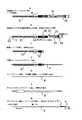
図1は本発明の第一の実施の形態を示す構成図で、Aがイントロデューサー(A−1が穿刺針突出時、A−2が穿刺針収納時)、Bがガイドワイヤー及びプロテーゼ、Cがダイレーターを示し、図2は本形態のイントロデューサーの各部で、Aが内筒外針、Bが内筒内針、Cが保護管を示している。
本例の器具は、先端に刃先12を形成した穿刺針11を接続し、基端に操作部となる内筒外針基14を接続した可撓性チューブよりなる内筒チューブ13として構成する内筒外針1と、該内筒チューブ13の内腔に挿入される、先端に刃先22を形成し、基端に内筒内針基23を接続した金属細線よりなるスタイレット21として構成する内筒内針2と、基端に操作部を含む保護管基33を接続した可撓性チューブよりなる保護チューブ31として構成する保護管3とにより、内側から内筒内針2、内筒外針1、保護管3の3重構造をとるイントロデューサーと、該イントロデューサーの保護管3内腔に挿入可能な外径で、後端部に気管食道壁に留置されるプロテーゼ5を分離可能に取り付けた可撓性のガイドワイヤー4と、前記イントロデューサーにより穿設された瘻孔を、プロテーゼ5の留置に先立ち拡張するためのダイレーター6より構成する。FIG. 1 is a configuration diagram showing a first embodiment of the present invention. A is an introducer (A-1 is when the puncture needle protrudes, A-2 is when the puncture needle is stored), B is a guide wire and prosthesis,
The instrument of this example is configured as an inner tube 13 composed of a flexible tube with a
イントロデューサーは、前記の通り3重構造となる内筒外針1、内筒内針2、保護管3、より構成されており、内筒外針1は、先端に気管食道壁を穿刺するための刃先12を形成したステンレスパイプよりなる穿刺針11と、該穿刺針と先端部で接続する比較的硬質で伸縮性の低い可撓性樹脂チューブ(例えば、フッ素樹脂チューブ)、あるいは、金属細線を網目状に編んだ金属ブレードを組み込んだ樹脂チューブより形成される内筒チューブ13と、該内筒チューブ13の基端に接続する、後記する内筒内針基23との接続部15、及び、後記する保護管基33と係合する突起16を外周面に備えた内筒外針基14により構成した。
内筒内針2は、前記内筒外針1による気管食道壁穿刺操作等で内筒チューブ13のコシの弱さを補うもので、先端に前記穿刺針11と共に気管食道壁を穿刺するための刃先22を形成したステンレス細線よりなるスタイレット21と、該スタイレット21の基端に接続する前記内筒外針基14と嵌合する内筒内針基23とにより構成した。
そして、前記内筒外針1の内腔に内筒内針2を摺動可能に挿着し、各々の基を嵌合して気管食道壁への瘻孔形成の穿刺手段となる内筒とした。尚、内筒内外針を挿着したさいスタイレット21の刃先22は穿刺針の刃先より突出させて形成されている。
保護管3は、前記内筒の穿刺針11の刃先12やスタイレット21の刃先22による意図しない接触から内視鏡の鉗子チャンネルや周辺組織を保護するため、及び、ガイドワイヤー4挿入のためのイントロデューサーとするために、前記内筒チューブ13の外套手段として該内筒チューブ13を内挿して形成するもので、先端に面取りを施した比較的硬質で伸縮性の低い可撓性樹脂チューブ(例えば、フッ素樹脂チューブ)、あるいは、金属細線を網目状に編んだ金属ブレードを組み込んだ樹脂チューブより形成される保護チューブ31と、該保護チューブ31の基端に接続する保護チューブ基33と該チューブ31を該基33と挟持して固定する接続キャップ32、及び、前記内筒外針基14と係合してスライド操作部となる筒状の外套基34とにより構成した。そして、前記外套基34の外周面には、前記内筒外針基の突起16を係合して移動可能に長手方向に形成するスリット35と、該スリット35の両端に形成する長手方向への移動を規制する固定溝36とが形成され、先端部には前記保護チューブ基32と接続するためのロックキャップ37と該チューブ基32と着脱自在に接続されるロックリング38を備えて構成した。
そして、前記内筒(内筒外針1)を保護管3の内腔に摺動可能に挿入し、保護チューブ基32とロックリング38を接続して一体としてイントロデューサーとした。
イントロデューサーのサイズは使用する内視鏡などにも左右されることから特定するものではないが、本例においては、保護チューブ31の有効長を一般的な内視鏡の鉗子孔の長さ及び操作の使用勝手を考慮して1000mm程度とし、穿刺針11の外径を前記作用が発揮される、0.5mm以上、1.6mm以下(本例においては、0.8mm)として形成し、保護チューブ31の外径を適合して1.5mm以上、2.0mm以下(本例においては、1.8mm)として形成した。また、スライド操作による穿刺針11の保護チューブ32先端からの突出長を5mm程度となるように調整した。The introducer is composed of the inner cylinder
The inner cylinder
Then, the inner cylinder
The
Then, the inner cylinder (inner cylinder outer needle 1) was slidably inserted into the lumen of the
The size of the introducer is not specified because it depends on the endoscope to be used, but in this example, the effective length of the
本形態による穿刺針11の保護管3からの突出、収納に付き詳細に説明すると、スライド操作部となる前記内筒外針基14及び外套基34は、相対的なスライド操作により内筒チューブ13が保護チューブ31内腔を摺動して、内筒チューブ13の先端の穿刺針11を保護チューブ31先端より突出、保護チューブ31内に収容できるように形成されており、内筒外針基14は先端に内筒チューブ13の後端を接着し外周面に突起16を形成してなり、外套基34はロックキャップ37、ロックリング38を介して先端に保護チューブ31の後端が接続され、内筒外針基14の外周を摺動自在に配置され、且つ、内筒外針基14の突起16が係合する長手方向に伸びたスリット35、及び周方向に伸びた針位置固定溝36からなり、スリット35内の突起16の移動範囲、つまり、スリット35の長さ分だけ内管外針基14と外套基34の相対移動が可能になっている。この相対移動に基づく穿刺針11の移動距離は穿刺針の突出長より長く設定される。また、スリット35の両端に突起が位置した状態で内筒外針基14と外套基34を相対的に回転させ、針位置固定溝36に突起16を係合させると、内筒外針基14と外套基34の長手方向の移動が規制されるようになっている。 When the
ガイドワイヤー4は、プロテーゼ5を気管食道壁に導入する導入手段となり、金属細線をらせん状に密に巻き先端を半球状に形成した公知のガイドワイヤーであって、後端部に気管食道壁の孔に留置するプロテーゼ5を着脱自在に取り付け可能な保持部41を備えて構成した。サイズは、前記外筒管13の内腔に挿入可能な外径として0.9mm、長さは、イントロデューサーより100mm程度長く設定する必要があり、本例においては1100mmとして構成する。 The
プロテーゼ5は、気管食道シャント法に従来から使用されるもので特定するものではないが、本例においては柔軟な樹脂(本例では、シリコーン樹脂)より形成され、気管食道壁を両側から挟むフランジ52を両端部に備えたボビン形状に形成される筒体のチューブで、該チューブの内腔には留置したさいに潰れを防止し形状を安定させるリング54と、気管への誤吸引を防止する逆止弁53を備え、気管側に位置する側のフランジ52に、瘻孔へ留置するさいにガイドワイヤーの保持部41に取り付けられる延長紐部51を備えて構成する。尚、延長紐部51は、留置後に切断され除去される。また、前記逆止弁53は、気管側から食道側への空気の流通は許すが、食道から気管への飲食物等は通過できない構造に形成されている。 The
ダイレーター6は、穿刺針11によって形成された瘻孔をプロテーゼ5が留置可能な大きさに拡張する拡張手段となり、前記ガイドワイヤー4を内腔に挿通することができる内径で、瘻孔が徐々に拡張できるように先端を先細り形状62に形成した比較的硬質な樹脂よりなるチューブで、基端部に把持のためのダイレーター基63を接続して構成される。サイズは、12〜18フレンチ(本例においては、15フレンチ(外径5mm))として構成した。 The
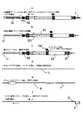
図3は、前記実施の形態を用いての気管食道壁への瘻孔の形成と、プロテーゼの留置の手順を示している。
その手順は次の通りである。
1.鼻孔または口から食道まで内視鏡を挿入し、前記内筒管13の穿刺針11が保護管3内に収納されている状態のイントロデューサーを内視鏡の鉗子チャンネル孔に挿入し(図3a)、内視鏡観察下に瘻孔形成位置となる永久気管孔に通じる部位を特定し穿刺位置近傍に保護管3先端を位置させる。
2.この状態でイントロデューサーの内筒外針基14を外套基34に対して前方にスライドさせる(内筒外針基14の突起16を外套基34のスリット35内を基側から先端側に移動させる)ことで穿刺針11を保護チューブ31より突出させ、前記特定した位置でイントロデューサー全体をスライドさせて穿刺することで、気管食道壁に瘻孔が形成される。(穿刺位置の確認は、該永久気管孔から内視鏡ファイバーの光を確認することにより観察することができる。)(図3b)ここでイントロデューサーの保護チューブ31の先端が形成された瘻孔に刺入された状態となる位置まで穿刺を進めておく。
3.穿刺後、ロックリング38を緩め保護チューブ31及び保護チューブ基32のみを残し、内筒を抜去する。(図3c)
4.残した保護チューブ31を通して鼻又は口側からガイドワイヤー4を挿入し、形成した瘻孔を通して永久気管孔からガイドワイヤーを外部に引き出す。(図3d)
5.イントロデューサーの保護チューブ31と内視鏡を同時に引き抜き、ガイドワイヤー4のみを残す。(図3e)
6.残したガイドワイヤー4をガイドとして永久気管孔側から形成された瘻孔にダイレーター6を挿入し、該瘻孔をプロテーゼ5が留置可能な径に拡張する。(図3f)
7.ガイドワイヤー4の後端にプロテーゼ5を取り付け、ガイドワイヤー4を永久気管孔側から引き抜いていくことにより引っ張られたプロテーゼ5が鼻又は口から食道を通って瘻孔に位置される。(図3g)
8.プロテーゼ5がフランジ52により気管食道壁を挟んで瘻孔に導入されたら、プロテーゼ設置用の延長紐部51を、ガイドワイヤー4の接続手段と共に切断してプロテーゼ5が瘻孔に留置される。FIG. 3 shows a procedure for forming a fistula in the tracheoesophageal wall and placing the prosthesis using the above embodiment.
The procedure is as follows.
1. An endoscope is inserted from the nostril or mouth to the esophagus, and an introducer in a state where the
2. In this state, the inner cylinder
3. After puncturing, the
4). The
5. The
6). Using the remaining
7). The
8). When the
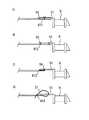
図4は、ガイドワイヤー(あるいは、後記するフレキシブルワイヤー)を永久気管孔側に引き出すことにより、プロテーゼが引っ張られ気管食道壁に誘導され留置されるさい(前記工程7)のガイドワイヤー(フレキシブルワイヤー)後端とプロテーゼの接続手段の例を示している。
ガイドワイヤー4にプロテーゼ5を着脱自在に取り付ける手段としては、図4Aのようにガイドワイヤー後端側のプロテーゼ保持部41に滑り防止のための粗し加工部411を施し、該粗し加工部411とプロテーゼの延長紐部51を糸55で巻きつけて結紮し固定する手段や、図4Bのようにプロテーゼ保持部41にサイドホール412を設け、該サイドホール412に糸55を通してプロテーゼの延長紐部51に巻き結紮して固定する手段や、図4Cのように前記プロテーゼ保持部41の端部413にループ状に形成した紐56を接続し、該紐56を2つ折にして形成される2つのリングにプロテーゼの延長紐部51を通して結び付け(前方に折り曲げ、折り曲げ先端側が外方に開いた形状をとった場合、延長紐部51を前方側から一方のリングを通し、続けて、後側から他方のリングを通すことで図のような結び目が形成される)、紐56をガイドワイヤー側に引っ張ることで該延長紐部51を締め付けて固定する手段、あるいは、図4Dのようにプロテーゼ保持部41に連続的な係合凸部を備えるバンド57の一端を接続し、一方、ガイドワイヤーに該バンド57を挿入する係止孔414を設け、該バンド57で延長紐部51を巻いて、バンド57を係止孔414に通して締め付け、該締付け位置で前記係合凸部と係止孔414を係合することで固定する手段などがあげられるが、フック状のものに引っ掛けるなどガイドワイヤーを引っ張っていくさいにプロテーゼが脱落する懸念のない取り付け容易な手段であればこれらに特定するものではない。FIG. 4 shows a guide wire (flexible wire) when the prosthesis is pulled and guided to the tracheoesophageal wall by pulling out the guide wire (or flexible wire described later) to the permanent tracheal hole side (step 7). The example of the connection means of a rear end and a prosthesis is shown.
As a means for detachably attaching the
図5は本発明の第二の実施の形態を示す構成図でAがイントロデューサー(A−1が穿刺針突出時、A−2が穿刺針収納時)、Bがフレキシブルワイヤーに接続されたプロテーゼ、Cがダイレーターを示し、図6は本形態のイントロデューサーで、Aが保護管、Bがフレキシブルワイヤーを示している。
本例の器具は、先端に刃先71を形成し、基端に気管食道壁に留置されるプロテーゼ5を分離可能に取り付けられるプロテーゼ保持部72を備えたフレキシブルワイヤー7と、該フレキシブルワイヤー7を内腔に摺動可能な可撓性樹脂よりなる保護チューブ81と、保護チューブ81の基端に備える基部(保護チューブの接続部)及び操作部からなる保護管8により構成する2重構造のイントロデューサーと、前記プロテーゼ5と、前記イントロデューサーにより穿設された瘻孔を、プロテーゼ5の留置に先立ち拡張するためのダイレーター6より構成する。FIG. 5 is a block diagram showing a second embodiment of the present invention, wherein A is an introducer (A-1 is when the puncture needle protrudes, A-2 is when the puncture needle is stored), and B is a prosthesis connected to a flexible wire. , C shows a dilator, FIG. 6 shows an introducer of this embodiment, A shows a protective tube, and B shows a flexible wire.
The instrument of this example includes a
イントロデューサーは、前記の通り2重構造となるフレキシブルワイヤー7、及び、保護管8より構成されており、フレキシブルワイヤー7は、弾性化処理を施したステンレス細線よりなり、先端に気管食道壁を穿刺するための刃先71を形成し、後端にプロテーゼ5を着脱自在に取り付けるプロテーゼ把持部72を備えて構成する。この構成により、前記実施の形態の穿刺手段となる穿刺針11を含む内筒と導入手段となるガイドワイヤー4を一体のものとすることができる。
保護管8は、前記フレキシブルワイヤー7の刃先71による意図しない接触から内視鏡の鉗子チャンネルや周辺組織を保護するため、前記フレキシブルワイヤー7の外套手段として該フレキシブルワイヤー7を内挿して形成するもので、先端に面取りを施した比較的硬質で伸縮性の低い可撓性樹脂チューブ(例えばフッ素樹脂チューブ)、あるいは、金属細線を網目状に編んだ金属ブレードを組み込んだ樹脂チューブより形成される保護チューブ81と、該保護チューブ81の基端に接続し、該チューブ81を挟持して固定する保護チューブ基82と接続キャップ83よりなる基部(保護チューブとの接続部)と、前記フレキシブルワイヤー7をスライド可能に摺動及び固定する締付けアダプター86と操作のための把持部84よりなる手元操作部と、前記基部の保護チューブ基82と操作部の把持部84を着脱自在に接続するロックリング85とにより構成した。
そして、前記フレキシブルワイヤー7を保護管8の内腔に摺動可能に挿入、締付けアダプター86を締めて固定し、保護チューブ基82とロックリング85を接続し一体としてイントロデューサーとした。
イントロデューサーのサイズは使用する内視鏡などにも左右されることから特定するものではないが、本例においては、保護チューブ81の有効長を一般的な内視鏡の鉗子孔の長さ及び操作の使用勝手を考慮して1000mmとし、フレキシブルワイヤー7の外径を前記作用が発揮される、0.5mm以上、1.6mm以下(本例においては、0.8mm)として形成し、保護チューブ81の外径を適合して1.5mm以上、2.0mm以下(本例においては、1.8mm)として形成した。また、スライド操作による穿刺針11の保護チューブ32先端からの突出長を5mm程度となるように調整した。The introducer is composed of the
The
Then, the
Although the size of the introducer depends on the endoscope used and the like, it is not specified, but in this example, the effective length of the
前記手元操作部につき詳細すると、操作部となる締付けアダプター86と把持部84の接続部となる内部接触面に柔軟な樹脂よりなる締付けリング(図示しない)を備え、リング内腔にフレキシブルワイヤー7を通し、把持部84との接続部に対して締め付けアダプター86を締め付けたり、緩めたりすることによりリング内腔の内径を拡縮させて、フレキシブルワイヤー7を特定位置に固定、あるいは、摺動可能にスライドすることができる。このスライド操作により保護管8とフレキシブルワイヤー7を相対移動して、フレキシブルワイヤー7の先端を保護チューブ81先端より突出、保護管チューブ81内に収容できるように形成さている。 More specifically, the hand operating part includes a tightening ring (not shown) made of a flexible resin on the inner contact surface serving as a connecting part between the tightening
プロテーゼ、ダイレーターは、前述した第一の実施の形態と同様なものを同様に用いれば良いため本例においては説明を省略する。また、プロテーゼ5のフレキシブルワイヤー7への取り付け手段は、前記ガイドワイヤー4への接続手段(図4参照)と同様とすれば良い。 Since the prosthesis and the dilator may be the same as those used in the first embodiment, the description thereof is omitted in this example. Further, the means for attaching the
図7は、本実施の形態を用いての気管食道壁への瘻孔の形成と、プロテーゼの留置の手順を示している。
その手順は次の通りである。
1.鼻孔または口から食道まで内視鏡を挿入し、フレキシブルワイヤー7の先端が保護管8内に収納されている状態でイントロデューサーを内視鏡の鉗子チャンネル孔に挿入し、内視鏡観察下に瘻孔形成位置となる永久気管孔に通じる部位を特定し、穿刺位置近傍に保護チューブ81先端を位置させる。(図7a)
2.操作部の締付けアダプター86を緩め、フレキシブルワイヤー7を前方に必要な長さスライドして先端を保護チューブ81より突出させ、締付けアダプター86を締め付けて固定する。この状態で、前記特定した位置でイントロデューサー全体をスライドさせて穿刺することで、気管食道壁に瘻孔が形成される。(穿刺位置の確認は、該永久気管孔から内視鏡ファイバーの光を確認することにより観察することができる。)(図7b)
3.穿刺後、締付けアダプター86を緩めフレキシブルワイヤー7のみを残し、保護管8を内視鏡と共に引き抜く。(図7c)この時点で、フレキシブルワイヤー7の先端が永久気管孔より体外に突出した位置となるまで穿刺が進められる。
4.残したフレキシブルワイヤー7をガイドとして永久気管孔側から形成された瘻孔にダイレーター6を挿入し、該瘻孔をプロテーゼ5が留置可能な径に拡張する。(図7d)
5.フレキシブルワイヤー7の後端にプロテーゼ5を取り付け、フレキシブルワイヤー7を永久気管孔から引き抜いていくことにより引っ張られたプロテーゼ5が鼻又は口から食道を通って瘻孔に位置される。(図7e)
6.プロテーゼ5がフランジ52により気管食道壁を挟んで瘻孔に導入されたら、プロテーゼ設置用の延長紐部51を、フレキシブルワイヤー7の接続手段と共に切断してプロテーゼ5が瘻孔に留置される。FIG. 7 shows a procedure for forming a fistula in the tracheoesophageal wall and placing the prosthesis using the present embodiment.
The procedure is as follows.
1. An endoscope is inserted from the nostril or mouth to the esophagus, and an introducer is inserted into the forceps channel hole of the endoscope while the tip of the
2. The tightening
3. After puncturing, the tightening
4). The
5. The
6). When the
図8は本発明の第三の実施の形態を示す構成図でAがイントロデューサー(A−1が穿刺針突出時、A−2が穿刺針収納時)、Bがフレキシブルワイヤーに接続されたプロテーゼ、Cがダイレーターを示し、図9は本形態のイントロデューサーで、Aが保護管、Bがフレキシブルワイヤーを示している。
本例の器具は、イントロデューサーを内視鏡の鉗子チャンネルに固定して使用する形態の器具で、先端に刃先71を形成し、基端に気管食道壁に留置されるプロテーゼ5を分離可能に取り付けられるプロテーゼ保持部72を備えた前記第二の形態と同様のフレキシブルワイヤー7と、該フレキシブルワイヤー7を内腔に摺動可能な可撓性樹脂よりなる保護チューブ91、保護チューブ91の基端に備える基部(保護チューブの接続部)、内視鏡の鉗子チャンネルからの保護チューブ91先端の出長さを調整するスライド部、保護チューブ91からのフレキシブルワイヤー7の先端の出長さを調整するスライド部を備えた操作部、及び内視鏡の鉗子チャンネルに着脱自在に取り付けられる内視鏡接続リング96とからなる保護管9より構成する2重構造のイントロデューサーと、前記プロテーゼ5、及び、前記イントロデューサーにより穿設された瘻孔を、プロテーゼ5の留置に先立ち拡張するためのダイレーター6より構成する。FIG. 8 is a block diagram showing a third embodiment of the present invention, wherein A is an introducer (A-1 is when the puncture needle protrudes, A-2 is when the puncture needle is stored), and B is a prosthesis connected to a flexible wire. , C shows a dilator, FIG. 9 shows an introducer of this embodiment, A shows a protective tube, and B shows a flexible wire.
The instrument of this example is an instrument in which the introducer is used while being fixed to the forceps channel of the endoscope, and the
イントロデューサーは、前記の通り2重構造となるフレキシブルワイヤー7、及び、保護管9より構成されており、フレキシブルワイヤー7は、前記第二の実施の形態と同様のものを同様に用いれば良いため本例においては説明を省略する。
保護管9は、前記フレキシブルワイヤー7の刃先71による意図しない接触から内視鏡の鉗子チャンネルや周辺組織を保護するため、前記フレキシブルワイヤー7の外套手段として該フレキシブルワイヤー7を内挿して形成するもので、先端に面取りを施した比較的硬質で伸縮性の低い可撓性樹脂チューブ(例えばフッ素樹脂チューブ)、あるいは、金属細線を網目状に編んだ金属ブレードを組み込んだ樹脂チューブより形成される保護チューブ91と、該保護チューブ91の基端に接続しチューブを固定する、後記する内視鏡出長さ調整スライドともなる保護チューブ基93と、イントロデューサーを内視鏡の鉗子チャンネルに固定するさいに、鉗子チャンネル先端からの保護チューブ91の出長さを調整する前記保護チューブ基ともなる内視鏡出長さ調整スライド93及び該内視鏡出長さ調整スライド93の相対的なスライド部となる出長さ調整スライドバー92と、前記保護チューブ91からのフレキシブルワイヤー7の出長さを調整する穿刺長調整スライド94と、前記フレキシブルワイヤー7をリングの締付けにより固定する締付けアダプター95と、内視鏡の鉗子チャンネルへの接続部となる内視鏡接続リング96とにより構成した。
そして、前記フレキシブルワイヤー7を保護管9の内腔に摺動可能に挿入し、保護管9の穿刺長調整スライド94の後端部に締付けアダプター95で締め付けて接続し一体としてイントロデューサーとした。
イントロデューサーのサイズは使用する内視鏡などにも左右されることから特定するものではないが、本例においては、保護チューブ91の有効長を一般的な内視鏡の鉗子孔の長さ及び操作の使用勝手を考慮して1000mmとし、フレキシブルワイヤー7の外径を前記作用が発揮される、0.5mm以上、1.6mm以下(本例においては、0.8mm)として形成し、保護チューブ91の外径を適合して1.5mm以上、2.0mm以下(本例においては、1.8mm)として形成した。また、スライド操作による穿刺針11の保護チューブ32先端からの突出長を5mmとなるように調整した。The introducer is composed of the
The
The
Although the size of the introducer depends on the endoscope used, etc., it is not specified, but in this example, the effective length of the
保護管9の基部に付き詳細に説明すると、前記の通り保護チューブ91の後端との接続部となる保護チューブ基93は、鉗子チャンネル先端からの保護チューブ91の出長さを調整する内視鏡出長さ調整スライド93ともなっており、該内視鏡出長さ調整スライド93は、相対的なスライド部となる先端部に把持部921と内視鏡接続リング96との接続部を備える出長さ調整スライドバー92を内接し、摺動して軸方向前後にスライドすることにより前記鉗子チャンネル先端からの保護チューブ91先端の突出する長さを調整することができ、また、該内視鏡出長さ調整スライド93の外周面に設ける出長さ調整ストッパー931を締め付けることで、内視鏡出長さ調整スライド93と出長さ調整スライドバー92を所望の位置で固定することができる。
また、この内視鏡出長さ調整スライド93は、前記保護チューブ91からのフレキシブルワイヤー7の出長さを調整する穿刺長調整スライド94を外接しており、前記出長さ調整スライドバー92と内視鏡出長さ調整スライド93との関係と同様に、穿刺長調整スライド94を内視鏡出長さ調整スライド93に摺動させ軸方向前後にスライドすることにより、前記保護チューブ91先端からのフレキシブルワイヤー7先端の突出の長さを調整することができ、また、穿刺長調整スライド94の外周面に設ける穿刺スライド調整ストッパー941を締め付けることで、内視鏡出長さ調整スライド93と穿刺長調整スライド94を所望の位置で固定することができる。尚、本例においては、内視鏡出長さ調整スライド93にメモリ932(本例においては、0mm〜60mm)設けられておりスライド長さを確認しての操作ができる。
フレキシブルワイヤー7の固定部となる締付けアダプター95は、接続部となる穿刺長調整スライド94の後端部との内部接触面に柔軟な樹脂よりなる締付けリング(図示しない)が備えられ、リング内腔にフレキシブルワイヤー7を通し、締め付けたり、緩めたりすることによりリング内腔の内径を拡縮させて、フレキシブルワイヤー7を着脱自在に特定位置に固定することができる。
内視鏡の鉗子チャンネルへの接続部となる内視鏡接続リング96は、保護管9基部の最先端に位置し、出長さ調整スライドバー92の先端部に接続して設けられ内視鏡の鉗子チャンネルの入口の接続手段と累合して固定される。Describing in detail with respect to the base portion of the
The endoscope extension
The tightening
An
プロテーゼ、ダイレーターは、前述した第一の実施の形態と同様なものを同様に用いれば良いため本例においては説明を省略する。また、プロテーゼ5のフレキシブルワイヤー7への取り付け手段は、前記ガイドワイヤー4への接続手段(図4参照)と同様とすれば良い。 Since the prosthesis and the dilator may be the same as those used in the first embodiment, the description thereof is omitted in this example. Further, the means for attaching the
図10は、本実施の形態を用いての気管食道壁への瘻孔の形成と、プロテーゼの留置の手順を示している。
その手順は次の通りである。
1.鼻孔または口から食道まで内視鏡を挿入し、フレキシブルワイヤー7の先端が保護チューブ91内に収納されている状態でイントロデューサーを内視鏡の鉗子チャンネル孔に挿入し、内視鏡観察下に瘻孔形成位置となる永久気管孔に通じる部位を特定して、該特定した位置でイントロデューサーを内視鏡接続リング96により内視鏡チャンネルに固定する。(図10a)
2.出長さ調整ストッパー931を緩め内視鏡出長さ調整スライド93を前進させ、保護チューブ91の鉗子チャンネルからの出長さを調整し、穿刺位置近傍に保護チューブ91先端を位置させ出長さ調整ストッパー931を締め固定する。(図10b)
3.穿刺スライド調整ストッパー941を緩め穿刺長調整スライド94を前進させることで、フレキシブルワイヤー7が気管食道壁に穿刺され瘻孔が形成される。(穿刺位置の確認は、該永久気管孔から内視鏡ファイバーの光を確認することにより観察することができる。)(図10c)
4.穿刺後、締付けアダプター95、及び、内視鏡接続リング96を緩めフレキシブルワイヤー7のみを残し、保護管9を内視鏡と共に引き抜く。(図10d)
5.残したフレキシブルワイヤー7をガイドとして永久気管孔から形成された瘻孔にダイレーター6を挿入し、該瘻孔をプロテーゼ5が留置可能な径に拡張する。(図10e)
6.フレキシブルワイヤー7の後端にプロテーゼ5を取り付け、フレキシブルワイヤー7を永久気管孔から引き抜いていくことにより引っ張られたプロテーゼ5が鼻又は口から食道を通って瘻孔に位置される。(図10f)
7.プロテーゼ5がフランジ52により気管食道壁を挟んで瘻孔に導入されたら、プロテーゼ設置用の延長紐部51を、フレキシブルワイヤー7の接続手段と共に切断してプロテーゼ5が瘻孔に留置される。FIG. 10 shows a procedure for forming a fistula in the tracheoesophageal wall and placing the prosthesis using the present embodiment.
The procedure is as follows.
1. The endoscope is inserted from the nostril or mouth to the esophagus, and the introducer is inserted into the forceps channel hole of the endoscope with the distal end of the
2. The projection
3. When the puncture
4). After puncturing, the tightening
5. The
6). The
7). When the
1. 内筒外針
11. 穿刺針
12. 刃先
13. 内筒管
14. 内筒外針基
16. 突起
2. 内筒内針
21. スタイレット
22. 刃先
23. 内筒内針基
3. 保護管
31. 保護チューブ
32. 保護チューブ基
34. 外套基
35. スリット
36. 針位置固定溝
38. ロックリング
4. ガイドワイヤー
41. プロテーゼ保持部
411.粗し加工部
412.サイドホール
413.紐取り付け部
414.係止孔
5. プロテーゼ
51. 延長紐部
52. フランジ
53. 逆止弁
54. リング
55. 結紮糸
56. 固定紐
57. バンド
6. ダイレーター
61. 先細り部
62. ダイレーター基
7. フレキシブルワイヤー
71. 刃先
8. 保護管
81. 保護チューブ
82. 保護チューブ基
84. 把持部
85. ロックリング
86. 締付けリング
9. 保護管
91. 保護チューブ
92. 出長さ調整スライドバー
93. 内視鏡出長さ調整スライド
931.出長さ調整ストッパー
94. 穿刺長調整スライド
941.穿刺スライド調整ストッパー
95. 締付けアダプター
96. 内視鏡接続リング1. Inner cylinder
Claims (8)
Translated fromJapanesePriority Applications (1)
| Application Number | Priority Date | Filing Date | Title |
|---|---|---|---|
| JP2011029478AJP5616250B2 (en) | 2011-02-15 | 2011-02-15 | Tracheoesophageal prosthesis indwelling device |
Applications Claiming Priority (1)
| Application Number | Priority Date | Filing Date | Title |
|---|---|---|---|
| JP2011029478AJP5616250B2 (en) | 2011-02-15 | 2011-02-15 | Tracheoesophageal prosthesis indwelling device |
Publications (2)
| Publication Number | Publication Date |
|---|---|
| JP2012165895Atrue JP2012165895A (en) | 2012-09-06 |
| JP5616250B2 JP5616250B2 (en) | 2014-10-29 |
Family
ID=46970681
Family Applications (1)
| Application Number | Title | Priority Date | Filing Date |
|---|---|---|---|
| JP2011029478AActiveJP5616250B2 (en) | 2011-02-15 | 2011-02-15 | Tracheoesophageal prosthesis indwelling device |
Country Status (1)
| Country | Link |
|---|---|
| JP (1) | JP5616250B2 (en) |
Cited By (3)
| Publication number | Priority date | Publication date | Assignee | Title |
|---|---|---|---|---|
| JP2019500081A (en)* | 2015-12-02 | 2019-01-10 | アトス メディカル アクティエボラーグ | Device for securely mounting and attaching a tubular device to a flexible wall |
| CN112546338A (en)* | 2019-09-26 | 2021-03-26 | 梅州市人民医院 | Catheter |
| IT202300006159A1 (en)* | 2023-03-30 | 2024-09-30 | Gm S R L | SYSTEM FOR THE CREATION OF A TRACHEO-ESOPHAGEAL FISTULA AND CONSEQUENT INSERTION OF THE TALKING VALVE UNDER LOCAL ANAESTHESIA |
Citations (4)
| Publication number | Priority date | Publication date | Assignee | Title |
|---|---|---|---|---|
| US5078743A (en)* | 1990-04-19 | 1992-01-07 | Abraham Mikalov | Method of placing an esophageal voice prosthesis in a laryngectomized person |
| US6159243A (en)* | 1996-05-06 | 2000-12-12 | Schouwenburg; Paul Ferdinand | Kit for implantation of a voice prosthesis in patients on whom a laryngectomy has been performed |
| US6776797B1 (en)* | 1992-01-10 | 2004-08-17 | Hansa Medical Products, Inc. | Method of inserting a flanged device into a human body |
| JP4122058B2 (en)* | 1995-12-22 | 2008-07-23 | アトス メディカル アクティエボラーグ | Method and apparatus for attaching a tubular device to a flexible wall |
- 2011
- 2011-02-15JPJP2011029478Apatent/JP5616250B2/enactiveActive
Patent Citations (4)
| Publication number | Priority date | Publication date | Assignee | Title |
|---|---|---|---|---|
| US5078743A (en)* | 1990-04-19 | 1992-01-07 | Abraham Mikalov | Method of placing an esophageal voice prosthesis in a laryngectomized person |
| US6776797B1 (en)* | 1992-01-10 | 2004-08-17 | Hansa Medical Products, Inc. | Method of inserting a flanged device into a human body |
| JP4122058B2 (en)* | 1995-12-22 | 2008-07-23 | アトス メディカル アクティエボラーグ | Method and apparatus for attaching a tubular device to a flexible wall |
| US6159243A (en)* | 1996-05-06 | 2000-12-12 | Schouwenburg; Paul Ferdinand | Kit for implantation of a voice prosthesis in patients on whom a laryngectomy has been performed |
Cited By (3)
| Publication number | Priority date | Publication date | Assignee | Title |
|---|---|---|---|---|
| JP2019500081A (en)* | 2015-12-02 | 2019-01-10 | アトス メディカル アクティエボラーグ | Device for securely mounting and attaching a tubular device to a flexible wall |
| CN112546338A (en)* | 2019-09-26 | 2021-03-26 | 梅州市人民医院 | Catheter |
| IT202300006159A1 (en)* | 2023-03-30 | 2024-09-30 | Gm S R L | SYSTEM FOR THE CREATION OF A TRACHEO-ESOPHAGEAL FISTULA AND CONSEQUENT INSERTION OF THE TALKING VALVE UNDER LOCAL ANAESTHESIA |
Also Published As
| Publication number | Publication date |
|---|---|
| JP5616250B2 (en) | 2014-10-29 |
Similar Documents
| Publication | Publication Date | Title |
|---|---|---|
| US6706017B1 (en) | Percutaneous ostomy device and method for creating a stoma and implanting a canula | |
| JP2013027704A (en) | Loading dilator | |
| CN102448531B (en) | Introducer guide | |
| EP3614898B1 (en) | Instrument for accessing and visualizing hollow organs | |
| EP2704782B1 (en) | Dilatation system for a medical device | |
| JPWO2003103566A1 (en) | Gastrostomy construction method, contamination prevention cover used in gastrostomy construction, contamination prevention catheter kit, and gastrostomy catheter | |
| JP5616250B2 (en) | Tracheoesophageal prosthesis indwelling device | |
| US8997748B2 (en) | Dilator assembly, a device for facilitating tracheostomy and methods of making a percutaneous tracheostoma | |
| WO2007057127A1 (en) | Expandable device for insertion into organ and/or body orifices | |
| CN102018549B (en) | Percutaneous tracheotomy device | |
| WO2015078114A1 (en) | Staged-extension percutaneous tracheotomy device | |
| US20140228952A1 (en) | Dilator for inserting a voice prosthesis | |
| JP5632224B2 (en) | Gastrostomy dilator | |
| CN202637044U (en) | A minimally invasive percutaneous tracheostomy | |
| CN203494044U (en) | A kind of percutaneous tracheal dilator with sheath | |
| CA3217617A1 (en) | Endotracheal tube support devices | |
| CN101953701B (en) | Percutaneous tracheotomy device | |
| CN201905970U (en) | A percutaneous tracheostomy | |
| EP2874687B1 (en) | Device for emergency apneic oxygenation | |
| IT202000017461A1 (en) | COMPONENT KIT FOR PERCUTANEOUS EXTRUSION DILATED TRACHEOSTOMY | |
| CN201939442U (en) | A percutaneous tracheostomy | |
| WO2006087032A1 (en) | Dilatative percutaneous tracheotomy device | |
| CN202619803U (en) | A blade type percutaneous tracheotomy device | |
| WO2014078035A1 (en) | Nasal trumpet | |
| US20230053208A1 (en) | Nasal Right Angle Endotracheal (RAE) Tube Protective Tip and Method of Use |
Legal Events
| Date | Code | Title | Description |
|---|---|---|---|
| A621 | Written request for application examination | Free format text:JAPANESE INTERMEDIATE CODE: A621 Effective date:20140108 | |
| A871 | Explanation of circumstances concerning accelerated examination | Free format text:JAPANESE INTERMEDIATE CODE: A871 Effective date:20140507 | |
| A975 | Report on accelerated examination | Free format text:JAPANESE INTERMEDIATE CODE: A971005 Effective date:20140522 | |
| A131 | Notification of reasons for refusal | Free format text:JAPANESE INTERMEDIATE CODE: A131 Effective date:20140717 | |
| A521 | Request for written amendment filed | Free format text:JAPANESE INTERMEDIATE CODE: A523 Effective date:20140804 | |
| TRDD | Decision of grant or rejection written | ||
| A01 | Written decision to grant a patent or to grant a registration (utility model) | Free format text:JAPANESE INTERMEDIATE CODE: A01 Effective date:20140904 | |
| A61 | First payment of annual fees (during grant procedure) | Free format text:JAPANESE INTERMEDIATE CODE: A61 Effective date:20140911 | |
| R150 | Certificate of patent or registration of utility model | Ref document number:5616250 Country of ref document:JP Free format text:JAPANESE INTERMEDIATE CODE: R150 |