JP2012165864A - Golf club and method for adjusting characteristic of the same - Google Patents
Golf club and method for adjusting characteristic of the sameDownload PDFInfo
- Publication number
- JP2012165864A JP2012165864AJP2011028744AJP2011028744AJP2012165864AJP 2012165864 AJP2012165864 AJP 2012165864AJP 2011028744 AJP2011028744 AJP 2011028744AJP 2011028744 AJP2011028744 AJP 2011028744AJP 2012165864 AJP2012165864 AJP 2012165864A
- Authority
- JP
- Japan
- Prior art keywords
- shaft
- golf club
- shaft case
- case
- spacer
- Prior art date
- Legal status (The legal status is an assumption and is not a legal conclusion. Google has not performed a legal analysis and makes no representation as to the accuracy of the status listed.)
- Pending
Links
Images


Classifications
- A—HUMAN NECESSITIES
- A63—SPORTS; GAMES; AMUSEMENTS
- A63B—APPARATUS FOR PHYSICAL TRAINING, GYMNASTICS, SWIMMING, CLIMBING, OR FENCING; BALL GAMES; TRAINING EQUIPMENT
- A63B53/00—Golf clubs
- A63B53/02—Joint structures between the head and the shaft
- A—HUMAN NECESSITIES
- A63—SPORTS; GAMES; AMUSEMENTS
- A63B—APPARATUS FOR PHYSICAL TRAINING, GYMNASTICS, SWIMMING, CLIMBING, OR FENCING; BALL GAMES; TRAINING EQUIPMENT
- A63B60/00—Details or accessories of golf clubs, bats, rackets or the like
- A63B60/54—Details or accessories of golf clubs, bats, rackets or the like with means for damping vibrations
- A—HUMAN NECESSITIES
- A63—SPORTS; GAMES; AMUSEMENTS
- A63B—APPARATUS FOR PHYSICAL TRAINING, GYMNASTICS, SWIMMING, CLIMBING, OR FENCING; BALL GAMES; TRAINING EQUIPMENT
- A63B2209/00—Characteristics of used materials
- A63B2209/10—Characteristics of used materials with adhesive type surfaces, i.e. hook and loop-type fastener
- A—HUMAN NECESSITIES
- A63—SPORTS; GAMES; AMUSEMENTS
- A63B—APPARATUS FOR PHYSICAL TRAINING, GYMNASTICS, SWIMMING, CLIMBING, OR FENCING; BALL GAMES; TRAINING EQUIPMENT
- A63B53/00—Golf clubs
- A63B53/02—Joint structures between the head and the shaft
- A63B53/022—Joint structures between the head and the shaft allowing adjustable positioning of the head with respect to the shaft
- A63B53/023—Joint structures between the head and the shaft allowing adjustable positioning of the head with respect to the shaft adjustable angular orientation
Landscapes
- Health & Medical Sciences (AREA)
- General Health & Medical Sciences (AREA)
- Physical Education & Sports Medicine (AREA)
- Golf Clubs (AREA)
Abstract
Translated fromJapaneseDescription
Translated fromJapanese本発明は、ゴルフクラブに係り、特にライ角、スライス角、プログレッション等の特性の調節を容易に行うことができるゴルフクラブに関する。また、本発明は、このゴルフクラブの特性調節方法に関する。 The present invention relates to a golf club, and more particularly to a golf club capable of easily adjusting characteristics such as a lie angle, a slice angle, and a progression. The present invention also relates to a method for adjusting the characteristics of the golf club.
ゴルフクラブは、シャフトの先端部にヘッドが取り付けられたものである。シャフトの基端側にグリップが装着されている。 A golf club has a head attached to the tip of a shaft. A grip is attached to the proximal end of the shaft.
従来の一般的なゴルフクラブヘッドにあっては、ヘッドに直にホゼル穴が設けられており、シャフトは該ホゼル穴に挿入され、接着剤によって固着されている。なお、この接着剤は、一般にエポキシ系接着剤が用いられている。シャフト交換に際しては、ホゼル部分を加熱してエポキシ樹脂硬化物よりなる組織を壊すことにより、シャフトを引き抜くことができる。 In a conventional general golf club head, a hosel hole is provided directly in the head, and a shaft is inserted into the hosel hole and fixed by an adhesive. In general, an epoxy adhesive is used as the adhesive. When exchanging the shaft, the shaft can be pulled out by heating the hosel part to break the structure made of the cured epoxy resin.
このような従来の一般的なゴルフクラブヘッドでは、シャフトの交換に手間がかかる。また、ライ角、スライス角、プログレッション等の特性調節はできない。 In such a conventional general golf club head, it takes time to replace the shaft. In addition, characteristics such as lie angle, slice angle, and progression cannot be adjusted.
特許文献1には、シャフトの交換が容易であると共に、ライ角やスライス角、プログレッション等の特性を調節することができるゴルフクラブと、その特性調節方法が記載されている。この特許文献1のゴルフクラブのヘッドは、シャフトの先端を取り付けるためのホゼル挿入穴を備えたゴルフクラブヘッドにおいて、該ホゼル挿入穴の入口部内周面に形成された雌螺子と、シャフトケース挿入穴を有し、該ホゼル挿入穴の奥部に着脱可能に装着されたホゼルと、シャフト挿入穴を有し、先端側が該シャフトケース挿入穴に着脱可能に装着されたシャフトケースと、該シャフトケースに外嵌した、軸心線方向移動不能なリングホルダと、該リングホルダに周方向に回転自在に外嵌した、軸心線方向移動不能な螺子部材とを備え、該螺子部材の外周面に設けられた雄螺子が前記雌螺子に螺合しているものである。
特許文献1のゴルフクラブにあっては、螺子部材をホゼル挿入穴入口部の雌螺子に着脱することによりシャフトケースを固定したりホゼル装着穴から抜き出すことができる。そこで、このホゼル及びリングホルダをライ角、スライス角又はプログレッションの異なる別のホゼル及びリングホルダに交換するか又はホゼルの周方向位相を変更し、このホゼルを介してシャフト付きシャフトケースを再びヘッド本体に装着する。 In the golf club of
例えば、シャフトの軸心がホゼル挿入穴の軸心に対し斜め方向(例えば斜交方向)となるホゼル及びリングホルダに交換することにより、ヘッド本体に対するシャフトの取り付け方向が変更され、ライ角やスライス角が変更される。 For example, by replacing the shaft with the hosel and ring holder whose shaft center is oblique to the shaft center of the hosel insertion hole (for example, the oblique direction), the mounting direction of the shaft relative to the head body is changed, and the lie angle and slice The corner is changed.
従って、全く同一のシャフト及び同一のヘッド本体からなるゴルフクラブにおいて、ライ角又はスライス角のみを調節することができる。 Therefore, in a golf club consisting of exactly the same shaft and the same head body, only the lie angle or slice angle can be adjusted.
また、シャフトケース挿入穴の軸心位置がホゼル挿入穴の軸心位置から平行移動状にずれているホゼル及びリングホルダに交換することにより、全く同一のシャフト及び同一のヘッド本体からなるゴルフクラブにおいて、プログレッションや、シャフトから重心までの距離(重心距離)を調節することができる。 In addition, in a golf club consisting of the same shaft and the same head body by exchanging with a hosel and a ring holder in which the axial center position of the shaft case insertion hole is shifted in parallel movement from the axial position of the hosel insertion hole. Progression and the distance from the shaft to the center of gravity (center of gravity distance) can be adjusted.
さらに、特許文献1では、ホゼル及びリングホルダを交換せずにシャフトケース付きシャフトを交換してシャフト交換することもできる。即ち、シャフトケースとして全く同型のシャフトケースを用意しておき、このシャフトケースに別特性のシャフトを固着してシャフトケース・シャフト連結体としておき、このシャフトケース・シャフト連結体をそれまでのヘッドシャフトケース・シャフト連結体と交換して当該ヘッドのホゼルに取り付けることにより、シャフトのみが異なったゴルフクラブを得ることができる。 Furthermore, in
上記特許文献1のゴルフクラブでは、シャフトケースに外嵌したリングホルダと、該リングホルダに外嵌した螺子部材とが必要であり、部材コストが若干高い。本発明は、シャフトの交換が容易であると共に、ライ角やスライス角、プログレッション等の特性を調節することができ、しかも、特許文献1よりも製作コストが低いゴルフクラブと、その特性調節方法を提供することを目的とする。 The golf club of
請求項1のゴルフクラブは、シャフトの先端にヘッドが取り付けられたゴルフクラブにおいて、該シャフトの先端に略筒形のシャフトケースが固着され、前記ヘッドのホゼルの筒部内に該シャフトケースが挿入され、該筒部の下部に仕切板部が設けられ、該シャフトケースの先端と該仕切板部との間にスペーサが介在されており、該シャフトケースが該スペーサに回転不能に係合しており、該スペーサ及び該仕切板部には、該スペーサの回転を阻止するためのストッパ部が設けられており、該仕切板部及びスペーサに設けられたボルト挿通孔に対し該ヘッドのソール側から差し込まれたボルトが該シャフトケースにねじ込まれ、これによりシャフトケースが該ヘッドに固定されていることを特徴とするものである。 The golf club according to
請求項2のゴルフクラブは、請求項1において、前記シャフトの軸心が前記筒部の軸心と同軸状となっていることを特徴とするものである。 According to a second aspect of the present invention, the golf club according to the first aspect is characterized in that the axis of the shaft is coaxial with the axis of the cylindrical portion.
請求項3のゴルフクラブは、請求項1において、前記シャフトの軸心が前記筒部の軸心に対し傾斜方向となっていることを特徴とするものである。 According to a third aspect of the present invention, the golf club according to the first aspect is characterized in that the shaft center of the shaft is inclined with respect to the shaft center of the cylindrical portion.
請求項4のゴルフクラブは、請求項1において、前記シャフトの軸心と前記筒部の軸心とが平行であることを特徴とするものである。 According to a fourth aspect of the present invention, the golf club according to the first aspect is characterized in that the axis of the shaft and the axis of the cylindrical portion are parallel to each other.
請求項5のゴルフクラブは、請求項1ないし4のいずれか1項において、前記スペーサにシャフトケース挿入穴が設けられており、前記シャフトケースの下端側及びシャフトケース挿入穴が多角断面形状となっており、両者が係合していることを特徴とするものである。 A golf club according to a fifth aspect is the golf club according to any one of the first to fourth aspects, wherein the spacer is provided with a shaft case insertion hole, and the lower end side of the shaft case and the shaft case insertion hole have a polygonal cross-sectional shape. The two are engaged with each other.
請求項6のゴルフクラブの特性調節方法は、請求項1ないし5のいずれか1項に記載のゴルフクラブの特性を調節する方法であって、前記ボルトを外して前記スペーサからシャフトケースを離反させ、該シャフトケースを回転させてシャフト挿入穴の位置又はシャフトの傾きを変更した後、再度該シャフトケースをスペーサと係合させ、前記ボルトによって固定することを特徴とするものである。 A method for adjusting the characteristics of a golf club according to
請求項7のゴルフクラブの特性調節方法は、請求項1ないし5のいずれか1項に記載のゴルフクラブのシャフトを新たなシャフトに交換して特性を調節する方法であって、予め新たなシャフトを新たなシャフトケースに固着して新たなシャフトケース・シャフト連結体を作成しておき、ゴルフクラブに取り付けられているシャフトケース・シャフト連結体をヘッドから取り外し、このヘッドに新たなシャフトケース・シャフト連結体を取り付けることを特徴とするものである。 A method for adjusting characteristics of a golf club according to
本発明のゴルフクラブでは、シャフトケースがホゼルの筒部に挿入され、ソール側から差し込まれたボルトによって該シャフトケースを固定しているので、前記特許文献1のリングホルダや、環状螺子部材が不要であり、低コストである。 In the golf club of the present invention, the shaft case is inserted into the cylindrical portion of the hosel, and the shaft case is fixed by a bolt inserted from the sole side. Therefore, the ring holder and the annular screw member of
本発明のゴルフクラブにあっては、このホゼル穴の底部とシャフトケース先端部との間にスペーサが介在されており、このスペーサの回転がストッパ部によって阻止されている。また、このシャフトケースの先端部とスペーサとが回転不能に係合しているので、シャフトケースの周方向の位置決めがなされる。 In the golf club of the present invention, a spacer is interposed between the bottom portion of the hosel hole and the tip end portion of the shaft case, and the rotation of the spacer is prevented by the stopper portion. Moreover, since the front-end | tip part of this shaft case and the spacer are engaged so that rotation is impossible, positioning of the shaft case in the circumferential direction is made.
本発明のシャフト交換方法にあっては、ボルトを緩めて外すと、シャフトケースをホゼルの筒部から抜き出すことができる。従って、例えば、シャフトの軸心がシャフトケース挿入穴の軸心に対し斜め方向(例えば斜交方向)となっているシャフトケースを用いた場合には、シャフトケースの周方向位相を変更することにより、ヘッド本体に対するシャフトの取り付け方向が変更され、ライ角やスライス角が変更される。 In the shaft replacement method of the present invention, the shaft case can be extracted from the cylindrical portion of the hosel by loosening and removing the bolts. Therefore, for example, when using a shaft case in which the shaft center is in an oblique direction (for example, an oblique direction) with respect to the shaft case insertion hole, by changing the circumferential phase of the shaft case The shaft mounting direction with respect to the head body is changed, and the lie angle and slice angle are changed.
従って、シャフトの軸心がシャフトケース挿入穴の軸心に対し斜め方向(例えば斜交方向)となっているシャフトケースを用いた場合には、シャフトケースの周方向位相を変更することにより、ヘッド本体に対するシャフトの取り付け方向が変更され、ライ角やスライス角が変更される。 Therefore, when using a shaft case in which the shaft center is in an oblique direction (for example, oblique direction) with respect to the shaft case insertion hole axis, the head phase is changed by changing the circumferential phase of the shaft case. The direction in which the shaft is attached to the main body is changed, and the lie angle and slice angle are changed.
これにより、全く同一のシャフト及び同一のヘッド本体からなるゴルフクラブにおいて、ライ角又はスライス角のみを調節することができる。 Thereby, in the golf club which consists of the completely same shaft and the same head main body, only a lie angle or a slice angle can be adjusted.
また、シャフトケース挿入穴の軸心位置がホゼル挿入穴の軸心位置から平行移動状にずれた形状となっているシャフトケースを用いた場合には、シャフトケースの周方向位相を変更することにより、全く同一のシャフト及び同一のヘッド本体からなるゴルフクラブにおいて、プログレッションや、シャフトから重心までの距離(重心距離)を調節することができる。 In addition, when using a shaft case in which the shaft center position of the shaft case insertion hole is shifted parallel to the axis position of the hosel insertion hole, the circumferential direction phase of the shaft case is changed. In a golf club composed of exactly the same shaft and the same head body, the progression and the distance from the shaft to the center of gravity (center of gravity distance) can be adjusted.
本発明では、シャフトケースとして全く同型のシャフトケースを用意しておき、このシャフトケースに別特性のシャフトを固着してシャフトケース・シャフト連結体としておき、このシャフトケース・シャフト連結体をそれまでのヘッドのシャフトケース・シャフト連結体と交換して当該ヘッドのホゼルに取り付けることにより、シャフトが異なったゴルフクラブを得ることができる。 In the present invention, a shaft case of exactly the same type is prepared as a shaft case, and a shaft with a different characteristic is fixed to the shaft case as a shaft case / shaft coupling body. A golf club with a different shaft can be obtained by replacing the head case with the shaft case / shaft assembly and attaching it to the hosel of the head.
このように、本発明によれば、従来のように加熱によって接着剤の組織を壊してシャフトを取り外し、新たなシャフトを再度接着剤で取り付けるという面倒な手間及び時間を省くことができる。そのため、試打したばかりのゴルフクラブのヘッドからシャフトケース・シャフト連結体を取り外し、このヘッドに異なる特性の別のシャフトケース・シャフト連結体を取り付けて直ちに試打を行うことができるので、ゴルフショップ等でゴルファーが適切なゴルフクラブを見出すことが極めて容易となる。また、ヘッドの固体差を考慮することなくシャフトの評価を行うことができる。 As described above, according to the present invention, it is possible to save the troublesome labor and time of breaking the tissue of the adhesive by heating, removing the shaft, and attaching a new shaft again with the adhesive as in the prior art. Therefore, it is possible to remove the shaft case / shaft coupling body from the head of the golf club that has just been tried and attach another shaft case / shaft coupling body with different characteristics to this head, so that the test can be performed immediately. It becomes extremely easy for the golfer to find a suitable golf club. Further, the shaft can be evaluated without considering the difference between the individual heads.
近年、ゴルファーが自分の技量にあったゴルフクラブを探すために、コンピュータや高速カメラなどを使って、自分にマッチしたゴルフクラブを探すシステムが開発されてきている。このようなシステムは、ヘッドスピードや打ち出し角度などを基に個々の市販クラブをベースに打ち比べて探すようにしたシステムである。 In recent years, a system for searching for a golf club that matches a golf club using a computer or a high-speed camera has been developed in order for a golfer to search for a golf club suitable for his / her skill. Such a system is a system in which a search is made by comparing individual commercial clubs based on the head speed, launch angle, and the like.
これに対し、本発明のゴルフクラブによれば、同一のシャフトとヘッドとの位置関係のみを変更して重心距離やプログレッションを変更し、打ち出されたボールの飛球特性(打ち出し角やスピン)の違いを容易に実感したり、同じヘッドに対してシャフトのみを付け替えて、シャフトのみの違いを実感したりすることができる。また、その日のプレーヤーの調子に応じてシャフトを交換したり、シャフトは同一のまま、ライ角やスライス角、プログレッションを調整することもできる。 On the other hand, according to the golf club of the present invention, only the positional relationship between the same shaft and the head is changed to change the center-of-gravity distance and progression, and the flying ball characteristics (launch angle and spin) of the launched ball are changed. You can easily feel the difference, or change only the shaft to the same head and feel the difference only in the shaft. Also, the shaft can be exchanged according to the player's condition of the day, or the lie angle, slice angle, and progression can be adjusted while the shaft remains the same.
以下、図面を参照して実施の形態について説明する。 Hereinafter, embodiments will be described with reference to the drawings.
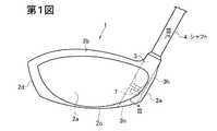
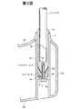
第1図は実施の形態に係るゴルフクラブのヘッド付近の正面図、第2図はゴルフクラブヘッドのヒール側の側面図である。第3図は第1図のIII−III線断面図、第4図はゴルフクラブの分解斜視図、第5図はホゼル、スペーサ及びシャフトケースの斜視図、第6図はスペーサ及びホゼルの構成図である。 FIG. 1 is a front view of the vicinity of a head of a golf club according to an embodiment, and FIG. 2 is a side view of the heel side of the golf club head. 3 is a cross-sectional view taken along the line III-III of FIG. 1, FIG. 4 is an exploded perspective view of the golf club, FIG. 5 is a perspective view of the hosel, spacer, and shaft case, and FIG. It is.
このゴルフクラブは、ヘッド1のホゼル3にシャフト4を、シャフトケース5、スペーサ8及びボルト7を介して取り付けたものである。 In this golf club, a shaft 4 is attached to a
このヘッド1は中空のウッド型のものであり、フェース部2aと、クラウン部2bと、ソール部2cと、トウ部2dと、ヒール部2eと、バック部2fとを有する。 The
第3図の通り、クラウン部2bのフェース部2a側かつヒール部2e側にホゼル3が設けられている。このホゼル3に連なるように、ホゼル3と同一内径の筒部3hがホゼル3と同軸状にソール部2cにまで延在している。この筒部3h内にシャフトケース5が挿入され、ボルト7によって固定されている。筒部3hには、筒部3hの軸心方向と垂直な仕切板部6が設けられている。この仕切板部6の上側にスペーサ8が配置されている。この仕切板部6及びスペーサ8に設けられたボルト挿通孔(開口)6a,8aにボルト7が下から上へ挿通され、シャフトケース5の雌螺子孔5aにねじ込まれている。 As shown in FIG. 3, the
第4,5図の通り、スペーサ8は外周形状が円筒形である。スペーサ8の上端面から下方に向ってシャフトケース挿入穴8bが設けられている。このシャフトケース挿入穴8bの内周面は、奥側(下端側)ほど小径となる正四角錐形となっており、スペーサ8の軸心と斜交する4面の斜面8k(第5図)が設けられている。対向する1対の斜面8k同士の交差角度(挟角)は10〜30°特に15〜20°程度が好適である。前記ボルト挿通孔8aの上端は、このシャフトケース挿入穴8bの底面に開口している。 As shown in FIGS. 4 and 5, the
第3〜5図の通り、シャフトケース5は、筒部3hよりも極くわずかに小径の円筒形部材であり、上端側から下端側に向って、シャフト4の挿入用の穴5hが設けられている。シャフト4は、このシャフト挿入穴5hに挿入され、接着剤によってシャフトケース5に固着されている。このシャフト挿入穴5hの深さは10mm以上、例えば10〜50mm特に20〜40mm程度が好ましい。 As shown in FIGS. 3 to 5, the
シャフトケース5の上端には外向き鍔状のフランジ部5bが設けられている。このフランジ部5bの上面は、上方ほど小径となるテーパ形状となっているが、これに限定されない。 An outwardly
第4,5図に示す通り、シャフトケース5の下部の外面は、下端ほど小径となる四角錐形(正確には切頭四角錐形)であり、4面の斜面5cが設けられている。斜面5cは、シャフトケース5の軸心線を挟んで対称に設けられている。対向する1対の斜面5c,5c同士の交差角度は、スペーサ8のホゼル挿入穴8bの斜面8k,8kの交差角度と同一である。シャフトケース5の斜面5cとホゼル挿入穴8bの斜面8kとの間に弾性体8A(第3図)を介在させ、がたつきを防止している。 As shown in FIGS. 4 and 5, the outer surface of the lower portion of the
スペーサ8のシャフトケース挿入穴8b及びシャフトケース5の下部の外周面は、この実施の形態では正四角錐形であるが、正三角錐形、正六角錐形、正八角錐形などの正多角錐形であってもよい。 The shaft
スペーサ8の軸心回りの回転を防止するためのストッパ部として、第6図の通り、仕切板部6の上面に凹部6bが設けられ、スペーサ8の下面に凸部8cが設けられ、該凹部6bと凸部8cとが係合している。スペーサ8の切削加工により凸部8cをスペーサ8と一体に形成してもよいが、スペーサ8の底面にダボ穴を設け、このダボ穴にダボピンを差し込み、接着、溶接、ろう付けなどによりダボピンを固着して凸部8cを形成するのが簡単で好ましい。 As a stopper portion for preventing the rotation of the
スペーサ8は、この凸部8cを凹部6bに差し込むようにして筒部3hの最奥部に配置され、好ましくは接着剤によって仕切板部6に対し接着される。なお、スペーサ8の下端外周部に面取りが施されており、余分な接着剤を側周面に回り込ませ易くしている。第5図の通り、スペーサ8の外周面には溝8mが周回して設けられており、この回り込んできた接着剤を収容可能としている。溝8mに収容された接着剤は、スペーサ8を固定するアンカーの役割を果すようになる。 The
ゴルフクラブを組み立てるには、予めスペーサ8を筒部3hの奥底部に配置し、接着剤で固着しておく。また、第4図のように、該シャフト4の先端にシャフトケース5を接着剤を用いて固着してシャフトケース・シャフト連結体としておく。好ましくは、この接着剤をシャフト4の先端部の外周面に塗着し、シャフトケース5のシャフト挿入穴5hの最奥部まで該シャフト4を差し込む。接着剤としてはエポキシ系接着剤などが好適である。 In order to assemble the golf club, the
なお、第3図では雌螺子孔5aがシャフトケース5を貫通していないが、第10図のシャフトケース5’のように雌螺子孔5aがシャフトケース5’を貫通してもよい。この場合には、シャフト4をシャフトケース5の穴5hに差し込んだときに空気が該雌螺子孔5aを通って流出する。第3図のように、雌螺子孔5aが非貫通の場合には、雌螺子孔5aと穴5hとを連通する空気抜き用の小孔を設けてもよい。 In FIG. 3, the
このシャフトケース・シャフト連結体の該シャフトケース5を、筒部3hに差し込み、シャフトケース5の先端をシャフトケース挿入穴8bに差し込み、斜面5c,8kを係合させる。次いで、ボルト7をボルト挿通孔6a,8aを通して雌螺子孔5aにねじ込む。 The
これにより、第3図の通り、シャフトケース5がヘッド1に固定される。シャフトケース5とシャフト4とは接着剤によって強固に接着されているので、これにより、シャフト4とヘッド1とが一体となったゴルフクラブが完成する。シャフトケース5の斜面5cとスペーサ8の斜面8kとが係合し、スペーサ8の凸部8cが仕切板部6の凹部6bに係合しているので、シャフト4及びシャフトケース5の周方向位相が正確に決まる。また、シャフト4及びシャフトケース5のトルク方向の固定剛性が高い。 Thereby, the
また、4面の斜面5cを設けてシャフトケース5の先端側を先細形としているので、それぞれ筒部3h内に挿入し易い。 Further, since the four
なお、スペーサ8は筒部3hの奥部にのみ配置される短い部材であり、重量が小さい。 The
本発明では、ゴルフクラブのシャフト交換も容易に行うことができる。 In the present invention, the shaft of the golf club can be easily replaced.
ゴルフクラブのシャフト交換を行うには、交換すべき新シャフトに、予め上記シャフトケース5と同型のシャフトケースを接着剤によって固着しておく。 In order to replace the shaft of the golf club, a shaft case of the same type as the
既存のゴルフクラブのボルト7を外し、旧シャフト4を旧シャフトケース5共々ヘッド1から取り外す。次いで、シャフトケース付きの新シャフト(シャフトケース・シャフト連結体)をヘッド1に差し込み、ボルト7によって固定する。 The
このようにシャフトの取り付けや交換を極めて簡単かつ迅速に行うことができる。なお、従来では、シャフトの交換に際し既存のゴルフクラブのホゼル部分を加熱して接着剤硬化物の組織を壊し、シャフトを抜いた後、新シャフトを接着剤で固着するようにしていたため、数時間〜1日程度の時間がかかっていたが、上記実施の形態では、予め新シャフトにシャフトケース5を接着剤で取り付けておくことにより、シャフト交換を数分程度で行うことができる。従って、シャフトケース付きの各種スペックのシャフトを用意しておき、同一のヘッド1に順次に異なるシャフトを取り付けて試打する様な利用方式が実現可能となる。 In this way, the shaft can be attached and replaced very easily and quickly. In the past, when the shaft was replaced, the hosel part of the existing golf club was heated to break the structure of the cured adhesive, and after the shaft was pulled out, the new shaft was fixed with an adhesive. Although it took about 1 day, in the above embodiment, the shaft can be replaced in several minutes by attaching the
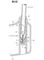
なお、第1〜6図では、シャフト4は筒部3hの軸心に対し同軸に配置されているが、第7図及び第8図の如く、このシャフト4の位置及び傾き方向は変更可能である。 1 to 6, the shaft 4 is arranged coaxially with the axial center of the
第7図のシャフトケース5Aは、シャフト挿入穴5hをシャフトケース5の軸心位置から偏心させたものである。シャフト挿入穴5hの軸心は、筒部3hの軸心と平行でかつそれから若干(例えば0.5〜4mm)離隔している。 The shaft case 5A shown in FIG. 7 has a
第8図のシャフトケース5Bは、シャフト挿入穴5hの軸心方向を筒部3hの軸心方向に対し傾斜させたものである。両軸心線の交差角度は0.1〜5.0°、特に0.25〜3.0°程度が好ましい。 The shaft case 5B in FIG. 8 is obtained by inclining the axial direction of the
なお、軸心線同士は交差しなくてもよく、「ねじれ」の関係にあってもよい。即ち、両者の軸心線は交わることがなく、一方の軸心線が他方の軸心線の近傍を通り抜ける関係であってもよい。 Note that the axial lines do not have to intersect each other and may have a “twisted” relationship. In other words, the two axes may not cross each other and one axis passes through the vicinity of the other axis.
第7図のシャフトケース5A又は第8図のシャフトケース5Bを用いることにより、シャフトのプログレッションやライ角などを調節することができる。 By using the shaft case 5A in FIG. 7 or the shaft case 5B in FIG. 8, the progression and lie angle of the shaft can be adjusted.
第7図のシャフトケース5Aを用いた場合、第7図に示すようにシャフト4を第5図の場合よりも偏心距離分だけフェース側に近づけることができる。 When the shaft case 5A of FIG. 7 is used, as shown in FIG. 7, the shaft 4 can be brought closer to the face side by an eccentric distance than the case of FIG.
この第7図に示す状態から、ボルト7を外してシャフトケース5Aを一旦筒部3hから抜き出し、90°、180°又は270°回すことによりシャフト4の位置をヒール側、バック側又はトウ側に平行移動状に変更することができる。シャフト4の位置をトウ側又はヒール側とすることにより、シャフト軸心からヘッド重心までの距離が変更される。第7図では、ヘッドの重心とシャフト4との距離が最も大きく、それから180°回した状態では、ヘッドの重心とシャフト4との距離が最も小さくなる。シャフト4の位置をフェース側又はバック側とすることによりプログレッションが変更される。 From the state shown in FIG. 7, the
第8図のように、シャフト挿入穴5hを筒部3hの軸心に対し斜めとしたシャフトケース5Bを用いることにより、シャフト4の傾きを第1図及び第5図とは別のものとすることができる。 As shown in FIG. 8, the inclination of the shaft 4 is different from those shown in FIGS. 1 and 5 by using a shaft case 5B in which the
第8図では、シャフト4の軸心線が筒部3hの軸心線に対してフェース側に傾いている。第8図の状態からシャフトケース5を90°、180°又は270°回すことにより、シャフト4の傾き方向を変えることができる。即ち、シャフト4をヒール側に傾けたり、トウ側に傾けたり、バック側へ傾けたりすることができる。 In FIG. 8, the axis of the shaft 4 is inclined to the face side with respect to the axis of the
このようにシャフト4の傾きの向きを変えることによりライ角及びスライス角を変えることができる。 Thus, the lie angle and the slice angle can be changed by changing the direction of inclination of the shaft 4.
ライ角に関して説明すれば、シャフト4を最もヒール側に傾けた場合が最も小さく、フラットライであり、最もトウ側とした場合がアップライである。 As for the lie angle, the case where the shaft 4 is inclined to the heel side is the smallest, the flat lie is the case, and the case where the shaft 4 is the toe side is the up lie.
スライス角に関して説明すれば、最もフェース側に傾いた第8図ではフェース面が最も閉じたフックフェースとなり、これと反対に最も後方へ傾けることによりフェース面が最もオープンとなったスライスフェースとなる。 Referring to the slice angle, in FIG. 8 which is inclined to the most face side, the face face is the most closed hook face, and on the contrary, the face face is the most open slice face by tilting backward most.
このように、第8図のシャフトケース5Bを用いることにより、ヘッド1に対するシャフト4の傾き方向を変更することができ、ライ角及びスライス角を変えることができる。 Thus, by using the shaft case 5B of FIG. 8, the inclination direction of the shaft 4 with respect to the
このゴルフクラブにあっては、フランジ部5bをテーパ形としているが、平たいフランジ形の拡径部を設け、その上側にフェルールを装着するようにしてもよい。 In this golf club, the
なお、シャフトケース5とシャフトケース挿入穴8bとの間にゴム、エラストマー、合成樹脂などよりなる薄片状の弾性体8Aを介在させているので、インパクト時の衝撃や振動を吸収することができる。 In addition, since the flaky
この実施の形態では、スペーサ8の回り止め用の凸部8cと凹部6bをダボピン及びダボ穴状に設けているが、第9図(a)〜(d)のように、スペーサ8の底面を径方向に延在する凸条8eと、仕切板部6の上面を径方向に延在する凹条6eとを設けてもよい。凸条8eはスペーサ8と一体に形成されてもよいが、第9図(e)の通り、スペーサ8の底面に凹溝8gを形成し、この凹溝8gに棒状部8fを接着、溶接、ろう付けなどにより固着することにより形成されてもよい。第9図(a),(b)では凸条8e及び凹条6eは直径方向に延在しているが、半径方向に延在してもよい。なお、第9図(c)は第9図(a)のC−C線断面図、第9図(d)は第9図(b)のD−D線断面図である。第9図(e)は、第9図(c)と同様部分の断面図である。 In this embodiment, the
上記シャフトケース及びボルトは金属製とされることが好ましく、特にアルミ又はチタンもしくはそれらの合金よりなることが好ましい。スペーサ8は、金属、FRP又は合成樹脂製であることが好ましい。 The shaft case and the bolt are preferably made of metal, and particularly preferably made of aluminum, titanium, or an alloy thereof. The
ヘッドの材質は特に限定されないが、ウッド型ゴルフクラブヘッドの場合、例えばチタン合金やアルミ合金、ステンレス等とすることができる。 The material of the head is not particularly limited, but in the case of a wood type golf club head, for example, a titanium alloy, an aluminum alloy, stainless steel or the like can be used.
上記実施の形態ではスペーサ8及びシャフトケース5,5A,5Bに正四角錐形となるように4面の斜面を設けているが、斜面の数が3又は5以上の正多角錐形でもよい。また、シャフトケースの先端側及びシャフトケース挿入穴の奥部を星型等の凹多角形断面形状やギヤ歯形断面形状としてもよい。 In the above embodiment, the
なお、シャフト4に取り付けるグリップとして、断面が非真円形のものを用いることがある。例えば、グリップ外周面のうちアドレス状態で地面を指向する下側面をその他の面よりも膨出した形状とすることがある。このような場合、シャフトケース5A,5Bの向きを変えたときに、グリップ膨出部が地面側とならないことがある。そこで、本発明では、断面真円形のグリップを用いるのが好ましい。 In addition, as a grip attached to the shaft 4, a grip having a non-circular cross section may be used. For example, the bottom surface of the grip outer peripheral surface that faces the ground in the address state may have a shape that bulges more than other surfaces. In such a case, when the directions of the shaft cases 5A and 5B are changed, the grip bulging portion may not be on the ground side. Therefore, in the present invention, it is preferable to use a grip having a perfectly circular cross section.
上記実施の形態ではゴルフクラブヘッドはウッド型であるが、ユーティリティ型、アイアン型、パターなどのいずれのタイプのゴルフクラブヘッドにも本発明を適用することができる。 In the above embodiment, the golf club head is a wood type, but the present invention can be applied to any type of golf club head such as a utility type, an iron type, or a putter.
1 ヘッド
2a フェース部
2e ヒール部
3 ホゼル
3b 筒部
4 シャフト
5,5A,5B シャフトケース
5a 雌ねじ孔
5h シャフト挿入孔
6 仕切板部
7 ボルト
8 スペーサ
8b シャフトケース挿入穴DESCRIPTION OF
Claims (7)
Translated fromJapanese該シャフトの先端に略筒形のシャフトケースが固着され、
前記ヘッドのホゼルの筒部内に該シャフトケースが挿入され、
該筒部の下部に仕切板部が設けられ、
該シャフトケースの先端と該仕切板部との間にスペーサが介在されており、
該シャフトケースが該スペーサに回転不能に係合しており、
該スペーサ及び該仕切板部には、該スペーサの回転を阻止するためのストッパ部が設けられており、
該仕切板部及びスペーサに設けられたボルト挿通孔に対し該ヘッドのソール側から差し込まれたボルトが該シャフトケースにねじ込まれ、これによりシャフトケースが該ヘッドに固定されていることを特徴とするゴルフクラブ。In a golf club with a head attached to the tip of the shaft,
A substantially cylindrical shaft case is fixed to the tip of the shaft,
The shaft case is inserted into the cylindrical portion of the hosel of the head,
A partition plate portion is provided at the bottom of the cylindrical portion,
A spacer is interposed between the tip of the shaft case and the partition plate portion,
The shaft case is non-rotatably engaged with the spacer;
The spacer and the partition plate portion are provided with a stopper portion for preventing rotation of the spacer,
Bolts inserted from the sole side of the head into bolt insertion holes provided in the partition plate portion and the spacer are screwed into the shaft case, whereby the shaft case is fixed to the head. Golf club.
前記シャフトケースの下端側及びシャフトケース挿入穴が多角断面形状となっており、両者が係合していることを特徴とするゴルフクラブ。In any one of Claims 1 thru | or 4, The shaft case insertion hole is provided in the said spacer,
A golf club characterized in that a lower end side of the shaft case and a shaft case insertion hole have a polygonal cross-sectional shape, and both are engaged.
前記ボルトを外して前記スペーサからシャフトケースを離反させ、該シャフトケースを回転させてシャフト挿入穴の位置又はシャフトの傾きを変更した後、再度該シャフトケースをスペーサと係合させ、前記ボルトによって固定することを特徴とするゴルフクラブの特性調節方法。A method for adjusting the characteristics of a golf club according to any one of claims 1 to 5,
Remove the bolt, move the shaft case away from the spacer, rotate the shaft case to change the position of the shaft insertion hole or the inclination of the shaft, and then engage the shaft case with the spacer again and fix with the bolt A method for adjusting characteristics of a golf club, comprising:
予め新たなシャフトを新たなシャフトケースに固着して新たなシャフトケース・シャフト連結体を作成しておき、
ゴルフクラブに取り付けられているシャフトケース・シャフト連結体をヘッドから取り外し、このヘッドに新たなシャフトケース・シャフト連結体を取り付けることを特徴とするゴルフクラブの特性調節方法。A method for adjusting characteristics by replacing the shaft of the golf club according to any one of claims 1 to 5 with a new shaft,
A new shaft is fixed to a new shaft case in advance to create a new shaft case / shaft assembly,
A method for adjusting characteristics of a golf club, comprising: removing a shaft case / shaft coupling body attached to the golf club from the head; and attaching a new shaft case / shaft coupling body to the head.
Priority Applications (2)
| Application Number | Priority Date | Filing Date | Title |
|---|---|---|---|
| JP2011028744AJP2012165864A (en) | 2011-02-14 | 2011-02-14 | Golf club and method for adjusting characteristic of the same |
| US13/365,314US8795099B2 (en) | 2011-02-14 | 2012-02-03 | Golf club and method for adjusting characteristics of golf club |
Applications Claiming Priority (1)
| Application Number | Priority Date | Filing Date | Title |
|---|---|---|---|
| JP2011028744AJP2012165864A (en) | 2011-02-14 | 2011-02-14 | Golf club and method for adjusting characteristic of the same |
Publications (1)
| Publication Number | Publication Date |
|---|---|
| JP2012165864Atrue JP2012165864A (en) | 2012-09-06 |
Family
ID=46637323
Family Applications (1)
| Application Number | Title | Priority Date | Filing Date |
|---|---|---|---|
| JP2011028744APendingJP2012165864A (en) | 2011-02-14 | 2011-02-14 | Golf club and method for adjusting characteristic of the same |
Country Status (2)
| Country | Link |
|---|---|
| US (1) | US8795099B2 (en) |
| JP (1) | JP2012165864A (en) |
Cited By (5)
| Publication number | Priority date | Publication date | Assignee | Title |
|---|---|---|---|---|
| US9050508B2 (en) | 2012-12-07 | 2015-06-09 | Bridgestone Sports Co., Ltd | Golf club and method for adjusting characteristics of the same |
| JP2015533335A (en)* | 2012-10-31 | 2015-11-24 | ナイキ イノベイト セー. フェー. | Releasable and interchangeable connection for golf club head and shaft |
| US10716972B1 (en)* | 2019-03-18 | 2020-07-21 | Barry Lyn Holtzman | Offset golf shaft and coupling apparatus |
| US11090530B1 (en)* | 2020-10-10 | 2021-08-17 | Anthony Aguilar | Interchangeable shafts for golf putter |
| KR20220059293A (en)* | 2020-11-02 | 2022-05-10 | 박유연 | golf putter head of module type |
Families Citing this family (7)
| Publication number | Priority date | Publication date | Assignee | Title |
|---|---|---|---|---|
| US8925790B1 (en)* | 2011-03-01 | 2015-01-06 | David Edel | Method for attaching the hosel to a putter head |
| JP5736985B2 (en)* | 2011-06-13 | 2015-06-17 | ブリヂストンスポーツ株式会社 | Manufacturing method of golf club head |
| JP2014113251A (en)* | 2012-12-07 | 2014-06-26 | Bridgestone Sports Co Ltd | Golf club and method for adjusting characteristics thereof |
| US9427638B2 (en)* | 2013-03-15 | 2016-08-30 | Brainstorm Golf, Inc. | Golf club configured for multiple adjustability |
| US9675854B2 (en) | 2014-05-09 | 2017-06-13 | Karsten Manufacturing Corporation | Golf clubs with adjustable loft and lie and methods of manufacturing golf clubs with adjustable loft and lie |
| JP6822072B2 (en)* | 2016-11-02 | 2021-01-27 | 住友ゴム工業株式会社 | Golf club |
| US12151147B2 (en) | 2021-09-21 | 2024-11-26 | Taylor Made Golf Company, Inc. | Golf club fitting systems |
Citations (5)
| Publication number | Priority date | Publication date | Assignee | Title |
|---|---|---|---|---|
| US2067556A (en)* | 1935-10-29 | 1937-01-12 | William L Wettlaufer | Golf club |
| JP2008029691A (en)* | 2006-07-31 | 2008-02-14 | Daiwa Seiko Inc | Golf club |
| JP2009291602A (en)* | 2008-05-16 | 2009-12-17 | Taylor Made Golf Co Inc | Attachable golf club head |
| JP2010051590A (en)* | 2008-08-28 | 2010-03-11 | Globeride Inc | Golf club |
| JP2010537730A (en)* | 2007-08-28 | 2010-12-09 | ナイキ インコーポレーティッド | Removable and replaceable connection for golf club head and shaft |
Family Cites Families (24)
| Publication number | Priority date | Publication date | Assignee | Title |
|---|---|---|---|---|
| US2219670A (en)* | 1939-01-25 | 1940-10-29 | William L Wettlaufer | Golf club |
| GB2197209B (en)* | 1986-11-06 | 1990-06-06 | Norman William Wharton | Golf club |
| JPH0614790Y2 (en)* | 1987-07-24 | 1994-04-20 | 国雄 山田 | Head attachment device for golf club |
| US5374062A (en)* | 1993-11-09 | 1994-12-20 | Kochevar; Rudolph J. | Swing weight with locking feature and golf club and method utilizing the same |
| JP2000005349A (en) | 1998-06-19 | 2000-01-11 | Akitaka Nakayama | Golf club facilitating shaft exchange and angle adjustment |
| JP2003070940A (en) | 2001-09-06 | 2003-03-11 | Fukuju Sato | Golf club head |
| US20040018886A1 (en)* | 2002-07-24 | 2004-01-29 | Burrows Bruce D. | Temporary golf club shaft-component connection |
| JP2006042951A (en) | 2004-08-02 | 2006-02-16 | Seiko S-Yard Co Ltd | Golf club |
| US7427239B2 (en)* | 2004-11-17 | 2008-09-23 | Callaway Golf Company | Golf club with interchangeable head-shaft connection |
| US20060287125A1 (en)* | 2004-11-17 | 2006-12-21 | Alan Hocknell | Golf Club with Interchangeable Head-Shaft Connection |
| US7335113B2 (en)* | 2004-11-17 | 2008-02-26 | Callaway Golf Company | Golf club with interchangeable head-shaft connection |
| US20080254909A1 (en) | 2007-04-13 | 2008-10-16 | Callinan Daniel S | Two-part hosel connection system for golf clubs |
| JP2010005197A (en) | 2008-06-27 | 2010-01-14 | Globeride Inc | Golf club |
| NZ561380A (en)* | 2007-09-10 | 2010-04-30 | Puku Ltd | An adjustable connector |
| JP5372486B2 (en) | 2007-12-18 | 2013-12-18 | アクシュネット カンパニー | Interchangeable shaft and club head connection system |
| TWM333209U (en)* | 2008-02-05 | 2008-06-01 | Advanced Int Multitech Co Ltd | Shaft and club head changing structure of golf club |
| US8029382B2 (en)* | 2008-03-24 | 2011-10-04 | Taylor Made Golf Company, Inc. | Golf-club shafts having selectable-stiffness tip regions, and golf clubs comprising same |
| US20100197422A1 (en)* | 2009-02-05 | 2010-08-05 | Nike, Inc. | Releasable and interchangeable connections for golf club heads and shafts |
| JP5353473B2 (en) | 2009-06-23 | 2013-11-27 | ブリヂストンスポーツ株式会社 | Golf club, head thereof, and characteristic adjusting method |
| JP4891379B2 (en)* | 2009-10-27 | 2012-03-07 | Sriスポーツ株式会社 | Golf club |
| JP2011156248A (en)* | 2010-02-03 | 2011-08-18 | Sri Sports Ltd | Golf club |
| CN201855543U (en)* | 2010-10-12 | 2011-06-08 | 复盛股份有限公司 | Golf club |
| US20120165111A1 (en)* | 2010-12-23 | 2012-06-28 | Cheng Michael H L | Apparatus for connecting a golf club shaft to a golf club head and golf clubs including the same |
| WO2013028885A2 (en)* | 2011-08-23 | 2013-02-28 | Nike International Ltd. | Releasable and interchangeable connections for golf club heads and shafts |
- 2011
- 2011-02-14JPJP2011028744Apatent/JP2012165864A/enactivePending
- 2012
- 2012-02-03USUS13/365,314patent/US8795099B2/ennot_activeExpired - Fee Related
Patent Citations (5)
| Publication number | Priority date | Publication date | Assignee | Title |
|---|---|---|---|---|
| US2067556A (en)* | 1935-10-29 | 1937-01-12 | William L Wettlaufer | Golf club |
| JP2008029691A (en)* | 2006-07-31 | 2008-02-14 | Daiwa Seiko Inc | Golf club |
| JP2010537730A (en)* | 2007-08-28 | 2010-12-09 | ナイキ インコーポレーティッド | Removable and replaceable connection for golf club head and shaft |
| JP2009291602A (en)* | 2008-05-16 | 2009-12-17 | Taylor Made Golf Co Inc | Attachable golf club head |
| JP2010051590A (en)* | 2008-08-28 | 2010-03-11 | Globeride Inc | Golf club |
Cited By (6)
| Publication number | Priority date | Publication date | Assignee | Title |
|---|---|---|---|---|
| JP2015533335A (en)* | 2012-10-31 | 2015-11-24 | ナイキ イノベイト セー. フェー. | Releasable and interchangeable connection for golf club head and shaft |
| US9050508B2 (en) | 2012-12-07 | 2015-06-09 | Bridgestone Sports Co., Ltd | Golf club and method for adjusting characteristics of the same |
| US10716972B1 (en)* | 2019-03-18 | 2020-07-21 | Barry Lyn Holtzman | Offset golf shaft and coupling apparatus |
| US11090530B1 (en)* | 2020-10-10 | 2021-08-17 | Anthony Aguilar | Interchangeable shafts for golf putter |
| KR20220059293A (en)* | 2020-11-02 | 2022-05-10 | 박유연 | golf putter head of module type |
| KR102428888B1 (en) | 2020-11-02 | 2022-08-04 | 박유연 | golf putter head of module type |
Also Published As
| Publication number | Publication date |
|---|---|
| US20120208653A1 (en) | 2012-08-16 |
| US8795099B2 (en) | 2014-08-05 |
Similar Documents
| Publication | Publication Date | Title |
|---|---|---|
| JP5353473B2 (en) | Golf club, head thereof, and characteristic adjusting method | |
| JP2012165864A (en) | Golf club and method for adjusting characteristic of the same | |
| JP5359586B2 (en) | Golf club and method for adjusting characteristics thereof | |
| JP5387351B2 (en) | Golf club head and golf club | |
| JP5401951B2 (en) | Golf club, characteristic adjustment method thereof and shaft exchange method | |
| JP5463864B2 (en) | Golf club head and golf club | |
| US7819754B2 (en) | Golf club with removable components | |
| US7115046B1 (en) | Golf club with interchangeable head-shaft connection | |
| JP5736985B2 (en) | Manufacturing method of golf club head | |
| US9586101B2 (en) | Golf club | |
| US9050508B2 (en) | Golf club and method for adjusting characteristics of the same | |
| US20070004527A1 (en) | Method for fitting golf clubs to a golfer | |
| JP2012152331A (en) | Golf club, method for changing shaft insertion depth and shaft replacement method | |
| JP5716592B2 (en) | Golf club and method for adjusting characteristics thereof | |
| KR20070021382A (en) | Multipurpose golf club with adjustable length and angle | |
| JP5447141B2 (en) | Golf club | |
| JP2014121461A (en) | Golf club and method for adjusting its characteristic | |
| JP2015029833A (en) | Golf club head | |
| JP5386932B2 (en) | Golf club, characteristic adjustment method thereof and shaft exchange method | |
| JP6175762B2 (en) | Golf club and method for adjusting characteristics thereof | |
| JP2011217916A (en) | Golf club and method of adjusting properties thereof |
Legal Events
| Date | Code | Title | Description |
|---|---|---|---|
| A621 | Written request for application examination | Free format text:JAPANESE INTERMEDIATE CODE: A621 Effective date:20140121 | |
| A977 | Report on retrieval | Free format text:JAPANESE INTERMEDIATE CODE: A971007 Effective date:20140910 | |
| A131 | Notification of reasons for refusal | Free format text:JAPANESE INTERMEDIATE CODE: A131 Effective date:20140930 | |
| A02 | Decision of refusal | Free format text:JAPANESE INTERMEDIATE CODE: A02 Effective date:20150217 |