JP2012165233A - Communication system, communication control method and communication device - Google Patents
Communication system, communication control method and communication deviceDownload PDFInfo
- Publication number
- JP2012165233A JP2012165233AJP2011024750AJP2011024750AJP2012165233AJP 2012165233 AJP2012165233 AJP 2012165233AJP 2011024750 AJP2011024750 AJP 2011024750AJP 2011024750 AJP2011024750 AJP 2011024750AJP 2012165233 AJP2012165233 AJP 2012165233A
- Authority
- JP
- Japan
- Prior art keywords
- communication
- port
- address information
- packet
- failure
- Prior art date
- Legal status (The legal status is an assumption and is not a legal conclusion. Google has not performed a legal analysis and makes no representation as to the accuracy of the status listed.)
- Granted
Links
Images


Landscapes
- Data Exchanges In Wide-Area Networks (AREA)
Abstract
Translated fromJapaneseDescription
Translated fromJapanese本発明は、ネットワーク障害発生時に通信経路を切り替える技術に関する。 The present invention relates to a technique for switching a communication path when a network failure occurs.
広域な通信網として、例えば図5に示すような、ツリー構成に装置冗長を持たせ、現用系通信網(0系)と予備系通信網(1系)を用意する構成がある。0系と1系の装置間は、複数の物理的な回線を仮想的に束ね1本の回線であるかのように扱うリンクアグリゲーション(LAG:Link Aggregation)で構成された共有リンクと呼ばれる迂回経路で接続されている。 As a wide-area communication network, for example, as shown in FIG. 5, there is a configuration in which device redundancy is provided in a tree configuration, and an active communication network (system 0) and a standby communication network (system 1) are prepared. A detour route called a shared link composed of link aggregation (LAG) that virtually bundles a plurality of physical lines and treats them as if they were one line between the system 0 and the
現用系通信網において障害が発生した場合、トラヒックは予備系通信網側に迂回するために共有リンクを通るが、どの物理的な回線を通るのかは、各種のLAG振り分け方式(VLAN分散、入力ポート分散等)に基づいて振り分けられる。 When a failure occurs in the active communication network, the traffic passes through the shared link in order to detour to the protection communication network side. The physical line to be passed depends on various LAG distribution methods (VLAN distribution, input port) Distribution).
しかしながら、現用系通信網において複数の障害が発生した場合に、既存のLAG振り分け方式では、トラヒックの流れ方によっては共有リンクで輻輳が発生してしまうという問題がある。以下、従来のLAG振り分け方式で発生する問題について説明する。 However, when a plurality of failures occur in the active communication network, the existing LAG distribution method has a problem that congestion occurs in the shared link depending on how traffic flows. Hereinafter, problems that occur in the conventional LAG distribution method will be described.
図6に、説明で用いるネットワークの構成を示す。図6に示すネットワークでは、スイッチSW1と通信装置A〜Eで現用系通信網を構成し、スイッチSW2と通信装置A2〜E2で予備系通信網を構成し、現用系通信網の各装置と予備系通信網の対応する各装置を迂回経路で接続している。スイッチSW1とスイッチSW2は、2本の通信回線#1,2をLAGで構成した共有リンクで接続される。共有リンクの通信回線#1,#2のそれぞれは、スイッチSW1のポート6,7に接続される。各装置間を結ぶ通信回線は1本あたり1Gbpsであり、共有リンクは仮想的に2Gbpsの回線となる。 FIG. 6 shows a network configuration used in the description. In the network shown in FIG. 6, the switch SW1 and the communication devices A to E constitute an active communication network, and the switch SW2 and the communication devices A2 to E2 constitute an auxiliary communication network. The corresponding devices of the local communication network are connected by a detour route. The switches SW1 and SW2 are connected by a shared link in which the two
図6では、通信装置A−D間のトラヒックT1、通信装置B−E間のトラヒックT2、通信装置B−C間のトラヒックT3の流れを図示している。トラヒックT1は、VLAN番号が10で、800Mbpsの帯域を使用し、トラヒックT2は、VLAN番号が20で、500Mbpsの帯域を使用し、トラヒックT3は、VLAN番号が30で、500Mbpsの帯域を使用する。 FIG. 6 illustrates the flow of traffic T1 between the communication apparatuses A and D, traffic T2 between the communication apparatuses B and E, and traffic T3 between the communication apparatuses B and C. Traffic T1 has a VLAN number of 10 and uses a band of 800 Mbps, traffic T2 uses a VLAN number of 20 and a band of 500 Mbps, and traffic T3 uses a band of
まず、LAG振り分け方式としてVLAN分散方式を用いた場合について説明する。VLAN分散方式は、VLANの設定に応じて迂回する通信回線を設定する。例えば、図6において、振り分けの設定が、VLAN10,20をポート6に接続された通信回線#1、VLAN30をポート7に接続された通信回線#2であったとする。この設定により、ネットワーク障害が発生したときは、VLAN10,20のトラヒックは通信回線#1へ迂回し、VLAN30のトラヒックは通信回線#2へ迂回する。 First, the case where the VLAN distribution method is used as the LAG distribution method will be described. In the VLAN distribution method, a detour communication line is set according to the VLAN setting. For example, in FIG. 6, it is assumed that the distribution setting is
ここで、ネットワークに障害が発生した場合のトラヒックの流れを具体的に説明する。図7に示すように、スイッチSW1と通信装置Aを結ぶ通信回線、およびスイッチSW1と通信装置Bを結ぶ通信回線の2箇所で障害が発生した場合、障害が発生していた箇所を流れていたトラヒックT1,T2,T3は、トラヒックT1はVLAN番号が10であるので共有リンクの通信回線#1を経由し、トラヒックT2はVLAN番号が20であるので共有リンクの通信回線#1を経由し、トラヒックT3はVLAN番号が30であるので共有リンクの通信回線#2を経由する。この場合、トラヒックT1の帯域は800MbpsでトラヒックT2の帯域は500Mbpsであるので、合計1.3Gbpsとなり共有リンクの通信回線#1で輻輳が発生してしまう。 Here, the flow of traffic when a failure occurs in the network will be specifically described. As shown in FIG. 7, when a failure occurs in two places, that is, a communication line connecting the switch SW1 and the communication device A and a communication line connecting the switch SW1 and the communication device B, the portion where the failure occurred is flowing. The traffic T1, T2, T3 is routed through the shared link
続いて、入力ポート分散方式を用いた場合について説明する。入力ポート分散方式は、トラヒックの入力ポートに応じて迂回する回線を設定する。例えば、図6において、振り分けの設定が、ポート4,5をポート6に接続された通信回線#1、ポート3をポート7に接続された通信回線#2であったとする。この設定により、ネットワーク障害が発生したときは、ポート4,5から入力されたトラヒックは通信回線#1へ迂回し、ポート3から入力されたトラヒックは通信回線#2へ迂回する。 Next, a case where the input port distribution method is used will be described. In the input port distribution method, a detour line is set according to the traffic input port. For example, in FIG. 6, it is assumed that the distribution setting is
この場合も、スイッチSW1と通信装置Aとを結ぶ通信回線、スイッチSW1と通信装置Bとを結ぶ通信回線の2箇所で障害が発生したときには図7に示すようなトラヒックの流れとなり、共有リンクの通信回線#1で輻輳が発生してしまう。 Also in this case, when a failure occurs in two places, a communication line connecting the switch SW1 and the communication apparatus A and a communication line connecting the switch SW1 and the communication apparatus B, the traffic flow as shown in FIG. Congestion occurs in
このように、VLAN分散方式や入力ポート分散方式でLAG振り分けを行った場合、トラヒックの帯域によっては共有リンクで輻輳が発生してしまうことがある。 Thus, when LAG distribution is performed by the VLAN distribution method or the input port distribution method, congestion may occur in the shared link depending on the traffic band.
また、予めトラヒックが分散できるように、ネットワークに接続される通信端末のMACアドレスを登録することも考えられるが、これは現実的ではない。 Further, it is possible to register the MAC address of a communication terminal connected to the network so that traffic can be distributed in advance, but this is not realistic.
本発明は、上記に鑑みてなされたものであり、複数の通信回線により構成された迂回経路での輻輳の発生を抑制することを目的とする。 The present invention has been made in view of the above, and an object of the present invention is to suppress the occurrence of congestion in a detour route configured by a plurality of communication lines.
第1の本発明に係る通信システムは、入力したパケットに含まれるアドレス情報に基づいて当該パケットを送出すべき通信回線を判定して送出する通信装置を現用系通信網及び予備系通信網のそれぞれに配置し、当該通信装置の間を複数の通信回線で接続して迂回経路を構成し、前記現用系通信網側の通信装置に接続された現用系の通信回線に障害が発生したときに当該通信回線を流れるパケットを前記迂回経路に流す通信システムであって、前記現用系通信網側の通信装置は、通信回線を接続してパケットを入出力する複数のポートと、前記ポートと前記アドレス情報とを対応付けて記憶する蓄積手段と、前記蓄積手段を参照して入力したパケットを送出すべきポートを判定し送出する転送手段と、前記ポートに接続された通信回線の障害を検出する検出手段と、前記検出手段が障害を検出したときに、障害が検出された前記ポートに対応付けて記憶された前記アドレス情報を前記蓄積手段から読み出し、当該アドレス情報を前記迂回経路を構成する通信回線のいずれかが接続された別のポートと対応付けて前記蓄積手段に記憶させるとともに、当該アドレス情報を前記別のポートに接続された通信回線を介して予備系通信網側の通信装置へ通知する複製手段と、を有し、前記予備系通信網側の通信装置は、前記迂回経路を構成する通信回線のいずれかから前記アドレス情報を受信した場合、当該アドレス情報を送信元のアドレス情報として有するパケットは前記迂回経路を構成する通信回路のうち前記アドレス情報を受信した通信回線へ送出するように設定する設定手段を有することを特徴とする。 In the communication system according to the first aspect of the present invention, a communication apparatus for determining and transmitting a communication line to which the packet is to be transmitted based on address information included in the input packet is provided for each of the active communication network and the standby communication network. The communication device is connected by a plurality of communication lines to form a detour path, and when a failure occurs in the active communication line connected to the communication device on the active communication network side, A communication system for flowing a packet flowing through a communication line to the bypass route, wherein the communication device on the active communication network side connects a communication line and inputs / outputs packets, the port and the address information Storing means in association with each other, transfer means for determining and sending out a port to which a packet inputted with reference to the storage means should be sent, and failure of a communication line connected to the port A detecting means for detecting, and when the detecting means detects a failure, the address information stored in association with the port where the failure is detected is read from the storage means, and the address information is configured as the detour path A communication device on the standby communication network side through the communication line connected to the other port and storing the address information in the storage means in association with another port to which any of the communication lines connected is connected A copy unit for notifying to the backup communication network, when the communication device on the backup communication network side receives the address information from any of the communication lines constituting the bypass route, The packet which has as information has a setting means which sets so that it may send out to the communication line which received the said address information among the communication circuits which comprise the said detour route It is characterized in.
第2の本発明に係る通信制御方法は、入力したパケットに含まれるアドレス情報に基づいて当該パケットを送出すべき通信回線を判定して送出する通信装置を現用系通信網及び予備系通信網のそれぞれに配置し、当該通信装置の間を複数の通信回線で接続して迂回経路を構成し、前記現用系通信網側の通信装置に接続された現用系の通信回線に障害が発生したときに当該通信回線を流れるパケットを前記迂回経路に流す通信制御方法であって、前記現用系通信網側の通信装置による、通信回線を接続してパケットを入出力するポートと前記アドレス情報を対応付けて記憶する蓄積手段を参照して入力したパケットを送出すべきポートを判定し送出するステップと、前記ポートに接続された通信回線の障害を検出するステップと、前記検出するステップにおいて障害を検出したときに、障害が検出された前記ポートに対応付けて記憶された前記アドレス情報を前記蓄積手段から読み出し、当該アドレス情報を前記迂回経路を構成する通信回線のいずれかが接続された別のポートと対応付けて前記蓄積手段に記憶させるとともに、当該アドレス情報を前記別のポートに接続された通信回線を介して予備系通信網側の通信装置へ通知するステップと、を有し、前記予備系通信網側の通信装置による、前記迂回経路を構成する通信回線のいずれかから前記アドレス情報を受信した場合、当該アドレス情報を送信元のアドレス情報として有するパケットは前記迂回経路を構成する通信回路のうち前記アドレス情報を受信した通信回線へ送出するように設定するステップを有することを特徴とする。 The communication control method according to the second aspect of the present invention provides a communication apparatus for determining a communication line to which a packet is to be transmitted based on address information included in the input packet and transmitting the communication device to the active communication network and the standby communication network. When a failure occurs in the active communication line connected to the communication device on the active communication network side, each of the communication devices is connected by a plurality of communication lines to form a detour path. A communication control method for flowing a packet flowing through the communication line to the bypass path, wherein the communication device on the active communication network side associates the communication line and inputs / outputs a packet and associates the address information Determining and transmitting a port to which an input packet should be transmitted with reference to storage means for storing; detecting a failure in a communication line connected to the port; and detecting When a failure is detected in the step, the address information stored in association with the port where the failure is detected is read from the storage means, and the address information is connected to one of the communication lines constituting the bypass path And storing in the storage means in association with the other port, and notifying the address information to a communication device on the backup communication network side via a communication line connected to the other port. When the address information is received from any of the communication lines constituting the bypass path by the communication device on the standby communication network side, a packet having the address information as the address information of the transmission source uses the bypass path. A step of setting the address information to be transmitted to the received communication line in the communication circuit to be configured; .
第3の本発明に係る通信装置は、入力したパケットに含まれるアドレス情報に基づいて当該パケットを送出すべき通信回線を判定して送出する通信装置であって、予備系通信網側の通信装置との間を複数の通信回線で接続して迂回経路を構成し、通信回線を接続してパケットを入出力する複数のポートと、前記ポートと前記アドレス情報とを対応付けて記憶する蓄積手段と、前記蓄積手段を参照して入力したパケットを送出すべきポートを判定し送出する転送手段と、前記ポートに接続された通信回線の障害を検出する検出手段と、前記検出手段が障害を検出したときに、障害が検出された前記ポートに対応付けて記憶された前記アドレス情報を前記蓄積手段から読み出し、当該アドレス情報を前記迂回経路を構成する通信回線のいずれかが接続された別のポートと対応付けて前記蓄積手段に記憶させるとともに、当該アドレス情報を前記別のポートに接続された通信回線を介して予備系通信網側の通信装置へ通知する複製手段と、を有することを特徴とする。 A communication apparatus according to a third aspect of the present invention is a communication apparatus for determining and transmitting a communication line to which the packet is to be transmitted based on address information included in the input packet, the communication apparatus on the standby communication network side A plurality of ports that are connected to each other by a plurality of communication lines to form a detour path, connect the communication lines and input / output packets, and storage means that associates and stores the ports and the address information; A transfer unit that determines and sends out a port to which a packet input by referring to the storage unit is to be sent, a detection unit that detects a failure of a communication line connected to the port, and the detection unit detects a failure. When the address information stored in association with the port in which a failure has been detected is read from the storage means, the address information is read from any of the communication lines constituting the detour path. And storing in the storage means in association with another port that is continued, duplication means for notifying the address information to the communication device on the backup communication network side via a communication line connected to the other port, It is characterized by having.
本発明によれば、複数の通信回線により構成された迂回経路での輻輳の発生を抑制することができる。 ADVANTAGE OF THE INVENTION According to this invention, generation | occurrence | production of the congestion by the detour route comprised by the some communication line can be suppressed.
以下、本発明の実施の形態について図面を用いて説明する。 Hereinafter, embodiments of the present invention will be described with reference to the drawings.
図1は、本実施の形態における通信装置の構成を示す機能ブロック図である。同図に示す通信装置1は、複数の通信部11、障害検出部12、およびテーブル複製部13を備える。各通信部11は、転送部111、FDBテーブル蓄積部112を備え、各通信部11のポート1,2,・・・,Nのそれぞれには、通信回線が接続される。接続される通信回線のうちの幾つか(例えば2つ)は、予備系通信網の通信装置に接続され、LAGで構成された共有リンクとなる。通信装置1は、例えばL2スイッチなどである。 FIG. 1 is a functional block diagram showing a configuration of a communication apparatus according to the present embodiment. The
転送部111は、パケットのヘッダと各通信部11のFDBテーブル蓄積部112が保持するFDBテーブルに基づいてパケットを別の通信部11へ振り分けて送出する。また、通信部11に接続された経路からパケットを入力したときに、そのパケットに含まれる送信元情報を取得してFDBテーブルに登録する。具体的には、入力したパケットから送信元のMACアドレスを取得し、パケットを入力した通信部11が備えるFDBテーブル蓄積部112に登録する。これにより、ポート番号とMACアドレスが関連付けられるので、転送部111がパケットを入力すると、パケット内の宛先MACアドレスを参照し、宛先MACアドレスが登録されているFDBテーブルを保持する通信部11へパケットを振り分けることで、パケットを目的の送信先へ送出する。 The
障害検出部12は、通信部11に接続された通信回線に障害が発生したことを検出し、障害が発生した通信回線、ポートを特定する。 The
テーブル複製部13は、障害が発生した通信回線が接続されたポートを有する通信部11のFDBテーブル蓄積部112からFDBテーブルを読み出し、共有リンクを構成する通信回線が接続された、いずれかの通信部11のFDBテーブル蓄積部112に格納する。これにより、そのFDBテーブルに登録されたMACアドレス宛のパケットはFDBテーブルを格納した通信部11のポートに接続された通信回線を経由して予備系通信網側へ送出される。また、パケットの戻りの通信回線も指定するために、FDBテーブルのコピー先の通信部11に接続された通信回線を経由させて、コピーしたFDBテーブルに登録されたMACアドレスを予備系通信網側の通信装置に通知する。予備系通信網側の通信装置は、MACアドレスの通知を受信すると、そのMACアドレスが送信元のパケットは、通知を受信した通信回線へ送出するように設定する。 The
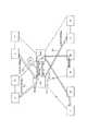
次に、本実施の形態における通信装置を用いて構築したネットワークについて説明する。図2は、本実施の形態における通信装置を用いて構築したネットワークの例を示す図である。 Next, a network constructed using the communication device in this embodiment will be described. FIG. 2 is a diagram illustrating an example of a network constructed using the communication device according to the present embodiment.
本実施の形態における通信装置であるスイッチSW1と通信装置A〜Eにより現用系通信網、スイッチSW2と通信装置A2〜E2により予備系通信網を構築し、現用系通信網の各装置と予備系通信網の対応する各装置を迂回経路として通信回線で接続している。スイッチSW1とスイッチSW2は、2本の通信回線#1,2をLAGで構成した共有リンクで接続される。各装置間を結ぶ通信回線の帯域は1本あたり1Gbpsであり、共有リンクは仮想的に2Gbpsの帯域を持つ回線となる。 An active communication network is constructed by the switch SW1 and the communication devices A to E, which are communication devices in the present embodiment, and a standby communication network is constructed by the switch SW2 and the communication devices A2 to E2, and each device of the active communication network and the standby system are constructed. Each corresponding device of the communication network is connected by a communication line as a bypass route. The switches SW1 and SW2 are connected by a shared link in which the two
ネットワークの端となる通信装置A〜Eそれぞれにはユーザ端末3A〜3Eが接続され、それぞれのユーザ端末3A〜3EのMACアドレスは、A,B,C,D,Eである。もちろん1つの通信装置に複数のユーザ端末を接続するものでもよいが、ここでは簡単のためにそれぞれ1つのユーザ端末のみ図示している。また、図2では、ユーザ端末3A−3D間、ユーザ端末3B−3E間、ユーザ端末3B−3C間にトラフィックT1〜T3が流れており、それぞれ800Mbps,500Mbps,500Mbpsの帯域が割り当てられているものとする。いずれの経路においても使用する帯域が1Gbpsを超えないので輻輳は発生しない。図2では、ユーザ端末3Aからユーザ端末3Dへ向かうパケットP1とユーザ端末3Dからユーザ端末3Aへ向かうパケットP2を図示している。パケットP1,P2は、宛先MACアドレス、送信元MACアドレスを有する。
スイッチSW1は、ポート1〜7の7つのポートを備え、ポート1〜5それぞれには通信装置A〜Eと接続する通信回線が接続され、ポート6,7には共有リンクを構成する通信回線#1,#2が接続されている。ポート1〜5それぞれに対応するFDBテーブル蓄積部112には、図2に示すFDBテーブルFDB1〜FDB5が登録されている。例えば、ポート1に対応するFDBテーブル蓄積部112には、ユーザ端末3AのMACアドレス:Aが登録されたFDBテーブルFDB1が格納されている。FDBテーブルには、スイッチSW1に入力されるパケットの送信元MACアドレスが登録される。例えば、図2のパケットP1がポート1から入力したときは、パケットP1の送信元MACアドレス(SA:A)から、ポート1に対応させてMACアドレス:AがFDBテーブルに登録される。また、パケットP1の宛先MACアドレス(DA:D)とFDBテーブルFDB4から、パケットP1は、MACアドレス:Dに対応するポート4へ送出される。 The switch SW1 includes seven
次に、スイッチSW1と通信装置Aを結ぶ通信回線、およびスイッチSW1と通信装置Bを結ぶ通信回線の2箇所で障害が発生したときの、スイッチSW1の動作について説明する。 Next, the operation of the switch SW1 when a failure occurs in two places, that is, a communication line connecting the switch SW1 and the communication apparatus A and a communication line connecting the switch SW1 and the communication apparatus B will be described.
図3は、本実施の形態における通信装置(スイッチSW1)がトラヒックの振り分けを設定する動作を説明する図である。 FIG. 3 is a diagram for explaining an operation in which the communication device (switch SW1) in this embodiment sets traffic distribution.
障害検出部12がポート1に接続された経路(通信装置Aとの間)の障害を検出すると(ステップS11)、テーブル複製部13は、ポート1に対応するFDBテーブル蓄積部112からFDBテーブルを読み出し、共有リンクが接続されたポート6に対応するFDBテーブル蓄積部112に読み出したFDBテーブルをコピーし、MACアドレス:Aをポート6に対応付ける(ステップS12)。これにより、宛先MACアドレスがAのパケットは、ポート6から送出されるようになる。 When the
そして、テーブル複製部13は、コピーされたMACアドレスの情報をポート6から送出し、通信回線#1を経由してスイッチSW2へ通知する(ステップS13)。スイッチSW2は、通知されたMACアドレスが送信元のパケットを受信した場合には、MACアドレスを通知してきた通信回線#1へそのパケットを転送するように設定する。この場合、送信元のMACアドレスがA、つまりユーザ端末3Aから送出されたパケットをスイッチSW2が受信すると、スイッチSW1のポート6に接続された通信回線#1へ転送する。なお、MACアドレスの通知には、LLDP(Link Layer Discovery Protocol)を用いることができる。 Then, the
一方、障害検出部12がポート2に接続された経路(通信装置Bとの間)の障害を検出すると(ステップS21)、テーブル複製部13は、ポート2に対応するFDBテーブル蓄積部112からFDBテーブルを読み出し、共有リンクが接続されたポート7に対応するFDBテーブル蓄積部112に読み出したFDBテーブルをコピーし、MACアドレス:Bをポート7に対応付ける(ステップS22)。これにより、宛先MACアドレスがBのパケットは、ポート7から送出されるようになる。なお、ポート6には既に別のポートのFDBテーブルがコピーされているので、ここではまだ利用されていないポート7にFDBテーブルがコピーされた。 On the other hand, when the
そして、テーブル複製部13は、コピーされたMACアドレスの情報をポート7から送出し、通信回線#2を経由してスイッチSW2へ通知する(ステップS23)。スイッチSW2は、通知されたMACアドレスが送信元のパケットを受信した場合には、MACアドレスを通知してきた通信回線#2へそのパケットを転送するように設定する。この場合、送信元のMACアドレスがB、つまりユーザ端末3Bから送出されたパケットをスイッチSW2が受信すると、スイッチSW1のポート7に接続された通信回線#2へ転送する。 Then, the
このように、トラヒックの迂回経路が設定される。 In this way, a traffic detour route is set.
図4に、トラヒックの振り分けを設定後のトラヒックの流れを示す。 FIG. 4 shows the flow of traffic after setting traffic distribution.
上述したように、スイッチSW1のポート6に対応するFDBテーブル蓄積部112には、ユーザ端末3AのMACアドレス:Aが登録され、ポート7に対応するFDBテーブル蓄積部112には、ユーザ端末3BのMACアドレス:Bが登録されている。その結果、スイッチSW1に入力される宛先MACアドレスがAのパケットはポート6から送出され、宛先MACアドレスがBのパケットはポート7から送出される。例えば、図4のユーザ端末3Dからユーザ端末3Aへ向かうパケットは宛先MACアドレスがAなので、スイッチSW1のポート6から送出されてスイッチSW2,A2を経由して通信装置Aに届く。ユーザ端末3Eからユーザ端末3Bへ向かうパケットは宛先MACアドレスがBなので、スイッチSW1のポート7から送出されてスイッチSW2,B2を経由して通信装置Bに届く。また、ユーザ端末3Cからユーザ端末3Bへ向かうパケットも宛先MACアドレスがBなので、スイッチSW1のポート7から送出されてスイッチSW2,B2を経由して通信装置Bに届く。 As described above, the MAC address: A of the
一方、スイッチSW2は、受信したパケットの送信元MACアドレスがスイッチSW1から通知されたMACアドレスである場合、そのMACアドレスの通知に用いられた通信回線#1,#2へ転送するように設定されている。例えば、ユーザ端末3Aからユーザ端末3Dへ向かうパケットは、送信元のMACアドレスがAであるので、通信回線#1から送出されてスイッチSW1を経由して通信装置Dに届く。ユーザ端末3Bからユーザ端末3Eへ向かうパケットは、送信元のMACアドレスがBであるので、通信回線#2から送出されてスイッチSW1を経由して通信装置Eに届く。また、ユーザ端末3Bからユーザ端末3Cへ向かうパケットは、送信元のMACアドレスがBであるので、通信回線#2から送出されてスイッチSW1を経由して通信装置Cに届く。 On the other hand, when the source MAC address of the received packet is the MAC address notified from the switch SW1, the switch SW2 is set to forward to the
このように、FDBテーブルをコピーすることにより、本来ならばポート1から送出されるパケットはポート6から送出され、ポート2から送出されるパケットはポート7から送出される。また、スイッチSW2からスイッチSW1へ向かうパケットもコピー元のポート1,2に応じて、本来ならばポート1から入力されるパケットはポート6から入力し、ポート2から入力されるパケットはポート7から入力される。その結果、障害が発生した通信回線を接続したポートを入出力するトラヒックをそのまま共有リンクを接続するポートへの入出力に振り分けることができるので、ポート6,7に接続される通信回線#1,#2それぞれには、障害が発生した通信回線の帯域である1Gbpsを超えるトラヒックが流れることはない。 In this way, by copying the FDB table, a packet that is originally transmitted from
なお、本実施の形態では、2本の通信回線で共有リンクを構成しているので同時に2箇所までの通信回線の故障に対応することはできるが、同時に3箇所以上の通信回線の故障には対応できない。3箇所以上の通信回線の故障には、迂回経路である共有リンクを3本以上の通信回線で構成することで対応可能である。 In the present embodiment, since a shared link is formed by two communication lines, it is possible to cope with failures in two or more communication lines at the same time. I can not cope. The failure of three or more communication lines can be dealt with by configuring a shared link as a detour path with three or more communication lines.
以上説明したように、本実施の形態によれば、障害検出部12が障害を検出したときに、テーブル複製部13が障害が検出された通信回線を接続した通信部11のFDBテーブル蓄積部112からFDBテーブルを読み出し、迂回経路である共有リンクを構成する通信回線#1,#2が接続されたいずれかの通信部11のFDBテーブル蓄積部112にコピーするとともに、コピーしたFDBテーブルに登録されたMACアドレスをFDBテーブルをコピーした通信部11に接続された通信回線#1,#2を経由して対向する通信装置に通知することにより、障害が検出されたポートを入出力していたパケットはFDBテーブルをコピーした通信部11のポートを入出力するので、複数の障害が検出された場合でも、共有リンクを接続するポートそれぞれを流れるトラヒックは、障害が検出されたポートそれぞれのトラヒックと変わらないので共有リンクで輻輳が発生しない。 As described above, according to the present embodiment, when the
1…通信装置
11…通信部
111…転送部
112…FDBテーブル蓄積部
12…障害検出部
13…テーブル複製部
A〜E,A2〜E2…通信装置
T1,T2,T3…トラヒック
3A〜3E…ユーザ端末DESCRIPTION OF
Claims (3)
Translated fromJapanese前記現用系通信網側の通信装置は、
通信回線を接続してパケットを入出力する複数のポートと、
前記ポートと前記アドレス情報とを対応付けて記憶する蓄積手段と、
前記蓄積手段を参照して入力したパケットを送出すべきポートを判定し送出する転送手段と、
前記ポートに接続された通信回線の障害を検出する検出手段と、
前記検出手段が障害を検出したときに、障害が検出された前記ポートに対応付けて記憶された前記アドレス情報を前記蓄積手段から読み出し、当該アドレス情報を前記迂回経路を構成する通信回線のいずれかが接続された別のポートと対応付けて前記蓄積手段に記憶させるとともに、当該アドレス情報を前記別のポートに接続された通信回線を介して予備系通信網側の通信装置へ通知する複製手段と、を有し、
前記予備系通信網側の通信装置は、
前記迂回経路を構成する通信回線のいずれかから前記アドレス情報を受信した場合、当該アドレス情報を送信元のアドレス情報として有するパケットは前記迂回経路を構成する通信回路のうち前記アドレス情報を受信した通信回線へ送出するように設定する設定手段を有すること
を特徴とする通信システム。Based on the address information included in the input packet, a communication device that determines and transmits a communication line to which the packet is to be transmitted is arranged in each of the active communication network and the standby communication network, and a plurality of communication devices are arranged between the communication devices. To establish a bypass route, and when a failure occurs in the active communication line connected to the communication device on the active communication network side, a packet flowing through the communication line is sent to the bypass route A communication system,
The communication device on the active communication network side is:
A plurality of ports for inputting and outputting packets by connecting communication lines;
Storage means for storing the port and the address information in association with each other;
Transfer means for determining and sending out a port to which a packet input with reference to the storage means is to be sent;
Detecting means for detecting a failure of a communication line connected to the port;
When the detection unit detects a failure, the address information stored in association with the port where the failure is detected is read from the storage unit, and the address information is one of the communication lines constituting the detour path. Is stored in the storage unit in association with another port connected to the communication port, and the address unit is notified to the communication device on the standby communication network side via the communication line connected to the other port; Have
The communication device on the standby communication network side is:
When the address information is received from any of the communication lines that constitute the bypass route, the packet having the address information as the source address information is the communication that has received the address information among the communication circuits that constitute the bypass route. A communication system characterized by comprising setting means for setting to transmit to a line.
前記現用系通信網側の通信装置による、
通信回線を接続してパケットを入出力するポートと前記アドレス情報を対応付けて記憶する蓄積手段を参照して入力したパケットを送出すべきポートを判定し送出するステップと、
前記ポートに接続された通信回線の障害を検出するステップと、
前記検出するステップにおいて障害を検出したときに、障害が検出された前記ポートに対応付けて記憶された前記アドレス情報を前記蓄積手段から読み出し、当該アドレス情報を前記迂回経路を構成する通信回線のいずれかが接続された別のポートと対応付けて前記蓄積手段に記憶させるとともに、当該アドレス情報を前記別のポートに接続された通信回線を介して予備系通信網側の通信装置へ通知するステップと、を有し、
前記予備系通信網側の通信装置による、
前記迂回経路を構成する通信回線のいずれかから前記アドレス情報を受信した場合、当該アドレス情報を送信元のアドレス情報として有するパケットは前記迂回経路を構成する通信回路のうち前記アドレス情報を受信した通信回線へ送出するように設定するステップを有すること
を特徴とする通信制御方法。Based on the address information included in the input packet, a communication device that determines and transmits a communication line to which the packet is to be transmitted is arranged in each of the active communication network and the standby communication network, and a plurality of communication devices are arranged between the communication devices. To establish a bypass route, and when a failure occurs in the active communication line connected to the communication device on the active communication network side, a packet flowing through the communication line is sent to the bypass route A communication control method,
By the communication device on the working communication network side,
Determining and sending out a port to which the input packet is to be sent with reference to a storage means for storing the address information in association with a port for connecting and receiving a packet by connecting a communication line;
Detecting a failure of a communication line connected to the port;
When a failure is detected in the detecting step, the address information stored in association with the port where the failure is detected is read from the storage unit, and the address information is selected from any of the communication lines constituting the detour path. Storing in the storage means in association with another port connected to the port, and notifying the address information to a communication device on the backup communication network side via a communication line connected to the other port; Have
By the communication device on the standby communication network side,
When the address information is received from any of the communication lines that constitute the bypass route, the packet having the address information as the source address information is the communication that has received the address information among the communication circuits that constitute the bypass route. A communication control method comprising a step of setting to transmit to a line.
予備系通信網側の通信装置との間を複数の通信回線で接続して迂回経路を構成し、
通信回線を接続してパケットを入出力する複数のポートと、
前記ポートと前記アドレス情報とを対応付けて記憶する蓄積手段と、
前記蓄積手段を参照して入力したパケットを送出すべきポートを判定し送出する転送手段と、
前記ポートに接続された通信回線の障害を検出する検出手段と、
前記検出手段が障害を検出したときに、障害が検出された前記ポートに対応付けて記憶された前記アドレス情報を前記蓄積手段から読み出し、当該アドレス情報を前記迂回経路を構成する通信回線のいずれかが接続された別のポートと対応付けて前記蓄積手段に記憶させるとともに、当該アドレス情報を前記別のポートに接続された通信回線を介して予備系通信網側の通信装置へ通知する複製手段と、
を有することを特徴とする通信装置。A communication device for determining and transmitting a communication line to which the packet should be transmitted based on address information included in the input packet,
Connect to communication devices on the standby communication network side with multiple communication lines to configure a detour route,
A plurality of ports for inputting and outputting packets by connecting communication lines;
Storage means for storing the port and the address information in association with each other;
Transfer means for determining and sending out a port to which a packet input with reference to the storage means is to be sent;
Detecting means for detecting a failure of a communication line connected to the port;
When the detection unit detects a failure, the address information stored in association with the port where the failure is detected is read from the storage unit, and the address information is one of the communication lines constituting the detour path. Is stored in the storage unit in association with another port connected to the communication port, and the address unit is notified to the communication device on the standby communication network side via the communication line connected to the other port; ,
A communication apparatus comprising:
Priority Applications (1)
| Application Number | Priority Date | Filing Date | Title |
|---|---|---|---|
| JP2011024750AJP5519549B2 (en) | 2011-02-08 | 2011-02-08 | COMMUNICATION SYSTEM, COMMUNICATION CONTROL METHOD, AND COMMUNICATION DEVICE |
Applications Claiming Priority (1)
| Application Number | Priority Date | Filing Date | Title |
|---|---|---|---|
| JP2011024750AJP5519549B2 (en) | 2011-02-08 | 2011-02-08 | COMMUNICATION SYSTEM, COMMUNICATION CONTROL METHOD, AND COMMUNICATION DEVICE |
Publications (2)
| Publication Number | Publication Date |
|---|---|
| JP2012165233Atrue JP2012165233A (en) | 2012-08-30 |
| JP5519549B2 JP5519549B2 (en) | 2014-06-11 |
Family
ID=46844189
Family Applications (1)
| Application Number | Title | Priority Date | Filing Date |
|---|---|---|---|
| JP2011024750AExpired - Fee RelatedJP5519549B2 (en) | 2011-02-08 | 2011-02-08 | COMMUNICATION SYSTEM, COMMUNICATION CONTROL METHOD, AND COMMUNICATION DEVICE |
Country Status (1)
| Country | Link |
|---|---|
| JP (1) | JP5519549B2 (en) |
Cited By (1)
| Publication number | Priority date | Publication date | Assignee | Title |
|---|---|---|---|---|
| CN105099905A (en)* | 2014-05-14 | 2015-11-25 | 日立金属株式会社 | Relay System and Switching Device |
Citations (1)
| Publication number | Priority date | Publication date | Assignee | Title |
|---|---|---|---|---|
| JP2009055074A (en)* | 2007-08-23 | 2009-03-12 | Nippon Telegraph & Telephone East Corp | Communication apparatus and communication control method |
- 2011
- 2011-02-08JPJP2011024750Apatent/JP5519549B2/ennot_activeExpired - Fee Related
Patent Citations (1)
| Publication number | Priority date | Publication date | Assignee | Title |
|---|---|---|---|---|
| JP2009055074A (en)* | 2007-08-23 | 2009-03-12 | Nippon Telegraph & Telephone East Corp | Communication apparatus and communication control method |
Non-Patent Citations (4)
| Title |
|---|
| CSND200401692026; 伊藤 玄蕃: '通信品質と信頼性のなぞを解く 徹底解明「よいネットワーク」の条件とは? 会社でできる信頼性向上の手段' NETWORK MAGAZINE 第9巻,第3号, 20040301, p.156〜157* |
| CSND200800057018; 那須野 洋一 他: 'パワーアップ講座 機能でわかる!レイヤー3スイッチ攻略術 第5回 サーバー接続のための機能 VRRP' 日経NETWORK 第94号, 20080128, p.144〜149* |
| JPN6014013160; 伊藤 玄蕃: '通信品質と信頼性のなぞを解く 徹底解明「よいネットワーク」の条件とは? 会社でできる信頼性向上の手段' NETWORK MAGAZINE 第9巻,第3号, 20040301, p.156〜157* |
| JPN6014013161; 那須野 洋一 他: 'パワーアップ講座 機能でわかる!レイヤー3スイッチ攻略術 第5回 サーバー接続のための機能 VRRP' 日経NETWORK 第94号, 20080128, p.144〜149* |
Cited By (3)
| Publication number | Priority date | Publication date | Assignee | Title |
|---|---|---|---|---|
| CN105099905A (en)* | 2014-05-14 | 2015-11-25 | 日立金属株式会社 | Relay System and Switching Device |
| JP2015220509A (en)* | 2014-05-14 | 2015-12-07 | 日立金属株式会社 | Relay system and switch device |
| CN105099905B (en)* | 2014-05-14 | 2019-06-04 | 日立金属株式会社 | Relay system and switching device |
Also Published As
| Publication number | Publication date |
|---|---|
| JP5519549B2 (en) | 2014-06-11 |
Similar Documents
| Publication | Publication Date | Title |
|---|---|---|
| CN101155109B (en) | Ethernet switching system and equipment | |
| JP7091923B2 (en) | Transfer device, transfer method and program | |
| US7751329B2 (en) | Providing an abstraction layer in a cluster switch that includes plural switches | |
| CN112565046B (en) | Synchronizing multicast router capabilities | |
| JP4729119B2 (en) | Communication device in label switching network | |
| JP3714238B2 (en) | Network transfer system and transfer method | |
| JP6165850B2 (en) | Enhanced protocol independent multicast (PIM) fast rerouting methodology using downstream notification packets | |
| JP5874608B2 (en) | Communication system and network relay device | |
| CN101595691B (en) | Pseudowire connectivity involving redundant remote scenarios using inter-rack backup connections | |
| JP5404938B2 (en) | COMMUNICATION DEVICE, COMMUNICATION SYSTEM, AND COMMUNICATION METHOD | |
| CN104662851A (en) | Enhancements to PIM fast re-route with upstream activation packets | |
| CN101999224A (en) | Redundant Ethernet automatic protection switching access to virtual private lan services | |
| CN103684953A (en) | Method and device for avoiding data traffic loss in an Ethernet ring multihomed, in an active-standby manner, to a virtual private LAN service transport network | |
| CN102546430A (en) | Method for redundant backup of network equipment, and routing equipment and system | |
| CN101252492A (en) | A method and device for accessing a multi-protocol label switching virtual private network | |
| JP2007525895A (en) | Recovery mechanism for network topology | |
| CN111885630B (en) | Data transmission method and communication device | |
| JP5929720B2 (en) | Communication system and network relay device | |
| JP2013211680A (en) | Communication device | |
| US7869351B2 (en) | Communication techniques and generic layer 3 automatic switching protection | |
| JP5519549B2 (en) | COMMUNICATION SYSTEM, COMMUNICATION CONTROL METHOD, AND COMMUNICATION DEVICE | |
| CN101656678A (en) | Method and device for transmitting data flows | |
| JP2006135723A (en) | Information relay device, information relay method, program, information communication system | |
| JP2015231091A (en) | COMMUNICATION SYSTEM, NETWORK DEVICE, AND COMMUNICATION CONTROL METHOD | |
| JP2009004854A (en) | Communications system |
Legal Events
| Date | Code | Title | Description |
|---|---|---|---|
| A621 | Written request for application examination | Free format text:JAPANESE INTERMEDIATE CODE: A621 Effective date:20130613 | |
| A977 | Report on retrieval | Free format text:JAPANESE INTERMEDIATE CODE: A971007 Effective date:20140214 | |
| TRDD | Decision of grant or rejection written | ||
| A01 | Written decision to grant a patent or to grant a registration (utility model) | Free format text:JAPANESE INTERMEDIATE CODE: A01 Effective date:20140401 | |
| A61 | First payment of annual fees (during grant procedure) | Free format text:JAPANESE INTERMEDIATE CODE: A61 Effective date:20140403 | |
| R150 | Certificate of patent or registration of utility model | Ref document number:5519549 Country of ref document:JP Free format text:JAPANESE INTERMEDIATE CODE: R150 | |
| R250 | Receipt of annual fees | Free format text:JAPANESE INTERMEDIATE CODE: R250 | |
| R250 | Receipt of annual fees | Free format text:JAPANESE INTERMEDIATE CODE: R250 | |
| R250 | Receipt of annual fees | Free format text:JAPANESE INTERMEDIATE CODE: R250 | |
| R250 | Receipt of annual fees | Free format text:JAPANESE INTERMEDIATE CODE: R250 | |
| R250 | Receipt of annual fees | Free format text:JAPANESE INTERMEDIATE CODE: R250 | |
| R250 | Receipt of annual fees | Free format text:JAPANESE INTERMEDIATE CODE: R250 | |
| R250 | Receipt of annual fees | Free format text:JAPANESE INTERMEDIATE CODE: R250 | |
| LAPS | Cancellation because of no payment of annual fees |