Movatterモバイル変換


[0]ホーム

URL:


JP2012163567A - Specimen analyzer - Google Patents

Specimen analyzer
Download PDF

Info

Publication number
JP2012163567A
JP2012163567AJP2012096129AJP2012096129AJP2012163567AJP 2012163567 AJP2012163567 AJP 2012163567AJP 2012096129 AJP2012096129 AJP 2012096129AJP 2012096129 AJP2012096129 AJP 2012096129AJP 2012163567 AJP2012163567 AJP 2012163567A
Authority
JP
Japan
Prior art keywords
error
sample
rack
measurement
unit
Prior art date
Legal status (The legal status is an assumption and is not a legal conclusion. Google has not performed a legal analysis and makes no representation as to the accuracy of the status listed.)
Granted
Application number
JP2012096129A
Other languages
Japanese (ja)
Other versions
JP5331916B2 (en
Inventor
Yuji Wakamiya
裕二 若宮
Tomohiro Okuzaki
智裕 奥崎
Hisato Takehara
久人 竹原
Current Assignee (The listed assignees may be inaccurate. Google has not performed a legal analysis and makes no representation or warranty as to the accuracy of the list.)
Sysmex Corp
Original Assignee
Sysmex Corp
Priority date (The priority date is an assumption and is not a legal conclusion. Google has not performed a legal analysis and makes no representation as to the accuracy of the date listed.)
Filing date
Publication date
Application filed by Sysmex CorpfiledCriticalSysmex Corp
Priority to JP2012096129ApriorityCriticalpatent/JP5331916B2/en
Publication of JP2012163567ApublicationCriticalpatent/JP2012163567A/en
Application grantedgrantedCritical
Publication of JP5331916B2publicationCriticalpatent/JP5331916B2/en
Activelegal-statusCriticalCurrent
Anticipated expirationlegal-statusCritical

Links

Images

Landscapes

Abstract

PROBLEM TO BE SOLVED: To allow a user to accurately and promptly resume a measurement after error recovery in the case where an error occurs in a specimen analyzer and the measurement is intercepted.SOLUTION: In the case where any error occurs during operation of a measuring unit, in a specimen analyzer, an error recovery icon 220 is displayed in a device status display area 202. In the case of an error in which a measurement can be resumed only by selecting a measurement start button 204, only a measurement start icon 220b is displayed in the device status display area 202. In the case of an error in which a measurement can be resumed if the measurement start button 204 is selected after rack reset, both a rack reset icon 220a and the measurement start icon 220b are displayed.

Description

Translated fromJapanese

本発明は、免疫分析装置、血液凝固測定装置等の検体を分析する検体分析装置に関する。  The present invention relates to a sample analyzer for analyzing a sample such as an immune analyzer and a blood coagulation measuring device.

病院や検査機関では、生体から採取される血液などの検体の性状についての項目を測定する検体分析装置が使用されている。下記特許文献1には、誤動作等のエラーが発生した場合に、制御装置の表示画面にエラーに関する説明やエラーの復旧方法を表示するようにした生体試料分析装置が開示されている。この装置では、ユーザーが表示画面に表示された説明等を読むことによってエラーの内容を認識し、復旧作業を行うことが可能となっている。  In hospitals and testing institutions, sample analyzers that measure items about the properties of samples such as blood collected from a living body are used.Patent Document 1 below discloses a biological sample analyzer that displays an error-related explanation and an error recovery method on a display screen of a control device when an error such as a malfunction occurs. In this apparatus, the user can recognize the content of the error by reading the description displayed on the display screen and perform the recovery operation.

特開2006−71649号公報JP 2006-71649 A

上記特許文献1の技術では、エラーに関する説明やエラーの復旧方法が表示画面に文字で表示されるだけであ、これだけでは一般のユーザーが、エラーの発生によって中断した測定を、エラー復旧後に正確且つ迅速に再開できない場合があった。In the technique ofPatent Document 1state, and are only recovery method descriptions and error about the error is displayed in characters on the display screen, this alone is generallyuser, a measurement was interrupted due to the occurrence of an error, correct after error recovery In some cases, itcould not beresumed quickly .

本発明は、このような実情に鑑みてなされたものであり、装置にエラーが発生して測定が中断した場合に、ユーザーが正確且つ迅速にエラー復旧後の測定再開を行うことができる検体分析装置を提供することを目的とする。The present invention has been made in view of such circumstances, if an errorhas interrupted the measurement occurs in the apparatus, the usercan accurately and rapidlymeasured resumed after error recovery An object is to provide a sample analyzer.

本発明は、検体を分析する検体分析装置であって、ラックを搬送する検体搬送部と、前記検体搬送部によって搬送されたラック上の検体を吸引して測定を行う測定部と、表示部と、前記表示部に、装置の状態を表示する装置状態表示エリアおよび測定開始を指示するための測定開始ボタンを含むメインウィンドウを表示させる表示制御手段と、を備え、エラーの発生によってラックの搬送および新たな検体の吸引が停止した場合、前記表示制御手段は、前記エラーが、ラックを再セットすることなくラックの搬送および検体吸引を再開可能なエラーである場合には、前記測定開始ボタンの操作を促す情報を前記装置状態表示エリアに表示させ、前記エラーが、ラックを再セットすることによりラックの搬送および検体吸引を再開可能なエラーである場合には、ラックの再セットを促す情報と、前記測定開始ボタンの操作を促す情報を、前記装置状態表示エリアに表示させることを特徴としている。The present invention provides a sample analyzer for analyzing a sample, a sample transport unit that transports a rack, a measurement unit that performs measurement by sucking a sample on a rack transported by the sample transport unit, a display unit, And a display control means for displaying a main window including an apparatus status display area for displaying the status of the apparatus and a measurement start button for instructing the start of measurement on the display section. When the aspiration of a new sample is stopped, the display control means operates the measurement start button when the error is an error that can restart the rack transport and the sample aspiration without resetting the rack. Is displayed in the device status display area, and the error is an error that can restart rack transportation and sample aspiration by resetting the rack. In some cases, the information prompting the resetting of the rack, the information prompting the operation of the measurement start button is characterized in thatto be displayed on the apparatus status display area.

前記測定部は、エラーの発生によってラックの搬送および新たな検体の吸引が停止した場合、エラー発生時に既に吸引した検体の測定を継続することが可能であり、前記表示制御手段は、前記エラーが、既に吸引された検体の測定が終了するまで、ラックの搬送および検体吸引を再開できないエラーである場合、前記測定開始ボタンが操作できないことを示唆する情報を前記装置状態表示エリアに表示させる構成であってもよい。The measurement unit can continue measurement of a sample that has already been aspirated when an error occurs when the transport of the rack and the aspiration of a new sample are stopped due to the occurrence of an error, and the display control means If the error is incapable of resuming rack transportation and sample aspiration until the measurement of the already aspirated sample is completed, information indicating that the measurement start button cannot be operated is displayed in the apparatus status display area. There may be.

前記ラックの再セットを促す情報が、ラックを示す画像を含む構成であってもよい。  The information that prompts the resetting of the rack may include an image showing the rack.

前記測定開始ボタンの操作を促す情報が、前記測定開始ボタンを示す画像を含む構成であってもよい。  The information that prompts the operation of the measurement start button may include an image indicating the measurement start button.

前記表示制御手段は、前記装置の状態に応じて、前記装置状態表示エリアの表示色を切り換えるように構成されていてもよい。The display control means may be configured to switch the display color of the device status display area according to the status of the device.

前記表示制御手段は、前記エラーが、ラックを再セットし、又はラックを再セットすることなく、ラックの搬送および検体吸引を再開可能なエラーである場合には、前記装置状態表示エリアを第1の表示色で表示させ、前記エラーが、ラックの搬送および検体吸引が再開できないエラーである場合には、前記装置状態表示エリアを第2の表示色で表示させる構成であってもよい。If the error is an error that can reset the rack or restart the rack transport and sample aspiration without resetting the rack, the display control means sets the device status display area to the first state. If the error is an error in which rack transport and sample aspiration cannot be resumed, the apparatus status display area may be displayed in the second display color.

前記表示制御手段は、エラーが発生しておらず、且つ、測定開始ボタンを操作することによって、ラックの搬送および検体吸引を開始できる状態にある場合には、前記装置状態表示エリアを第3の表示色で表示させる構成であってもよい。  The display control means displays the apparatus status display area in the third state when no error has occurred and when the transport of the rack and the sample aspiration can be started by operating the measurement start button. It may be configured to display in the display color.

前記表示制御手段は、エラーの発生によって、ラックの搬送および検体吸引が停止した場合、前記エラーを復旧するための復旧情報を含むヘルプウィンドウを、前記メインウィンドウの上に、前記測定開始ボタンおよび前記装置状態表示エリアに重ならないように表示させる構成であってもよい。When the rack transport and sample aspiration are stopped due to the occurrence of an error, the display control means displays a help window including recovery information for recovering the error on the main window, the measurement start button and the It may be configured to display so as not to overlap the device status display area.

前記エラーが、ラックを再セットすることによりラックの搬送および検体吸引を再開可能なエラーである場合、前記復旧情報は、ラックの再セットを促すメッセージを含む構成であってもよい。In a case where the error is an error that can restart rack transportation and sample aspiration by resetting the rack, the recovery information may include a message that prompts the user to reset the rack.

本発明によれば、装置にエラーが発生して測定が中断した場合に、ユーザーが、正確且つ迅速にエラー復旧後の測定再開を行うことができるAccording to the present invention,when an error occurs in the apparatus and the measurement is interrupted, the user can restart measurement after error recovery accurately and quickly .

本発明の検体分析装置の一実施の形態の全体構成を示す平面説明図である。It is a plane explanatory view showing the whole composition of one embodiment of the sample analyzer of the present invention.図1に示される免疫分析装置における測定ユニットの構成を示すブロック図である。It is a block diagram which shows the structure of the measurement unit in the immune analyzer shown by FIG.図1に示される免疫分析装置における制御装置のブロック図である。FIG. 2 is a block diagram of a control device in the immune analyzer shown in FIG. 1.図1に示される免疫分析装置を用いた免疫分析の全体フローを示す図である。It is a figure which shows the whole flow of the immunoassay using the immunoassay apparatus shown by FIG.免疫分析装置の動作状態チェック処理の手順を示すフローチャートである。It is a flowchart which shows the procedure of the operation state check process of an immune analyzer.制御装置によるエラー処理の手順を示すフローチャートである。It is a flowchart which shows the procedure of the error processing by a control apparatus.メインウィンドウ及び測定部ヘルプウィンドウを示す図である。It is a figure which shows a main window and a measurement part help window.メインウィンドウ、測定部ヘルプウィンドウ及び異常箇所ダイアログを示す図である。It is a figure which shows a main window, a measurement part help window, and an abnormal location dialog.測定部ヘルプウィンドウ及び異常箇所ダイアログの他の例を示す図である。It is a figure which shows the other example of a measurement part help window and an abnormal location dialog.測定部ヘルプウィンドウ及び異常箇所ダイアログの更に他の例を示す図である。It is a figure which shows the further another example of a measurement part help window and an abnormal location dialog.装置状態表示エリアのテキスト表示、表示色、エラー復帰用アイコン及び装置状態の対応関係を示すテーブルである。It is a table which shows the correspondence of the text display of a device status display area, a display color, an icon for error recovery, and a device status.

以下、添付図面を参照しつつ、本発明の検体分析装置の実施の形態を詳細に説明する。
[装置の全体構成]
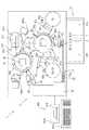
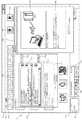
図1は、本発明の一実施の形態に係る免疫分析装置(検体分析装置)の全体構成を示す平面説明図である。
本発明の一実施の形態に係る免疫分析装置1は、血液等の検体(試料)を用いてB型肝炎、C型肝炎、腫瘍マーカ及び甲状腺ホルモン等種々の項目の検査を行うための装置である。この免疫分析装置1は、図1に模式的に示されるように、複数の機構(コンポーネント)からなる測定ユニット(測定部)2と、この測定ユニット2に電気的に接続された、データ処理ユニットである制御装置400(図3参照)とから主に構成されている。
Hereinafter, embodiments of a sample analyzer of the present invention will be described in detail with reference to the accompanying drawings.
[Overall configuration of the device]
FIG. 1 is an explanatory plan view showing the overall configuration of an immune analyzer (sample analyzer) according to an embodiment of the present invention.
Animmunoassay apparatus 1 according to an embodiment of the present invention is an apparatus for examining various items such as hepatitis B, hepatitis C, tumor marker, and thyroid hormone using a specimen (sample) such as blood. is there. As schematically shown in FIG. 1, theimmune analyzer 1 includes a measurement unit (measurement unit) 2 composed of a plurality of mechanisms (components) and a data processing unit electrically connected to themeasurement unit 2. And the control device 400 (see FIG. 3).

測定ユニット2は、検体搬送部(サンプラ)10と、緊急検体・チップ搬送部20と、ピペットチップ供給装置30と、チップ脱離部40と、検体分注アーム50と、試薬設置部60a及び60bと、1次反応部80a及び2次反応部80bと、試薬分注アーム90a、90b及び90cと、1次BF分離部100a及び2次BF分離部100bと、検出部120と、前記検体搬送部(サンプラ)10や検体分注アーム50等の機構の動作制御を行う本体制御部140(図2参照)とを備えている。なお、本実施の形態に係る免疫分析装置1では、検体分注アーム50により吸引及び吐出された血液等の検体が他の検体と混ざり合うのを抑制するために、検体の吸引及び吐出を行う度に、使い捨てのピペットチップの交換を行っている。  Themeasurement unit 2 includes a sample transport unit (sampler) 10, an emergency sample /chip transport unit 20, a pipettechip supply device 30, achip detachment unit 40, asample dispensing arm 50, andreagent setting units 60a and 60b.Primary reaction unit 80a andsecondary reaction unit 80b,reagent dispensing arms 90a, 90b and 90c, primaryBF separation unit 100a and secondaryBF separation unit 100b,detection unit 120, and sample transport unit (Sampler) 10 and a main body control unit 140 (see FIG. 2) that controls the operation of mechanisms such as thesample dispensing arm 50 and the like. In theimmunological analyzer 1 according to the present embodiment, the sample is aspirated and discharged in order to prevent the sample such as blood aspirated and discharged by thesample dispensing arm 50 from being mixed with other samples. Every time, disposable pipette tips are replaced.

この免疫分析装置1では、測定対象である血液等の検体に含まれる抗原に結合した捕捉抗体(R1試薬)に磁性粒子(R2試薬)を結合させた後に、結合(Bound)した抗原、捕捉抗体及び磁性粒子を1次BF(Bound Free)分離部100aの磁石に引き寄せることにより、未反応(Free)の捕捉抗体を含むR1試薬を除去する。そして、磁性粒子が結合した抗原と標識抗体(R3試薬)とを結合させた後に、結合(Bound)した磁性粒子、抗原及び標識抗体を2次BF分離部100bの磁石に引き寄せることにより、未反応(Free)の標識抗体を含むR3試薬を除去する。さらに、標識抗体との反応過程で発光する発光基質(R5試薬)を添加した後、標識抗体と発光基質との反応によって生じる発光量を測定する。このような過程を経て、標識抗体に結合する検体に含まれる抗原を定量的に測定している。  In thisimmunoanalyzer 1, after binding magnetic particles (R2 reagent) to a capture antibody (R1 reagent) bound to an antigen contained in a sample such as blood to be measured, the bound antigen and the capture antibody Then, the R1 reagent including the unreacted (Free) capture antibody is removed by attracting the magnetic particles to the magnet of the primary BF (Bound Free)separation unit 100a. Then, after binding the antigen to which the magnetic particles are bound and the labeled antibody (R3 reagent), the bound magnetic particles, the antigen and the labeled antibody are attracted to the magnet of the secondaryBF separation unit 100b, thereby causing unreacted The R3 reagent containing the (Free) labeled antibody is removed. Further, after adding a luminescent substrate (R5 reagent) that emits light during the reaction with the labeled antibody, the amount of luminescence generated by the reaction between the labeled antibody and the luminescent substrate is measured. Through such a process, the antigen contained in the specimen that binds to the labeled antibody is quantitatively measured.

[制御装置の構成]
制御装置400は、パーソナルコンピュータ401(PC)等からなり、図1に示されるように、制御部400aと、表示部400bと、キーボードやマウス等の入力部(入力手段)400cとを含んでいる。制御部400aは、測定ユニット2における各機構の動作制御を行うとともに、測定ユニット2で得られた検体の光学的な情報を分析するための機能を有している。この制御部400aは、CPU、ROM、RAM等からなる。また、表示部400bは、制御部400aで得られた分析結果等の情報を表示したり、また、後述するエラーウィンドウ(測定部ヘルプウィンドウ)210等を表示したりするために用いられる。
[Configuration of control device]
Thecontrol device 400 includes a personal computer 401 (PC) or the like, and includes acontrol unit 400a, adisplay unit 400b, and an input unit (input means) 400c such as a keyboard and a mouse, as shown in FIG. . Thecontrol unit 400a controls the operation of each mechanism in themeasurement unit 2 and has a function for analyzing optical information of the specimen obtained by themeasurement unit 2. Thecontrol unit 400a includes a CPU, a ROM, a RAM, and the like. Thedisplay unit 400b is used to display information such as analysis results obtained by thecontrol unit 400a, and to display an error window (measurement unit help window) 210 and the like described later.

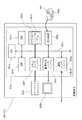
次に、制御装置400の構成について説明する。制御部400aは、図3に示されるように、CPU401aと、ROM401b,RAM401c及びハードディスク401d等からなる記憶部と、読出装置401eと、入出力インタフェース401fと、通信インタフェース401gと、画像出力インタフェース401hとから主として構成されている。
CPU401a、ROM401b、RAM401c、ハードディスク401d、読出装置401e、入出力インタフェース401f、通信インタフェース401g、及び画像出力インタフェース401hは、バス401iによって接続されている。
Next, the configuration of thecontrol device 400 will be described. As shown in FIG. 3, thecontrol unit 400a includes aCPU 401a, a storage unit including a ROM 401b, aRAM 401c, and a hard disk 401d, areading device 401e, an input /output interface 401f, acommunication interface 401g, and an image output interface 401h. Is mainly composed of
TheCPU 401a, ROM 401b,RAM 401c, hard disk 401d,reading device 401e, input /output interface 401f,communication interface 401g, and image output interface 401h are connected by a bus 401i.

CPU401aは、ROM401bに記憶されているコンピュータプログラム及びRAM401cにロードされたコンピュータプログラムを実行することが可能である。そして、後述するようなアプリケーションプログラム404aをCPU401aが実行することにより、コンピュータ401が制御装置400として機能する。
ROM401bは、マスクROM、PROM、EPROM、EEPROM等によって構成されており、CPU401aに実行されるコンピュータプログラム及びこれに用いるデータ等が記録されている。
TheCPU 401a can execute computer programs stored in the ROM 401b and computer programs loaded in theRAM 401c. Thecomputer 401 functions as thecontrol device 400 when theCPU 401a executes anapplication program 404a described later.
The ROM 401b is configured by a mask ROM, PROM, EPROM, EEPROM, or the like, and stores a computer program executed by theCPU 401a, data used for the same, and the like.

RAM401cは、SRAM又はDRAM等によって構成されている。RAM401cは、ROM401b及びハードディスク401dに記録されているコンピュータプログラムの読み出しに用いられる。また、これらのコンピュータプログラムを実行するときに、CPU401aの作業領域として利用される。  TheRAM 401c is configured by SRAM, DRAM, or the like. TheRAM 401c is used to read out computer programs recorded in the ROM 401b and the hard disk 401d. Further, when these computer programs are executed, they are used as a work area of theCPU 401a.

ハードディスク401dは、オペレーティングシステム及びアプリケーションプログラム等、CPU401aに実行させるための種々のコンピュータプログラム404a及びそのコンピュータプログラムの実行に用いるデータがインストールされている。例えば、測定オーダを登録するためのアプリケーションプログラムや、後述するように測定ユニット2のエラーに関する情報を取得したり、表示したりするためのアプリケーションプログラムもこのハードディスク401dにインストールされている。また、ハードディスク401dには、後述するような異常箇所画像、エラー詳細メッセージ、装置状態表示エリア202の背景画像、及びエラー復帰用アイコンが装置状態と関連づけられて記憶されている。  The hard disc 401d is installed withvarious computer programs 404a to be executed by theCPU 401a, such as an operating system and application programs, and data used for executing the computer programs. For example, an application program for registering a measurement order and an application program for acquiring and displaying information on errors of themeasurement unit 2 as described later are also installed in the hard disk 401d. The hard disc 401d stores an abnormal part image, an error detail message, a background image of the devicestatus display area 202, and an error recovery icon, which will be described later, in association with the device status.

読出装置401eは、フレキシブルディスクドライブ、CD−ROMドライブ、又はDVD−ROMドライブ等によって構成されており、可搬型記録媒体404に記録されたコンピュータプログラム又はデータを読み出すことができる。また、可搬型記録媒体404には、本実施の形態におけるアプリケーションプログラム404aが格納されており、コンピュータ401が、その可搬型記録媒体404からアプリケーションプログラム404aを読み出し、そのアプリケーションプログラム404aをハードディスク401dにインストールすることが可能である。  Thereading device 401e is configured by a flexible disk drive, a CD-ROM drive, a DVD-ROM drive, or the like, and can read a computer program or data recorded on theportable recording medium 404. Theportable recording medium 404 stores theapplication program 404a in the present embodiment, and thecomputer 401 reads theapplication program 404a from theportable recording medium 404 and installs theapplication program 404a on the hard disk 401d. Is possible.

なお、前記アプリケーションプログラム404aは、可搬型記録媒体404によって提供されるのみならず、電気通信回線(有線、無線を問わない)によってコンピュータ401と通信可能に接続された外部の機器から前記電気通信回線を通じて提供することも可能である。例えば、前記アプリケーションプログラム404aがインターネット上のサーバコンピュータのハードディスク内に格納されており、このサーバコンピュータにコンピュータ401がアクセスして、そのアプリケーションプログラム404aをダウンロードし、これをハードディスク401dにインストールすることも可能である。  Theapplication program 404a is not only provided by theportable recording medium 404, but also from an external device that is communicably connected to thecomputer 401 via a telecommunication line (whether wired or wireless). It is also possible to provide through. For example, theapplication program 404a is stored in a hard disk of a server computer on the Internet, and thecomputer 401 can access the server computer to download theapplication program 404a and install it on the hard disk 401d. It is.

ハードディスク401dには、例えば、米マイクロソフト社が製造販売するWindows(登録商標)等のグラフィカルユーザインタフェース環境を提供するオペレーティングシステムがインストールされている。以下の説明においては、本実施の形態におけるアプリケーションプログラム404aは前記オペレーティングシステム上で動作するものとしている。  An operating system that provides a graphical user interface environment, such as Windows (registered trademark) manufactured and sold by Microsoft Corporation, is installed in the hard disc 401d. In the following description, it is assumed that theapplication program 404a in the present embodiment operates on the operating system.

入出力インタフェース401fは、例えば、USB、IEEE1394、RS−232C等のシリアルインタフェース、SCSI、IDE、IEEE1284等のパラレルインタフェース、及びD/A変換器、A/D変換器等からなるアナログインタフェース等から構成されている。入出力インタフェース401fには、キーボード400cが接続されており、ユーザーがそのキーボード400cを使用することにより、コンピュータ401にデータを入力することが可能である。  The input /output interface 401f includes, for example, a serial interface such as USB, IEEE1394, RS-232C, a parallel interface such as SCSI, IDE, IEEE1284, and an analog interface including a D / A converter, an A / D converter, and the like. Has been. Akeyboard 400c is connected to the input /output interface 401f, and the user can input data to thecomputer 401 by using thekeyboard 400c.

通信インタフェース401gは、例えば、Ethernet(登録商標)インタフェースである。コンピュータ401は、その通信インタフェース401gにより、所定の通信プロトコルを使用して測定ユニット2との間でデータの送受信が可能である。
画像出力インタフェース401hは、LCD又はCRT等で構成された表示部400bに接続されており、CPU401aから与えられた画像データに応じた映像信号を表示部400bに出力するようになっている。表示部400bは、入力された映像信号にしたがって、画像(画面)を表示する。
Thecommunication interface 401g is, for example, an Ethernet (registered trademark) interface. Thecomputer 401 can transmit and receive data to and from themeasurement unit 2 using a predetermined communication protocol through thecommunication interface 401g.
The image output interface 401h is connected to adisplay unit 400b configured by an LCD, a CRT, or the like, and outputs a video signal corresponding to the image data given from theCPU 401a to thedisplay unit 400b. Thedisplay unit 400b displays an image (screen) according to the input video signal.

[免疫分析装置の各機構の構成]
免疫分析装置1の各機構の構成としては、公知の構成を適宜採用することができるが、以下、それらについて簡単に説明をする。
検体搬送部10は、検体を収容した複数の試験管3が載置されたラック4を検体分注アーム50の吸引位置に対応する位置まで搬送するように構成されている。この検体搬送部10は、未処理の検体を収容した試験管3が載置されたラック4をセットするためのラックセット部10aと、分注処理済みの検体を収容した試験管3が載置されたラック4を貯留するためのラック貯留部10bとを有している。そして、未処理の検体を収容した試験管3を検体分注アーム50の吸引位置に対応する位置まで搬送することにより、検体分注アーム50により試験管3内の血液等の検体の吸引が行われて、その試験管3を載置したラック4がラック貯留部10bに貯留される。
[Configuration of each mechanism of immune analyzer]
As the structure of each mechanism of theimmunological analyzer 1, known structures can be adopted as appropriate, but these will be briefly described below.
Thesample transport unit 10 is configured to transport therack 4 on which a plurality oftest tubes 3 containing samples are placed to a position corresponding to the suction position of thesample dispensing arm 50. Thesample transport unit 10 has arack setting unit 10a for setting therack 4 on which thetest tubes 3 containing unprocessed samples are placed, and atest tube 3 containing the dispensed samples. Therack storage part 10b for storing therack 4 made is provided. Then, thetest tube 3 containing the unprocessed sample is transported to a position corresponding to the suction position of thesample dispensing arm 50, whereby the sample such as blood in thetest tube 3 is aspirated by thesample dispensing arm 50. Then, therack 4 on which thetest tube 3 is placed is stored in therack storage unit 10b.

緊急検体・チップ搬送部20は、検体搬送部10により搬送される検体に割り込んで検査する必要がある緊急検体を収容した試験管3を検体分注アーム50の装着位置まで搬送するように構成されている。
ピペットチップ供給装置30は、投入したピペットチップを1つずつ緊急検体・チップ搬送部20の搬送ラック23のチップ設置部23aに載置する機能を有している。
チップ脱離部40は、後述する検体分注アーム50に装着されたピペットチップを脱離するために設けられている。
The urgent sample /chip transport unit 20 is configured to transport thetest tube 3 containing the urgent sample that needs to be tested by interrupting the sample transported by thesample transport unit 10 to the mounting position of thesample dispensing arm 50. ing.
The pipettechip supply device 30 has a function of placing the inserted pipette chips one by one on thechip setting section 23 a of thetransport rack 23 of the emergency sample /chip transport section 20.
Thetip detachment unit 40 is provided to detach a pipette tip attached to asample dispensing arm 50 described later.

検体分注アーム50は、検体搬送部10により吸引位置に搬送された試験管3内の検体を、後述する1次反応部80aの回転テーブル部81の保持部81aに保持されるキュベット(図示せず)内に分注する機能を有している。この検体分注アーム50は、アーム部51を、軸52を中心に回動させるとともに、上下方向(Z方向)に移動させることが可能なように構成されている。また、アーム部51の先端部には、検体の吸引及び吐出を行うノズル部が設けられており、このノズル部の先端には、緊急検体・チップ搬送部20の搬送ラック(図示せず)により搬送されるピペットチップが装着される。  Thesample dispensing arm 50 is a cuvette (not shown) in which the sample in thetest tube 3 transported to the suction position by thesample transport unit 10 is held by the holdingunit 81a of therotary table unit 81 of theprimary reaction unit 80a described later. Z) has a function of dispensing. Thesample dispensing arm 50 is configured so that the arm portion 51 can be rotated about ashaft 52 and can be moved in the vertical direction (Z direction). The tip of the arm 51 is provided with a nozzle for aspirating and discharging the sample. The tip of the nozzle is provided by a transport rack (not shown) of the emergency sample /chip transport unit 20. A pipette tip to be transported is attached.

試薬設置部60aには、捕捉抗体を含むR1試薬が収容される試薬容器及び標識抗体を含むR3試薬が収容される試薬容器が設置されている。
一方、試薬設置部60bには、磁性粒子を含むR2試薬が収容される試薬容器が設置されている。
In thereagent installation section 60a, a reagent container that stores an R1 reagent containing a capture antibody and a reagent container that stores an R3 reagent containing a labeled antibody are installed.
On the other hand, a reagent container in which the R2 reagent containing magnetic particles is stored is installed in thereagent installing unit 60b.

1次反応部80aは、回転テーブル部81の保持部81aに保持されるキュベットを所定の期間(本実施の形態では、20秒)毎に所定の角度だけ回転移送するとともに、キュベット内の検体、R1試薬及びR2試薬を攪拌するために設けられている。つまり、1次反応部80aは、キュベット内で磁性粒子を有するR2試薬と検体中の抗原とを反応させるために設けられている。この1次反応部80aは、検体とR1試薬及びR2試薬とが収容されるキュベットを回転方向に搬送するための回転テーブル部81と、キュベット8内の検体、R1試薬及びR2試薬を攪拌するとともに、攪拌された検体、R1試薬及びR2試薬が収容されたキュベットを後述する1次BF分離部100aに搬送する容器搬送部82とから構成されている。  Theprimary reaction unit 80a rotates and transfers the cuvette held by the holdingunit 81a of therotary table unit 81 by a predetermined angle every predetermined period (in this embodiment, 20 seconds), and the specimen in the cuvette, It is provided to stir the R1 reagent and the R2 reagent. That is, theprimary reaction unit 80a is provided for reacting the R2 reagent having magnetic particles with the antigen in the sample in the cuvette. Theprimary reaction unit 80a agitates the sample, the R1 reagent, and the R2 reagent in thecuvette 8, therotary table unit 81 for transporting the cuvette containing the sample, the R1 reagent, and the R2 reagent in the rotation direction. Thecontainer transport unit 82 transports the stirred sample, the cuvette containing the R1 reagent and the R2 reagent to the primaryBF separation unit 100a described later.

前記容器搬送部82は、回転テーブル部81の中心部分に回転可能に設置されている。この容器搬送部82は、回転テーブル部81の保持部81aに保持されるキュベットを把持するとともにキュベット内の試料を攪拌する機能を有している。さらに、容器搬送部82は、検体、R1試薬及びR2試薬を攪拌してインキュベーションした試料を収容したキュベットを1次BF分離部100aに搬送する機能も有している。  Thecontainer transport unit 82 is rotatably installed at the center portion of therotary table unit 81. Thecontainer transport unit 82 has a function of holding the cuvette held by the holdingunit 81 a of therotary table unit 81 and stirring the sample in the cuvette. Furthermore, thecontainer transport unit 82 also has a function of transporting the cuvette containing the sample, the sample obtained by stirring and incubating the R1 reagent and the R2 reagent, to the primaryBF separation unit 100a.

試薬分注アーム90aは、試薬設置部60aに設置される試薬容器内のR1試薬を吸引するとともに、その吸引したR1試薬を1次反応部80aのキュベット内に分注するための機能を有している。この試薬分注アーム90aは、アーム部91bを、軸91cを中心に回動させるとともに、上下方向に移動させることが可能なように構成されている。また、アーム部91bの先端部には、試薬容器内のR1試薬の吸引及び吐出を行うためのノズルが取り付けられている。  Thereagent dispensing arm 90a has a function of sucking the R1 reagent in the reagent container installed in thereagent installing unit 60a and dispensing the sucked R1 reagent into the cuvette of theprimary reaction unit 80a. ing. Thereagent dispensing arm 90a is configured such that the arm portion 91b can be rotated about a shaft 91c and can be moved in the vertical direction. In addition, a nozzle for aspirating and discharging the R1 reagent in the reagent container is attached to the tip of the arm portion 91b.

試薬分注アーム90bは、試薬設置部60bに設置される試薬容器内のR2試薬を1次反応部80aの検体及びR1試薬が分注されたキュベット内に分注するための機能を有している。この試薬分注アーム90bは、アーム部92bを、軸92cを中心に回動させるとともに、上下方向(Z方向)に移動させることが可能なように構成されている。また、アーム部92bの先端部には、試薬容器内のR2試薬の吸引及び吐出を行うためのノズルが取り付けられている。  Thereagent dispensing arm 90b has a function for dispensing the R2 reagent in the reagent container installed in thereagent installing unit 60b into the cuvette in which the sample of theprimary reaction unit 80a and the R1 reagent are dispensed. Yes. Thereagent dispensing arm 90b is configured such that thearm 92b can be rotated about a shaft 92c and moved in the vertical direction (Z direction). A nozzle for aspirating and discharging the R2 reagent in the reagent container is attached to the tip of thearm portion 92b.

本実施の形態では、1次BF分離部100aは、1次反応部80aの容器搬送部82によって搬送されたキュベット内の試料から未反応のR1試薬(不要成分)と磁性粒子とを分離するために設けられている。
未反応のR1試薬等が分離された1次BF分離部100aのキュベットは、搬送機構96により2次反応部80bの回転テーブル部83の保持部83aに搬送される。搬送機構96は、先端にキュベット把持部(図示せず)を有するアーム部96aを、軸96bを中心に回動させるとともに、上下方向(Z方向)に移動させることが可能なように構成されている。
In the present embodiment, the primaryBF separation unit 100a separates unreacted R1 reagent (unnecessary component) and magnetic particles from the sample in the cuvette transported by thecontainer transport unit 82 of theprimary reaction unit 80a. Is provided.
The cuvette of the primaryBF separation unit 100a from which the unreacted R1 reagent and the like have been separated is conveyed by theconveyance mechanism 96 to the holdingunit 83a of therotary table unit 83 of thesecondary reaction unit 80b. Thetransport mechanism 96 is configured to be capable of rotating an arm portion 96a having a cuvette gripping portion (not shown) at the tip thereof about theshaft 96b and moving in the vertical direction (Z direction). Yes.

2次反応部80bは、1次反応部80aと同様の構成を有しており、回転テーブル部83の保持部83aに保持されるキュベットを所定の期間(本実施の形態では、20秒)毎に所定の角度だけ回転移送するとともに、キュベット内の検体、R1試薬、R2試薬、R3試薬及びR5試薬を攪拌するために設けられている。つまり、2次反応部80bは、キュベット内で標識抗体を有するR3試薬と検体中の抗原とを反応させるとともに、発光基質を有するR5試薬とR3試薬の標識抗体とを反応させるために設けられている。この2次反応部80bは、検体、R1試薬、R2試薬、R3試薬及びR5試薬が収容されるキュベット8を回転方向に搬送するための回転テーブル部83と、キュベット内の検体、R1試薬、R2試薬、R3試薬及びR5試薬を攪拌するとともに、攪拌された検体等が収容されたキュベットを後述する2次BF分離部100bに搬送する容器搬送部84とから構成されている。さらに、容器搬送部84は、2次BF分離部100bにより処理されたキュベットを再び回転テーブル部83の保持部83aに搬送する機能を有している。  Thesecondary reaction unit 80b has a configuration similar to that of theprimary reaction unit 80a, and the cuvette held in the holdingunit 83a of therotary table unit 83 is placed every predetermined period (in this embodiment, 20 seconds). Is provided for agitating the specimen, R1 reagent, R2 reagent, R3 reagent, and R5 reagent in the cuvette. That is, thesecondary reaction unit 80b is provided to react the R3 reagent having the labeled antibody with the antigen in the sample in the cuvette and to react the R5 reagent having the luminescent substrate and the labeled antibody of the R3 reagent. Yes. Thesecondary reaction unit 80b includes arotary table unit 83 for transporting thecuvette 8 in which the sample, R1 reagent, R2 reagent, R3 reagent, and R5 reagent are stored in the rotation direction, and the sample in the cuvette, R1 reagent, R2 Acontainer transport unit 84 that stirs the reagent, the R3 reagent, and the R5 reagent and transports the cuvette containing the stirred sample and the like to the secondaryBF separation unit 100b described later. Further, thecontainer transport unit 84 has a function of transporting the cuvette processed by the secondaryBF separation unit 100 b to the holdingunit 83 a of therotary table unit 83 again.

試薬分注アーム90cは、試薬設置部60aに設置される試薬容器内のR3試薬を吸引するとともに、その吸引されたR3試薬を2次反応部80bの検体、R1試薬及びR2試薬が分注されたキュベット内に分注するための機能を有している。この試薬分注アーム90cは、アーム部93bを、軸93cを中心に回動させるとともに、上下方向に移動させることが可能なように構成されている。また、アーム部93bの先端部には、試薬容器内のR3試薬の吸引及び吐出を行うためのノズルが取り付けられている。  Thereagent dispensing arm 90c sucks the R3 reagent in the reagent container installed in thereagent installing unit 60a, and the sample of thesecondary reaction unit 80b, the R1 reagent, and the R2 reagent are dispensed to the sucked R3 reagent. It has a function for dispensing in a cuvette. Thereagent dispensing arm 90c is configured such that thearm portion 93b can be rotated about theshaft 93c and moved in the vertical direction. In addition, a nozzle for aspirating and discharging the R3 reagent in the reagent container is attached to the tip of thearm portion 93b.

2次BF分離部100bは、1次BF分離部100aと同様の構成を有しており、2次反応部80bの容器搬送部84によって搬送されたキュベット内の試料から未反応のR3試薬(不要成分)と磁性粒子とを分離するために設けられている。
R4試薬供給部94及びR5試薬供給部95は、それぞれR4試薬及びR5試薬を2次反応部80bの回転テーブル部83の保持部83aに保持されたキュベット内に供給するために設けられている。
The secondaryBF separation unit 100b has a configuration similar to that of the primaryBF separation unit 100a, and an unreacted R3 reagent (unnecessary from the sample in the cuvette conveyed by thecontainer conveyance unit 84 of thesecondary reaction unit 80b). Component) and magnetic particles are provided.
The R4reagent supply unit 94 and the R5reagent supply unit 95 are provided to supply the R4 reagent and the R5 reagent into the cuvettes held in the holdingunit 83a of therotary table unit 83 of thesecondary reaction unit 80b, respectively.

検出部120は、所定の処理が行なわれた検体の抗原に結合する標識抗体と発光基質との反応過程で生じる光を光電子増倍管(Photo Multiplier Tube)で取得することにより、その検体に含まれる抗原の量を測定するために設けられている。この検出部120は、2次反応部80bの回転テーブル部83の保持部83aに保持されるキュベットを当該検出部120に搬送するための搬送機構部121を備えている。
測定済の試料が吸引された、使用済みキュベットは廃棄用孔130を介して免疫分析装置1の下部に配置される図示しないダストボックスに廃棄される。
Thedetection unit 120 includes a photomultiplier tube to obtain light generated in the reaction process between the labeled antibody that binds to the antigen of the sample that has undergone predetermined processing and the luminescent substrate, thereby including the sample in the sample. It is provided for measuring the amount of antigen to be detected. Thedetection unit 120 includes atransport mechanism unit 121 for transporting the cuvette held by the holdingunit 83a of therotary table unit 83 of thesecondary reaction unit 80b to thedetection unit 120.
The used cuvette in which the measured sample has been sucked is discarded through adisposal hole 130 into a dust box (not shown) disposed at the lower part of theimmunological analyzer 1.

[全体プロセス]
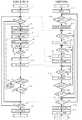
免疫分析装置1による分析処理の全体のフローを図に示す。なお、以下のフローチャート中の判断において、「Yes」及び「No」を図示しない場合は、下がYes、右(左)がNoである。また、以下に説明する処理は、制御部400a及び本体制御部140によって制御される処理である。
[Whole process]
The overall flow of the analysis process by theimmune analyzer 1 is shown in the figure. In addition, in the determination in the following flowchart, when “Yes” and “No” are not illustrated, the bottom is Yes and the right (left) is No. Further, the process described below is a process controlled by thecontrol unit 400a and the mainbody control unit 140.

まず、免疫分析装置1の電源が投入されると、本体制御部140の初期化が行われる(ステップS1)。この初期化動作では、プログラムの初期化や免疫分析装置1の駆動部分の原位置復帰等が行われる。
一方、免疫分析装置1に通信可能に接続されたパーソナルコンピュータ401の電源が投入されると、当該パーソナルコンピュータ401の制御部400aの初期化が行われる(ステップS101)。この初期化動作では、プログラムの初期化等が行われる。
First, when the power supply of theimmune analyzer 1 is turned on, the mainbody control unit 140 is initialized (step S1). In this initialization operation, initialization of the program, return to the original position of the driving portion of theimmune analyzer 1, and the like are performed.
On the other hand, when thepersonal computer 401 communicably connected to theimmune analyzer 1 is turned on, thecontrol unit 400a of thepersonal computer 401 is initialized (step S101). In this initialization operation, initialization of the program and the like are performed.

ついでステップS102において、制御部400aによって、測定開始の指示が行われたか否かが判断される。制御部400aは、測定開始の指示が行われたと判断した場合(Yes)にはステップS103へ処理を進め、測定開始の指示が行われなかったと判断した場合(No)にはステップS113へ処理を進める。そして、ステップS103において、測定開始信号が制御部400aから本体制御部140へ送信される。
ついでステップS2において、本体制御部140によって、測定開始信号の受信が行われたか否かが判断される。本体制御部140が、測定開始信号の受信が行われたと判断した場合(Yes)にはステップS3へ処理を進め、測定開始信号の受信が行われなかったと判断した場合(No)にはステップS14へ処理を進める。
In step S102, thecontrol unit 400a determines whether an instruction to start measurement has been issued. When it is determined that a measurement start instruction has been given (Yes), thecontrol unit 400a proceeds to step S103, and when it is determined that a measurement start instruction has not been given (No), the process proceeds to step S113. Proceed. In step S103, a measurement start signal is transmitted from thecontrol unit 400a to the mainbody control unit 140.
In step S2, the mainbody control unit 140 determines whether a measurement start signal has been received. If the mainbody control unit 140 determines that the measurement start signal has been received (Yes), the process proceeds to step S3. If the mainbody control unit 140 determines that the measurement start signal has not been received (No), the process proceeds to step S14. Proceed to the process.

ついでステップS3において、検体搬送部10により、検体を収容した複数の試験管3が載置されたラック4が検体分注アーム50の吸引位置1aに対応する位置まで搬送される。前記ラック4には、当該ラック4を特定するための情報(ラック番号)が記録された、記録部であるバーコードが付されており、このラック4を所定の位置まで搬送する搬送路に設けられた検出部(図示せず)によって、前記バーコードが読み取られる(ステップS4)。読み取られたラック番号は、ステップS5において、本体制御部140によってパーソナルコンピュータ401側に送信される。  Instep S 3, thesample transport unit 10 transports therack 4 on which the plurality oftest tubes 3 containing the sample are placed to a position corresponding to the suction position 1 a of thesample dispensing arm 50. Therack 4 is provided with a barcode serving as a recording unit in which information (rack number) for identifying therack 4 is recorded, and is provided in a conveyance path for conveying therack 4 to a predetermined position. The bar code is read by the detected unit (not shown) (step S4). The read rack number is transmitted to thepersonal computer 401 side by the mainbody control unit 140 in step S5.

ついでステップS104において、制御部400aによって、ラック番号の受信が行われたか否かが判断される。制御部400aが、ラック番号の受信が行われたと判断した場合(Yes)にはステップS105へ処理を進める。
ついでステップS105において、制御部400aによって、オーダページの検索が行われる。すなわち、制御部400aによって、ハードディスク401dの記憶領域に記憶されているオーダ情報から、ステップS104において受信したラック番号に係るオーダ情報が検索される。
In step S104, thecontrol unit 400a determines whether or not a rack number has been received. When thecontrol unit 400a determines that the rack number has been received (Yes), the process proceeds to step S105.
In step S105, thecontrol unit 400a searches for the order page. That is, the order information related to the rack number received in step S104 is retrieved from the order information stored in the storage area of the hard disc 401d by thecontrol unit 400a.

前記試験管3には、前記ラック4と同様に当該試験管3内の検体を特定するための情報(検体番号)が記録された、記録部であるバーコードが付されており、試験管3を載置したラック4を所定の位置まで搬送する搬送路に設けられた検出部(図示せず)によって、前記バーコードが読み取られる(ステップS6)。読み取られた検体番号は、ステップS7において、パーソナルコンピュータ401側に送信される。なお、試験管3とラック4のバーコードは、別々の検出部で読み取るようにしてもよいし、共通の検出部で読み取るようにしてもよい。  Like therack 4, thetest tube 3 is attached with a barcode serving as a recording unit in which information (specimen number) for specifying the sample in thetest tube 3 is recorded. The bar code is read by a detection unit (not shown) provided in the transport path for transporting therack 4 on which the rack is placed to a predetermined position (step S6). The read sample number is transmitted to thepersonal computer 401 side in step S7. Note that the barcodes of thetest tube 3 and therack 4 may be read by separate detection units, or may be read by a common detection unit.

ついでステップS106において、制御部400aによって、検体番号の受信が行われたか否かの判断をする。制御部400aが、検体番号の受信が行われたと判断した場合(Yes)にはステップS107へ処理を進める。
ついでステップS107において、制御部400aによって、オーダの検索が行われる。すなわち、制御部400aによって、ステップS105において検索された、特定のラック番号に係るオーダ情報から、ステップS106において受信した検体番号に係るオーダ情報が検索される。そして、ステップS108において、制御部400aによって、オーダの指示が本体制御部140へ送信される。
In step S106, thecontrol unit 400a determines whether the sample number has been received. If thecontrol unit 400a determines that the sample number has been received (Yes), the process proceeds to step S107.
In step S107, thecontroller 400a searches for orders. That is, the order information related to the sample number received in step S106 is searched by thecontrol unit 400a from the order information related to the specific rack number searched in step S105. In step S108, thecontrol unit 400a transmits an order instruction to the mainbody control unit 140.

ついでステップS8において、本体制御部140によって、オーダ指示の受信が行われたか否かが判断される。本体制御部140が、オーダ指示の受信が行われたと判断した場合(Yes)にはステップS9へ処理を進める。
ついでステップS9において、オーダされた項目についての測定が行われる。そして、測定結果が、本体制御部140によりパーソナルコンピュータ401側に送信される(ステップS10)。
In step S8, the mainbody control unit 140 determines whether an order instruction has been received. If the mainbody control unit 140 determines that the order instruction has been received (Yes), the process proceeds to step S9.
In step S9, the ordered item is measured. Then, the measurement result is transmitted to thepersonal computer 401 side by the main body control unit 140 (step S10).

ついでステップS109において、制御部400aによって、測定結果の受信が行われたか否かが判断される。制御部400aが、測定結果の受信が行われたと判断した場合(Yes)にはステップS110へ処理を進める。
ステップS110では、本体制御部140側から送信された測定結果の解析処理が行われる。すなわち、制御部400aは、送信された測定結果と、予め標準試料を用いて作成され、前記ハードディスク401dに記憶されている検量線とから、測定対象の抗原の濃度を換算し、その結果(分析結果)を記憶する。また、制御部400aは、分析結果の出力を行う。
In step S109, thecontrol unit 400a determines whether or not the measurement result has been received. If thecontrol unit 400a determines that the measurement result has been received (Yes), the process proceeds to step S110.
In step S110, an analysis process of the measurement result transmitted from the mainbody control unit 140 side is performed. That is, thecontrol unit 400a converts the concentration of the antigen to be measured from the transmitted measurement result and a calibration curve which is created in advance using a standard sample and stored in the hard disc 401d, and the result (analysis) Result). Further, thecontrol unit 400a outputs an analysis result.

ついでステップS111において、制御部400aによって、ラック4に保持されているすべての試験管3中の検体について測定が行われたか否かが判断される。制御部400aは、ラック4に保持されているすべての試験管3中の検体について測定が行われたと判断した場合(Yes)にはステップS112へ処理を進め、ラック4に保持されているすべての試験管3中の検体については測定が行われていないと判断した場合(No)にはステップS106へ処理を戻す。  In step S111, thecontrol unit 400a determines whether or not the measurement has been performed on the samples in all thetest tubes 3 held in therack 4. When thecontrol unit 400a determines that the measurement has been performed on the samples in all thetest tubes 3 held in the rack 4 (Yes), thecontrol unit 400a advances the process to step S112, and all of the samples held in therack 4 are processed. If it is determined that the measurement is not performed on the sample in the test tube 3 (No), the process returns to step S106.

ついでステップS112において、制御部400aによって、すべてのラック4について測定が行われたか否かが判断される。制御部400aは、すべてのラック4について測定が行われたと判断した場合(Yes)にはステップS113へ処理を進め、すべてのラック4については測定が行われていないと判断した場合(No)にはステップS104へ処理を戻す。
ついでステップS113において、制御部400aによって、パーソナルコンピュータ401をシャットダウンする指示を受け付けているか否かが判断される。制御部400aは、シャットダウンする指示を受け付けていると判断した場合(Yes)にはステップS114へ処理を進め、シャットダウンする指示を受け付けていないと判断した場合(No)にはステップS102へ処理を戻す。
In step S112, thecontrol unit 400a determines whether measurement has been performed for allracks 4. When it is determined that measurement has been performed for all racks 4 (Yes), thecontrol unit 400a proceeds to step S113, and when it is determined that measurement has not been performed for all racks 4 (No). Returns the process to step S104.
In step S113, thecontrol unit 400a determines whether an instruction to shut down thepersonal computer 401 is received. When it is determined that an instruction to shut down is accepted (Yes),control unit 400a proceeds to step S114. When it is determined that an instruction to shut down is not accepted (No),control unit 400a returns the process to step S102. .

ついでステップS114において、シャットダウン信号が制御部400aから本体制御部140へ送信される。
そして、ステップS115において、制御部400aにより、パーソナルコンピュータ401のシャットダウンが行われ、処理が終了する。
In step S114, a shutdown signal is transmitted from thecontrol unit 400a to the mainbody control unit 140.
In step S115, thecontrol unit 400a shuts down thepersonal computer 401, and the process ends.

また、ステップS11において、本体制御部140によって、ラック4に保持されているすべての試験管3中の検体について測定が行われたか否かが判断される。本体制御部140は、ラック4に保持されているすべての試験管3中の検体について測定が行われたと判断した場合(Yes)にはステップS13へ処理を進め、ラック4に保持されているすべての試験管3中の検体については測定が行われていないと判断した場合(No)には、ラック4を所定距離(次に測定される検体を収容する試験管が被吸引位置に到達する距離)だけ搬送し(ステップS12)、ステップS6へ処理を戻す。  In step S <b> 11, the mainbody control unit 140 determines whether or not measurement has been performed on the samples in all thetest tubes 3 held in therack 4. When the mainbody control unit 140 determines that the measurement has been performed on the samples in all thetest tubes 3 held in the rack 4 (Yes), the process proceeds to step S <b> 13 and all of the samples held in therack 4. When it is determined that no measurement is performed on the sample in the test tube 3 (No), therack 4 is moved a predetermined distance (the distance at which the test tube containing the sample to be measured next reaches the aspirated position). ) Only (step S12), and the process returns to step S6.

ついでステップS13において、本体制御部140によって、すべてのラック4について測定が行われたか否かが判断される。本体制御部140は、すべてのラック4について測定が行われたと判断した場合(Yes)にはステップS14へ処理を進め、すべてのラック4については測定が行われていないと判断した場合(No)にはステップS3へ処理を戻す。
ついでステップS14において、本体制御部140によって、シャットダウン信号の受信が行われたか否かが判断される。本体制御部140が、シャットダウン信号の受信が行われたと判断した場合(Yes)にはステップS15へ処理を進め、シャットダウン信号の受信が行われていないと判断した場合(Yes)にはステップS2へ処理を戻す。
In step S13, the mainbody control unit 140 determines whether measurement has been performed for allracks 4. When the mainbody control unit 140 determines that measurement has been performed for all the racks 4 (Yes), themain control unit 140 proceeds to step S14, and determines that measurement has not been performed for all the racks 4 (No). The process returns to step S3.
In step S14, the mainbody control unit 140 determines whether a shutdown signal has been received. If the mainbody control unit 140 determines that the shutdown signal has been received (Yes), the process proceeds to step S15. If the mainbody control unit 140 determines that the shutdown signal has not been received (Yes), the process proceeds to step S2. Return processing.

そして、ステップS15において、本体制御部140により、免疫分析装置1のシャットダウンが行われ、処理が終了する。  In step S15, thebody control unit 140 shuts down theimmune analyzer 1, and the process ends.

[動作状態チェック処理]
次に、動作状態チェック処理について説明する。
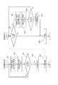
図5は、免疫分析装置1の動作状態チェック処理の手順を示すフローチャートである。検体搬送部10や検体分注アーム50、試薬分注アーム90a〜90c等の測定ユニット2を構成する各機構(コンポーネント)には、各機構の動作状況を監視するセンサ(検知手段)が設けられている。本体制御部140は、ステップS301において、各センサから検出結果を取得する。また、本体制御部140は、ステップS302において、各センサから取得した検出結果(動作状態情報)を解析する。エラーが発生している場合には、この動作状態の解析処理によってエラーが検出される。次に、ステップS303において、本体制御部140はエラーが検出されたか否かを判定する。エラーが検出されていない場合には、ステップS301へ処理が戻される。ステップS303においてエラーが検出されたと判定された場合には、ステップS304においてエラー情報が読み出される。このエラー情報は、そのエラーを特定する情報(エラーID)である。そして、本体制御部140は、ステップS305において、エラー情報を制御部400aに送信し、処理を終了する。
[Operation status check processing]
Next, the operation state check process will be described.
FIG. 5 is a flowchart showing the procedure of the operation state check process of theimmune analyzer 1. Each mechanism (component) constituting themeasurement unit 2 such as thesample transport unit 10, thesample dispensing arm 50, and thereagent dispensing arms 90 a to 90 c is provided with a sensor (detection unit) that monitors the operation status of each mechanism. ing. In step S301, the mainbody control unit 140 acquires a detection result from each sensor. In step S302, the mainbody control unit 140 analyzes the detection result (operation state information) acquired from each sensor. If an error has occurred, the error is detected by the analysis processing of this operation state. Next, in step S303, the mainbody control unit 140 determines whether an error has been detected. If no error is detected, the process returns to step S301. If it is determined in step S303 that an error has been detected, error information is read in step S304. This error information is information (error ID) that identifies the error. In step S305, the mainbody control unit 140 transmits error information to thecontrol unit 400a, and ends the process.

一方、制御部400aは、ステップS401において、エラー情報を受信したか否かを判定する。エラー情報が受信された場合には、ステップS406へ処理が進み、後述するエラー処理が実行される。一方、エラー情報が受信されていない場合には、制御部400aは、ステップS402において、制御装置400の動作状態情報を取得する。この動作状態情報には、ソフトウェアの内部状態情報や、通信インタフェース等のハードウェアの状態情報が含まれている。そして、制御部400aは、ステップS403において、取得した動作状態情報を解析する。エラーが発生している場合には、この動作状態の解析処理によってエラーが検出される。次に、ステップS404において、制御部400aはエラーが検出されたか否かを判定する。エラーが検出されていない場合には、ステップS401へ処理が戻される。ステップS404においてエラーが検出されたと判定された場合には、ステップS405においてエラー情報が読み出される。そして、制御部400aは、次に説明するエラー処理を実行し(ステップS406)、その後処理を終了する。  On the other hand, thecontrol unit 400a determines whether or not error information has been received in step S401. If error information has been received, the process proceeds to step S406, and an error process to be described later is executed. On the other hand, when the error information is not received, thecontrol unit 400a acquires the operation state information of thecontrol device 400 in step S402. This operating state information includes software internal state information and hardware state information such as a communication interface. In step S403, thecontrol unit 400a analyzes the acquired operation state information. If an error has occurred, the error is detected by the analysis processing of this operation state. Next, in step S404, thecontrol unit 400a determines whether an error has been detected. If no error is detected, the process returns to step S401. If it is determined in step S404 that an error has been detected, error information is read in step S405. Then, thecontrol unit 400a executes an error process described below (step S406), and thereafter ends the process.

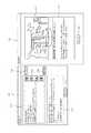
このエラー処理は、図7に示すように、表示部400bに表示されたメインウィンドウ201の装置状態表示エリア202に所定の表示を行うとともに、測定部ヘルプウィンドウ(エラーウィンドウ)210を新たに表示部400bに表示することにより行われる。  As shown in FIG. 7, in this error processing, predetermined display is performed in the apparatusstatus display area 202 of themain window 201 displayed on thedisplay unit 400b, and a measurement unit help window (error window) 210 is newly displayed on the display unit. This is done by displaying on 400b.

なお、メインウィンドウ201は、測定ユニット2を制御するためのアプリケーションプログラムを起動することによって表示部400bに表示されるウィンドウであり、タイトルバー201a、メニューバー201b、ツールバー201c、主表示区画201d、補助表示区画201eを有する。図7に示す例では、主表示区画201cにオーダ登録画面が表示されている。補助表示区画201dには、装置状態表示エリア202、メッセージ表示エリア203、消耗品情報表示エリア204が設けられている。測定部ヘルプウィンドウ210は、メインウィンドウ201の主表示区画201cに、先に表示されている画面上に重ねて表示される。  Themain window 201 is a window displayed on thedisplay unit 400b by starting an application program for controlling themeasurement unit 2, and includes a title bar 201a, amenu bar 201b, a toolbar 201c, a main display section 201d, an auxiliary display It has adisplay section 201e. In the example shown in FIG. 7, an order registration screen is displayed in the main display section 201c. In the auxiliary display section 201d, an apparatusstatus display area 202, amessage display area 203, and a consumableinformation display area 204 are provided. The measurementunit help window 210 is displayed in the main display section 201c of themain window 201 so as to overlap the previously displayed screen.

制御部400aのハードディスク401dには、装置で起こり得る様々なエラーの態様について情報が予め記憶されている。具体的には、エラー名称(エラーの簡単な内容)、エラー発生箇所、エラーの復旧方法等の情報が互いに関連づけられた状態で記憶されている。また、エラー発生箇所についての情報は、当該箇所を3次元的又は2次元的に表現した画像(図面、写真、絵)による情報を含んでいる。  The hard disk 401d of thecontrol unit 400a stores in advance information on various error modes that can occur in the apparatus. Specifically, information such as an error name (simple contents of an error), an error occurrence location, and an error recovery method is stored in a state of being associated with each other. Further, the information on the location where the error has occurred includes information based on an image (drawing, photograph, picture) that represents the location in a three-dimensional or two-dimensional manner.

図6は、制御部400aによるエラー処理の手順を示すフローチャートである。
図6のステップS411において、制御部400aは、検出されたエラーに対応するエラー名称、アクションメッセージ、及びエラー復帰用アイコンをハードディスク401dから読み出す処理を行う。ここで、アクションメッセージとは、主としてエラーの復旧方法に関する情報であって、エラーを復旧するための手順を文章(テキスト)で表したものである。エラー復帰用アイコン220は、同じくエラーの復旧方法に関する情報であって、図7に示すように、当該エラーから復帰するためにユーザーが行うべき動作を簡略的に図示したものである。
FIG. 6 is a flowchart showing a procedure of error processing by thecontrol unit 400a.
In step S411 in FIG. 6, thecontrol unit 400a performs a process of reading an error name, an action message, and an error recovery icon corresponding to the detected error from the hard disk 401d. Here, the action message is mainly information related to an error recovery method, and represents a procedure for recovering an error in text (text). Theerror recovery icon 220 is also information related to an error recovery method, and simply shows an operation to be performed by the user in order to recover from the error, as shown in FIG.

図6のステップS412において、制御部400aは、検出されたエラーに対応する表示色で装置状態表示エリア202を表示し(図7に点線のハッチングで示す;表示色の詳細については後述する)、当該エラーに対応するエラー復帰用アイコン220がある場合は、そのエラー復帰用アイコン220を装置状態表示エリア202に表示する。さらに、図7に示すような測定部ヘルプウィンドウ210をメインウィンドウ201上に表示する(ステップS413)。また、測定部ヘルプウィンドウ210の表示とともにアラーム音を発生させる。  In step S412 of FIG. 6, thecontrol unit 400a displays the devicestatus display area 202 in a display color corresponding to the detected error (shown by dotted hatching in FIG. 7; details of the display color will be described later). If there is anerror recovery icon 220 corresponding to the error, theerror recovery icon 220 is displayed in the apparatusstatus display area 202. Further, a measurementunit help window 210 as shown in FIG. 7 is displayed on the main window 201 (step S413). In addition, an alarm sound is generated together with the display of the measurementunit help window 210.

この測定部ヘルプウィンドウ210の上部側にはエラーリスト(エラー名称表示エリア)210aが設けられ、このエラーリスト210aには、検出された1又は複数のエラー名称が表示される。図7に示す例では、エラーリスト210aに7個のエラー名称が上下に羅列して表示されている。このエラーリスト210aには優先順位の高い順番でエラー名称が表示される。エラーリスト210a内の右側には、エラー名称をスクロールさせるボタン210bが設けられている。また、測定部ヘルプウィンドウ210の下部側にはアクション表示エリア(復旧操作表示エリア)210cが設けられ、このアクション表示エリア210cには、エラーリスト210aで選択されたエラー名称に対応するアクションメッセージが表示される。  An error list (error name display area) 210a is provided on the upper side of the measurementunit help window 210, and one or more detected error names are displayed in the error list 210a. In the example shown in FIG. 7, seven error names are displayed in the error list 210a in an up-and-down direction. In this error list 210a, error names are displayed in order of priority. On the right side of the error list 210a, a button 210b for scrolling the error name is provided. In addition, an action display area (recovery operation display area) 210c is provided on the lower side of the measurementunit help window 210, and an action message corresponding to the error name selected in the error list 210a is displayed in this action display area 210c. Is done.

測定部ヘルプウィンドウ210が立ち上がった直後の初期状態ではエラーリスト210a内の最上部のエラー名称が選択された状態になり、そのエラー名称に対応したアクションメッセージがアクション表示エリア210cに表示される。ユーザーが他のエラー名称を選択すると、そのエラー名称に対応したアクションメッセージがアクション表示エリア210cに表示される。
このような処理を行うため、制御部400aは、図6のステップS414において、エラーリスト210a内の他のエラー名称の選択を受け付けたか否かを判断する。制御部400aは、エラーリスト210a内の他のエラー名称の選択を受け付けた場合(Yes)、ステップS415へ処理を進め、当該選択を受け付けなかった場合(No)にはステップS416へ処理を進める。ステップS415において、制御部400aは、新たに選択されたエラー名称に対応するアクションメッセージをアクション表示エリア210cに表示する。
In the initial state immediately after the measurementunit help window 210 is launched, the top error name in the error list 210a is selected, and an action message corresponding to the error name is displayed in the action display area 210c. When the user selects another error name, an action message corresponding to the error name is displayed in the action display area 210c.
In order to perform such processing, thecontrol unit 400a determines whether or not selection of another error name in the error list 210a is accepted in step S414 of FIG. When the selection of another error name in the error list 210a is accepted (Yes), thecontrol unit 400a advances the process to Step S415, and when the selection is not accepted (No), thecontrol unit 400a advances the process to Step S416. In step S415, thecontrol unit 400a displays an action message corresponding to the newly selected error name in the action display area 210c.

ユーザーは、測定部ヘルプウィンドウ210に表示されたエラー名称とアクションメッセージを読み、アクションメッセージに表示された手順で操作を行うことによってエラーを復旧することが可能となる。また、アラームリセットボタン210dを選択することによってアラーム音を停止することができる。  The user can recover the error by reading the error name and the action message displayed in the measurementunit help window 210 and performing an operation according to the procedure displayed in the action message. Also, the alarm sound can be stopped by selecting the alarm reset button 210d.

図7に示すように、装置状態表示エリア202には、「エラー」という文字が表示されるとともに、2つのエラー復帰用アイコン220a,220bが表示されている。一方のエラー復帰用アイコン220aは、ラック4の再セットを指示する「ラック再セットアイコン」であり、他方のエラー復帰用アイコン220bは、メインウィンドウ201の右上に表示された測定開始ボタン204の選択を指示する「測定開始アイコン」である。  As shown in FIG. 7, in the apparatusstatus display area 202, characters “error” are displayed and two error recovery icons 220a and 220b are displayed. One error recovery icon 220 a is a “rack reset icon” that instructs to reset therack 4, and the other error recovery icon 220 b is a selection of themeasurement start button 204 displayed on the upper right of themain window 201. Is a “measurement start icon”.

装置状態表示エリア202にこのようなラック再セットアイコン220aや測定開始アイコン220bが表示された場合、ユーザーは、検体搬送部10に対してラック4を再セットするとともに、メインウィンドウ201の測定開始ボタン204を選択(クリック)することによって、測定を再開することが可能となる。すなわち、装置状態表示エリア202に画像表示されたエラー復帰用アイコン220に従ってユーザーが操作することにより、エラー状態から復旧することが可能となっている。  When such a rack reset icon 220a or a measurement start icon 220b is displayed in the apparatusstatus display area 202, the user resets therack 4 with respect to thesample transport unit 10 and also starts a measurement start button on themain window 201. By selecting (clicking) 204, the measurement can be resumed. That is, it is possible to recover from the error state by the user operating according to theerror recovery icon 220 displayed as an image in the apparatusstate display area 202.

エラー復帰用アイコン220は、その画像のデザインによってユーザーが行うべき操作内容を認識できるように構成されている。例えば、ラック再セットアイコン220aは、ラック4を模写した簡略的な画像とラック4の再セットを表す矢印とから構成され、ユーザーはこの画像のデザインを見て行うべき操作を連想することが可能である。また、測定開始アイコン220bは、測定開始ボタン204と同じデザインとされており、これによってユーザーは、測定開始アイコン220bと同じ画像のボタンを探して選択すればよく、別のボタンを誤って選択してしまうような誤操作を防止することができる。  Theerror recovery icon 220 is configured to recognize the operation content to be performed by the user based on the design of the image. For example, the rack reset icon 220a is composed of a simple image obtained by copying therack 4 and an arrow indicating the reset of therack 4, and the user can associate the operation to be performed by looking at the design of the image. It is. In addition, the measurement start icon 220b has the same design as themeasurement start button 204, which allows the user to search for and select a button with the same image as the measurement start icon 220b, and to select another button by mistake. It is possible to prevent such erroneous operation.

制御部400aは、エラー処理に関する動作として、測定部ヘルプウィンドウ210に加えて異常箇所ダイアログ230(図8参照)の表示を行うことができる。この異常箇所ダイアログ230は、図7に示すように、測定部ヘルプウィンドウ210内の「異常箇所」ボタン210eを選択(クリック)することによって新たに立ち上がるウィンドウであり、ユーザーが測定部ヘルプウィンドウ210に表示された内容だけではエラー箇所を認識することができない場合や、そのエラーについての詳細な情報を知りたい場合に、必要に応じて表示させることができるものである。  Thecontrol part 400a can display the abnormal part dialog 230 (refer FIG. 8) in addition to the measurementpart help window 210 as operation | movement regarding an error process. As shown in FIG. 7, theabnormal location dialog 230 is a window that is newly launched by selecting (clicking) the “abnormal location” button 210 e in the measurementunit help window 210, and the user enters the measurementunit help window 210. If the error location cannot be recognized only by the displayed content, or if it is desired to know detailed information about the error, it can be displayed as necessary.

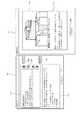
図8は、図7で示したものとは異なる内容の測定部ヘルプウィンドウ210と、この測定部ヘルプウィンドウ210に対応する異常箇所ダイアログ230を示す図である。この図8に示す例では、測定部ヘルプウィンド210のエラーリストには「ホストコンピュータ通信異常」というエラー名称が選択され、そのアクションメッセージとして、アクション表示エリア210cには、「ホストコンピュータとの接続設定をOFFにしています。ホストコンピュータに問題がない場合は、設定をONにしてください。」という復旧情報が表示されている。  FIG. 8 is a diagram showing a measurementunit help window 210 having a content different from that shown in FIG. 7 and anabnormal part dialog 230 corresponding to the measurementunit help window 210. In the example shown in FIG. 8, the error name “host computer communication error” is selected in the error list of the measurementunit help window 210, and the action message is displayed in the action display area 210 c as “Connection setting with host computer”. "If there is no problem with the host computer, please turn the setting on." Is displayed.

そして、ユーザーがこの測定部ヘルプウィンドウ210aの異常箇所ボタン210eを選択すると、その右側に示すような異常箇所ダイアログ230が立ち上がる。この異常箇所ダイアログ230の上部側には、エラー発生箇所を画像で表示するエラー箇所表示エリア230aが設けられている。エラー箇所表示エリア230aには、制御装置400(IPU)と、この制御装置400に通信可能に接続されたホストコンピュータ(HOST)との関係が3次元画像で表示されている。異常箇所ダイアログ230の下部側には、エラーの発生原因等のエラーに関する詳細内容を表示する詳細内容表示エリア230bが設けられている。このような異常箇所画像が表示されることにより、ユーザーは制御装置400でエラーが発生していることを視覚的に認識することができる。  When the user selects the abnormal part button 210e in the measurement unit help window 210a, anabnormal part dialog 230 as shown on the right side of the measurement part help window 210a is launched. An errorlocation display area 230 a for displaying an error occurrence location as an image is provided on the upper side of theabnormal location dialog 230. In the errorlocation display area 230a, a relationship between the control device 400 (IPU) and a host computer (HOST) connected to thecontrol device 400 so as to be communicable is displayed as a three-dimensional image. On the lower side of theabnormal part dialog 230, a detailed content display area 230b for displaying the detailed content regarding the error such as the cause of the error is provided. By displaying such an abnormal part image, the user can visually recognize that an error has occurred in thecontrol device 400.

このような異常箇所ダイアログ230の表示を行うため、制御部400aは、図6のステップS416において、測定部ヘルプウィンドウ210の異常箇所ボタン210eがユーザーによって選択された否か、すなわち、異常箇所ダイアログ210eの表示指示を受け付けたか否かを判断する。異常箇所ダイアログ230の表示指示を受け付けた場合(Yes)、制御部400aはステップS417へ処理を進め、当該表示指示を受け付けなかった場合(No)はステップS421へ処理を進める。  In order to display such anabnormal location dialog 230, thecontrol unit 400a determines whether or not the abnormal location button 210e of the measurementunit help window 210 is selected by the user in step S416 of FIG. 6, that is, the abnormal location dialog 210e. It is determined whether or not a display instruction is accepted. When the display instruction of theabnormal part dialog 230 is received (Yes), thecontrol unit 400a advances the process to Step S417, and when the display instruction is not received (No), thecontrol part 400a advances the process to Step S421.

ステップS417において、制御部400aは、エラーリスト210aで選択されたエラー名称に対応する異常箇所画像及びエラー詳細メッセージをハードディスク401dから読み出し、ステップS418において異常箇所ダイアログ230を表示する。
ユーザーは、異常箇所ダイアログ230のエラー箇所表示エリア230aに表示された異常箇所画像からエラーが発生した箇所を視覚的に認識することができる。すなわち、測定部ヘルプウィンドウ210のアクションメッセージだけではエラー発生箇所が解り難い場合に、異常箇所ダイアログ230を表示させることで、操作経験の浅いユーザーであってもエラー発生箇所を正確に認識し、復旧させることが可能となる。また、詳細内容表示エリア230bに表示されたエラー詳細メッセージを読むことによってユーザーはエラーについてのより詳しい情報を得ることができる。
なお、測定部ヘルプウィンドウ210の表示内容だけでエラーの復旧が可能な場合には、ユーザーは、必ずしも異常箇所ダイアログ230を表示させなくてもよい。
In step S417, thecontrol unit 400a reads the abnormal part image and the error detail message corresponding to the error name selected in the error list 210a from the hard disc 401d, and displays theabnormal part dialog 230 in step S418.
The user can visually recognize the location where the error has occurred from the abnormal location image displayed in the errorlocation display area 230a of theabnormal location dialog 230. That is, when it is difficult to understand the error location by only the action message in the measurementunit help window 210, theerror location dialog 230 is displayed so that even a user with little experience can accurately recognize and restore the error location. It becomes possible to make it. Further, the user can obtain more detailed information about the error by reading the error detail message displayed in the detailed content display area 230b.
If the error can be recovered only by the display contents of the measurementunit help window 210, the user does not necessarily have to display theabnormal part dialog 230.

図9は、他の例に係る測定部ヘルプウィンドウ210と、この測定部ヘルプウィンドウ210に対応する異常箇所ダイアログ230を示す図である。この図9に示す例では、測定部ヘルプウィンド210のエラーリスト210aには「検体吸引センサ異常」というエラー名称が選択され、そのアクションメッセージとして、エラーに伴う測定ユニット2の動作内容、エラーの復旧手順が文章表示されている。さらに、ユーザーが異常箇所ボタン210eを選択すると異常箇所ダイアログ230が表示され、そのエラー箇所表示エリア230aには、検体吸引部位(検体分注アーム50)を中心とするその周囲の3次元画像が表示され、詳細内容表示エリア230bには、エラーの原因やエラーが復旧しなかった場合の対処法等が表示されている。エラー箇所表示エリア230aでは、エラー箇所に対してその部分が目立つような色(赤色等;ハッチングで示す)が付される。  FIG. 9 is a diagram showing a measurementunit help window 210 according to another example and anabnormal part dialog 230 corresponding to the measurementunit help window 210. In the example shown in FIG. 9, an error name “specimen aspiration sensor abnormality” is selected in the error list 210a of the measurementunit help window 210, and the action contents of themeasurement unit 2 associated with the error and error recovery are taken as the action message. The procedure is displayed in text. Further, when the user selects the abnormal part button 210e, anabnormal part dialog 230 is displayed, and the errorpart display area 230a displays a three-dimensional image around the specimen aspirating part (specimen dispensing arm 50). In the detailed content display area 230b, the cause of the error and a countermeasure when the error is not recovered are displayed. In the errorlocation display area 230a, a color (red or the like; indicated by hatching) that makes the portion conspicuous is attached to the error location.

図10は、さらに他の例に係る測定部ヘルプウィンドウ210と、この測定部ヘルプウィンドウ210に対応する異常箇所ダイアログ230を示す図である。この図10に示す例では、測定部ヘルプウィンドウ210のエラーリスト210aで「操作カバーが開いています」というエラー名称が選択され、そのアクションメッセージとして、エラーに伴う測定ユニット2の動作内容、エラーの復旧手順が文章で表示されている。さらに、ユーザーが異常箇所ボタン210eを選択すると、異常箇所ダイアログ230が表示され、そのエラー箇所表示エリア230aには、測定部ユニット2の操作カバーを中心とするその周囲の3次元画像が表示され、詳細内容表示エリア230bには、エラー原因やエラーが復旧しなかった場合の対処法等が表示されている。エラー箇所表示エリア230aでは、エラーが発生した箇所に対してその部分が目立つような色(ハッチングで示す)が付される。  FIG. 10 is a diagram showing a measurementunit help window 210 according to still another example and anabnormal part dialog 230 corresponding to the measurementunit help window 210. In the example shown in FIG. 10, the error name “Operation cover is open” is selected in the error list 210a of the measurementunit help window 210, and the action message of themeasurement unit 2 associated with the error and the error The recovery procedure is displayed in text. Further, when the user selects the abnormal part button 210e, anabnormal part dialog 230 is displayed, and in the errorpart display area 230a, a three-dimensional image around the operation cover of the measuringunit 2 is displayed. In the detailed content display area 230b, the cause of the error and a countermeasure when the error is not recovered are displayed. In the errorlocation display area 230a, a color (indicated by hatching) is attached to a location where an error has occurred to make the portion conspicuous.

ユーザーがエラーを復旧した後、異常箇所ダイアログ230を閉じる場合は、同ダイアログ230の「閉じる」ボタン230cを選択する。この際、制御部400aは、図6のステップS419において、ユーザーが異常箇所ダイアログの「閉じる」ボタン230cを選択したか否か、つまり異常箇所ダイアログ230の非表示指示を受け付けた否かを判断する。当該非表示指示を受け付けた場合(Yes)、制御部400aはステップS420へ処理を進め、異常箇所ダイアログ230を非表示にする(閉じる)処理を行う。  When theerror location dialog 230 is closed after the user recovers the error, the “close”button 230 c of thedialog 230 is selected. At this time, thecontrol unit 400a determines in step S419 in FIG. 6 whether or not the user has selected the “close”button 230c of the abnormal part dialog, that is, whether or not an instruction to hide theabnormal part dialog 230 has been accepted. . When the non-display instruction is received (Yes), thecontrol unit 400a advances the process to step S420, and performs a process of hiding (closing) theabnormal part dialog 230.

ついで制御部400aは、ステップS421において、エラー復旧に必要な操作(処理)が行われたか否かを判断し、当該操作が行われた場合(Yes)はステップS422へ処理を進め、行われなかった場合にはステップS414へ処理を戻す。ステップS422において、制御部400aは、復旧されたエラー名称を測定部ヘルプウィンドウ210のエラーリスト210aから削除する。さらに、ステップS423において、制御部400aは、必要に応じて装置状態表示エリア202(図7参照)の表示色を切り換え、対応するエラー復旧用アイコン220を非表示にし、処理をステップS414に戻す。  Next, in step S421, thecontrol unit 400a determines whether or not an operation (process) necessary for error recovery has been performed. If the operation has been performed (Yes), the process proceeds to step S422 and is not performed. If YES, the process returns to step S414. In step S422, thecontrol unit 400a deletes the recovered error name from the error list 210a of the measurementunit help window 210. Furthermore, in step S423, thecontrol unit 400a switches the display color of the apparatus status display area 202 (see FIG. 7) as necessary, hides the correspondingerror recovery icon 220, and returns the process to step S414.

[装置状態表示エリア]
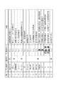
図11は、図7に示した装置状態表示エリア202のテキスト表示、表示色、エラー復帰用アイコン、及び装置状態の関係を対応づけて説明するテーブルである。メインウィンドウ201の装置状態表示エリア202には測定ユニット2の装置状態を表す文字情報(テキスト)が表示され、装置状態に応じて当該エリア202全体の色が灰、青、緑、黄、又は赤に切り換えられる。本実施の形態では、図11のNo.1〜No.15に示す各装置状態に応じて、装置状態表示エリア202に表示するテキストデータ、各表示色の装置状態表示エリア202の背景画像、及びエラー復帰用アイコンが予め設定されており、それぞれを対応づけて制御部400aのハードディスク401dに記憶させている。
[Device status display area]
FIG. 11 is a table for explaining the relationship among the text display, display color, error recovery icon, and device status in the devicestatus display area 202 shown in FIG. Character information (text) representing the device status of themeasurement unit 2 is displayed in the devicestatus display area 202 of themain window 201, and the color of theentire area 202 is gray, blue, green, yellow, or red depending on the device status. Can be switched to. In this embodiment, No. 1 in FIG. 1-No. 15, text data to be displayed in the devicestatus display area 202, a background image of the devicestatus display area 202 for each display color, and an error recovery icon are set in advance and correspond to each other. And stored in the hard disk 401d of thecontrol unit 400a.

装置状態表示エリア202の色は、例えば、測定ユニット2の電源がオフ状態にあり測定ができない場合には「灰」とされ(No.1)、測定ユニット2の電源がオンであるが、すぐに測定を行うことができない状態(休止状態、スリープ状態等)では「青」とされ(No.2,3)、測定ユニット2は測定動作を行っていないが、すぐに又は間もなく測定を開始できる状態では「緑」とされ(No.4〜No.6)、測定ユニット2が測定動作、初期動作、保守動作等を行っている状態では「黄」とされる(No.7〜No.14)。また、測定中等に致命的なエラーが生じて測定できなくなった場合には「赤」とされる(No.15)。これらの各表示色の装置画像表示エリア202の背景画像がそれぞれの装置状態と対応づけられてハードディスク401dに記憶されている。  The color of the devicestatus display area 202 is, for example, “gray” when themeasurement unit 2 is turned off and measurement is not possible (No. 1), and themeasurement unit 2 is turned on immediately. In a state where measurement cannot be performed (pause state, sleep state, etc.), it is “blue” (No. 2, 3), and themeasurement unit 2 is not performing a measurement operation, but can start measurement immediately or soon. In the state, it is “green” (No. 4 to No. 6), and in the state where themeasurement unit 2 is performing measurement operation, initial operation, maintenance operation, etc., it is “yellow” (No. 7 to No. 14). ). In addition, when a fatal error occurs during measurement or the like and measurement cannot be performed, “red” is set (No. 15). The background image of the deviceimage display area 202 of each display color is stored in the hard disc 401d in association with each device state.

本実施の形態では、測定ユニット2の動作中(表示色が「黄」)に、何らかのエラーが発生した場合に、上述したエラー復帰用アイコン220(図7参照)を装置状態表示エリア202に表示する。例えば、測定ユニット2の動作中に中断ボタン205(図7参照)が押されると、既に吸引された検体が測定中のままで新たな検体の吸引が停止される。この場合、図11のNo.11に示すように、装置状態表示エリア202には黄色の背景画像が表示され、「中断中」とテキスト表示されるとともに、エラー復帰用アイコン220として「測定開始アイコン」220bが表示される。ユーザーは、当該エラーが生じた場合には、測定開始アイコン220bに従って測定開始ボタン204(図7参照)を選択することにより測定を再開することができる。  In the present embodiment, when any error occurs during the operation of the measurement unit 2 (display color is “yellow”), the above-described error recovery icon 220 (see FIG. 7) is displayed in the apparatusstatus display area 202. To do. For example, when the interruption button 205 (see FIG. 7) is pressed during the operation of themeasurement unit 2, the aspiration of a new sample is stopped while the already aspirated sample is still being measured. In this case, no. As shown in FIG. 11, a yellow background image is displayed in the apparatusstatus display area 202, “suspending” is displayed as text, and a “measurement start icon” 220 b is displayed as theerror recovery icon 220. When the error occurs, the user can restart the measurement by selecting the measurement start button 204 (see FIG. 7) according to the measurement start icon 220b.

また、本実施の形態では、図11のNo.12〜No.14に示すように、測定ユニット2の動作中(表示色が「黄」)に「エラー」とテキスト表示されるパターンが3つある。いずれも既に吸引された検体は測定中であるが、新たな検体の吸引を停止した状態となるエラーであり、No.12は、単に測定開始ボタン204を選択することによって測定再開が可能なエラー、No.13は、ラック4を再セットし且つ測定開始ボタン204を選択することによって測定再開が可能なエラー、No.14は、ラック4を再セットした後、現在の測定が終了するまで測定再開ができないエラー(測定開始ボタン204の選択を受け付けないエラー)である。  In this embodiment, No. 1 in FIG. 12-No. As shown in FIG. 14, there are three patterns in which “error” is displayed as text during the operation of the measurement unit 2 (display color is “yellow”). In both cases, the aspirated specimen is being measured, but this is an error in which aspiration of a new specimen is stopped. No. 12 is an error in which measurement can be resumed by simply selecting themeasurement start button 204, No. 12 No. 13 is an error in which measurement can be resumed by resetting therack 4 and selecting themeasurement start button 204, No. 13Reference numeral 14 denotes an error in which the measurement cannot be resumed after therack 4 is reset until the current measurement is completed (an error that does not accept selection of the measurement start button 204).

No.12では、測定開始ボタン204を選択するだけで測定再開可能であるので、装置状態表示エリア202には「測定開始アイコン」220bのみが表示され、No.13では、ラック再セット後に測定開始ボタン204を選択すれば測定再開可能であるので、「ラック再セットアイコン」220aと「測定開始アイコン」220bとの両方が表示される。No.14では、ラック4の再セットが必要であるが、測定開始ボタン204を選択できないので、「ラック再セットアイコン」220aと、「測定開始不可アイコン」(測定開始アイコンに×印をつけたもの)が表示されるようになっている。  No. 12, since the measurement can be resumed only by selecting themeasurement start button 204, only the “measurement start icon” 220 b is displayed in the apparatusstatus display area 202. 13, since the measurement can be resumed by selecting themeasurement start button 204 after the rack is reset, both the “rack reset icon” 220a and the “measurement start icon” 220b are displayed. No. 14, it is necessary to reset therack 4, but themeasurement start button 204 cannot be selected. Therefore, a “rack reset icon” 220 a and a “measurement start impossible icon” (measurement start icon marked with an X) Is displayed.

以上のように、装置状態表示エリア202には、測定ユニット2の装置状態に応じた色が付されるので、ユーザーは測定ユニット2が動作可能かどうか、既に動いているかどうか等の状態を一見して認識することが可能となっている。  As described above, the devicestatus display area 202 is colored according to the device status of themeasurement unit 2, so that the user can see the status of whether themeasurement unit 2 is operable, whether it is already moving, etc. Can be recognized.

本発明は、上記実施の形態に限定されることなく適宜設計変更可能である。例えば、異常箇所ダイアログ230は、測定部ヘルプウィンドウ210と同時に表示部400aに表示させることもできるし、これらを1つのウィンドウとして表示させることもできる。本発明は、免疫分析装置に限らず、血液凝固測定装置、多項目血球分析装置、尿中有形成分分析装置、遺伝子増幅測定装置等の他の分析装置にも適用可能である。  The present invention is not limited to the embodiment described above, and can be appropriately changed in design. For example, theabnormal part dialog 230 can be displayed on thedisplay unit 400a simultaneously with the measurementunit help window 210, or can be displayed as one window. The present invention is not limited to an immune analyzer, but can be applied to other analyzers such as a blood coagulation measuring device, a multi-item blood cell analyzer, a urine sediment analyzer, and a gene amplification measuring device.

1 免疫分析装置
140 本体制御部
210 測定部ヘルプウィンドウ
220 エラー復帰用アイコン
230 異常箇所ダイアログ
400 制御装置
400a 制御部
400b 表示部
400c 入力部
DESCRIPTION OFSYMBOLS 1Immune analyzer 140 Mainbody control part 210 Measuringpart help window 220Error recovery icon 230Abnormal part dialog 400Control apparatus 400aControl part400b Display part 400c Input part

Claims (9)

Translated fromJapanese
ラックを搬送する検体搬送部と、A sample transport section for transporting the rack;
前記検体搬送部によって搬送されたラック上の検体を吸引して測定を行う測定部と、A measurement unit that performs measurement by sucking the sample on the rack transported by the sample transport unit;
表示部と、A display unit;
前記表示部に、装置の状態を表示する装置状態表示エリアおよび測定開始を指示するための測定開始ボタンを含むメインウィンドウを表示させる表示制御手段と、を備え、Display control means for displaying a main window including an apparatus state display area for displaying the state of the apparatus and a measurement start button for instructing measurement start on the display unit,
エラーの発生によってラックの搬送および新たな検体の吸引が停止した場合、前記表示制御手段は、When the transport of the rack and the suction of a new sample are stopped due to the occurrence of an error, the display control means
前記エラーが、ラックを再セットすることなくラックの搬送および検体吸引を再開可能なエラーである場合には、前記測定開始ボタンの操作を促す情報を前記装置状態表示エリアに表示させ、When the error is an error that can restart rack transport and sample aspiration without resetting the rack, information for prompting the operation of the measurement start button is displayed in the apparatus status display area,
前記エラーが、ラックを再セットすることによりラックの搬送および検体吸引を再開可能なエラーである場合には、ラックの再セットを促す情報と、前記測定開始ボタンの操作を促す情報を、前記装置状態表示エリアに表示させる、検体分析装置。If the error is an error that can restart rack transport and sample aspiration by resetting the rack, information that prompts the user to reset the rack and information that prompts the user to operate the measurement start button Sample analyzer that displays in the status display area.
前記測定部は、エラーの発生によってラックの搬送および新たな検体の吸引が停止した場合、エラー発生時に既に吸引した検体の測定を継続することが可能であり、The measurement unit can continue measurement of a sample that has already been aspirated when an error occurs, when rack transport and aspiration of a new sample stop due to the occurrence of an error,
前記表示制御手段は、前記エラーが、既に吸引された検体の測定が終了するまで、ラックの搬送および検体吸引を再開できないエラーである場合、前記測定開始ボタンが操作できないことを示唆する情報を前記装置状態表示エリアに表示させる、請求項1の検体分析装置。If the error is an error in which rack transport and sample aspiration cannot be resumed until the measurement of the already aspirated sample is completed, the display control means displays information indicating that the measurement start button cannot be operated. 2. The sample analyzer according to claim 1, wherein the sample analyzer is displayed in an apparatus status display area.
前記ラックの再セットを促す情報が、ラックを示す画像を含む、請求項1または2に記載の検体分析装置。  The sample analyzer according to claim 1, wherein the information that prompts the user to reset the rack includes an image indicating the rack. 前記測定開始ボタンの操作を促す情報が、前記測定開始ボタンを示す画像を含む、請求項1〜3のいずれか一項に記載の検体分析装置。  The sample analyzer according to any one of claims 1 to 3, wherein the information prompting the operation of the measurement start button includes an image indicating the measurement start button.前記表示制御手段は、前記装置の状態に応じて、前記装置状態表示エリアの表示色を切り換えるように構成されている、請求項1〜4のいずれか一項に記載の検体分析装置。The sample analyzer according to any one of claims 1 to 4, wherein the display control unit is configured to switch a display color of the device status display area according to a status of the device.前記表示制御手段は、The display control means includes
前記エラーが、ラックを再セットし、又はラックを再セットすることなく、ラックの搬送および検体吸引を再開可能なエラーである場合には、前記装置状態表示エリアを第1の表示色で表示させ、If the error is an error that can restart rack transportation and sample aspiration without resetting the rack or resetting the rack, the apparatus status display area is displayed in the first display color. ,
前記エラーが、ラックの搬送および検体吸引が再開できないエラーである場合には、前記装置状態表示エリアを第2の表示色で表示させる、請求項5に記載の検体分析装置。6. The sample analyzer according to claim 5, wherein when the error is an error in which rack transportation and sample aspiration cannot be resumed, the apparatus status display area is displayed in a second display color.
前記表示制御手段は、エラーが発生しておらず、且つ、測定開始ボタンを操作することによって、ラックの搬送および検体吸引を開始できる状態にある場合には、前記装置状態表示エリアを第3の表示色で表示させる、請求項6に記載の検体分析装置。  The display control means displays the apparatus status display area in the third state when no error has occurred and when the transport of the rack and the sample aspiration can be started by operating the measurement start button. The sample analyzer according to claim 6, wherein the sample analyzer displays the display color.前記表示制御手段は、エラーの発生によって、ラックの搬送および検体吸引が停止した場合、前記エラーを復旧するための復旧情報を含むヘルプウィンドウを、前記メインウィンドウの上に、前記測定開始ボタンおよび前記装置状態表示エリアに重ならないように表示させる、請求項1〜7のいずれか一項に記載の検体分析装置。When the rack transport and sample aspiration are stopped due to the occurrence of an error, the display control means displays a help window including recovery information for recovering the error on the main window, the measurement start button and the The sample analyzer according to any one of claims 1 to 7, wherein the sample analyzer is displayed so as not to overlap the apparatus state display area.前記エラーが、ラックを再セットすることによりラックの搬送および検体吸引を再開可能なエラーである場合、前記復旧情報は、ラックの再セットを促すメッセージを含む、請求項8に記載の検体分析装置。9. The sample analyzer according to claim 8, wherein when the error is an error that can restart rack transportation and sample aspiration by resetting the rack, the recovery information includes a message that prompts the user to reset the rack. .
JP2012096129A2012-04-202012-04-20 Sample analyzerActiveJP5331916B2 (en)

Priority Applications (1)

Application NumberPriority DateFiling DateTitle
JP2012096129AJP5331916B2 (en)2012-04-202012-04-20 Sample analyzer

Applications Claiming Priority (1)

Application NumberPriority DateFiling DateTitle
JP2012096129AJP5331916B2 (en)2012-04-202012-04-20 Sample analyzer

Related Parent Applications (1)

Application NumberTitlePriority DateFiling Date
JP2007243428ADivisionJP5089307B2 (en)2007-09-202007-09-20 Sample analyzer

Publications (2)

Publication NumberPublication Date
JP2012163567Atrue JP2012163567A (en)2012-08-30
JP5331916B2 JP5331916B2 (en)2013-10-30

Family

ID=46843065

Family Applications (1)

Application NumberTitlePriority DateFiling Date
JP2012096129AActiveJP5331916B2 (en)2012-04-202012-04-20 Sample analyzer

Country Status (1)

CountryLink
JP (1)JP5331916B2 (en)

Cited By (7)

* Cited by examiner, † Cited by third party
Publication numberPriority datePublication dateAssigneeTitle
JP2015049249A (en)*2013-09-042015-03-16エフ ホフマン−ラ ロッシュ アクチェン ゲゼルシャフトMethod for processing biological sample and analysis system
JP2018112531A (en)*2017-01-132018-07-19キヤノン株式会社Measurement device, method for measurement, and program
EP3428652A2 (en)2017-07-142019-01-16Horiba, Ltd.Specimen analysis apparatus
CN109856048A (en)*2017-11-302019-06-07希森美康株式会社Sample measures method and sample measures device
US12007403B2 (en)2013-03-152024-06-11Abbott LaboratoriesAutomated diagnostic analyzers having rear accessible track systems and related methods
JP2024103555A (en)*2021-06-302024-08-01株式会社デンソー Equipment Status Monitoring System
WO2025037494A1 (en)*2023-08-142025-02-20株式会社日立ハイテクAutomatic analysis device and automatic analysis method

Citations (6)

* Cited by examiner, † Cited by third party
Publication numberPriority datePublication dateAssigneeTitle
JPH06118108A (en)*1992-10-061994-04-28Matsushita Electric Ind Co Ltd Electronic component mounter failure diagnosis method
JP2002116212A (en)*2001-08-162002-04-19Horiba LtdAnalyzer and display device for analyzer
JP2003232797A (en)*2001-12-052003-08-22Sysmex CorpBiological sample analyzer
JP2004028932A (en)*2002-06-282004-01-29Hitachi High-Technologies Corp Automatic analyzer
JP2005037132A (en)*2003-07-152005-02-10Sysmex CorpAnalyzing system
JP2006284380A (en)*2005-03-312006-10-19Sysmex CorpAnalyzer

Patent Citations (6)

* Cited by examiner, † Cited by third party
Publication numberPriority datePublication dateAssigneeTitle
JPH06118108A (en)*1992-10-061994-04-28Matsushita Electric Ind Co Ltd Electronic component mounter failure diagnosis method
JP2002116212A (en)*2001-08-162002-04-19Horiba LtdAnalyzer and display device for analyzer
JP2003232797A (en)*2001-12-052003-08-22Sysmex CorpBiological sample analyzer
JP2004028932A (en)*2002-06-282004-01-29Hitachi High-Technologies Corp Automatic analyzer
JP2005037132A (en)*2003-07-152005-02-10Sysmex CorpAnalyzing system
JP2006284380A (en)*2005-03-312006-10-19Sysmex CorpAnalyzer

Cited By (10)

* Cited by examiner, † Cited by third party
Publication numberPriority datePublication dateAssigneeTitle
US12007403B2 (en)2013-03-152024-06-11Abbott LaboratoriesAutomated diagnostic analyzers having rear accessible track systems and related methods
JP2015049249A (en)*2013-09-042015-03-16エフ ホフマン−ラ ロッシュ アクチェン ゲゼルシャフトMethod for processing biological sample and analysis system
JP2018112531A (en)*2017-01-132018-07-19キヤノン株式会社Measurement device, method for measurement, and program
EP3428652A2 (en)2017-07-142019-01-16Horiba, Ltd.Specimen analysis apparatus
CN109254161A (en)*2017-07-142019-01-22株式会社堀场制作所Sample analyzer
US11087876B2 (en)2017-07-142021-08-10Horiba, Ltd.Specimen analysis apparatus
CN109856048A (en)*2017-11-302019-06-07希森美康株式会社Sample measures method and sample measures device
CN109856048B (en)*2017-11-302022-11-04希森美康株式会社Sample measuring method and sample measuring apparatus
JP2024103555A (en)*2021-06-302024-08-01株式会社デンソー Equipment Status Monitoring System
WO2025037494A1 (en)*2023-08-142025-02-20株式会社日立ハイテクAutomatic analysis device and automatic analysis method

Also Published As

Publication numberPublication date
JP5331916B2 (en)2013-10-30

Similar Documents

PublicationPublication DateTitle
JP5089307B2 (en) Sample analyzer
JP5170737B2 (en) Sample analyzer
JP5331916B2 (en) Sample analyzer
JP5179890B2 (en) Sample analyzer
JP4969292B2 (en) Sample analyzer
JP5377866B2 (en) Sample analyzer
JP5486160B2 (en) Sample analyzer, abnormality control method thereof, and program for sample analyzer
JP5386099B2 (en) Analyzing apparatus and method for restarting measurement from abnormality
JP5143630B2 (en) Analysis equipment
US8071029B2 (en)Sample analyzer and sample analyzing method
US8425839B2 (en)Sample analyzer
JP5670129B2 (en) Sample processing apparatus and sample processing method
JP2007333466A (en)Analyzer
JP2009074901A (en) Sample analyzer
JP2009244177A (en)Analyzer, analysis method, and computer program
EP2682754A1 (en)Position adjustment method for movable unit in specimen analysis device, and specimen analysis device
JP7329625B2 (en) Automatic analyzer, display system for automatic analyzer, and display method for automatic analyzer
JP5108366B2 (en) Sample analyzer
JP5722406B2 (en) Sample analyzer
WO2019021645A1 (en)Automated analyzer and image processing method
JP7358999B2 (en) automatic analyzer
JP2015010961A (en)Analyzer and analysis method
JP2022160062A (en) automatic analyzer

Legal Events

DateCodeTitleDescription
TRDDDecision of grant or rejection written
A01Written decision to grant a patent or to grant a registration (utility model)

Free format text:JAPANESE INTERMEDIATE CODE: A01

Effective date:20130702

A61First payment of annual fees (during grant procedure)

Free format text:JAPANESE INTERMEDIATE CODE: A61

Effective date:20130729

R150Certificate of patent or registration of utility model

Ref document number:5331916

Country of ref document:JP

Free format text:JAPANESE INTERMEDIATE CODE: R150

Free format text:JAPANESE INTERMEDIATE CODE: R150

R250Receipt of annual fees

Free format text:JAPANESE INTERMEDIATE CODE: R250

R250Receipt of annual fees

Free format text:JAPANESE INTERMEDIATE CODE: R250

R250Receipt of annual fees

Free format text:JAPANESE INTERMEDIATE CODE: R250

R250Receipt of annual fees

Free format text:JAPANESE INTERMEDIATE CODE: R250

R250Receipt of annual fees

Free format text:JAPANESE INTERMEDIATE CODE: R250


[8]ページ先頭

©2009-2025 Movatter.jp