JP2012160224A - Objective lens, optical pickup device using the same, and manufacturing method for objective lens - Google Patents
Objective lens, optical pickup device using the same, and manufacturing method for objective lensDownload PDFInfo
- Publication number
- JP2012160224A JP2012160224AJP2011017835AJP2011017835AJP2012160224AJP 2012160224 AJP2012160224 AJP 2012160224AJP 2011017835 AJP2011017835 AJP 2011017835AJP 2011017835 AJP2011017835 AJP 2011017835AJP 2012160224 AJP2012160224 AJP 2012160224A
- Authority
- JP
- Japan
- Prior art keywords
- objective lens
- laser beam
- annular zone
- region
- standard
- Prior art date
- Legal status (The legal status is an assumption and is not a legal conclusion. Google has not performed a legal analysis and makes no representation as to the accuracy of the status listed.)
- Pending
Links
- 230000003287optical effectEffects0.000titleclaimsabstractdescription95
- 238000004519manufacturing processMethods0.000titleclaimsdescription22
- 230000004075alterationEffects0.000claimsdescription51
- 239000011347resinSubstances0.000claimsdescription26
- 229920005989resinPolymers0.000claimsdescription26
- 239000000463materialSubstances0.000claimsdescription21
- 230000015572biosynthetic processEffects0.000claimsdescription20
- 238000000034methodMethods0.000claimsdescription6
- 230000002093peripheral effectEffects0.000claimsdescription4
- 239000007788liquidSubstances0.000claimsdescription3
- 239000007787solidSubstances0.000claimsdescription2
- 239000010410layerSubstances0.000description37
- 230000010287polarizationEffects0.000description14
- 238000001746injection mouldingMethods0.000description10
- 230000000694effectsEffects0.000description7
- 238000001514detection methodMethods0.000description6
- 239000011521glassSubstances0.000description6
- 230000000630rising effectEffects0.000description6
- 239000000853adhesiveSubstances0.000description5
- 230000001070adhesive effectEffects0.000description5
- 230000005540biological transmissionEffects0.000description5
- 239000011247coating layerSubstances0.000description5
- 229920000089Cyclic olefin copolymerPolymers0.000description4
- 239000004417polycarbonateSubstances0.000description4
- 201000009310astigmatismDiseases0.000description3
- 238000006243chemical reactionMethods0.000description3
- NJPPVKZQTLUDBO-UHFFFAOYSA-NnovaluronChemical compoundC1=C(Cl)C(OC(F)(F)C(OC(F)(F)F)F)=CC=C1NC(=O)NC(=O)C1=C(F)C=CC=C1FNJPPVKZQTLUDBO-UHFFFAOYSA-N0.000description3
- 230000008569processEffects0.000description3
- 238000003786synthesis reactionMethods0.000description3
- 239000004925Acrylic resinSubstances0.000description2
- 229920000178Acrylic resinPolymers0.000description2
- 239000004713Cyclic olefin copolymerSubstances0.000description2
- 230000008901benefitEffects0.000description2
- 239000011229interlayerSubstances0.000description2
- 238000000465mouldingMethods0.000description2
- 239000004033plasticSubstances0.000description2
- 229920003023plasticPolymers0.000description2
- 229920003229poly(methyl methacrylate)Polymers0.000description2
- 229920000515polycarbonatePolymers0.000description2
- 239000004926polymethyl methacrylateSubstances0.000description2
- 229920005672polyolefin resinPolymers0.000description2
- 235000005811Viola aduncaNutrition0.000description1
- 240000009038Viola odorataSpecies0.000description1
- 235000013487Viola odorataNutrition0.000description1
- 235000002254Viola papilionaceaNutrition0.000description1
- 230000001154acute effectEffects0.000description1
- 230000006378damageEffects0.000description1
- 230000001747exhibiting effectEffects0.000description1
- 230000009477glass transitionEffects0.000description1
- 230000012447hatchingEffects0.000description1
- 238000010438heat treatmentMethods0.000description1
- 238000002347injectionMethods0.000description1
- 239000007924injectionSubstances0.000description1
- 239000002184metalSubstances0.000description1
- 230000010363phase shiftEffects0.000description1
- 230000001737promoting effectEffects0.000description1
- 238000002310reflectometryMethods0.000description1
- 238000000926separation methodMethods0.000description1
- 230000002194synthesizing effectEffects0.000description1
- 230000009466transformationEffects0.000description1
Images


Classifications
- G—PHYSICS
- G11—INFORMATION STORAGE
- G11B—INFORMATION STORAGE BASED ON RELATIVE MOVEMENT BETWEEN RECORD CARRIER AND TRANSDUCER
- G11B7/00—Recording or reproducing by optical means, e.g. recording using a thermal beam of optical radiation by modifying optical properties or the physical structure, reproducing using an optical beam at lower power by sensing optical properties; Record carriers therefor
- G11B7/12—Heads, e.g. forming of the optical beam spot or modulation of the optical beam
- G11B7/135—Means for guiding the beam from the source to the record carrier or from the record carrier to the detector
- G11B7/1372—Lenses
- G11B7/1374—Objective lenses
- G—PHYSICS
- G11—INFORMATION STORAGE
- G11B—INFORMATION STORAGE BASED ON RELATIVE MOVEMENT BETWEEN RECORD CARRIER AND TRANSDUCER
- G11B7/00—Recording or reproducing by optical means, e.g. recording using a thermal beam of optical radiation by modifying optical properties or the physical structure, reproducing using an optical beam at lower power by sensing optical properties; Record carriers therefor
- G11B7/12—Heads, e.g. forming of the optical beam spot or modulation of the optical beam
- G11B7/135—Means for guiding the beam from the source to the record carrier or from the record carrier to the detector
- G11B7/1365—Separate or integrated refractive elements, e.g. wave plates
- G11B7/1367—Stepped phase plates
- G—PHYSICS
- G11—INFORMATION STORAGE
- G11B—INFORMATION STORAGE BASED ON RELATIVE MOVEMENT BETWEEN RECORD CARRIER AND TRANSDUCER
- G11B7/00—Recording or reproducing by optical means, e.g. recording using a thermal beam of optical radiation by modifying optical properties or the physical structure, reproducing using an optical beam at lower power by sensing optical properties; Record carriers therefor
- G11B7/12—Heads, e.g. forming of the optical beam spot or modulation of the optical beam
- G11B7/135—Means for guiding the beam from the source to the record carrier or from the record carrier to the detector
- G11B7/1392—Means for controlling the beam wavefront, e.g. for correction of aberration
- G11B7/13922—Means for controlling the beam wavefront, e.g. for correction of aberration passive
- G—PHYSICS
- G11—INFORMATION STORAGE
- G11B—INFORMATION STORAGE BASED ON RELATIVE MOVEMENT BETWEEN RECORD CARRIER AND TRANSDUCER
- G11B7/00—Recording or reproducing by optical means, e.g. recording using a thermal beam of optical radiation by modifying optical properties or the physical structure, reproducing using an optical beam at lower power by sensing optical properties; Record carriers therefor
- G11B2007/0003—Recording, reproducing or erasing systems characterised by the structure or type of the carrier
- G11B2007/0006—Recording, reproducing or erasing systems characterised by the structure or type of the carrier adapted for scanning different types of carrier, e.g. CD & DVD
Landscapes
- Physics & Mathematics (AREA)
- Optics & Photonics (AREA)
- Optical Head (AREA)
- Lenses (AREA)
Abstract
Description
Translated fromJapanese本発明は、成形性が向上された対物レンズおよびそれを用いた光ピックアップ装置に関する。さらに本発明は、この様な対物レンズの製造方法に関する。 The present invention relates to an objective lens with improved moldability and an optical pickup device using the objective lens. Furthermore, the present invention relates to a method for manufacturing such an objective lens.
従来から、光ディスクの読出し及び書込には、ガラスまたはプラスチック材料を金型で所定に成形した対物レンズが用いられている。 Conventionally, an objective lens in which a glass or plastic material is molded in a predetermined mold with a mold is used for reading and writing of an optical disk.
特許文献1に開示されたプラスチック材料からなる対物レンズの製造方法では、図2およびその説明箇所等を参照すると、金型部11および金型部12から成る金型を用意し、この金型の内部に樹脂材料を注入することにより、所定形状を備えた対物レンズを成形している。ここで、金型部11および金型部12の内壁の形状は、成形される対物レンズのレンズ面形状に即した形状を備えている。 In the method for manufacturing an objective lens made of a plastic material disclosed in
一方、光ピックアップ装置に必要とされる部品点数を削減するために、複数の規格のレンズ面を対応する光ディスクに集光する互換レンズが開発されている。例えば、BD(Blu−ray Disc)規格、DVD(Digital Versatile Disc)規格およびCD(Compact Disc)規格のレーザー光を、対応する規格の光ディスクに集光する互換対物レンズが開発されている。 On the other hand, in order to reduce the number of parts required for the optical pickup device, a compatible lens for condensing a plurality of standard lens surfaces on a corresponding optical disk has been developed. For example, compatible objective lenses that focus laser light of the BD (Blu-ray Disc) standard, DVD (Digital Versatile Disc) standard, and CD (Compact Disc) standard on an optical disc of a corresponding standard have been developed.
しかしながら、上記した金型を用いた対物レンズの製造方法では射出成形が容易でない問題があった。 However, the objective lens manufacturing method using the mold described above has a problem that injection molding is not easy.
具体的には、互換対物レンズのレンズ面には、光ディスクの情報記録層を被覆する被覆層の厚みに関連して発生する球面収差を補正するために、輪帯段差が設けられている。従って、この様な輪帯段差を備える互換対物レンズを射出成形で成形するためには、金型の内壁に、対物レンズの輪帯段差の形状に即した段差部を設ける必要がある。しかしながら、段差量が大きい段差部を金型の内壁に設けると、金型の内部で樹脂材料等を硬化させる際の硬化収縮により、射出成形された対物レンズの輪帯段差と、金型の段差部が過度に嵌合してしまう。このようになると、対物レンズを金型から離型させることが困難になる問題があった。更に、上記した硬化収縮量の度合いが大きいと、金型の段差部に嵌合した対物レンズの輪帯段差が変形あるいは破損してしまい、対物レンズの光学的特性が劣化する恐れもある。 Specifically, an annular step is provided on the lens surface of the compatible objective lens in order to correct spherical aberration that occurs in relation to the thickness of the coating layer that covers the information recording layer of the optical disc. Therefore, in order to form an interchangeable objective lens having such an annular zone step by injection molding, it is necessary to provide a step portion corresponding to the shape of the annular zone step of the objective lens on the inner wall of the mold. However, if a step portion with a large step amount is provided on the inner wall of the mold, the annular step of the injection-molded objective lens and the step of the mold are caused by curing shrinkage when the resin material is cured inside the mold. The part will fit too much. In this case, there is a problem that it is difficult to release the objective lens from the mold. Furthermore, if the degree of curing shrinkage is large, the annular step of the objective lens fitted to the step portion of the mold may be deformed or damaged, and the optical characteristics of the objective lens may be deteriorated.
更にまた、対物レンズの搬送工程や取付工程等において、対物レンズの外側に配置される輪帯段差は、内側に配置される輪帯段差よりも衝撃等が作用やすい条件にある。従って、対物レンズの外側に段差量が大きい輪帯段差を配置すると、衝撃等の外力が対物レンズに作用した場合、輪帯段差に発生する変形量も大きくなり、対物レンズの特性が大きく劣化してしまう恐れがある。 Furthermore, in an objective lens transporting process, an attaching process, and the like, the annular zone step disposed on the outside of the objective lens is in a condition where an impact or the like is more likely to act than the annular zone step disposed on the inside. Therefore, if an annular zone step with a large step amount is arranged outside the objective lens, when an external force such as an impact is applied to the objective lens, the amount of deformation generated in the annular zone step increases, and the characteristics of the objective lens are greatly degraded. There is a risk that.
本発明は上記した問題を鑑みてなされたものである。本発明の目的は、金型を用いて好適に製造することを可能とする対物レンズおよびそれを備えた光ピックアップ装置を提供することにある。さらに本発明の目的は、このような対物レンズの製造方法を提供することにある。 The present invention has been made in view of the above problems. An object of the present invention is to provide an objective lens that can be preferably manufactured using a mold and an optical pickup device including the objective lens. Furthermore, the objective of this invention is providing the manufacturing method of such an objective lens.
本発明は、第1波長を有する第1レーザー光を第1光ディスクの情報記録層に集光させ、前記第1波長よりも長い第2波長を有する第2レーザー光を、第2光ディスクの情報記録層に集光させ、前記両レーザー光よりも長い第3波長を有する第3レーザー光を、第3光ディスクの情報記録層に集光させる、対物レンズであり、前記対物レンズの中央部付近に配置された領域であり、前記第1レーザー光、前記第2レーザー光および前記第3レーザー光の何れか複数を、対応する光ディスクの前記情報記録層に集光し、第1輪帯段差が設けられた第1共用領域と、前記第1共用領域よりも外側に配置された領域であり、前記第1レーザー光、前記第2レーザー光および前記第3レーザー光の何れか複数を、対応する光ディスクの前記情報記録層に集光し、第2輪帯段差が設けられた第2共用領域と、を備え、前記第1共用領域に設けられる第1輪帯段差の段差量が、前記第2共用領域に設けられる第2輪帯段差の段差量よりも大きいことを特徴とする。 According to the present invention, a first laser beam having a first wavelength is condensed on an information recording layer of a first optical disc, and a second laser beam having a second wavelength longer than the first wavelength is recorded on the information recording layer of the second optical disc. An objective lens that focuses light on a layer and focuses third laser light having a third wavelength longer than both laser lights on an information recording layer of a third optical disk, and is disposed near the center of the objective lens A plurality of the first laser beam, the second laser beam, and the third laser beam are focused on the information recording layer of the corresponding optical disc, and a first annular step is provided. A first shared region and a region arranged outside the first shared region, and any one of the first laser beam, the second laser beam, and the third laser beam is transmitted to a corresponding optical disc. The information recording layer And a second shared area provided with a second annular zone step, and a step amount of the first annular zone provided in the first shared region is provided in the second shared region. It is characterized by being larger than the step amount of the annular zone step.
本発明の光ピックアップ装置は、この様な構成の対物レンズを備えたものである。 The optical pickup device of the present invention includes the objective lens having such a configuration.
本発明は、互いに対向する第1レンズ面と第2レンズ面とを備え、前記第1レンズ面に複数の輪帯段差を備えた対物レンズを製造する対物レンズの製造方法であり、前記第1レンズ面に対応した形状の内壁を備えた第1金型と、前記第2レンズ面に対応した形状の内壁を備えた第2金型とを当接させてキャビティを構成し、前記キャビティの内部で前記対物レンズの材料を硬化させる工程と、前記第1金型と前記第2金型とを離型させて対物レンズを取り出す工程と、を備え、前記第1金型の前記内壁は、前記対物レンズの前記第1レンズ面に設けられる複数の輪帯段差に対応した段差部を有し、前記第1金型の内壁で内側に配置される前記段差部の段差量を、前記第1金型の内壁で外側に設けられる前記段差部の段差量よりも大きくすることを特徴とする。 The present invention is a method of manufacturing an objective lens that includes a first lens surface and a second lens surface facing each other, and that manufactures an objective lens having a plurality of annular zone steps on the first lens surface. A cavity is formed by contacting a first mold having an inner wall having a shape corresponding to the lens surface and a second mold having an inner wall having a shape corresponding to the second lens surface. Curing the material of the objective lens, and releasing the objective lens by releasing the first mold and the second mold, and the inner wall of the first mold includes the A step portion corresponding to a plurality of annular zone steps provided on the first lens surface of the objective lens, and a step amount of the step portion arranged on the inner side of the inner wall of the first mold is set to the first mold. It should be larger than the level difference of the level difference provided on the outside of the inner wall of the mold. The features.
本発明では、波長が異なる複数のレーザー光を集光する共用領域を複数個有し、中央付近の第1共用領域に設けられる第1輪帯段差の段差量を、外側に配置される第2共用領域に設けられる第2輪帯段差の段差量よりも大きくしている。このようにすることで、金型を用いて射出成形の際に発生する収縮量は外側よりも内側の領域の方が小さいので、大きな段差量を備えた第1輪帯段差に作用する応力が小さくなり、第1輪帯段差の変形や破壊が防止される。 In the present invention, there are a plurality of shared areas for condensing a plurality of laser beams having different wavelengths, and the step amount of the first annular zone step provided in the first shared area near the center is arranged outside the second step. It is larger than the step amount of the second annular zone step provided in the common area. By doing so, the amount of shrinkage that occurs during injection molding using a mold is smaller in the inner region than in the outer portion, so that the stress acting on the first annular zone step having a large step amount is reduced. It becomes small and the deformation | transformation and destruction of a 1st ring zone level | step difference are prevented.
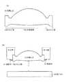
図1を参照して、本形態に係る対物レンズ10を説明する。図1(A)は対物レンズ10を全体的に示す断面図であり、図1(B)は対物レンズ10に形成される各領域の特性を示す表であり、(C)から(E)は輪帯段差の形状を示す断面図である。 With reference to FIG. 1, the
対物レンズ10は、第1レンズ面10Aと第2レンズ面10Bとを備えており、使用状況下に於いては第1レンズ面10A側から第2レンズ面10Bを通過するようにレーザー光は照射される。 The
対物レンズ10の材料としては、樹脂材料またはガラスが採用される。ここで、樹脂材料としては、ポリオレフィン樹脂(環状オレフィンコポリマー、シクロオレフィンポリマー)が採用さる。また、樹脂材料としては、PMMA樹脂(アクリル樹脂)、PC樹脂(ポリカーボネート)等も採用可能である。 As the material of the
対物レンズ10は、波長の異なる複数のレーザー光を光ディスクの情報記録層に集光する。具体的には、対物レンズ10は、BD(Blu−ray Disc)規格、DVD(Digital Versatile Disc)規格およびCD(Compact Disc)規格のレーザー光を、各規格に対応する光ディスクの情報記録層に集光する。 The
ここで、BD規格のレーザー光の波長は青紫色(青色)波長帯395nm〜420nm(例えば405nm)であり、DVD規格のレーザー光の波長は赤色波長帯645nm〜675nm(例えば、655nm)であり、CD規格のレーザー光の波長は赤外波長帯765nm〜805nm(例えば785nm)である。また、対物レンズ10に入射するレーザー光は、無限光または弱有限光である。無限光は、単層の情報記録層を備える各規格の光ディスクに適用される。弱有限光のレーザー光は、多層の情報記録層を備えるBD規格またはDVD規格の光ディスクに使用される。 Here, the wavelength of the laser beam of the BD standard is a blue-violet (blue) wavelength band of 395 nm to 420 nm (for example, 405 nm), and the wavelength of the laser beam of the DVD standard is a red wavelength band of 645 nm to 675 nm (for example, 655 nm), The wavelength of the laser beam of the CD standard is an infrared wavelength band of 765 nm to 805 nm (for example, 785 nm). The laser light incident on the
図1(A)を参照して、対物レンズ10は、非球面部13Aとその周囲のフランジ部13Bから成る。非球面部13Aは、入射したレーザー光の集光に寄与する部位であり、第1レンズ面10Aと、第2レンズ面10Bとを備えている。 Referring to FIG. 1A, the
フランジ部13Bは、非球面部13Aを取り囲むように形成された部位であり、対物レンズ10を光ピックアップ装置のレンズホルダーに取り付ける際に、フランジ部13Bに接着材を塗布して固着する。この様な形状の対物レンズ10は、金型を用いた射出成形により成形され、この事項は図8を参照して後述する。ここで、フランジ部13Bの上面周辺部は、外側が下方に下がる段差形状を呈している。これにより、図8を参照して後述する射出成形により対物レンズを成形する際に、フランジ部13Bの上面が金型から離型しやすくなる。 The flange part 13B is a part formed so as to surround the
対物レンズ10の第1レンズ面10Aは、中央部付近に設けられた共用領域11Aと、この共用領域11Aを囲むように配置された輪帯状の専用領域11Bとを備えている。共用領域11Aは、BD規格、DVD規格およびCD規格のレーザー光の中の2以上を、対応する光ディスクの情報記録層に集光する。共用領域11Aは下記する第1領域F1、第2領域F2および第3領域F3とを含む。専用領域11Bは、BD規格またはDVD規格のレーザー光を、対応する光ディスクの情報記録層に集光する。専用領域11Bは、下記する第4領域F4、第5領域F5および第6領域F6を含む。 The first lens surface 10A of the
第1領域F1は、対物レンズ10の第1レンズ面10Aの中央部付近に配置された円形の領域であり、BD規格、DVD規格およびCD規格のレーザー光を、対応する光ディスクの情報記録層に集光する。また、第1領域F1は、対物レンズ10の中心から0.5928mmまでの領域に円形に形成されており、輪帯段差により区分される輪帯が形成される。ここでは、プラスの段差量を有する輪帯段差が形成されている。本形態では、輪帯段差量は対物レンズ10に入射するレーザー光の進行方向をプラスとして表している。従って、プラスの段差量を有する輪帯段差が設けられた場合、その段差の外側で対物レンズ10が薄くなる。 The first region F1 is a circular region disposed near the center of the first lens surface 10A of the
第1領域F1に形成される輪帯段差量Dは、以下の式1により算出される。 The annular zone step amount D formed in the first region F1 is calculated by the following
式1・・・・・D=m・λ/(n−1)
ここで、mは定数であり、nは対物レンズの屈折率であり、λはレーザー光の波長である。尚、実際の対物レンズ10の設計に用いられる詳細な値は図4および図5を参照して後述する。Formula 1 D = m · λ / (n−1)
Here, m is a constant, n is the refractive index of the objective lens, and λ is the wavelength of the laser light. Detailed values used for designing the actual
第1領域F1に形成される輪帯段差の段差量Dの算出に用いられる波長λとして、BD規格のレーザー光の波長(405nm)を採用している。これにより、段差の有無はBDのレーザー光の実質的な波面収差に影響を及ぼさない。一方、DVD規格のレーザー光に対しては、輪帯段差を設けることによる位相ズレは、波長の整数倍ではない。従って、第1領域F1に輪帯段差を設けることにより、DVD規格のレーザー光では色収差が発生し、この色収差により光ディスクの被覆層で発生する球面収差が補正される。これにより本形態では、DVD規格のレーザー光で発生する実質的な収差が低減されている。 As the wavelength λ used for calculating the step amount D of the annular zone step formed in the first region F1, the wavelength of the BD standard laser beam (405 nm) is employed. As a result, the presence or absence of a step does not affect the substantial wavefront aberration of the BD laser beam. On the other hand, with respect to the DVD standard laser light, the phase shift due to the annular zone step is not an integral multiple of the wavelength. Therefore, by providing an annular step in the first region F1, chromatic aberration occurs in the DVD standard laser beam, and spherical aberration generated in the coating layer of the optical disc is corrected by this chromatic aberration. Thereby, in this embodiment, substantial aberration generated by the DVD standard laser beam is reduced.
更に、図1(C)を参照して、第1領域F1に設けられる第1輪帯段差51Aの段差量E1は、他の共用領域(第2領域F2、第3領域F3)に設けられる輪帯段差よりも大きくなっている。一例として、図1(C)に示す第1領域F1の段差量E1は0.0060mm程度であり、図1(D)に示す第2領域F2に設けられる第2輪帯段差51Bの段差量E2は0.0014mm程度であり、図1(E)に示す第3領域F3に設けられる第3輪帯段差51Cの段差量E3は、0.0026mm程度である。このように、球面収差を補正するために設けられる輪帯段差の中で、最も段差量が大きいものを中心寄りに配置することにより、背景技術の欄にて述べた射出成形時の問題が回避される。この事項は図8を参照して後述する。 Further, referring to FIG. 1C, the step amount E1 of the first
更にまた、図1(C)を参照して、第1輪帯段差51Aの断面形状は、輪帯段差よりも外側の対物レンズの厚みが内側よりも薄くなるような形状である。換言すると、第1輪帯段差51A付近の対物レンズ10の形状は、所謂「なで肩」の如き形状を呈しており、鋭利に外部に向かって突出する形状ではない。このことによっても、上記した背景技術の問題が回避される。 Still further, referring to FIG. 1C, the cross-sectional shape of first
第2領域F2は、第1領域F1に隣接してその周囲を囲む輪帯状の領域(R=0.5928mm〜0.932mm)であり、DVD規格およびCD規格のレーザー光を対応する規格の光ディスクの情報記録面に集光してスポットを形成する。ここで、第2領域F2でDVD規格およびCD規格のレーザー光が集光するポイントは、第1領域F1でこれらのレーザー光が集光するポイントと同じである。即ち、各領域にてワーキングディスタンスが一致している。この事項は下記する各領域で同様である。尚、この領域に入射したBD規格のレーザー光は、スポットの形成には寄与しない。 The second region F2 is a ring-shaped region (R = 0.5928 mm to 0.932 mm) that is adjacent to and surrounds the first region F1, and is an optical disc of a standard that supports laser light of the DVD standard and CD standard. The light is condensed on the information recording surface to form a spot. Here, the point at which the laser light of the DVD standard and the CD standard is condensed in the second region F2 is the same as the point at which these laser beams are condensed in the first region F1. That is, the working distance is consistent in each area. This matter is the same in each area described below. Note that the BD standard laser light incident on this region does not contribute to spot formation.
第2領域F2にも複数の輪帯が設けられており、各輪帯同士の間に設けられる輪帯段差の段差量はDVD規格のレーザー光の波長から算出されている。これにより、色収差が発生し、この色収差によりCD規格のレーザー光に発生する球面収差が補正される。また、輪帯段差の有無は、基本的にはDVD規格のレーザー光に発生する収差には影響を及ぼさない。更に本形態では、第2領域F2を通過するBD規格のレーザー光をスポット形成に寄与させないことで、光学的超解像を実現しているが、この事項は図3(A)を参照して後述する。 A plurality of annular zones are also provided in the second region F2, and the level difference of the annular zone steps provided between the annular zones is calculated from the wavelength of the DVD laser light. Thereby, chromatic aberration is generated, and spherical aberration generated in the laser beam of the CD standard is corrected by the chromatic aberration. In addition, the presence or absence of the annular zone step basically does not affect the aberration generated in the DVD standard laser beam. Furthermore, in this embodiment, optical super-resolution is realized by not allowing the BD laser beam passing through the second region F2 to contribute to spot formation. For this matter, refer to FIG. It will be described later.
図1(D)を参照して、ここでは、第2領域F2には、マイナスの段差量を有する第2輪帯段差51Bが形成され、輪帯段差よりも外側の対物レンズが厚くなる断面形状となる。第2輪帯段差51Bの段差量がマイナスとなる理由は、CD規格のレーザー光に発生する球面収差を色収差にて補正するためである。 Referring to FIG. 1D, here, in the second area F2, a second
本形態では、第1領域F1と第2領域F2との間に輪帯段差が設けられている。これは、BD規格およびDVD規格のレーザー光で収差が最適化される第1領域F1の最外周部の位置と、DVD規格およびCD規格のレーザー光で収差が最適化される第2領域F2の最内周部との位置が合致しないからである。なお、この様な輪帯段差は、他の領域同士の間にも設けられる。また、この領域同士の間に設けられる輪帯段差に関しても、最も段差量が大きものを中心に近い位置に配置されており、これにより対物レンズを良好に射出成形することができる。 In this embodiment, an annular zone step is provided between the first region F1 and the second region F2. This is because the position of the outermost periphery of the first region F1 where the aberration is optimized by the laser beam of the BD standard and the DVD standard and the second region F2 where the aberration is optimized by the laser beam of the DVD standard and the CD standard. This is because the position with the innermost peripheral portion does not match. In addition, such an annular zone level | step difference is provided also between other area | regions. Further, the annular zone step provided between the regions is also arranged at a position close to the center of the step having the largest step amount, whereby the objective lens can be excellently injection molded.
第3領域F3は、第2領域F2に隣接してその周囲を囲む輪帯状の領域(R=0.932mm〜1.013mm)であり、BD規格およびDVD規格のレーザー光を対応する光ディスクの情報記録層に集光してスポットを形成する。第3領域F3に入射したCD規格のレーザー光はスポット形成には寄与しない。同様に、第3領域F3よりも外側の領域に入射したCD規格のレーザー光も、スポット形成には寄与しない。 The third area F3 is a ring-shaped area (R = 0.932 mm to 1.013 mm) adjacent to and surrounding the second area F2, and information on an optical disc corresponding to BD standard and DVD standard laser light. A spot is formed by focusing on the recording layer. CD standard laser light incident on the third region F3 does not contribute to spot formation. Similarly, CD standard laser light incident on a region outside the third region F3 does not contribute to spot formation.
第3領域F3には3個の輪帯が設けられており、各輪帯同士の間に形成される段差の段差量は、第1領域F1と同様に、BD規格の波長を用いて算出される。従って、この領域に於いても、輪帯段差を設けることにより発生する色収差により、DVD規格のレーザー光に発生する球面収差が補正される。 The third region F3 is provided with three annular zones, and the amount of the step formed between the annular zones is calculated using the BD standard wavelength as in the first region F1. The Accordingly, also in this region, the spherical aberration generated in the DVD standard laser beam is corrected by the chromatic aberration generated by providing the annular zone step.
図1(E)を参照して、第3領域F3に設けられる第3輪帯段差51Cの段差量E3の段差量E3は、中央付近に設けられる第1輪帯段差51Aよりも小さく成っている。また、第3輪帯段差51Cの段差量はマイナスの値であるので、その形状は第2輪帯段差51Bと同様である。 Referring to FIG. 1E, the step amount E3 of the step amount E3 of the third annular step 51C provided in the third region F3 is smaller than the first
第4領域F4は、第3領域を囲む輪帯状の領域(R=1.013mm〜1.08mm)であり、BD規格のレーザー光のみを対応する規格の光ディスクの情報記録層に集光してスポットを形成する。第4領域F4に照射されたDVD規格およびCD規格のレーザー光は、スポット形成には寄与しない。従って、BD規格以外の規格(DVD規格およびCD規格)のレーザー光で発生する球面収差を考慮する必要が無く、輪帯段差は設けられていない。このことから、第4領域F4は段差の無い連続する面形状を呈している。この事項は、特定の規格のレーザー光のみを集光する以下の第5領域F5および第6領域F6も同様である。更に、第4領域F4は、他の規格のレーザー光との兼ね合いを考慮する必要が無いので、発生する収差の量を極めて小さくすることができる。このようなBD規格のみの領域を設けることにより、対物レンズ10全体でBD規格のレーザー光に発生する収差が改善される。 The fourth region F4 is a ring-shaped region (R = 1.013 mm to 1.08 mm) surrounding the third region, and focuses only the BD standard laser beam on the information recording layer of the corresponding standard optical disc. A spot is formed. DVD standard and CD standard laser light applied to the fourth region F4 does not contribute to spot formation. Therefore, there is no need to consider spherical aberration generated by laser light of standards other than the BD standard (DVD standard and CD standard), and no annular zone step is provided. For this reason, the fourth region F4 has a continuous surface shape without a step. The same applies to the following fifth region F5 and sixth region F6 that collect only the laser beam of a specific standard. Furthermore, since it is not necessary to consider the balance with the laser beam of other standards in the fourth region F4, the amount of aberration that occurs can be made extremely small. By providing such a region only for the BD standard, the aberration generated in the laser beam of the BD standard in the entire
第5領域F5は、第4領域F4を囲む輪帯状の領域(R=1.08mm〜1.200mm)であり、DVD規格のレーザー光のみを集光してスポットを形成する。この領域に集光されたBD規格およびCD規格のレーザー光は、スポット形成には寄与しない。DVD規格のレーザー光のみを集光させる専用領域である第5領域F5を設けることにより、DVD規格のレーザー光で収差が改善される。この理由は、第4領域F4の場合と同様である。 The fifth region F5 is a ring-shaped region (R = 1.08 mm to 1.200 mm) surrounding the fourth region F4, and focuses only the DVD standard laser beam to form a spot. The BD standard and CD standard laser light focused in this region does not contribute to spot formation. By providing the fifth region F5, which is a dedicated region for condensing only the DVD standard laser beam, the aberration is improved by the DVD standard laser beam. The reason for this is the same as in the case of the fourth region F4.
第6領域F6は、第5領域F5を囲む輪帯状の領域(R=1.200mm〜1.510mm)であり、第4領域F4と同様にBD規格のレーザー光のみを集光させる領域である。対物レンズ10の最外周部に、BD規格のレーザー光を集光させる専用領域を配置することにより、BD規格のレーザー光で発生する収差が全体として更に小さくなる。 The sixth region F6 is a ring-shaped region (R = 1.200 mm to 1.510 mm) surrounding the fifth region F5, and is a region for condensing only the BD-standard laser light as in the fourth region F4. . By disposing a dedicated region for condensing BD standard laser light on the outermost periphery of the
ここで、専用領域である第4領域F4−第6領域F6には輪帯段差が設けられていないが、これらの何れかまたは複数に輪帯段差を設けても良い。この場合、設けられる輪帯段差の段差量は、上記した第1輪帯段差51Aよりも小さくする。 Here, the annular zone step is not provided in the fourth region F4 to the sixth region F6, which are dedicated regions, but an annular zone step may be provided in any or a plurality of these. In this case, the level difference of the annular zone step provided is made smaller than the first
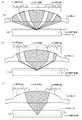
図2(A)は他の形態の対物レンズ10を示す断面図である。この図に示す対物レンズ10の構成は図1に示したものと基本的には同様であり、相違点はフランジ部13Bの形状にある。図1(A)に示した対物レンズ10では、フランジ部13Bは下方に突出する形状を呈していた。一方、この図に示す対物レンズ10では、フランジ部13Bは、下方および上方の両方に突出する形状を備えている。これにより、フランジ部13Bの上端部分の位置を変化させることにより、対物レンズが光ピックアップ装置に組み込まれた際の、対物レンズ10と光ディスクとの距離を調整できる利点がある。 FIG. 2A is a cross-sectional view showing another form of the
図2(B)を参照すると、対物レンズ10のフランジ部13Bの上面が、光ピックアップ装置の台座18に当接するように固着されている。これにより、対物レンズ10と光ディスク53との距離が決定される。 Referring to FIG. 2B, the upper surface of the flange portion 13B of the
また、対物レンズ10を固着させるための接着材21は、フランジ部13Bの側面と、台座18の下面との間に塗布されている。接着材21は、フランジ部13Bの上面と台座18の取付面との間に塗布することも可能ではあるが、そのようにすると、対物レンズ10が傾く恐れがある。本形態のように、フランジ部13Bの側面に接着材21を塗布することで、対物レンズ10が傾くことが抑制される。 The adhesive 21 for fixing the
図3を参照して、各規格のレーザー光が対物レンズ10で集光される状態を説明する。ここで、図3(A)はBD規格のレーザー光を対物レンズ10で光ディスク12Aに集光する状態を示す断面図であり、図3(B)はDVD規格に関する同様の断面図であり、図3(C)はCD規格に関する同様の断面図である。ここで、図3の各図では、スポットを形成するレーザー光が通過する部分をハッチングにて示している。一方、スポット形成には寄与しない領域にはハッチングを施していない。 With reference to FIG. 3, the state where the laser beam of each standard is condensed by the
図3(A)を参照して、上方から照射されたBD規格のレーザー光は、対物レンズ10により、BD規格の光ディスク12Aの情報記録層14Aに集光されてスポットを形成する。ここで、光ディスク12Aの情報記録層14Aを被覆する被覆層の厚さT1は、例えば0.1mmである。 Referring to FIG. 3A, the BD standard laser light irradiated from above is focused on the information recording layer 14A of the BD standard optical disk 12A by the
この図からも明らかなように、対物レンズ10に照射されるBD規格のレーザー光の全てが光ディスク12Aに集光されるのではなく、対物レンズ10に照射されたレーザー光の一部分はスポット形成に寄与しない。具体的には、対物レンズ10に照射されたレーザー光のうち、領域F1、F3、F4、F6に照射されたレーザー光が、光ディスク12Aの情報記録層14Aに集光する。一方、第2領域F2はDVD規格およびCD規格のレーザー光のみを集光するので、この領域に照射されたBD規格のレーザー光はスポット形成には寄与しない。同様に、第5領域F5はDVD規格のレーザー光のみを集光するので、この領域に照射されたBD規格のレーザー光はスポット形成に寄与しない。このように、対物レンズ10に入射したレーザー光の一部を、スポット形成に寄与させないことにより、光学的超解像を実現し、NAを規定値(BD:0.85、DVD:0.60)より小さくしても規定値のNAの場合と同等のスポット径が得られるようにして、対物レンズ10の端部の厚み(T11)を一定以上(0.274mm)に確保している。 As is clear from this figure, not all of the BD-standard laser light applied to the
尚、対物レンズ10に入射されるBD規格のレーザー光の利用効率は例えば40%程度であり、この効率であれば情報の読み出しは良好に行え、書込みについてもハイパワーのレーザーを用いれば行うことができる。 The utilization efficiency of the BD standard laser light incident on the
図3(B)を参照して、対物レンズ10に照射されたDVD規格のレーザー光が照射されると、領域F1、F2、F3およびF5に照射されたレーザー光が光ディスク12Bの情報記録層14Bに集光してスポットを形成する。一方、第4領域F4はBD規格のレーザー光のみを集光する領域であるので、この領域に照射されたDVD規格のレーザー光はスポット形成に寄与しない。同様に、BD規格のレーザー光のみを集光する第6領域F6に照射されたDVD規格のレーザー光も、スポット形成に寄与しない。このようにすることで、DVD規格のレーザー光でも光学的超解像が実現され、上記したBD規格の場合と同様の効果が得られる。 Referring to FIG. 3B, when the DVD laser light irradiated to the
尚、対物レンズ10に入射されるDVD規格のレーザー光の利用効率は例えば80%程度であり、良好に情報の読出し及び書込を行うことができる。また、DVD規格の光ディスク12Bの情報記録層14Aを被覆する被覆層の厚さT2は、0.6mmである。 The utilization efficiency of the DVD standard laser light incident on the
図3(C)を参照して、対物レンズ10にCD規格のレーザー光が照射されると、第1領域F1および第2領域F2に照射されたレーザー光のみが、光ディスク12Cの情報記録層14Cに集光してスポットを形成する。一方、領域F3、F4、F5およびF6に入射されたCD規格のレーザー光は、スポット形成に寄与しない。 Referring to FIG. 3C, when the
対物レンズ10に入射するCD規格のレーザー光の利用効率は例えば90%程度であり、問題なく情報の読出し及び書込を行うことが可能である。また、CD規格の光ディスク12Cの情報記録層14Cを被覆する被覆層の厚さT3は1.2mmである。 The utilization efficiency of CD standard laser light incident on the
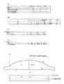
図4および図5を参照して、次に、上記した対物レンズ10の具体的な形状を説明する。図4および図5に示す表は、具現化された対物レンズの形状や特性を表す係数を示している。 Next, a specific shape of the
図4(A)および図4(B)は、BD規格、DVD規格およびCD規格の波長での、光ピックアップレンズ(対物レンズ)および、光ディスク内光透過層(被覆層)の屈折率および面間隔を示している。ここで、開口径Φ、面間隔d2、d3は、図4(E)に示す通りである。 4 (A) and 4 (B) show the refractive index and surface spacing of the optical pickup lens (objective lens) and the light transmission layer (coating layer) in the optical disc at the wavelengths of the BD standard, DVD standard and CD standard. Is shown. Here, the opening diameter Φ and the surface intervals d2 and d3 are as shown in FIG.
また、図4(C)は各規格の波長に於けるレンズ材料およびディスク内透過層の温度特性を示し、図4(D)はレンズ材料およびディスク内透過層の材料波長特性を示している。 FIG. 4C shows the temperature characteristics of the lens material and the transmission layer in the disc at each standard wavelength, and FIG. 4D shows the material wavelength characteristics of the lens material and the transmission layer in the disc.
図5に、レンズ面の形状を規定するパラメータを示す。図5(A)は、複数の輪帯が設けられるレンズ面R1(図1(A)に示す第1レンズ面10A)の形状を規定するパラメータを示す。図5(B)は対物レンズのレンズ面R2(図1(A)に示す第2レンズ面10B)の形状を示すパラメータである。 FIG. 5 shows parameters that define the shape of the lens surface. FIG. 5A shows parameters that define the shape of the lens surface R1 (the first lens surface 10A shown in FIG. 1A) on which a plurality of annular zones are provided. FIG. 5B shows parameters indicating the shape of the lens surface R2 (second lens surface 10B shown in FIG. 1A) of the objective lens.
図5(A)を参照して、この表に示された各パラメータを以下の式2に代入することでレンズ面形状が決定される。 Referring to FIG. 5A, the lens surface shape is determined by substituting each parameter shown in this table into the following

図5(A)の表では、輪帯毎に、集光するレーザー光の波長、上記式1を用いて輪帯段差量を算出する際に使用される次数mおよび波長、輪帯開始半径、輪帯終了半径および形状を算出する際に用いられる係数が示されている。ここで、輪帯1〜輪帯2が図1(A)に示す第1領域F1であり、輪帯3〜輪帯13が第2領域F2であり、輪帯14から輪帯16が第3領域F3であり、輪帯17が第4領域F4であり、輪帯18が第5領域F5であり、輪帯19が第6領域F6である。 In the table of FIG. 5 (A), for each annular zone, the wavelength of the laser beam to be collected, the order m and wavelength used when calculating the annular zone step
また、図5(B)に示す係数を以下の式3に代入することにより、レンズ面R2の形状が決定される。 Further, the shape of the lens surface R2 is determined by substituting the coefficient shown in FIG.
図6(A)を参照して、各輪帯の段差量は対物レンズの中心に対して上記式1が成立するように算出され、この後に各輪帯の面形状が最適化されている。従って、例えば、輪帯1と輪帯2との間に設けられる輪帯段差の段差量Dは、m=8、波長=405を式1に代入することで算出される。この値は輪帯2の表面を仮想延長してレンズ中心まで広げた場合の、レンズ中心部と仮想延長された面の段差量を示している。 Referring to FIG. 6 (A), the step amount of each annular zone is calculated so that the
また、図5(A)の表を参照して、輪帯3と輪帯4とを比較した場合、輪帯3の段差量Dはm=−2、波長=660を式1に代入した値であり、輪帯4の輪帯段差はm=−3、波長=660を式1に代入した値である。これらの値は、上記したように対物レンズの中心を基準とした値である。従って、両者の境界に設けられる輪帯段差の段差量は各々の値を式1に代入した段差量の差となる。 Further, referring to the table of FIG. 5A, when comparing the
更に、図5(A)では、輪帯段差の実質的な段差量(E)も示されており、図6を参照してこの詳細を説明する。 Further, FIG. 5 (A) also shows the substantial step amount (E) of the annular zone step, which will be described in detail with reference to FIG.
先ず、図5(A)の表を参照して、輪帯2の欄に示される輪帯段差量(E)の値(0.0059802mm)は、図6(A)に示すように、輪帯1と輪帯2との間に設けられる輪帯段差の段差量を示している。上記したように、本形態では、対物レンズにレーザー光が入射する方向(紙面では下方向)をプラスと規定している。従って、プラスの段差量を備えた輪帯段差が形成された場合、図に示すように、輪帯段差よりも外側の部分の対物レンズの厚みが、輪帯段差よりも内側の部分の対物レンズよりも厚みが薄くなる形状となる。 First, referring to the table of FIG. 5 (A), the value (0.0059802 mm) of the annular zone step amount (E) shown in the column of the
一方、図5(A)の表を参照して、輪帯4の欄に示される輪帯段差量(E)の値(−0.001415622mm)は、図6(B)に示すように、輪帯3と輪帯4との間に設けられる輪帯段差の段差量を示している。上記したように、輪帯段差量がマイナスの値になると、輪帯段差よりも外側の部分の対物レンズの厚さが、輪帯段差よりも内側の対物レンズの厚さよりも厚くなる形状となる。 On the other hand, referring to the table in FIG. 5A, the value (−0.001415622 mm) of the annular zone step amount (E) shown in the column of the
上記したように、輪帯段差の段差量は上記した式1を用いて算出されるが、式1に代入される定数mの値は、段差量および発生する収差を考慮して決定される。この事項を、図7の表を参照して説明する。図7(A)はBD規格の波長を基に輪帯段差量を算出した場合に各規格のレーザー光に発生する収差を示し、図7(B)はDVD規格の波長を基に輪帯段差量を算出した場合に各規格のレーザー光に発生する収差を示している。 As described above, the step amount of the annular zone step is calculated using the above-described
これらのグラフに示す残留収差を算出するための条件を説明すると、BD規格の波長は405nmであり、DVD規格の波長は660nmであり、CD規格の波長は785nmであり、BD規格の波長での対物レンズの屈折率は1.558701であり、DVD規格の波長での対物レンズの屈折率は1.539642であり、CD規格の波長での対物レンズの屈折率は1.536256である。BD規格の1波長での段差量(輪帯を中心へ仮想延長した場合の軸上段差量)は0.724895μmであり、DVDのそれは1.223003であり、CDのそれは1.463853μmである。 Explaining the conditions for calculating the residual aberration shown in these graphs, the wavelength of the BD standard is 405 nm, the wavelength of the DVD standard is 660 nm, the wavelength of the CD standard is 785 nm, and the wavelength of the BD standard is The refractive index of the objective lens is 1.558701, the refractive index of the objective lens at the DVD standard wavelength is 1.539642, and the refractive index of the objective lens at the CD standard wavelength is 1.536256. The level difference at one wavelength of the BD standard (on-axis level difference when the ring zone is virtually extended to the center) is 0.724895 μm, that of DVD is 1.223003, and that of CD is 1.4638353 μm.
また、これらのグラフでは、軸上での段差量(図6(A)に示すD)が示されているが、軸上での段差量(D)が大きいことは、輪帯段差の実際の段差量(E)が大きいことを示している。 Moreover, in these graphs, the step amount on the axis (D shown in FIG. 6A) is shown, but the large step amount (D) on the axis indicates that the actual annular zone step It shows that the level difference (E) is large.
先ず、対物レンズの中央部分に配置される第1領域F1(図1(A)参照)では、BD規格のレーザー光の波長を式1に代入して輪帯段差量が算出されている。図7(A)では、輪帯段差量が7μmを超えるまでに採用可能な次数mの値、軸上段差量、各規格のレーザー光に発生する残留収差を示している。 First, in the first region F1 (see FIG. 1A) arranged in the central portion of the objective lens, the annular zone step amount is calculated by substituting the wavelength of the laser beam of the BD standard into
ここで、先ず、第1領域F1は、BD規格、DVD規格およびCD規格のレーザー光を集光する働きを有しているので、これらの規格で発生する残留収差の値は0.3λ未満である必要である。図7(A)を参照して、この条件をみたす次数mは、2、8、10である。 Here, first, the first region F1 has a function of condensing the laser light of the BD standard, the DVD standard, and the CD standard. Therefore, the value of the residual aberration generated in these standards is less than 0.3λ. It is necessary to be. Referring to FIG. 7A, the order m satisfying this condition is 2, 8, and 10.
しかしながら、次数を10とすると輪帯段差量が大きくなりすぎ、対物レンズを射出成形により製造する際の成形性が悪化する恐れがあるので、次数mとしては2または8が適当である。 However, if the order is 10, the annular zone step amount becomes too large, and the moldability when the objective lens is manufactured by injection molding may be deteriorated. Therefore, 2 or 8 is appropriate as the order m.
更に、次数mが2の場合と8の場合とを比較すると、8の方が好適である。この理由は、次数mを8とすると、DVD規格およびCD規格で発生する残留収差がマイナスの値となり、両規格で収差が増加する割合と逆の符号となる。この結果、輪帯段差が設けられた箇所にて、残留収差により球面収差が少なる方向に補正される。一方、実数mとして2を採用すると、DVD規格では残留収差はマイナスの値となるが、CD規格ではプラスの値となってしまうので、CD規格でのレーザー光に発生する収差を補正することが困難である。 Further, when the order m is 2 and 8 is compared, 8 is preferable. This is because, when the order m is 8, the residual aberration generated in the DVD standard and the CD standard is a negative value, and the sign is opposite to the rate of increase in aberration in both standards. As a result, the spherical aberration is corrected in the direction in which the spherical aberration is reduced by the residual aberration at the portion where the annular zone step is provided. On the other hand, when 2 is adopted as the real number m, the residual aberration becomes a negative value in the DVD standard, but a positive value in the CD standard. Therefore, the aberration generated in the laser light in the CD standard can be corrected. Have difficulty.
第2領域F2は、DVD規格およびCD規格のレーザー光を集光するので、波長が短いDVD規格の波長で輪帯段差量を算出する。この結果、図7(B)に示すように各規格のレーザー光に収差が発生する。本形態では、第2領域F2の輪帯段差を算出するための次数mとして1を採用している。このようにすることで、先ず、CD規格のレーザー光に発生する収差が0.3λ未満(0.16451λ)となり、第2領域F2で良好にCD規格のレーザー光を集光することができる。更に、BD規格のレーザー光に発生する収差の値は、0.3λ以上(0.31282λ)となるので、第2領域F2に入射したレーザー光をスポット形成に寄与させないことができる。これにより、上記したように光学的超解像が実現される。 Since the second region F2 condenses the laser light of the DVD standard and the CD standard, the annular zone step amount is calculated at the wavelength of the DVD standard having a short wavelength. As a result, as shown in FIG. 7B, aberration occurs in each standard laser beam. In this embodiment, 1 is adopted as the order m for calculating the annular zone step in the second region F2. In this way, first, the aberration generated in the CD standard laser light is less than 0.3λ (0.16451λ), and the CD standard laser light can be favorably condensed in the second region F2. Furthermore, since the value of the aberration generated in the BD standard laser beam is 0.3λ or more (0.31282λ), the laser beam incident on the second region F2 can be prevented from contributing to spot formation. Thereby, as described above, optical super-resolution is realized.
第3領域F3は、BD規格およびDVD規格のレーザー光を集光するので、BD規格の波長で輪帯段差を算出し、この際の次数mとして3を採用している。このようにすれば、図7(A)を参照して、DVD規格のレーザー光に発生する収差が絶対値で0.3λ未満(0.21189λ)となる。一方、CD規格のレーザー光に発生する収差は、0.3λ以上(0.485591λ)となるので、第3領域F3に入射したCD規格のレーザー光はスポット形成に寄与しない。第3領域F3を通過するCD規格のレーザー光が、CD規格の光ディスクの情報記録層に集光してしまうと、この領域の開口数が大きいことから、スポット径が不必要に小さくなってしまう恐れがある。本形態では、第3領域F3を通過するCD規格のレーザー光に大きな収差を付与することで、この恐れを排除している。 Since the third region F3 condenses BD standard and DVD standard laser light, the annular zone step is calculated at the wavelength of the BD standard, and 3 is employed as the order m at this time. In this way, referring to FIG. 7A, the absolute value of the aberration generated in the DVD standard laser light is less than 0.3λ (0.21189λ). On the other hand, since the aberration generated in the CD standard laser beam is 0.3λ or more (0.485559λ), the CD standard laser beam incident on the third region F3 does not contribute to spot formation. When the CD standard laser beam passing through the third region F3 is condensed on the information recording layer of the CD standard optical disc, the spot diameter becomes unnecessarily small because the numerical aperture of this region is large. There is a fear. In this embodiment, this fear is eliminated by giving large aberration to the CD standard laser beam passing through the third region F3.
上記したように本形態では、集光するべきレーザー光に発生する残留収差の値を0.3λ未満とすることで読取・書出の精度を向上させているが、この値は変更可能である。例えば、より好ましい残留収差の値は0.25λ未満であり、特に好ましい値は0.20λ未満であり、このような値を採用することにより、読取・書出の精度が更に向上される。 As described above, in this embodiment, the accuracy of reading and writing is improved by setting the value of the residual aberration generated in the laser beam to be condensed to less than 0.3λ, but this value can be changed. . For example, a more preferable residual aberration value is less than 0.25λ, and a particularly preferable value is less than 0.20λ. By adopting such a value, the reading / writing accuracy is further improved.
また、上記説明では、スポットを形成しないレーザー光に発生する残留収差の値を0.3λ以上とすることで、光学的超解像を実現していたが、この値は変更可能である。例えば、より好ましい残留収差の値は0.35λ以上であり、特に好ましい残留収差の値は0.40λ以上である。このようにすることで、光学的超解像による効果が更に大きくなる。 In the above description, the value of the residual aberration generated in the laser beam that does not form a spot is set to 0.3λ or more to realize optical super-resolution. However, this value can be changed. For example, a more preferable residual aberration value is 0.35λ or more, and a particularly preferable residual aberration value is 0.40λ or more. By doing in this way, the effect by optical super-resolution becomes still larger.
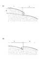
図8を参照して、上記した対物レンズの製造方法を説明する。図8(A)は製造される対物レンズ10を示す断面図であり、図8(B)は本工程で用いられる金型46を示す断面図であり、図8(C)−図8(E)は金型46の一部を拡大して示す断面図である。 With reference to FIG. 8, the manufacturing method of the objective lens described above will be described. FIG. 8A is a cross-sectional view showing the
図8(B)を参照して、本形態の対物レンズ10の製造方法は、先ず、金型46を構成する上金型48と下金型50とを当接させることにより、両者の間にキャビティ19を形成する。そして、ゲート52を経由してキャビティ19に樹脂を注入して硬化させる。その後、上金型48と下金型50とを離間し、硬化した樹脂から成る対物レンズを金型46から取り出す。この工程の詳細を以下に詳述する。 With reference to FIG. 8B, in the manufacturing method of the
上金型48は、図8(A)に示す対物レンズ10の第1レンズ面10Aに対応した形状の内壁48Aを備えている。また、内壁48Aには、第1レンズ面10Aの第1領域F1−第6領域F6に対応して、第1領域S1−第6領域S6が設けられている。第1領域S1−第6領域S6の形状は、第1レンズ面10Aの第1領域F1−第6領域F6の形状を反転させた形状である。従って、上金型48の第1領域S1−第3領域S3には、対物レンズの第1領域F1−第3領域F3に設けられる輪帯段差を反転させた形状の段差部が配置されている。ここで、上金型48は、対物レンズ10の非球面部13A、フランジ部13Bおよび樹脂が流通するランナー部分に分割して構成されても良い。 The upper mold 48 includes an
下金型50は、対物レンズ10の第2レンズ面10Bに即した形状の内壁50Aを備えている。対物レンズ10の第2レンズ面10Bには、基本的には輪帯段差は設けられないので、下金型50の内壁50Aは連続した曲面形状を呈している。上金型48と同様に、下金型50も複数のブロックから構成されても良い。 The lower mold 50 includes an inner wall 50 </ b> A having a shape corresponding to the
本工程では、先ず、上記構成の上金型48と下金型50とを当接させてキャビティ19を構成する。キャビティ19は、図8(A)に示す対物レンズ10に対応した形状を備えている。また、金型46には、キャビティ19と連通して樹脂が注入される部位であるゲート52も設けられる。更に、不図示ではあるが、液状の樹脂が流通するランナー等もキャビティ19に連通して形成される。 In this step, first, the
次に、加熱されて液状または半固形状となった樹脂を、ゲート52からキャビティ19に注入する。ここで、注入される樹脂の材料としては、上記したように、ポリオレフィン樹脂(例えば、環状オレフィンコポリマー、シクロオレフィンポリマー)が採用さる。また、樹脂材料としては、PMMA樹脂(アクリル樹脂)、PC樹脂(ポリカーボネート)等も採用可能である。 Next, the resin that has been heated to become liquid or semi-solid is injected into the
キャビティ19の内部に樹脂を注入した後は、注入された樹脂を硬化させた後に除熱する。その後、上金型48と下金型50とを離間させた後に、金型46から対物レンズ10を取り出す。 After the resin is injected into the
上記工程により、対物レンズ10が製造される。 The
本形態の製造方法では、金型46を用いた射出成形を容易にするために、上金型48に設けられる段差部の高さを調整している。この事項を図8(C)、図8(D)および図8(E)を参照して説明する。ここで、図8(C)は図8(B)に示す上金型48の第1領域S1に設けられる第1段差部49Aを示し、図8(D)は第2領域S2に設けられる第2段差部49Bを示し、図8(E)は第3領域S3に設けられる第3段差部49Cを示している。 In the manufacturing method of this embodiment, the height of the stepped portion provided in the upper mold 48 is adjusted in order to facilitate injection molding using the
これらの図を参照して、上金型48に設けられる第1段差部49A、第2段差部49Bおよび第3段差部49Cは、対物レンズ10の第1領域F1−第3領域F3に設けられる第1輪帯段差51A、第2輪帯段差51Bおよび第3輪帯段差51Cに対応した形状を備えている。 Referring to these drawings, the
例えば、図8(C)を参照すると、対物レンズ10に設けられる第1輪帯段差51Aは、外側の部分が内側よりも厚みが薄くなる形状である。そして、上金型48の第1段差部49Aの内壁形状は、対物レンズの第1輪帯段差51Aの段差形状を逆転させた形状となっている。同様に、図8(D)を参照すると、上金型48の第2段差部49Bの形状は、対物レンズ10の第2輪帯段差51Bの段差形状を逆転させた形状である。また、図8(E)を参照して、上金型48の第3段差部49Cの形状は、対物レンズ10の第3輪帯段差51Cの段差形状を逆転させた形状である。 For example, referring to FIG. 8C, the first
そして本形態では、段差量(絶対値)が大きい第1段差部49Aを、上金型48で最も内側に配置している。一例を述べると、最も内側に配置される第1段差部49Aの段差量H1は、0.0059mmであり、その外側に設けられる第2段差部49Bの段差量H2は−0.0014mmであり、更に外側に設けられる第3段差部49Cの段差量H3は−0.0025mmである。ここで、上金型48に設けられる各段差部の段差量は、対応する箇所の対物レンズ10の輪帯段差の段差量と等しい。 In this embodiment, the first step portion 49 </ b> A having a large step amount (absolute value) is arranged on the innermost side in the upper mold 48. As an example, the step amount H1 of the
これにより、射出成形された対物レンズ10を良好に上金型48から分離できる利点がある。具体的には、キャビティ19に注入された材料を硬化させると、硬化した樹脂からなる対物レンズには硬化収縮が作用する。そして、この硬化収縮の作用は、対物レンズ10の中心から離れるほど大きくなる。従って、成型後に、対物レンズの輪帯段差が上金型48Aの段差部に嵌合し、上金型48から対物レンズ10が離型しづらく成る問題がある。 Thereby, there is an advantage that the injection-molded
離型性を向上させるために本形態では、最も段差量が大きい第1段差部49Aを、内部に配置している。このようにすることで、段差量が大きい第1段差部49Aに作用する硬化収縮による応力が低減され、対物レンズ10が容易に離型可能となる。 In the present embodiment, the
また、図8(C)を参照して、上記した硬化収縮による応力の一部は、紙面上に於いて、上方から下方に向かって作用する。この様な応力が作用する方向を図面では点線の矢印にて示している。この応力は、上記した実線の矢印で示した応力を打ち消して対物レンズの離型を助ける効果を奏すると共に、対物レンズ10の周辺部よりも厚い中央部付近の方が大きくなる。従って、剥離を阻害する要因となる段差量の大きい輪帯段差を、対物レンズの中央部付近に配置することによって、離型性を良好に確保することができる。 Referring to FIG. 8C, a part of the stress due to the curing shrinkage acts on the paper surface from the top to the bottom. The direction in which such stress acts is indicated by dotted arrows in the drawing. This stress has the effect of canceling the stress indicated by the solid line arrow and assisting the release of the objective lens, and is larger in the vicinity of the thick central portion than in the peripheral portion of the
更に、対物レンズ10の中央部付近では、中心部に向かって作用する収縮応力の大部分が紙面上にして下方向(即ち、第1輪帯段差49Aに対して平行な方向)に作用するので、対物レンズ10と上金型48との嵌合が弱い。この様な観点からも、段差量の大きい第1輪帯段差49Aを対物レンズ10の中央部付近に配置することによって、対物レンズ10の離型性が向上される。 Further, in the vicinity of the central portion of the
更にまた、本形態の対物レンズ10は、BD規格、DVD規格およびCD規格のレーザー光を集光する3波長互換対物レンズであり、同一半径の2波長互換レンズ(DVD規格、CD規格)と比較すると、NAが大きい分、中心部分が厚くなる。従って、図8(C)に点線の矢印で示した応力が大きくなり、上記した離型を促進する効果が顕著と成る。 Furthermore, the
更に本形態では、上金型48の第1段差部49Aの形状は、離型を阻害しない形状といている。具体的には、図8(C)を参照して、上金型48の第1段差部49Aと内壁曲面部分とが成す角度θ1を鈍角としている。対物レンズ10を成形することで発生する硬化収縮は、対物レンズ10の中心方向に作用している。この方向を図面では矢印で示している。従って、上記した角度を成す部分の上金型48の内壁は対物レンズ10の表面に密着するが、この部分の角度θ1が鈍角なので密着する程度が低く、対物レンズ10の離型が良好に行われる。 Furthermore, in this embodiment, the shape of the
更に、第1段差部49Aが設けられる部分の内壁48Aは、外側の部分よりも曲率が小さく平坦に近い形状である。従って、第1段差部49Aが設けられた部分の上金型48の内壁は、対物レンズ10と離型しやすい条件にある。 Furthermore, the
一方、図8(D)を参照して、上金型48の第2段差部49Bは、対物レンズ10の第2輪帯段差51Bと嵌合しやすい形状を備えている。その理由は、第2段差部49Bの先端部の角度θ2が鋭角であるからである。更に、第2段差部49Bが配置される部分の内壁形状は曲率が大きいので、対物レンズ10が比較的離型しづらい条件にある。しかしながら、上記したように、第2段差部49Bの段差量は、第1段差部49Aと比較すると小さいので、硬化収縮による嵌合の作用のそれほど大きくない。 On the other hand, referring to FIG. 8D, the second step portion 49 </ b> B of the upper mold 48 has a shape that can be easily fitted to the second annular step 51 </ b> B of the
図8(E)に示す第3段差部49Cも、第1段差部49Aと比較すると段差量が小さいので、図示するような形状であっても対物レンズ10の離型が阻害されることはない。 The third stepped
ここで、上述した製造方法では樹脂材料を射出成形することで対物レンズを成形したが、樹脂材料の替りにガラスを用いることも可能である。この場合は、製造される対物レンズと同体積のガラス材料を用意し、このガラス材料をガラス転移点以上に加熱した後に、金型に投入して押圧する。上記した本形態を、ガラスをモールド成形する製造方法に適用することにより、上記した効果を同様に奏することができる。 Here, in the manufacturing method described above, the objective lens is formed by injection molding of a resin material, but it is also possible to use glass instead of the resin material. In this case, a glass material having the same volume as the objective lens to be manufactured is prepared, and after heating the glass material to a glass transition point or higher, it is put into a mold and pressed. By applying the above-described embodiment to a manufacturing method for molding glass, the above-described effects can be similarly achieved.
更にまた、本形態では、図3(A)等を参照して説明した光学的超解像を採用した結果、図8(B)に示す内壁48Aのレンズ面に相当する部分の端部と、内壁50Aのレンズ面に相当する部分の端部との距離H4が、0.274mm以上に大きく確保される。この結果、キャビティ19に樹脂が良好に注入される。 Furthermore, in this embodiment, as a result of adopting the optical super-resolution described with reference to FIG. 3 (A) and the like, the end of the portion corresponding to the lens surface of the
以上が本形態に係る対物レンズ10およびその製造方法の説明である。 The above is description of the
ここで、上記した輪帯段差および段差部の段差量は、ある程度の幅が許容される。具体的には、第1領域F1での段差量Dを求めるために、上記した式1に代入される波長(λ)の値は、必ずしもBD規格の405nmである必要はなく、例えば395nm〜420nmの範囲で変更されても良い。このように、段差量の算出に用いられる波長を若干変更することにより、BD規格以外のDVD規格またはCD規格のレーザー光に発生する収差が改善される。このことは、第2領域F2および第3領域F3でも同様であり、段差量の算出に使用される波長は、DVD規格の場合は645nm〜675nmで変更可能である。 Here, a certain amount of width is allowed for the steps of the annular zone step and the step portion. Specifically, in order to obtain the step amount D in the first region F1, the value of the wavelength (λ) assigned to the above-described
図9を参照して、上記した構成の対物レンズ10を備えた光ピックアップ装置20の構成を説明する。光ピックアップ装置20は、BD規格、DVD規格またはCD規格のレーザー光を、光ディスク53の情報記録層に集光させ、この情報記録層からの反射光を受光して電気信号に変換する機能を備えている。このことにより、光ピックアップ装置20は、各規格の光ディスク53からの情報の読出または書込を行う。 With reference to FIG. 9, the structure of the optical pick-up apparatus 20 provided with the
本形態の光ピックアップ装置20に含まれる各素子を以下に説明する。 Each element included in the optical pickup device 20 of this embodiment will be described below.
レーザー装置22は、BD規格の波長のレーザー光を出射する。レーザー装置24は、DVD規格およびCD規格の波長のレーザー光を出射する。 The laser device 22 emits laser light having a wavelength of the BD standard. The laser device 24 emits laser light having a wavelength of the DVD standard and the CD standard.
回折格子26は、レーザー装置22と合成プリズム28との間に配置され、BD規格のレーザー光が入射する。そして、回折格子26は、入射するレーザー光を0次光、+1次回折光、−1次回折光に分離する回折格子と、入射するレーザー光を合成プリズム28の偏光面に対してS方向の直線偏光光に変換する1/2波長板とから構成される。同様に、回折格子30は、レーザー装置24と合成プリズム34との間に配置され、回折格子と1/2波長板とから構成される。尚、回折格子30は、DVD規格及びCD規格のレーザー光を合成プリズム34の偏光面に対してS方向の直線偏光光に変換する。 The diffraction grating 26 is disposed between the laser device 22 and the combining prism 28, and receives BD standard laser light. The diffraction grating 26 includes a diffraction grating that separates incident laser light into 0th-order light, + 1st-order diffracted light, and −1st-order diffracted light, and linearly polarized light in the S direction with respect to the polarization plane of the combining prism 28. It comprises a half-wave plate that converts light. Similarly, the diffraction grating 30 is disposed between the laser device 24 and the combining prism 34, and includes a diffraction grating and a half-wave plate. The diffraction grating 30 converts DVD standard and CD standard laser light into linearly polarized light in the S direction with respect to the polarization plane of the combining prism 34.
ダイバージェントレンズ32は、回折格子30と合成プリズム34との間に配置され、回折格子30で回折されたレーザー光の広がり角を調整する。 The divergent lens 32 is disposed between the diffraction grating 30 and the combining prism 34 and adjusts the spread angle of the laser light diffracted by the diffraction grating 30.
合成プリズム28は、波長選択性および偏光選択性を有する偏光面を内蔵し、BD規格のレーザー光には偏光ビームスプリッタとして機能し、DVD規格及びCD規格のレーザー光には、全透過プリズムとして機能する。具体的には、S方向の直線偏光光であるBD規格のレーザー光は、その偏光面により紙面+X方向に反射される。一方、光ディスク53により反射されたレーザー光(戻り光)は、P方向の直線偏光光であり、この偏光面を紙面−X方向に透過する。 The combining prism 28 has a polarization plane having wavelength selectivity and polarization selectivity, functions as a polarizing beam splitter for BD standard laser light, and functions as a total transmission prism for DVD standard and CD standard laser light. To do. Specifically, BD standard laser light, which is linearly polarized light in the S direction, is reflected in the + X direction on the paper surface by the polarization plane. On the other hand, the laser light (return light) reflected by the optical disk 53 is linearly polarized light in the P direction, and passes through this polarization plane in the -X direction on the paper.
合成プリズム34は、波長選択性および偏光選択性を有する偏光面を内蔵し、DVD規格及びCD規格のレーザー光には偏光ビームスプリッタとして機能し、BD規格のレーザー光には、全透過プリズムとして機能する。具体的には、合成プリズム34は、DVD規格及びCD規格のレーザー光の反射率を調整することで、PDIC56へと導かれる第2のレーザー光の光量を調整する。そして、S方向の直線偏光光であるDVD規格及びCD規格のレーザー光の大部分は、その偏光面により紙面+X方向に反射される。一方、光ディスクにより反射されたDVD規格及びCD規格のレーザー光(戻り光)は、P方向の直線偏光光であり、一定の割合にてこの偏光面を紙面−X方向に透過する。 The combining prism 34 has a polarization plane having wavelength selectivity and polarization selectivity, functions as a polarization beam splitter for DVD standard and CD standard laser light, and functions as a total transmission prism for BD standard laser light. To do. Specifically, the combining prism 34 adjusts the light quantity of the second laser light guided to the PDIC 56 by adjusting the reflectivity of the DVD standard and CD standard laser light. And most of the DVD standard and CD standard laser light which is linearly polarized light in the S direction is reflected in the + X direction on the paper surface by the polarization plane. On the other hand, DVD standard and CD standard laser light (return light) reflected by the optical disc is linearly polarized light in the P direction, and is transmitted through the plane of polarization in the −X direction on the paper at a constant rate.
コリメートレンズ36は、BD規格、DVD規格及びCD規格のレーザー光を無限光に変換する。コリメートレンズ36は、点線にて示す光路(光軸)に対して平行方向(紙面±X方向)に移動する。そして、コリメートレンズ36は、それぞれの規格のレーザー光に応じて光学倍率を最適化することで、層間迷光や層間クロストークの発生を抑止する。また、コリメートレンズ36を移動させることにより、レーザー光を弱有限光に変換することができる。 The collimating lens 36 converts BD standard, DVD standard, and CD standard laser light into infinite light. The collimating lens 36 moves in the direction parallel to the optical path (optical axis) indicated by the dotted line (paper surface ± X direction). And the collimating lens 36 suppresses generation | occurrence | production of interlayer stray light and interlayer crosstalk by optimizing an optical magnification according to the laser beam of each specification. Further, by moving the collimating lens 36, the laser light can be converted into weak finite light.
反射ミラー38は、波長選択性および偏光選択性を有する。具体的には、反射ミラー38は、往路のレーザー光を部分的に透過させてFMD23に照射させる。 The reflection mirror 38 has wavelength selectivity and polarization selectivity. Specifically, the reflection mirror 38 partially transmits the forward laser beam to irradiate the FMD 23.
FMD23は、反射ミラー38を透過した往路側のレーザー光を受光し、受光したレーザー光の光量を示す信号を出力する。そして、FMD23の出力に基づいてレーザー装置22、24が制御される。 The FMD 23 receives the forward laser beam transmitted through the reflecting mirror 38 and outputs a signal indicating the amount of the received laser beam. Then, the laser devices 22 and 24 are controlled based on the output of the FMD 23.
反射ミラー40は、各規格の往路のレーザー光を紙面−X方向に全反射する。同様に、光ディスク53により反射された復路のレーザー光(戻り光)も、紙面−Y方向に全反射する。 The reflection mirror 40 totally reflects the forward laser beam of each standard in the -X direction on the paper surface. Similarly, the return path laser light (returned light) reflected by the optical disk 53 is also totally reflected in the -Y direction on the paper surface.
1/4波長板42は、入射するレーザー光に位相差を生じさせ、各規格のレーザー光をS方向の直線偏光光から円偏光光へと変換する。一方、光ディスク53により反射されたレーザー光(戻り光)は、再び1/4波長板42を通過すると、P方向の直線偏光光のレーザー光に変換される。 The quarter-wave plate 42 generates a phase difference in the incident laser light, and converts the laser light of each standard from linearly polarized light in the S direction to circularly polarized light. On the other hand, when the laser light (returned light) reflected by the optical disk 53 passes through the quarter wavelength plate 42 again, it is converted into laser light of linearly polarized light in the P direction.
立ち上げミラー44は、各規格のレーザー光を紙面+Y方向に反射させる。 The raising mirror 44 reflects the laser beam of each standard in the paper surface + Y direction.
対物レンズ10は、立ち上げミラー44により反射されたBD規格、DVD規格及びCD規格のレーザー光を光ディスク53の情報記録層に集光させる。 The
アナモレンズ54は、合成プリズム28とPDIC56との間に配置され、光ディスク53により反射された各規格のレーザー光(戻り光)が通過する。そして、アナモレンズ54は、通過するレーザー光にフォーカスサーボ用の非点収差を付与し、各規格のレーザー光を1つのPDIC56にて対処可能とする。 The anamorphic lens 54 is disposed between the synthesis prism 28 and the PDIC 56, and the laser light (return light) of each standard reflected by the optical disk 53 passes therethrough. The anamorphic lens 54 adds astigmatism for focus servo to the passing laser beam, and allows one standard PDIC 56 to handle each standard laser beam.
PDIC56は、信号検出用のフォトダイオード集積回路素子が内蔵された光検出器であり、各規格のレーザー光を同一平面上の受光領域にて受光し、光電変換によって情報信号成分を含む検出信号を出力する。更に、PDIC56は、フォーカスサーボおよびトラッキングサーボに用いられるサーボ信号成分を含む検出信号を出力する。 The PDIC 56 is a photodetector having a built-in photodiode integrated circuit element for signal detection. The PDIC 56 receives a laser beam of each standard in a light receiving area on the same plane, and receives a detection signal including an information signal component by photoelectric conversion. Output. Further, the PDIC 56 outputs a detection signal including a servo signal component used for focus servo and tracking servo.
次に、DVD規格及びCD規格のレーザー光の光路を説明する。 Next, the optical path of the laser beam of DVD standard and CD standard is demonstrated.
先ず、レーザー装置24から出射されたレーザー光は、回折格子30にて3ビームに分離されるとともに、S方向の直線偏光光に変換され、ダイバージェントレンズ32により所定の広がり角へと調整された後、合成プリズム34へと入射する。その後、レーザー光は、合成プリズム34の偏光面にて反射し、コリメートレンズ36にて無限光に変換された後に、反射ミラー38にて反射する。また、レーザー光の一部は、反射ミラー38を透過してFMD23に照射される。そして、FMD23の出力に基づいてレーザー装置24の出力が制御される。 First, the laser light emitted from the laser device 24 is separated into three beams by the diffraction grating 30, converted into linearly polarized light in the S direction, and adjusted to a predetermined spread angle by the divergent lens 32. Thereafter, the light enters the combining prism 34. Thereafter, the laser light is reflected by the polarization plane of the combining prism 34, converted to infinite light by the collimating lens 36, and then reflected by the reflecting mirror 38. Further, a part of the laser light is transmitted through the reflection mirror 38 and applied to the FMD 23. Then, the output of the laser device 24 is controlled based on the output of the FMD 23.
反射ミラー38で反射されたレーザー光は、反射ミラー40にて全反射され、1/4波長板42を通過することにより、S方向の直線偏光光から円偏光光に変換される。そして、円偏光光のレーザー光は、立ち上げミラー44にて反射した後、対物レンズ10により光ディスク53の情報記録層に集光される。 The laser light reflected by the reflection mirror 38 is totally reflected by the reflection mirror 40 and passes through the quarter-wave plate 42 to be converted from linearly polarized light in the S direction into circularly polarized light. Then, the circularly polarized laser beam is reflected by the rising mirror 44 and then focused on the information recording layer of the optical disc 53 by the
次に、光ディスク53の情報記録層により反射されたレーザー光(戻り光)は、対物レンズ10を透過し、立ち上げミラー44にて反射した後、1/4波長板42を透過することで、円偏光光からP方向の直線偏光光のレーザー光へと変換される。そして、このレーザー光は、反射ミラー40、38で反射された後に、コリメートレンズ36、合成プリズム34、28を透過する。その後、レーザー光は、アナモレンズ54にてフォーカスエラー検出用の非点収差が付与され、PDIC56の受光領域にて受光され、光電変換によって検出信号へと変換される。 Next, the laser light (returned light) reflected by the information recording layer of the optical disk 53 is transmitted through the
次に、BD規格のレーザー光の光路を説明する。 Next, the optical path of BD standard laser light will be described.
先ず、レーザー装置22から出射されたレーザー光は、回折格子26にて3ビームに分離されるとともに、S方向の直線偏光光に変換され、合成プリズム28へと入射する。そして、このレーザー光は、合成プリズム28の偏光面にて全反射した後、合成プリズム34を全透過する。その後、レーザー光は、コリメートレンズ36で無限光とされた後に、反射ミラー38で大部分が反射され、残りの部分が透過する。透過したレーザー光はFMD23で検出され、FMD23の出力に基づいてレーザー装置22の出力が上記と同様に調整される。 First, laser light emitted from the laser device 22 is separated into three beams by the diffraction grating 26, converted into linearly polarized light in the S direction, and enters the combining prism 28. The laser light is totally reflected by the polarization plane of the synthesis prism 28 and then totally passes through the synthesis prism 34. Thereafter, the laser light is converted to infinite light by the collimating lens 36, and then most of the laser light is reflected by the reflecting mirror 38 and the remaining part is transmitted. The transmitted laser light is detected by the FMD 23, and the output of the laser device 22 is adjusted in the same manner as described above based on the output of the FMD 23.
反射ミラー38を反射したレーザー光は、反射ミラー40にて全反射され、1/4波長板42を通過することにより、S方向の直線偏光光から円偏光光に変換される。そして、円偏光光のレーザー光は、立ち上げミラー44にて反射した後、対物レンズ10により光ディスク53の情報記録層に集光される。 The laser light reflected by the reflection mirror 38 is totally reflected by the reflection mirror 40 and passes through the quarter-wave plate 42 to be converted from linearly polarized light in the S direction into circularly polarized light. Then, the circularly polarized laser beam is reflected by the rising mirror 44 and then focused on the information recording layer of the optical disc 53 by the
次に、光ディスク53の情報記録層により反射されたレーザー光(戻り光)は、対物レンズ10を透過し、立ち上げミラー44にて反射し、1/4波長板42を透過することで、円偏光光からP方向の直線偏光光のレーザー光へと変換される。そして、レーザー光は、反射ミラー40、38にて反射された後に、コリメートレンズ36、合成プリズム34、28を透過する。その後、レーザー光は、アナモレンズ54にて非点収差が付与され、PDIC56の受光領域にて受光され、光電変換によって検出信号が出力される。 Next, the laser light (return light) reflected by the information recording layer of the optical disk 53 is transmitted through the
以上が、本形態のレーザー光の各光路の説明である。 The above is description of each optical path of the laser beam of this form.
10 対物レンズ
10A 第1レンズ面
10B 第2レンズ面
11A 共用領域
11B 専用領域
F1 第1領域
F2 第2領域
F3 第3領域
F4 第4領域
F5 第5領域
F6 第6領域
12A,12B,12C 光ディスク
13A 非球面部
13B フランジ部
14A,14B,14C 情報記録層
16A,16B,16C 被覆層
18 台座
19 キャビティ
20 光ピックアップ装置
21 接着材
22 レーザー装置
24 レーザー装置
26 回折格子
28 合成プリズム
30 回折格子
32 ダイバージェントレンズ
34 合成プリズム
36 コリメートレンズ
38 反射ミラー
40 反射ミラー
42 1/4波長板
44 立ち上げミラー
46 モールド金型
48 上金型
48A 内壁
49A 第1段差部
49B 第2段差部
49C 第3段差部
50 下金型
51A 第1輪帯段差
51B 第2輪帯段差
51C 第3輪帯段差
48B 内壁
52 ゲート
53 光ディスク
54 アナモレンズ
56 PDICDESCRIPTION OF
Claims (16)
Translated fromJapanese前記第1波長よりも長い第2波長を有する第2レーザー光を、第2光ディスクの情報記録層に集光させ、
前記両レーザー光よりも長い第3波長を有する第3レーザー光を、第3光ディスクの情報記録層に集光させる、対物レンズであり、
前記対物レンズの中央部付近に配置された領域であり、前記第1レーザー光、前記第2レーザー光および前記第3レーザー光の何れか複数を、対応する光ディスクの前記情報記録層に集光し、第1輪帯段差が設けられた第1共用領域と、
前記第1共用領域よりも外側に配置された領域であり、前記第1レーザー光、前記第2レーザー光および前記第3レーザー光の何れか複数を、対応する光ディスクの前記情報記録層に集光し、第2輪帯段差が設けられた第2共用領域と、を備え、
前記第1共用領域に設けられる前記第1輪帯段差の段差量が、前記第2共用領域に設けられる前記第2輪帯段差の段差量よりも大きいことを特徴とする対物レンズ。Focusing a first laser beam having a first wavelength on the information recording layer of the first optical disc;
Focusing a second laser beam having a second wavelength longer than the first wavelength on the information recording layer of the second optical disc;
An objective lens that focuses a third laser beam having a third wavelength longer than both the laser beams on an information recording layer of a third optical disc;
It is a region arranged near the center of the objective lens, and focuses any one of the first laser beam, the second laser beam, and the third laser beam on the information recording layer of the corresponding optical disc. A first shared area provided with a first annular zone step;
The region is arranged outside the first shared region, and condenses any one of the first laser beam, the second laser beam, and the third laser beam on the information recording layer of the corresponding optical disc. And a second common area provided with a second annular zone step,
The objective lens, wherein a step amount of the first annular zone step provided in the first common area is larger than a step amount of the second annular zone step provided in the second common region.
前記第1輪帯段差の段差量は、前記第1共用領域で集光される前記第1レーザー光、前記第2レーザー光および前記第3レーザー光に発生する収差が0.3λ未満となるように設定されることを特徴とする請求項1から請求項3の何れかに記載の対物レンズ。The first shared area focuses the first laser beam, the second laser beam, and the third laser beam on the information recording layer of the corresponding optical disc,
The step amount of the first annular zone step is such that the aberration generated in the first laser beam, the second laser beam, and the third laser beam collected in the first shared region is less than 0.3λ. The objective lens according to claim 1, wherein the objective lens is set as follows.
前記第2輪帯段差の段差量は、前記第2共用領域で集光される前記第2レーザー光および前記第3レーザー光に発生する収差が0.3λ未満となるように設定されることを特徴とする請求項1から請求項4の何れかに記載の対物レンズ。The second shared area focuses the second laser beam and the third laser beam on the corresponding information recording layer of the optical disc,
The step amount of the second annular zone step is set so that an aberration generated in the second laser beam and the third laser beam collected in the second shared region is less than 0.3λ. The objective lens according to any one of claims 1 to 4, characterized in that:
前記第1輪帯段差の段差量は、前記第2輪帯および前記第3輪帯段差よりも大きいことを特徴とする請求項1から請求項5の何れかに記載の対物レンズ。The information recording layer of the optical disc, which is a ring-shaped region disposed outside the second shared region, and which corresponds to any one of the first laser beam, the second laser beam, and the third laser beam. And a third shared area provided with a third annular step,
The objective lens according to any one of claims 1 to 5, wherein a step amount of the first annular zone step is larger than that of the second annular zone and the third annular zone step.
前記第3輪帯段差の段差量は、前記第3共用領域で集光される前記第1レーザー光および前記第2レーザー光に発生する収差が0.3λ未満となるように設定されることを特徴とする請求項6に記載の対物レンズ。The third shared area focuses the first laser beam and the second laser beam on the information recording layer of the corresponding optical disc,
The step amount of the third annular zone step is set so that an aberration generated in the first laser beam and the second laser beam collected in the third shared region is less than 0.3λ. The objective lens according to claim 6.
前記専用領域は連続する曲面形状を呈することを特徴とする請求項1から請求項7の何れかに記載の対物レンズ。Condensing only the first laser light or the second laser light on the information recording layer of the corresponding optical disc, and having a dedicated area disposed in the peripheral part,
The objective lens according to claim 1, wherein the dedicated region has a continuous curved surface shape.
前記第1レンズ面に対応した形状の内壁を備えた第1金型と、前記第2レンズ面に対応した形状の内壁を備えた第2金型とを当接させてキャビティを構成し、前記キャビティの内部で前記対物レンズの材料を硬化させる工程と、
前記第1金型と前記第2金型とを離型させて対物レンズを取り出す工程と、を備え、
前記第1金型の前記内壁は、前記対物レンズの前記第1レンズ面に設けられる複数の輪帯段差に対応した段差部を有し、
前記第1金型の内壁で内側に配置される前記段差部の段差量を、前記第1金型の内壁で外側に設けられる前記段差部の段差量よりも大きくすることを特徴とする対物レンズの製造方法。An objective lens manufacturing method for manufacturing an objective lens including a first lens surface and a second lens surface facing each other, and having a plurality of annular zone steps on the first lens surface;
A cavity is formed by contacting a first mold having an inner wall having a shape corresponding to the first lens surface and a second mold having an inner wall having a shape corresponding to the second lens surface, Curing the material of the objective lens inside the cavity;
Separating the first mold and the second mold and taking out the objective lens,
The inner wall of the first mold has a step portion corresponding to a plurality of annular zone steps provided on the first lens surface of the objective lens,
An objective lens characterized in that the stepped amount of the stepped portion disposed on the inner side of the inner wall of the first mold is larger than the stepped amount of the stepped portion provided on the outer side of the inner wall of the first mold. Manufacturing method.
前記対物レンズの前記第1レンズ面は、
中央部付近に配置された領域であり、前記第1レーザー光、前記第2レーザー光および前記第3レーザー光の何れか複数を、対応する前記光ディスクの前記情報記録層に集光し、第1輪帯段差が設けられた第1共用領域と、
前記第1共用領域を囲む位置に配置された輪帯状の領域であり、前記第1レーザー光、前記第2レーザー光および前記第3レーザー光の何れか複数を、対応する前記光ディスクの前記情報記録層に集光し、前記第1輪帯段差よりも段差量が小さい第2輪帯段差が設けられた第2共用領域と、を備え、
前記対物レンズの前記第1輪帯段差および前記第2輪対段差に即した形状の、第1段差部および第2段差部が前記第1金型の前記内壁に設けられることを特徴とする請求項11に記載の対物レンズの製造方法。The objective lens includes a first laser beam, a second laser beam having a longer wavelength than the first laser beam, and a third laser beam having a longer wavelength than the both laser beams, and an information recording layer of an optical disc of a corresponding standard. A lens that focuses light on
The first lens surface of the objective lens is
A region arranged near the center, and condensing any one of the first laser beam, the second laser beam, and the third laser beam on the information recording layer of the corresponding optical disc, A first common area provided with an annular step;
The information recording of the optical disc corresponding to a plurality of the first laser beam, the second laser beam, and the third laser beam, which is a ring-shaped region disposed at a position surrounding the first shared region. And a second shared region provided with a second annular step having a step amount smaller than the first annular step,
The first step portion and the second step portion having shapes corresponding to the first annular zone step and the second wheel pair step of the objective lens are provided on the inner wall of the first mold. Item 12. A method for manufacturing the objective lens according to Item 11.
前記第1金型の前記内壁に、前記対物レンズの前記第3輪帯段差に即した形状の第3段差部を設けることを特徴とする請求項11から請求項14の何れかに記載の対物レンズの製造方法。The information recording layer of the optical disc, which is a ring-shaped region disposed outside the second shared region, and which corresponds to any one of the first laser beam, the second laser beam, and the third laser beam. And a third common area provided with a third annular step having a step amount smaller than the first annular step,
The objective according to any one of claims 11 to 14, wherein a third step portion having a shape corresponding to the third annular step of the objective lens is provided on the inner wall of the first mold. Lens manufacturing method.
The objective lens according to claim 11, wherein a material of the objective lens is a resin, and the resin is cured after the semi-solid or liquid resin is filled into the cavity from a gate. Manufacturing method.
Priority Applications (3)
| Application Number | Priority Date | Filing Date | Title |
|---|---|---|---|
| JP2011017835AJP2012160224A (en) | 2011-01-31 | 2011-01-31 | Objective lens, optical pickup device using the same, and manufacturing method for objective lens |
| US13/360,003US8488434B2 (en) | 2011-01-31 | 2012-01-27 | Objective lens, optical pickup apparatus using the same, and method for manufacturing objective lens |
| CN2012100257435ACN102623024A (en) | 2011-01-31 | 2012-01-31 | Objective lens, optical pickup apparatus using the same, and method for manufacturing objective lens |
Applications Claiming Priority (1)
| Application Number | Priority Date | Filing Date | Title |
|---|---|---|---|
| JP2011017835AJP2012160224A (en) | 2011-01-31 | 2011-01-31 | Objective lens, optical pickup device using the same, and manufacturing method for objective lens |
Publications (1)
| Publication Number | Publication Date |
|---|---|
| JP2012160224Atrue JP2012160224A (en) | 2012-08-23 |
Family
ID=46562899
Family Applications (1)
| Application Number | Title | Priority Date | Filing Date |
|---|---|---|---|
| JP2011017835APendingJP2012160224A (en) | 2011-01-31 | 2011-01-31 | Objective lens, optical pickup device using the same, and manufacturing method for objective lens |
Country Status (3)
| Country | Link |
|---|---|
| US (1) | US8488434B2 (en) |
| JP (1) | JP2012160224A (en) |
| CN (1) | CN102623024A (en) |
Cited By (1)
| Publication number | Priority date | Publication date | Assignee | Title |
|---|---|---|---|---|
| WO2019235248A1 (en)* | 2018-06-08 | 2019-12-12 | ソニーセミコンダクタソリューションズ株式会社 | Image capture device |
Families Citing this family (1)
| Publication number | Priority date | Publication date | Assignee | Title |
|---|---|---|---|---|
| US11120774B1 (en)* | 2020-08-13 | 2021-09-14 | Electronic Arts Inc. | Subpixel text rendering |
Family Cites Families (9)
| Publication number | Priority date | Publication date | Assignee | Title |
|---|---|---|---|---|
| TWI239520B (en)* | 2001-10-12 | 2005-09-11 | Konica Corp | Objective lens, optical element, optical pick-up apparatus and optical information recording and/or reproducing apparatus equipped therewith |
| CN1860535B (en)* | 2004-10-29 | 2011-05-11 | 柯尼卡美能达精密光学株式会社 | Objective lens, optical pickup device and optical disk drive device |
| JP4992105B2 (en) | 2005-12-26 | 2012-08-08 | コニカミノルタアドバンストレイヤー株式会社 | Resin molding die and optical element manufacturing method |
| EP2001020A4 (en)* | 2006-03-07 | 2009-04-29 | Konica Minolta Opto Inc | Optical pickup apparatus, objective optical element, and optical information recording and reproducing apparatus |
| US8208361B2 (en)* | 2008-03-18 | 2012-06-26 | Konica Minolta Opto, Inc. | Objective lens and optical pickup apparatus |
| JPWO2009154072A1 (en)* | 2008-06-20 | 2011-11-24 | コニカミノルタオプト株式会社 | Objective lens, optical pickup device and optical disk drive device |
| US8406111B2 (en)* | 2008-07-30 | 2013-03-26 | Konica Minolta Optp, Inc. | Objective lens and optical pickup device |
| CN101882447B (en)* | 2009-05-07 | 2015-04-01 | 柯尼卡美能达精密光学株式会社 | Objective lens, optical pickup device, and optical information recording and reproducing device |
| JP5310386B2 (en)* | 2009-06-18 | 2013-10-09 | ソニー株式会社 | Objective lens, optical pickup and optical disk apparatus |
- 2011
- 2011-01-31JPJP2011017835Apatent/JP2012160224A/enactivePending
- 2012
- 2012-01-27USUS13/360,003patent/US8488434B2/ennot_activeExpired - Fee Related
- 2012-01-31CNCN2012100257435Apatent/CN102623024A/enactivePending
Cited By (4)
| Publication number | Priority date | Publication date | Assignee | Title |
|---|---|---|---|---|
| WO2019235248A1 (en)* | 2018-06-08 | 2019-12-12 | ソニーセミコンダクタソリューションズ株式会社 | Image capture device |
| JPWO2019235248A1 (en)* | 2018-06-08 | 2021-07-26 | ソニーセミコンダクタソリューションズ株式会社 | Imaging device |
| JP7446994B2 (en) | 2018-06-08 | 2024-03-11 | ソニーセミコンダクタソリューションズ株式会社 | Imaging device |
| US12306382B2 (en) | 2018-06-08 | 2025-05-20 | Sony Semiconductor Solutions Corporation | Imaging device |
Also Published As
| Publication number | Publication date |
|---|---|
| US20120195181A1 (en) | 2012-08-02 |
| CN102623024A (en) | 2012-08-01 |
| US8488434B2 (en) | 2013-07-16 |
Similar Documents
| Publication | Publication Date | Title |
|---|---|---|
| JP4315440B2 (en) | Objective lens for optical recording medium and optical pickup device using the same | |
| JP4846975B2 (en) | Optical element, objective optical system, and optical pickup device | |
| CN101667433B (en) | Aberration correction element | |
| CN101971257B (en) | Objective lens and optical pickup apparatus | |
| JP2002006210A (en) | Objective lens for optical recording medium and optical pickup device using the same | |
| KR100647299B1 (en) | Objective lens optical system and optical pickup device employing same | |
| JP5013117B2 (en) | Optical pickup device and objective optical element for optical pickup device | |
| KR20070121004A (en) | Objective optical element for optical pickup device, Optical element for optical pickup device, Objective optical element unit for optical pickup device and optical pickup device | |
| JP2012160224A (en) | Objective lens, optical pickup device using the same, and manufacturing method for objective lens | |
| WO2007123112A1 (en) | Optical pickup device, optical element, optical information recording and reproducing device and design, method of optical element | |
| JP4678462B2 (en) | Objective lens for optical pickup device | |
| JPWO2009128445A1 (en) | Objective lens and optical pickup device | |
| JP2012119017A (en) | Objective lens and optical pickup device using the same | |
| JP2006147078A (en) | Object optics for optical recording medium, and optical pickup apparatus using the same | |
| JP4818896B2 (en) | Coupling lens and optical pickup device | |
| US8441900B2 (en) | Objective lens and optical pick-up device using the same | |
| WO2012093553A1 (en) | Objective lens and optical pickup device using same | |
| JP4329330B2 (en) | Objective optical element and optical pickup device | |
| JP2002050067A (en) | Objective lens for optical pickup device and optical pickup device | |
| JP2012155801A (en) | Optical pickup lens | |
| CN102804268A (en) | Objective lens, optical pickup device, and optical information recording/ reproducing device | |
| JP2007122828A (en) | Optical element having diffractive surface and optical pickup device using the same | |
| US8576685B2 (en) | Objective lens element | |
| JPWO2009147942A1 (en) | Objective lens and optical pickup device | |
| CN101828225A (en) | Optical pickup device, objective optical element for optical pickup device and optical information recorder/reproducer |
Legal Events
| Date | Code | Title | Description |
|---|---|---|---|
| A521 | Written amendment | Free format text:JAPANESE INTERMEDIATE CODE: A821 Effective date:20130708 | |
| RD02 | Notification of acceptance of power of attorney | Free format text:JAPANESE INTERMEDIATE CODE: A7422 Effective date:20130708 | |
| RD04 | Notification of resignation of power of attorney | Free format text:JAPANESE INTERMEDIATE CODE: A7424 Effective date:20130711 | |
| A711 | Notification of change in applicant | Free format text:JAPANESE INTERMEDIATE CODE: A712 Effective date:20130911 |