JP2012151921A - Inverter device and power tool having the same - Google Patents
Inverter device and power tool having the sameDownload PDFInfo
- Publication number
- JP2012151921A JP2012151921AJP2011006445AJP2011006445AJP2012151921AJP 2012151921 AJP2012151921 AJP 2012151921AJP 2011006445 AJP2011006445 AJP 2011006445AJP 2011006445 AJP2011006445 AJP 2011006445AJP 2012151921 AJP2012151921 AJP 2012151921A
- Authority
- JP
- Japan
- Prior art keywords
- output
- battery pack
- voltage
- battery
- circuit
- Prior art date
- Legal status (The legal status is an assumption and is not a legal conclusion. Google has not performed a legal analysis and makes no representation as to the accuracy of the status listed.)
- Pending
Links
Images
Classifications
- H—ELECTRICITY
- H02—GENERATION; CONVERSION OR DISTRIBUTION OF ELECTRIC POWER
- H02J—CIRCUIT ARRANGEMENTS OR SYSTEMS FOR SUPPLYING OR DISTRIBUTING ELECTRIC POWER; SYSTEMS FOR STORING ELECTRIC ENERGY
- H02J7/00—Circuit arrangements for charging or depolarising batteries or for supplying loads from batteries
- H02J7/007—Regulation of charging or discharging current or voltage
- H02J7/00712—Regulation of charging or discharging current or voltage the cycle being controlled or terminated in response to electric parameters
- H—ELECTRICITY
- H02—GENERATION; CONVERSION OR DISTRIBUTION OF ELECTRIC POWER
- H02J—CIRCUIT ARRANGEMENTS OR SYSTEMS FOR SUPPLYING OR DISTRIBUTING ELECTRIC POWER; SYSTEMS FOR STORING ELECTRIC ENERGY
- H02J7/00—Circuit arrangements for charging or depolarising batteries or for supplying loads from batteries
- H02J7/0063—Circuit arrangements for charging or depolarising batteries or for supplying loads from batteries with circuits adapted for supplying loads from the battery
- H—ELECTRICITY
- H02—GENERATION; CONVERSION OR DISTRIBUTION OF ELECTRIC POWER
- H02M—APPARATUS FOR CONVERSION BETWEEN AC AND AC, BETWEEN AC AND DC, OR BETWEEN DC AND DC, AND FOR USE WITH MAINS OR SIMILAR POWER SUPPLY SYSTEMS; CONVERSION OF DC OR AC INPUT POWER INTO SURGE OUTPUT POWER; CONTROL OR REGULATION THEREOF
- H02M7/00—Conversion of AC power input into DC power output; Conversion of DC power input into AC power output
- H02M7/42—Conversion of DC power input into AC power output without possibility of reversal
- H02M7/44—Conversion of DC power input into AC power output without possibility of reversal by static converters
- H—ELECTRICITY
- H02—GENERATION; CONVERSION OR DISTRIBUTION OF ELECTRIC POWER
- H02J—CIRCUIT ARRANGEMENTS OR SYSTEMS FOR SUPPLYING OR DISTRIBUTING ELECTRIC POWER; SYSTEMS FOR STORING ELECTRIC ENERGY
- H02J2207/00—Indexing scheme relating to details of circuit arrangements for charging or depolarising batteries or for supplying loads from batteries
- H02J2207/20—Charging or discharging characterised by the power electronics converter
Landscapes
- Engineering & Computer Science (AREA)
- Power Engineering (AREA)
- Inverter Devices (AREA)
- Charge And Discharge Circuits For Batteries Or The Like (AREA)
- Secondary Cells (AREA)
Abstract
Translated fromJapaneseDescription
Translated fromJapanese本発明は、インバータ装置及びそれを備えた電動工具に関する。 The present invention relates to an inverter device and a power tool including the same.
従来より、インバータ回路を備えた電子機器が知られている。このような電子機器は、商用電源からの交流電力をトランスで変圧し、整流・平滑回路で直流電力に整流・平滑した後、インバータ回路で所定の交流電力に変換してACモータ等に出力している。 Conventionally, an electronic device including an inverter circuit is known. Such an electronic device transforms AC power from a commercial power source with a transformer, rectifies and smoothes it into DC power with a rectifying / smoothing circuit, converts it to predetermined AC power with an inverter circuit, and outputs it to an AC motor or the like. ing.
また、電子機器のACモータを作動させるために、電池パックからの直流電力を交流電力に変換して電子機器に供給するという構成も考えられる(例えば、特許文献1参照)。 Moreover, in order to operate the AC motor of an electronic device, the structure which converts the direct-current power from a battery pack into alternating current power, and supplies it to an electronic device is also considered (for example, refer patent document 1).
ところで、電子機器のACモータを作動させるために、電池パックからの直流電力を交流電力に変換して電子機器に供給するという構成の場合、直流電力を交流電力に変換するために、スイッチング回路と、トランスと、整流・平滑回路と、インバータ回路と、を備えたインバータ装置を電池パックと電子機器との間に接続することとなる。 By the way, in order to operate the AC motor of the electronic device, in a configuration in which DC power from the battery pack is converted into AC power and supplied to the electronic device, a switching circuit and An inverter device including a transformer, a rectifying / smoothing circuit, and an inverter circuit is connected between the battery pack and the electronic device.
しかしながら、電池パックには様々な特性のものがあるため、全ての電池パックから同一の出力を得ようとすると、電池パックの寿命や出力効率を著しく低下させてしまう虞がある。 However, since the battery packs have various characteristics, if the same output is obtained from all the battery packs, there is a possibility that the life and output efficiency of the battery pack may be significantly reduced.
本発明は、電池パックを適切に保護することのできるインバータ装置を提供することを目的としている。 An object of this invention is to provide the inverter apparatus which can protect a battery pack appropriately.
本発明のインバータ装置は、電池パックから供給される直流電圧を交流電圧に変換して出力する変圧回路と、前記変圧回路から出力された交流電圧を整流・平滑して直流電圧として出力する整流・平滑回路と、前記整流・平滑回路から出力された直流電圧を交流電圧に変換して出力するインバータ回路と、前記電池パックの特性に基づき少なくとも前記インバータ回路からの出力あるいは前記変圧回路からの出力の一方を防止する防止手段と、を備えたことを特徴としている。 The inverter device of the present invention includes a transformer circuit that converts a DC voltage supplied from a battery pack to an AC voltage and outputs the AC voltage, and a rectifier / rectifier that rectifies and smoothes the AC voltage output from the transformer circuit and outputs the DC voltage. A smoothing circuit; an inverter circuit that converts the DC voltage output from the rectifying / smoothing circuit to an AC voltage and outputs the output; and at least an output from the inverter circuit or an output from the transformer circuit based on characteristics of the battery pack And a prevention means for preventing one of the above.
このような構成によれば、電池パックの特性に基づきインバータ回路あるいは変圧回路からの少なくとも一方の出力を防止するので、インバータ装置に適していない電池パックがインバータ装置に接続された場合に、電池パックの寿命や出力効率が著しく低下することを防止することができる。 According to such a configuration, since at least one output from the inverter circuit or the transformer circuit is prevented based on the characteristics of the battery pack, when a battery pack that is not suitable for the inverter device is connected to the inverter device, the battery pack The life and output efficiency of the battery can be prevented from significantly decreasing.
また、前記防止手段は、前記電池パックに含まれる二次電池の並列数に基づき少なくとも前記インバータ回路からの出力あるいは前記変圧回路からの出力の一方を防止することが好ましい。 Moreover, it is preferable that the prevention means prevents at least one of the output from the inverter circuit or the output from the transformer circuit based on the parallel number of secondary batteries included in the battery pack.
このような構成によれば、2並列の電池パックに適した仕様にした場合、1並列の電池パックから2並列の電池パックと同一の電流を得ようとして、1並列の電池パックには2並列の電池パックの2倍の電流が流れ、1並列の電池パックの寿命を低下させてしまうことを防止することができる。 According to such a configuration, when the specification is suitable for the two parallel battery packs, the one parallel battery pack tries to obtain the same current as the two parallel battery packs in one parallel battery pack. A current twice as large as that of the battery pack flows, and it is possible to prevent the life of one parallel battery pack from being reduced.
また、前記防止手段は、前記電池パックの定格電圧に基づき少なくとも前記インバータ回路からの出力あるいは前記変圧回路からの出力の一方を防止することが好ましい。 Moreover, it is preferable that the prevention means prevents at least one of the output from the inverter circuit or the output from the transformer circuit based on the rated voltage of the battery pack.
このような構成によれば、所定の定格電圧を有しない電池パックがインバータ装置に接続された場合に変圧回路における変換効率が低下することを防止することができる。 According to such a structure, when the battery pack which does not have a predetermined rated voltage is connected to an inverter apparatus, it can prevent that the conversion efficiency in a transformer circuit falls.
また、前記防止手段は、前記電池パックに含まれる二次電池の種類に基づき前記インバータ回路からの前記交流電圧の出力を防止することが好ましい。 Moreover, it is preferable that the said prevention means prevents the output of the said alternating voltage from the said inverter circuit based on the kind of secondary battery contained in the said battery pack.
このような構成によれば、所定の種類以外の電池パックがインバータ装置に接続された場合に、電池パックに不適切な電流等が流れ、電池パックの寿命が低下することを防止することができる。 According to such a configuration, when a battery pack other than a predetermined type is connected to the inverter device, it is possible to prevent an inappropriate current or the like from flowing through the battery pack and a reduction in the life of the battery pack. .
本発明によれば、電池パックを適切に保護することができる。 According to the present invention, the battery pack can be appropriately protected.
図1及び図2を用いて、本発明の実施の形態によるインバータ装置1について説明する。 An
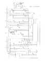
図1は、インバータ装置1の回路図である。インバータ装置1は、電池パック2から供給された直流電力を交流電力に変換して電子機器、例えば電動工具である芝刈機3のACモータ31に供給するために、電池パック2と電子機器3との間に接続されている。ACモータ31には、電子機器3のトリガスイッチ32が操作されると、インバータ装置1から交流電力が供給される。インバータ装置1は、電池パック2と電子機器3との間で着脱可能であるが、以下では、接続されているものとして説明する。 FIG. 1 is a circuit diagram of the
電池パック2は、二次電池からなる電池組21と、電池パック2の電池特性に応じた抵抗値を有する電池特性判別素子22と、プラス側端子23と、マイナス側端子24と、電池特性判別端子25と、を備えており、インバータ装置1には、異なる特性の電池パック2が装着可能である。電池特性としては、電池組21の並列数、定格電圧、及び、種類等が考えられるが、これらに限定されるものではない。 The
インバータ装置1は、電池電圧検出部11と、電源部12と、昇圧回路(変圧回路)13と、整流・平滑回路14と、昇圧電圧検出部15と、インバータ回路16と、電流検出抵抗17と、PWM信号出力部18と、制御部(防止手段)19と、を備えている。 The
電池電圧検出部11は、電池電圧検出抵抗111及び112を備えている。電池電圧検出抵抗111及び112は、電池パック2のプラス側端子23とマイナス側端子24の間に直列に接続されており、電池パック2の電池電圧の、電池電圧検出抵抗111と電池電圧検出抵抗112とによる分圧電圧を制御部19に出力する。なお、図1に示す電池パック2は、3.6V/セルのリチウム電池セルが4本直列接続され、定格電圧14.4Vを出力する。更に、電池パック2はリチウム電池セル4本を一列に直列接続した1並列タイプである。なお、2列に接続したタイプは2並列タイプである。 The battery
電源部12は、電池パック2のプラス側端子23と制御部19との間に直列に接続された電源スイッチ121及び定電圧回路122を備えている。定電圧回路122は、三端子レギュレータ122aと、発振防止用コンデンサ122b及び122cと、を備えており、ユーザにより電源スイッチ121がオンされると、電池パック2からの電圧を所定の直流電圧(例えば5V)に変換し、制御部19に駆動電力として供給する。なお、電源スイッチ121がオフされると、制御部19に駆動電力が供給されなくなるので、インバータ装置1全体がオフされることとなる。 The
電源部12は、更に、電池特性判別抵抗123を備えている。レギュレータ131と電池特性別抵抗123と電池パック2の電池特性別素子22は、電池パック2のプラス側端子23と電池特性別端子25の間に直列に接続されており、レギュレータ131から出力された所定電圧(5V)の、電池特性別抵抗123と電池特性判別素子22とによる分圧電圧が制御部19に出力される。電池特性判別素子22は、電池パック2の電池特性に応じた異なる抵抗値を有しているため、制御部19は、入力された分圧電圧に基づき電池パック2の電池特性を判別し、電池特性(電池種)識別信号を出力する。 The
昇圧回路13は、トランス131と、FET132と、を備えており、トランス131は、一次側巻線131aと、二次側巻線131bと、を備えている。一次側巻線131aは、電池パック2のプラス側端子23とマイナス側端子24の間に接続されており、トランス131の一次側巻線131aとマイナス側端子24の間には、更に、FET132が配置されている。FET132のゲートには、FET132をオン・オフさせるための第1のPWM信号が制御部19から入力され、FET132のオン・オフにより、電池パック2から供給された直流電力は交流電力に変換されて一次側巻線131aと二次側巻線131bとの巻数比に応じて変圧されて二次側巻線131bから出力される。 The
整流・平滑回路14は、整流ダイオード141及び142と、平滑コンデンサ143と、を備えており、これらにより、トランス131により昇圧された交流電力を整流・平滑して直流電力として出力する。 The rectifying /
昇圧電圧検出部15は、互いに直列接続された抵抗151及び152から構成されており、整流・平滑回路14から出力された直流の昇圧電圧(平滑コンデンサ電圧、例えば141V)を検出し、昇圧電圧の、抵抗151と抵抗152とによる分圧電圧を制御部19に出力する。 The
インバータ回路16は、4つのFET161−164から構成されており、直列に接続されたFET161及び162と、直列に接続されたFET163及び164とが、平滑コンデンサ143に並列に接続されている。詳細には、FET161のドレインは、整流ダイオード141及び142のカソードと接続され、FET161のソースは、FET162のドレインに接続されている。また、FET163のドレインは、整流ダイオード141及び142のカソードと接続され、FET163のソースは、FET164のドレインに接続されている。 The
更に、FET161のソース及びFET162のドレイン、FET163のソース及びFET164のドレインは、それぞれ、出力端子165、166と接続されており、出力端子165、166は、電動工具3のACモータ31に接続されている。FET161−164のゲートには、FET161−164をオン・オフさせるための第2のPWM信号がPWM信号出力部18から入力され、FET161−164のオン・オフにより、整流・平滑回路14から出力された直流電力は交流電力に変換されて電子機器3(ACモータ31)に出力される。 Further, the source of the
電流検出抵抗17は、FET162のソース及びFET164のソースと、電池パック2のマイナス側端子24との間に接続されており、電流検出抵抗17の高電圧側の端子は制御部19と接続されている。このような構成により、電流検出抵抗17は、ACモータ31に流れる電流を検出し、電圧として制御部19に出力する。 The
制御部19は、昇圧電圧検出部15によって検出された昇圧電圧に基づき、目標実効値(例えば、141V)を有する交流電力がトランス131の二次側から出力されるような第1のPWM信号をFET132のゲートに出力する。また、制御部19は、目標実効値(例えば、100V)を有する交流電力がACモータ31に出力されるような第2のPWM信号をPWM信号出力部18を介してFET161−164のゲートに出力する。本実施の形態では、制御部19は、FET161とFET164(以降、第1のセット)と、FET162とFET163(以降、第2のセット)とを、それぞれ1セットとして、第1のセットと第2のセットをデューティ比100%で交互にオン・オフさせるような第2のPWM信号を出力する。 Based on the boosted voltage detected by the boosted
また、制御部19は、電池電圧検出部11によって検出された電池電圧に基づき、電池パック2の過放電を判別する。具体的には、電池電圧検出部11によって検出された電池電圧が所定の過放電電圧より小さい場合には、電池パック2に過放電が生じていると判断し、ACモータ31への出力を停止させるための第1のPWM信号及び第2のPWM信号を出力する。すなわち、第1のPWM信号及び第2のPWM信号の出力を停止する。 Further, the
また、電池パック2は、その内部に保護ICやマイコンを備え、自ら過放電を検出して過放電信号を制御部19に出力する機能を有しており、制御部19は、信号端子LDから過放電信号を受信した場合にも、ACモータ31への出力を停止させるための第1のPWM信号及び第2のPWM信号を出力する。すなわち、第1のPWM信号及び第2のPWM信号の出力を停止する。このような構成により、電池パック2の寿命が短くなることを防止することができる。 Further, the
ところで、本実施の形態には異なる特性の電池パック2が接続可能であるが、全ての電池パック2から同一の出力を得ようとすると、電池パック2の寿命や出力効率を著しく低下させてしまう虞がある。例えば、1並列タイプの電池パック2から2並列タイプの電池パック2と同一の電流を得ようとすると、1並列の電池パック2には2並列の電池パック2の2倍の電流が流れることとなり、1並列の電池パック2の寿命を低下させてしまう虞がある。また、電池パック2は、種類によって定格電流が異なるため、同様の理由により電池パック2の寿命を低下させてしまう虞がある。 By the way, although the
更に、通常、トランスの一次側巻線と二次側巻線との巻数比は、所定の電圧が入力された場合に最大の変換効率が得られるような値に設定されているため、所定以外の定格電圧を有する電池パック2がインバータ装置1に接続された場合には、トランス131における変換効率が著しく低下してしまう虞がある。また、この場合、温度上昇が生じるため、温度上昇を防止するために放熱フィン等が必要となり、インバータ装置1が大型化してしまう。 Furthermore, the turns ratio between the primary side winding and the secondary side winding of the transformer is normally set to a value that provides the maximum conversion efficiency when a predetermined voltage is input. When the
そこで、本実施の形態によるインバータ装置1では、電池特性判別素子22から得られる電池特性識別信号に基づいて、インバータ装置1から電動工具3のACモータ31への出力を制御、すなわち、FET132及びFET161−164がオン・オフすることを防止するための第1のPWM信号及び第2のPWM信号を出力する。 Therefore, in the
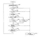
次に、図2のフローチャートを用いて、本実施の形態における制御部19による出力の防止制御について説明する。 Next, output prevention control by the
図2のフローチャートは、電池パック2がインバータ装置1に装着されている状態で電源スイッチ121がオンされた時、又は、電源スイッチ121がオンされた状態で電池パック2がインバータ装置1に装着された時にスタートする。なお、電源スイッチ121をオンすることによって、電池パック2の電圧から定電圧回路122に電圧が供給されることで制御部19の駆動電圧が生成され制御部19が動作することになる。 In the flowchart of FIG. 2, when the
また、本実施の形態によるインバータ装置1には、定格電圧14.4V、定格容量3.0Ah(2並列タイプ)の電池パック2から電力を供給されることに適した構成となっているものとする。 In addition, the
まず、制御部19は、電池特性判別素子22及び電池特性判別抵抗123から電池特性識別信号を検出し(S201)、電池特性識別信号に基づき、インバータ装置1に接続された電池パック2の定格電圧が14.4Vであるか否かを判断する(S202)。14.4Vでない場合、例えば18Vの電池パックの場合には(S202:NO)、インバータ装置1からACモータ31への出力を防止するための第1のPWM信号及び第2のPWM信号を出力する(S210)。すなわち、第1のPWM信号及び第2のPWP信号の出力を停止する。これにより、昇圧回路13及びインバータ回路16の動作が停止され、インバータ装置1からACモータ31への出力が遮断される。この動作は、上記したように、定格電圧14.4Vの電池パック2が接続された際に最も出力効率が良いトランス131を設定しており、18.0Vの電池パックでは出力効率が低下し所望の出力が得られなくなる可能性があるため、ACモータ31への出力を遮断するようにしている。 First, the
一方、14.4Vである場合には(S202:YES)、続いて、電池特性識別信号に基づき、インバータ装置1に接続された電池パック2の定格容量が3.0Ahであるか否かを判断する(S203)。3.0Ahでない場合には(S203:NO)、インバータ装置1からACモータ31への出力を防止するための第1のPWM信号及び第2のPWM信号を出力する(S210)。すなわち、第1のPWM信号及び第2のPWP信号の出力を停止する。この動作は、上記したように、定格容量3.0Ah(2並列タイプ)の電池パックに適した使用にしているためのものである。定格容量1.5Ah(1並列タイプ)の場合には、2並列タイプの電池パック接続時と同様の出力を得ようとして電流が2並列タイプの2倍流れることになり、電池パックの寿命を低下させたり、FET132を故障させてしまう虞がある。 On the other hand, when the voltage is 14.4 V (S202: YES), it is subsequently determined whether the rated capacity of the
一方、3.0Ahである場合には(S203:YES)、本実施の形態によるインバータ装置1に適した電池パック2が接続されていることとなるので、ACモータ31への出力を開始させる。 On the other hand, if it is 3.0 Ah (S203: YES), since the
具体的には、目標実効値(例えば、141V)を有する交流電力がトランス131の二次側から出力されるような第1のPWM信号をFET132のゲートに出力し(S204)、昇圧電圧検出部15によって検出された電圧に基づき、トランス131で昇圧された電圧の実効値が目標実効値より大きいか否かを判断する(S205)。 Specifically, a first PWM signal such that AC power having a target effective value (for example, 141 V) is output from the secondary side of the
昇圧された電圧が目標実効値より大きい場合には(S205:YES)、FET132のデューティ比を減少させ(S206)、昇圧された電圧が目標実効値以下の場合には(S205:NO)、FET132のデューティ比を増加させる(S207)。 When the boosted voltage is larger than the target effective value (S205: YES), the duty ratio of the
続いて、電池電圧検出部11によって検出された電圧に基づき、電池パック2の電池電圧が所定の過放電電圧より小さいか否かを判断する(S208)。所定の過放電電圧より小さい場合には(S208:YES)、電池パック2が過放電状態にあると判断し、ACモータ31への出力を停止させるための第1のPWM信号及び第2のPWM信号を出力する(S210)。すなわち、第1のPWM信号及び第2のPWM信号の出力を停止する。これにより、して昇圧回路13及びインバータ回路16の動作が停止され、インバータ装置1からACモータ31への出力が停止される。 Subsequently, based on the voltage detected by the
また、電池パック2の電池電圧が所定の過放電電圧以上の場合には(S208:NO)、電池パック2からLD端子を介して過放電信号が入力されたか否かを判断する(S209)。過放電信号が入力されていた場合には(S209:YES)、電池パック2が過放電状態にあると判断し、ACモータ31への出力を停止させるための第1のPWM信号及び第2のPWM信号を出力する(S210)。すなわち、第1のPWM信号及び第2のPWM信号の出力を停止する。 If the battery voltage of the
一方、過放電信号が入力されていない場合には(S210:NO)、S201へ戻る。 On the other hand, when the overdischarge signal is not input (S210: NO), the process returns to S201.
以上のように、本実施の形態によるインバータ装置19では、電池特性判別素子22から得られる電池特性識別信号に基づいて、昇圧回路13及びインバータ回路16が動作することを防止する。従って、インバータ装置1に適していない電池パック2がインバータ装置1に接続された場合に、電池パック2の寿命や出力効率が著しく低下することを防止することが可能となる。 As described above, in the
例えば、1並列タイプの電池パック2がインバータ装置1に接続された場合には、上記構成により、1並列タイプの電池パック2の寿命が低下することを防止することができる。 For example, when the one-parallel
また、所定の種類以外の電池パック2がインバータ装置1に接続された場合にも、上記構成により、電池パック2の寿命が低下することを防止することができる。 In addition, even when a
更に、所定の定格電圧を有しない電池パック2(例えば18V)がインバータ装置1に接続された場合には、上記構成により、トランス131における変換効率が低下することを防止することができる。 Furthermore, when a battery pack 2 (for example, 18V) that does not have a predetermined rated voltage is connected to the
尚、本発明の電動工具は、上述した実施の形態に限定されず、特許請求の範囲に記載した範囲で種々の変形や改良が可能である。 The power tool of the present invention is not limited to the above-described embodiment, and various modifications and improvements can be made within the scope described in the claims.
例えば、上記実施の形態では、電池特性判別素子22から得られる電池特性識別信号に基づいて、FET132及びFET161−164がオンすることを防止したが、FET132及びFET161−164のいずれか一方のみがオンすることを防止してもよい。 For example, in the above embodiment, the
また、上記実施の形態では、インバータ装置1に接続された電池パック2の種類を、電池パック2内に設けられた電池特性判別素子22とインバータ装置1内に設けられた電池特性判別抵抗123により判別するように構成したが、判別の方法としてはこの構成に限るものではなく、インバータ装置1に使用できる電池パックと使用できない電池パックとを判別できればよい。 In the above embodiment, the type of the
例えば、電池パックとインバータ装置を接続する判別用端子の有無、すなわち、使用可能な電池パックには充放電用端子以外の端子(判別端子)を設け、使用不可能な電池パックには判別端子を設けないことで判別するようにしてもよい。或いは、種類によって電池パックの接続部やインバータ装置の電池接続部(インバータ装置と電池パックの接続部)を異なる形状にし、機械的に使用できない電池パックはインバータ装置に装着(接続)できないようにしてもよい。 For example, the presence / absence of a discrimination terminal for connecting the battery pack and the inverter device, that is, a usable battery pack is provided with a terminal (discrimination terminal) other than a charge / discharge terminal, and a non-usable battery pack is provided with a discrimination terminal. You may make it discriminate | determine by not providing. Alternatively, depending on the type, the battery pack connection part and the battery connection part of the inverter device (connection part of the inverter device and the battery pack) should have different shapes so that a battery pack that cannot be used mechanically cannot be attached (connected) to the inverter device. Also good.
また、インバータ回路1に接続される電池パック2を14.4Vとして説明したが、種類が異なる電池パック、例えばリチウム電池や、ニカド電池、或いはニッケル水素電池からなる電池パックのいずれかの種類によって出力することを防止するようにしてもよいし、異なる電池電圧(例えば18V)の電池パックに最適な構成としてもよい。 Moreover, although the
また、図2のフローチャートにおける、S204−S207での昇圧電圧の制御、及び、S208−S209での過放電の検出は、フローチャート内のどの位置で行われてもよく、また、並行して行われてもよい。 Further, in the flowchart of FIG. 2, the control of the boosted voltage in S204 to S207 and the overdischarge detection in S208 to S209 may be performed at any position in the flowchart or in parallel. May be.
1 インバータ装置
2 電池パック
13 昇圧回路
14 整流・平滑回路
15 昇圧電圧検出部
16 インバータ回路
19 制御部DESCRIPTION OF
Claims (5)
Translated fromJapanese前記変圧回路から出力された交流電圧を整流・平滑して直流電圧として出力する整流・平滑回路と、
前記整流・平滑回路から出力された直流電圧を交流電圧に変換して出力するインバータ回路と、
前記電池パックの特性に基づき少なくとも前記インバータ回路からの出力あるいは前記変圧回路からの出力の一方を防止する防止手段と、
を備えたことを特徴とするインバータ装置。A transformer circuit that converts the DC voltage supplied from the battery pack into an AC voltage and outputs the AC voltage;
A rectifying / smoothing circuit that rectifies and smoothes the AC voltage output from the transformer circuit and outputs the DC voltage as a DC voltage;
An inverter circuit that converts the DC voltage output from the rectifying / smoothing circuit into an AC voltage and outputs the AC voltage;
Preventing means for preventing at least one of the output from the inverter circuit or the output from the transformer circuit based on the characteristics of the battery pack;
An inverter device comprising:
Priority Applications (5)
| Application Number | Priority Date | Filing Date | Title |
|---|---|---|---|
| JP2011006445AJP2012151921A (en) | 2011-01-14 | 2011-01-14 | Inverter device and power tool having the same |
| US13/978,572US20130285476A1 (en) | 2011-01-14 | 2012-01-16 | Power supply device, inverter device, power tool |
| EP12702321.6AEP2664050A2 (en) | 2011-01-14 | 2012-01-16 | Power supply device, inverter device, power tool |
| CN201280004174.4ACN103503272A (en) | 2011-01-14 | 2012-01-16 | Power supply device, inverter device, power tool |
| PCT/JP2012/000212WO2012096199A2 (en) | 2011-01-14 | 2012-01-16 | Power supply device, inverter device, power tool |
Applications Claiming Priority (1)
| Application Number | Priority Date | Filing Date | Title |
|---|---|---|---|
| JP2011006445AJP2012151921A (en) | 2011-01-14 | 2011-01-14 | Inverter device and power tool having the same |
Publications (2)
| Publication Number | Publication Date |
|---|---|
| JP2012151921Atrue JP2012151921A (en) | 2012-08-09 |
| JP2012151921A5 JP2012151921A5 (en) | 2014-01-30 |
Family
ID=45562412
Family Applications (1)
| Application Number | Title | Priority Date | Filing Date |
|---|---|---|---|
| JP2011006445APendingJP2012151921A (en) | 2011-01-14 | 2011-01-14 | Inverter device and power tool having the same |
Country Status (5)
| Country | Link |
|---|---|
| US (1) | US20130285476A1 (en) |
| EP (1) | EP2664050A2 (en) |
| JP (1) | JP2012151921A (en) |
| CN (1) | CN103503272A (en) |
| WO (1) | WO2012096199A2 (en) |
Cited By (4)
| Publication number | Priority date | Publication date | Assignee | Title |
|---|---|---|---|---|
| JP2014036521A (en)* | 2012-08-09 | 2014-02-24 | Panasonic Corp | Adaptor and power tool |
| JP2015104278A (en)* | 2013-11-27 | 2015-06-04 | 日立工機株式会社 | Electric tool |
| JP2017070079A (en)* | 2015-09-29 | 2017-04-06 | ルネサスエレクトロニクス株式会社 | Motor driving method, battery pack, and semiconductor device |
| US11569765B2 (en) | 2019-10-11 | 2023-01-31 | Black & Decker Inc. | Power tool receiving different capacity battery packs |
Families Citing this family (4)
| Publication number | Priority date | Publication date | Assignee | Title |
|---|---|---|---|---|
| JP5962983B2 (en)* | 2012-08-30 | 2016-08-03 | 日立工機株式会社 | Electric tool |
| US10749430B2 (en) | 2015-03-13 | 2020-08-18 | Positec Power Tools (Suzhou) Co., Ltd. | Power transmission apparatus and control method therefor, and power supply system |
| USD1009790S1 (en) | 2020-03-19 | 2024-01-02 | Milwaukee Electric Tool Corporation | Single battery pack inverter |
| CN115483744A (en)* | 2022-10-17 | 2022-12-16 | 阳光电源股份有限公司 | Method for converting power supply and autonomous power supply of energy storage system |
Citations (7)
| Publication number | Priority date | Publication date | Assignee | Title |
|---|---|---|---|---|
| JPH06348350A (en)* | 1993-06-10 | 1994-12-22 | Matsushita Electric Works Ltd | Power unit |
| JP2000312440A (en)* | 1999-02-26 | 2000-11-07 | Hitachi Koki Co Ltd | Battery charger |
| JP2000350376A (en)* | 1999-06-01 | 2000-12-15 | Sony Corp | Portable electronic equipment |
| JP2006302733A (en)* | 2005-04-22 | 2006-11-02 | Matsushita Electric Ind Co Ltd | Battery pack and connection system thereof |
| JP2008177138A (en)* | 2006-09-19 | 2008-07-31 | Hitachi Koki Co Ltd | Adapter, combination of battery pack and adapter, and electric tool equipped with them |
| JP2009278832A (en)* | 2008-05-16 | 2009-11-26 | Hitachi Koki Co Ltd | Power supply device and power tool system |
| JP2012095458A (en)* | 2010-10-27 | 2012-05-17 | Hitachi Koki Co Ltd | Power supply unit and power tool having the same |
Family Cites Families (8)
| Publication number | Priority date | Publication date | Assignee | Title |
|---|---|---|---|---|
| JPH05198293A (en)* | 1992-01-20 | 1993-08-06 | Sanyo Electric Co Ltd | Battery pack |
| US5291388A (en)* | 1992-04-16 | 1994-03-01 | Westinghouse Electric Corp. | Reconfigurable inverter apparatus for battery-powered vehicle drive |
| CN1801570A (en)* | 2004-12-31 | 2006-07-12 | 乐金电子(昆山)电脑有限公司 | System power supply providing equipment using battery charger |
| JP4555136B2 (en)* | 2005-03-31 | 2010-09-29 | 本田技研工業株式会社 | Fuel cell electrical system, fuel cell vehicle and power supply method |
| US8373381B2 (en)* | 2005-04-22 | 2013-02-12 | GM Global Technology Operations LLC | DC/DC-less coupling of matched batteries to fuel cells |
| JP2007221872A (en)* | 2006-02-15 | 2007-08-30 | Ricoh Co Ltd | Secondary battery charging circuit, power supply switching method and power supply apparatus in secondary battery charging circuit |
| US8698354B2 (en)* | 2010-11-05 | 2014-04-15 | Schneider Electric It Corporation | System and method for bidirectional DC-AC power conversion |
| US20120170325A1 (en)* | 2010-12-31 | 2012-07-05 | Norman Luwei Jin | High Efficiency Solar Wind Inverter With Hybrid DCDC Converter |
- 2011
- 2011-01-14JPJP2011006445Apatent/JP2012151921A/enactivePending
- 2012
- 2012-01-16USUS13/978,572patent/US20130285476A1/ennot_activeAbandoned
- 2012-01-16WOPCT/JP2012/000212patent/WO2012096199A2/enactiveApplication Filing
- 2012-01-16CNCN201280004174.4Apatent/CN103503272A/enactivePending
- 2012-01-16EPEP12702321.6Apatent/EP2664050A2/ennot_activeWithdrawn
Patent Citations (7)
| Publication number | Priority date | Publication date | Assignee | Title |
|---|---|---|---|---|
| JPH06348350A (en)* | 1993-06-10 | 1994-12-22 | Matsushita Electric Works Ltd | Power unit |
| JP2000312440A (en)* | 1999-02-26 | 2000-11-07 | Hitachi Koki Co Ltd | Battery charger |
| JP2000350376A (en)* | 1999-06-01 | 2000-12-15 | Sony Corp | Portable electronic equipment |
| JP2006302733A (en)* | 2005-04-22 | 2006-11-02 | Matsushita Electric Ind Co Ltd | Battery pack and connection system thereof |
| JP2008177138A (en)* | 2006-09-19 | 2008-07-31 | Hitachi Koki Co Ltd | Adapter, combination of battery pack and adapter, and electric tool equipped with them |
| JP2009278832A (en)* | 2008-05-16 | 2009-11-26 | Hitachi Koki Co Ltd | Power supply device and power tool system |
| JP2012095458A (en)* | 2010-10-27 | 2012-05-17 | Hitachi Koki Co Ltd | Power supply unit and power tool having the same |
Cited By (5)
| Publication number | Priority date | Publication date | Assignee | Title |
|---|---|---|---|---|
| JP2014036521A (en)* | 2012-08-09 | 2014-02-24 | Panasonic Corp | Adaptor and power tool |
| JP2015104278A (en)* | 2013-11-27 | 2015-06-04 | 日立工機株式会社 | Electric tool |
| US10486295B2 (en) | 2013-11-27 | 2019-11-26 | Koki Holdings Co., Ltd. | Power tool |
| JP2017070079A (en)* | 2015-09-29 | 2017-04-06 | ルネサスエレクトロニクス株式会社 | Motor driving method, battery pack, and semiconductor device |
| US11569765B2 (en) | 2019-10-11 | 2023-01-31 | Black & Decker Inc. | Power tool receiving different capacity battery packs |
Also Published As
| Publication number | Publication date |
|---|---|
| WO2012096199A2 (en) | 2012-07-19 |
| US20130285476A1 (en) | 2013-10-31 |
| CN103503272A (en) | 2014-01-08 |
| EP2664050A2 (en) | 2013-11-20 |
| WO2012096199A3 (en) | 2013-09-26 |
Similar Documents
| Publication | Publication Date | Title |
|---|---|---|
| JP3826929B2 (en) | Battery pack | |
| JP2012151921A (en) | Inverter device and power tool having the same | |
| JP5567684B2 (en) | Battery balancing circuit and method for balancing energy stored in a plurality of cells of a battery having a first terminal and a second terminal | |
| KR102458732B1 (en) | Battery module and how it works | |
| JP2012191838A (en) | Battery pack, electric tool, adapter for connecting battery pack and electric tool, and electric tool system | |
| CN101272059A (en) | Battery charger operable from a selected one of multiple power sources | |
| US20150311730A1 (en) | Charging Device | |
| JP2016201990A (en) | Vehicle power supply management device | |
| JP2012151920A (en) | Inverter device and power tool having the same | |
| JP5843214B2 (en) | Power tool system and power supply device included in power tool system | |
| JP2014027803A (en) | Power supply | |
| JP2010016976A (en) | Charging system | |
| JP4406932B2 (en) | Charger | |
| JP2009017648A (en) | Charger | |
| CN101331660A (en) | Circuit for small electrical equipment | |
| JP5621415B2 (en) | Battery pack | |
| JP4817054B2 (en) | Charger | |
| JP5679182B2 (en) | Inverter device and electric tool provided with the same | |
| JP2007068264A (en) | Charger | |
| JP2007181263A (en) | Charger | |
| JP5679188B2 (en) | Inverter device and electric tool | |
| JP2012151918A (en) | Inverter device and power tool having the same | |
| JP2012095458A (en) | Power supply unit and power tool having the same | |
| KR101058351B1 (en) | Battery charge / discharge control circuit with regulator and inverter | |
| JP2012191805A (en) | Inverter device and electric tool |
Legal Events
| Date | Code | Title | Description |
|---|---|---|---|
| A521 | Request for written amendment filed | Free format text:JAPANESE INTERMEDIATE CODE: A523 Effective date:20131206 | |
| A621 | Written request for application examination | Free format text:JAPANESE INTERMEDIATE CODE: A621 Effective date:20131206 | |
| A977 | Report on retrieval | Free format text:JAPANESE INTERMEDIATE CODE: A971007 Effective date:20140811 | |
| A131 | Notification of reasons for refusal | Free format text:JAPANESE INTERMEDIATE CODE: A131 Effective date:20140818 | |
| A02 | Decision of refusal | Free format text:JAPANESE INTERMEDIATE CODE: A02 Effective date:20141222 |