JP2012149834A - Heat pump - Google Patents
Heat pumpDownload PDFInfo
- Publication number
- JP2012149834A JP2012149834AJP2011009239AJP2011009239AJP2012149834AJP 2012149834 AJP2012149834 AJP 2012149834AJP 2011009239 AJP2011009239 AJP 2011009239AJP 2011009239 AJP2011009239 AJP 2011009239AJP 2012149834 AJP2012149834 AJP 2012149834A
- Authority
- JP
- Japan
- Prior art keywords
- frequency
- compressor
- heat pump
- heat exchanger
- deviation
- Prior art date
- Legal status (The legal status is an assumption and is not a legal conclusion. Google has not performed a legal analysis and makes no representation as to the accuracy of the status listed.)
- Granted
Links
- 239000003507refrigerantSubstances0.000claimsabstractdescription60
- 230000008859changeEffects0.000claimsabstractdescription53
- 230000004044responseEffects0.000claimsabstractdescription12
- XLYOFNOQVPJJNP-UHFFFAOYSA-NwaterSubstancesOXLYOFNOQVPJJNP-UHFFFAOYSA-N0.000claimsdescription89
- 239000007788liquidSubstances0.000claimsdescription60
- 230000006837decompressionEffects0.000abstractdescription7
- 230000003247decreasing effectEffects0.000abstractdescription4
- 230000004043responsivenessEffects0.000abstract1
- 238000000034methodMethods0.000description14
- 230000006835compressionEffects0.000description10
- 238000007906compressionMethods0.000description10
- 230000008569processEffects0.000description9
- 238000010790dilutionMethods0.000description7
- 239000012895dilutionSubstances0.000description7
- 239000010687lubricating oilSubstances0.000description7
- 238000010438heat treatmentMethods0.000description5
- 230000009467reductionEffects0.000description5
- 239000002826coolantSubstances0.000description4
- 238000001514detection methodMethods0.000description4
- 239000006096absorbing agentSubstances0.000description3
- 238000013459approachMethods0.000description2
- 238000010586diagramMethods0.000description2
- 238000005057refrigerationMethods0.000description2
- 238000010257thawingMethods0.000description2
- 230000002159abnormal effectEffects0.000description1
- 239000002131composite materialSubstances0.000description1
- 230000007423decreaseEffects0.000description1
- 239000007787solidSubstances0.000description1
Images


Classifications
- F—MECHANICAL ENGINEERING; LIGHTING; HEATING; WEAPONS; BLASTING
- F25—REFRIGERATION OR COOLING; COMBINED HEATING AND REFRIGERATION SYSTEMS; HEAT PUMP SYSTEMS; MANUFACTURE OR STORAGE OF ICE; LIQUEFACTION SOLIDIFICATION OF GASES
- F25B—REFRIGERATION MACHINES, PLANTS OR SYSTEMS; COMBINED HEATING AND REFRIGERATION SYSTEMS; HEAT PUMP SYSTEMS
- F25B1/00—Compression machines, plants or systems with non-reversible cycle
- F—MECHANICAL ENGINEERING; LIGHTING; HEATING; WEAPONS; BLASTING
- F24—HEATING; RANGES; VENTILATING
- F24D—DOMESTIC- OR SPACE-HEATING SYSTEMS, e.g. CENTRAL HEATING SYSTEMS; DOMESTIC HOT-WATER SUPPLY SYSTEMS; ELEMENTS OR COMPONENTS THEREFOR
- F24D19/00—Details
- F24D19/0095—Devices for preventing damage by freezing
- F—MECHANICAL ENGINEERING; LIGHTING; HEATING; WEAPONS; BLASTING
- F24—HEATING; RANGES; VENTILATING
- F24D—DOMESTIC- OR SPACE-HEATING SYSTEMS, e.g. CENTRAL HEATING SYSTEMS; DOMESTIC HOT-WATER SUPPLY SYSTEMS; ELEMENTS OR COMPONENTS THEREFOR
- F24D3/00—Hot-water central heating systems
- F24D3/18—Hot-water central heating systems using heat pumps
- F—MECHANICAL ENGINEERING; LIGHTING; HEATING; WEAPONS; BLASTING
- F25—REFRIGERATION OR COOLING; COMBINED HEATING AND REFRIGERATION SYSTEMS; HEAT PUMP SYSTEMS; MANUFACTURE OR STORAGE OF ICE; LIQUEFACTION SOLIDIFICATION OF GASES
- F25B—REFRIGERATION MACHINES, PLANTS OR SYSTEMS; COMBINED HEATING AND REFRIGERATION SYSTEMS; HEAT PUMP SYSTEMS
- F25B49/00—Arrangement or mounting of control or safety devices
- F25B49/02—Arrangement or mounting of control or safety devices for compression type machines, plants or systems
- F25B49/022—Compressor control arrangements
- F—MECHANICAL ENGINEERING; LIGHTING; HEATING; WEAPONS; BLASTING
- F25—REFRIGERATION OR COOLING; COMBINED HEATING AND REFRIGERATION SYSTEMS; HEAT PUMP SYSTEMS; MANUFACTURE OR STORAGE OF ICE; LIQUEFACTION SOLIDIFICATION OF GASES
- F25B—REFRIGERATION MACHINES, PLANTS OR SYSTEMS; COMBINED HEATING AND REFRIGERATION SYSTEMS; HEAT PUMP SYSTEMS
- F25B2500/00—Problems to be solved
- F25B2500/26—Problems to be solved characterised by the startup of the refrigeration cycle
- F—MECHANICAL ENGINEERING; LIGHTING; HEATING; WEAPONS; BLASTING
- F25—REFRIGERATION OR COOLING; COMBINED HEATING AND REFRIGERATION SYSTEMS; HEAT PUMP SYSTEMS; MANUFACTURE OR STORAGE OF ICE; LIQUEFACTION SOLIDIFICATION OF GASES
- F25B—REFRIGERATION MACHINES, PLANTS OR SYSTEMS; COMBINED HEATING AND REFRIGERATION SYSTEMS; HEAT PUMP SYSTEMS
- F25B2600/00—Control issues
- F25B2600/02—Compressor control
- F25B2600/021—Inverters therefor
- F—MECHANICAL ENGINEERING; LIGHTING; HEATING; WEAPONS; BLASTING
- F25—REFRIGERATION OR COOLING; COMBINED HEATING AND REFRIGERATION SYSTEMS; HEAT PUMP SYSTEMS; MANUFACTURE OR STORAGE OF ICE; LIQUEFACTION SOLIDIFICATION OF GASES
- F25B—REFRIGERATION MACHINES, PLANTS OR SYSTEMS; COMBINED HEATING AND REFRIGERATION SYSTEMS; HEAT PUMP SYSTEMS
- F25B2700/00—Sensing or detecting of parameters; Sensors therefor
- F25B2700/19—Pressures
- F25B2700/193—Pressures of the compressor
- F25B2700/1931—Discharge pressures
- F—MECHANICAL ENGINEERING; LIGHTING; HEATING; WEAPONS; BLASTING
- F25—REFRIGERATION OR COOLING; COMBINED HEATING AND REFRIGERATION SYSTEMS; HEAT PUMP SYSTEMS; MANUFACTURE OR STORAGE OF ICE; LIQUEFACTION SOLIDIFICATION OF GASES
- F25B—REFRIGERATION MACHINES, PLANTS OR SYSTEMS; COMBINED HEATING AND REFRIGERATION SYSTEMS; HEAT PUMP SYSTEMS
- F25B2700/00—Sensing or detecting of parameters; Sensors therefor
- F25B2700/21—Temperatures
- F25B2700/2115—Temperatures of a compressor or the drive means therefor
- Y—GENERAL TAGGING OF NEW TECHNOLOGICAL DEVELOPMENTS; GENERAL TAGGING OF CROSS-SECTIONAL TECHNOLOGIES SPANNING OVER SEVERAL SECTIONS OF THE IPC; TECHNICAL SUBJECTS COVERED BY FORMER USPC CROSS-REFERENCE ART COLLECTIONS [XRACs] AND DIGESTS
- Y02—TECHNOLOGIES OR APPLICATIONS FOR MITIGATION OR ADAPTATION AGAINST CLIMATE CHANGE
- Y02B—CLIMATE CHANGE MITIGATION TECHNOLOGIES RELATED TO BUILDINGS, e.g. HOUSING, HOUSE APPLIANCES OR RELATED END-USER APPLICATIONS
- Y02B30/00—Energy efficient heating, ventilation or air conditioning [HVAC]
- Y02B30/12—Hot water central heating systems using heat pumps
- Y—GENERAL TAGGING OF NEW TECHNOLOGICAL DEVELOPMENTS; GENERAL TAGGING OF CROSS-SECTIONAL TECHNOLOGIES SPANNING OVER SEVERAL SECTIONS OF THE IPC; TECHNICAL SUBJECTS COVERED BY FORMER USPC CROSS-REFERENCE ART COLLECTIONS [XRACs] AND DIGESTS
- Y02—TECHNOLOGIES OR APPLICATIONS FOR MITIGATION OR ADAPTATION AGAINST CLIMATE CHANGE
- Y02B—CLIMATE CHANGE MITIGATION TECHNOLOGIES RELATED TO BUILDINGS, e.g. HOUSING, HOUSE APPLIANCES OR RELATED END-USER APPLICATIONS
- Y02B30/00—Energy efficient heating, ventilation or air conditioning [HVAC]
- Y02B30/70—Efficient control or regulation technologies, e.g. for control of refrigerant flow, motor or heating
Landscapes
- Engineering & Computer Science (AREA)
- Physics & Mathematics (AREA)
- Thermal Sciences (AREA)
- Mechanical Engineering (AREA)
- General Engineering & Computer Science (AREA)
- Chemical & Material Sciences (AREA)
- Combustion & Propulsion (AREA)
- Heat-Pump Type And Storage Water Heaters (AREA)
- Air Conditioning Control Device (AREA)
Abstract
Description
Translated fromJapanese本発明は、給湯装置等に適用して好適なヒートポンプに関するものである。 The present invention relates to a heat pump suitable for application to a hot water supply apparatus or the like.
給湯装置用のヒートポンプは、一般に、インバータ駆動の圧縮機と、利用側の第1熱交換器と、減圧手段と、熱源側の第2熱交換器とが順次冷媒配管により接続され、閉サイクルの冷媒回路を構成しており、利用側の第1熱交換器が冷媒と水とを熱交換させて温水を生成する給湯用熱交換器とされている。給湯用熱交換器で生成された温水は、いったん貯湯タンクに貯えられた後、所要箇所に給湯されたり、そのまま出湯されたり、暖房用の熱交換器に循環されたりする等して使用されるようになっている。 In general, a heat pump for a hot water supply apparatus includes an inverter-driven compressor, a first heat exchanger on the use side, a decompression unit, and a second heat exchanger on the heat source side, which are sequentially connected by a refrigerant pipe. A refrigerant circuit is configured, and the first heat exchanger on the use side is a hot water supply heat exchanger that exchanges heat between the refrigerant and water to generate hot water. The hot water generated by the hot water heat exchanger is temporarily stored in a hot water storage tank and then used for hot water supply to a required location, as it is discharged, or circulated to a heat exchanger for heating. It is like that.
このような、給湯装置用のヒートポンプにあって、給湯時の運転立ち上がり時間を短くするには、圧縮機の運転周波数を目標周波数に急上昇させる必要があるが、急激な周波数の上昇は、過負荷や高圧の急上昇(オーバーシュート)、液圧縮等の要因となり、圧縮機の信頼性を低下させる等の問題を惹起する。また、安定運転時においても、給湯用熱交換器への入水温度や外気温度等が変化した場合、それに合わせて圧縮機の運転周波数も適正周波数に変更されるが、急激に変更すると、起動時の場合と同様の問題が発生する。 In such a heat pump for a hot water supply apparatus, in order to shorten the operation rise time at the time of hot water supply, it is necessary to rapidly increase the operation frequency of the compressor to the target frequency. And high pressure surge (overshoot), liquid compression, etc., causing problems such as reducing the reliability of the compressor. In addition, even during stable operation, if the temperature of water entering the heat exchanger for hot water supply or the outside air temperature changes, the operating frequency of the compressor will be changed to an appropriate frequency accordingly. The same problem occurs as in.
そこで、起動時や給湯用熱交換器への入水温度や外気温度等が変化した時、圧縮機の能力を可変すべく、入水温度や外気温度等に基づいて圧縮機の運転周波数を目標周波数に上昇させる場合、過負荷状態となったり、高圧の急激な上昇や液バック等が発生したりしないように、周波数を所定時間毎に段階的に上昇させるようにしたものが特許文献1により提案されている。 Therefore, the compressor operating frequency is set to the target frequency based on the incoming water temperature, the outside air temperature, etc. in order to change the capacity of the compressor when starting up or when the incoming water temperature or the outside air temperature to the heat exchanger for hot water supply changes.
しかしながら、上記特許文献1に示されたものは、圧縮機の運転周波数を目標周波数に上昇させる場合、所定時間T毎に周波数を所定値αずつ一律に段階的に上昇させる構成とされている。このため、目標周波数への到達時間が冗長となり勝ちで、起動時の立ち上がり特性や運転条件の変化に対する応答特性が今一であったり、高圧のオーバーシュートが懸念されたり、液バック対策が不十分であったり等の改善すべき課題があった。 However, the one disclosed in
本発明は、このような事情に鑑みてなされたものであって、起動時の立ち上がり特性や運転条件の変化に対する応答特性を向上させると同時に、過負荷運転や目標周波数付近での高圧のオーバーシュート、液バック等を防止し、圧縮機の信頼性を向上させることができるヒートポンプを提供することを目的とする。 The present invention has been made in view of such circumstances, and improves the start-up characteristics at start-up and the response characteristics to changes in operating conditions, and at the same time, overload operation and high-pressure overshoot near the target frequency. An object of the present invention is to provide a heat pump that prevents liquid back and the like and improves the reliability of the compressor.
上記した課題を解決するために、本発明のヒートポンプは、以下の手段を採用する。
すなわち、本発明にかかるヒートポンプは、インバータ駆動の圧縮機と、利用側の第1熱交換器と、減圧手段と、熱源側の第2熱交換器が順次冷媒配管にて接続され、閉サイクルの冷媒回路が構成されているヒートポンプにおいて、運転条件の変化に対応して前記圧縮機の運転周波数を変更する際、その周波数変更レートを現在周波数と目標周波数との偏差に応じて変化させ、前記偏差が大きいときは前記周波数変更レートを大きくし、前記偏差が小さいときは前記周波数変更レートを小さくして前記運転周波数を変化させる制御部を備えていることを特徴とする。In order to solve the above-described problems, the heat pump of the present invention employs the following means.
That is, in the heat pump according to the present invention, an inverter-driven compressor, a use-side first heat exchanger, a decompression unit, and a heat source-side second heat exchanger are sequentially connected by a refrigerant pipe, and a closed cycle In the heat pump in which the refrigerant circuit is configured, when changing the operating frequency of the compressor in response to a change in operating conditions, the frequency change rate is changed according to the deviation between the current frequency and the target frequency, and the deviation A control unit that changes the operating frequency by increasing the frequency change rate when the deviation is large and decreasing the frequency change rate when the deviation is small.
本発明によれば、インバータ駆動の圧縮機を搭載しているヒートポンプにおいて、運転条件の変化に対応して圧縮機の運転周波数を変更する際、その周波数変更レートを現在周波数と目標周波数との偏差に応じて変化させ、偏差が大きいときは周波数変更レートを大きくし、偏差が小さいときは周波数変更レートを小さくして運転周波数を変化させる制御部を備えているため、起動時や運転条件が変化した場合等で、圧縮機の現在運転周波数と目標周波数との偏差が大きいときは、周波数の変更レートを大きくして運転し、目標周波数との偏差が小さくなるにつれ、周波数の変更レートを漸次小さめにして運転することができる。従って、ヒートポンプの起動時の立ち上がり特性や運転条件の変化に対する応答特性を向上することができるとともに、過負荷運転や目標周波数付近での高圧のオーバーシュート、運転周波数変更時の液バック等を防止し、圧縮機、ひいてはヒートポンプの信頼性を向上することができる。 According to the present invention, in a heat pump equipped with an inverter-driven compressor, when changing the operating frequency of the compressor in response to a change in operating conditions, the frequency change rate is the deviation between the current frequency and the target frequency. The frequency change rate is increased when the deviation is large, and when the deviation is small, the frequency change rate is decreased to change the operating frequency. If the deviation between the current operating frequency of the compressor and the target frequency is large, the frequency change rate is increased, and the frequency change rate is gradually reduced as the deviation from the target frequency decreases. Can drive. Therefore, it is possible to improve the start-up characteristics at the start of the heat pump and the response characteristics to changes in operating conditions, and prevent overload operation, high-pressure overshoot near the target frequency, liquid back when changing the operating frequency, etc. In addition, the reliability of the compressor and thus the heat pump can be improved.
さらに、本発明のヒートポンプは、上記のヒートポンプにおいて、前記制御部は、液バック条件が検知されている間、前記偏差とは無関係に所定の小さい周波数変更レートで前記運転周波数を変化させることを特徴とする。 Furthermore, the heat pump of the present invention is characterized in that, in the above heat pump, the control unit changes the operation frequency at a predetermined small frequency change rate regardless of the deviation while the liquid back condition is detected. And
本発明によれば、制御部が、液バック条件を検知している間、偏差とは無関係に所定の小さい周波数変更レートで運転周波数を変化させるようにしているため、液バック条件が検知され、圧縮機が液圧縮を起こす可能性がある間は、偏差の大小とは無関係に予め設定されている十分小さい周波数変更レートでゆっくりと圧縮機の運転周波数を変化させるようにし、液バック条件を非検知となった時点で、偏差に応じて周波数変更レートを変化させる上記制御に変更することができる。従って、液バックによる液圧縮や潤滑油の希釈等を確実に防止しつつ運転することができ、圧縮機の信頼性を向上することができる。 According to the present invention, while the control unit detects the liquid back condition, the operation frequency is changed at a predetermined small frequency change rate regardless of the deviation, so the liquid back condition is detected, While the compressor is likely to cause liquid compression, the operating frequency of the compressor is changed slowly at a sufficiently small frequency change rate that is set in advance regardless of the magnitude of the deviation, and the liquid back condition is not At the time of detection, the control can be changed to the above control that changes the frequency change rate according to the deviation. Therefore, it is possible to operate while reliably preventing liquid compression by the liquid back, dilution of the lubricating oil, and the like, and the reliability of the compressor can be improved.
また、本発明のヒートポンプは、上記のヒートポンプにおいて、前記液バック条件は、前記圧縮機の密閉ドーム下温度または密閉ドーム内底部温度を検知して判定されることを特徴とする請求項2に記載のヒートポンプ。 Further, in the heat pump of the present invention, in the heat pump described above, the liquid back condition is determined by detecting a temperature under the sealed dome of the compressor or a bottom temperature in the sealed dome. Heat pump.
本発明によれば、液バック条件を圧縮機の密閉ドーム下温度または密閉ドーム内底部温度を検知して判定するようにしているため、サーミスタ等の温度検出手段を圧縮機の密閉ドーム下や密閉ドーム内底部に設け、その検出温度に基づいて液バック条件か否かを判定し、周波数変更レートを適宜変更することによって圧縮機の運転周波数を適正に制御することができる。従って、圧縮機の密閉ドーム下温度や密閉ドーム内底部温度から液バック条件か否かを確実に判定し、液バックによる液圧縮や潤滑油の希釈等の発生を確実に抑止することができる。 According to the present invention, since the liquid back condition is determined by detecting the temperature under the sealed dome of the compressor or the temperature at the bottom of the sealed dome, the temperature detecting means such as the thermistor is used under the sealed dome of the compressor or sealed. The operating frequency of the compressor can be appropriately controlled by providing at the bottom of the dome, determining whether or not the liquid back condition is satisfied based on the detected temperature, and appropriately changing the frequency change rate. Accordingly, it is possible to reliably determine whether or not the liquid back condition is satisfied from the temperature under the sealed dome of the compressor and the temperature at the bottom of the sealed dome, and reliably prevent the occurrence of liquid compression or dilution of lubricating oil due to the liquid back.
また、本発明のヒートポンプは、上記のヒートポンプにおいて、前記液バック条件は、前記圧縮機に吸入される冷媒の吸入過熱度を検知して判定されることを特徴とする請求項2に記載のヒートポンプ。 The heat pump according to claim 2, wherein in the heat pump according to the present invention, the liquid back condition is determined by detecting an intake superheat degree of a refrigerant sucked into the compressor. .
本発明によれば、液バック条件を圧縮機に吸入される冷媒の吸入過熱度を検知して判定するようにしているため、圧縮機に吸入される冷媒の温度および圧力を検知する温度センサおよび圧力センサ等の検出値から吸入過熱度を算出することにより、それに基づいて液バック条件か否かを判定し、周波数変更レートを適宜変更することによって圧縮機の運転周波数を適正に制御することができる。従って、圧縮機に吸入される冷媒の吸入過熱度から液バック条件か否かを確実に判定し、液バックによる液圧縮や潤滑油の希釈等の発生を確実に抑止することができる。 According to the present invention, since the liquid back condition is determined by detecting the superheat degree of the refrigerant sucked into the compressor, the temperature sensor for detecting the temperature and pressure of the refrigerant sucked into the compressor, and By calculating the suction superheat degree from the detection value of the pressure sensor or the like, it is possible to determine whether or not the liquid back condition is based on the calculated value, and to appropriately control the operating frequency of the compressor by appropriately changing the frequency change rate. it can. Therefore, it is possible to reliably determine whether or not the liquid back condition is satisfied from the suction superheat degree of the refrigerant sucked into the compressor, and to reliably prevent the occurrence of liquid compression or dilution of the lubricating oil due to the liquid back.
さらに、本発明のヒートポンプは、上述のいずれかのヒートポンプにおいて、前記ヒートポンプは、前記利用側の第1熱交換器が冷媒/水熱交換器とされた給湯装置用ヒートポンプとされ、該冷媒/水熱交換器への入水温度や外気温度等に変化に対応して前記圧縮機の運転周波数が変更可能とされていることを特徴とする。 Furthermore, the heat pump of the present invention is any one of the heat pumps described above, wherein the heat pump is a heat pump for a hot water supply device in which the first heat exchanger on the use side is a refrigerant / water heat exchanger, and the refrigerant / water The operating frequency of the compressor can be changed in response to changes in the temperature of water entering the heat exchanger, the outside air temperature, and the like.
本発明によれば、ヒートポンプが、利用側の第1熱交換器が冷媒/水熱交換器とされた給湯装置用ヒートポンプとされ、該冷媒/水熱交換器への入水温度や外気温度等に変化に対応して圧縮機の運転周波数が変更可能とされているため、冷媒/水熱交換器への入水温度や外気温度等に応じて圧縮機の能力を変更する場合、圧縮機の現在運転周波数と目標周波数との偏差の大小に応じて周波数変更レートを変化させながら、段階的に圧縮機の運転周波数を可変することができる。従って、給湯時の立ち上がり特性を改善することができるとともに、入水温度の変化等によって、過負荷状態となったり、高圧のオーバーシュートや液バック等が発生したりするのを抑制しながら、安定的にヒートポンプを給湯運転することができる。 According to the present invention, the heat pump is a heat pump for a hot water supply apparatus in which the first heat exchanger on the use side is a refrigerant / water heat exchanger, and the temperature of water entering the refrigerant / water heat exchanger, the outside air temperature, etc. Since the operating frequency of the compressor can be changed in response to the change, if the compressor capacity is changed according to the temperature of the water entering the refrigerant / water heat exchanger or the outside air temperature, the current operation of the compressor The operating frequency of the compressor can be varied step by step while changing the frequency change rate according to the magnitude of the deviation between the frequency and the target frequency. Therefore, it is possible to improve the rise characteristic at the time of hot water supply and to suppress the occurrence of an overload condition, high pressure overshoot, liquid back, etc. due to changes in the incoming water temperature, etc. The heat pump can be operated with hot water.
本発明によると、起動時や運転条件が変化した場合等で、圧縮機の現在運転周波数と目標周波数との偏差が大きいときは、周波数の変更レートを大きくして運転し、目標周波数との偏差が小さくなるにつれ、周波数の変更レートを漸次小さめにして運転することができるため、ヒートポンプの起動時の立ち上がり特性や運転条件の変化に対する応答特性を向上することができるとともに、過負荷運転や目標周波数付近での高圧のオーバーシュート、運転周波数変更時の液バック等を防止し、圧縮機、ひいてはヒートポンプの信頼性を向上することができる。 According to the present invention, when there is a large deviation between the current operating frequency of the compressor and the target frequency, such as when starting up or when the operating conditions change, the operation is performed with a higher frequency change rate, and the deviation from the target frequency. As the frequency becomes smaller, the frequency change rate can be made gradually smaller so that the start-up characteristics at the start of the heat pump and the response characteristics to changes in operating conditions can be improved, as well as overload operation and the target frequency. High pressure overshoot in the vicinity, liquid back at the time of changing the operation frequency, and the like can be prevented, and the reliability of the compressor and thus the heat pump can be improved.
以下に、本発明にかかる実施形態について、図面を参照して説明する。
[第1実施形態]
以下、本発明の第1実施形態について、図1ないし図4を用いて説明する。
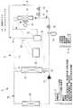
図1には、本発明の一実施形態に係るヒートポンプの冷媒回路図が示されている。
ヒートポンプ1は、給湯装置2に適用されたものである。このヒートポンプ1は、インバータ駆動の電動モータを介して駆動される回転数可変の圧縮機12と、冷凍サイクル18を給湯サイクルとデフロストサイクルとに切換える電磁弁11と、利用側の第1熱交換器(給湯用冷媒/水熱交換器)13と、レシーバ14と、給湯用電子膨張弁(減圧手段)15と、熱源側の第2熱交換器(室外空気熱交換器)16とを備えている。Embodiments according to the present invention will be described below with reference to the drawings.
[First Embodiment]
Hereinafter, a first embodiment of the present invention will be described with reference to FIGS. 1 to 4.
FIG. 1 is a refrigerant circuit diagram of a heat pump according to an embodiment of the present invention.
The
また、ヒートポンプ1は、冷媒配管17を介して上記各機器、すなわち圧縮機12、第1熱交換器(給湯用冷媒/水熱交換器)13、レシーバ14、給湯用電子膨張弁15および第2熱交換器(室外空気熱交換器)16を順次接続し、閉サイクルの冷媒回路(冷凍サイクル)18を構成し、該冷媒回路18の圧縮機12の吐出側と第2熱交換器(室外空気熱交換器)16の入口側との間に、デフロスト用電子膨張弁(減圧手段)10および上記電磁弁11を備えた除霜用のホットガスバイパス回路9を接続したものであり、電磁弁11および給湯用電子膨張弁15の開閉によって、冷媒を実線矢印方向に循環させる給湯サイクルと、破線矢印方向に循環させるデフロストサイクルとに切換え可能な構成とされている。熱源側の第2熱交換器16には、外気を流通させるための室外送風機19が付設されている。 The
利用側の第1熱交換器(給湯用冷媒/水熱交換器)13には、給湯用の温水回路20が接続されており、この第1熱交換器13は、冷媒/水熱交換器とされ、冷媒回路18側を流れる冷媒と、温水回路20側を流れる温水とを熱交換し、所定温度の温水を生成するものである。温水回路20には、温水循環ポンプ21と、暖房用の放熱器22とが設けられており、第1熱交換器13に生成された温水を放熱器22に供給して暖房に供し、そこで温度降下された温水を、温水循環ポンプ21を介して第1熱交換器13に再循環可能な構成とされている。 A hot water
なお、上記した給湯用の温水回路20は、あくまで一例を示したものに過ぎず、これ以外にも、例えば、貯湯タンクを設置し、該貯湯タンクに生成した温水を貯え、そこから必要箇所に温水を給湯可能なシステムとしたり、第1熱交換器13で生成した温水を直接出湯するシステムとしたり、あるいはそれらの複合システムとしたりする等、温水回路20は様々な構成することができるものである。 The hot water supply
また、ヒートポンプ1は、給湯装置2側の負荷等に応じて加熱能力が調整可能とされており、この加熱能力は、圧縮機12の回転数をインバータで可変することによって調整可能とされている。更に、インバータ駆動の圧縮機12は、給湯用の第1熱交換器13に供給される温水または水の入水温度や外気温度、圧縮機12の密閉ドーム下温度等をサーミスタ等の温度センサ31,32,33で検出するとともに、ヒートポンプ1の高圧圧力を高圧センサ34で検出し、これらの検出値に基づいて圧縮機12の運転周波数を制御する制御部30を介して駆動されるようになっている。 Moreover, the heat capacity of the
制御部30は、圧縮機12の運転周波数を変更する変更開始条件が成立すると、図2に示す制御フロー図に従って周波数を変更する制御を行う構成とされている。以下に、図2ないし図4を用いて、その制御内容を具体的に説明する。
ステップS1で、周波数変更開始条件が満たされると、ステップS2に移行し、ここで圧縮機12の密閉ドーム下温度を温度センサ33により検出している。この密閉ドーム下温度は、ステップS3において、ドーム下温度所定値と比較され、「ドーム下温度>ドーム下温度所定値?」が判定される。When the change start condition for changing the operating frequency of the
When the frequency change start condition is satisfied in step S1, the process proceeds to step S2, where the temperature under the sealed dome of the
ステップS3で、ドーム下温度が所定値よりも高く、「YES」と判定されると、ステップS4に移行され、ドーム下温度が所定値よりも低く、「NO」と判定されると、ステップS5に移行されるようになっている。このように、ドーム下温度が所定値よりも低いと判定された場合は、圧縮機12に対して液バックの可能性が高い場合である。このため、ステップS5では、液バックの回避を優先し、周波数変更レートR1を圧縮機12の現在運転周波数と目標周波数との偏差の大小とは無関係に最小にして、所定時間T3毎に周波数を所定値γずつ上昇させるレートR1で周波数を徐々にゆっくりと上昇させ、スタート位置に戻る動作を繰り返すようにしている(図4参照)。 If it is determined in step S3 that the temperature under the dome is higher than the predetermined value and “YES”, the process proceeds to step S4. If the temperature under the dome is lower than the predetermined value and determined as “NO”, step S5 is performed. Has been moved to. As described above, when it is determined that the temperature under the dome is lower than the predetermined value, there is a high possibility of liquid back with respect to the
一方、ステップS3において、ドーム下温度が所定値よりも高く、液バックの虞がないと判定されると、ステップS4に移行し、ここで圧縮機12の運転周波数の現在値と目標周波数(目標値)との偏差が検知され、次のステップS6に移行される。ステップS6では、圧縮機12の運転周波数の現在値と目標値との偏差と、予め設定されている偏差の所定値とが比較され、「現在値と目標値との偏差>偏差の所定値?」が判定される。ステップS6で、現在値と目標値との偏差が所定値よりも大きく、「YES」と判定されると、ステップS7に移行され、現在値と目標値との偏差が所定値よりも小さく、「NO」と判定されると、ステップS8に移行される。 On the other hand, if it is determined in step S3 that the temperature under the dome is higher than the predetermined value and there is no possibility of liquid back, the process proceeds to step S4, where the current value of the operating frequency of the
ステップS8では、現在値と目標値との偏差が所定値よりも小さいと判定されていることから、周波数変更レートR2を比較的小さめとし、所定時間T2毎に周波数を所定値βずつ上昇させるレートR2で周波数を上昇させ、漸次目標値に近づけるようにして高圧がオーバーシュートしないようにしている(図3、図4参照)。一方、ステップS6で、現在値と目標値との偏差が所定値よりも大きいと判定されると、ステップS7に移行し、ヒートポンプ1の高圧側の圧力を高圧センサ34により検出するようにしている。 In step S8, since the deviation between the current value and the target value is determined to be smaller than the predetermined value, the frequency change rate R2 is set to be relatively small, and the frequency is increased by the predetermined value β every predetermined time T2. The frequency is increased by R2 so as to gradually approach the target value so that the high pressure does not overshoot (see FIGS. 3 and 4). On the other hand, if it is determined in step S6 that the deviation between the current value and the target value is larger than the predetermined value, the process proceeds to step S7, and the pressure on the high pressure side of the
高圧の検出値は、ステップS9において、高圧の所定値と比較され、「高圧の所定値>高圧(目標値)?」が判定される。この判定は、高圧が異常上昇して高圧保護機能が作動する可能性の有無を判断するためのものであり、高圧の検出値が所定値未満で、高圧保護機能が作動する虞がないと判断され、「YES」と判定された場合には、ステップS10に移行され、高圧が所定値を超えている場合には、「NO」と判定され、ステップS8に移行されるようになっている。ステップS10では、高圧保護機能が働く虞がないと判断されていることから、周波数変更レートR3を最大とし、所定時間T1毎に周波数を所定値αずつ上昇させるレートR3で周波数を上昇させるようにしている(図3、図4参照)。 In step S9, the detected value of high pressure is compared with a predetermined value of high pressure, and “high pressure predetermined value> high pressure (target value)?” Is determined. This determination is for determining whether or not there is a possibility that the high pressure protection function is activated due to an abnormal increase in high pressure, and it is determined that there is no possibility that the high pressure protection function will be activated if the detected value of the high pressure is less than a predetermined value. If “YES” is determined, the process proceeds to step S10. If the high pressure exceeds a predetermined value, “NO” is determined, and the process proceeds to step S8. In step S10, since it is determined that there is no possibility that the high-voltage protection function works, the frequency change rate R3 is maximized, and the frequency is increased at a rate R3 that increases the frequency by a predetermined value α every predetermined time T1. (See FIGS. 3 and 4).
上記のように、本実施形態においては、周波数変更レートR1,R2,R3、所定時間T1,T2,T3および所定値α,β,γを、それぞれ「R3>R2>R1」、「T1>T2>T3」、「α>β>γ」の関係に設定し、圧縮機12の運転周波数を変更する際、現在周波数と目標周波数との偏差の大小に応じて、偏差が大きいとき、高圧保護機能が作動しないと判断された場合のみ、周波数変更レートを最大値のR3として速やかに目標値に近づけるようにし、また、偏差が小さくなったとき、周波数変更レートをR2に落とし、漸次目標値に近づけるようにして高圧のオーバーシュート等を防止し、更に、液バックの可能性が高い場合には、偏差の大小に無関係に、周波数変更レートを最小値のR1として周波数を徐々にゆっくりと上昇させ、液圧縮を防止するようにしている。 As described above, in the present embodiment, the frequency change rates R1, R2, R3, the predetermined times T1, T2, T3 and the predetermined values α, β, γ are set to “R3> R2> R1”, “T1> T2”, respectively. > T3 ”,“ α> β> γ ”, and when changing the operating frequency of the
以上に説明のヒートポンプ1によると、圧縮機12で圧縮された冷媒を、電磁弁11を閉としておくことにより利用側の第1熱交換器(給湯用冷媒/水熱交換器)13側に循環させ、第1熱交換器13を放熱器、熱源側の第2熱交換器(室外空気熱交換器)16を吸熱器として機能させることにより、第1熱交換器13で温水回路20側を循環する温水または水を加熱することができる。そして、この温水を温水回路20および温水循環ポンプ21を介して放熱器22に給湯することによって、暖房、その他の利用に供することができる。 According to the
また、上記した給湯運転時に、吸熱器側の第2熱交換器16に霜が付着した場合、給湯用電子膨張弁(減圧手段)15を閉、電磁弁11を開とすることによって冷媒の流れをデフロストサイクルに切換え、第2熱交換器16に対し、圧縮機12から吐出された高温高圧のホットガスを、ホットガスバイパス回路9を介して循環させることにより、第2熱交換器16の除霜運転を行うことができる。 In addition, when frost adheres to the
一方、ヒートポンプ1は、温度センサ31,32,33等により、第1熱交換器13に対する温水または水の入水温度、外気温度、圧縮機12の密閉ドーム下温度等が検出されるとともに、高圧センサ34により高圧圧力が検出され、これらの検出値に基づいて制御部30を介してインバータ駆動の圧縮機12の回転数を可変することにより、その能力が調整されている。つまり、起動時や運転条件の変化等に伴って変動する負荷と対応するように、圧縮機12の回転数を可変して能力を調整するため、インバータ駆動の圧縮機12の運転周波数を目標の周波数に変更するようにしている。 On the other hand, in the
この際、図3および図4に示されるように、圧縮機12の現在運転周波数と目標周波数との偏差の大小に応じて、偏差が所定値よりも大きいときには、高圧センサ34の検出値から高圧保護機能が作動しないと判断される場合、周波数変更レートを所定時間T1毎に周波数を所定値αずつ上昇させる最大レートR3とし、速やかに目標値に近づけるようにしている。また、上記偏差が所定値よりも小さくなったときには、周波数変更レートを所定時間T2毎に周波数を所定値βずつ上昇させるレートR2に落とし、漸次目標値に近づけるようにして高圧のオーバーシュート等を防止するようにしている。 At this time, as shown in FIG. 3 and FIG. 4, when the deviation is larger than a predetermined value according to the magnitude of the deviation between the current operating frequency of the
更に、温度センサ33により検出される圧縮機12のドーム下温度から液バックの可能性が高いと判断される場合には、偏差の大小に無関係に、周波数変更レートを所定時間T3毎に周波数を所定値γずつ上昇させる最小レートR1とし、周波数を徐々にゆっくりと上昇させ、液バックによる液圧縮や潤滑油の希釈等を確実に防止しながら運転できるようにしている。 Furthermore, when it is determined that the possibility of liquid back is high from the temperature under the dome of the
斯くして、本実施形態によれば、ヒートポンプ1の起動時の立ち上がり特性や運転条件の変化に対する応答特性を向上することができるとともに、過負荷運転や目標周波数付近での高圧のオーバーシュート、運転周波数変更時の液バック等を防止し、圧縮機12、ひいてはヒートポンプ1の信頼性を向上することができ、該ヒートポンプ1により安定して給湯運転することができる。特に、高圧保護機能が作動しない範囲で周波数変更レートR3を可及的に大きく設定して運転周波数を上昇させることができるため、立ち上がり特性や応答特性を格段に向上することができる。 Thus, according to the present embodiment, it is possible to improve the start-up characteristics at the start-up of the
また、液バック条件が検知されている間は、特に周波数変更レートを最小とするようにしているため、液バックによる液圧縮や潤滑油の希釈等を確実に防止し、圧縮機12の信頼性を向上することができる。
さらに、液バック条件を圧縮機12の密閉ドーム下温度を検知して判定するようにしているため、サーミスタ等の温度センサ33を圧縮機12の密閉ドーム下に設け、その検出温度に基づいて液バック条件か否かを判定し、液バック条件が検知された場合、周波数変更レートを最小レートR1に変更する等により圧縮機12の運転周波数を適正に制御することができる。従って、圧縮機12の密閉ドーム下温度から液バック条件か否かを確実に判定し、液バックによる液圧縮や潤滑油の希釈等の発生を確実に抑止することができる。In addition, since the frequency change rate is particularly minimized while the liquid back condition is detected, liquid compression due to the liquid back, dilution of the lubricating oil, and the like are reliably prevented, and the reliability of the
Further, since the liquid back condition is determined by detecting the temperature under the sealed dome of the
[第2実施形態]
次に、本発明の第2実施形態について説明する。
本実施形態は、上記した第1実施形態に対して、液バック条件を検知する方式が異なっている。その他の点については、第1実施形態と同様であるので説明は省略する。
本実施形態においては、液バック条件の検知方式を、温度センサ33で圧縮機12の密閉ドーム下温度を検知する方式に替えて、圧縮機12に吸入される冷媒の吸入過熱度を検知する方式としている。[Second Embodiment]
Next, a second embodiment of the present invention will be described.
The present embodiment differs from the first embodiment described above in the method for detecting the liquid back condition. Since other points are the same as those in the first embodiment, description thereof will be omitted.
In this embodiment, the detection method of the liquid back condition is changed to a method of detecting the temperature under the sealed dome of the
冷媒の吸入過熱度を検知する方式としては、
(1)吸熱器(蒸発器)として機能している第2熱交換器16から圧縮機12までの間の冷媒配管中に温度センサと圧力センサとを設け、圧縮機12に吸入される冷媒の温度および圧力を検出し、この冷媒圧力から冷媒の飽和温度を算出して温度センサにより検出された冷媒の実温度との差から吸入過熱度を検知する。
(2)第2熱交換器16から圧縮機12までの間の冷媒配管中に設けた温度センサの検出値と、第2熱交換器16中において冷媒の飽和温度を検出できる位置に設けた温度センサの検出値との差から吸入過熱度を検知する。As a method to detect the refrigerant superheat degree,
(1) A temperature sensor and a pressure sensor are provided in the refrigerant pipe between the
(2) The detected value of the temperature sensor provided in the refrigerant pipe between the
(3)第2熱交換器16から圧縮機12までの間の冷媒配管中に気液分離器を設け、該気液分離器と第2熱交換器16との間の冷媒配管中に設けた温度センサおよび圧力センサの検出値に基づいて、上記(1)の如く吸入過熱度を検知する。
等の方式が考えられる。
なお、上記の温度センサや圧力センサとしては、ヒートポンプ1に一般的に設置されている吸入冷媒温度センサや低圧圧力センサ、熱交温度センサ等の既設のセンサをそのまま流用することができる。(3) A gas-liquid separator is provided in the refrigerant pipe between the
Etc. can be considered.
In addition, as said temperature sensor and pressure sensor, the existing sensors generally installed in the
然して、本実施形態によれば、液バック条件を圧縮機12に吸入される冷媒の吸入過熱度を検知して判定することができるため、第1実施形態における圧縮機12のドーム下温度センサ33を不要とし、既設の温度センサや低圧センサを利用してその検出値から冷媒の吸入過熱度を算出することにより、それに基づいて液バック条件か否かを判定し、液バック条件が検知された場合、周波数変更レートを最小レートR1に変更する等により圧縮機12の運転周波数を適正に制御することができる。従って、圧縮機12に吸入される冷媒の吸入過熱度から液バック条件か否かを確実に判定し、液バックによる液圧縮や潤滑油の希釈等の発生を確実に抑止することができる。 However, according to the present embodiment, the liquid back condition can be determined by detecting the degree of suction superheat of the refrigerant sucked into the
なお、本発明は、上記実施形態にかかる発明に限定されるものではなく、その要旨を逸脱しない範囲において、適宜変形が可能である。例えば、上記第1実施形態では、液バック条件を検知するため、圧縮機12の密閉ドーム下温度を検知しているが、密閉ドーム内の温度を検出するようにしてもよい。また、上記実施形態では、ヒートポンプ1の冷媒回路18内に充填される冷媒について特に言及していないが、冷媒については、HFC系冷媒に限らず、CO2冷媒を用いて、ヒートポンプ1を超臨界ヒートポンプサイクルとしてもよい。 In addition, this invention is not limited to the invention concerning the said embodiment, In the range which does not deviate from the summary, it can change suitably. For example, in the first embodiment, the temperature under the sealed dome of the
さらに、上記実施形態では、周波数変更レートR1,R2,R3の関係を、「R3>R2>R1」とするため、所定時間T1,T2,T3および所定値α,β,γの関係を、それぞれ「T1>T2>T3」、「α>β>γ」としているが、所定時間T1,T2,T3は必ずしも「T1>T2>T3」である必要はなく、例えば「T1=T2=T3」であってもよく、要は周波数変更レートR1,R2,R3が、「R3>R2>R1」の関係を満たしておればよい。 Furthermore, in the above embodiment, since the relationship between the frequency change rates R1, R2, and R3 is “R3> R2> R1,” the relationships between the predetermined times T1, T2, and T3 and the predetermined values α, β, and γ are respectively Although “T1> T2> T3” and “α> β> γ” are set, the predetermined times T1, T2, and T3 are not necessarily “T1> T2> T3”. For example, “T1 = T2 = T3”. In short, it is only necessary that the frequency change rates R1, R2, and R3 satisfy the relationship of “R3> R2> R1”.
また、上記実施形態では、給湯サイクルおよびデフロストサイクルの減圧手段に、給湯用電子膨張弁(減圧手段)15およびデフロスト用電子膨張弁(減圧手段)10を設けた例について説明したが、これらの減圧手段10,15は、電子膨張弁に代えて温度式膨張弁や、キャピラリ等の固定絞りとしてもよい。この場合、給湯用減圧手段15の下流側にも電磁弁を設ける必要がある。 Moreover, although the said embodiment demonstrated the example which provided the hot water supply electronic expansion valve (pressure reduction means) 15 and the defrost electronic expansion valve (pressure reduction means) 10 in the pressure reduction means of the hot water supply cycle and the defrost cycle, these pressure reductions were demonstrated. The means 10 and 15 may be a temperature type expansion valve or a fixed throttle such as a capillary instead of the electronic expansion valve. In this case, it is necessary to provide an electromagnetic valve on the downstream side of the hot water supply decompression means 15.
1 ヒートポンプ
2 給湯装置
9 ホットガスバイパス回路
10 デフロスト用電子膨張弁
11 電磁弁
12 圧縮機
13 利用側の第1熱交換器(給湯用冷媒/水熱交換器)
15 給湯用電子膨張弁(減圧手段)
16 熱源側の第2熱交換器(室外空気熱交換器)
17 冷媒配管
18 冷媒回路
20 温水回路
30 制御部
31,32,33 温度センサ
34 高圧センサ
DESCRIPTION OF
15 Electronic expansion valve for hot water supply (pressure reduction means)
16 Heat source side second heat exchanger (outdoor air heat exchanger)
17 Refrigerant piping 18
Claims (5)
Translated fromJapanese運転条件の変化に対応して前記圧縮機の運転周波数を変更する際、その周波数変更レートを現在周波数と目標周波数との偏差に応じて変化させ、前記偏差が大きいときは前記周波数変更レートを大きくし、前記偏差が小さいときは前記周波数変更レートを小さくして前記運転周波数を変化させる制御部を備えていることを特徴とするヒートポンプ。In a heat pump in which a compressor driven by an inverter, a first heat exchanger on the use side, a pressure reducing means, and a second heat exchanger on the heat source side are sequentially connected by a refrigerant pipe to form a closed cycle refrigerant circuit. ,
When changing the operating frequency of the compressor in response to changes in operating conditions, the frequency change rate is changed according to the deviation between the current frequency and the target frequency, and when the deviation is large, the frequency change rate is increased. And when the said deviation is small, the heat pump characterized by including the control part which makes the said frequency change rate small and changes the said operation frequency.
The heat pump is a heat pump for a hot water supply device in which the first heat exchanger on the use side is a refrigerant / water heat exchanger, and responds to changes in the temperature of water entering the refrigerant / water heat exchanger, the outside air temperature, and the like. The heat pump according to any one of claims 1 to 4, wherein an operating frequency of the compressor is changeable.
Priority Applications (2)
| Application Number | Priority Date | Filing Date | Title |
|---|---|---|---|
| JP2011009239AJP6076583B2 (en) | 2011-01-19 | 2011-01-19 | heat pump |
| EP12151332.9AEP2479516A3 (en) | 2011-01-19 | 2012-01-17 | Heat pump |
Applications Claiming Priority (1)
| Application Number | Priority Date | Filing Date | Title |
|---|---|---|---|
| JP2011009239AJP6076583B2 (en) | 2011-01-19 | 2011-01-19 | heat pump |
Publications (2)
| Publication Number | Publication Date |
|---|---|
| JP2012149834Atrue JP2012149834A (en) | 2012-08-09 |
| JP6076583B2 JP6076583B2 (en) | 2017-02-08 |
Family
ID=45507510
Family Applications (1)
| Application Number | Title | Priority Date | Filing Date |
|---|---|---|---|
| JP2011009239AActiveJP6076583B2 (en) | 2011-01-19 | 2011-01-19 | heat pump |
Country Status (2)
| Country | Link |
|---|---|
| EP (1) | EP2479516A3 (en) |
| JP (1) | JP6076583B2 (en) |
Cited By (3)
| Publication number | Priority date | Publication date | Assignee | Title |
|---|---|---|---|---|
| JP2014231975A (en)* | 2013-05-30 | 2014-12-11 | 三菱電機株式会社 | Refrigeration cycle device |
| WO2016187939A1 (en)* | 2015-05-22 | 2016-12-01 | 广东美的暖通设备有限公司 | Frequency control method and system for variable frequency compressor of heat pump hot water machine |
| WO2019087630A1 (en)* | 2017-10-30 | 2019-05-09 | ダイキン工業株式会社 | Air conditioner |
Families Citing this family (1)
| Publication number | Priority date | Publication date | Assignee | Title |
|---|---|---|---|---|
| CN113465113B (en)* | 2021-05-21 | 2022-06-28 | 宁波奥克斯电气股份有限公司 | Control method, device and air conditioner for low temperature refrigeration of air conditioner |
Citations (8)
| Publication number | Priority date | Publication date | Assignee | Title |
|---|---|---|---|---|
| JPS61272557A (en)* | 1985-05-29 | 1986-12-02 | 株式会社東芝 | Refrigeration cycle equipment |
| JPS6272571U (en)* | 1985-10-25 | 1987-05-09 | ||
| JPH07139857A (en)* | 1993-11-12 | 1995-06-02 | Mitsubishi Electric Corp | Air conditioner |
| JPH07180933A (en)* | 1993-12-21 | 1995-07-18 | Mitsubishi Electric Corp | Refrigeration cycle equipment |
| JPH07310959A (en)* | 1994-05-17 | 1995-11-28 | Matsushita Refrig Co Ltd | Air conditioner |
| JP2003247766A (en)* | 2002-02-26 | 2003-09-05 | Kobe Steel Ltd | Temperature controlling method for freezer |
| JP2005147542A (en)* | 2003-11-17 | 2005-06-09 | Matsushita Electric Ind Co Ltd | Heat pump water heater |
| JP2009162425A (en)* | 2008-01-07 | 2009-07-23 | Hoshizaki Electric Co Ltd | Cooling storage |
Family Cites Families (5)
| Publication number | Priority date | Publication date | Assignee | Title |
|---|---|---|---|---|
| JP2555464B2 (en)* | 1990-04-24 | 1996-11-20 | 株式会社東芝 | Refrigeration cycle equipment |
| JP3117339B2 (en)* | 1993-01-27 | 2000-12-11 | 東芝キヤリア株式会社 | Refrigeration cycle device |
| JP3356551B2 (en)* | 1994-07-13 | 2002-12-16 | 東芝キヤリア株式会社 | Air conditioner |
| JP3404150B2 (en)* | 1994-09-28 | 2003-05-06 | 東芝キヤリア株式会社 | Air conditioner and control method thereof |
| KR100567491B1 (en)* | 2002-02-12 | 2006-04-03 | 마츠시타 덴끼 산교 가부시키가이샤 | Heat pump water heater |
- 2011
- 2011-01-19JPJP2011009239Apatent/JP6076583B2/enactiveActive
- 2012
- 2012-01-17EPEP12151332.9Apatent/EP2479516A3/ennot_activeWithdrawn
Patent Citations (9)
| Publication number | Priority date | Publication date | Assignee | Title |
|---|---|---|---|---|
| JPS61272557A (en)* | 1985-05-29 | 1986-12-02 | 株式会社東芝 | Refrigeration cycle equipment |
| JPS6272571U (en)* | 1985-10-25 | 1987-05-09 | ||
| JPH07139857A (en)* | 1993-11-12 | 1995-06-02 | Mitsubishi Electric Corp | Air conditioner |
| JPH07180933A (en)* | 1993-12-21 | 1995-07-18 | Mitsubishi Electric Corp | Refrigeration cycle equipment |
| JPH07310959A (en)* | 1994-05-17 | 1995-11-28 | Matsushita Refrig Co Ltd | Air conditioner |
| JP2003247766A (en)* | 2002-02-26 | 2003-09-05 | Kobe Steel Ltd | Temperature controlling method for freezer |
| JP2005147542A (en)* | 2003-11-17 | 2005-06-09 | Matsushita Electric Ind Co Ltd | Heat pump water heater |
| JP3918804B2 (en)* | 2003-11-17 | 2007-05-23 | 松下電器産業株式会社 | Heat pump water heater |
| JP2009162425A (en)* | 2008-01-07 | 2009-07-23 | Hoshizaki Electric Co Ltd | Cooling storage |
Cited By (6)
| Publication number | Priority date | Publication date | Assignee | Title |
|---|---|---|---|---|
| JP2014231975A (en)* | 2013-05-30 | 2014-12-11 | 三菱電機株式会社 | Refrigeration cycle device |
| WO2016187939A1 (en)* | 2015-05-22 | 2016-12-01 | 广东美的暖通设备有限公司 | Frequency control method and system for variable frequency compressor of heat pump hot water machine |
| WO2019087630A1 (en)* | 2017-10-30 | 2019-05-09 | ダイキン工業株式会社 | Air conditioner |
| JP2019082279A (en)* | 2017-10-30 | 2019-05-30 | ダイキン工業株式会社 | Air conditioner |
| CN111279138A (en)* | 2017-10-30 | 2020-06-12 | 大金工业株式会社 | Air conditioner |
| CN111279138B (en)* | 2017-10-30 | 2021-06-11 | 大金工业株式会社 | Air conditioner |
Also Published As
| Publication number | Publication date |
|---|---|
| EP2479516A2 (en) | 2012-07-25 |
| EP2479516A3 (en) | 2014-04-02 |
| JP6076583B2 (en) | 2017-02-08 |
Similar Documents
| Publication | Publication Date | Title |
|---|---|---|
| US11231199B2 (en) | Air-conditioning apparatus with leak detection control | |
| JP6269756B1 (en) | Refrigeration equipment | |
| US7918097B2 (en) | Air conditioning system | |
| US8925337B2 (en) | Air conditioning systems and methods having free-cooling pump-protection sequences | |
| JP4931848B2 (en) | Heat pump type outdoor unit for hot water supply | |
| CN102829568B (en) | Refrigerating circulatory device and the hot-water central heating device possessing this device | |
| EP3361185A1 (en) | Refrigeration cycle device | |
| EP3301380B1 (en) | Refrigeration cycle device and refrigeration cycle device control method | |
| JPWO2007083794A1 (en) | Air conditioner | |
| JP6138711B2 (en) | Air conditioner | |
| EP3267130B1 (en) | Refrigeration cycle device | |
| US20120167604A1 (en) | Refrigeration cycle apparatus | |
| US20170227260A1 (en) | Heat Pump Heating Apparatus | |
| JP2011007379A (en) | Air conditioner | |
| JP6076583B2 (en) | heat pump | |
| CN108885028A (en) | Refrigeration cycle device | |
| EP3594587B1 (en) | Heat pump hot water supply device | |
| JP2017150689A (en) | Air conditioner | |
| JP5517891B2 (en) | Air conditioner | |
| JP2015014372A (en) | Air conditioner | |
| JP2015148387A (en) | Air conditioner | |
| US20240175614A1 (en) | Heat pump device and hot water supply device | |
| AU2018411936B2 (en) | Hot water supply apparatus | |
| JP7630648B2 (en) | Refrigeration Cycle Equipment | |
| EP4502501A1 (en) | Air conditioner |
Legal Events
| Date | Code | Title | Description |
|---|---|---|---|
| A621 | Written request for application examination | Free format text:JAPANESE INTERMEDIATE CODE: A621 Effective date:20131206 | |
| A977 | Report on retrieval | Free format text:JAPANESE INTERMEDIATE CODE: A971007 Effective date:20140619 | |
| A131 | Notification of reasons for refusal | Free format text:JAPANESE INTERMEDIATE CODE: A131 Effective date:20140805 | |
| A521 | Written amendment | Free format text:JAPANESE INTERMEDIATE CODE: A523 Effective date:20141003 | |
| A02 | Decision of refusal | Free format text:JAPANESE INTERMEDIATE CODE: A02 Effective date:20150428 | |
| A521 | Written amendment | Free format text:JAPANESE INTERMEDIATE CODE: A523 Effective date:20150629 | |
| A911 | Transfer of reconsideration by examiner before appeal (zenchi) | Free format text:JAPANESE INTERMEDIATE CODE: A911 Effective date:20150707 | |
| A912 | Removal of reconsideration by examiner before appeal (zenchi) | Free format text:JAPANESE INTERMEDIATE CODE: A912 Effective date:20150918 | |
| A521 | Written amendment | Free format text:JAPANESE INTERMEDIATE CODE: A523 Effective date:20160725 | |
| A521 | Written amendment | Free format text:JAPANESE INTERMEDIATE CODE: A523 Effective date:20161028 | |
| A61 | First payment of annual fees (during grant procedure) | Free format text:JAPANESE INTERMEDIATE CODE: A61 Effective date:20170111 | |
| R151 | Written notification of patent or utility model registration | Ref document number:6076583 Country of ref document:JP Free format text:JAPANESE INTERMEDIATE CODE: R151 |