JP2012143377A - Balloon catheter - Google Patents
Balloon catheterDownload PDFInfo
- Publication number
- JP2012143377A JP2012143377AJP2011003749AJP2011003749AJP2012143377AJP 2012143377 AJP2012143377 AJP 2012143377AJP 2011003749 AJP2011003749 AJP 2011003749AJP 2011003749 AJP2011003749 AJP 2011003749AJP 2012143377 AJP2012143377 AJP 2012143377A
- Authority
- JP
- Japan
- Prior art keywords
- balloon
- catheter tube
- lumen
- catheter
- distal end
- Prior art date
- Legal status (The legal status is an assumption and is not a legal conclusion. Google has not performed a legal analysis and makes no representation as to the accuracy of the status listed.)
- Granted
Links
Images


Landscapes
- Media Introduction/Drainage Providing Device (AREA)
Abstract
Translated fromJapaneseDescription
Translated fromJapanese本発明は、人体の体腔ないし管腔内に生じた結石等を除去するために用いられるバルーンカテーテルに関する。 The present invention relates to a balloon catheter used for removing stones and the like generated in a body cavity or lumen of a human body.
胆管内に生じた結石、すなわち、胆石を体外に取り出して除去する方法としては、幾つかの方法が知られているが、その一つとして、バルーンカテーテルを用いる方法が知られている。バルーンカテーテルを用いて胆石を胆管内から除去するには、まず、内視鏡を介して、バルーンを収縮させた状態のバルーンカテーテルを十二指腸側から胆管内に挿入して、バルーンを除去すべき胆石の位置より、奥に位置させる。次いで、バルーンを膨張させてから、バルーンカテーテルを引き戻すことにより、バルーンで胆石を掻き出すようにして、胆管外に排出する。 Several methods are known as methods for removing and removing stones generated in the bile duct, that is, gallstones outside the body, and one of them is a method using a balloon catheter. To remove gallstones from the bile duct using a balloon catheter, first, a balloon catheter in a state in which the balloon is deflated is inserted into the bile duct from the duodenum side through an endoscope, and the gallstone to be removed. Be far from the position of. Next, after inflating the balloon, the balloon catheter is pulled back, so that the gallstone is scraped out by the balloon and discharged out of the bile duct.
このように胆石等を除去するために用いられる従来のバルーンカテーテルとしては、例えば、特許文献1に記載された構造を有するものが知られている。特許文献1に記載のバルーンカテーテルでは、カテーテルチューブのバルーンが取り付けられた部分の近位端側の近傍に噴出口が形成されており、カテーテルチューブ内に形成されたルーメンを介して該噴出口から生理食塩水を噴出させることによって、胆管の内壁に残留した胆石や胆泥等を胆管外に流出させることが可能である。 As a conventional balloon catheter used for removing gallstones and the like in this manner, for example, one having a structure described in
しかしながら、従来技術では、噴出口はカテーテルチューブの壁に内外に貫通するように形成された単純な形状の孔であり、生理食塩水はカテーテルチューブの軸心に対して略直交する方向に噴出されるため、噴出された生理食塩水がバルーン側(遠位端側)にも流れてしまい、胆管外(十二指腸側)に十分に流出させることができずに、胆石や胆泥等が残留してしまう場合があった。特に、胆管の形状が十二指腸側に凸となるように袋状になった部分に残留する胆泥を十分に流出させることができない場合があった。 However, in the prior art, the spout is a simple hole formed so as to penetrate the wall of the catheter tube inward and outward, and the physiological saline is spouted in a direction substantially perpendicular to the axis of the catheter tube. Therefore, the injected physiological saline also flows to the balloon side (distal end side), and it cannot flow out of the bile duct (duodenum side) enough, leaving gallstones, gall mud, etc. There was a case. In particular, in some cases, the bile mud remaining in the bag-like portion so that the shape of the bile duct is convex toward the duodenum cannot be sufficiently discharged.
また、カテーテルチューブの挿入性の悪化を抑制しつつ、噴出口から噴出される生理食塩水の流量を増やして胆石や胆泥等の除去を促進できるようにすることも望まれている。 It is also desired to increase the flow rate of physiological saline sprayed from the spout while suppressing the deterioration of the insertion property of the catheter tube to facilitate the removal of gallstones, gall mud and the like.
本発明は、このような点に鑑みてなされたものであり、体腔ないし管腔内に残留した結石等の確実な除去を容易に行い得るようにすることを目的とする。また、これに加えて、カテーテルチューブの挿入性の悪化を抑制しつつ、噴出口から噴出される生理食塩水等の流体の流量を増やして結石等の流出を促進できるようにすることも目的とする。 The present invention has been made in view of these points, and an object of the present invention is to enable easy removal of stones and the like remaining in a body cavity or a lumen. In addition to this, it is also intended to increase the flow rate of fluid such as physiological saline sprayed from the spout while promoting deterioration of the insertion property of the catheter tube, and to promote the outflow of stones and the like. To do.
本発明のバルーンカテーテルは、可撓性材料からなり、遠位端部と近位端部とを有するカテーテルチューブと、伸縮性材料からなり、前記カテーテルチューブの遠位端部に取り付けられたバルーンとを備えたバルーンカテーテルであって、前記カテーテルチューブの表面には、前記バルーンの近位端側の近傍に噴出口が形成されており、前記カテーテルチューブは、前記バルーンを膨張させる第1流体が流通される第1ルーメン、および前記噴出口から噴出させる第2流体が流通される第2ルーメンを有し、前記噴出口は、前記第2流体の噴出方向が前記カテーテルチューブの軸心に対して近位端側を指向して斜交するように形成されたことを特徴とする。 The balloon catheter of the present invention comprises a catheter tube made of a flexible material and having a distal end and a proximal end, and a balloon made of an elastic material and attached to the distal end of the catheter tube. And a balloon outlet is formed in the vicinity of a proximal end side of the balloon on the surface of the catheter tube, and a first fluid for inflating the balloon flows through the catheter tube. And a second lumen through which a second fluid to be ejected from the ejection port is circulated, and the ejection direction of the second fluid is close to the axis of the catheter tube. It is formed so as to be obliquely directed toward the distal end side.
本発明のバルーンカテーテルにおいて、前記噴出口を、該噴出口から噴出される前記第2流体の中心線の方向が前記カテーテルチューブの軸心に対して、60度以下の角度となるように形成することができる。前記噴出口の数としては、一つでも、複数でもよい。 In the balloon catheter of the present invention, the ejection port is formed such that the direction of the center line of the second fluid ejected from the ejection port is at an angle of 60 degrees or less with respect to the axis of the catheter tube. be able to. The number of the jet outlets may be one or plural.
本発明のバルーンカテーテルにおいて、前記バルーンを、膨張させた状態において前記カテーテルチューブの軸心に対して偏在するように設けることができる。この場合において、前記噴出口を、前記バルーンが偏在する側に設けることが好ましい。 In the balloon catheter of the present invention, the balloon can be provided so as to be unevenly distributed with respect to the axis of the catheter tube in an inflated state. In this case, it is preferable to provide the jet outlet on the side where the balloon is unevenly distributed.
本発明のバルーンカテーテルにおいて、前記カテーテルチューブの遠位端部を、近位端部より細径とすることができる。 In the balloon catheter of the present invention, the distal end portion of the catheter tube can be smaller in diameter than the proximal end portion.
本発明のバルーンカテーテルにおいて、前記カテーテルチューブの断面における前記第2ルーメンの形状を、前記第1ルーメンの一部を囲むような略三日月形状とすることができる。この場合において、前記カテーテルチューブの断面における前記第1ルーメンと前記第2ルーメンとの面積比を、1対5〜1対20の範囲内で設定することができる。 In the balloon catheter of the present invention, the shape of the second lumen in the cross section of the catheter tube may be a substantially crescent shape that surrounds a part of the first lumen. In this case, the area ratio of the first lumen and the second lumen in the cross section of the catheter tube can be set within a range of 1: 5 to 1:20.
本発明のバルーンカテーテルによれば、第2流体はカテーテルチューブの軸心に対して近位端側を指向して斜交する方向に噴出されるため、例えば胆石や胆泥等を除去する場合に、これらを胆管外(十二指腸側)に容易に流出させることができる。従って、結石等を確実にかつ容易に除去することができる。特に、胆管の形状が十二指腸側に凸となるようなやや膨らみをもつ袋状になった部分に残留する胆泥等を十分に除去することができる。 According to the balloon catheter of the present invention, the second fluid is ejected in a direction obliquely directed toward the proximal end side with respect to the axis of the catheter tube. For example, when removing gallstones, gall mud, etc. These can be easily discharged out of the bile duct (duodenum side). Therefore, stones and the like can be removed reliably and easily. In particular, it is possible to sufficiently remove bile mud remaining in a bag-like portion having a slightly swollen shape in which the shape of the bile duct is convex toward the duodenum.
本発明のバルーンカテーテルにおいて、カテーテルチューブの遠位端部を、近位端部より細径とすることにより、カテーテルチューブの挿入性の悪化を抑制しつつ、噴出口から噴出される第2流体の流量を増やして結石等の流出を促進することができる。また、本発明のバルーンカテーテルにおいて、カテーテルチューブの断面における第2ルーメンの形状を、第1ルーメンの一部を囲むような略三日月形状とすることにより、カテーテルチューブの太径化を抑制しつつ、噴出口から噴出される流体の流量を増やして結石等の流出を促進することができる。 In the balloon catheter of the present invention, the distal end of the catheter tube has a diameter smaller than that of the proximal end, thereby suppressing the deterioration of the insertion property of the catheter tube and the second fluid ejected from the ejection port. The flow rate can be increased to promote the outflow of stones. In the balloon catheter of the present invention, the shape of the second lumen in the cross section of the catheter tube is a substantially crescent shape that surrounds a part of the first lumen, thereby suppressing the increase in diameter of the catheter tube, By increasing the flow rate of the fluid ejected from the ejection port, it is possible to promote the outflow of stones and the like.
以下、本発明の実施形態を図面に基づいて説明する。なお、本発明のバルーンカテーテルは、体内の体腔ないし管腔内に存在する結石やスラッジ等を除去する医療用処置具として広く適用可能であるが、以下では、胆管内の胆石や胆泥等を除去する場合を一例として説明する。 Hereinafter, embodiments of the present invention will be described with reference to the drawings. The balloon catheter of the present invention can be widely applied as a medical treatment tool for removing stones, sludge, etc. existing in a body cavity or lumen in the body. The case of removing will be described as an example.
まず、図1および図2を参照する。本実施形態のバルーンカテーテル1は、カテーテルチューブ5と、バルーン2と、カバー13と、2つの枝管14a,14bと、2つのハブ15a,15bとを概略備えて構成されている。 First, FIG. 1 and FIG. 2 will be referred to. The
バルーンカテーテル1のカテーテルチューブ5は、可撓性材料によって形成されたチューブであって、体内に挿入される側の端部である遠位端部7と、その他端側に位置する近位端部6とを有している。このカテーテルチューブ5の外径(遠位端部7の外径d1)は、通常、1.0〜4.0mmであり、全長は、通常、500〜2500mmである。また、カテーテルチューブ5の材料は、可撓性を有する材料であれば特に限定されないが、高分子材料であることが好ましく、なかでも、ポリアミド樹脂あるいはポリアミド系エラストマーであることが特に好ましい。 The
カテーテルチューブ5としては、全長に渡って一様な径を有するチューブを用いてもよいが、図1または図3に示すように、バルーン2が取り付けられるカテーテルチューブ5の遠位端部7が、近位端部6より細径であることが好ましい。これにより、カテーテルチューブ5の挿入性を損なうことを抑制しつつ、後述するメインルーメン9内を流通される生理食塩水の流量を大きくして、噴出口12から噴出させる生理食塩水の流量を増やし、胆泥等の流出を促進することができる。また、カテーテルチューブ5の近位端部6の剛直性をある程度保ちながら、遠位端部7を細径にして柔軟にすることによって、バルーンカテーテル1の操作性が向上する。この場合において、カテーテルチューブ5の遠位端部7の外径d1は、近位端部6の外径d2の50〜95%であることが好ましく、60〜90%であることが特に好ましい。 As the
本実施形態では、一例として、遠位端部7の外径d1を1.85mm、近位端部6の外径d2を2.40mmに設定している。従って、カテーテルチューブ5の遠位端部7の外径d1は、近位端部6の外径d2の約77%である。カテーテルチューブ5の遠位端部7の細径部の長さは、カテーテルチューブ5の全長を2000mmとして、50〜400mmの範囲が好ましく、100〜300mmの範囲がさらに好ましい。本実施形態では、一例として、カテーテルチューブ5の遠位端部7の細径部の長さは100mmとしている。 In the present embodiment, as an example, the outer diameter d1 of the
カテーテルチューブ5の遠位端部7を、近位端部6より細径にする手法は特に限定されないが、遠位端部7と近位端部6との接続部分のカテーテルチューブ5を、遠位端に向かって細くなるテーパー状にすることが好ましい。また、遠位端部7を、近位端部6より細径にする他の手法としては、遠位端部7と近位端部6との間に単一のまたは段階的に複数の段差を設けることが挙げられる。本実施形態では、一例として、カテーテルチューブ5の近位端部6側の細径部と遠位端部7側の太径部とを先細のテーパー部で接続している。なお、以下では、このような近位端部6側の細径部と遠位端部7側の太径部とを先細のテーパー部で接続したカテーテルチューブをテーパーチューブと称することがある。 The method of making the
図2〜図6に示すように、本実施形態では、カテーテルチューブ5として、その内部に、バルーンルーメン(第1ルーメン)8と、メインルーメン(第2ルーメン)9とが形成された2ルーメンタイプのものを用いている。バルーンルーメン8は、バルーン2を膨張させるために用いる空気等の流体をバルーン2内部に送るための流路となるルーメンであり、カテーテルチューブ5の近位端部6から、カテーテルチューブ5の遠位端部7にバルーン2の内部に位置するように設けられた開口である流体導出口11まで貫通している。 As shown in FIGS. 2 to 6, in this embodiment, the
メインルーメン9は、胆石の位置を確認する等の目的で体内のX線造影を行う場合における造影剤の流路として、胆泥等の除去を行う場合に噴出させる生理食塩水(第2流体)の流路として、およびカテーテルチューブ1の体内への挿入時の剛性を確保するためのスタイレット(ステンレス等の金属撚り線からなるワイヤ)を挿入する際に用いるルーメンである。このメインルーメン9は、カテーテルチューブ5の近位端部6から、カテーテルチューブ5の遠位端部7の噴出口12まで貫通している。噴出口12は、バルーン2の近位端側の近傍に位置するように設けられた開口であり、メインルーメン9を介して供給される造影剤の注入または生理食塩水を噴出するものである。 The
なお、3ルーメンタイプのカテーテルチューブの断面図である図21に示されているように、スタイレット用のルーメン、造影剤用のルーメンまたはガイドワイヤー用のルーメンとしてのルーメン10を、生理食塩水を流通させるメインルーメン9とは別に設けてもよい。カテーテルチューブ5の太径化を抑制しつつ、メインルーメン9内を流通される生理食塩水の流量を大きくする観点から、メインルーメン9の断面積は、他のルーメンの断面積合計に対し、5倍以上の断面積を有していることが好ましい。また、上記した機能以外の機能を有する他のルーメンを形成することも可能である。 As shown in FIG. 21, which is a cross-sectional view of a three-lumen type catheter tube, the lumen 10 as a lumen for a stylet, a lumen for a contrast medium, or a lumen for a guide wire is replaced with physiological saline. You may provide separately from the
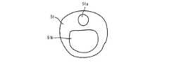
バルーンルーメン8およびメインルーメン9の断面形状は、特に限定されないが、それぞれをカテーテルチューブ5内に効率的に配置することが好ましい。本実施形態では、図4(遠位端部7側の細径部の断面図)または図5(近位端部6側の太径部の断面図)に示されているように、バルーンルーメン8の断面形状を略円形または略楕円形として、メインルーメン9の断面形状を、バルーンルーメン8の一部(半分〜1/3程度)を囲むような略三日月形状としている。メインルーメン9をこのような略三日月形状とすることにより、カテーテルチューブ5内の無駄な部分(例えば、図18に示す従来構造におけるバルーンルーメン51aの両側の部分)を有効利用することができ、メインルーメン9の断面積をより大きくすることができるので、メインルーメン9内を流通させる生理食塩水の流量をより大きくすることができる。 The cross-sectional shapes of the
バルーンルーメン8の断面積は、0.03〜0.3mm2程度である。また、メインルーメン9の断面積は、カテーテルチューブ5の強度を損なわない範囲でなるべく大きくすることが好ましく、0.08〜0.8mm2であることが好ましい。カテーテルチューブ5の断面におけるバルーンルーメン8とメインルーメン9との面積比は、1対5〜1対20の範囲内で設定することができる。本実施形態では、一例として、バルーンルーメン8の断面積は、近位端部6側の太径部において0.24mm2、遠位端部7側の細径部において0.17mm2としている。メインルーメン9の断面積は、近位端部6側の太径部において2.01mm2、遠位端部7側の細径部において1.22mm2としている。従って、カテーテルチューブ5の断面におけるバルーンルーメン8とメインルーメン9との面積比は、1対12である。The cross-sectional area of the
メインルーメン9を介して供給される生理食塩水を噴出させる噴出口12は、図6に示されているように、生理食塩水の噴出方向(噴出口12の中心線の方向)A1がカテーテルチューブ5の軸心A2に対して近位端部6側を指向して斜交するように形成された孔である。この斜交角度は、60度以下(0〜60度)が好ましく、45度以下(0〜45度)がより好ましい。本実施形態では、噴出口12は、カテーテルチューブ5の壁面にカテーテルチューブ5の軸心A2に対して、その中心線A1がθ=45度の角度となるように、内外に貫通して穿孔することにより形成している。噴出口12の形状はその中心線A1に直交する面において略円形または略楕円形とすることができる。また、噴出口12は、その中心線A1に沿って先細にまたは先太になるようにテーパー状となっていてもよい。 As shown in FIG. 6, the
噴出口12の数は、本実施形態では、一つとしている。但し、噴出口12は、複数設けてもよい。噴出口12を複数設ける場合には、カテーテルチューブ5の軸心A2に沿う方向に複数設けてもよいし、軸心A2に直交する断面において放射状に複数設けてもよいし、これらの組み合わせとしてもよい。また、噴出口12は、軸心A2に直交する断面において半径方向に沿って設けてもよいし、該半径方向に斜交するように設けてもよい。 The number of the
図1および図2に示すように、バルーンカテーテル1のバルーン2は、カテーテルチューブ5の遠位端部7に流体導出口11を覆うように取り付けられている。このバルーン2は伸縮性材料により形成されていて、カテーテルチューブ5のバルーンルーメン8を介して、内部に流体が導入されることにより膨張されるようになっている。この膨張したバルーン2によって、胆石を掻き出したり、押し出したりして、体内の胆石の除去を行うことができる。 As shown in FIGS. 1 and 2, the
バルーン2を形成する伸縮性材料としては、100%モジュラス(JIS K 6251に準拠して測定した値)が、0.1〜10Mpaであるものが好ましく、1〜5Mpaであるものが特に好ましい。100%モジュラスが小さすぎると、バルーン2の強度が不足するおそれがあり、大きすぎると、バルーン2を十分な大きさに膨張できなくなるおそれがある。また、バルーン2を形成するために好適な伸縮性材料の具体例としては、天然ゴム、シリコーンゴム、ポリウレタンエラストマー等が挙げられる。 The stretchable material forming the
図2に示すように、バルーン2は、全体として筒状であり、その両端部にカテーテルチューブ5の外周面と接合される接合部4が形成されていて、その両端の接合部4の間には、内部に流体が導入されることにより膨張する膨張部3が形成されている(図2において、外力を受けない状態の膨張部3は実線で示し、内部に流体が導入されて膨張した膨張部3’は一点鎖線で示してある)。このバルーン2の膨張部3は、外力を受けない状態において、カテーテルチューブ5の軸心(A2)を回転軸としてカテーテルチューブ5の外方に向かって凸の曲線を回転させてなる回転体形状に形成されている。 As shown in FIG. 2, the
外力を受けない状態におけるバルーン2の膨張部3は、その最大外径が、最小外径の110〜200%であることが好ましい。この百分率が小さすぎると、バルーン2が十分な大きさに膨張しないおそれがあり、大きすぎると、バルーンカテーテル1を体内に挿入する際にバルーン2が邪魔になるおそれがある。また、バルーン2の膨張部3の長さ(カテーテルチューブ5の軸心方向に沿った長さ)は、5〜20mmが好ましく、肉厚は、0.10〜0.50mmであることが好ましい。 The
ところで、バルーンカテーテル1において、造影剤を注入する観点からは、噴出口12を設ける位置は、バルーン2の近位端から近位端側に向かって10mm以内(より好ましくは5mm以内)の位置においてカテーテルチューブ5の表面に設けることが好ましい。この位置に噴出口12を設けておけば、バルーン2を膨張させることにより体内管腔を塞いでから、造影剤を噴出口12から噴出させることによって、膨張したバルーン2より手前側に位置する体内管腔を効率的に造影することできるからである。そして、この位置に噴出口12を設けた場合においては、外力を受けない状態におけるバルーン2の膨張部3の外径が、バルーン2の膨張部3の中心位置より遠位端側において最大となることが好ましい。このようにしておけば、バルーン2(膨張部3’)が遠位端側に偏って膨張するので、噴出口12が膨張したバルーン2によって塞がれてしまうおそれがないからである。この際、外力を受けない状態におけるバルーン2の膨張部3の外径が最大となる位置は、バルーン2の膨張部3の遠位端から、近位端側に向かって膨張部3全長の10〜40%の長さだけ向かって離れた位置であることが好ましい。なお、噴出口12が生理食塩水の噴出に用いられる場合も同様である。 By the way, in the
バルーン2の膨張部3の両端側に位置する接合部4の形状は、カテーテルチューブ5の遠位端部7に接合可能な形状であれば特に限定されないが、円筒形であることが好ましい。バルーン2の接合部4が円筒形である場合、その内径はカテーテルチューブ5の外径とほぼ等しいことが好ましく、長さは、0.5〜5mmであることが好ましい。また、バルーン2の接合部4の肉厚は、特に限定されず、例えば、膨張部3と実質的に等しくすれば良い。なお、バルーン2の接合部4とカテーテルチューブ5の遠位端部7とを接合する手法は、特に限定されず、例えば、接着剤による接着、熱融着、溶剤による溶着、超音波溶着などを挙げることができる。 The shape of the joint portion 4 positioned on both end sides of the
バルーン2を製造する方法は特に限定されず、伸縮性材料の製膜方法として公知の方法を用いればよいが、ディッピング成形法を用いることが好ましい。ディッピング成形法では、伸縮性材料と必要に応じて各種添加剤を溶剤に溶解して溶液あるいは懸濁液とし、この溶液(懸濁液)に所望するバルーンの形状と略等しい外形を有する型を浸漬させて型の表面に溶液(懸濁液)を塗布し、溶剤を蒸発させて型の表面に被膜を形成させる。この浸漬と乾燥を繰り返すことにより所望の肉厚を有するバルーンを製膜することができる。なお、伸縮性材料の種類により、必要に応じて、製膜後、架橋を行う。 A method for manufacturing the
図1において、バルーンカテーテル1の枝管14a,14bは、カテーテルチューブ5のバルーンルーメン8に流体を送る操作や、メインルーメン9に造影剤もしくは生理食塩水を注入する操作またはスタイレットを挿入する操作が容易になるように、それぞれのルーメン8,9と接続されたチューブである。枝管14a,14bの材質としては、特に限定されないが、高分子材料を用いることが好ましい。また、枝管14a,14bとカテーテルチューブ5の各ルーメン8,9との接続方法は、特に限定されないが、例えば、枝管14a,14bの遠位端部をテーパー状に成形し、その外周面に接着剤を塗布して、その端部をカテーテルチューブ5のルーメン8,9に挿入することにより、接着すればよい。 In FIG. 1, the
バルーンカテーテル1のハブ15a,15bは、枝管14a,14bの近位端側に接続される部材であり、このハブ15a,15bにはシリンジ等を接続する等して、バルーン2を膨張させるための流体や造影剤もしくは生理食塩水またはスタイレットを、枝管14a,14bを介してカテーテルチューブ5の各ルーメン8,9に送り込めるようになっている。ハブ15a,15bの材質としては、特に限定されないが、透明な高分子材料を用いることが好ましい。 The
バルーンカテーテル1のカバー13は、カテーテルチューブ5と枝管14a,14bとの接続部を補強して保護するために、その接続部を覆うように設けられる。カバー13の形状は特に限定されないが、通常、箱型あるいは筒型である。カバー13の材質としては、特に限定されないが、高分子材料を用いることが好ましい。また、熱収縮チューブをカバー13として用いることも可能である。 The
次に、本実施形態のバルーンカテーテル1の使用例として、胆管より胆石や胆泥を除去する例について説明する。 Next, as an example of use of the
胆石粉砕後、まず、ハブ15bおよび枝管14bを介してメインルーメン9にスタイレットを挿入してから、バルーン2を膨張させない状態で、カテーテルチューブ5の遠位端側から、内視鏡のチャネルを介して、バルーンカテーテル1を体内に挿入する。続いて、内視鏡の先端を胆管の入口(十二指腸乳頭)の近傍に位置させてから、カテーテルチューブ5の遠位端をスタイレットと共に胆管内に挿入する。 After crushing gallstones, first, after inserting the stylet into the
その後、カテーテル1の遠位端を胆管の奥部の所望の位置まで押し進めてから、スタイレットをハブ15bおよび枝管14bを介してメインルーメン9から完全に引き抜く。 Thereafter, the distal end of the
次いで、シリンジ等により、ハブ15a、枝管14a、バルーンルーメン8を介して、バルーン2内に空気を送り込んで、バルーン2を膨張させる。この際、本実施形態では、バルーン2が遠位端側(胆管の奥側)に偏って膨張するので、バルーン2を大きく膨張させても、バルーン2の近位端近傍に設けられた噴出口12がバルーン2によって塞がれることはない。 Next, the
次いで、シリンジ等により、ハブ15b、枝管14bおよびメインルーメン9を介して、造影剤を噴出口12へ送り込んで、造影剤を噴出させて、胆管内のX線造影を行い、胆石の様子を確認する。続いて、バルーン2を膨張させた状態のまま、カテーテル1を引き戻すと、バルーン2によって胆石を十二指腸乳頭から胆管外へ掻き出すことができる。なお、胆管外に掻き出された胆石は、通常、自然に排出される。 Next, the contrast medium is sent to the
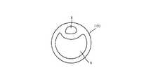
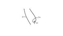
ここで、上述したように、バルーン2による掻き出しを行っても、例えば、図7に示されているように、胆管21内にはその形状が十二指腸側に凸となるような膨らみをもつ袋状になった部分21aが存在し、このような部分21aにはバルーン2が到達できない場合があるため、胆泥や胆石等22が残留してしまう場合がある。例えば、胆泥が残ってしまうと、胆石の再形成につながるため、完全に取り除くことが好ましい。このような場合には、シリンジ等により、ハブ15b、枝管14bおよびメインルーメン9を介して、生理食塩水を噴出口12へ送り込んで、図8に示すように、生理食塩水を噴出口12から噴出させる。 Here, as described above, even if the
噴出口12は、生理食塩水の噴出方向がカテーテルチューブ5の軸心に対して近位端側を指向して例えば45度で斜交するように形成されているため、生理食塩水の噴流は噴出口12から矢印23で示すような角度で噴出され、胆管22の形状が十二指腸側に凸となるようなやや膨らみをもつ袋状になった部分21aの胆泥等22を洗い流し、十二指腸側に流出させることができる。なお、図8では、図示を省略しているが、生理食塩水の噴出による胆泥等22の洗い流しは、バルーン2を膨張させた状態で行う。 The
上述したように、本実施形態のバルーンカテーテル1によれば、生理食塩水はカテーテルチューブ5の軸心A2に対して斜め後方(近位端側)を指向して噴出されるため、胆石や胆泥等を胆管外(十二指腸側)に容易に流出させることができる。従って、胆泥等を確実にかつ容易に除去することができる。また、カテーテルチューブ5の遠位端部7を、近位端部6より細径とすることにより、カテーテルチューブ5の挿入性の悪化を抑制しつつ、噴出口12から噴出される生理食塩水の流量を増やして胆泥等の流出を促進することができる。さらに、カテーテルチューブ5の断面におけるメインルーメン9の形状を、バルーンルーメン8の一部を囲むような略三日月形状とすることにより、カテーテルチューブ5の太径化を抑制しつつ、噴出口12から噴出される生理食塩水の流量を増やして胆泥等の流出を促進することができる。 As described above, according to the
なお、上述した実施形態では、バルーン2として、膨張させた状態においてカテーテルチューブ5の軸心を回転軸としてカテーテルチューブ5の外方に向かって凸の曲線を回転させてなる回転体形状に形成されたものを用いる場合を例に説明したが、図9に示されているように、オフセット型のバルーンを備えるものを用いてもよい。オフセット型のバルーンカテーテル31は、バルーン32を膨張させた状態(図中一点鎖線33’で示す)においてカテーテルチューブ5の軸心に対して偏在する、即ちカテーテルチューブ5に対して特定の方向に偏って膨張するように、接合部34を介して設けたものである。 In the above-described embodiment, the
このようなオフセット型の場合には、噴出口12を、バルーン32が偏在する側に設けることが好ましい。バルーン32が偏在しない側に設けると、バルーン32を膨張させた場合に、カテーテルチューブ5のバルーン32の近位端側の近傍部分のバルーン32が偏在しない側の外面と胆管の内壁とが接触し、または近接するため、噴出口からの生理食塩水の噴出が該胆管の内壁によって妨げられる場合があるので、これを防止するためである。なお、図9において、その他の部分は、図2と実質的に同様であるので、同一の符号を付して、その説明を省略する。 In the case of such an offset type, it is preferable to provide the
上述した実施形態では、バルーンカテーテル1が備えるバルーンは1つとしたが、複数のバルーンを備えていてもよい。 In the above-described embodiment, the
以下、本発明を実施例に基づき、さらに詳細に説明する。 Hereinafter, the present invention will be described in more detail based on examples.
〔実施例1〕
図4および図5に示したルーメン形状(2ルーメンタイプ)で遠位端部7の外径が近位端部6の外径よりも細径とし、太径部と細径部との接続部分をテーパー状としたカテーテルチューブ5を用いた。このカテーテルチューブ5の全長は2000mm、近位端部6側の太径部の外径は2.4mm、近位端部7側の太径部におけるメインルーメン9の断面積は2.01mm2、遠位端側の細径部の外径は1.85mm、遠位端側の細径部におけるメインルーメン9の断面積は1.22mm2、遠位端部7側の細径部の長さは300mmとした。サンプルチューブの材質は、PEBAX7033(米国ARKEMA社商品名)とした。[Example 1]
4 and FIG. 5, the outer diameter of the
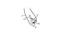
上述のカテーテルチューブ5の壁面に以下の形成方法を用いて噴出口12を形成した。まず、図10に示されているように、カテーテルチューブ5のメインルーメン9内にスタイレット31を挿通し、図11に示されているように、針(例えば、注射針)32を用いてカテーテルチューブ5の壁面に穿孔し、図12に示されているように、外部からメインルーメン9に至って貫通する孔33を形成する。穿孔する前にカテーテルチューブ5のメインルーメン9内にスタイレット31を挿通しておくのは、針32で穿孔する際に、カテーテルチューブ5の内壁等を傷つけないようにするためである。 The
次いで、図13に示されているように、加熱コテ(例えば、半田コテ)34を、斜め後方(近位端部6側)から斜めに挿入して、針32で穿孔した孔33の近位端側を内側へ押し込む。加熱コテ34による加熱温度は、カテーテルチューブ5の材質との関係で、カテーテルチューブ5が溶けない程度の温度、例えば150℃とした。 Next, as shown in FIG. 13, a heating iron (for example, a soldering iron) 34 is inserted obliquely from the rear side (
これにより、図14に示されているように、カテーテルチューブ5の壁面にカテーテルチューブ5の近位端部6側を斜めに指向した噴出口12を形成することができる。加熱コテ34で加工する際にも、カテーテルチューブ5の他の部分を傷つけないようにするため、カテーテルチューブ5内のスタイレット31は挿通したまま加工した。 As a result, as shown in FIG. 14, it is possible to form the
(参考例1)
図15に示したように、バルーンルーメン41a、造影剤ルーメン41bおよびガイドワイヤルーメン41cを有する3ルーメンタイプで、遠位端部の外径が近位端部の外径よりも細径とし、太径部と細径部との接続部分をテーパー状としたカテーテルチューブ41を用いた。このカテーテルチューブ41の全長は2000mm、近位端側の太径部の外径は2.4mm、近位端側の太径部におけるガイドワイヤルーメン41cの断面積は1.61mm2、遠位端側の細径部の外径は1.85mm、遠位端側の細径部におけるガイドワイヤルーメン41cの断面積は0.81mm2、遠位端側の細径部の長さは300mmとした。カテーテルチューブ41の材質は実施例1と同じである。(Reference Example 1)
As shown in FIG. 15, in the three lumen type having a
ガイドワイヤルーメン43cをメインルーメンとして生理食塩水の噴出に用いるものとして、上述のカテーテルチューブ41の壁面に以下の形成方法を用いて噴出口43を形成した。即ち、図16に示されているように、カテーテルチューブ41の壁面の一部を、図中矢印で示すように、外側からメス(カッターナイフ)42で略楕円弧状に抉り取るように切り込んで、図17に示されているように、外側からガイドワイヤルーメン41cに至って貫通する噴出口43を形成した。 As the guide wire lumen 43c used as the main lumen for the ejection of physiological saline, the
(結果)
上述の実施例1および参考例1の方法で噴出口をそれぞれ形成した各カテーテルチューブを、胆管を模擬した透明チューブを立てた状態で該透明チューブの下側から挿入し、透明チューブ内を水で満たした状態で、メインルーメンを介して色水を供給し、噴出口から噴出させて、その様子をそれぞれ観察したところ、参考例1の方法で噴出口を形成したカテーテルチューブでは色水がやや上方に勢い無く噴射され拡散されるのが確認されたのに対して、実施例1の方法で噴出口を形成したカテーテルチューブでは、色水が斜め後方(下方)に勢いよく噴射されることが確認できた。(result)
Each catheter tube in which the spout is formed by the method of Example 1 and Reference Example 1 described above is inserted from the lower side of the transparent tube with the transparent tube imitating the bile duct standing up, and the inside of the transparent tube is filled with water. In the filled state, the colored water is supplied through the main lumen, and the colored water is ejected from the ejection port. When the state is observed, the colored water is slightly above the catheter tube in which the ejection port is formed by the method of Reference Example 1. In contrast, it was confirmed that the colored water was jetted obliquely backward (downward) in the catheter tube in which the jet port was formed by the method of Example 1, whereas it was confirmed that the jet water was jetted and diffused without any force. did it.
〔実施例2〕
仕様の異なる複数のカテーテルチューブからなるサンプルチューブを準備し、略垂直に固定した容量20mLのシリンジに水を満たし、シリンジのピストンに1003.4gの錘を載置して、重力作用によって各サンプルチューブのシリンジ接続用枝管を介して対象ルーメン内に注水し、ピストン先端のガスケットが15mLの位置で計測を開始し、該ガスケットの位置が5mLの位置で計測を終了し、当該10mLの注水に要した時間を基に、1秒間に注水される水量に換算し、換算により得られた値を流量として記録し、該流量の大小を比較する。[Example 2]
Sample tubes consisting of a plurality of catheter tubes with different specifications are prepared, water is filled in a 20 mL syringe fixed substantially vertically, 1003.4 g weight is placed on the syringe piston, and each sample tube is subjected to gravity action. Water is injected into the target lumen through the syringe connecting branch pipe, measurement is started when the gasket at the tip of the piston is 15 mL, and measurement is completed when the gasket is at the 5 mL position. Based on the measured time, it is converted into the amount of water poured into one second, the value obtained by the conversion is recorded as a flow rate, and the magnitudes of the flow rates are compared.
(実施例2−1)
図5に示したルーメン形状(2ルーメンタイプ)で全長に渡り一様な外径を有するサンプルチューブを用いた。このサンプルチューブの全長は2000mm、外径は1.85mm、メインルーメンの断面積は全長に渡って1.22mm2とした。サンプルチューブの主原料はPEBAX7033(米国ARKEMA社商品名)である。(Example 2-1)
A sample tube having a lumen shape (two lumen type) shown in FIG. 5 and a uniform outer diameter over the entire length was used. The total length of this sample tube was 2000 mm, the outer diameter was 1.85 mm, and the cross-sectional area of the main lumen was 1.22 mm2 over the entire length. The main raw material of the sample tube is PEBAX7033 (trade name of ARKEMA, USA).
(実施例2−2)
図5に示したルーメン形状(2ルーメンタイプ)で遠位端部の外径が近位端部の外径よりも細径とし、太径部と細径部との接続部分をテーパー状としたサンプルチューブを用いた。このサンプルチューブの全長は2000mm、近位端側の太径部の外径は2.4mm、近位端側の太径部におけるメインルーメンの断面積は2.01mm2、遠位端側の細径部の外径は1.85mm、遠位端側の細径部におけるメインルーメンの断面積は1.22mm2、遠位端側の細径部の長さは300mmとした。サンプルチューブの主原料は実施例2−1と同じである。(Example 2-2)
In the lumen shape shown in FIG. 5 (two lumen type), the outer diameter of the distal end portion is smaller than the outer diameter of the proximal end portion, and the connecting portion between the large diameter portion and the small diameter portion is tapered. A sample tube was used. The total length of this sample tube is 2000 mm, the outer diameter of the large diameter portion on the proximal end side is 2.4 mm, the cross-sectional area of the main lumen in the large diameter portion on the proximal end side is 2.01 mm2 , and the thin diameter on the distal end side is The outer diameter of the diameter portion was 1.85 mm, the cross-sectional area of the main lumen in the small diameter portion on the distal end side was 1.22 mm2 , and the length of the small diameter portion on the distal end side was 300 mm. The main raw material of the sample tube is the same as in Example 2-1.
(実施例2−3)
遠位端側の細径部の長さを100mmとした以外は、実施例2と同じ仕様のサンプルチューブを用いた。(Example 2-3)
A sample tube having the same specifications as in Example 2 was used except that the length of the small diameter portion on the distal end side was set to 100 mm.
(参考例2−1)
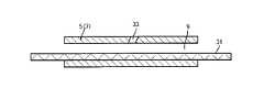
図18に示したように、バルーンルーメン51aおよびメインルーメン51bを有する2ルーメンタイプで、全長に渡り一様な外径を有するサンプルチューブ51を用いた。このサンプルチューブ51の全長は2000mm、外径は2.3mm、メインルーメンの断面積は全長に渡って1.34mm2とした。サンプルチューブの主原料はポリウレタンである。(Reference Example 2-1)
As shown in FIG. 18, a
(参考例2−2)
図示省略する1ルーメンタイプのルーメン形状で全長に渡り一様な外径を有するサンプルチューブを用いた。このサンプルチューブの全長は1950mm、外径は1.8mm、メインルーメンの断面積は全長に渡って0.89mm2とした。サンプルチューブの主原料はPTFEである。(Reference Example 2-2)
A sample tube having a uniform outer diameter over its entire length was used with a 1 lumen type lumen shape not shown. The total length of this sample tube was 1950 mm, the outer diameter was 1.8 mm, and the cross-sectional area of the main lumen was 0.89 mm2 over the entire length. The main raw material of the sample tube is PTFE.
(参考例2−3)
図15に示したように、バルーンルーメン41a、造影剤ルーメン41bおよびガイドワイヤルーメン41cを有する3ルーメンタイプで、遠位端部の外径が近位端部の外径よりも細径とし、太径部と細径部との接続部分をテーパー状としたサンプルチューブ41を用いた。このサンプルチューブ41の全長は2000mm、近位端側の太径部の外径は2.4mm、近位端側の太径部におけるガイドワイヤルーメン41cの断面積は1.61mm2、遠位端側の細径部の外径は1.85mm、遠位端側の細径部におけるガイドワイヤルーメン41cの断面積は0.81mm2、遠位端側の細径部の長さは300mmとした。カテーテルチューブ41の材質は実施例2−1と同じである。ガイドワイヤルーメン41cをメインルーメンとして生理食塩水の噴出に用いるものとした。(Reference Example 2-3)
As shown in FIG. 15, in the three lumen type having a
(結果)
計測結果を図19に示す。図19中、ルーメン断面積は生理食塩水を流通させるメインルーメンの断面積を示し、サンプルがテーパーチューブである場合のルーメン断面積は太径部と細径部との割合から求めた計算値である。また、計測結果に基づく流量(縦軸)とルーメン断面積(横軸)との関係を図20に示す。実施例2−2、実施例2−3と実施例2−1との比較からわかるように、太径部と細径部を有するサンプルチューブ(テーパチューブ)を用いることにより、先端5Fr(フレンチ)程度で胆管挿入性を確保したまま、流量を改善することができる。また、実施例2−2と参考例2−3との比較からわかるように、2ルーメンタイプでかつメインルーメンの断面形状が略三日月型のものを採用することにより、流量を多くすることができる。(result)
The measurement results are shown in FIG. In FIG. 19, the lumen cross-sectional area indicates the cross-sectional area of the main lumen through which physiological saline is circulated, and the lumen cross-sectional area when the sample is a tapered tube is a calculated value obtained from the ratio of the large diameter portion and the small diameter portion. is there. FIG. 20 shows the relationship between the flow rate (vertical axis) and the lumen cross-sectional area (horizontal axis) based on the measurement result. As can be seen from the comparison between Example 2-2, Example 2-3, and Example 2-1, the tip 5Fr (French) is obtained by using a sample tube (taper tube) having a large diameter portion and a small diameter portion. The flow rate can be improved while the bile duct insertion property is secured to some extent. Further, as can be seen from the comparison between Example 2-2 and Reference Example 2-3, the flow rate can be increased by adopting a two-lumen type and a cross-sectional shape of the main lumen that is substantially crescent. .
なお、以上説明した実施形態および実施例は、本発明の理解を容易にするために記載されたものであって、本発明を限定するために記載されたものではない。したがって、上述した実施形態に開示された各要素は、本発明の技術的範囲に属する全ての設計変更や均等物をも含む趣旨である。 The embodiments and examples described above are described for easy understanding of the present invention, and are not described for limiting the present invention. Therefore, each element disclosed in the embodiment described above is intended to include all design changes and equivalents belonging to the technical scope of the present invention.
1,31…バルーンカテーテル
2,32…バルーン
3,33…膨張部
4,34…接合部
5…カテーテルチューブ
6…近位端部
7…遠位端部
8…バルーンルーメン
9…メインルーメン
11…流体導出口
12…噴出口
13…カバー
14a,14b…枝管
15a,15b…ハブ
21…胆管
21a…袋状の部分
22…胆泥等
23…噴出方向
A1…カテーテルチューブの軸心
A2…噴出方向(中心線の方向)DESCRIPTION OF
Claims (8)
Translated fromJapanese前記カテーテルチューブの表面には、前記バルーンの近位端側の近傍に噴出口が形成されており、
前記カテーテルチューブは、前記バルーンを膨張させる第1流体が流通される第1ルーメン、および前記噴出口から噴出させる第2流体が流通される第2ルーメンを有し、
前記噴出口は、前記第2流体の噴出方向が前記カテーテルチューブの軸心に対して近位端側を指向して斜交するように形成されたことを特徴とするバルーンカテーテル。A balloon catheter comprising a catheter tube made of a flexible material and having a distal end and a proximal end, and a balloon made of a stretchable material and attached to the distal end of the catheter tube. And
On the surface of the catheter tube, a spout is formed in the vicinity of the proximal end side of the balloon,
The catheter tube has a first lumen through which a first fluid for inflating the balloon is circulated, and a second lumen through which a second fluid to be ejected from the ejection port is circulated.
The balloon catheter, wherein the ejection port is formed so that the ejection direction of the second fluid is oblique to the proximal end side with respect to the axis of the catheter tube.
Priority Applications (1)
| Application Number | Priority Date | Filing Date | Title |
|---|---|---|---|
| JP2011003749AJP5779885B2 (en) | 2011-01-12 | 2011-01-12 | Balloon catheter |
Applications Claiming Priority (1)
| Application Number | Priority Date | Filing Date | Title |
|---|---|---|---|
| JP2011003749AJP5779885B2 (en) | 2011-01-12 | 2011-01-12 | Balloon catheter |
Publications (2)
| Publication Number | Publication Date |
|---|---|
| JP2012143377Atrue JP2012143377A (en) | 2012-08-02 |
| JP5779885B2 JP5779885B2 (en) | 2015-09-16 |
Family
ID=46787593
Family Applications (1)
| Application Number | Title | Priority Date | Filing Date |
|---|---|---|---|
| JP2011003749AActiveJP5779885B2 (en) | 2011-01-12 | 2011-01-12 | Balloon catheter |
Country Status (1)
| Country | Link |
|---|---|
| JP (1) | JP5779885B2 (en) |
Cited By (3)
| Publication number | Priority date | Publication date | Assignee | Title |
|---|---|---|---|---|
| JP2017517369A (en)* | 2014-07-15 | 2017-06-29 | 中国人民解放軍第二軍医大学 | Deformed balloon type ureteral stone barrier extractor |
| JP2017517368A (en)* | 2014-07-15 | 2017-06-29 | 中国人民解放軍第二軍医大学 | Membrane ureteral stone barrier extractor |
| WO2021186664A1 (en) | 2020-03-19 | 2021-09-23 | 朝日インテック株式会社 | Catheter |
Citations (6)
| Publication number | Priority date | Publication date | Assignee | Title |
|---|---|---|---|---|
| JPH04241877A (en)* | 1991-01-11 | 1992-08-28 | Olympus Optical Co Ltd | Balloon catheter |
| JP3095092U (en)* | 2003-01-06 | 2003-07-18 | 哲 川又 | Catheter with reverse injection hole |
| JP2005185439A (en)* | 2003-12-25 | 2005-07-14 | Satoru Kawamata | Catheter |
| US20080188866A1 (en)* | 2007-02-05 | 2008-08-07 | Wilson-Cook Medical Inc. | Apparatus and methods for removing relatively large and small stones from a body passage |
| JP2008194167A (en)* | 2007-02-09 | 2008-08-28 | Nippon Zeon Co Ltd | Balloon catheter for stone removal |
| JP4379226B2 (en)* | 2004-06-24 | 2009-12-09 | 日本ゼオン株式会社 | Balloon catheter for stone removal |
- 2011
- 2011-01-12JPJP2011003749Apatent/JP5779885B2/enactiveActive
Patent Citations (6)
| Publication number | Priority date | Publication date | Assignee | Title |
|---|---|---|---|---|
| JPH04241877A (en)* | 1991-01-11 | 1992-08-28 | Olympus Optical Co Ltd | Balloon catheter |
| JP3095092U (en)* | 2003-01-06 | 2003-07-18 | 哲 川又 | Catheter with reverse injection hole |
| JP2005185439A (en)* | 2003-12-25 | 2005-07-14 | Satoru Kawamata | Catheter |
| JP4379226B2 (en)* | 2004-06-24 | 2009-12-09 | 日本ゼオン株式会社 | Balloon catheter for stone removal |
| US20080188866A1 (en)* | 2007-02-05 | 2008-08-07 | Wilson-Cook Medical Inc. | Apparatus and methods for removing relatively large and small stones from a body passage |
| JP2008194167A (en)* | 2007-02-09 | 2008-08-28 | Nippon Zeon Co Ltd | Balloon catheter for stone removal |
Cited By (3)
| Publication number | Priority date | Publication date | Assignee | Title |
|---|---|---|---|---|
| JP2017517369A (en)* | 2014-07-15 | 2017-06-29 | 中国人民解放軍第二軍医大学 | Deformed balloon type ureteral stone barrier extractor |
| JP2017517368A (en)* | 2014-07-15 | 2017-06-29 | 中国人民解放軍第二軍医大学 | Membrane ureteral stone barrier extractor |
| WO2021186664A1 (en) | 2020-03-19 | 2021-09-23 | 朝日インテック株式会社 | Catheter |
Also Published As
| Publication number | Publication date |
|---|---|
| JP5779885B2 (en) | 2015-09-16 |
Similar Documents
| Publication | Publication Date | Title |
|---|---|---|
| CN107206213B (en) | Treatment instrument for endoscope | |
| CN109350178B (en) | Thrombectomy Device | |
| JP7280996B2 (en) | medical device | |
| CN1203811C (en) | Embolectomy catheters and methods for treating stroke and other small vessel thromboembolic disorders | |
| JP4422472B2 (en) | Submucosa peeling treatment device and system | |
| KR101317434B1 (en) | Catheter for removing thrombus in blood vessel | |
| US20130158511A1 (en) | Thrombus removal apparatus and method | |
| CN108289690A (en) | Treatment tool for endoscope | |
| KR101481887B1 (en) | Catheter and method for inserting catheter | |
| JPH01145074A (en) | Balloon catheter | |
| JPH11276594A (en) | Catheter | |
| US10850075B2 (en) | Balloon catheter and manufacturing method of elongated member for balloon catheter | |
| JP5779885B2 (en) | Balloon catheter | |
| JP2017517369A (en) | Deformed balloon type ureteral stone barrier extractor | |
| JP5135816B2 (en) | Balloon catheter for stone removal | |
| JP6519368B2 (en) | Treatment tool for endoscope and method of manufacturing the same | |
| JP2017113271A (en) | Endoscopic treatment instrument | |
| JP2008194167A (en) | Balloon catheter for stone removal | |
| JP2016198355A (en) | Endoscopic treatment tool | |
| JP4379226B2 (en) | Balloon catheter for stone removal | |
| JP7205048B2 (en) | Manufacturing method of balloon catheter for removal of foreign body | |
| JPWO2021062088A5 (en) | ||
| JP6162932B2 (en) | Balloon catheter and balloon catheter manufacturing method | |
| JP5903875B2 (en) | Endoscopic needle | |
| JP6780328B2 (en) | Balloon catheter for stone removal |
Legal Events
| Date | Code | Title | Description |
|---|---|---|---|
| A621 | Written request for application examination | Free format text:JAPANESE INTERMEDIATE CODE: A621 Effective date:20130913 | |
| A131 | Notification of reasons for refusal | Free format text:JAPANESE INTERMEDIATE CODE: A131 Effective date:20140610 | |
| A977 | Report on retrieval | Free format text:JAPANESE INTERMEDIATE CODE: A971007 Effective date:20140613 | |
| A521 | Request for written amendment filed | Free format text:JAPANESE INTERMEDIATE CODE: A523 Effective date:20140731 | |
| A02 | Decision of refusal | Free format text:JAPANESE INTERMEDIATE CODE: A02 Effective date:20150113 | |
| A521 | Request for written amendment filed | Free format text:JAPANESE INTERMEDIATE CODE: A523 Effective date:20150413 | |
| A911 | Transfer to examiner for re-examination before appeal (zenchi) | Free format text:JAPANESE INTERMEDIATE CODE: A911 Effective date:20150421 | |
| TRDD | Decision of grant or rejection written | ||
| A01 | Written decision to grant a patent or to grant a registration (utility model) | Free format text:JAPANESE INTERMEDIATE CODE: A01 Effective date:20150616 | |
| A61 | First payment of annual fees (during grant procedure) | Free format text:JAPANESE INTERMEDIATE CODE: A61 Effective date:20150629 | |
| R150 | Certificate of patent or registration of utility model | Ref document number:5779885 Country of ref document:JP Free format text:JAPANESE INTERMEDIATE CODE: R150 | |
| R250 | Receipt of annual fees | Free format text:JAPANESE INTERMEDIATE CODE: R250 | |
| R250 | Receipt of annual fees | Free format text:JAPANESE INTERMEDIATE CODE: R250 | |
| R250 | Receipt of annual fees | Free format text:JAPANESE INTERMEDIATE CODE: R250 | |
| R250 | Receipt of annual fees | Free format text:JAPANESE INTERMEDIATE CODE: R250 | |
| R250 | Receipt of annual fees | Free format text:JAPANESE INTERMEDIATE CODE: R250 | |
| R250 | Receipt of annual fees | Free format text:JAPANESE INTERMEDIATE CODE: R250 | |
| R250 | Receipt of annual fees | Free format text:JAPANESE INTERMEDIATE CODE: R250 | |
| R250 | Receipt of annual fees | Free format text:JAPANESE INTERMEDIATE CODE: R250 |