JP2012143146A - Wireless power transmission apparatus and wireless power transmission system thereof - Google Patents
Wireless power transmission apparatus and wireless power transmission system thereofDownload PDFInfo
- Publication number
- JP2012143146A JP2012143146AJP2011288196AJP2011288196AJP2012143146AJP 2012143146 AJP2012143146 AJP 2012143146AJP 2011288196 AJP2011288196 AJP 2011288196AJP 2011288196 AJP2011288196 AJP 2011288196AJP 2012143146 AJP2012143146 AJP 2012143146A
- Authority
- JP
- Japan
- Prior art keywords
- wireless power
- power transmission
- transmission device
- magnetic field
- conductive wire
- Prior art date
- Legal status (The legal status is an assumption and is not a legal conclusion. Google has not performed a legal analysis and makes no representation as to the accuracy of the status listed.)
- Ceased
Links
Images


Classifications
- H—ELECTRICITY
- H04—ELECTRIC COMMUNICATION TECHNIQUE
- H04B—TRANSMISSION
- H04B5/00—Near-field transmission systems, e.g. inductive or capacitive transmission systems
- H04B5/70—Near-field transmission systems, e.g. inductive or capacitive transmission systems specially adapted for specific purposes
- H04B5/79—Near-field transmission systems, e.g. inductive or capacitive transmission systems specially adapted for specific purposes for data transfer in combination with power transfer
- H—ELECTRICITY
- H02—GENERATION; CONVERSION OR DISTRIBUTION OF ELECTRIC POWER
- H02J—CIRCUIT ARRANGEMENTS OR SYSTEMS FOR SUPPLYING OR DISTRIBUTING ELECTRIC POWER; SYSTEMS FOR STORING ELECTRIC ENERGY
- H02J50/00—Circuit arrangements or systems for wireless supply or distribution of electric power
- H02J50/10—Circuit arrangements or systems for wireless supply or distribution of electric power using inductive coupling
- H02J50/12—Circuit arrangements or systems for wireless supply or distribution of electric power using inductive coupling of the resonant type
- H—ELECTRICITY
- H02—GENERATION; CONVERSION OR DISTRIBUTION OF ELECTRIC POWER
- H02J—CIRCUIT ARRANGEMENTS OR SYSTEMS FOR SUPPLYING OR DISTRIBUTING ELECTRIC POWER; SYSTEMS FOR STORING ELECTRIC ENERGY
- H02J50/00—Circuit arrangements or systems for wireless supply or distribution of electric power
- H02J50/40—Circuit arrangements or systems for wireless supply or distribution of electric power using two or more transmitting or receiving devices
- H—ELECTRICITY
- H02—GENERATION; CONVERSION OR DISTRIBUTION OF ELECTRIC POWER
- H02J—CIRCUIT ARRANGEMENTS OR SYSTEMS FOR SUPPLYING OR DISTRIBUTING ELECTRIC POWER; SYSTEMS FOR STORING ELECTRIC ENERGY
- H02J50/00—Circuit arrangements or systems for wireless supply or distribution of electric power
- H02J50/70—Circuit arrangements or systems for wireless supply or distribution of electric power involving the reduction of electric, magnetic or electromagnetic leakage fields
- H—ELECTRICITY
- H02—GENERATION; CONVERSION OR DISTRIBUTION OF ELECTRIC POWER
- H02J—CIRCUIT ARRANGEMENTS OR SYSTEMS FOR SUPPLYING OR DISTRIBUTING ELECTRIC POWER; SYSTEMS FOR STORING ELECTRIC ENERGY
- H02J7/00—Circuit arrangements for charging or depolarising batteries or for supplying loads from batteries
- H02J7/0042—Circuit arrangements for charging or depolarising batteries or for supplying loads from batteries characterised by the mechanical construction
- H02J7/0044—Circuit arrangements for charging or depolarising batteries or for supplying loads from batteries characterised by the mechanical construction specially adapted for holding portable devices containing batteries
- H—ELECTRICITY
- H04—ELECTRIC COMMUNICATION TECHNIQUE
- H04B—TRANSMISSION
- H04B5/00—Near-field transmission systems, e.g. inductive or capacitive transmission systems
- H04B5/20—Near-field transmission systems, e.g. inductive or capacitive transmission systems characterised by the transmission technique; characterised by the transmission medium
- H04B5/24—Inductive coupling
- H04B5/26—Inductive coupling using coils
- H04B5/266—One coil at each side, e.g. with primary and secondary coils
Landscapes
- Engineering & Computer Science (AREA)
- Computer Networks & Wireless Communication (AREA)
- Power Engineering (AREA)
- Physics & Mathematics (AREA)
- Electromagnetism (AREA)
- Signal Processing (AREA)
- Charge And Discharge Circuits For Batteries Or The Like (AREA)
- Transmitters (AREA)
- Near-Field Transmission Systems (AREA)
Abstract
Translated fromJapaneseDescription
Translated fromJapanese本発明は、無線電力送信装置及びその無線電力送信システムに関し、より詳細には、共振器を用いて無線で外部装置を充電する無線電力送信装置及びその無線電力送信システムに関する。 The present invention relates to a wireless power transmission device and a wireless power transmission system thereof, and more particularly to a wireless power transmission device that wirelessly charges an external device using a resonator and the wireless power transmission system thereof.
最近は、ディスプレイ装置が2D映像だけでなく、立体感のある3D映像も提供している。特に、立体感のある3D映像を視聴するためのディスプレイ装置としては、特殊眼鏡を使用する眼鏡式と、特殊眼鏡を使用しない非眼鏡式とがある。 Recently, the display device provides not only 2D video but also 3D video with a stereoscopic effect. In particular, display devices for viewing stereoscopic 3D images include a spectacle type using special glasses and a non-glass type using no special glasses.
特に、立体感のある3D映像を視聴するためには、シャッターグラス方式のディスプレイ装置では、ディスプレイ装置から送信された同期信号によって3Dメガネの左眼グラスと右眼グラスとが交互にオン/オフされなければならない。即ち、3D映像を視聴するためには、3Dメガネを駆動するための電力供給が必要である。 In particular, in order to view 3D images with a stereoscopic effect, in the shutter glass type display device, the left eye glass and the right eye glass of the 3D glasses are alternately turned on / off by a synchronization signal transmitted from the display device. There must be. That is, in order to view 3D video, it is necessary to supply power for driving the 3D glasses.
この時、3Dメガネの電力を供給するための方法には、使い捨てのバッテリー式と充電式とが存在する。使い捨てのバッテリー式の場合、毎回バッテリーを取り替えなければならないため、費用がかさむなど不都合があった。なお、充電式の場合、ケーブルを用いて3Dメガネを充電しなければならないため、常にケーブルを持ち歩かなければならず、見た目上にも望ましくないという短所があった。 At this time, there are a disposable battery type and a rechargeable type of method for supplying power to the 3D glasses. In the case of the disposable battery type, since the battery has to be replaced every time, there is a problem such as high cost. In the case of the rechargeable type, since the 3D glasses must be charged using a cable, the cable must always be carried around, which is not desirable in appearance.
従って、より簡単かつ効率的に3Dメガネを充電できる方策への模索が求められる。 Accordingly, there is a demand for a method for charging 3D glasses more easily and efficiently.
そこで、本発明は、上記問題に鑑みてなされたものであり、本発明の目的とするところは、より簡単かつ効率的に3Dメガネを充電できる無線電力送信装置及びその無線電力送信システムを提供することにある。 Therefore, the present invention has been made in view of the above problems, and an object of the present invention is to provide a wireless power transmission apparatus and a wireless power transmission system for charging 3D glasses more easily and efficiently. There is.
前記目的を達成するための本発明の一実施形態に係る無線電力送信装置において、RFアンプ部(RF Amplifier Block)と、送信共振部を含むメインボディと、前記メインボディの側面に位置した支持台とを含み、前記送信共振部は送信導電性ワイヤループ(Conductive Wire Loop)を用いて前記支持台上に位置した第1無線電力受信装置に水平磁気フィールドを提供し、前記第1無線電力受信装置はループ面が前記水平磁気フィールドと垂直方向の第1受信導電性ワイヤループを含む。 In order to achieve the above object, in a wireless power transmission device according to an embodiment of the present invention, an RF amplifier block (RF Amplifier Block), a main body including a transmission resonance unit, and a support base positioned on a side surface of the main body And the transmission resonance unit provides a horizontal magnetic field to the first wireless power receiving device located on the support using a conductive wire loop, and the first wireless power receiving device. Includes a first receiving conductive wire loop whose loop surface is perpendicular to the horizontal magnetic field.
なお、前記送信共振部は前記送信導電性ワイヤループを用いて、前記メインボディ上に位置した第2無線電力受信装置に垂直磁気フィールドを提供し、前記第2無線電力受信装置はループ面が前記垂直磁気フィールドと垂直方向の第2受信導電性ワイヤループを含んでよい。 The transmission resonance unit uses the transmission conductive wire loop to provide a perpendicular magnetic field to a second wireless power receiving device located on the main body, and the second wireless power receiving device has a loop surface that has the loop surface. A perpendicular magnetic field and a perpendicular second receiving conductive wire loop may be included.
そして、前記メインボディは、シリンダ型であってよい。 The main body may be a cylinder type.
なお、前記支持台は、円形板であってよい。 The support base may be a circular plate.
そして、前記送信導電性ワイヤループは、シリンダ型であってよい。 The transmission conductive wire loop may be a cylinder type.
なお、前記送信導電性ワイヤループは、ワイヤループが円形で曲がることによりシリンダ型に形成されてよい。 The transmission conductive wire loop may be formed in a cylinder shape by bending the wire loop in a circular shape.
そして、共振キャパシタ及び前記送信導電性ワイヤループに電流を誘導するフィーダ導電性ワイヤループ(Feeder Conductive Wire Loop)を更に含んでよい。 The feeder conductive wire loop may further include a resonant capacitor and a feeder conductive wire loop that induces a current in the transmission conductive wire loop.
なお、前記無線電力送信装置は、Root(Qs*Qd)(Qsは無線電力送信装置のQ値、Qdは無線電力受信装置のQ値)に比例する伝送効率を持ってよい。 The wireless power transmission device may have a transmission efficiency proportional to Root (Qs * Qd) (Qs is a Q value of the wireless power transmission device and Qd is a Q value of the wireless power reception device).
そして、前記送信共振部は、1MHzないし30MHzの共振周波数を持ってよい。 The transmission resonance unit may have a resonance frequency of 1 MHz to 30 MHz.
なお、前記送信共振部は、可変可能な共振周波数を持ってよい。 Note that the transmission resonance unit may have a variable resonance frequency.
そして、前記RFアンプ部は、可変可能な動作周波数(Operating Frequency)を持ってよい。 The RF amplifier unit may have a variable operating frequency.
なお、前記送信導電性ワイヤループは、前記メインボディ内部の周縁に接してよい。 The transmission conductive wire loop may be in contact with a peripheral edge inside the main body.
そして、前記送信導電性ワイヤループは、垂直磁気フィールド及び水平磁気フィールドを同時に生成してよい。 The transmission conductive wire loop may simultaneously generate a vertical magnetic field and a horizontal magnetic field.
なお、前記無線電力送信装置は、前記RFアンプ部と前記送信共振部との間に遮蔽剤を更に含んでよい。 The wireless power transmission device may further include a shielding agent between the RF amplifier unit and the transmission resonance unit.
そして、前記遮蔽剤は、フェライトシート(Ferrite Sheet)であってよい。 The shielding agent may be a ferrite sheet.
なお、前記RFアンプ部は、シールドケース(Shield Case)で囲い込まれてよい。 The RF amplifier unit may be enclosed by a shield case.
そして、前記シールドケースは、はんだメッキであってよい。 The shield case may be solder plating.
なお、前記無線電力送信装置は、前記RFアンプ部と前記送信共振部との間に予め設定された離間距離を持つように形成されてよい。 The wireless power transmission device may be formed so as to have a preset separation distance between the RF amplifier unit and the transmission resonance unit.
そして、前記第1無線電力受信装置は、3Dメガネ、携帯電話、及びリモコンのうちいずれか一つであってよい。 The first wireless power receiver may be any one of 3D glasses, a mobile phone, and a remote controller.
そして、前記第2無線電力受信装置は、3Dメガネ、携帯電話、及びリモコンのうちいずれか一つであってよい。 The second wireless power receiver may be any one of 3D glasses, a mobile phone, and a remote controller.
一方、上述の目的を達成するために案出された本発明の一実施形態に係る無線電力送信システムは、垂直方向の磁気フィールドと水平方向の磁気フィールドとを同時に生成する無線電力送信装置と、ループ面が前記水平方向の磁気フィールドと垂直方向の第1受信導電性ワイヤループを持つ第1無線電力受信装置と、ループ面が前記水平方向の磁気フィールドと垂直方向の第2受信導電性ワイヤループを持つ第2無線電力受信装置とを含んでよい。 Meanwhile, a wireless power transmission system according to an embodiment of the present invention devised to achieve the above object includes a wireless power transmission device that simultaneously generates a vertical magnetic field and a horizontal magnetic field; A first wireless power receiver having a loop surface with the first magnetic field in the vertical direction and a first reception conductive wire loop in the vertical direction; and a second reception conductive wire loop with the loop surface in the direction perpendicular to the horizontal magnetic field. And a second wireless power receiving apparatus.
そして、前記無線電力送信装置は、送信共振器を含むメインボディと、前記メインボディの側面に位置した支持台とを含み、前記送信共振器は、前記支持台上に位置した前記第1無線電力受信装置に前記水平方向の磁気フィールドを提供してよい。 The wireless power transmission device includes a main body including a transmission resonator and a support base positioned on a side surface of the main body, and the transmission resonator is the first wireless power positioned on the support base. The horizontal magnetic field may be provided to a receiving device.
なお、前記送信共振部は、前記メインボディ上に位置した前記第2無線電力受信装置に前記垂直方向の磁気フィールドを提供してよい。 The transmission resonance unit may provide the vertical magnetic field to the second wireless power reception device located on the main body.
そして、前記無線電力送信装置は、シリンダ型の送信導電性ワイヤループを含んでよい。 The wireless power transmission device may include a cylinder-type transmission conductive wire loop.
なお、前記無線電力送信装置は、ワイヤループが円形で曲がることによりシリンダ型に形成される送信導電性ワイヤループを含んでよい。 The wireless power transmission device may include a transmission conductive wire loop formed in a cylinder shape by bending the wire loop in a circular shape.
そして、前記無線電力送信装置は、共振キャパシタ及び前記送信導電性ワイヤループに電流を誘導するフィーダ導電性ワイヤループ(Feeder Conductive Wire Loop)を更に含んでよい。 The wireless power transmission device may further include a feeder conductive wire loop that induces a current in a resonance capacitor and the transmission conductive wire loop.
なお、前記無線電力送信システムは、Root(Qs*Qd)(Qsは無線電力送信装置のQ値、Qdは無線電力受信装置のQ値)に比例する伝送効率を持ってよい。 The wireless power transmission system may have a transmission efficiency proportional to Root (Qs * Qd) (Qs is the Q value of the wireless power transmission device, and Qd is the Q value of the wireless power reception device).
そして、前記無線電力送信装置は、1MHzないし30MHzの共振周波数を持ってよい。 The wireless power transmission device may have a resonance frequency of 1 MHz to 30 MHz.
なお、前記無線電力送信装置は、可変可能な共振周波数を持ってよい。 The wireless power transmission apparatus may have a variable resonance frequency.
そして、前記無線電力送信装置は、可変可能な動作周波数(Operating Frequency)を持つRFアンプ部と含んでよい。 The wireless power transmission apparatus may include an RF amplifier unit having a variable operating frequency.
なお、前記無線電力送信装置は、RFアンプ部と、送信導電性ワイヤループと、前記RFアンプ部と前記送信導電性ワイヤループとの間に遮蔽剤を更に含んでよい。 The wireless power transmission device may further include a shielding agent between the RF amplifier unit, the transmission conductive wire loop, and the RF amplifier unit and the transmission conductive wire loop.
そして、前記遮蔽剤は、フェライトシート(Ferrite Sheet)であってよい。 The shielding agent may be a ferrite sheet.
なお、前記RFアンプ部は、シールドケース(Shield Case)で囲い込まれてよい。 The RF amplifier unit may be enclosed by a shield case.
そして、前記シールドケースは、はんだメッキであってよい。 The shield case may be solder plating.
なお、前記無線電力送信装置は、前記RFアンプ部と前記送信共振部との間に予め設定された離間距離を持つように形成されてよい。 The wireless power transmission device may be formed so as to have a preset separation distance between the RF amplifier unit and the transmission resonance unit.
そして、前記第1無線電力受信装置は、3Dメガネ、携帯電話、及びリモコンのうちいずれか一つであってよい。 The first wireless power receiver may be any one of 3D glasses, a mobile phone, and a remote controller.
そして、前記第2無線電力受信装置は、3Dメガネ、携帯電話、及びリモコンのうちいずれか一つであってよい。 The second wireless power receiver may be any one of 3D glasses, a mobile phone, and a remote controller.
そして、前記無線電力送信装置は、前記第1無線電力受信装置を収納するための円形支持台を含んでよい。 The wireless power transmission device may include a circular support base for housing the first wireless power reception device.
上述のように本発明によると、3Dメガネを簡単かつ効率的に充電できるようになる。 As described above, according to the present invention, 3D glasses can be easily and efficiently charged.
以上説明したように本発明によれば、一つの無線電力送信装置を通じて複数の無線電力受信装置(3Dメガネやリモコンや携帯電話など)を充電することにより、ユーザはより簡単かつ効率的に各種機器を充電できるようになる。 As described above, according to the present invention, by charging a plurality of wireless power receiving devices (such as 3D glasses, a remote controller, and a mobile phone) through one wireless power transmitting device, the user can easily and efficiently use various devices. Will be able to charge.
以下に添付図面を参照しながら、本発明の好適な実施の形態について詳細に説明する。 Exemplary embodiments of the present invention will be described below in detail with reference to the accompanying drawings.
図1は、本発明の一実施形態に係る無線電力送信システムのブロック図を示す図である。特に、本発明の一実施形態に係る無線電力送信システムは、無線電力送信装置100と、第1無線電力受信装置200及び第2無線電力受信装置300を含む。 FIG. 1 is a block diagram of a wireless power transmission system according to an embodiment of the present invention. In particular, a wireless power transmission system according to an embodiment of the present invention includes a wireless
無線電力送信装置100は、送信共振器(図2A及び図2Bを参照して後述する)を用いて第1無線電力受信装置200及び第2無線電力受信装置300に無線で磁気的エネルギーを送信する。 The wireless
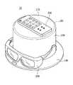
具体的に、無線電力送信装置100は、シリンダ型に形成された送信共振器を用いて、地表面に対して水平方向の磁気フィールドと垂直方向の磁気フィールドを生成する。そして、無線電力送信装置100は、水平方向の磁気フィールドを用いて、無線電力送信装置100の支持台140に置かれた第1無線電力受信装置200を充電し、垂直方向の磁気フィールドを用いて、無線電力送信装置100のメインボディ130の上面170に置かれた第2無線電力受信装置300を充電する。 Specifically, the wireless
特に、図1に示すように、無線電力送信装置100は水平方向の磁気フィールド及び垂直方向の磁気フィールドを同時に生成するために、送信共振部を含むシリンダ型のメインボディ130及びシリンダ型の送信導電性ワイヤループ(Conductive Wire Loop)を含む。 In particular, as shown in FIG. 1, the wireless
第1無線電力受信装置200は、受信共振器(図2A及び図2Cを参照して後述する)を用いて無線電力送信装置100から伝送される磁気的エネルギーを用いて電源を充電する。具体的に、第1無線電力受信装置200は、無線電力送信装置100の送信共振器から生成された水平方向の磁気フィールドを用いて電源を充電する。この時、第1無線電力受信装置200の受信共振器は、ループ面が水平方向の磁気フィールドと垂直の第1受信導電性ワイヤループとを含む。ここで、ループ面とは、受信導電性ワイヤループがなしている面をいう。 The first
一方、第1無線電力受信装置200は3Dメガネであってよいが、これに限定されることなく、リモコン又は携帯電話のような装置にも適用可能である。例えば、リモコン又は携帯電話を支持台140に載せておく場合、リモコン又は携帯電話の受信導電性ワイヤループのループ面が水平方向の磁気フィールドと垂直になるように置くと、リモコン又は携帯電話を充電できるようになる。 On the other hand, the first wireless
第2無線電力受信装置300は、受信共振器を用いて無線電力送信装置100から伝送される磁気的エネルギーを用いて電源を充電する。具体的に、第2無線電力受信装置300は、無線電力送信装置100の送信共振器から生成された垂直方向の磁気フィールドを用いて電源を充電する。この時、第2無線電力受信装置300の受信共振器は、ループ面が垂直方向の磁気フィールドと垂直の第2受信導電性ワイヤループを含む。 The second
一方、第2無線電力受信装置300はリモコン又は携帯電話であってよいが、これに限定されることなく、3Dメガネのような装置にも適用可能である。例えば、3Dメガネをメインボディの上面に載せておく場合、3Dメガネの受信導電性ワイヤループのループ面が垂直方向の磁気フィールドと垂直になるように置くと、3Dメガネを充電できるようになる。 On the other hand, the second wireless
特に、無線電力送信装置100と、第1無線電力受信装置200及び第2無線電力受信装置300は、高い共振品質係数(Q−factor)を持つことができる。これは、エネルギー受信効率が無線電力送信装置100及び無線電力受信装置200、300のQ−factorが大きくなればなるほど、大きくなるためである。特に、無線電力送信システム100は、Root(Qs*Qd)(Qsは無線電力送信装置のQ値、Qdは無線電力受信装置のQ値)に比例する伝送効率を持ってよい。なお、無線電力送信装置100及び無線電力受信装置200、300が高いQ−factorを持つために、ループ(Loop)型の共振器を持ち、高品質低損失(即ち、導線の抵抗が低い)キャパシタで構成されてよい。なお、金属物が近くにある場合、Q値が急激に低くなるため、無線電力送信装置100及び無線電力受信装置200、300は遮蔽構造を持ってよい。 In particular, the wireless
以下では、図2Aないし図2Cを参照しながら、無線電力送信システム100の無線充電方法について説明する。 Hereinafter, a wireless charging method of the wireless
上述のように、無線電力送信システム100は、無線電力送信装置100及び第1無線電力受信装置200を含む。この時、無線電力送信装置100はRFアンプ部(RF Amplifier Block)110及び送信共振部120を含む。 As described above, the wireless
RFアンプ部110は、電源部(図示せず)から伝送されたDC電圧を用いて高周波のAC波形を生成して磁場を形成させて共振周波数に集中した磁場を形成する。そして、RFアンプ部110は、高周波(MHz級)のAC波形を生成して送信共振部120に励磁させる。この時、RFアンプ部110は、特定の動作周波数(Operating Frequency)を持ち、特定の動作周波数は可変可能である。 The
なお、RFアンプ部110の特定の動作周波数は、送信共振器120から発生する磁場の共振周波数と同じであり、RFアンプ部110の動作周波数は13.95MHzであってよい。しかし、これは一実施形態に過ぎず、RFアンプ部110の動作周波数は1〜30MHzの範囲内の周波数であってよい。1〜30MHzの範囲の動作周波数を持つ場合、共振器のサイズが小さくなってよく、高いQ−factorを持ってよく、動作周波数の範囲があまりにも大きすぎたり小さすぎたりする場合、パワー素子の限界により伝送効率が急減するため効率的ではない。 The specific operating frequency of the
図2Bに示すような送信共振部120は、第1無線電力受信装置200に送信する磁気的エネルギーを生成する。具体的に、送信共振部120はフィーダ導電性ワイヤループ126と、送信導電性ワイヤループ125及び共振キャパシタ127を含む。 The
フィーダ導電性ワイヤループ126は、インダクティブカップリング(Inductive Coupling)の形態で接続された送信導電性ワイヤループ125に電流を誘導し、共振周波数に集中した磁場の生成を誘導する。この時、共振周波数は上述のように、13.95MHzであってよい。しかし、これは一実施形態に過ぎず、RFアンプ部110の動作周波数は1〜30MHzの範囲内の周波数であってよい。 The feeder conductive wire loop 126 induces a current in the transmission
送信導電性ワイヤループ125は、共振周波数に集中した磁場を生成する。この時、送信導電性ワイヤループ125は地表面と水平方向の磁気フィールド及び垂直方向の磁気フィールドを生成するために、シリンダ型であってよい。特に、送信導電性ワイヤループ125はワイヤループが円形に曲がることにより形成されてよい。特に、送信導電性ワイヤループ125はメインボディ130の内部の周縁に接して生成されてよい。送信導電性ワイヤループ125が生成する磁場については、図4Aないし図4Cを参照しながら後述する。 The transmit
なお、送信共振部120は、LC共振器として、共振キャパシタとインダクタの値を変化させて共振周波数を変更させてよい。 Note that the
なお、無線電力送信装置100は、金属物が近くにある際、Q−factorが急激に低くなるEddy Field現象を防止するために遮蔽剤を含んでよい。無線電力送信装置100の遮蔽剤については、図5を参照して説明する。 Note that the wireless
上述のように、無線電力送信装置100は、送信共振部から生成された磁気的エネルギーを無線で無線電力受信装置200、300に伝送する。 As described above, the wireless
なお、無線電力受信装置200は、図2に示すように、受信共振部210と、整流部220と、DC/DC変換部230及び充電部240を含む。 As illustrated in FIG. 2, the wireless
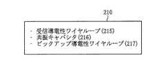
図2Cに示すような受信共振部210は、特定周波数に集中した磁気的エネルギーを受信する。具体的に、受信共振部210は、無線電力受信装置200(例えば、3Dメガネ)の縁に形成された受信導電性ワイヤループ215と、受信導電性ワイヤループに接続された共振キャパシタ216及びピックアップ導電性ワイヤループ217を含む。特に、無線電力受信装置200が3Dメガネである場合、受信導電性ワイヤループ215は、3Dメガネのメガネフレームに形成されてよく、無線電力受信装置200がリモコン又は携帯電話である場合、受信導電性ワイヤループ215は、リモコン又は携帯電話の縁に形成されてよい。しかし、これは一実施形態に過ぎず、3Dメガネ、リモコン及び携帯電話の別の位置に受信導電性ワイヤループ215が形成されてよい。この時、受信導電性ワイヤループ215は、PCB又はフィルムPCBを用いて形成されてよい。 The
受信導電性ワイヤループ215は、送信共振部120から生成された共振周波数の磁場により、受信共振部210がアクティベーションされることにより、電流が流れるようになる。この時、受信導電性ワイヤループ215は、送信共振部220から生成された水平方向の磁気フィールド又は垂直方向の磁気フィールドと垂直に置かれることにより、アクティベーションされる。具体的に、無線電力受信装置200が支持台140に置かれた場合、受信導電性ワイヤループ215は送信共振部120から発生する水平方向の磁気フィールドと垂直になるように置かれることによりアクティベーションされる。なお、無線電力受信装置200がメインボディ130の上面170に置かれた場合、受信導電性ワイヤループ215は送信共振部120から発生する垂直方向の磁気フィールドと垂直になるように置かれることによりアクティベーションされる。 The reception conductive wire loop 215 causes a current to flow when the
ピックアップ導電性ワイヤループ217は、受信導電性ワイヤループ215から発生した電流が誘導されるようにし、整流部220に提供する。 The pickup conductive wire loop 217 induces a current generated from the reception conductive wire loop 215 and provides it to the rectifying
整流部220は、ピックアップ導電性ワイヤループから伝送されたAC電圧をDC電圧に整流する。この時、整流部220は4つのダイオードを備えるブリッジダイオードとフィルタリング役割を担うキャパシタを備えてよい。しかし、これは一実施形態に過ぎず、AC入力をDC入力に整流する別の回路を用いて実現してよい。 The rectifying
整流部220によって整流されたDC電圧が一定の電圧を維持していないため、DC/DC変換部230は整流されたDC電圧が一定の電圧に維持されるようにDC電圧を調整する。 Since the DC voltage rectified by the
充電部240は、前記整流された一定電圧をバッテリに充電する。特に、充電部240は整流部220の出力電圧を用いて充電動作を制御する充電IC及びバッテリを含んでよい。 The charging
以下では、図3及び図4を参照しながら無線電力送信装置100をより具体的に説明する。 Hereinafter, the wireless
図3は、本発明の一実施形態に係る無線電力送信装置100の外部構成を示す図である。図3に示すように、無線電力送信装置100はメインボディ130と、支持台140と、表示部150及びボタン部160を含む。 FIG. 3 is a diagram illustrating an external configuration of the wireless
メインボディ130は、無線電力送信装置100の送信共振部120を収容する。特に、図3に示すように、シリンダ型の送信共振部120を収容するための、メインボディ130はシリンダ型である。そして、メインボディ130は第2無線電力受信装置300が置かれるように、平らな上面170を含む。従って、第2無線電力受信装置300がメインボディ130の上面に置かれることにより、垂直方向の磁気フィールドにより無線充電が可能となる。 The
支持台140は、メインボディ130の側面に形成される。特に、図3に示すように、支持台140の周縁には無線電力送信装置100の電源状態などを報知する表示部150を含む。この時、支持台140は第1無線電力受信装置200が収納できるように、円形板の形態で実現されてよい。従って、第1無線電力受信装置200が支持台140の上に置かれることにより、水平方向の磁気フィールドにより無線充電が可能となる。 The
なお、無線電力送信装置100は、無線電力受信装置200、300を充電するか否かに応じて、電源を制御するための電源ボタン部160を含む。 Note that the wireless
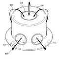
図4Aないし図4Cは、本発明の一実施形態に係る無線電力送信装置200から生成された磁場を示す図である。 4A to 4C are diagrams illustrating a magnetic field generated from the wireless
図4Aに示すように、シリンダ型の無線電力送信装置100は、垂直方向の磁気フィールド430及び水平方向の磁気フィールド440を発生する。従って、垂直方向の磁気フィールド430は第2無線電力受信装置300のループ面410と垂直となることにより、第2無線電力受信装置300を充電する。なお、水平方向の磁気フィールド440は第1無線電力受信装置200のループ面420と垂直となることにより、第1無線電力受信装置200を充電する。 As shown in FIG. 4A, the cylinder-type wireless
なお、図4Bは、図4Aに示された無線電力送信装置100の内部に含まれた送信共振部120を示す図である。上述のように、無線電力送信装置100が垂直方向の磁気フィールド430と水平方向の磁気フィールドの磁気フィールド440を生成するために、送信共振部120はシリンダ型である。 4B is a diagram illustrating the
図4Cは、シリンダ型の送信共振器120の磁気フィールドを示す図である。図4Cに示すように、シリンダ型の送信共振器120の磁気フィールドは上面と側面の垂直方向に形成されることがわかる。 FIG. 4C is a diagram illustrating a magnetic field of the cylinder-
一方、無線電力送信装置100が金属テーブルに置かれる場合、金属テーブルにより送信共振器120の共振周波数が移動されたり、Q−factorが低下する現象(Eddy Current効果)が発生する。従って、金属テーブルにより無線電力送信装置100の充電性能が減少する現象を防止するために、無線電力送信装置100は遮蔽構造を含んでよい。以下では、図5を参照しながら無線電力送信装置100の遮蔽構造について説明する。 On the other hand, when the wireless
図5は、本発明の一実施形態に係る遮蔽構造が含まれた無線電力送信装置100を示す図である。図5に示されたRFアンプ部110及び送信共振部120についての説明は図2での説明と同様である。 FIG. 5 is a diagram illustrating a wireless
無線電力送信装置100が、Eddy Current効果を防止するために、RFアンプ部110はシールドケース(Shield Case)113で囲い込まれる。この時、シールドケースははんだメッキであってよい。 In order for the wireless
なお、RFアンプ部110と送信共振部120との間に遮蔽剤115を更に含んでよい。この時、遮蔽剤115はフェライトシート(Ferrite Sheet)で実現されてよい。遮蔽剤は低抵抗経路を確保し、Q−factorのほとんどを補償する。 A shielding
なお、RFアンプ部110と送信共振部120との間に予め設定された離隔区間117を持つように形成されてよい。これは、共振周波数の変化を事前に遮断するためである。 Note that a
上述のシールドケース113と、遮蔽剤115及び離隔区間117を介して共振周波数が変わり、Q−factorが減少するEddy Current効果を防止することができるようになる。 The resonance frequency changes through the
一方、本発明で説明した実施形態で受信導電性ワイヤループが送信共振部120から発生する磁気フィールドに垂直方向であると想定したが、これは一実施形態に過ぎず、別の角度からも実現できる。即ち、受信導電性ワイヤループが磁気フィールドと垂直の場合、エネルギー受信効率が最も高いことを意味するだけであって、別の角度(垂直に近い角度)を適用して本発明を実現することもできる。 On the other hand, in the embodiment described in the present invention, it is assumed that the receiving conductive wire loop is perpendicular to the magnetic field generated from the
上述のように、一つの無線電力送信装置を通じて複数の無線電力受信装置(3Dメガネ、リモコン、携帯電話など)を充電することで、ユーザはより簡単かつ効率的に各種機器を充電できるようになる。 As described above, by charging a plurality of wireless power receiving devices (3D glasses, remote control, mobile phone, etc.) through one wireless power transmitting device, the user can charge various devices more easily and efficiently. .
以上、添付図面を参照しながら本発明の好適な実施形態について詳細に説明したが、本発明はかかる例に限定されない。本発明の属する技術の分野における通常の知識を有する者であれば、特許請求の範囲に記載された技術的思想の範疇内において、各種の変更例または修正例に想到し得ることは明らかであり、これらについても、当然に本発明の技術的範囲に属するものと了解される。 The preferred embodiments of the present invention have been described in detail above with reference to the accompanying drawings, but the present invention is not limited to such examples. It is obvious that a person having ordinary knowledge in the technical field to which the present invention pertains can come up with various changes or modifications within the scope of the technical idea described in the claims. Of course, it is understood that these also belong to the technical scope of the present invention.
Claims (15)
Translated fromJapaneseRFアンプ部(RF Amplifier Block)と、
送信共振部を含むメインボディと、
前記メインボディの側面に位置した支持台と
を含み、
前記送信共振部は送信導電性ワイヤループ(Conductive Wire Loop)を用いて前記支持台上に位置した第1無線電力受信装置に水平磁気フィールドを提供し、
前記第1無線電力受信装置はループ面が前記水平磁気フィールドと垂直方向の第1受信導電性ワイヤループを含むことを特徴とする無線電力送信装置。In the wireless power transmission device,
RF amplifier section (RF Amplifier Block),
A main body including a transmission resonance unit;
A support base located on a side surface of the main body,
The transmitting resonance unit provides a horizontal magnetic field to a first wireless power receiving device positioned on the support using a transmitting conductive wire loop.
The wireless power transmitting apparatus according to claim 1, wherein the first wireless power receiving apparatus includes a first receiving conductive wire loop whose loop surface is perpendicular to the horizontal magnetic field.
前記第2無線電力受信装置はループ面が前記垂直磁気フィールドと垂直方向の第2受信導電性ワイヤループを含むことを特徴とする請求項1に記載の無線電力送信装置。The transmission resonance unit uses the transmission conductive wire loop to provide a perpendicular magnetic field to a second wireless power reception device located on the main body,
The wireless power transmission device of claim 1, wherein the second wireless power reception device includes a second reception conductive wire loop whose loop surface is perpendicular to the perpendicular magnetic field.
前記支持台は、円形板であり、
前記送信導電性ワイヤループは、シリンダ型であることを特徴とする請求項1に記載の無線電力送信装置。The main body is a cylinder type,
The support base is a circular plate,
The wireless power transmission device according to claim 1, wherein the transmission conductive wire loop is of a cylinder type.
共振キャパシタ及び前記送信導電性ワイヤループに電流を誘導するフィーダ導電性ワイヤループ(Feeder Conductive Wire Loop)を更に含むことを特徴とする請求項1に記載の無線電力送信装置。The transmission resonance unit is
The wireless power transmission apparatus of claim 1, further comprising a feeder conductive wire loop that induces a current in a resonance capacitor and the transmission conductive wire loop.
Root(Qs*Qd)(Qsは無線電力送信装置のQ値、Qdは無線電力受信装置のQ値)に比例する伝送効率を持つことを特徴とする請求項1に記載の無線電力送信装置。The wireless power transmission device
The wireless power transmission device according to claim 1, wherein the wireless power transmission device has a transmission efficiency proportional to Root (Qs * Qd) (Qs is a Q value of the wireless power transmission device and Qd is a Q value of the wireless power reception device).
可変可能な共振周波数を持ち、
1MHzないし30MHzの共振周波数を持つことを特徴とする請求項1に記載の無線電力送信装置。The transmission resonance unit is
It has a variable resonance frequency,
The wireless power transmission device according to claim 1, wherein the wireless power transmission device has a resonance frequency of 1 MHz to 30 MHz.
可変可能な動作周波数(Operating Frequency)を持つことを特徴とする請求項1に記載の無線電力送信装置。The RF amplifier section is
The wireless power transmission device according to claim 1, wherein the wireless power transmission device has a variable operating frequency.
前記メインボディ内部の周縁に接することを特徴とする請求項1に記載の無線電力送信装置。The transmitting conductive wire loop is
The wireless power transmission device according to claim 1, wherein the wireless power transmission device is in contact with a peripheral edge inside the main body.
垂直磁気フィールド及び水平磁気フィールドを同時に生成することを特徴とする請求項1に記載の無線電力送信装置。The transmitting conductive wire loop is
The wireless power transmission apparatus according to claim 1, wherein the vertical magnetic field and the horizontal magnetic field are generated simultaneously.
前記RFアンプ部と前記送信共振部との間に遮蔽剤を更に含み、
前記遮蔽剤は、
フェライトシート(Ferrite Sheet)であることを特徴とする請求項1に記載の無線電力送信装置。The wireless power transmission device
Further comprising a shielding agent between the RF amplifier unit and the transmission resonance unit,
The shielding agent is
The wireless power transmission device according to claim 1, wherein the wireless power transmission device is a ferrite sheet.
シールドケース(Shield Case)で囲い込まれており、
前記シールドケースは、はんだメッキであることを特徴とする請求項1に記載の無線電力送信装置。The RF amplifier section is
It is enclosed in a shield case.
The wireless power transmission apparatus according to claim 1, wherein the shield case is solder plating.
前記RFアンプ部と前記送信共振部との間に予め設定された離間距離を持つように形成されることを特徴とする請求項1に記載の無線電力送信装置。The wireless power transmission device
The wireless power transmission device according to claim 1, wherein the wireless power transmission device is formed so as to have a preset separation distance between the RF amplifier unit and the transmission resonance unit.
3Dメガネ、携帯電話、及びリモコンのうちいずれか一つであり、
前記第2無線電力受信装置は、
3Dメガネ、携帯電話、及びリモコンのうちいずれか一つであることを特徴とする請求項2に記載の無線電力送信装置。The first wireless power receiver is
Any one of 3D glasses, a mobile phone, and a remote control,
The second wireless power receiver is
The wireless power transmission device according to claim 2, wherein the wireless power transmission device is any one of 3D glasses, a mobile phone, and a remote controller.
垂直方向の磁気フィールドと水平方向の磁気フィールドとを同時に生成する無線電力送信装置と、
ループ面が前記水平方向の磁気フィールドと垂直方向の第1受信導電性ワイヤループを持つ第1無線電力受信装置と、
ループ面が前記水平方向の磁気フィールドと垂直方向の第2受信導電性ワイヤループを持つ第2無線電力受信装置と
を含む無線電力送信システム。In a wireless power transmission system,
A wireless power transmitter that simultaneously generates a vertical magnetic field and a horizontal magnetic field;
A first wireless power receiver with a loop surface having the horizontal magnetic field and a first receiving conductive wire loop in the vertical direction;
A wireless power transmission system, comprising: a second wireless power receiving device having a loop surface having the horizontal magnetic field and a second receiving conductive wire loop in the vertical direction.
送信共振器を含むメインボディと、
前記メインボディの側面に位置した支持台とを含み、
前記送信共振器は、前記支持台上に位置した前記第1無線電力受信装置に前記水平方向の磁気フィールドを提供し、前記メインボディ上に位置した前記第2無線電力受信装置に前記垂直方向の磁気フィールドを提供することを特徴とする請求項14に記載の無線電力送信システム。The wireless power transmission device
A main body including a transmission resonator;
A support base positioned on a side surface of the main body,
The transmitting resonator provides the horizontal magnetic field to the first wireless power receiving device located on the support base and the vertical wireless power receiving device located on the main body in the vertical direction. The wireless power transmission system of claim 14, wherein the system provides a magnetic field.
Applications Claiming Priority (4)
| Application Number | Priority Date | Filing Date | Title |
|---|---|---|---|
| US201161429294P | 2011-01-03 | 2011-01-03 | |
| US61/429,294 | 2011-01-03 | ||
| KR10-2011-0020504 | 2011-03-08 | ||
| KR1020110020504AKR101777221B1 (en) | 2011-01-03 | 2011-03-08 | Wireless power transmission apparatus and System for wireless power transmission thereof |
Publications (1)
| Publication Number | Publication Date |
|---|---|
| JP2012143146Atrue JP2012143146A (en) | 2012-07-26 |
Family
ID=45470426
Family Applications (1)
| Application Number | Title | Priority Date | Filing Date |
|---|---|---|---|
| JP2011288196ACeasedJP2012143146A (en) | 2011-01-03 | 2011-12-28 | Wireless power transmission apparatus and wireless power transmission system thereof |
Country Status (5)
| Country | Link |
|---|---|
| US (1) | US9306633B2 (en) |
| EP (1) | EP2472732A3 (en) |
| JP (1) | JP2012143146A (en) |
| CN (1) | CN102570630B (en) |
| WO (1) | WO2012093823A2 (en) |
Cited By (1)
| Publication number | Priority date | Publication date | Assignee | Title |
|---|---|---|---|---|
| JP2018533901A (en)* | 2015-10-26 | 2018-11-15 | ミロ カンパニー リミテッド | Wireless power transmission and charging device of vertical power transmission system |
Families Citing this family (234)
| Publication number | Priority date | Publication date | Assignee | Title |
|---|---|---|---|---|
| FI20105493A0 (en)* | 2010-05-07 | 2010-05-07 | Polar Electro Oy | power transmission |
| US9859757B1 (en) | 2013-07-25 | 2018-01-02 | Energous Corporation | Antenna tile arrangements in electronic device enclosures |
| US10206185B2 (en) | 2013-05-10 | 2019-02-12 | Energous Corporation | System and methods for wireless power transmission to an electronic device in accordance with user-defined restrictions |
| US9368020B1 (en) | 2013-05-10 | 2016-06-14 | Energous Corporation | Off-premises alert system and method for wireless power receivers in a wireless power network |
| US9900057B2 (en) | 2012-07-06 | 2018-02-20 | Energous Corporation | Systems and methods for assigning groups of antenas of a wireless power transmitter to different wireless power receivers, and determining effective phases to use for wirelessly transmitting power using the assigned groups of antennas |
| US10218227B2 (en) | 2014-05-07 | 2019-02-26 | Energous Corporation | Compact PIFA antenna |
| US10224982B1 (en) | 2013-07-11 | 2019-03-05 | Energous Corporation | Wireless power transmitters for transmitting wireless power and tracking whether wireless power receivers are within authorized locations |
| US9893555B1 (en) | 2013-10-10 | 2018-02-13 | Energous Corporation | Wireless charging of tools using a toolbox transmitter |
| US9876648B2 (en) | 2014-08-21 | 2018-01-23 | Energous Corporation | System and method to control a wireless power transmission system by configuration of wireless power transmission control parameters |
| US10965164B2 (en) | 2012-07-06 | 2021-03-30 | Energous Corporation | Systems and methods of wirelessly delivering power to a receiver device |
| US9853692B1 (en) | 2014-05-23 | 2017-12-26 | Energous Corporation | Systems and methods for wireless power transmission |
| US10050462B1 (en) | 2013-08-06 | 2018-08-14 | Energous Corporation | Social power sharing for mobile devices based on pocket-forming |
| US9871398B1 (en) | 2013-07-01 | 2018-01-16 | Energous Corporation | Hybrid charging method for wireless power transmission based on pocket-forming |
| US9787103B1 (en) | 2013-08-06 | 2017-10-10 | Energous Corporation | Systems and methods for wirelessly delivering power to electronic devices that are unable to communicate with a transmitter |
| US10090886B1 (en) | 2014-07-14 | 2018-10-02 | Energous Corporation | System and method for enabling automatic charging schedules in a wireless power network to one or more devices |
| US11502551B2 (en) | 2012-07-06 | 2022-11-15 | Energous Corporation | Wirelessly charging multiple wireless-power receivers using different subsets of an antenna array to focus energy at different locations |
| US9867062B1 (en) | 2014-07-21 | 2018-01-09 | Energous Corporation | System and methods for using a remote server to authorize a receiving device that has requested wireless power and to determine whether another receiving device should request wireless power in a wireless power transmission system |
| US10199835B2 (en) | 2015-12-29 | 2019-02-05 | Energous Corporation | Radar motion detection using stepped frequency in wireless power transmission system |
| US9887584B1 (en) | 2014-08-21 | 2018-02-06 | Energous Corporation | Systems and methods for a configuration web service to provide configuration of a wireless power transmitter within a wireless power transmission system |
| US10063064B1 (en) | 2014-05-23 | 2018-08-28 | Energous Corporation | System and method for generating a power receiver identifier in a wireless power network |
| US9882427B2 (en) | 2013-05-10 | 2018-01-30 | Energous Corporation | Wireless power delivery using a base station to control operations of a plurality of wireless power transmitters |
| US10193396B1 (en) | 2014-05-07 | 2019-01-29 | Energous Corporation | Cluster management of transmitters in a wireless power transmission system |
| US10008889B2 (en) | 2014-08-21 | 2018-06-26 | Energous Corporation | Method for automatically testing the operational status of a wireless power receiver in a wireless power transmission system |
| US10211674B1 (en) | 2013-06-12 | 2019-02-19 | Energous Corporation | Wireless charging using selected reflectors |
| US9954374B1 (en) | 2014-05-23 | 2018-04-24 | Energous Corporation | System and method for self-system analysis for detecting a fault in a wireless power transmission Network |
| US9838083B2 (en) | 2014-07-21 | 2017-12-05 | Energous Corporation | Systems and methods for communication with remote management systems |
| US9793758B2 (en) | 2014-05-23 | 2017-10-17 | Energous Corporation | Enhanced transmitter using frequency control for wireless power transmission |
| US9893768B2 (en) | 2012-07-06 | 2018-02-13 | Energous Corporation | Methodology for multiple pocket-forming |
| US10063105B2 (en) | 2013-07-11 | 2018-08-28 | Energous Corporation | Proximity transmitters for wireless power charging systems |
| US9843213B2 (en) | 2013-08-06 | 2017-12-12 | Energous Corporation | Social power sharing for mobile devices based on pocket-forming |
| US9859797B1 (en) | 2014-05-07 | 2018-01-02 | Energous Corporation | Synchronous rectifier design for wireless power receiver |
| US10291055B1 (en) | 2014-12-29 | 2019-05-14 | Energous Corporation | Systems and methods for controlling far-field wireless power transmission based on battery power levels of a receiving device |
| US9991741B1 (en) | 2014-07-14 | 2018-06-05 | Energous Corporation | System for tracking and reporting status and usage information in a wireless power management system |
| US10256657B2 (en) | 2015-12-24 | 2019-04-09 | Energous Corporation | Antenna having coaxial structure for near field wireless power charging |
| US10090699B1 (en) | 2013-11-01 | 2018-10-02 | Energous Corporation | Wireless powered house |
| US9143000B2 (en) | 2012-07-06 | 2015-09-22 | Energous Corporation | Portable wireless charging pad |
| US10263432B1 (en) | 2013-06-25 | 2019-04-16 | Energous Corporation | Multi-mode transmitter with an antenna array for delivering wireless power and providing Wi-Fi access |
| US9973021B2 (en) | 2012-07-06 | 2018-05-15 | Energous Corporation | Receivers for wireless power transmission |
| US20140008993A1 (en) | 2012-07-06 | 2014-01-09 | DvineWave Inc. | Methodology for pocket-forming |
| US9876379B1 (en) | 2013-07-11 | 2018-01-23 | Energous Corporation | Wireless charging and powering of electronic devices in a vehicle |
| US10992187B2 (en) | 2012-07-06 | 2021-04-27 | Energous Corporation | System and methods of using electromagnetic waves to wirelessly deliver power to electronic devices |
| US10199849B1 (en) | 2014-08-21 | 2019-02-05 | Energous Corporation | Method for automatically testing the operational status of a wireless power receiver in a wireless power transmission system |
| US9912199B2 (en) | 2012-07-06 | 2018-03-06 | Energous Corporation | Receivers for wireless power transmission |
| US9843201B1 (en) | 2012-07-06 | 2017-12-12 | Energous Corporation | Wireless power transmitter that selects antenna sets for transmitting wireless power to a receiver based on location of the receiver, and methods of use thereof |
| US9948135B2 (en) | 2015-09-22 | 2018-04-17 | Energous Corporation | Systems and methods for identifying sensitive objects in a wireless charging transmission field |
| US9831718B2 (en) | 2013-07-25 | 2017-11-28 | Energous Corporation | TV with integrated wireless power transmitter |
| US9923386B1 (en) | 2012-07-06 | 2018-03-20 | Energous Corporation | Systems and methods for wireless power transmission by modifying a number of antenna elements used to transmit power waves to a receiver |
| US9824815B2 (en) | 2013-05-10 | 2017-11-21 | Energous Corporation | Wireless charging and powering of healthcare gadgets and sensors |
| US9899873B2 (en) | 2014-05-23 | 2018-02-20 | Energous Corporation | System and method for generating a power receiver identifier in a wireless power network |
| US10312715B2 (en) | 2015-09-16 | 2019-06-04 | Energous Corporation | Systems and methods for wireless power charging |
| US20150326070A1 (en) | 2014-05-07 | 2015-11-12 | Energous Corporation | Methods and Systems for Maximum Power Point Transfer in Receivers |
| US9847679B2 (en) | 2014-05-07 | 2017-12-19 | Energous Corporation | System and method for controlling communication between wireless power transmitter managers |
| US9882430B1 (en) | 2014-05-07 | 2018-01-30 | Energous Corporation | Cluster management of transmitters in a wireless power transmission system |
| US10224758B2 (en) | 2013-05-10 | 2019-03-05 | Energous Corporation | Wireless powering of electronic devices with selective delivery range |
| US9438045B1 (en) | 2013-05-10 | 2016-09-06 | Energous Corporation | Methods and systems for maximum power point transfer in receivers |
| US10230266B1 (en)* | 2014-02-06 | 2019-03-12 | Energous Corporation | Wireless power receivers that communicate status data indicating wireless power transmission effectiveness with a transmitter using a built-in communications component of a mobile device, and methods of use thereof |
| US10223717B1 (en) | 2014-05-23 | 2019-03-05 | Energous Corporation | Systems and methods for payment-based authorization of wireless power transmission service |
| US10128699B2 (en) | 2014-07-14 | 2018-11-13 | Energous Corporation | Systems and methods of providing wireless power using receiver device sensor inputs |
| US9124125B2 (en) | 2013-05-10 | 2015-09-01 | Energous Corporation | Wireless power transmission with selective range |
| US10124754B1 (en) | 2013-07-19 | 2018-11-13 | Energous Corporation | Wireless charging and powering of electronic sensors in a vehicle |
| US10075008B1 (en) | 2014-07-14 | 2018-09-11 | Energous Corporation | Systems and methods for manually adjusting when receiving electronic devices are scheduled to receive wirelessly delivered power from a wireless power transmitter in a wireless power network |
| US9847677B1 (en) | 2013-10-10 | 2017-12-19 | Energous Corporation | Wireless charging and powering of healthcare gadgets and sensors |
| US10243414B1 (en) | 2014-05-07 | 2019-03-26 | Energous Corporation | Wearable device with wireless power and payload receiver |
| US9941747B2 (en) | 2014-07-14 | 2018-04-10 | Energous Corporation | System and method for manually selecting and deselecting devices to charge in a wireless power network |
| US10211680B2 (en) | 2013-07-19 | 2019-02-19 | Energous Corporation | Method for 3 dimensional pocket-forming |
| US9887739B2 (en) | 2012-07-06 | 2018-02-06 | Energous Corporation | Systems and methods for wireless power transmission by comparing voltage levels associated with power waves transmitted by antennas of a plurality of antennas of a transmitter to determine appropriate phase adjustments for the power waves |
| US9941754B2 (en) | 2012-07-06 | 2018-04-10 | Energous Corporation | Wireless power transmission with selective range |
| US9939864B1 (en) | 2014-08-21 | 2018-04-10 | Energous Corporation | System and method to control a wireless power transmission system by configuration of wireless power transmission control parameters |
| US10186913B2 (en) | 2012-07-06 | 2019-01-22 | Energous Corporation | System and methods for pocket-forming based on constructive and destructive interferences to power one or more wireless power receivers using a wireless power transmitter including a plurality of antennas |
| US9893554B2 (en) | 2014-07-14 | 2018-02-13 | Energous Corporation | System and method for providing health safety in a wireless power transmission system |
| US10439448B2 (en) | 2014-08-21 | 2019-10-08 | Energous Corporation | Systems and methods for automatically testing the communication between wireless power transmitter and wireless power receiver |
| US10270261B2 (en) | 2015-09-16 | 2019-04-23 | Energous Corporation | Systems and methods of object detection in wireless power charging systems |
| US10063106B2 (en) | 2014-05-23 | 2018-08-28 | Energous Corporation | System and method for a self-system analysis in a wireless power transmission network |
| US9876394B1 (en) | 2014-05-07 | 2018-01-23 | Energous Corporation | Boost-charger-boost system for enhanced power delivery |
| US10211682B2 (en) | 2014-05-07 | 2019-02-19 | Energous Corporation | Systems and methods for controlling operation of a transmitter of a wireless power network based on user instructions received from an authenticated computing device powered or charged by a receiver of the wireless power network |
| US9941707B1 (en) | 2013-07-19 | 2018-04-10 | Energous Corporation | Home base station for multiple room coverage with multiple transmitters |
| US9906065B2 (en) | 2012-07-06 | 2018-02-27 | Energous Corporation | Systems and methods of transmitting power transmission waves based on signals received at first and second subsets of a transmitter's antenna array |
| US9252628B2 (en) | 2013-05-10 | 2016-02-02 | Energous Corporation | Laptop computer as a transmitter for wireless charging |
| US10141768B2 (en) | 2013-06-03 | 2018-11-27 | Energous Corporation | Systems and methods for maximizing wireless power transfer efficiency by instructing a user to change a receiver device's position |
| US9966765B1 (en) | 2013-06-25 | 2018-05-08 | Energous Corporation | Multi-mode transmitter |
| US9859756B2 (en) | 2012-07-06 | 2018-01-02 | Energous Corporation | Transmittersand methods for adjusting wireless power transmission based on information from receivers |
| US12057715B2 (en) | 2012-07-06 | 2024-08-06 | Energous Corporation | Systems and methods of wirelessly delivering power to a wireless-power receiver device in response to a change of orientation of the wireless-power receiver device |
| US10103582B2 (en) | 2012-07-06 | 2018-10-16 | Energous Corporation | Transmitters for wireless power transmission |
| US9812890B1 (en) | 2013-07-11 | 2017-11-07 | Energous Corporation | Portable wireless charging pad |
| US10038337B1 (en) | 2013-09-16 | 2018-07-31 | Energous Corporation | Wireless power supply for rescue devices |
| US10291066B1 (en) | 2014-05-07 | 2019-05-14 | Energous Corporation | Power transmission control systems and methods |
| US9853458B1 (en) | 2014-05-07 | 2017-12-26 | Energous Corporation | Systems and methods for device and power receiver pairing |
| US10992185B2 (en) | 2012-07-06 | 2021-04-27 | Energous Corporation | Systems and methods of using electromagnetic waves to wirelessly deliver power to game controllers |
| US10205239B1 (en) | 2014-05-07 | 2019-02-12 | Energous Corporation | Compact PIFA antenna |
| US9899861B1 (en) | 2013-10-10 | 2018-02-20 | Energous Corporation | Wireless charging methods and systems for game controllers, based on pocket-forming |
| US9891669B2 (en) | 2014-08-21 | 2018-02-13 | Energous Corporation | Systems and methods for a configuration web service to provide configuration of a wireless power transmitter within a wireless power transmission system |
| US9806564B2 (en) | 2014-05-07 | 2017-10-31 | Energous Corporation | Integrated rectifier and boost converter for wireless power transmission |
| US10148097B1 (en) | 2013-11-08 | 2018-12-04 | Energous Corporation | Systems and methods for using a predetermined number of communication channels of a wireless power transmitter to communicate with different wireless power receivers |
| US10141791B2 (en) | 2014-05-07 | 2018-11-27 | Energous Corporation | Systems and methods for controlling communications during wireless transmission of power using application programming interfaces |
| US9825674B1 (en) | 2014-05-23 | 2017-11-21 | Energous Corporation | Enhanced transmitter that selects configurations of antenna elements for performing wireless power transmission and receiving functions |
| US10128693B2 (en) | 2014-07-14 | 2018-11-13 | Energous Corporation | System and method for providing health safety in a wireless power transmission system |
| US10381880B2 (en) | 2014-07-21 | 2019-08-13 | Energous Corporation | Integrated antenna structure arrays for wireless power transmission |
| WO2014018973A1 (en) | 2012-07-27 | 2014-01-30 | Thoratec Corporation | Resonant power transmission coils and systems |
| US9287040B2 (en) | 2012-07-27 | 2016-03-15 | Thoratec Corporation | Self-tuning resonant power transfer systems |
| WO2014018971A1 (en) | 2012-07-27 | 2014-01-30 | Thoratec Corporation | Resonant power transfer systems with protective algorithm |
| WO2014018969A2 (en) | 2012-07-27 | 2014-01-30 | Thoratec Corporation | Resonant power transfer system and method of estimating system state |
| US10291067B2 (en) | 2012-07-27 | 2019-05-14 | Tc1 Llc | Computer modeling for resonant power transfer systems |
| EP4257174A3 (en) | 2012-07-27 | 2023-12-27 | Tc1 Llc | Thermal management for implantable wireless power transfer systems |
| US10383990B2 (en) | 2012-07-27 | 2019-08-20 | Tc1 Llc | Variable capacitor for resonant power transfer systems |
| WO2014018974A1 (en) | 2012-07-27 | 2014-01-30 | Thoratec Corporation | Magnetic power transmission utilizing phased transmitter coil arrays and phased receiver coil arrays |
| EP2984731B8 (en) | 2013-03-15 | 2019-06-26 | Tc1 Llc | Malleable tets coil with improved anatomical fit |
| WO2014145664A1 (en) | 2013-03-15 | 2014-09-18 | Thoratec Corporation | Integrated implantable tets housing including fins and coil loops |
| US9819230B2 (en) | 2014-05-07 | 2017-11-14 | Energous Corporation | Enhanced receiver for wireless power transmission |
| US9866279B2 (en) | 2013-05-10 | 2018-01-09 | Energous Corporation | Systems and methods for selecting which power transmitter should deliver wireless power to a receiving device in a wireless power delivery network |
| US9537357B2 (en) | 2013-05-10 | 2017-01-03 | Energous Corporation | Wireless sound charging methods and systems for game controllers, based on pocket-forming |
| US9419443B2 (en) | 2013-05-10 | 2016-08-16 | Energous Corporation | Transducer sound arrangement for pocket-forming |
| US9538382B2 (en) | 2013-05-10 | 2017-01-03 | Energous Corporation | System and method for smart registration of wireless power receivers in a wireless power network |
| US10103552B1 (en) | 2013-06-03 | 2018-10-16 | Energous Corporation | Protocols for authenticated wireless power transmission |
| US10003211B1 (en) | 2013-06-17 | 2018-06-19 | Energous Corporation | Battery life of portable electronic devices |
| US10021523B2 (en) | 2013-07-11 | 2018-07-10 | Energous Corporation | Proximity transmitters for wireless power charging systems |
| US9979440B1 (en) | 2013-07-25 | 2018-05-22 | Energous Corporation | Antenna tile arrangements configured to operate as one functional unit |
| EP3069358B1 (en) | 2013-11-11 | 2019-06-12 | Tc1 Llc | Hinged resonant power transfer coil |
| EP3072210B1 (en) | 2013-11-11 | 2023-12-20 | Tc1 Llc | Resonant power transfer systems with communications |
| US10695476B2 (en) | 2013-11-11 | 2020-06-30 | Tc1 Llc | Resonant power transfer systems with communications |
| US10075017B2 (en) | 2014-02-06 | 2018-09-11 | Energous Corporation | External or internal wireless power receiver with spaced-apart antenna elements for charging or powering mobile devices using wirelessly delivered power |
| US9935482B1 (en)* | 2014-02-06 | 2018-04-03 | Energous Corporation | Wireless power transmitters that transmit at determined times based on power availability and consumption at a receiving mobile device |
| WO2015134871A1 (en) | 2014-03-06 | 2015-09-11 | Thoratec Corporation | Electrical connectors for implantable devices |
| US9966784B2 (en) | 2014-06-03 | 2018-05-08 | Energous Corporation | Systems and methods for extending battery life of portable electronic devices charged by sound |
| US10158257B2 (en) | 2014-05-01 | 2018-12-18 | Energous Corporation | System and methods for using sound waves to wirelessly deliver power to electronic devices |
| US10153653B1 (en) | 2014-05-07 | 2018-12-11 | Energous Corporation | Systems and methods for using application programming interfaces to control communications between a transmitter and a receiver |
| US9800172B1 (en) | 2014-05-07 | 2017-10-24 | Energous Corporation | Integrated rectifier and boost converter for boosting voltage received from wireless power transmission waves |
| US9973008B1 (en) | 2014-05-07 | 2018-05-15 | Energous Corporation | Wireless power receiver with boost converters directly coupled to a storage element |
| US10153645B1 (en) | 2014-05-07 | 2018-12-11 | Energous Corporation | Systems and methods for designating a master power transmitter in a cluster of wireless power transmitters |
| US10170917B1 (en) | 2014-05-07 | 2019-01-01 | Energous Corporation | Systems and methods for managing and controlling a wireless power network by establishing time intervals during which receivers communicate with a transmitter |
| US9876536B1 (en) | 2014-05-23 | 2018-01-23 | Energous Corporation | Systems and methods for assigning groups of antennas to transmit wireless power to different wireless power receivers |
| US9871301B2 (en) | 2014-07-21 | 2018-01-16 | Energous Corporation | Integrated miniature PIFA with artificial magnetic conductor metamaterials |
| US10068703B1 (en) | 2014-07-21 | 2018-09-04 | Energous Corporation | Integrated miniature PIFA with artificial magnetic conductor metamaterials |
| US10116143B1 (en) | 2014-07-21 | 2018-10-30 | Energous Corporation | Integrated antenna arrays for wireless power transmission |
| CN105322664B (en)* | 2014-08-01 | 2018-04-10 | 三星电机株式会社 | wireless power transmitter |
| US9635222B2 (en) | 2014-08-03 | 2017-04-25 | PogoTec, Inc. | Wearable camera systems and apparatus for aligning an eyewear camera |
| CA2956795C (en) | 2014-08-03 | 2020-06-30 | PogoTec, Inc. | Wearable camera systems and apparatus and method for attaching camera systems or other electronic devices to wearable articles |
| US9965009B1 (en) | 2014-08-21 | 2018-05-08 | Energous Corporation | Systems and methods for assigning a power receiver to individual power transmitters based on location of the power receiver |
| US9917477B1 (en) | 2014-08-21 | 2018-03-13 | Energous Corporation | Systems and methods for automatically testing the communication between power transmitter and wireless receiver |
| EP3826104B1 (en) | 2014-09-22 | 2023-05-03 | Tc1 Llc | Antenna designs for communication between a wirelessly powered implant to an external device outside the body |
| WO2016057525A1 (en) | 2014-10-06 | 2016-04-14 | Thoratec Corporation | Multiaxial connector for implantable devices |
| KR101691552B1 (en) | 2014-11-04 | 2016-12-30 | 삼성전자주식회사 | Energy harvester |
| US10283997B2 (en)* | 2014-12-19 | 2019-05-07 | Mediatek Inc. | Wireless power transmission structures |
| CA2972064A1 (en) | 2014-12-23 | 2016-06-30 | PogoTec, Inc. | Wireless camera system and methods |
| US10122415B2 (en) | 2014-12-27 | 2018-11-06 | Energous Corporation | Systems and methods for assigning a set of antennas of a wireless power transmitter to a wireless power receiver based on a location of the wireless power receiver |
| KR102332095B1 (en)* | 2015-01-21 | 2021-11-30 | 삼성전자주식회사 | Wireless charging device |
| US9893535B2 (en) | 2015-02-13 | 2018-02-13 | Energous Corporation | Systems and methods for determining optimal charging positions to maximize efficiency of power received from wirelessly delivered sound wave energy |
| KR102423618B1 (en)* | 2015-03-06 | 2022-07-22 | 삼성전자주식회사 | Wireless power transmitter |
| KR101701045B1 (en) | 2015-06-09 | 2017-01-31 | 삼성전기주식회사 | Coil structure for wireless power transfer and wireless power transmitter comprising thereof |
| US10481417B2 (en) | 2015-06-10 | 2019-11-19 | PogoTec, Inc. | Magnetic attachment mechanism for electronic wearable device |
| EP3308216B1 (en) | 2015-06-10 | 2021-04-21 | Pogotec, Inc. | Eyewear with magnetic track for electronic wearable device |
| KR102483060B1 (en)* | 2015-07-28 | 2023-01-03 | 삼성전자주식회사 | Wireless power transmitter |
| EP3334008B1 (en)* | 2015-08-03 | 2022-02-16 | Mitsubishi Electric Engineering Company, Limited | Power transmission device and antenna |
| US10148126B2 (en) | 2015-08-31 | 2018-12-04 | Tc1 Llc | Wireless energy transfer system and wearables |
| US9906275B2 (en) | 2015-09-15 | 2018-02-27 | Energous Corporation | Identifying receivers in a wireless charging transmission field |
| US10523033B2 (en) | 2015-09-15 | 2019-12-31 | Energous Corporation | Receiver devices configured to determine location within a transmission field |
| US12283828B2 (en) | 2015-09-15 | 2025-04-22 | Energous Corporation | Receiver devices configured to determine location within a transmission field |
| US11710321B2 (en) | 2015-09-16 | 2023-07-25 | Energous Corporation | Systems and methods of object detection in wireless power charging systems |
| US10186893B2 (en) | 2015-09-16 | 2019-01-22 | Energous Corporation | Systems and methods for real time or near real time wireless communications between a wireless power transmitter and a wireless power receiver |
| US10158259B1 (en) | 2015-09-16 | 2018-12-18 | Energous Corporation | Systems and methods for identifying receivers in a transmission field by transmitting exploratory power waves towards different segments of a transmission field |
| US9871387B1 (en) | 2015-09-16 | 2018-01-16 | Energous Corporation | Systems and methods of object detection using one or more video cameras in wireless power charging systems |
| US10778041B2 (en) | 2015-09-16 | 2020-09-15 | Energous Corporation | Systems and methods for generating power waves in a wireless power transmission system |
| US10199850B2 (en) | 2015-09-16 | 2019-02-05 | Energous Corporation | Systems and methods for wirelessly transmitting power from a transmitter to a receiver by determining refined locations of the receiver in a segmented transmission field associated with the transmitter |
| US9893538B1 (en) | 2015-09-16 | 2018-02-13 | Energous Corporation | Systems and methods of object detection in wireless power charging systems |
| US10008875B1 (en) | 2015-09-16 | 2018-06-26 | Energous Corporation | Wireless power transmitter configured to transmit power waves to a predicted location of a moving wireless power receiver |
| US9941752B2 (en) | 2015-09-16 | 2018-04-10 | Energous Corporation | Systems and methods of object detection in wireless power charging systems |
| US10211685B2 (en) | 2015-09-16 | 2019-02-19 | Energous Corporation | Systems and methods for real or near real time wireless communications between a wireless power transmitter and a wireless power receiver |
| US10033222B1 (en) | 2015-09-22 | 2018-07-24 | Energous Corporation | Systems and methods for determining and generating a waveform for wireless power transmission waves |
| US10153660B1 (en) | 2015-09-22 | 2018-12-11 | Energous Corporation | Systems and methods for preconfiguring sensor data for wireless charging systems |
| US10128686B1 (en) | 2015-09-22 | 2018-11-13 | Energous Corporation | Systems and methods for identifying receiver locations using sensor technologies |
| US10027168B2 (en) | 2015-09-22 | 2018-07-17 | Energous Corporation | Systems and methods for generating and transmitting wireless power transmission waves using antennas having a spacing that is selected by the transmitter |
| US10050470B1 (en) | 2015-09-22 | 2018-08-14 | Energous Corporation | Wireless power transmission device having antennas oriented in three dimensions |
| US10020678B1 (en) | 2015-09-22 | 2018-07-10 | Energous Corporation | Systems and methods for selecting antennas to generate and transmit power transmission waves |
| US10135295B2 (en) | 2015-09-22 | 2018-11-20 | Energous Corporation | Systems and methods for nullifying energy levels for wireless power transmission waves |
| US10135294B1 (en) | 2015-09-22 | 2018-11-20 | Energous Corporation | Systems and methods for preconfiguring transmission devices for power wave transmissions based on location data of one or more receivers |
| WO2017062552A1 (en) | 2015-10-07 | 2017-04-13 | Tc1 Llc | Resonant power transfer systems having efficiency optimization based on receiver impedance |
| US10734717B2 (en) | 2015-10-13 | 2020-08-04 | Energous Corporation | 3D ceramic mold antenna |
| US10333332B1 (en) | 2015-10-13 | 2019-06-25 | Energous Corporation | Cross-polarized dipole antenna |
| US9899744B1 (en) | 2015-10-28 | 2018-02-20 | Energous Corporation | Antenna for wireless charging systems |
| US9853485B2 (en) | 2015-10-28 | 2017-12-26 | Energous Corporation | Antenna for wireless charging systems |
| TW201729610A (en) | 2015-10-29 | 2017-08-16 | 帕戈技術股份有限公司 | Hearing aid adapted for wireless power reception |
| US10135112B1 (en) | 2015-11-02 | 2018-11-20 | Energous Corporation | 3D antenna mount |
| US10027180B1 (en) | 2015-11-02 | 2018-07-17 | Energous Corporation | 3D triple linear antenna that acts as heat sink |
| US10063108B1 (en) | 2015-11-02 | 2018-08-28 | Energous Corporation | Stamped three-dimensional antenna |
| US10320446B2 (en) | 2015-12-24 | 2019-06-11 | Energous Corporation | Miniaturized highly-efficient designs for near-field power transfer system |
| US10079515B2 (en) | 2016-12-12 | 2018-09-18 | Energous Corporation | Near-field RF charging pad with multi-band antenna element with adaptive loading to efficiently charge an electronic device at any position on the pad |
| US10116162B2 (en) | 2015-12-24 | 2018-10-30 | Energous Corporation | Near field transmitters with harmonic filters for wireless power charging |
| US10027159B2 (en) | 2015-12-24 | 2018-07-17 | Energous Corporation | Antenna for transmitting wireless power signals |
| US10038332B1 (en) | 2015-12-24 | 2018-07-31 | Energous Corporation | Systems and methods of wireless power charging through multiple receiving devices |
| US10256677B2 (en) | 2016-12-12 | 2019-04-09 | Energous Corporation | Near-field RF charging pad with adaptive loading to efficiently charge an electronic device at any position on the pad |
| US11863001B2 (en) | 2015-12-24 | 2024-01-02 | Energous Corporation | Near-field antenna for wireless power transmission with antenna elements that follow meandering patterns |
| US10008886B2 (en) | 2015-12-29 | 2018-06-26 | Energous Corporation | Modular antennas with heat sinks in wireless power transmission systems |
| US10333334B2 (en)* | 2016-01-29 | 2019-06-25 | Qualcomm Incorporated | Wireless power transfer in an electronic device having a tuned metallic body |
| US11558538B2 (en) | 2016-03-18 | 2023-01-17 | Opkix, Inc. | Portable camera system |
| EP4084271A1 (en) | 2016-09-21 | 2022-11-02 | Tc1 Llc | Systems and methods for locating implanted wireless power transmission devices |
| WO2018058130A1 (en) | 2016-09-26 | 2018-03-29 | Snap Inc. | Multifunctional case for electronics enabled eyewear |
| US10923954B2 (en) | 2016-11-03 | 2021-02-16 | Energous Corporation | Wireless power receiver with a synchronous rectifier |
| EP3539285A4 (en) | 2016-11-08 | 2020-09-02 | Pogotec, Inc. | A smart case for electronic wearable device |
| KR102185600B1 (en) | 2016-12-12 | 2020-12-03 | 에너저스 코포레이션 | A method of selectively activating antenna zones of a near field charging pad to maximize transmitted wireless power |
| US10680319B2 (en) | 2017-01-06 | 2020-06-09 | Energous Corporation | Devices and methods for reducing mutual coupling effects in wireless power transmission systems |
| US10389161B2 (en) | 2017-03-15 | 2019-08-20 | Energous Corporation | Surface mount dielectric antennas for wireless power transmitters |
| US10439442B2 (en) | 2017-01-24 | 2019-10-08 | Energous Corporation | Microstrip antennas for wireless power transmitters |
| WO2018136592A2 (en) | 2017-01-18 | 2018-07-26 | Tc1 Llc | Systems and methods for transcutaneous power transfer using microneedles |
| US11011942B2 (en) | 2017-03-30 | 2021-05-18 | Energous Corporation | Flat antennas having two or more resonant frequencies for use in wireless power transmission systems |
| US10511097B2 (en) | 2017-05-12 | 2019-12-17 | Energous Corporation | Near-field antennas for accumulating energy at a near-field distance with minimal far-field gain |
| US12074460B2 (en) | 2017-05-16 | 2024-08-27 | Wireless Electrical Grid Lan, Wigl Inc. | Rechargeable wireless power bank and method of using |
| US11462949B2 (en) | 2017-05-16 | 2022-10-04 | Wireless electrical Grid LAN, WiGL Inc | Wireless charging method and system |
| US12074452B2 (en) | 2017-05-16 | 2024-08-27 | Wireless Electrical Grid Lan, Wigl Inc. | Networked wireless charging system |
| GB2563623A (en)* | 2017-06-20 | 2018-12-26 | Armour Surveillance Security Equipment And Tech Ltd | Device and charger therefor |
| US10848853B2 (en) | 2017-06-23 | 2020-11-24 | Energous Corporation | Systems, methods, and devices for utilizing a wire of a sound-producing device as an antenna for receipt of wirelessly delivered power |
| US10122219B1 (en) | 2017-10-10 | 2018-11-06 | Energous Corporation | Systems, methods, and devices for using a battery as a antenna for receiving wirelessly delivered power from radio frequency power waves |
| US11342798B2 (en) | 2017-10-30 | 2022-05-24 | Energous Corporation | Systems and methods for managing coexistence of wireless-power signals and data signals operating in a same frequency band |
| WO2019135890A1 (en) | 2018-01-04 | 2019-07-11 | Tc1 Llc | Systems and methods for elastic wireless power transmission devices |
| US10615647B2 (en) | 2018-02-02 | 2020-04-07 | Energous Corporation | Systems and methods for detecting wireless power receivers and other objects at a near-field charging pad |
| US11159057B2 (en) | 2018-03-14 | 2021-10-26 | Energous Corporation | Loop antennas with selectively-activated feeds to control propagation patterns of wireless power signals |
| US11515732B2 (en) | 2018-06-25 | 2022-11-29 | Energous Corporation | Power wave transmission techniques to focus wirelessly delivered power at a receiving device |
| US11159054B2 (en)* | 2018-07-24 | 2021-10-26 | Apple Inc. | Wireless power transmitting devices |
| US11300857B2 (en) | 2018-11-13 | 2022-04-12 | Opkix, Inc. | Wearable mounts for portable camera |
| US11437735B2 (en) | 2018-11-14 | 2022-09-06 | Energous Corporation | Systems for receiving electromagnetic energy using antennas that are minimally affected by the presence of the human body |
| US11539243B2 (en) | 2019-01-28 | 2022-12-27 | Energous Corporation | Systems and methods for miniaturized antenna for wireless power transmissions |
| EP3921945A1 (en) | 2019-02-06 | 2021-12-15 | Energous Corporation | Systems and methods of estimating optimal phases to use for individual antennas in an antenna array |
| US12155231B2 (en) | 2019-04-09 | 2024-11-26 | Energous Corporation | Asymmetric spiral antennas for wireless power transmission and reception |
| US11381118B2 (en) | 2019-09-20 | 2022-07-05 | Energous Corporation | Systems and methods for machine learning based foreign object detection for wireless power transmission |
| WO2021055898A1 (en) | 2019-09-20 | 2021-03-25 | Energous Corporation | Systems and methods for machine learning based foreign object detection for wireless power transmission |
| WO2021055901A1 (en) | 2019-09-20 | 2021-03-25 | Energous Corporation | Asymmetric spiral antennas with parasitic elements for wireless power transmission |
| CN114731061A (en) | 2019-09-20 | 2022-07-08 | 艾诺格思公司 | Classifying and detecting foreign objects using a power amplifier controller integrated circuit in a wireless power transmission system |
| WO2021055899A1 (en) | 2019-09-20 | 2021-03-25 | Energous Corporation | Systems and methods of protecting wireless power receivers using multiple rectifiers and establishing in-band communications using multiple rectifiers |
| US11355966B2 (en) | 2019-12-13 | 2022-06-07 | Energous Corporation | Charging pad with guiding contours to align an electronic device on the charging pad and efficiently transfer near-field radio-frequency energy to the electronic device |
| US10985617B1 (en) | 2019-12-31 | 2021-04-20 | Energous Corporation | System for wirelessly transmitting energy at a near-field distance without using beam-forming control |
| US11799324B2 (en) | 2020-04-13 | 2023-10-24 | Energous Corporation | Wireless-power transmitting device for creating a uniform near-field charging area |
| US11469629B2 (en) | 2020-08-12 | 2022-10-11 | Energous Corporation | Systems and methods for secure wireless transmission of power using unidirectional communication signals from a wireless-power-receiving device |
| US12306285B2 (en) | 2020-12-01 | 2025-05-20 | Energous Corporation | Systems and methods for using one or more sensors to detect and classify objects in a keep-out zone of a wireless-power transmission field, and antennas with integrated sensor arrangements |
| US11916398B2 (en) | 2021-12-29 | 2024-02-27 | Energous Corporation | Small form-factor devices with integrated and modular harvesting receivers, and shelving-mounted wireless-power transmitters for use therewith |
| US12142939B2 (en) | 2022-05-13 | 2024-11-12 | Energous Corporation | Integrated wireless-power-transmission platform designed to operate in multiple bands, and multi-band antennas for use therewith |
| DE102022132096A1 (en)* | 2022-12-02 | 2024-06-13 | HOLO DESIGN UG (haftungsbeschränkt) | Wireless charger and wireless charging adapter |
Citations (6)
| Publication number | Priority date | Publication date | Assignee | Title |
|---|---|---|---|---|
| JP2005159607A (en)* | 2003-11-25 | 2005-06-16 | Matsushita Electric Ind Co Ltd | Mobile communication device |
| JP2008301554A (en)* | 2007-05-29 | 2008-12-11 | Sony Ericsson Mobilecommunications Japan Inc | Non-contact charger |
| WO2009052167A2 (en)* | 2007-10-17 | 2009-04-23 | Access Business Group International Llc | Laptop and portable electronic device wireless power supply systems |
| WO2010093724A1 (en)* | 2009-02-10 | 2010-08-19 | Qualcomm Incorporated | Wireless power transfer for vehicles |
| JP2010252468A (en)* | 2009-04-14 | 2010-11-04 | Sony Corp | Power transmission device and method, power receiving device and method, and power transmission system |
| JP2010273441A (en)* | 2009-05-20 | 2010-12-02 | Nippon Tekumo:Kk | Non-contact power supply device |
Family Cites Families (21)
| Publication number | Priority date | Publication date | Assignee | Title |
|---|---|---|---|---|
| JP2002017058A (en)* | 2000-06-30 | 2002-01-18 | Mitsubishi Electric Corp | Cordless power transfer system, power transfer terminal and electrical equipment |
| GB2388716B (en)* | 2002-05-13 | 2004-10-20 | Splashpower Ltd | Improvements relating to contact-less power transfer |
| KR100564256B1 (en)* | 2004-06-25 | 2006-03-29 | 주식회사 한림포스텍 | Wireless charging pads and battery packs with radio frequency identification technology |
| US8042631B2 (en) | 2005-04-04 | 2011-10-25 | Delphi Technologies, Inc. | Electric vehicle having multiple-use APU system |
| US7787411B2 (en) | 2005-05-10 | 2010-08-31 | Microsoft Corporation | Gaming console wireless protocol for peripheral devices |
| US7451839B2 (en) | 2005-05-24 | 2008-11-18 | Rearden, Llc | System and method for powering a vehicle using radio frequency generators |
| US9130602B2 (en) | 2006-01-18 | 2015-09-08 | Qualcomm Incorporated | Method and apparatus for delivering energy to an electrical or electronic device via a wireless link |
| US8447234B2 (en) | 2006-01-18 | 2013-05-21 | Qualcomm Incorporated | Method and system for powering an electronic device via a wireless link |
| KR20080106186A (en)* | 2006-01-18 | 2008-12-04 | 나이젤 파워 엘엘씨 | Method and apparatus for transferring energy to an electrical or electronic device over a wireless link |
| US7688036B2 (en)* | 2006-06-26 | 2010-03-30 | Battelle Energy Alliance, Llc | System and method for storing energy |
| KR100913558B1 (en)* | 2007-07-11 | 2009-08-21 | 주식회사 한림포스텍 | Wireless power transmission system with wireless power transmission device for wireless peripherals and control method thereof |
| RU2342761C1 (en) | 2007-09-07 | 2008-12-27 | Российская Академия сельскохозяйственных наук Государственное научное учреждение Всероссийский научно-исследовательский институт электрификации сельского хозяйства (ГНУ ВИЭСХ РОССЕЛЬХОЗАКАДЕМИИ) | Method and device for electric energy transmission (versions) |
| KR100971748B1 (en) | 2007-11-30 | 2010-07-22 | 정춘길 | Short range wireless power transfer system |
| US20110050164A1 (en)* | 2008-05-07 | 2011-03-03 | Afshin Partovi | System and methods for inductive charging, and improvements and uses thereof |
| JP4911148B2 (en) | 2008-09-02 | 2012-04-04 | ソニー株式会社 | Contactless power supply |
| US20100277121A1 (en)* | 2008-09-27 | 2010-11-04 | Hall Katherine L | Wireless energy transfer between a source and a vehicle |
| WO2010129369A2 (en) | 2009-04-28 | 2010-11-11 | Mojo Mobility, Inc. | System and methods for inductive charging, and improvements and uses thereof |
| JP5340017B2 (en)* | 2009-04-28 | 2013-11-13 | 三洋電機株式会社 | Built-in battery and charging stand |
| WO2010132578A1 (en)* | 2009-05-12 | 2010-11-18 | Kimball International, Inc. | Furniture with wireless power |
| US8564298B2 (en)* | 2009-12-04 | 2013-10-22 | University Of South Carolina | Non-intrusive energy harvesting systems and methods |
| US8744098B2 (en)* | 2010-02-04 | 2014-06-03 | Apple Inc. | Using an audio cable as an inductive charging coil |
- 2011
- 2011-12-28JPJP2011288196Apatent/JP2012143146A/ennot_activeCeased
- 2012
- 2012-01-02WOPCT/KR2012/000024patent/WO2012093823A2/ennot_activeCeased
- 2012-01-03USUS13/342,362patent/US9306633B2/ennot_activeExpired - Fee Related
- 2012-01-03EPEP12150084.7Apatent/EP2472732A3/ennot_activeWithdrawn
- 2012-01-04CNCN201210005564.5Apatent/CN102570630B/ennot_activeExpired - Fee Related
Patent Citations (6)
| Publication number | Priority date | Publication date | Assignee | Title |
|---|---|---|---|---|
| JP2005159607A (en)* | 2003-11-25 | 2005-06-16 | Matsushita Electric Ind Co Ltd | Mobile communication device |
| JP2008301554A (en)* | 2007-05-29 | 2008-12-11 | Sony Ericsson Mobilecommunications Japan Inc | Non-contact charger |
| WO2009052167A2 (en)* | 2007-10-17 | 2009-04-23 | Access Business Group International Llc | Laptop and portable electronic device wireless power supply systems |
| WO2010093724A1 (en)* | 2009-02-10 | 2010-08-19 | Qualcomm Incorporated | Wireless power transfer for vehicles |
| JP2010252468A (en)* | 2009-04-14 | 2010-11-04 | Sony Corp | Power transmission device and method, power receiving device and method, and power transmission system |
| JP2010273441A (en)* | 2009-05-20 | 2010-12-02 | Nippon Tekumo:Kk | Non-contact power supply device |
Cited By (1)
| Publication number | Priority date | Publication date | Assignee | Title |
|---|---|---|---|---|
| JP2018533901A (en)* | 2015-10-26 | 2018-11-15 | ミロ カンパニー リミテッド | Wireless power transmission and charging device of vertical power transmission system |
Also Published As
| Publication number | Publication date |
|---|---|
| CN102570630A (en) | 2012-07-11 |
| US20120169278A1 (en) | 2012-07-05 |
| WO2012093823A3 (en) | 2012-09-07 |
| US9306633B2 (en) | 2016-04-05 |
| CN102570630B (en) | 2015-09-30 |
| WO2012093823A2 (en) | 2012-07-12 |
| EP2472732A2 (en) | 2012-07-04 |
| EP2472732A3 (en) | 2013-06-19 |
Similar Documents
| Publication | Publication Date | Title |
|---|---|---|
| JP2012143146A (en) | Wireless power transmission apparatus and wireless power transmission system thereof | |
| KR101777221B1 (en) | Wireless power transmission apparatus and System for wireless power transmission thereof | |
| JP7308310B2 (en) | Wireless charging device, automatic matching method and charging dock | |
| US8922161B2 (en) | Three-dimensional glasses and system for wireless power transmission | |
| US9843217B2 (en) | Wireless energy transfer for wearables | |
| EP3087650B1 (en) | Laptop computer as a transmitter for wireless charging | |
| JP6084994B2 (en) | Wireless power receiving apparatus, terminal, and wireless power transmitting apparatus | |
| JP6164288B2 (en) | Wireless power supply device | |
| JP6001355B2 (en) | Non-contact power feeding device | |
| CN107690742B (en) | Wireless power transfer using direct field penetrating metal object | |
| WO2017100747A1 (en) | System for inductive wireless power transfer for portable devices | |
| EP2582064B1 (en) | Wireless power repeater | |
| KR20130119585A (en) | Wireless power transmitting/receiving apparatus | |
| KR101744590B1 (en) | Wireless power transmission and charging device using vertical type of power transmission method | |
| KR20160090420A (en) | Wireless power transmitting/receiving apparatus | |
| KR101740924B1 (en) | Portable wireless dual charging battery pack | |
| JP2015231329A (en) | Wireless power transmission device | |
| EP3282545A1 (en) | Wireless power transmission device and control method therefor | |
| KR20180032349A (en) | Coil module and apparatus for transmiting power wirelessly using the same | |
| KR102128935B1 (en) | Array antenna for mutiple wireless power transfer and wireless power transmission device using the same | |
| CN107769393A (en) | A kind of radio source | |
| WO2019210503A1 (en) | Wireless charging system capable of achieving energy funnel effect and wireless charging method thereof | |
| KR20150143146A (en) | Method and apparatus of wireless power charging | |
| KR20130085640A (en) | Apparatus and method for transmitting wireless power using resonant coupling therefor system |
Legal Events
| Date | Code | Title | Description |
|---|---|---|---|
| A621 | Written request for application examination | Free format text:JAPANESE INTERMEDIATE CODE: A621 Effective date:20141201 | |
| A977 | Report on retrieval | Free format text:JAPANESE INTERMEDIATE CODE: A971007 Effective date:20150831 | |
| A131 | Notification of reasons for refusal | Free format text:JAPANESE INTERMEDIATE CODE: A131 Effective date:20150908 | |
| A521 | Request for written amendment filed | Free format text:JAPANESE INTERMEDIATE CODE: A523 Effective date:20151208 | |
| A01 | Written decision to grant a patent or to grant a registration (utility model) | Free format text:JAPANESE INTERMEDIATE CODE: A01 Effective date:20160607 | |
| A045 | Written measure of dismissal of application [lapsed due to lack of payment] | Free format text:JAPANESE INTERMEDIATE CODE: A045 Effective date:20161025 |