JP2012139554A - Lock connector for communication - Google Patents
Lock connector for communicationDownload PDFInfo
- Publication number
- JP2012139554A JP2012139554AJP2012100618AJP2012100618AJP2012139554AJP 2012139554 AJP2012139554 AJP 2012139554AJP 2012100618 AJP2012100618 AJP 2012100618AJP 2012100618 AJP2012100618 AJP 2012100618AJP 2012139554 AJP2012139554 AJP 2012139554A
- Authority
- JP
- Japan
- Prior art keywords
- tubular body
- lock
- pair
- connection port
- port member
- Prior art date
- Legal status (The legal status is an assumption and is not a legal conclusion. Google has not performed a legal analysis and makes no representation as to the accuracy of the status listed.)
- Pending
Links
- 238000004891communicationMethods0.000titleclaimsabstractdescription28
- 230000008878couplingEffects0.000claimsabstractdescription30
- 238000010168coupling processMethods0.000claimsabstractdescription30
- 238000005859coupling reactionMethods0.000claimsabstractdescription30
- 210000000078clawAnatomy0.000claimsdescription21
- 238000005192partitionMethods0.000claimsdescription21
- 238000001802infusionMethods0.000claimsdescription17
- 239000004033plasticSubstances0.000abstractdescription7
- 230000001105regulatory effectEffects0.000abstract1
- 238000000638solvent extractionMethods0.000abstract1
- 239000007788liquidSubstances0.000description3
- 238000002560therapeutic procedureMethods0.000description3
- 238000013459approachMethods0.000description2
- 239000004743PolypropyleneSubstances0.000description1
- 238000011109contaminationMethods0.000description1
- 230000005489elastic deformationEffects0.000description1
- 239000003978infusion fluidSubstances0.000description1
- 230000000670limiting effectEffects0.000description1
- 239000000463materialSubstances0.000description1
- 229920000515polycarbonatePolymers0.000description1
- 239000004417polycarbonateSubstances0.000description1
- -1polypropylenePolymers0.000description1
- 229920001155polypropylenePolymers0.000description1
- 238000007789sealingMethods0.000description1
Images


Landscapes
- Medical Preparation Storing Or Oral Administration Devices (AREA)
- Infusion, Injection, And Reservoir Apparatuses (AREA)
Abstract
Description
Translated fromJapanese本発明は、隔壁を通して液体連通を得るための接続に用いられるコネクタ、特に、輸液療法において使用される輸液バッグ等の医療用容器の接続口部材に設けられた隔壁を通して液体連通を得るとともに、その際の接続状態を保持するためのロック機構を備えたロックコネクタに関する。 The present invention is a connector used for connection for obtaining liquid communication through a partition wall, in particular, obtaining liquid communication through a partition wall provided in a connection port member of a medical container such as an infusion bag used in infusion therapy, The present invention relates to a lock connector having a lock mechanism for maintaining a connection state at the time.
輸液療法において使用される輸液バッグのような医療用容器の接続口部材には栓体が設けられ、容器内の液体を取り出すためには、栓体を介して輸液管を医療用容器に接続しなければならない。そのような接続には従来、輸液管の先端に瓶針を設け、その瓶針を栓体に穿刺することにより、医療用容器と輸液管とを連通させるコネクタ構造が用いられている。また実際の使用に際しては、両者の間に互いに引き離す力が加わる場合があるため、輸液中に接続が外れないように、瓶針を容器に対して一時的に固定し、接続状態を保持する機構(ロック機構)が用いられている。 A plug is provided in a connection port member of a medical container such as an infusion bag used in infusion therapy, and in order to take out the liquid in the container, an infusion tube is connected to the medical container through the plug. There must be. Conventionally, a connector structure that connects a medical container and an infusion tube by providing a bottle needle at the tip of the infusion tube and puncturing the bottle needle into the stopper is used for such connection. In actual use, there may be a force that separates them from each other, so that the bottle needle is temporarily fixed to the container so that the connection is not disconnected during the infusion, and the connection state is maintained. (Lock mechanism) is used.
そのようなロック機構の例として、特許文献1には、図12に示すような、隔壁付き接続口部材に対して結合される連通用ロックコネクタの構造が記載されている。図12(a)は側面図、(b)は断面図である。連通用ロックコネクタの中心部を形成する管体21は、基端部21aと先端部21bとを有し、先端部21bが接続口部材の隔壁に挿入可能な形状を有する。また、管体21の先端部21bは、管体21の中央部分と結合して支持されたフード22により包囲されている。フード22における管体21を挟む両側壁部分には切り欠き部が形成されて、管体21の側面を解放している。 As an example of such a locking mechanism, Patent Document 1 describes a structure of a communication lock connector coupled to a connection port member with a partition wall as shown in FIG. 12A is a side view and FIG. 12B is a cross-sectional view. The
管体21の両側部には、一対のロックレバー23が配置されてその軸方向に沿って延在している。ロックレバー23は、先端側の係止部23a及び基端側の操作部23bを含み、係止部23aと操作部23bの中間部が支持片24により管体21の側面に支持されている。ロックレバー23の先端側の係止部23aは、フード22の側壁に形成された切り欠き部内に、外表面がフード22の外表面と略面一になるように配置されている。 A pair of
一対のロックレバー23の係止部23aは、その先端に内方に突出する係止爪25を有する。管体21の先端部21bを接続口部材の隔壁に挿入した状態で、一対のロックレバー23の係止爪25が接続口部材と係合することにより、連通用ロックコネクタと接続口部材の結合がロックされる。ロックを解除するときには、ロックレバー23の操作部23bを押圧することにより、支持片24が可撓的に変形してロックレバー23が回動し、係止爪25の相互間隔が広がり、接続口部材との係合が外れる。 The
上記構成によれば、接続に際して、接続相手の接続口部材と連通用ロックコネクタを相互に押し付ける操作を行うだけでよく、接続を解除する際には、ロックレバー23の操作部23bを指で挟みつけるだけでよいので、操作が簡単である。しかも、ロックレバー23はフード22とは独立しており、支持片24にのみ支持されているので、係止部23aの先端の係止爪25を変位させるための、可撓的な変形の量を多くとることが容易である。その結果、確実な係合を得ることが可能である。 According to the above configuration, when the connection is made, it is only necessary to press the connection port member of the connection partner and the communication lock connector against each other. When releasing the connection, the
特許文献1に記載のロックコネクタでは、接続口部材との係合を解除する際、操作部23bを指で挟みつけてロックレバー23を回動させるために、支持片24の変形を伴う。支持片24の変形が弾性変形の範囲内であればよいが、塑性変形に及ぶと支持片24に歪が残り、元の形に復元しないという不具合を生じる。 In the lock connector described in Patent Literature 1, when the engagement with the connection port member is released, the
従って本発明は、ロックを解除する際のロックレバーの回動操作を、支持片の塑性変形を生じない範囲に制限することが可能な、隔壁付き接続口部材との連通用ロックコネクタを提供することを目的とする。 Accordingly, the present invention provides a lock connector for communication with a connection port member with a partition wall, which can limit the pivoting operation of the lock lever when releasing the lock to a range where plastic deformation of the support piece does not occur. For the purpose.
本発明のロックコネクタは、基本構成として、輸液管と接続可能な基端部及び接続口部材の隔壁に挿入可能な先端部を有する管体と、前記管体の前記基端部と前記先端部の中間部分に固定され前記管体の横方向に延在する一対の結合部と、前記管体の先端部を包囲するように配置され、前記結合部を介して前記管体と結合し、側壁に切り欠き部が形成されたフードと、前記管体の側部に配置されて前記管体の軸方向に沿って延在し、先端側の係止部及び基端側の操作部を含む一対のロックレバーと、前記一対のロックレバーにおける前記係止部と前記操作部の中間部をそれぞれ、前記一対の結合部と結合して前記ロックレバーを前記管体に対して支持する支持片とを備え、前記ロックレバーの前記係止部は、その先端に内方に突出する係止爪を有するとともに、前記フードの前記切り欠き部内に、その外表面が前記フードの外表面と略面一になるように配置されている。 The lock connector of the present invention includes, as a basic configuration, a tube body having a base end portion connectable to an infusion tube and a tip end portion insertable into a partition wall of the connection port member, and the base end portion and the tip end portion of the tube body. A pair of coupling portions fixed to an intermediate portion of the tubular body and extending in a lateral direction of the tubular body, and disposed so as to surround a distal end portion of the tubular body, coupled to the tubular body via the coupling portion, and sidewalls A pair including a hood having a notch formed therein, a side portion of the tubular body that extends along the axial direction of the tubular body, and includes a distal end side locking portion and a proximal end side operating portion. And a support piece for supporting the lock lever with respect to the tubular body by coupling an intermediate portion between the engaging portion and the operation portion of the pair of lock levers to the pair of coupling portions, respectively. The locking portion of the lock lever includes a locking claw that protrudes inwardly at a tip thereof. And having, in the cutout portion of the hood, are arranged such that the outer surface is substantially flush with the outer surface of the hood.
上記課題を解決するために、本発明の第1の構成のロックコネクタは、前記ロックレバーの前記操作部が、その後端部に、前記管体に向かって突出するとともに前記管体の軸方向に沿って延在するストッパー片を有し、前記操作部に対して前記管体に接近する向きの押圧力を加えることにより、前記支持片の可撓的な変形に伴い前記操作部が回動して、一対の前記係止爪相互の間隔が広がるように構成されるとともに、前記操作部の前記回動に伴い、前記ストッパー片の先端が前記管体に当接することにより、前記操作部の回動が所定の範囲に制限されることを特徴とする。 In order to solve the above-described problem, in the lock connector having the first configuration according to the present invention, the operation portion of the lock lever protrudes toward the tubular body at the rear end portion thereof and in the axial direction of the tubular body. The stopper has a stopper piece extending along, and by applying a pressing force in a direction approaching the tubular body to the operation portion, the operation portion rotates with flexible deformation of the support piece. In addition, the gap between the pair of locking claws is widened, and the tip of the stopper piece comes into contact with the tubular body with the rotation of the operation portion, so that the operation portion rotates. The movement is limited to a predetermined range.
本発明の第2の構成のロックコネクタは、前記ロックレバーの前記操作部が、その後端部に、前記管体に向かって突出するとともに前記管体の軸方向に沿って延在するストッパー片を有し、前記操作部に対して前記管体に接近する向きの押圧力を加えることにより、前記支持片の可撓的な変形に伴い前記操作部が回動して、一対の前記係止爪相互の間隔が広がるように構成されるとともに、前記操作部の前記回動に伴い、一対の前記操作部に設けられた前記ストッパー片の先端が、互いに他方の前記操作部に設けられた前記ストッパー片の先端と当接することにより、前記操作部の回動が所定の範囲に制限されることを特徴とする。 In the lock connector of the second configuration of the present invention, the operation portion of the lock lever has a stopper piece that protrudes toward the tube body and extends along the axial direction of the tube body at a rear end portion thereof. And by applying a pressing force in a direction approaching the tubular body to the operation portion, the operation portion rotates with a flexible deformation of the support piece, and a pair of the locking claws The stoppers are configured such that the interval between them is widened, and the stopper pieces provided at a pair of the operation parts are provided at the other operation part with the rotation of the operation part. By contacting the tip of the piece, the rotation of the operation unit is limited to a predetermined range.
上記構成の連通用ロックコネクタによれば、ロックレバーを解除するための回動操作に際して、ロックレバーの操作部が回動したときに、ストッパー片の先端が管体に当接し、あるいはストッパー片の先端どうしが当接して、操作部と管体の間の間隔の下限が制限されることにより、支持片の塑性変形が回避される。ストッパー片は、操作部の後端部に配置されるので、両操作部のストッパー片の間隔を大きくとって、係止爪の可動範囲を十分に大きくとることができる。 According to the communication lock connector having the above-described configuration, when the operation portion of the lock lever is rotated during the rotation operation for releasing the lock lever, the tip of the stopper piece comes into contact with the pipe body, or the stopper piece The tips are brought into contact with each other, and the lower limit of the distance between the operation portion and the tube is limited, so that plastic deformation of the support piece is avoided. Since the stopper piece is arranged at the rear end portion of the operation portion, the movable claw movable range can be made sufficiently large by increasing the distance between the stopper pieces of both operation portions.
本発明の連通用ロックコネクタは、上記構成を基本として、以下のような態様をとることができる。 The communication lock connector of the present invention can take the following aspects based on the above-described configuration.
すなわち、第1の構成の連通用ロックコネクタにおいて、前記ストッパー片は、1つの前記操作部に2片が設けられ、前記管体に対してその外周方向における2箇所で当接する構成とすることができる。 That is, in the communication lock connector of the first configuration, the stopper piece is configured such that two pieces are provided in one operation portion and abuts the tube body at two locations in the outer circumferential direction. it can.
また、第2の構成の連通用ロックコネクタにおいて、前記ストッパー片は、1つの前記操作部に2片が設けられ、互いに他方の前記操作部に設けられた前記ストッパー片の先端と、前記管体を挟んだ両側で当接するように構成することができる。 Further, in the communication lock connector of the second configuration, the stopper piece is provided with two pieces in one operation portion, the tip of the stopper piece provided in the other operation portion, and the tubular body It can comprise so that it may contact | abut on both sides which pinched | interposed.
また、以上の構成において、前記支持片は円弧形状を有し、前記結合部から前記管体に沿ってその周方向に延び、その先端が前記ロックレバーと結合していることが好ましい。 In the above configuration, it is preferable that the support piece has an arc shape, extends in the circumferential direction from the coupling portion along the tubular body, and has a tip coupled to the lock lever.
また、前記一対の結合部から各々一対の前記支持片が伸びており、前記結合部の各々から前記管体の同一側に伸びた一対の前記支持片により、1つの前記ロックレバーが支持されていることが好ましい。 Further, a pair of the support pieces extend from the pair of coupling portions, and one lock lever is supported by the pair of support pieces extending from the coupling portions to the same side of the tube body. Preferably it is.
本発明のコネクタ構造は、上記いずれかの構成のロックコネクタと、以下の構成を有する、連通対象の本体に結合される接続口部材との組合せにより構成される。すなわち、前記接続口部材は、連通対象の本体に結合される管状の喉部と、前記喉部の先端に設けられ前記喉部との境界部に段差部を形成した径大部を有する略円筒状の係合部と、前記係合部の先端に設けられ前記係合部の内腔を外部に対して開口させた連結孔と、前記連結孔を封口する隔壁とを備える。前記ロックコネクタのフード内に前記接続口部材の係合部を挿入することにより、前記管体の先端部が前記隔壁を貫通して前記接続口部材の内腔に挿入されるとともに、前記ロックレバーにおける係止爪が前記喉部との境界部の段差部に係合して、前記ロックコネクタと前記接続口部材の接続状態が保持される。 The connector structure of this invention is comprised by the combination of the lock connector of one of the said structures, and the connection port member couple | bonded with the main body of communication which has the following structures. That is, the connection port member is a substantially cylindrical shape having a tubular throat portion coupled to a communication target body and a large-diameter portion provided at a tip portion of the throat portion and forming a step portion at a boundary portion with the throat portion. And a connecting hole provided at a tip of the engaging part and opening a lumen of the engaging part to the outside, and a partition wall for sealing the connecting hole. By inserting the engaging portion of the connection port member into the hood of the lock connector, the distal end portion of the tube passes through the partition wall and is inserted into the lumen of the connection port member, and the lock lever The engaging claw in the is engaged with the step portion at the boundary with the throat, and the connection state of the lock connector and the connection port member is maintained.
上記いずれかの構成のロックコネクタを備えた輸液用空バッグを構成することができる。 An infusion empty bag including the lock connector having any one of the above configurations can be configured.
以下に、本発明の実施の形態におけるロックコネクタについて、図面を参照して詳細に説明する。 Hereinafter, a lock connector according to an embodiment of the present invention will be described in detail with reference to the drawings.
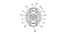
まず、本発明の一実施の形態におけるロックコネクタの構造について、図1〜図5を参照して説明する。図1は、本実施の形態における隔壁付き接続口部材との連通用ロックコネクタの側面図である。図2は、同ロックコネクタの断面図、図3は、同ロックコネクタの平面図である。図2は、図3におけるA−A断面を示したものである。図4は、同ロックコネクタの正面図、図5は、背面図である。 First, the structure of the lock connector according to one embodiment of the present invention will be described with reference to FIGS. FIG. 1 is a side view of a lock connector for communication with a connection port member with a partition wall in the present embodiment. FIG. 2 is a sectional view of the lock connector, and FIG. 3 is a plan view of the lock connector. FIG. 2 shows an AA cross section in FIG. 4 is a front view of the lock connector, and FIG. 5 is a rear view.
図1の側面図に示されるように、このロックコネクタは、中心に管体1を有する。図1には、管体1における基端部1aのみが示されているが、図2に示す断面図から判るように、管体1は更に先端部1bを有する。基端部1aには、使用に際して輸液管(図示せず)が接続される。先端部1bは、例えば医療用容器と輸液管とを連通させる際に、医療用容器などの接続口部材に設けられた隔壁(セプタム)のスリットを貫通して挿入される。 As shown in the side view of FIG. 1, the lock connector has a tube 1 at the center. FIG. 1 shows only the
管体1の先端部1bを包囲するように、略円筒状のフード2が配置されている。管体1の中央部には、一対の結合部3が設けられ、各々管体1の軸に直交する方向に延在している(図4参照)。フード2は、その基端側においての結合部3に接合され、管体1により支持されている。フード2は、図3に明瞭に示されるように、その円筒側壁に切り欠き部2aが形成されている。 A substantially
5はロックレバーである。ロックレバー5は、図2に明瞭に示されるように、管体1の側部に一対配置され、それぞれ管体1の軸方向に沿って延在する。管体1の中央部に設けられた一対の結合部3には、それぞれ円弧状の支持片4が結合している。支持片4の円弧形状は、結合部3から管体1に沿ってその周方向に延び、その先端は、ロックレバー5の軸方向中央部と結合している。したがって、ロックレバー5は、支持片4により管体1に対する所定位置に支持されている。図4、図5に示されるように、支持片4は、一つの結合部3から一対伸びている。したがって、1つのロックレバー5が一対の支持片4により支持されており、十分な強度が得られる。
ロックレバー5は、支持片4との結合部分から見た先端側が係止部5aを、基端側が操作部5bを構成している。ロックレバー5における係止部5aは、その先端に内方に突出する係止爪6を有する。係止部5aは、フード2の切り欠き部2a内に配置され、図3及び図4に示されるように、その外表面がフード2の外表面と略面一になっている。また、切り欠き部2aは先端側が閉じているので、ロックレバー5の係止部5aの先端は、平面的にはフード2により包囲され、使用時に接触を受けるおそれが軽減されている。 As for the
ロックレバー5における操作部5bは、その後端部に管体1に向かって延びた2片のストッパー片7a、7b(図5参照)を有する。一対の操作部5bに各々設けられたストッパー片7a(7b)は、管体1に向かって平行に延びている。 The
ロックレバー5における操作部5bに対して、管体1に接近する向きの押圧力、すなわち、図1あるいは図2に示される一対のロックレバー5の操作部5bを挟みこむように力を加えることにより、支持片4が可撓的に変形する。それにより、ロックレバー5は、支持片4との結合部近傍を中心として回動し、一対の係止爪6相互の間隔が拡大する。 By applying a pressing force in the direction approaching the tubular body 1 to the
上記のように、操作部5bが回動により管体1に接近したときに、ストッパー片7a、7bの先端が管体1に当接する。それにより、操作部5bと管体1の間の間隔が、所定の範囲よりも小さくならないように制限される。これは、操作部5bの回動による支持片4の変形を、塑性変形を生じない範囲に制限するためである。その際、各々2片のストッパー片7a、7bが設けられているため、管体1に対してその外周方向における2箇所で当接する。それにより、操作部5bの回動に対して、安定した制限作用を及ぼすことができる。 As described above, the tips of the
なお、操作部5bに対して、各々2片のストッパー片7a、7bを設けるのではなく、操作部5bに各々1片のストッパー片を設けた構造としてもよい。 In addition, it is good also as a structure which provided the
あるいは1つの操作部5bにおいて、2片のストッパー片7a(または7b)が管体1の両側に位置するように設けられてもよい。その場合は、操作部5bの回動に伴い、操作部5bに各々設けられたストッパー片の先端が、互いに他方の操作部に設けられたストッパー片の先端と当接することにより、操作部5bの回動が所定の範囲に制限される。 Alternatively, two
図1及び図3に示されるように、フード2の基端側には円筒面を一部窪ませた把持部2bが形成されている。この把持部2bは、コネクタの接続操作を行う際に、この部分を把持して操作することにより、操作の容易性を高めるためのものである。 As shown in FIGS. 1 and 3, a
以上の各要素は、一体化された一部材として構成されることが好ましい。材質としては、穿刺操作に必要な程度の硬度と、接続・離脱操作に必要な弾性(可撓性)を有することが要求される。例えば、ポリカーボネート、ポリプロピレン等が好適である。 Each of the above elements is preferably configured as an integrated member. The material is required to have a degree of hardness necessary for the puncture operation and elasticity (flexibility) necessary for the connection / disconnection operation. For example, polycarbonate, polypropylene and the like are suitable.
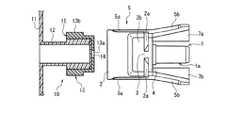
以上のように構成されたロックコネクタの動作について、図6〜図11を参照して説明する。各図には、上記コネクタが接続される対象である、医療用容器等の接続口部材10が示される。図6に、接続口部材10の正面図を示す。接続口部材10は、医療用容器等の容器本体11(一部のみを示す)に結合されており、容器本体11に固定された管状の喉部12と、喉部12の先端に取り付けられた円筒状の係合部13からなる。係合部13は、先端に連結孔13aを有し、後部が径大部13bとなっている。それにより、喉部12と係合部13の境界部に段差部15が形成されている。喉部12と係合部13は連通した内腔を有し、連結孔13aにより外部に対して開口している。連結孔13aは、セプタム14により封口されている。セプタム14は、喉部12の先端と、係合部13の内面により挟持されている。図7に示すように、セプタム14は中央部にスリットを有し、コネクタの管体1の先端部を挿入可能となっている。 The operation of the lock connector configured as described above will be described with reference to FIGS. Each drawing shows a
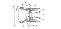
接続口部材10にコネクタを接続する際には、図6に示すように両者を対向させ、接続口部材10の係合部13がコネクタのフード2内に挿入されるように操作する。それにより、コネクタの管体1の先端部1bが接続口部材10の連結孔13aに対向し、セプタム14のスリットを割って、接続口部材10の内腔に挿入される。管体1を十分に挿入した状態が図8及び図9に示される。この状態においては、ロックレバー5の係止部5aに設けられた係止爪6が、接続口部材10の径大部13bを乗り越えて、係止爪6と径大部13b後端とが係合している。それにより、接続状態がロックされる。 When connecting the connector to the
接続を解除する際には、一対のロックレバー5における各操作部5bを指で把持し、挟みつける。それにより、図10及び図11に示されるように、支持片4が可撓的に変形し、ロックレバー5は、支持片4との結合部近傍を中心として回動する。その結果、一対の係止爪6の相互の間隔が離間して、接続口部材10の径大部13bとの係合が外れる。 When releasing the connection, each
また、操作部5bが回動により管体1に接近したときに、上述のとおり、ストッパー片7a、7bの先端が管体1に当接して、回動範囲が制限される。そのため、操作部5bの回動による支持片4の変形を、塑性変形を生じない範囲に制限することができる。 Moreover, when the
なお、支持片4は、結合部3から管体1に沿ってその周方向に延びる円弧状であるため、長さを十分にとることができる。その結果、操作部5bの回動に伴う変形に対して、十分な可撓性を持たせることが可能である。 In addition, since the
以上の構成および動作によれば、接続に際しては、接続口部材10とコネクタを相互に押し付ける操作を行うだけでよく、きわめて簡易である。 According to the above configuration and operation, when connecting, it is only necessary to perform an operation of pressing the
接続を解除する際には、操作部5bを指で挟みつけるだけでよい。ロックレバー5はフード2とは独立しており、支持片4にのみ支持されている。従って、係止部5aの先端の係止爪6を変位させるための、可撓的な変形の量を多くとることが容易である。その結果、径大部13bとの係合のための変形量を十分に確保して、確実な係合を得ることが可能である。 When releasing the connection, it is only necessary to pinch the
しかも、係止部5aはフード2に完全に包囲され、また、外表面がフード2の外表面と略面一であるため、係止部5aの先端が不慮の接触により変形させられる可能性が低くなる。従って、係合が外れる事故の発生が軽減される。 Moreover, since the locking
また、管体1の先端部1bがフード2内に収容された構造であるため、先端部1bを接触による汚染から保護することができ、輸液との接触部を清潔に保つことができる。 Further, since the
本発明の連通用ロックコネクタは、ロックを解除する際のロックレバーの回動操作による構成部材の復元不能な塑性変形を回避することが可能であり、輸液療法において使用される輸液バッグ等の医療用容器の接続口部材との連結に用いるコネクタとして有用である。 The communication lock connector of the present invention can avoid irreparable plastic deformation of components due to the turning operation of the lock lever when releasing the lock, and can be used for medical treatment such as infusion bags used in infusion therapy. It is useful as a connector used for connection with the connection port member of the container.
1、21 管体
1a、21a 基端部
1b、21b 先端部
2、22 フード
2a 切り欠き部
3 結合部
4、24 支持片
5、23 ロックレバー
5a、23a 係止部
5b、23b 操作部
6、25 係止爪
7a、7b ストッパー片
10 接続口部材
11 容器本体
12 喉部
13 係合部
13a 連結孔
13b 径大部
14 セプタム
15 段差部1, 21
Claims (8)
Translated fromJapanese前記管体の前記基端部と前記先端部の中間部分に固定され前記管体の横方向に延在する一対の結合部と、
前記管体の先端部を包囲するように配置され、前記結合部を介して前記管体と結合し、側壁に切り欠き部が形成されたフードと、
前記管体の側部に配置されて前記管体の軸方向に沿って延在し、先端側の係止部及び基端側の操作部を含む一対のロックレバーと、
前記一対のロックレバーにおける前記係止部と前記操作部の中間部をそれぞれ、前記一対の結合部と結合して前記ロックレバーを前記管体に対して支持する支持片とを備え、
前記ロックレバーの前記係止部は、その先端に内方に突出する係止爪を有するとともに、前記フードの前記切り欠き部内に、その外表面が前記フードの外表面と略面一になるように配置され、
前記ロックレバーの前記操作部が、その後端部に、前記管体に向かって突出するとともに前記管体の軸方向に沿って延在するストッパー片を有し、
前記操作部に対して前記管体に接近する向きの押圧力を加えることにより、前記支持片の可撓的な変形に伴い前記操作部が回動して、一対の前記係止爪相互の間隔が広がるように構成されるとともに、
前記操作部の前記回動に伴い、前記ストッパー片の先端が前記管体に当接することにより、前記操作部の回動が所定の範囲に制限される隔壁付き接続口部材との連通用ロックコネクタ。A tubular body having a proximal end portion connectable to the infusion tube and a distal end portion that can be inserted into the partition wall of the connection port member;
A pair of coupling portions fixed to an intermediate portion between the base end portion and the tip end portion of the tubular body and extending in a lateral direction of the tubular body;
A hood that is disposed so as to surround the tip of the tubular body, is coupled to the tubular body via the coupling portion, and has a notch formed in a side wall;
A pair of lock levers disposed on the side of the tube and extending along the axial direction of the tube, including a locking portion on the distal end side and an operation portion on the proximal end side;
A support piece for supporting the lock lever with respect to the tubular body by coupling the intermediate portion of the engagement portion and the operation portion of the pair of lock levers with the pair of coupling portions, respectively.
The locking portion of the lock lever has a locking claw protruding inward at the tip thereof, and the outer surface of the locking lever is substantially flush with the outer surface of the hood in the cutout portion of the hood. Placed in
The operation portion of the lock lever has a stopper piece that protrudes toward the tubular body and extends along the axial direction of the tubular body at a rear end portion thereof,
By applying a pressing force in the direction of approaching the tubular body to the operation portion, the operation portion rotates with the flexible deformation of the support piece, and the pair of locking claws are spaced apart from each other. Is configured to spread,
A lock connector for communication with a connection port member with a partition wall where the rotation of the operation portion is limited to a predetermined range by the tip of the stopper piece coming into contact with the tubular body with the rotation of the operation portion. .
前記管体の前記基端部と前記先端部の中間部分に固定され前記管体の横方向に延在する一対の結合部と、
前記管体の先端部を包囲するように配置され、前記結合部を介して前記管体と結合し、側壁に切り欠き部が形成されたフードと、
前記管体の側部に配置されて前記管体の軸方向に沿って延在し、先端側の係止部及び基端側の操作部を含む一対のロックレバーと、
前記一対のロックレバーにおける前記係止部と前記操作部の中間部をそれぞれ、前記一対の結合部と結合して前記ロックレバーを前記管体に対して支持する支持片とを備え、
前記ロックレバーの前記係止部は、その先端に内方に突出する係止爪を有するとともに、前記フードの前記切り欠き部内に、その外表面が前記フードの外表面と略面一になるように配置され、
前記ロックレバーの前記操作部が、その後端部に、前記管体に向かって突出するとともに前記管体の軸方向に沿って延在するストッパー片を有し、
前記操作部に対して前記管体に接近する向きの押圧力を加えることにより、前記支持片の可撓的な変形に伴い前記操作部が回動して、一対の前記係止爪相互の間隔が広がるように構成されるとともに、
前記操作部の前記回動に伴い、一対の前記操作部に設けられた前記ストッパー片の先端が、互いに他方の前記操作部に設けられた前記ストッパー片の先端と当接することにより、前記操作部の回動が所定の範囲に制限される隔壁付き接続口部材との連通用ロックコネクタ。A tubular body having a proximal end portion connectable to the infusion tube and a distal end portion that can be inserted into the partition wall of the connection port member;
A pair of coupling portions fixed to an intermediate portion between the base end portion and the tip end portion of the tubular body and extending in a lateral direction of the tubular body;
A hood that is disposed so as to surround the tip of the tubular body, is coupled to the tubular body via the coupling portion, and has a notch formed in a side wall;
A pair of lock levers disposed on the side of the tube and extending along the axial direction of the tube, including a locking portion on the distal end side and an operation portion on the proximal end side;
A support piece for supporting the lock lever with respect to the tubular body by coupling the intermediate portion of the engagement portion and the operation portion of the pair of lock levers with the pair of coupling portions, respectively.
The locking portion of the lock lever has a locking claw protruding inward at the tip thereof, and the outer surface of the locking lever is substantially flush with the outer surface of the hood in the cutout portion of the hood. Placed in
The operation portion of the lock lever has a stopper piece that protrudes toward the tubular body and extends along the axial direction of the tubular body at a rear end portion thereof,
By applying a pressing force in the direction of approaching the tubular body to the operation portion, the operation portion rotates with the flexible deformation of the support piece, and the pair of locking claws are spaced apart from each other. Is configured to spread,
Along with the rotation of the operation part, the tips of the stopper pieces provided in a pair of the operation parts come into contact with the tips of the stopper pieces provided in the other operation part. A lock connector for communication with a connection port member with a partition wall whose rotation is limited to a predetermined range.
前記接続口部材は、連通対象の本体に結合される管状の喉部と、前記喉部の先端に設けられ前記喉部との境界部に段差部を形成した径大部を有する略円筒状の係合部と、前記係合部の先端に設けられ前記係合部の内腔を外部に対して開口させた連結孔と、前記連結孔を封口する隔壁とを備え、
前記ロックコネクタのフード内に前記接続口部材の係合部を挿入することにより、前記管体の先端部が前記隔壁を貫通して前記接続口部材の内腔に挿入されるとともに、前記ロックレバーにおける係止爪が前記喉部との境界部の段差部に係合して、前記ロックコネクタと前記接続口部材の接続状態が保持されるコネクタ構造。A connector structure configured by a combination of the lock connector according to any one of claims 1 to 6 and a connection port member coupled to a communication target main body,
The connection port member has a substantially cylindrical shape having a tubular throat portion coupled to a communication target body and a large-diameter portion provided at a tip portion of the throat portion and forming a step portion at a boundary portion with the throat portion. An engagement portion; a connection hole provided at a distal end of the engagement portion and opening a lumen of the engagement portion to the outside; and a partition wall that seals the connection hole;
By inserting the engaging portion of the connection port member into the hood of the lock connector, the distal end portion of the tube passes through the partition wall and is inserted into the lumen of the connection port member, and the lock lever The connector structure in which the locking claw is engaged with the step portion at the boundary with the throat portion, and the connection state of the lock connector and the connection port member is maintained.
Priority Applications (1)
| Application Number | Priority Date | Filing Date | Title |
|---|---|---|---|
| JP2012100618AJP2012139554A (en) | 2012-04-26 | 2012-04-26 | Lock connector for communication |
Applications Claiming Priority (1)
| Application Number | Priority Date | Filing Date | Title |
|---|---|---|---|
| JP2012100618AJP2012139554A (en) | 2012-04-26 | 2012-04-26 | Lock connector for communication |
Related Parent Applications (1)
| Application Number | Title | Priority Date | Filing Date |
|---|---|---|---|
| JP2006172579ADivisionJP5067600B2 (en) | 2006-06-22 | 2006-06-22 | Lock connector for communication |
Publications (1)
| Publication Number | Publication Date |
|---|---|
| JP2012139554Atrue JP2012139554A (en) | 2012-07-26 |
Family
ID=46676411
Family Applications (1)
| Application Number | Title | Priority Date | Filing Date |
|---|---|---|---|
| JP2012100618APendingJP2012139554A (en) | 2012-04-26 | 2012-04-26 | Lock connector for communication |
Country Status (1)
| Country | Link |
|---|---|
| JP (1) | JP2012139554A (en) |
Citations (7)
| Publication number | Priority date | Publication date | Assignee | Title |
|---|---|---|---|---|
| US4500312A (en)* | 1982-12-15 | 1985-02-19 | Mcfarlane Richard H | Connecting assembly |
| US4573981A (en)* | 1983-10-24 | 1986-03-04 | Mcfarlane Richard H | Protective sheath structure for a catheter assembly |
| US4936837A (en)* | 1988-11-04 | 1990-06-26 | C. R. Bard, Inc. | Aseptic drainage outlet |
| JP2004000483A (en)* | 2002-02-25 | 2004-01-08 | Jms Co Ltd | Lock connector for communication with connection port member with partition wall |
| US20040232696A1 (en)* | 2001-09-04 | 2004-11-25 | Maxime Andre | Pre-assembled sealing connection |
| JP2006504911A (en)* | 2002-10-30 | 2006-02-09 | アー ライモント エ カンパニュイ | Connection element |
| JP2006141714A (en)* | 2004-11-19 | 2006-06-08 | Jms Co Ltd | Lock connector device for channel communication |
- 2012
- 2012-04-26JPJP2012100618Apatent/JP2012139554A/enactivePending
Patent Citations (7)
| Publication number | Priority date | Publication date | Assignee | Title |
|---|---|---|---|---|
| US4500312A (en)* | 1982-12-15 | 1985-02-19 | Mcfarlane Richard H | Connecting assembly |
| US4573981A (en)* | 1983-10-24 | 1986-03-04 | Mcfarlane Richard H | Protective sheath structure for a catheter assembly |
| US4936837A (en)* | 1988-11-04 | 1990-06-26 | C. R. Bard, Inc. | Aseptic drainage outlet |
| US20040232696A1 (en)* | 2001-09-04 | 2004-11-25 | Maxime Andre | Pre-assembled sealing connection |
| JP2004000483A (en)* | 2002-02-25 | 2004-01-08 | Jms Co Ltd | Lock connector for communication with connection port member with partition wall |
| JP2006504911A (en)* | 2002-10-30 | 2006-02-09 | アー ライモント エ カンパニュイ | Connection element |
| JP2006141714A (en)* | 2004-11-19 | 2006-06-08 | Jms Co Ltd | Lock connector device for channel communication |
Similar Documents
| Publication | Publication Date | Title |
|---|---|---|
| JP6094830B2 (en) | Male connector with locking mechanism | |
| JP7612779B2 (en) | System for sealed transfer of fluids and membrane construction for use therein - Patents.com | |
| JP4163975B2 (en) | Lock connector for communication with connection port member with bulkhead | |
| US11484471B2 (en) | Syringe adapter with disconnection feedback mechanism | |
| JP5994400B2 (en) | Female connector | |
| CN106470657B (en) | System for closed transfer of fluids | |
| JP6094829B2 (en) | Male connector with locking mechanism | |
| JP2006297062A (en) | Indwelling needle device | |
| JP6318531B2 (en) | Male connector, female connector, and connector set | |
| JP5067600B2 (en) | Lock connector for communication | |
| JP2018519107A (en) | Improved medical connector | |
| JP2012139554A (en) | Lock connector for communication | |
| JP4292145B2 (en) | Lock connector device for channel communication | |
| JP2017501751A (en) | Endoscope shaft joint | |
| JP2009112863A (en) | Lock connector device for channel communication | |
| JP5630288B2 (en) | Male member cover and male member with cover | |
| JP4568775B2 (en) | Connector structure with connection port member with bulkhead and communication lock connector | |
| JP2008132372A (en) | Lock connector for communication with connection port member with bulkhead | |
| JP2015144676A (en) | Syringe connecting body | |
| JP2012217639A (en) | Male member cover and male member with cover | |
| JP4683285B2 (en) | Indwelling needle device | |
| JP2011229646A (en) | Connection device of medical infusion tube having pulling-out function | |
| JP2003088568A (en) | Medical equipment |
Legal Events
| Date | Code | Title | Description |
|---|---|---|---|
| A621 | Written request for application examination | Free format text:JAPANESE INTERMEDIATE CODE: A621 Effective date:20120426 | |
| A131 | Notification of reasons for refusal | Free format text:JAPANESE INTERMEDIATE CODE: A131 Effective date:20130808 | |
| A521 | Written amendment | Free format text:JAPANESE INTERMEDIATE CODE: A523 Effective date:20131003 | |
| A02 | Decision of refusal | Free format text:JAPANESE INTERMEDIATE CODE: A02 Effective date:20131029 |