JP2012137428A - Piping monitoring system - Google Patents
Piping monitoring systemDownload PDFInfo
- Publication number
- JP2012137428A JP2012137428AJP2010291034AJP2010291034AJP2012137428AJP 2012137428 AJP2012137428 AJP 2012137428AJP 2010291034 AJP2010291034 AJP 2010291034AJP 2010291034 AJP2010291034 AJP 2010291034AJP 2012137428 AJP2012137428 AJP 2012137428A
- Authority
- JP
- Japan
- Prior art keywords
- electrode
- electret
- piping
- vibration
- group
- Prior art date
- Legal status (The legal status is an assumption and is not a legal conclusion. Google has not performed a legal analysis and makes no representation as to the accuracy of the status listed.)
- Withdrawn
Links
Images


Landscapes
- Testing Or Calibration Of Command Recording Devices (AREA)
- Arrangements For Transmission Of Measured Signals (AREA)
Abstract
Translated fromJapaneseDescription
Translated fromJapanese本発明は、配管モニタリングシステムに関する。 The present invention relates to a piping monitoring system.
住宅やビル、工場等で使用される水やガスの使用量は、料金計算の基準、需要予測の基礎データ、大量あるいは微量流量などの異常状態検知データ等として重要な情報である。現在、それらの使用量は、利用者世帯一戸毎に、水道管に設置された水道メータやガス管に設置されたガスメータを検針員が定期的に目視で検針することにより計測されているが、計測に人手や時間がかかる問題がある。
また、水道管やガス管は、破損、詰まり等の故障が生じると水漏れや断水、ガス漏れ等が生じて広範囲に影響が出るため、定期的な保守メンテナンスを行う必要がある。また、故障が生じた際にはその故障地点を早急に見つける必要がある。しかしこれらの配管は通常地下に配設されており、長さも長いことから、保守メンテナンスや故障地点の発見に人手や時間がかかってしまう。
そのため、上記のような水道管、ガス管等の配管の保守管理を省人力化できる技術が求められている。The amount of water and gas used in homes, buildings, factories, etc. is important information such as charge calculation standards, basic data for demand prediction, and abnormal state detection data such as large or minute flow rates. Currently, the amount of such usage is measured for each user household by regularly reading the water meter installed in the water pipe and the gas meter installed in the gas pipe visually. There is a problem that the measurement takes time and manpower.
In addition, water pipes and gas pipes are damaged or clogged, causing water leaks, water breaks, gas leaks, etc., which have a wide range of influences, so regular maintenance is required. In addition, when a failure occurs, it is necessary to quickly find the failure point. However, these pipes are usually arranged underground and are long, so it takes manpower and time to find maintenance and trouble spots.
Therefore, there is a need for a technique that can save labor in maintenance management of pipes such as water pipes and gas pipes as described above.
一方、従来、コンデンサマイクロフォンや静電誘導型振動発電器に、絶縁材料に電荷を注入したエレクトレット(Electret)を使用した静電誘導型変換素子が用いられている。エレクトレットを構成する絶縁材料としては、従来、主に、二酸化ケイ素等の無機材料が用いられている(たとえば特許文献1)。また、有機系の絶縁材料として、ポリカーボネート、ポリプロピレン、ポリテトラフルオロエチレン等の鎖状の高分子化合物も使用されている。
最近、エレクトレット材料として、主鎖に脂肪族環構造を有する含フッ素重合体を用いることが提案されている(特許文献2)。また、このような含フッ素重合体を用いたエレクトレットの表面電荷密度の向上のために、アミノ基を有するシランカップリング剤を配合することが提案されている(特許文献3)。On the other hand, electrostatic induction conversion elements using electrets in which electric charges are injected into an insulating material are conventionally used for condenser microphones and electrostatic induction vibration power generators. Conventionally, inorganic materials such as silicon dioxide have been mainly used as the insulating material constituting the electret (for example, Patent Document 1). In addition, chain polymer compounds such as polycarbonate, polypropylene, and polytetrafluoroethylene are also used as organic insulating materials.
Recently, it has been proposed to use a fluorine-containing polymer having an aliphatic ring structure in the main chain as an electret material (Patent Document 2). In addition, in order to improve the surface charge density of electrets using such a fluoropolymer, it has been proposed to blend a silane coupling agent having an amino group (Patent Document 3).
近年、複数のセンサノード(センサ付き無線端末)を分散配置したセンサネットワークシステムについての研究・開発が活発化している。センサネットワークシステムは、各センサノードが自立的に情報を取得して無線送信するため、配線が困難な場所に設置できる、人の手を介さずに多点の同時計測が可能である等の利点を有しており、多くの分野への応用が期待されている。センサノードは、通常、センサと、無線通信手段と、センサからの情報の処理および無線通信手段の動作の制御を行う制御手段と、それらの駆動に必要な電力を供給する電源とを備えている。
上述したセンサノードとして、配管内を流通する水やガスの流量等を計測できるものを使用し、これを配管に設置することにより配管モニタリングシステムを構築すれば、使用量(流量)の検針や配管の保守管理を省人力化できると考えられる。たとえば利用者世帯一戸毎にセンサノードを設置すれば、住居での使用される水やガスの使用量のデータが無線送信され、自動計測される。また、地下の配管に設置すれば、流量の変化等によって故障の発生箇所を特定でき、補修が容易となる。
しかし、上記配管モニタリングシステムを構築するに際しては、従来のセンサノードにおける電源の問題がある。センサノードの電源としては、従来、一次電池が用いられているが、この場合、定期的に電池の点検や交換を行う必要があり、省人力化のメリットが損なわれる。近年、低消費電力の無線通信技術の開発は進んでいるが、電池寿命には限界があり、たとえば8年以上の長期にわたる動作は難しい。また、交換による廃電池は確実に回収されないと環境上の問題にもなる。
電源として太陽電池を備えるセンサノードも提案されているが、水道管やガス管は通常屋外には露出していないため、太陽電池ではセンサの駆動や無線送信に必要な電力が得られず、配管モニタリングシステムを構築できない。
本発明は、上記事情に鑑みなされたものであり、配管の保守管理を省人力化できる配管モニタリングシステムを提供する。In recent years, research and development on sensor network systems in which a plurality of sensor nodes (wireless terminals with sensors) are arranged in a distributed manner has become active. The sensor network system can be installed in places where wiring is difficult because each sensor node independently acquires information and wirelessly transmits it, and it is possible to measure multiple points simultaneously without human intervention. It is expected to be applied in many fields. The sensor node normally includes a sensor, a wireless communication unit, a control unit that processes information from the sensor and controls the operation of the wireless communication unit, and a power source that supplies electric power necessary for driving the sensor node. .
If the sensor node mentioned above can be used to measure the flow rate of water or gas flowing through the pipe, and if this is installed in the pipe, a pipe monitoring system will be constructed, the metering and pipe for the amount used (flow) It is thought that the maintenance management can be labor-saving. For example, if a sensor node is installed for each user household, data on the amount of water and gas used in the residence is wirelessly transmitted and automatically measured. Also, if installed in underground piping, the location of failure can be identified by the change in flow rate, etc., and repair becomes easy.
However, when constructing the piping monitoring system, there is a problem of power supply in the conventional sensor node. Conventionally, a primary battery is used as the power source of the sensor node. In this case, however, it is necessary to periodically inspect and replace the battery, and the merit of saving labor is lost. In recent years, the development of low-power-consumption wireless communication technology has progressed, but the battery life is limited, and for example, it is difficult to operate for a long period of 8 years or longer. Further, if the waste batteries after replacement are not reliably collected, there is an environmental problem.
Sensor nodes equipped with solar cells as power sources have also been proposed, but water pipes and gas pipes are usually not exposed outdoors, so solar cells cannot provide power necessary for sensor drive and wireless transmission, and piping A monitoring system cannot be constructed.
The present invention has been made in view of the above circumstances, and provides a pipe monitoring system capable of saving labor in pipe maintenance.
本発明は、以下の[1]〜[7]である。
[1]配管に設置され、配管内を流通する流体の状況を示す情報を検知してその情報を無線送信する複数のセンサノードと、前記センサノードから無線送信された情報を受信する受信装置とを備える配管モニタリングシステムであって、
前記センサノードが、独立した電源として振動発電器を備え、
前記振動発電器が、第一の電極と、前記第一の電極上に設けられたエレクトレットと、前記エレクトレットから離間配置された第二の電極とを備え、配管の振動によって前記エレクトレットおよび前記第二の電極の一方が他方に対して相対的に運動するように構成された静電誘導型発電素子を備え、
前記エレクトレットが、主鎖に脂肪族環を有する含フッ素重合体(a)または該含フッ素重合体(a)に由来する材料(a’)を含有する樹脂膜に電荷を注入してなるものであることを特徴とする配管モニタリングシステム。
[2]前記エレクトレットおよび前記第二の電極の一方が、他方に対して平行に配置され、前記配管の中心方向に向かって垂直方向に往復運動するように構成されている、[1]に記載の配管モニタリングシステム。
[3]前記静電誘導型発電素子が、前記配管の外周上に複数設置されている、[1]または[2]に記載の配管モニタリングシステム。
[4]前記配管内を流通する流体の状況を示す情報が、温度、圧力および流量から選ばれる少なくとも1種である、[1]〜[3]のいずれか一項に記載の配管モニタリングシステム。
[5]前記配管が水道管またはガス管である、[1]〜[4]のいずれか一項に記載の配管モニタリングシステム。
[6]前記含フッ素重合体(a)が、末端基としてカルボキシ基またはアルコキシカルボニル基を有する、[1]〜[5]のいずれか一項に記載の配管モニタリングシステム。
[7]前記材料(a’)が、前記含フッ素重合体(a)と、アミノ基を有するシランカップリング剤との混合物または反応生成物を含む、[1]〜[6]のいずれか一項に記載の配管モニタリングシステム。The present invention includes the following [1] to [7].
[1] A plurality of sensor nodes that are installed in a pipe and detect information indicating a state of fluid flowing in the pipe and wirelessly transmit the information; and a receiver that receives information wirelessly transmitted from the sensor node; A piping monitoring system comprising:
The sensor node includes a vibration power generator as an independent power source,
The vibration power generator includes a first electrode, an electret provided on the first electrode, and a second electrode spaced apart from the electret, and the electret and the second by vibration of piping. An electrostatic induction power generating element configured so that one of the electrodes moves relative to the other,
The electret is formed by injecting electric charge into a fluoropolymer (a) having an aliphatic ring in the main chain or a resin film containing a material (a ′) derived from the fluoropolymer (a). A piping monitoring system characterized by being.
[2] One of the electret and the second electrode is arranged in parallel to the other, and is configured to reciprocate in a vertical direction toward the central direction of the pipe. Piping monitoring system.
[3] The pipe monitoring system according to [1] or [2], wherein a plurality of the electrostatic induction power generation elements are installed on an outer periphery of the pipe.
[4] The pipe monitoring system according to any one of [1] to [3], wherein the information indicating the state of the fluid flowing through the pipe is at least one selected from temperature, pressure, and flow rate.
[5] The pipe monitoring system according to any one of [1] to [4], wherein the pipe is a water pipe or a gas pipe.
[6] The piping monitoring system according to any one of [1] to [5], wherein the fluoropolymer (a) has a carboxy group or an alkoxycarbonyl group as a terminal group.
[7] Any one of [1] to [6], wherein the material (a ′) includes a mixture or a reaction product of the fluoropolymer (a) and a silane coupling agent having an amino group. The piping monitoring system according to item.
本発明によれば、配管の保守管理を省人力化できる配管モニタリングシステムを提供できる。 According to the present invention, it is possible to provide a pipe monitoring system capable of saving labor in pipe maintenance.
本発明の配管モニタリングシステムは、配管に設置され、配管内を流通する流体の状況を示す情報を検知してその情報を無線送信する複数のセンサノードと、前記センサノードから無線送信された情報を受信する受信装置とを備える配管モニタリングシステムであって、前記センサノードが、電源として振動発電器を備え、前記振動発電器が、第一の電極と、前記第一の電極上に設けられたエレクトレットと、前記エレクトレットから離間配置された第二の電極とを備え、配管の振動によって前記エレクトレットおよび前記第二の電極の一方が他方に対して相対的に運動するように構成された静電誘導型発電素子を備え、前記エレクトレットが、主鎖に脂肪族環を有する含フッ素重合体(a)または該含フッ素重合体(a)に由来する材料(a’)を含有する樹脂膜に電荷を注入してなるものであることを特徴とする。
本発明において、「流体」としては、特に限定されず、たとえば都市ガス、プロパンガス等の気体;水、アルコール、エーテル等の液体;炭酸水等の気体と液体との混合物;下水等の液体と固体との混合物;等が挙げられる。
配管は、その内部を流体が流通するものであれば特に限定されず、たとえばガス管、水道管(上水道管)、下水道管、プラント配管(石油コンビナートにおける石油配管、ビール工場におけるビール流通配管、化学工場における原料や生成物の流通配管等)、輸送配管(油田から石油コンビナートまでの石油の輸送配管、石油コンビナート間の石油の輸送配管等)等が挙げられる。これらの中でも、ガス管または水道管が好適である。現在、水やガスの使用量は、主に、利用者世帯一戸毎に設置された水道メータやガスメータを検針員が毎月目視で検針することにより管理されており、この管理に人手や時間がかかっている。そのため、検針の自動化の要求が大きく、本発明の有効性が大きい。
センサノードにより検知する、配管内を流通する流体の状況を示す情報としては、たとえば、温度、圧力、流量、振動、音響、pH、ウォーターハンマ等が挙げられる。これらの中でも、流体の状態を把握できる点で、温度、圧力および流量から選ばれる少なくとも1種が好ましい。A pipe monitoring system according to the present invention includes a plurality of sensor nodes which are installed in a pipe and detect information indicating a state of a fluid flowing in the pipe and wirelessly transmit the information, and information wirelessly transmitted from the sensor node. A pipe monitoring system including a receiving device for receiving, wherein the sensor node includes a vibration power generator as a power source, and the vibration power generator includes a first electrode and an electret provided on the first electrode. And a second electrode spaced from the electret, and one of the electret and the second electrode is moved relative to the other by vibration of piping. A fluorinated polymer (a) having a power generation element and the electret having an aliphatic ring in the main chain or a material derived from the fluorinated polymer (a) ( Characterized in that the resin film containing the ') is made by injecting the charge.
In the present invention, the “fluid” is not particularly limited. For example, a gas such as city gas or propane gas; a liquid such as water, alcohol or ether; a mixture of a gas and liquid such as carbonated water; a liquid such as sewage A mixture with a solid; and the like.
Piping is not particularly limited as long as fluid flows through the inside thereof. For example, gas pipes, water pipes (water pipes), sewer pipes, plant pipes (oil pipes in petroleum complexes, beer circulation pipes in beer factories, chemicals) Raw material and product distribution pipes in factories), transport pipes (oil transport pipes from oil fields to oil complexes, oil transport pipes between oil complexes, etc.) and the like. Among these, a gas pipe or a water pipe is preferable. Currently, the amount of water and gas used is mainly managed by monthly meter readings of water meters and gas meters installed in each user household, and this management takes time and labor. ing. Therefore, there is a great demand for automation of meter reading, and the effectiveness of the present invention is great.
Examples of information indicating the state of the fluid flowing through the pipe detected by the sensor node include temperature, pressure, flow rate, vibration, sound, pH, and water hammer. Among these, at least one selected from temperature, pressure, and flow rate is preferable in that the state of the fluid can be grasped.
本発明によれば、配管の保守管理を省人力化できる。
すなわち、配管は、内部に流体が流通している状態では必ず振動している。また、流体の流通が停止している状態でも、配管が設置されている環境下に存在する振動(車両等の移動体の移動による振動等)や、配管内に流体を流通させるために設置されているモータ、コンプレッサ等の振動によってある程度振動している。また減圧弁、レギュレータ、ガバナ等では圧力を調整する際、すなわち弁の動作時には大きな振動が発生する。前記静電誘導型発電素子を備える振動発電器は、エレクトレットに特定の材料が用いられていることにより、低周波数の振動での発電効率が高い。そのため、該静電誘導型発電素子を電源として用いることにより、配管の振動によって、センサノードの駆動に充分な電力が得られる。そのため、このセンサノードは、電源として太陽電池を採用する場合のように設置場所が限定されることがなく、たとえば従来水道メータやガスメータが設置されている場所や地下のような光源のない場所に配設された配管にも適用できる。
また、振動発電器としては、エレクトレットを用いた静電誘導型のもののほか、電磁誘導型のものや圧電型のものが知られているが、前者はコイルが必須であるために発電器自身が重くなり設置上の制約があり、後者は振動子のスペースを確保する必要があり、かつ材料耐久性が低く発電器の寿命に問題があった。さらに、これらは低周波数の振動での発電効率が静電誘導型のものに比べて容積に比較して低く、配管の振動が微細である場合には充分な電力が得られない。そのため、センサノードの駆動に必要な電力を得るためには、低周波数の振動を増幅して発電器に伝達する増幅機構を設けたり、発電器を大型化する必要があり、重量、コスト等が増大する。また、圧電型の場合、圧電素子を取り付けた振動板が変形することによって発電が行われるため、部品の劣化が生じやすい。これに対し、静電誘導型、特に上記特定材料で構成したエレクトレットを備えるものを用いる場合は、増幅機構がなくても低周波数の振動で充分な発電量が得られるため、他の振動発電器を採用する場合に比べて、軽量化や小型化(薄型化)が可能で、コストも低い。また、前記静電誘導型発電素子は、エレクトレット自体の寿命が長い(電荷保持安定性が高い)こと、エレクトレットを変形させたり他の部材と接触させる必要がないことなどから、全体としての耐久性も優れている。
そのため、本発明によれば、配管内を流通する流体の状況(たとえば流量、圧力、温度等)のモニタリングを、センサノードの保守メンテナンスを行わなくても、長期(たとえば8年以上)にわたって実施できる。また、現在、水やガスの使用量の管理に利用されている水道メータやガスメータの代わりにセンサノードを設置し、水やガスの使用量が無線送信されるようにすることで、その管理に要する人手や時間を軽減できる。According to the present invention, maintenance management of piping can be labor-saving.
In other words, the pipe always vibrates in a state where the fluid is circulating inside. Even when the flow of fluid is stopped, it is installed to circulate the fluid in the environment where the pipe is installed (vibration caused by the movement of a moving body such as a vehicle) and the fluid in the pipe. It is vibrating to some extent due to the vibration of the motor and compressor. Further, in a pressure reducing valve, a regulator, a governor or the like, a large vibration is generated when the pressure is adjusted, that is, during the operation of the valve. The vibration power generator including the electrostatic induction power generation element has high power generation efficiency at low-frequency vibration because a specific material is used for the electret. Therefore, by using the electrostatic induction power generating element as a power source, sufficient electric power for driving the sensor node can be obtained by vibration of the piping. Therefore, the installation location of this sensor node is not limited as in the case where a solar cell is adopted as the power source. For example, the sensor node is installed in a place where a conventional water meter or gas meter is installed or in a place where there is no light source such as underground. It can also be applied to installed pipes.
In addition to the electrostatic induction type using an electret, an electromagnetic induction type and a piezoelectric type are known as vibration power generators. However, since the former requires a coil, The latter is heavy and there are restrictions on installation, and the latter needs to secure a space for the vibrator, and the durability of the material is low and there is a problem in the life of the generator. Furthermore, these have low power generation efficiency at low frequency vibration compared to the electrostatic induction type, and sufficient power cannot be obtained when the vibration of the pipe is fine. Therefore, in order to obtain electric power necessary for driving the sensor node, it is necessary to provide an amplification mechanism that amplifies low-frequency vibrations and transmits the vibration to the generator, or to increase the size of the generator. Increase. Further, in the case of the piezoelectric type, power generation is performed by deforming the diaphragm to which the piezoelectric element is attached, so that the components are likely to deteriorate. On the other hand, when using an electrostatic induction type, particularly one equipped with an electret composed of the above specific material, a sufficient amount of power can be obtained with low-frequency vibration even without an amplification mechanism. Compared to the case of adopting, it is possible to reduce the weight and size (thinner), and lower the cost. In addition, the electrostatic induction power generating element has a long life span (high charge retention stability), and it is not necessary to deform the electret or to contact other members. Is also excellent.
Therefore, according to the present invention, monitoring of the state of fluid flowing in the pipe (for example, flow rate, pressure, temperature, etc.) can be performed over a long period (for example, 8 years or more) without maintenance of the sensor node. . In addition, a sensor node is installed instead of a water meter or gas meter that is currently used to manage water and gas usage, so that water and gas usage can be transmitted wirelessly. The labor and time required can be reduced.
本発明の配管モニタリングシステムの一実施形態を、図面を用いて説明する。
図1に、本実施形態の配管モニタリングシステムの概略構成を説明する概念図を示す。
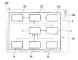
本実施形態の配管モニタリングシステムは、水道管200内を流通する水の状況を示す情報を検知してその情報を無線送信する複数のセンサノード100と、無線送信された情報を受信して無線送信する複数の中継ノード(受信装置)110と、中継ノード110から有線または無線で送信された情報を受信するゲートウェイ(受信装置)120とから構成される無線ネットワークを備える。
水道管200は、地下に配設された主管201と、主管201から分岐して、図示しない複数の住宅それぞれに対して水を供給する分配管202とから構成されており、分配管202は住宅内の水道設備に接続されている。複数のセンサノード100はそれぞれ分配管202に取り付けられている。
ゲートウェイ120は、図示しない有線または無線の通信回線(インターネット等)を介して図示しないサーバに接続されている。An embodiment of a piping monitoring system of the present invention will be described with reference to the drawings.
In FIG. 1, the conceptual diagram explaining schematic structure of the piping monitoring system of this embodiment is shown.
The piping monitoring system according to the present embodiment detects information indicating the state of water flowing in the
The
The
本実施形態では、上記無線ネットワークおよびサーバにより、水道管200内を流通する水の状況の監視が行われる。
まず、センサノード100が、当該センサノード100が設置された場所の分配管202内を流通する水の状況を示す情報(以下、単にデータということがある。)を検知し、無線送信する。センサノード100から無線送信されたデータは、中継ノード110を介してゲートウェイ120に無線送信される。ゲートウェイ120で受信されたデータは、有線または無線の通信回線を介してサーバに送られる。
サーバは、送られたデータの処理(記録、解析等)を行い、必要に応じて、サーバに接続された周辺機器(警報装置等)を作動させる。たとえばセンサノード100から送られたデータを、当該データを発信したセンサノード100の設置位置または該センサノード100が備えるセンサの識別番号と対応させて記録する。また、データを解析し、該データが異常値であると判定した場合(たとえば分配管202内を流通する水の流量や圧力が予め設定された値(閾値)を下回った場合、直前のデータからの変動幅が設定値を超えた場合等)、警報装置を作動させ、表示(文字、画像、発光等)や音(アラーム、音声等)により警報を告知させる。また、水道管200に漏水が生じた場合、漏水箇所またはその近傍に設置されたセンサノード100から送られるデータは大きく変動するため、複数のセンサノード100からのデータを解析することで、水道管200の漏水箇所を早期発見できる。
本実施形態において、センサノード100以外の構成は特に限定されず、従来、センサネットワークシステムを構成する中継ノード、ゲートウェイ、サーバ等として提案されているものが利用できる。In the present embodiment, the state of water flowing through the
First, the
The server performs processing (recording, analysis, etc.) of the sent data, and activates peripheral devices (alarm devices, etc.) connected to the server as necessary. For example, the data sent from the
In the present embodiment, the configuration other than the
≪センサノード100≫
図2に、センサノード100の概略構成を説明するブロック図を示す。
センサノード100は、電源部101と、センサ102と、通信部103と、アンテナ104と、センサ102からの出力信号の処理および通信部103の制御を行う制御部105とを備える。
センサノード100においては、電源部101から制御部105に対し、各部の駆動に必要な電力が供給されるようになっている。すなわち、制御部105の駆動に必要な電力は電源部101から直接供給され、通信部103の駆動に必要な電力は制御部105を介して供給されるようになっている。センサ102がその駆動に電力を要するものである場合はその電力も制御部105を介して供給される。<<
FIG. 2 is a block diagram illustrating a schematic configuration of the
The
In the
電源部101は、3つの振動発電器1a、1b、1c(以下、これらをまとめて振動発電器1ということがある。)と、電力制御回路2と、振動発電器1で発電された電力を充電するための蓄電部5とを備える。
3つの振動発電器1を備えることで、電源部101を、1つで3軸全ての振動を認識できるように構成することができる。つまり、後述するようにエレクトレットの振動方向と分配管202の振動方向が一致すると、発電効率が向上する。1つの振動発電器1が1つのエレクトレットを備える場合、3つの振動発電器1を、それぞれのエレクトレットの振動方向が互いに直交する3方向(X軸、Y軸、Z軸)と一致するように配置することで、分配管202の振動方向が変化した場合でも、電源部101が3軸全ての振動を認識し、効率よく発電が行われる。
なお、ここでは3つの振動発電器1を備える例を示したが本発明はこれに限定されるものではない。電源部101が備える振動発電器1の数は必ずしも3つである必要はなく、1個以上であればよい。上限は特に限定されないが、分配管202のX、Y、Zの3軸の振動を確実に認識するためには、12個以下が好ましく、6個以下がより好ましい。コストの点から3つが特に好ましい。
振動発電器1が複数の場合、全てを使用する必要はなく、いずれか1つ以上を使用すればよい。The
By providing the three
In addition, although the example provided with the three
When there are a plurality of
図3に、振動発電器1の概略構成を説明するブロック図を示す。
振動発電器1は、静電誘導型発電素子3と電力変換回路部4とを備える。
詳細は後で図5〜6を用いて説明するが、静電誘導型発電素子3は、エレクトレット12が設けられた第一の電極11と、該エレクトレット12から離間配置された第二の電極21とを備え、分配管202の振動によってエレクトレット12が第二の電極21に対して相対的に運動するように構成されているものである。この相対的な運動によって交流電力が発電される。
電力変換回路部4は、整流回路41と、電圧変換回路42とを備える。整流回路41は、静電誘導型発電素子3で発電された交流電力を整流して直流電力に変換する回路である。電圧変換回路42は、整流回路41で整流された直流電流の電圧値を使用される二次電池の充電に最適な電圧に変換する回路であり、整流回路41から入力された直流電流の電圧値が、振動発電器1からの出力電圧値に変換される。FIG. 3 is a block diagram illustrating a schematic configuration of the
The
Although details will be described later with reference to FIGS. 5 to 6, the electrostatic induction
The power conversion circuit unit 4 includes a
電力制御回路2は、1つ以上の振動発電器1から出力される直流電圧値に応じて、高効率かつ安全に蓄電部5に電力供給するために、それら直流電力をミキシングして、蓄電部5に電力供給する回路である。たとえば振動発電器1が3つ備わっている場合、設置された環境条件によっては、静電誘導型発電素子3の交流発電量が大きく異なり、各振動発電器1の内部に備わっている電圧変換回路42では調整しきれず、各振動発電器1からの出力電圧に大きな差が生じる。各振動発電器1から出力される電圧を、電力制御回路2内部に構成される電圧検出回路でモニターして、高効率かつ安全な出力回路構成に切り替える。 The
蓄電部5は、図示しない二次電池および充放電制御回路を備える。
充放電制御回路は、振動発電器1から出力された直流電力を二次電池に充電あるいは二次電池から放電する時に、二次電池を保護するための過充電、過放電を防止するための制御回路と、効率良く充電、放電するための制御回路とを備える。The
The charge / discharge control circuit is a control for preventing overcharge and overdischarge for protecting the secondary battery when the DC power output from the
センサ102は、分配管202内を流通する水の状況を示す情報を検知し、その情報を、制御部105で処理可能な信号(振動による発電出力そのまま、あるいは0/1等)に変換して出力するものである。
センサ102により検知する、分配管202内を流通する水の状況を示す情報としては、センサノードにより検知する、配管内を流通する流体の状況を示す情報として前述したものと同様のものが挙げられ、特に、温度、圧力および流量から選ばれる少なくとも1種が好ましい。
センサ102の種類は、検知しようとする情報に応じて公知のものが利用できる。センサ102は、分配管202内を流通する水の状況を示す情報を、当該センサ102が分配管202内の水と接触して直接検知するものであってもよく、分配管202外部から間接的に検知するものであってもよい。たとえばセンサ102が振動センサであると、分配管202の振動を検知できる。この場合、振動の大きさや変化によって、分配管202内における水の流通の有無、流量、流量の変化等を検知できる。
1つのセンサノード100が備えるセンサ102の数は1個でも2個以上でもよい。また、複数個のセンサ102を備える場合、各センサ102の種類は同じであっても異なってもよい。複数種のセンサを組み合わせることで、1つのセンサノード100で複数の情報を検知するように構成できる。The
The information indicating the state of water flowing through the
As the type of the
The number of
通信部103およびアンテナ104はそれぞれ限定されず、従来、無線通信に用いられている送信機およびアンテナが利用できる。
制御部105は、センサ102からの出力信号に基づく情報がそのまま送信機104から無線送信されるように構成されてもよく、センサ102からの出力信号に基づき分配管202内を流通する流体の状況の異常(たとえば漏水、ガス漏れ等)の有無を判定する判定手段を設け、その判定結果が送信機104から無線送信されるように構成されてもよい。
前記異常の有無を判定する判定手段としては、たとえば、コンパレータ、ダイオード等が挙げられる。たとえばコンパレータを用いると、入力された信号(電圧値または電流値)が予め設定された閾値以下である場合と閾値超である場合とで、異なる信号が出力されるように構成できる。ダイオードを用いると、閾値超である場合のみ信号が出力されるように構成できる。また常時センシングを行う場合でも、数秒から数分に1回の割合でセンシングすれば充分な時には、センサ102と、センサ102からの出力信号を処理する制御部105内の回路をタイマーによって間歇動作させることにより、低消費電力化が図られ、電源部のさらなる小型化を図ることが可能となる。The
The
Examples of the determination means for determining the presence or absence of abnormality include a comparator and a diode. For example, when a comparator is used, different signals can be output depending on whether the input signal (voltage value or current value) is less than or equal to a preset threshold value and when it is greater than the threshold value. When a diode is used, a signal can be output only when the threshold is exceeded. In addition, even when performing continuous sensing, when it is sufficient to sense at a rate of once every few seconds to several minutes, the
センサ102として静電誘導型の振動センサを採用し、前記判定手段としてコンパレータを採用した場合を例に挙げて上記の判定動作を説明する。
静電誘導型の振動センサは、振動エネルギーを電気エネルギーに変換するセンサであり、生じた電気エネルギーの大きさが振動の大きさに比例することを利用して振動の大きさが求められる。電気エネルギーの大きさは電圧値として表される。
振動センサからコンパレータに電圧値が入力されると、コンパレータは、振動センサから入力された電圧値と、予め設定されている設定電圧値(閾値)とを比較し、その比較結果において、入力された電圧値が設定電圧値以下である場合(振動の大きさが正常範囲内である場合)、入力された電圧値が設定電圧値を超える場合(振動の大きさが異常である場合)それぞれに応じた信号を出力する。The determination operation will be described by taking as an example a case where an electrostatic induction type vibration sensor is employed as the
The electrostatic induction type vibration sensor is a sensor that converts vibration energy into electric energy, and the magnitude of vibration is obtained by utilizing the fact that the magnitude of the generated electric energy is proportional to the magnitude of vibration. The magnitude of electrical energy is expressed as a voltage value.
When a voltage value is input from the vibration sensor to the comparator, the comparator compares the voltage value input from the vibration sensor with a preset voltage value (threshold), and the comparison result indicates that the voltage value is input. Depending on whether the voltage value is less than or equal to the set voltage value (when the magnitude of vibration is within the normal range), or when the input voltage value exceeds the set voltage value (when the magnitude of vibration is abnormal) Output the signal.
センサノード100において、振動発電器1、センサ102、通信部103、制御部105、電力制御回路2および蓄電部5は筐体6内に収納されている。
センサノード100は、この筐体6を分配管202に取り付け、振動発電器1を分配管202の外周上に配置することにより分配管202に設置される。なお、振動発電器1は設置の都合上、筐体6内に収納しなくてもよい。また、図2には、センサノード100が、振動発電器1、センサ102、通信部103、制御部105、電力制御回路2および蓄電部5を収納した筐体6を1個備える例を示したが、該筐体6を複数備えてもよい。
振動発電器1は、後述する図5に示すように、薄型平型の構造であるため、配管・レギュレータおよびガバナ、あるいはメータ類の表面に水平または垂直に一個ないしは複数個設置される。In the
The
As shown in FIG. 5 to be described later, the
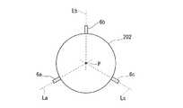
図4に、センサノード100として、振動発電器1、センサ102、通信部103、制御部105、電力制御回路2および蓄電部5を収納した筐体6を3個備えるものを用い、該3個の筐体6a、6b、6cを分配管202に設置した状態を示す概略側面図を示す。図4に示す態様において、筐体6a、6b、6cはそれぞれ、振動発電器1を1つずつ収納している。
筐体6a、6b、6cは、それぞれに収納された振動発電器1が備えるエレクトレット12の振動方向(後述する図5〜6中の矢印D方向)が、筐体6a、6b、6cの設置位置と分配管202の中心Pとを結ぶ直線La、Lb、Lcに一致するように設置されている。これにより、エレクトレット12が、分配管202の中心P方向に向かって垂直方向に(分配管202の長手方向に対して垂直に)往復運動(振動)するようになっている。エレクトレット12が上記のように振動するように配置されていると、エレクトレット12の振動方向と分配管202の振動方向とが一致しやすい。これらの振動方向が一致すると、分配管202の振動エネルギーが効率よく振動発電器1に伝達され、発電効率が向上する。
また、各筐体6a、6b、6cは、分配管202の長手方向に対して垂直な断面の円周上に等間隔に設置されている。分配管202の振動方向は通常、一定ではない。上記のように複数の筐体6a、6b、6cをそれぞれ分配管202の中心Pから見て異なる方向に設置することで、分配管202の振動方向が変化しても6a〜6cのうちのいずれかの筐体に収納された振動発電器1で効率よく発電が行われる。そのため、制御部105に電力を安定供給できる。In FIG. 4, the
The
The
筐体6の外形寸法は、特に限定されず、収納する振動発電器1、センサ102等の大きさや数、取り付ける分配管202の大きさ等に応じて適宜設定できる。
なお、図4には筐体6として3個の筐体6a、6b、6cを前述のように設置した例を示したが、本発明はこれに限定されるものではない。
たとえば筐体6の数は1個以上であればよい。上限は特に限定されないが、コスト等を考慮すると、12個以下が好ましく、6個以下がより好ましく、3個以下が特に好ましい。
また、複数の筐体6を設置するのは、分配管202の長手方向に対して垂直な断面の円周上でなくてもよい。たとえば分配管202の外周面上に螺旋状に配置してもよい。ただしこの場合においても、各振動発電器1はそれぞれ分配管202の中心Pから見て異なる方向に設置されることが好ましい。The external dimensions of the
Although FIG. 4 shows an example in which three
For example, the number of
The plurality of
振動発電器1の概略構造を、図5〜6に示す。図5は、振動発電器1の斜視分解図であり、図6は振動発電器1の部分断面図である。
本実施形態において、振動発電器1は、第一の電極11およびエレクトレット12を備える上部ユニットAと、第二の電極21を備える下部ユニットBとから構成される。
上部ユニットAは、第一の電極11、エレクトレット12および表面が平滑な長方形状の第一の基板13から構成される可動電極部10と、矩形の枠部材14と、第一の基板13を枠部材14に取り付けるばね部材15a、15bとから構成される。
上部ユニットAにおいて、可動電極部10は、枠部材14の枠内に配置され、第一の基板13の長辺側の両側縁がそれぞればね部材15a、15bによって枠部材14に取り付けられている。これにより、可動電極部10が、枠部材14の枠内で一定方向(図5〜6中の矢印D方向)に往復運動(振動)できるようになっている。
下部ユニットBは、第二の電極21および表面が平滑な長方形状の第二の基板22から構成される固定電極部20と、電力変換回路部4と、固定部材23とから構成される。
本実施形態においては、可動電極部10および固定電極部20により静電誘導型発電素子3が構成されている。
静電誘導型発電素子3の第一の電極11および第二の電極21はそれぞれ電力変換回路部4の整流回路41に接続されている。
なお、上部ユニットAと下部ユニットBとが入れ替わってもよい。A schematic structure of the
In the present embodiment, the
The upper unit A includes a
In the upper unit A, the
The lower unit B includes a fixed
In the present embodiment, the electrostatic induction
The
The upper unit A and the lower unit B may be interchanged.
<上部ユニットA>
図7に、可動電極部10の、第一の電極11およびエレクトレット12が設けられている側の平面図を示す。
図7に示すように、第一の電極11は、櫛形状のパターンで形成されたパターン電極であり、複数のライン状の櫛歯部分11aと、各櫛歯部分11aの一端を連絡する直線部11bとから構成される。
櫛歯部分11aは、ラインの長手方向が、可動電極部10の振動方向Dに交差するように形成されている。
直線部11bの末端は、図示しない配線によって電力変換回路部4の整流回路41に接続されている。<Upper unit A>
In FIG. 7, the top view of the side by which the
As shown in FIG. 7, the
The
The end of the
櫛歯部分11aの幅(振動方向Dにおける長さ)は、特に限定されないが、該幅が小さいほど、小さな相対運動(振動)によって運動エネルギーから電気エネルギーへの変換を行うことができ、変換効率が向上するため好ましい。そのため、櫛歯部分11aの幅は、それぞれ、1,000μm以下が好ましく、500μm以下がより好ましく、300μm以下が特に好ましい。該幅の下限は特に限定されないが、耐久性、生産性、エレクトレットとしての特性(表面電荷密度の高さやその安定性、静電反発特性、寄生静電容量等)等を考慮すると、50μm以上が好ましく、100μm以上が特に好ましい。
第一の電極11は、単一の層からなるものであってもよく、複数の層からなるものであってもよく、組成に分布のある構造を形成していてもよい。
第一の電極11の厚さ(複数の層よりなる場合は合計の厚さ)は、それぞれ、10〜1,000nmが好ましく、100〜500nmが特に好ましい。該厚さが上記範囲内であると、導電性、生産性に優れる。
第一の電極11の厚さは、触針式表面形状測定器(ULVAC社製DEKTAK8等)により測定できる。The width (length in the vibration direction D) of the comb-
The
The thickness of the first electrode 11 (in the case of a plurality of layers, the total thickness) is preferably 10 to 1,000 nm, particularly preferably 100 to 500 nm. When the thickness is within the above range, the conductivity and productivity are excellent.
The thickness of the
第一の電極11を構成する材料としては、導電性を有するものであれば特に限定されない。該材料の抵抗値としては体積固有抵抗値で0.1Ωcm以下が好ましく、0.01Ωcm以下が特に好ましい。
導電性材料として具体的には、金、銀、銅、ニッケル、クロム、アルミニウム、チタン、タングステン、モリブデン、錫、コバルト、パラジウム、白金、これらのうちの少なくとも1種を主成分とする合金等が挙げられる。また、ITO(Indium Tin Oxide)、IZO(Indium Zinc Oxide)などの金属酸化物導電膜、ポリアニリン、ポリピロール、ポリチオフェン系導電性ポリマー(PEDOT/PSS)、カーボンナノチューブなどから成る有機導電膜も例示できる。The material constituting the
Specific examples of the conductive material include gold, silver, copper, nickel, chromium, aluminum, titanium, tungsten, molybdenum, tin, cobalt, palladium, platinum, and alloys containing at least one of these as a main component. Can be mentioned. Moreover, organic conductive films made of metal oxide conductive films such as ITO (Indium Tin Oxide) and IZO (Indium Zinc Oxide), polyaniline, polypyrrole, polythiophene-based conductive polymer (PEDOT / PSS), carbon nanotubes, and the like can also be exemplified.
第一の電極11の形成方法としては、特に限定されず、公知の方法を利用できる。具体的には、たとえば基板(第一の基板13または第二の基板22)上に導電性薄膜を形成し、該導電性薄膜をパターニングする方法が挙げられる。
導電性薄膜の形成方法は特に限定されず、物理的蒸着法、無電解めっき法等の、導電性薄膜の形成方法として公知の方法を利用できる。
物理蒸着法としては、スパッタ法、真空蒸着法、イオンプレーティング法等が挙げられる。
無電解めっき法とは、金属塩、還元剤等を含む無電解めっき液に、表面に触媒が付着した基板を浸漬し、還元剤から生じる電子の還元力によって、触媒が付着した基板表面において選択的に金属を析出させ、無電解めっき膜を形成する方法である。
無電解めっき液に含まれる金属塩としては、ニッケル塩(硫酸ニッケル、塩化ニッケル、次亜リン酸ニッケル等。)、第二銅塩(硫酸銅、塩化銅、ピロリン酸等。)、コバルト塩(硫酸コバルト、塩化コバルト等。)、貴金属塩(塩化白金酸、塩化金酸、ジニトロジアンミン白金、硝酸銀等。)等が挙げられる。
無電解めっき液に含まれる還元剤としては、次亜リン酸ナトリウム、ホルムアルデヒド、テトラヒドロほう酸ナトリウム、ジアルキルアミンボラン、ヒドラジン等が挙げられる。
無電解めっき法により導電性薄膜を形成する場合、導電性薄膜を形成する前に、予め、基板の表面に触媒を付着させておくことが好ましい。該触媒としては、金属微粒子、金属を担持した微粒子、コロイド、有機金属錯体等が挙げられる。A method for forming the
The method for forming the conductive thin film is not particularly limited, and a known method such as physical vapor deposition or electroless plating can be used as a method for forming the conductive thin film.
Examples of physical vapor deposition include sputtering, vacuum vapor deposition, and ion plating.
The electroless plating method is selected on the surface of the substrate on which the catalyst has adhered by immersing the substrate with the catalyst on the surface in an electroless plating solution containing a metal salt, reducing agent, etc., and the reducing power of electrons generated from the reducing agent. In this method, a metal is deposited to form an electroless plating film.
As metal salts contained in the electroless plating solution, nickel salts (nickel sulfate, nickel chloride, nickel hypophosphite, etc.), cupric salts (copper sulfate, copper chloride, pyrophosphoric acid, etc.), cobalt salts ( Cobalt sulfate, cobalt chloride, etc.), noble metal salts (chloroplatinic acid, chloroauric acid, dinitrodiammine platinum, silver nitrate, etc.).
Examples of the reducing agent contained in the electroless plating solution include sodium hypophosphite, formaldehyde, sodium tetrahydroborate, dialkylamine borane, hydrazine and the like.
When forming a conductive thin film by an electroless plating method, it is preferable to attach a catalyst to the surface of the substrate in advance before forming the conductive thin film. Examples of the catalyst include metal fine particles, metal-supported fine particles, colloids, and organometallic complexes.
導電性薄膜のパターニングは、フォトリソグラフィー法とウェットエッチング法の組み合わせ、ナノメタルインク等を印刷することによる配線形成、等により実施できる。たとえばフォトリソグラフィー法とウェットエッチング法の組み合わせによるパターニングは、導電性薄膜上にフォトレジストを塗布してレジスト膜を形成した後、該レジスト膜に対し、露光、現像を行うことでパターン(レジストマスク)を形成し、該レジストマスクをマスクとして導電性薄膜をエッチングすることにより実施できる。導電性薄膜のエッチングは、たとえばエッチング液として導電性薄膜を溶解する液体(通常は酸性溶液)を用いたウェットエッチングにより実施できる。また、ナノメタルインク等を印刷する方法としてはスクリーン印刷法、インクジェット法またはマイクロコンタクトプリンティング法等を用いることができる。ナノメタルインクとは前述の導電性材料のナノ粒子を有機溶媒や水等に分散させたインクのことをいう。 The patterning of the conductive thin film can be performed by a combination of a photolithography method and a wet etching method, wiring formation by printing nanometal ink, or the like. For example, patterning by a combination of a photolithography method and a wet etching method is performed by applying a photoresist on a conductive thin film to form a resist film, and then exposing and developing the resist film (resist mask). And etching the conductive thin film using the resist mask as a mask. Etching of the conductive thin film can be performed by, for example, wet etching using a liquid (usually an acidic solution) that dissolves the conductive thin film as an etchant. Further, as a method for printing nano metal ink or the like, a screen printing method, an ink jet method, a micro contact printing method, or the like can be used. The nano metal ink refers to an ink in which nanoparticles of the conductive material described above are dispersed in an organic solvent, water, or the like.
エレクトレット12は、主鎖に脂肪族環を有する含フッ素重合体(a)または該含フッ素重合体(a)に由来する材料(a’)を含有する樹脂膜(以下、樹脂膜(A)ということがある。)を形成し、該樹脂膜(A)に電荷を注入することにより形成される。
樹脂膜(A)およびその形成方法ならびに電荷の注入方法についての詳細は後述する。
エレクトレット12は、第一の電極11の複数の櫛歯部分11aそれぞれの上面に、櫛歯部分11aに対応するパターンで形成されている。すなわち、樹脂膜(A)として、櫛歯部分11aと略同一の幅および長さのライン状のパターンのパターン膜を形成し、これに電荷を注入することにより形成されている。
各エレクトレット12の幅は特に限定されないが、第一の電極11の櫛歯部分11aの幅と同じかそれよりも大きいことが好ましく、櫛歯部分11aの幅よりも大きいことがより好ましい。エレクトレット12の幅が櫛歯部分11aの幅よりも大きいと、エレクトレット化した際の表面電位値や電荷保持の安定性(常温安定性、加熱時の安定性の両方)を高くできる。
エレクトレット12の厚さ(第一の電極11の上面からエレクトレット12の頂部までの最短距離)は、発電出力、加工しやすさ等を考慮すると、1〜200μmが好ましく、5〜20μmがより好ましい。
エレクトレット12の厚さの厚さは、光干渉式膜厚測定装置により測定できる。The
Details of the resin film (A), its formation method, and charge injection method will be described later.
The
Although the width | variety of each
The thickness of the electret 12 (the shortest distance from the upper surface of the
The thickness of the
第一の基板13を構成する材料としては、絶縁材料が好ましい。該絶縁材料の抵抗値としては体積固有抵抗値で1010Ωcm以上が好ましく、1012Ωcm以上が特に好ましい。
絶縁材料として具体的には、ガラス等の無機材料、ポリエチレンテレフタレート、ポリイミド、ポリカーボネート、アクリル樹脂等の有機高分子材料等が挙げられる。An insulating material is preferable as a material constituting the
Specific examples of the insulating material include inorganic materials such as glass, organic polymer materials such as polyethylene terephthalate, polyimide, polycarbonate, and acrylic resin.
枠部材14の材質は特に限定されず、金属のような導電材料を用いることもできるし、基板13と同様の絶縁材料を用いることもできる。発電器の軽量化および、エレクトレットの耐久性(放電しにくさ)の観点から絶縁材料を用いることが好ましい。絶縁材料としては、有機高分子材料を用いるのが特に好ましい。
バネ部材15a、15bの材質(バネ材料)についても、枠部材14同様に、金属のような導電材料を用いることもできるし、基板13と同様の絶縁材料を用いることもできる。バネ材料として金属材料を用いる場合は、利用する振動の周波数に合わせた共振周波数に対応できるバネ定数を有するバネ材料が用いられる。バネ材料として絶縁材料、特に高分子材料を用いた場合に広い振動周波数域に対応できる共振周波数を有するバネを作製することができる。
高分子材料としては、ポリパラキシリレンまたはその誘導体(ポリパラキシリレン類ともいう。)が好ましい。該ポリパラキシリレン類は、常温の気相中で重合できる特殊なポリマーである。例えば、以下に示されるダイマーを160℃程度で昇華させた後、690℃で熱分解してモノマーとし、常温の真空容器(4Pa程度)に導入して固体表面で重合させることでポリマー(ポリパラキシリレン)が得られる。The material of the
As for the material (spring material) of the
As the polymer material, polyparaxylylene or a derivative thereof (also referred to as polyparaxylylene) is preferable. The polyparaxylylenes are special polymers that can be polymerized in a gas phase at room temperature. For example, the dimer shown below is sublimated at about 160 ° C., then thermally decomposed at 690 ° C. to form a monomer, introduced into a vacuum container (about 4 Pa) at room temperature, and polymerized on the solid surface. Xylylene) is obtained.

ポリパラキシリレン類には幾つかの種類がある。ベンゼン環に塩素が付いた分子構造を有する化合物(商品名parylene−C)は、絶縁破壊強度及び耐薬品性が高く、バネ材料として好適である。
上記parylene−Cを含め、バネ材料として使用できるポリパラキシリレン類の例を以下に示す。なお、各構造式の下には商品名を示している。There are several types of polyparaxylylenes. A compound having a molecular structure in which chlorine is attached to a benzene ring (trade name: parylene-C) has high dielectric breakdown strength and chemical resistance and is suitable as a spring material.
Examples of polyparaxylylenes that can be used as a spring material, including the above-mentioned parylene-C, are shown below. The product name is shown below each structural formula.
ポリパラキシリレン類を用いたバネには特開2008−174811号公報に記載の方法により導電材料を導入しても良い。 A conductive material may be introduced into the spring using polyparaxylylene by the method described in JP-A-2008-174811.
<下部ユニットB>
第二の電極21は、第一の電極11と面対称となるパターンで形成された櫛形状のパターン電極であり、第一の電極11と同様、複数のライン状の櫛歯部分と、各櫛歯部分の一端を連絡する直線部とから構成され、直線部の末端が、図示しない配線によって電力変換回路部4の整流回路41に接続されている。
第二の電極21の櫛歯部分11aの幅、第二の電極21の厚さの好ましい範囲は、それぞれ、第一の電極11と同様である。
第二の電極21を構成する材料としては、第一の電極11の説明で挙げたものと同様のものが挙げられる。
第二の電極21は、単一の層からなるものであってもよく、複数の層からなるものであってもよく、組成に分布のある構造を形成していてもよい。
第二の電極21の組成(材料、層構成等)は、第一の電極11の組成と同じであっても異なってもよい。
第二の電極21の形成方法としては、特に限定されず、第一の電極11と同様の手順で形成できる。<Lower unit B>
The
The preferable ranges of the width of the
Examples of the material constituting the
The
The composition (material, layer configuration, etc.) of the
A method for forming the
第二の基板22を構成する材料としては、第一の基板13の説明で挙げたものと同様のものが挙げられる。
固定部材23は、片面に固定電極部20に対応する凹部が設けられ、一角に電力変換回路部4に対応する切り欠き部が設けられている。ただし、電力変換回路部4の設置場所は限定的ではなく、たとえば第二の基板22の背面に設置されてもよい。
固定部材23の材質は特に限定されず、金属のような導電材料を用いることもできるし、基板13と同様の絶縁材料を用いることもできる。発電器の軽量化および、エレクトレットの耐久性(放電しにくさ)の観点から絶縁材料を用いることが好ましい。絶縁材料としては、有機高分子材料を用いるのが特に好ましい。Examples of the material constituting the
The fixing
The material of the fixing
電力変換回路部4は、上述したとおり、整流回路41と、電圧変換回路42とを備える。
整流回路41、電圧変換回路42それぞれの回路構造は特に限定されず、従来、静電誘導型の振動発電器に用いられているものが利用できる。たとえば整流回路41の回路構成は、一般的なAC−DCコンバータの回路構成と同様であってよい。電圧変換回路42の回路構成は、一般的なDC−DCコンバータの回路構成と同様であってよい。As described above, the power conversion circuit unit 4 includes the
The circuit structures of the
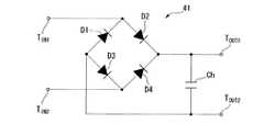
図8に、整流回路41の回路構成例を示す。本例の整流回路41は、ダイオードD1〜D4で構成されたダイオードブリッジと、このダイオードブリッジの出力端子TOUT1およびTOUT2の間に設けられたコンデンサCHにより構成されている。整流回路の入力端子TIN1およびTIN2にはそれぞれ、静電誘導型発電素子の第一の電極11および第二の電極21が接続されている。
整流回路41では、静電誘導型発電素子から入力される交流電力がダイオードブリッジで全波整流され、かつコンデンサCHで平滑されて、直流電力として出力される。
なお、ここでは全波整流用の回路構成例を示したが、半波整流用の回路構成としてもよい。FIG. 8 shows a circuit configuration example of the
In the
Although an example of a circuit configuration for full-wave rectification is shown here, a circuit configuration for half-wave rectification may be used.
下部ユニットBは、固定部材23の凹部に固定電極部20を取り付け、切り欠き部に電力変換回路部4を取り付けることにより構成される。このとき、固定電極部20は、第二の電極21の櫛歯部分のラインの長手方向が、可動電極部20の振動方向Dに交差するように、つまり第一の電極11の櫛歯部分のラインの長手方向と一致するように取り付けられる。
上述したように、上部ユニットAの可動電極部10は、枠部材14の枠内で一定方向(図5〜7中の矢印D方向)に往復運動(振動)できるようになっている。この上部ユニットAの枠部材14を、下部ユニットBの固定部材23上に固定することで、エレクトレット12と第二の電極21とが一定の間隔を開けて対向する。The lower unit B is configured by attaching the fixed
As described above, the
振動発電器1の外形寸法は、特に限定されず、必要とされる電力量、振動発電器1を取り付ける分配管202の大きさ、センサ102の大きさ等に応じて適宜設定できる。振動発電器1を取り付ける分配管202の大きさ、センサ102の大きさを考慮すると、振動発電器1の厚さ(固定部材23の厚さ+枠部材14の厚さ)は、3〜20mmが好ましく、横幅(振動方向Dにおける長さ)および縦幅(振動方向Dに対して垂直方向における長さ)は、それぞれ、5〜30mmが好ましい。 The external dimensions of the
<電源部101の動作>
電源部101においては、分配管202の振動によって振動発電器1が振動すると、静電誘導型発電素子3で交流電力が発電される。すなわち、分配管202が振動すると、これに取り付けられた振動発電器1全体が振動するが、下部ユニットBの固定電極部20よりも上部ユニットAの可動電極部10の方が、振動の幅が大きい。そのため相対的には、可動電極部10が固定電極部20に対して平行に、一定方向(図5〜7中の矢印D方向)に振動していることとなる。
固定電極部20の第二の電極21は、可動電極部10が振動していない状態では、可動電極部10のエレクトレット12と対向する位置にある。このとき、第二の電極21では、対向する位置にあるエレクトレット12の表面電荷によって、エレクトレット12の表面電荷とは逆の極性を持つ電荷が静電誘導される。可動電極部10が振動し、エレクトレット12が移動してエレクトレット12と第二の電極21との重なり部分の面積が減少すると、先に誘導された電荷に対向する逆電荷が無くなり、第二の電極21の電荷の量が減少する。エレクトレット12の位置が元の位置に戻り、第二の電極21との重なり部分の面積が増大すると、再度電荷が静電誘導され、第二の電極21の電荷の量が増大する。このように、第二の電極21とエレクトレット12と相対的な位置の変化により第二の電極21の電荷の量が変化すると、生じた電位差を打ち消すために電流が流れる。この繰り返しを電圧の波として取り出すことで交流電力が得られる。
静電誘導型発電素子3で発電された交流電力は、電力変換回路部4の整流回路41で整流され、直流電力として電力変換回路部4から出力される。出力された直流電力は、電力制御回路2および蓄電部5を介して制御部105に供給されて、センサ102、通信部103、制御部105等を駆動させるための電力(駆動電力)として消費される。<Operation of
In the
The
The AC power generated by the electrostatic induction
振動発電器1によれば、その外形寸法を、分配管202に設置可能な大きさまで小型化した場合でも、分配管202の振動によって、センサノード100の駆動に充分な電力が得られる。
分配管202は、水の流通、配管内に流体を流通させるために設置されているモーター、コンプレッサー等の振動によって常時数Hz以上、数10Hz以下の周波数で振動している。分配管202の直径は家庭用で5〜10cm程度であり、これに取り付ける振動発電器の大きさは、10mm×10mm〜30mm×30mmが適当である。このような大きさでも、上記構成の振動発電器1によれば、上記の低周波数の振動で10〜100μW程度の電力が得られる。センサノード100の消費電力は、1〜50μW程度であるため、振動発電器1以外の電源を設けなくても充分に駆動する。According to the
The
ここで、振動発電器1の最大発電出力Pmaxは、以下の数式で表すことができる。
Pmax=2πσ2nAf/{εε0/d×(εg/d+1)}
[式中、σはエレクトレット12の表面電荷密度、nは極数(第一の基板13の振動方向Dに配置された第二の電極21の数(つまりエレクトレット12の数))、Aはエレクトレット12と第二の電極21との最大重なり面積、fはエレクトレット12の往復運動の周波数、εは比誘電率、ε0は真空の誘電率、dはエレクトレット12の厚さ、gはエレクトレット12と第二の電極21との距離である。]Here, the maximum power generation output Pmax of the
Pmax = 2πσ2 nAf / {εε0 / d × (εg / d + 1)}
[In the formula, σ is the surface charge density of the
上記数式に示されるように、エレクトレット12の表面積(複数の場合は合計の表面積)が同じである場合、エレクトレット12の表面電荷密度が高いほど、または振動方向Dにおけるエレクトレット12の数が多いほど、発電出力も大きくなる。従来、エレクトレットの材料としてはシリコン酸化膜、シリコン窒化膜等の無機材料が汎用されているが、このような無機材料の場合、強度等の点から、厚さdを2μm以上とすることは難しく、微細加工も難しい。そのため、発電出力を大きくすることが難しく、センサノード100の消費電力をエレクトレットのみで賄うことが難しい。
これに対し、本発明で用いられる樹脂膜(A)は、含フッ素重合体(a)または材料(a’)を含有することにより、高い電荷保持性能を有しており、樹脂膜(A)に電荷を注入してなるエレクトレットは高い表面電荷密度を有する。また、たとえば厚さ10μm以上のエレクトレット12を容易に形成できる。また、シリコン酸化膜やシリコン窒化膜に比べてより微細な加工が可能である。そのため、高い発電出力が得られ、センサノード100の駆動に必要な電力を充分に賄うことができる。As shown in the above formula, when the surface area of the electret 12 (the total surface area in the case of multiple electrets) is the same, the higher the surface charge density of the
On the other hand, the resin film (A) used in the present invention has high charge retention performance by containing the fluoropolymer (a) or the material (a ′), and the resin film (A) The electret formed by injecting electric charges into has a high surface charge density. For example, the
<樹脂膜(A)>
樹脂膜(A)は、主鎖に脂肪族環を有する含フッ素重合体(a)または該含フッ素重合体(a)に由来する材料(a’)を含有する。
材料(a’)としては、詳しくは後述するが、含フッ素重合体(a)と含フッ素重合体(a)以外の他の成分との混合物、含フッ素重合体(a)と含フッ素重合体(a)以外の他の成分との反応生成物、等が挙げられる。樹脂膜(A)が前記反応生成物を含む場合、該樹脂膜(A)中には、前記反応生成物の形成に用いた含フッ素重合体(a)または他の成分の一部が未反応のまま残留していてもよい。<Resin film (A)>
The resin film (A) contains a fluoropolymer (a) having an aliphatic ring in the main chain or a material (a ′) derived from the fluoropolymer (a).
The material (a ′), which will be described in detail later, is a mixture of the fluoropolymer (a) and other components other than the fluoropolymer (a), the fluoropolymer (a) and the fluoropolymer. The reaction product with other components other than (a), etc. are mentioned. When the resin film (A) contains the reaction product, the fluoropolymer (a) used for forming the reaction product or a part of other components is unreacted in the resin film (A). It may remain as it is.
[含フッ素重合体(a)]
含フッ素重合体(a)は、主鎖に脂肪族環を有する含フッ素重合体である。
ここで、「含フッ素重合体」は、その構造中にフッ素原子を有する重合体である。
含フッ素重合体(a)において、フッ素原子は、主鎖を構成する炭素原子に結合していてもよく、側鎖に結合していてもよい。低吸水率・低誘電率で絶縁破壊電圧が高く、体積抵抗率の高いエレクトレット化に適していることから、フッ素原子が、主鎖を構成する炭素原子に結合していることが好ましい。[Fluoropolymer (a)]
The fluorinated polymer (a) is a fluorinated polymer having an aliphatic ring in the main chain.
Here, the “fluorinated polymer” is a polymer having a fluorine atom in its structure.
In the fluorine-containing polymer (a), the fluorine atom may be bonded to the carbon atom constituting the main chain or may be bonded to the side chain. The fluorine atom is preferably bonded to the carbon atom constituting the main chain because it is suitable for electretization with a low water absorption and low dielectric constant, high dielectric breakdown voltage, and high volume resistivity.
「主鎖に脂肪族環を有する」とは、脂肪族環の環骨格を構成する炭素原子のうち、少なくとも1つが、含フッ素重合体(a)の主鎖を構成する炭素原子であることを意味する。
たとえば含フッ素重合体(a)が、重合性二重結合を有する単量体の重合により得られたものである場合、重合に用いられた単量体が有する重合性二重結合に由来する炭素原子のうちの少なくとも1つが、前記主鎖を構成する炭素原子となる。たとえば含フッ素重合体(a)が、後述するような環状単量体を重合させて得た含フッ素重合体の場合は、該環状単量体が有する重合性二重結合を構成する2個の炭素原子が主鎖を構成する炭素原子となる。また、2個の重合性二重結合を有する単量体を環化重合させて得た含フッ素重合体の場合は、2個の重合性二重結合を構成する4個の炭素原子のうちの少なくとも2個が主鎖を構成する炭素原子となる。“Having an aliphatic ring in the main chain” means that at least one of the carbon atoms constituting the ring skeleton of the aliphatic ring is a carbon atom constituting the main chain of the fluoropolymer (a). means.
For example, when the fluoropolymer (a) is obtained by polymerization of a monomer having a polymerizable double bond, carbon derived from the polymerizable double bond of the monomer used for the polymerization At least one of the atoms becomes a carbon atom constituting the main chain. For example, when the fluorine-containing polymer (a) is a fluorine-containing polymer obtained by polymerizing a cyclic monomer as described later, two polymerizable double bonds constituting the cyclic monomer are included. The carbon atom becomes the carbon atom constituting the main chain. Further, in the case of a fluorinated polymer obtained by cyclopolymerizing a monomer having two polymerizable double bonds, among the four carbon atoms constituting the two polymerizable double bonds At least two are carbon atoms constituting the main chain.
「脂肪族環」とは、芳香族性を有さない環を示す。脂肪族環は、飽和であってもよく、不飽和であってもよい。脂肪族環は、環骨格が、炭素原子のみから構成される炭素環構造のものであってもよく、環骨格に、炭素原子以外の原子(ヘテロ原子)を含む複素環構造のものであってもよい。該ヘテロ原子としては酸素原子、窒素原子等が挙げられる。
脂肪族環の環骨格を構成する原子の数は、4〜7個が好ましく、5〜6個であることがより好ましい。すなわち、脂肪族環は4〜7員環であることが好ましく、5〜6員環であることがより好ましい。
脂肪族環は置換基を有していてもよく、有さなくてもよい。「置換基を有していてもよい」とは、該脂肪族環の環骨格を構成する原子に置換基(水素原子以外の原子または基)が結合してもよいことを意味する。“Aliphatic ring” refers to a ring having no aromaticity. The aliphatic ring may be saturated or unsaturated. The aliphatic ring may have a carbocyclic structure in which the ring skeleton is composed only of carbon atoms, and has a heterocyclic structure that includes atoms other than carbon atoms (heteroatoms) in the ring skeleton. Also good. Examples of the hetero atom include an oxygen atom and a nitrogen atom.
The number of atoms constituting the ring skeleton of the aliphatic ring is preferably 4 to 7, and more preferably 5 to 6. That is, the aliphatic ring is preferably a 4- to 7-membered ring, and more preferably a 5- to 6-membered ring.
The aliphatic ring may or may not have a substituent. The phrase “which may have a substituent” means that a substituent (an atom or group other than a hydrogen atom) may be bonded to an atom constituting the ring skeleton of the aliphatic ring.
脂肪族環は、非含フッ素脂肪族環であってもよく、含フッ素脂肪族環であってもよい。
非含フッ素脂肪族環は、構造中にフッ素原子を含まない脂肪族環である。非含フッ素脂肪族環として、具体的には、飽和または不飽和の脂肪族炭化水素環、該脂肪族炭化水素環における炭素原子の一部が酸素原子、窒素原子等のヘテロ原子で置換された脂肪族複素環等が挙げられる。
含フッ素脂肪族環は、構造中にフッ素原子を含む脂肪族環である。含フッ素脂肪族環としては、脂肪族環の環骨格を構成する炭素原子に、フッ素原子を含む置換基(以下、含フッ素基という。)が結合した脂肪族環が挙げられる。含フッ素基としては、フッ素原子、ペルフルオロアルキル基、ペルフルオロアルコキシ基、=CF2等が挙げられる。
該含フッ素脂肪族環または非含フッ素脂肪族環は、含フッ素基以外の置換基を有していてもよい。
脂肪族環としては、電荷保持性能に優れることから、含フッ素脂肪族環が好ましい。The aliphatic ring may be a non-fluorinated aliphatic ring or a fluorinated aliphatic ring.
The non-fluorinated aliphatic ring is an aliphatic ring that does not contain a fluorine atom in the structure. Specifically, as the non-fluorinated aliphatic ring, a saturated or unsaturated aliphatic hydrocarbon ring, and a part of carbon atoms in the aliphatic hydrocarbon ring is substituted with a hetero atom such as an oxygen atom or a nitrogen atom. An aliphatic heterocyclic ring etc. are mentioned.
The fluorine-containing aliphatic ring is an aliphatic ring containing a fluorine atom in the structure. Examples of the fluorinated aliphatic ring include an aliphatic ring in which a substituent containing a fluorine atom (hereinafter referred to as a fluorinated group) is bonded to a carbon atom constituting the ring skeleton of the aliphatic ring. Examples of the fluorine-containing group include a fluorine atom, a perfluoroalkyl group, a perfluoroalkoxy group, and ═CF2 .
The fluorine-containing aliphatic ring or non-fluorine-containing aliphatic ring may have a substituent other than the fluorine-containing group.
As the aliphatic ring, a fluorine-containing aliphatic ring is preferable because of excellent charge retention performance.
好ましい含フッ素重合体(a)として、下記含フッ素環状重合体(I)、含フッ素環状重合体(II)が挙げられる。
含フッ素環状重合体(I):環状含フッ素単量体に基づく単位を有する重合体。
含フッ素環状重合体(II):ジエン系含フッ素単量体の環化重合により形成される単位を有する重合体。
「環状重合体」とは環状構造を有する重合体を意味する。
「単位」は、重合体を構成する繰り返し単位を意味する。
以下、式(1)で表される化合物を「化合物(1)」とも記す。他の式で表される単位、化合物等についても同様に記し、たとえば式(3−1)で表される単位を「単位(3−1)」とも記す。Preferred fluorine-containing polymers (a) include the following fluorine-containing cyclic polymers (I) and fluorine-containing cyclic polymers (II).
Fluorinated cyclic polymer (I): a polymer having units based on a cyclic fluorinated monomer.
Fluorine-containing cyclic polymer (II): a polymer having units formed by cyclopolymerization of a diene fluorine-containing monomer.
“Cyclic polymer” means a polymer having a cyclic structure.
“Unit” means a repeating unit constituting a polymer.
Hereinafter, the compound represented by the formula (1) is also referred to as “compound (1)”. The same applies to units, compounds and the like represented by other formulas. For example, the unit represented by formula (3-1) is also referred to as “unit (3-1)”.
含フッ素環状重合体(I)は、環状含フッ素単量体に基づく単位を有する。
「環状含フッ素単量体」とは、含フッ素脂肪族環を構成する炭素原子間に重合性二重結合を有する単量体、または、含フッ素脂肪族環を構成する炭素原子と含フッ素脂肪族環外の炭素原子との間に重合性二重結合を有する単量体である。
環状含フッ素単量体としては、下記の化合物(1)または化合物(2)が好ましい。The fluorinated cyclic polymer (I) has units based on a cyclic fluorinated monomer.
“Cyclic fluorine-containing monomer” means a monomer having a polymerizable double bond between carbon atoms constituting a fluorine-containing aliphatic ring, or a carbon atom constituting a fluorine-containing aliphatic ring and a fluorine-containing fat. It is a monomer having a polymerizable double bond with a carbon atom outside the group ring.
As the cyclic fluorine-containing monomer, the following compound (1) or compound (2) is preferable.
X1、X2、X3、X4、Y1およびY2におけるペルフルオロアルキル基は、炭素数が1〜7であることが好ましく、炭素数が1〜4であることがより好ましい。該ペルフルオロアルキル基は、直鎖状または分岐鎖状が好ましく、直鎖状がより好ましい。具体的には、トリフルオロメチル基、ペンタフルオロエチル基、ヘプタフルオロプロピル基等が挙げられ、特にトリフルオロメチル基が好ましい。
X1、X2、X3、X4、Y1およびY2におけるペルフルオロアルコキシ基としては、前記ペルフルオロアルキル基に酸素原子(−O−)が結合したものが挙げられ、トリフルオロメトキシ基が特に好ましい。
前記ペルフルオロアルキル基またはペルフルオロアルコキシ基の炭素数が2以上である場合、該ペルフルオロアルキル基またはペルフルオロアルコキシ基の炭素原子間に酸素原子(−O−)が介在してもよい。The perfluoroalkyl group in X1 , X2 , X3 , X4 , Y1 and Y2 preferably has 1 to 7 carbon atoms, and more preferably 1 to 4 carbon atoms. The perfluoroalkyl group is preferably linear or branched, and more preferably linear. Specific examples include a trifluoromethyl group, a pentafluoroethyl group, a heptafluoropropyl group, and the like, and a trifluoromethyl group is particularly preferable.
Examples of the perfluoroalkoxy group in X1 , X2 , X3 , X4 , Y1 and Y2 include those in which an oxygen atom (—O—) is bonded to the perfluoroalkyl group, and a trifluoromethoxy group is particularly preferred. preferable.
When the perfluoroalkyl group or perfluoroalkoxy group has 2 or more carbon atoms, an oxygen atom (—O—) may be interposed between the carbon atoms of the perfluoroalkyl group or perfluoroalkoxy group.
式(1)中、X1は、フッ素原子であることが好ましい。
X2は、フッ素原子、トリフルオロメチル基、または炭素数1〜4のペルフルオロアルコキシ基であることが好ましく、フッ素原子またはトリフルオロメトキシ基であることがより好ましい。
X3およびX4は、それぞれ独立に、フッ素原子または炭素数1〜4のペルフルオロアルキル基であることが好ましく、フッ素原子またはトリフルオロメチル基であることがより好ましい。
X3およびX4は相互に結合して環を形成してもよい。前記環の環骨格を構成する原子の数は、4〜7個が好ましく、5〜6個であることがより好ましい。
化合物(1)の好ましい具体例として、化合物(1−1)〜(1−5)が挙げられる。In formula (1), X1 is preferably a fluorine atom.
X2 is preferably a fluorine atom, a trifluoromethyl group, or a perfluoroalkoxy group having 1 to 4 carbon atoms, and more preferably a fluorine atom or a trifluoromethoxy group.
X3 and X4 are each independently preferably a fluorine atom or a perfluoroalkyl group having 1 to 4 carbon atoms, and more preferably a fluorine atom or a trifluoromethyl group.
X3 and X4 may be bonded to each other to form a ring. The number of atoms constituting the ring skeleton of the ring is preferably 4 to 7, and more preferably 5 to 6.
Preferable specific examples of compound (1) include compounds (1-1) to (1-5).
式(2)中、Y1およびY2は、それぞれ独立に、フッ素原子、炭素数1〜4のペルフルオロアルキル基または炭素数1〜4のペルフルオロアルコキシ基が好ましく、フッ素原子またはトリフルオロメチル基がより好ましい。
化合物(2)の好ましい具体例として、化合物(2−1)〜(2−2)が挙げられる。In Formula (2), Y1 and Y2 are each independently preferably a fluorine atom, a C 1-4 perfluoroalkyl group or a C 1-4 perfluoroalkoxy group, and a fluorine atom or a trifluoromethyl group is preferred. More preferred.
Preferable specific examples of compound (2) include compounds (2-1) to (2-2).
含フッ素環状重合体(I)は、上記環状含フッ素単量体により形成される単位のみから構成されてもよく、該単位と、それ以外の他の単位とを有する共重合体であってもよい。
ただし、該含フッ素環状重合体(I)中、環状含フッ素単量体に基づく単位の割合は、該含フッ素環状重合体(I)を構成する全繰り返し単位の合計に対し、20モル%以上が好ましく、40モル%以上がより好ましく、100モル%であってもよい。
該他の単量体としては、上記環状含フッ素単量体と共重合可能なものであればよく、特に限定されない。具体的には、ジエン系含フッ素単量体、側鎖に反応性官能基を有する単量体、テトラフルオロエチレン、クロロトリフルオロエチレン、ペルフルオロ(メチルビニルエーテル)等が挙げられる。ジエン系含フッ素単量体としては、後述する含フッ素環状重合体(II)の説明で挙げるものと同様のものが挙げられる。側鎖に反応性官能基を有する単量体としては、重合性二重結合および反応性官能基を有する単量体が挙げられる。重合性二重結合としては、CF2=CF−、CF2=CH−、CH2=CF−、CFH=CF−、CFH=CH−、CF2=C−、CF=CF−等が挙げられる。反応性官能基としては、後述する含フッ素環状重合体(II)の説明で挙げるものと同様のものが挙げられる。
なお環状含フッ素単量体とジエン系含フッ素単量体との共重合により得られる重合体は含フッ素環状重合体(I)として考える。The fluorinated cyclic polymer (I) may be composed only of units formed by the cyclic fluorinated monomer, or may be a copolymer having the units and other units. Good.
However, the proportion of units based on the cyclic fluorinated monomer in the fluorinated cyclic polymer (I) is 20 mol% or more based on the total of all repeating units constituting the fluorinated cyclic polymer (I). Is preferable, 40 mol% or more is more preferable, and 100 mol% may be sufficient.
The other monomer is not particularly limited as long as it is copolymerizable with the cyclic fluorine-containing monomer. Specific examples include diene fluorine-containing monomers, monomers having a reactive functional group in the side chain, tetrafluoroethylene, chlorotrifluoroethylene, perfluoro (methyl vinyl ether), and the like. Examples of the diene-based fluorine-containing monomer include the same as those mentioned in the description of the fluorine-containing cyclic polymer (II) described later. Examples of the monomer having a reactive functional group in the side chain include monomers having a polymerizable double bond and a reactive functional group. The polymerizable doublebond, CF 2 = CF-, CF 2 = CH-,
A polymer obtained by copolymerization of a cyclic fluorine-containing monomer and a diene-based fluorine-containing monomer is considered as a fluorine-containing cyclic polymer (I).
含フッ素環状重合体(II)は、ジエン系含フッ素単量体の環化重合により形成される単位を有する。
「ジエン系含フッ素単量体」とは、2個の重合性二重結合およびフッ素原子を有する単量体である。該重合性二重結合としては、特に限定されないが、ビニル基、アリル基、アクリロイル基、メタクリロイル基が好ましい。
ジエン系含フッ素単量体としては、下記化合物(3)が好ましい。
CF2=CF−Q−CF=CF2 ・・・(3)。
式(3)中、Qは、エーテル性酸素原子を有していてもよく、フッ素原子の一部がフッ素原子以外のハロゲン原子で置換されていてもよい炭素数1〜5、好ましくは1〜3の、分岐を有してもよいペルフルオロアルキレン基である。該フッ素以外のハロゲン原子としては、塩素原子、臭素原子等が挙げられる。
Qはエーテル性酸素原子を有するペルフルオロアルキレン基であることが好ましい。その場合、該ペルフルオロアルキレン基におけるエーテル性酸素原子は、該基の一方の末端に存在していてもよく、該基の両末端に存在していてもよく、該基の炭素原子間に存在していてもよい。環化重合性の点から、該基の一方の末端に存在していることが好ましい。The fluorinated cyclic polymer (II) has units formed by cyclopolymerization of a diene fluorinated monomer.
The “diene fluorine-containing monomer” is a monomer having two polymerizable double bonds and fluorine atoms. Although it does not specifically limit as this polymerizable double bond, A vinyl group, an allyl group, an acryloyl group, and a methacryloyl group are preferable.
As the diene fluorine-containing monomer, the following compound (3) is preferable.
CF 2 = CF-Q-CF =
In formula (3), Q may have an etheric oxygen atom, and a part of fluorine atoms may be substituted with a halogen atom other than fluorine atoms, preferably 1 to 5 carbon atoms, preferably 1 to 1 carbon atoms. 3 is a perfluoroalkylene group which may have a branch. Examples of halogen atoms other than fluorine include chlorine atom and bromine atom.
Q is preferably a perfluoroalkylene group having an etheric oxygen atom. In that case, the etheric oxygen atom in the perfluoroalkylene group may be present at one end of the group, may be present at both ends of the group, and is present between the carbon atoms of the group. It may be. From the viewpoint of cyclopolymerizability, it is preferably present at one end of the group.
化合物(3)の具体例としては、下記化合物が挙げられる。
CF2=CFOCF2CF=CF2、
CF2=CFOCF(CF3)CF=CF2、
CF2=CFOCF2CF2CF=CF2、
CF2=CFOCF2CF(CF3)CF=CF2、
CF2=CFOCF(CF3)CF2CF=CF2、
CF2=CFOCFClCF2CF=CF2、
CF2=CFOCCl2CF2CF=CF2、
CF2=CFOCF2OCF=CF2、
CF2=CFOC(CF3)2OCF=CF2、
CF2=CFOCF2CF(OCF3)CF=CF2、
CF2=CFCF2CF=CF2、
CF2=CFCF2CF2CF=CF2、
CF2=CFCF2OCF2CF=CF2。Specific examples of the compound (3) include the following compounds.
CF2 = CFOCF2 CF = CF2 ,
CF2 = CFOCF (CF3 ) CF═CF2 ,
CF2 = CFOCF2 CF2 CF = CF2 ,
CF2 = CFOCF2 CF (CF3 ) CF═CF2 ,
CF2 = CFOCF (CF3 ) CF2 CF = CF2 ,
CF2 = CFOCFClCF2 CF = CF2 ,
CF 2 = CFOCCl 2 CF 2 CF =
CF2 = CFOCF2 OCF = CF2 ,
CF 2 = CFOC (CF 3) 2 OCF =
CF2 = CFOCF2 CF (OCF3 ) CF═CF2 ,
CF2 = CFCF2 CF = CF2 ,
CF2 = CFCF2 CF2 CF = CF2 ,
CF 2 = CFCF 2 OCF 2 CF =
化合物(3)の環化重合により形成される単位として、下記単位(3−1)〜(3−4)等が挙げられる。 Examples of the unit formed by the cyclopolymerization of the compound (3) include the following units (3-1) to (3-4).
含フッ素重合体(a)は、反応性官能基を有することが好ましい。
「反応性官能基」とは、加熱等を行った際に、当該含フッ素重合体(a)の分子間、または含フッ素重合体(a)とともに配合されている他の成分と反応して結合を形成し得る反応性を有する基を意味する。
たとえば該他の成分として、後述するシランカップリング剤または極性官能基を2個以上有する分子量50〜2,000の化合物(ただしシランカップリング剤は除く。)(以下、多価極性化合物という。)を混合し、それらを反応させて反応生成物とする場合は、含フッ素重合体(a)が、シランカップリング剤が有する官能基または多価極性化合物が有する極性官能基と反応し得る反応性官能基を有することが好ましい。
含フッ素重合体(a)が有する反応性官能基としては、重合体中への導入のしやすさ、シランカップリング剤または多価極性化合物との相互作用の強さ等を考慮すると、カルボキシ基、酸ハライド基、アルコキシカルボニル基、カルボニルオキシ基、カーボネート基、スルホ基、ホスホノ基、ヒドロキシ基、チオール基、シラノール基およびアルコキシシリル基からなる群から選ばれる少なくとも1種が好ましく、カルボキシ基またはアルコキシカルボニル基が特に好ましい。
反応性官能基は、含フッ素重合体(a)の主鎖末端に結合していてもよく、側鎖に結合していてもよい。The fluorinated polymer (a) preferably has a reactive functional group.
The “reactive functional group” is bonded by reacting with other components blended between the molecules of the fluoropolymer (a) or together with the fluoropolymer (a) when heating or the like is performed. Means a reactive group capable of forming.
For example, as the other component, a silane coupling agent described later or a compound having a molecular weight of 50 to 2,000 having two or more polar functional groups (excluding the silane coupling agent) (hereinafter referred to as a polyvalent polar compound). When the fluorinated polymer (a) is reacted with the functional group possessed by the silane coupling agent or the polar functional group possessed by the polyvalent polar compound, It preferably has a functional group.
As the reactive functional group possessed by the fluoropolymer (a), in view of ease of introduction into the polymer, strength of interaction with the silane coupling agent or the polyvalent polar compound, etc., a carboxy group , An acid halide group, an alkoxycarbonyl group, a carbonyloxy group, a carbonate group, a sulfo group, a phosphono group, a hydroxy group, a thiol group, a silanol group, and an alkoxysilyl group, preferably at least one selected from the group consisting of a carboxy group or an alkoxy group A carbonyl group is particularly preferred.
The reactive functional group may be bonded to the end of the main chain of the fluoropolymer (a) or may be bonded to a side chain.
含フッ素重合体(a)の比誘電率は1.8〜8が好ましく、1.8〜5がより好ましく、1.8〜3がさらに好ましく、1.8〜2.7が特に好ましく、1.8〜2.3が最も好ましい。該比誘電率が上記範囲の下限値以上であると、エレクトレットとして蓄え得る電荷量が高く、上限値以下であると、電気絶縁性、およびエレクトレットとしての電荷保持安定性に優れる。該比誘電率は、ASTM D150に準拠し、周波数1MHzにおいて測定される。
また、樹脂膜(A)はエレクトレットとしての電荷保持を担う部分であることから、含フッ素重合体(a)としては、体積固有抵抗が高く、絶縁破壊強度が大きいものが好ましい。
含フッ素重合体(a)の体積固有抵抗は1010〜1020Ωcmが好ましく、1016〜1019Ωcmがより好ましい。該体積固有抵抗は、ASTM D257により測定される。
含フッ素重合体(a)の絶縁破壊強度は10〜25kV/mmが好ましく、15〜22kV/mmがより好ましい。該絶縁破壊強度は、ASTM D149により測定される。
含フッ素重合体(a)の屈折率は、基板との屈折率差を小さくし、複屈折等による光の干渉を抑え、透明性を確保する点から、1.2〜2が好ましく、1.2〜1.5が特に好ましい。The relative dielectric constant of the fluoropolymer (a) is preferably 1.8 to 8, more preferably 1.8 to 5, further preferably 1.8 to 3, particularly preferably 1.8 to 2.7. .8 to 2.3 is most preferable. When the relative dielectric constant is not less than the lower limit of the above range, the amount of charge that can be stored as an electret is high, and when it is not more than the upper limit, the electrical insulation and the charge retention stability as an electret are excellent. The relative dielectric constant is measured at a frequency of 1 MHz in accordance with ASTM D150.
In addition, since the resin film (A) is a part responsible for charge retention as an electret, the fluoropolymer (a) preferably has a high volume resistivity and a high dielectric breakdown strength.
The volume resistivity of the fluoropolymer (a) is preferably 1010 to 1020 Ωcm, and more preferably 1016 to 1019 Ωcm. The volume resistivity is measured according to ASTM D257.
The dielectric breakdown strength of the fluoropolymer (a) is preferably 10 to 25 kV / mm, and more preferably 15 to 22 kV / mm. The dielectric breakdown strength is measured according to ASTM D149.
The refractive index of the fluorinated polymer (a) is preferably 1.2 to 2 from the viewpoint of reducing the difference in refractive index from the substrate, suppressing light interference due to birefringence and the like, and ensuring transparency. 2 to 1.5 is particularly preferable.
含フッ素重合体(a)の重量平均分子量(Mw)は、5万以上が好ましく、15万以上がより好ましく、20万以上がさらに好ましく、25万以上が特に好ましい。Mwが5万以上であると、製膜しやすい。特に20万以上であると、膜の耐熱性が向上し、エレクトレットとした際、保持した電荷の熱安定性が向上する。一方、Mwが大きすぎると、溶媒に溶けにくくなり、製膜プロセスが制限される等の問題が生じるおそれがある。したがって、含フッ素重合体(a)のMwは、100万以下が好ましく、85万以下がより好ましく、65万以下がさらに好ましく、55万以下が特に好ましい。
本明細書において、含フッ素重合体(a)のMwは、日本化学会誌、2001,NO.12,P.661に記載される、Mwと固有粘度[η](30℃)との関係式([η]=1.7×10⁻⁴×Mw0.60)を用いて算出される値である。
固有粘度[η](30℃)(単位:dl/g)は、30℃で、ペルフルオロ(2−ブチルテトラヒドロフラン)を溶媒として、ウベローデ型粘度計により測定される値である。The weight average molecular weight (Mw) of the fluoropolymer (a) is preferably 50,000 or more, more preferably 150,000 or more, further preferably 200,000 or more, and particularly preferably 250,000 or more. When Mw is 50,000 or more, film formation is easy. In particular, when it is 200,000 or more, the heat resistance of the film is improved, and the thermal stability of the retained charge is improved when an electret is formed. On the other hand, if Mw is too large, it is difficult to dissolve in a solvent, and there is a possibility that problems such as limitation of the film forming process may occur. Therefore, Mw of the fluoropolymer (a) is preferably 1 million or less, more preferably 850,000 or less, further preferably 650,000 or less, and particularly preferably 550,000 or less.
In the present specification, Mw of the fluorine-containing polymer (a) is the chemical journal of the Chemical Society of Japan, 2001, NO. 12, p. It is a value calculated using the relational expression ([η] = 1.7 × 10⁻⁴ × Mw0.60 ) between Mw and intrinsic viscosity [η] (30 ° C.) described in 661.
Intrinsic viscosity [η] (30 ° C.) (unit: dl / g) is a value measured by an Ubbelohde viscometer at 30 ° C. using perfluoro (2-butyltetrahydrofuran) as a solvent.
含フッ素重合体(a)は、前述した単量体を重合させることにより合成したものを用いてもよく、市販品を用いてもよい。
主鎖にエーテル性酸素原子を含む含フッ素脂肪族環を有し、主鎖の末端にカルボキシ基またはアルコキシカルボニル基を有する含フッ素重合体の市販品としては、CYTOP(登録商標、旭硝子社製)が挙げられる。As the fluoropolymer (a), one synthesized by polymerizing the above-described monomers may be used, or a commercially available product may be used.
CYTOP (registered trademark, manufactured by Asahi Glass Co., Ltd.) is a commercially available fluoropolymer having a fluorine-containing aliphatic ring containing an etheric oxygen atom in the main chain and having a carboxy group or an alkoxycarbonyl group at the end of the main chain. Is mentioned.
[材料(a’)]
材料(a’)としては、上述したように、含フッ素重合体(a)と含フッ素重合体(a)以外の他の成分との混合物、含フッ素重合体(a)と含フッ素重合体(a)以外の他の成分との反応生成物、等が挙げられる。
前記反応生成物としては、たとえば含フッ素重合体(a)および前記他の成分を溶媒に溶解したコーティング液を加熱(溶媒を揮発させて成膜する際のベーク等)した際に、各成分が反応して生成するものが挙げられる。
含フッ素重合体(a)と混合または反応させる他の成分としては、シランカップリング剤または多価極性化合物が好ましく、シランカップリング剤が特に好ましい。これにより、形成される樹脂膜(A)の電荷保持性能(保持した電荷の熱安定性、経時安定性等)が向上する。電荷保持性能の向上効果は、特に、含フッ素重合体(a)が末端基としてカルボキシ基またはアルコキシカルボニル基を有する場合に顕著である。
電荷保持性能の向上効果は、含フッ素重合体(a)とシランカップリング剤または多価極性化合物とがナノ相分離を引き起こし、シランカップリング剤または多価極性化合物由来のナノクラスタ構造が形成され、当該ナノクラスタ構造が、エレクトレットにおける電荷を蓄える部位として機能するためであると推察される。
材料(a’)中、シランカップリング剤または多価極性化合物は、分子同士が反応した状態で存在していてもよい。[Material (a ′)]
As the material (a ′), as described above, a mixture of the fluoropolymer (a) and other components other than the fluoropolymer (a), the fluoropolymer (a) and the fluoropolymer ( Reaction products with other components other than a) and the like can be mentioned.
As the reaction product, for example, when the coating liquid in which the fluoropolymer (a) and the other components are dissolved in a solvent is heated (e.g., when the solvent is evaporated to form a film), each component is What is produced | generated by reacting is mentioned.
As other components to be mixed or reacted with the fluoropolymer (a), a silane coupling agent or a polyvalent polar compound is preferable, and a silane coupling agent is particularly preferable. As a result, the charge retention performance (thermal stability of the retained charge, stability over time, etc.) of the formed resin film (A) is improved. The effect of improving the charge retention performance is particularly remarkable when the fluoropolymer (a) has a carboxy group or an alkoxycarbonyl group as a terminal group.
The effect of improving the charge retention performance is that the fluoropolymer (a) and the silane coupling agent or polypolar compound cause nanophase separation, and a nanocluster structure derived from the silane coupling agent or polypolar compound is formed. The nanocluster structure is presumed to function as a site for storing charges in the electret.
In the material (a ′), the silane coupling agent or the polyvalent polar compound may be present in a state in which molecules react with each other.
シランカップリング剤としては、特に限定されず、従来公知または周知のものを含めて広範囲にわたって利用できる。
シランカップリング剤としては、アミノ基を有するシランカップリング剤が好ましい。
入手の容易性等を考慮すると、特に好ましいシランカップリング剤は、γ−アミノプロピルメチルジエトキシシラン、γ−アミノプロピルメチルジメトキシシラン、γ−アミノプロピルトリメトキシシラン、γ−アミノプロピルトリエトキシシラン、N−(β−アミノエチル)−γ−アミノプロピルトリメトキシシラン、N−(β−アミノエチル)−γ−アミノプロピルメチルジメトキシシラン、およびN−(β−アミノエチル)−γ−アミノプロピルトリエトキシシラン、から選択される1種以上である。It does not specifically limit as a silane coupling agent, It can utilize over a wide range including a conventionally well-known or well-known thing.
As the silane coupling agent, a silane coupling agent having an amino group is preferable.
Considering availability, etc., particularly preferred silane coupling agents are γ-aminopropylmethyldiethoxysilane, γ-aminopropylmethyldimethoxysilane, γ-aminopropyltrimethoxysilane, γ-aminopropyltriethoxysilane, N- (β-aminoethyl) -γ-aminopropyltrimethoxysilane, N- (β-aminoethyl) -γ-aminopropylmethyldimethoxysilane, and N- (β-aminoethyl) -γ-aminopropyltriethoxy One or more selected from silane.
シランカップリング剤は、1種を単独で用いてもよく、2種以上を併用してもよい。
シランカップリング剤の配合量は、含フッ素重合体(a)とシランカップリング剤との合計量に対して、0.1〜20質量%が好ましく、0.3〜10質量%がより好ましく、0.5〜5質量%が最も好ましい。この範囲にあると、含フッ素重合体(a)とともに溶媒に溶解してコーティング液とした際に、容易に均一な溶液とすることができる。A silane coupling agent may be used individually by 1 type, and may use 2 or more types together.
0.1-20 mass% is preferable with respect to the total amount of a fluoropolymer (a) and a silane coupling agent, and, as for the compounding quantity of a silane coupling agent, 0.3-10 mass% is more preferable, 0.5-5 mass% is the most preferable. When it is in this range, when it is dissolved in a solvent together with the fluoropolymer (a) to form a coating solution, a uniform solution can be easily obtained.
多価極性化合物は、極性官能基を2個以上有する分子量50〜2,000の化合物(ただし前記シランカップリング剤は除く。)が好ましい。分子量は100〜2,000がより好ましい。多価極性化合物の分子量が上記範囲の下限値以上であると、分子量が高いために揮発しにくく、製膜後に膜中に残存させることが容易になる。また、上記範囲の上限値以下であると、含フッ素重合体(a)との相溶性が良好になる。
「極性官能基」とは、下記の(1a)および(1b)の何れか一方または両方の特性を有する官能基である。
(1a)電気陰性度の異なる2種類以上の原子を含み、当該官能基中に分極による極性を有する。
(1b)当該官能基と結合した炭素との電気陰性度の差により分極を生じさせる。The polyvalent polar compound is preferably a compound having a molecular weight of 50 to 2,000 having two or more polar functional groups (excluding the silane coupling agent). The molecular weight is more preferably 100 to 2,000. When the molecular weight of the polyvalent polar compound is not less than the lower limit of the above range, the molecular weight is high, so that it is difficult to volatilize and it is easy to remain in the film after film formation. Moreover, compatibility with a fluoropolymer (a) becomes favorable as it is below the upper limit of the said range.
The “polar functional group” is a functional group having one or both of the following properties (1a) and (1b).
(1a) Two or more types of atoms having different electronegativity are included, and the functional group has polarity due to polarization.
(1b) Polarization is caused by the difference in electronegativity with carbon bonded to the functional group.
上記特性(1a)のみを有する極性官能基の具体例としては、ヒドロキシフェニル基等が挙げられる。
上記特性(1b)のみを有する極性官能基の具体例としては、1級アミノ基(−NH2)、2級アミノ基(−NH−)、ヒドロキシ基、チオール基等が挙げられる。
上記特性(1a)および(1b)の両方を有する極性官能基の具体例としては、スルホ基、ホスホノ基、カルボキシ基、アルコキシカルボニル基、酸ハライド基、ホルミル基、イソシアナート基、シアノ基、カルボニルオキシ基(−C(O)−O−)カーボネート基(−O−C(O)−O−)等が挙げられる。Specific examples of the polar functional group having only the above characteristic (1a) include a hydroxyphenyl group.
Specific examples of the polar functional group having only the characteristic (1b) include a primary amino group (—NH2 ), a secondary amino group (—NH—), a hydroxy group, and a thiol group.
Specific examples of the polar functional group having both the above characteristics (1a) and (1b) include sulfo group, phosphono group, carboxy group, alkoxycarbonyl group, acid halide group, formyl group, isocyanate group, cyano group, carbonyl group. And an oxy group (—C (O) —O—) carbonate group (—O—C (O) —O—).
多価極性化合物としては、ペンタン−1,5−ジアミン、ヘキサン−1,6−ジアミン、シクロヘキサン−1,2−ジアミン、シクロヘキサン−1,3−ジアミン、シクロヘキサン−1,4−ジアミン、1,2−ジアミノベンゼン、1,3−ジアミノベンゼン、1,4−ジアミノベンゼン、トリアミノメチルアミン、トリス(2−アミノエチル)アミン、トリス(3−アミノプロピル)アミン、シクロヘキサン−1,3,5−トリアミン、シクロヘキサン−1,2,4−トリアミン、1,3,5−トリアミノベンゼン、1,2,4−トリアミノベンゼン、2,4,6−トリアミノトルエン、1,3,5−トリス(2−アミノエチル)ベンゼン、1,2,4−トリス(2−アミノエチル)ベンゼン、2,4,6−トリス(2−アミノエチル)トルエン、ジエチレントリアミン、トリエチレンテトラミン、テトラエチレンペンタミンおよびポリエチレンイミンからなる群から選ばれる少なくとも1種がより好ましく、トリス(2−アミノエチル)アミン、トリス(3−アミノプロピル)アミン、シクロヘキサン−1,3−ジアミン、ヘキサン−1,6−ジアミン、ジエチレントリアミンおよびポリエチレンイミンからなる群から選ばれる少なくとも1種が最も好ましい。 Examples of the polyvalent polar compound include pentane-1,5-diamine, hexane-1,6-diamine, cyclohexane-1,2-diamine, cyclohexane-1,3-diamine, cyclohexane-1,4-diamine, and 1,2. -Diaminobenzene, 1,3-diaminobenzene, 1,4-diaminobenzene, triaminomethylamine, tris (2-aminoethyl) amine, tris (3-aminopropyl) amine, cyclohexane-1,3,5-triamine , Cyclohexane-1,2,4-triamine, 1,3,5-triaminobenzene, 1,2,4-triaminobenzene, 2,4,6-triaminotoluene, 1,3,5-tris (2 -Aminoethyl) benzene, 1,2,4-tris (2-aminoethyl) benzene, 2,4,6-tris (2-aminoethyl) to More preferred is at least one selected from the group consisting of ene, diethylenetriamine, triethylenetetramine, tetraethylenepentamine and polyethyleneimine, and tris (2-aminoethyl) amine, tris (3-aminopropyl) amine, cyclohexane-1, Most preferred is at least one selected from the group consisting of 3-diamine, hexane-1,6-diamine, diethylenetriamine and polyethyleneimine.
多価極性化合物は、1種を単独で用いてもよく、2種以上を併用してもよい。たとえば、極性官能基を2個有する化合物と、極性官能基を3個以上有する化合物とを混合して用いてもよい。
多価極性化合物の配合量は、含フッ素重合体(a)の配合量の0.01〜30質量%であることが好ましく、0.05〜10質量%であることがより好ましい。該配合量が0.01質量%以上であると、多価極性化合物を配合することによる効果が充分に得られる。該配合量が30質量%以下であると、含フッ素重合体(a)との混和性が良好であり、コーティング液中での分布が均一となる。A polyvalent polar compound may be used individually by 1 type, and may use 2 or more types together. For example, a compound having two polar functional groups and a compound having three or more polar functional groups may be mixed and used.
The blending amount of the polyvalent polar compound is preferably 0.01 to 30% by weight, more preferably 0.05 to 10% by weight, based on the blending amount of the fluoropolymer (a). The effect by mix | blending a polyvalent polar compound as this compounding quantity is 0.01 mass% or more is fully acquired. When the blending amount is 30% by mass or less, the miscibility with the fluoropolymer (a) is good, and the distribution in the coating liquid becomes uniform.
<樹脂膜(A)の形成方法>
樹脂膜(A)の形成方法としては特に限定されず、公知の方法を利用できる。たとえば、第一の電極11が形成された第一の基板13の、第一の電極11側の表面上にコーティング膜を形成し、該コーティング膜を、第一の電極11に対応するパターンにパターニングする方法が挙げられる。
コーティング膜の形成方法としては、たとえば、含フッ素重合体(a)を溶媒に溶解してなるコーティング液、または含フッ素重合体(a)と該含フッ素重合体(a)以外の他の成分とを溶媒に溶解してなるコーティング液を用いてコーティング膜を製膜する方法が挙げられる。前記他の成分としては、上述したとおり、シランカップリング剤または多価極性化合物が好ましく、シランカップリング剤が特に好ましい。<Method for Forming Resin Film (A)>
It does not specifically limit as a formation method of a resin film (A), A well-known method can be utilized. For example, a coating film is formed on the surface of the
As a method for forming the coating film, for example, a coating solution obtained by dissolving the fluoropolymer (a) in a solvent, or the fluoropolymer (a) and other components other than the fluoropolymer (a) There is a method of forming a coating film using a coating solution obtained by dissolving in a solvent. As said other component, as above-mentioned, a silane coupling agent or a polyvalent polar compound is preferable, and a silane coupling agent is especially preferable.
溶媒としては、少なくとも含フッ素重合体(a)を溶解する溶媒が用いられ、他の成分を含む場合、前記含フッ素重合体(a)を溶解する溶媒が、該他の成分を溶解するものであれば、該溶媒単独で均一な溶液とすることができる。また、該他の成分を溶解する他の溶媒を併用してもよい。
溶媒として具体的には、プロトン性溶媒、非プロトン性溶媒等が挙げられ、それらの中から当該コーティング液に配合される成分を溶解するものを適宜選択すればよい。
「プロトン性溶媒」とは、プロトン供与性を有する溶媒である。「非プロトン性溶媒」とは、プロトン供与性を有さない溶媒である。As the solvent, a solvent that dissolves at least the fluoropolymer (a) is used, and when it contains other components, the solvent that dissolves the fluoropolymer (a) dissolves the other components. If present, the solvent alone can be a uniform solution. Moreover, you may use together the other solvent which melt | dissolves this other component.
Specific examples of the solvent include a protic solvent, an aprotic solvent, and the like, and a solvent that dissolves a component to be blended in the coating liquid may be appropriately selected.
The “protic solvent” is a solvent having a proton donating property. An “aprotic solvent” is a solvent that does not have proton donating properties.
プロトン性溶媒としては、たとえば以下に示すプロトン性非含フッ素溶媒、プロトン性含フッ素溶媒等が挙げられる。
メタノール、エタノール、1−プロパノール、イソプロピルアルコール、1−ブタノール、2−ブタオール、t−ブタノール、ペンタノール、ヘキサノール、1−オクタノール、2−オクタノール、エチレングリコール、エチレングリコールモノメチルエーテル、プロピレングリコールモノメチルエーテル、プロピレングリコールモノブチルエーテル、プロピレングリコール、乳酸メチル等のプロトン性非含フッ素溶媒。
2−(ペルフルオロオクチル)エタノールなどの含フッ素アルコール、含フッ素カルボン酸、含フッ素カルボン酸のアミド、含フッ素スルホン酸等のプロトン性含フッ素溶媒。Examples of the protic solvent include the following protic non-fluorinated solvents and protic fluorinated solvents.
Methanol, ethanol, 1-propanol, isopropyl alcohol, 1-butanol, 2-butanol, t-butanol, pentanol, hexanol, 1-octanol, 2-octanol, ethylene glycol, ethylene glycol monomethyl ether, propylene glycol monomethyl ether, propylene Protic non-fluorinated solvents such as glycol monobutyl ether, propylene glycol, and methyl lactate.
Protic fluorine-containing solvents such as 2- (perfluorooctyl) ethanol and other fluorine-containing alcohols, fluorine-containing carboxylic acids, amides of fluorine-containing carboxylic acids, and fluorine-containing sulfonic acids.
非プロトン性溶媒としては、たとえば以下に示す非プロトン性非含フッ素溶媒、非プロトン性含フッ素溶媒等が挙げられる。
ヘキサン、シクロヘキサン、ヘプタン、オクタン、デカン、ドデカン、デカリン、アセトン、シクロヘキサノン、2−ブタノン、ジメトキシエタン、モノメチルエーテル、酢酸エチル、酢酸ブチル、ジグライム、トリグライム、プロピレングリコールモノメチルエーテルモノアセテート(PGMEA)、N,N−ジメチルホルムアミド(DMF)、N,N−ジメチルアセトアミド(DMA)、N−メチルピロリドン、テトラヒドロフラン、アニソール、ジクロロメタン、ジクロロエタン、クロロホルム、四塩化炭素、クロロベンゼン、ジクロロベンゼン、ベンゼン、トルエン、キシレン、エチルベンゼン、メシチレン、テトラリン、メチルナフタレン等の非プロトン性非含フッ素溶媒。Examples of the aprotic solvent include the following aprotic non-fluorinated solvents and aprotic fluorinated solvents.
Hexane, cyclohexane, heptane, octane, decane, dodecane, decalin, acetone, cyclohexanone, 2-butanone, dimethoxyethane, monomethyl ether, ethyl acetate, butyl acetate, diglyme, triglyme, propylene glycol monomethyl ether monoacetate (PGMEA), N, N-dimethylformamide (DMF), N, N-dimethylacetamide (DMA), N-methylpyrrolidone, tetrahydrofuran, anisole, dichloromethane, dichloroethane, chloroform, carbon tetrachloride, chlorobenzene, dichlorobenzene, benzene, toluene, xylene, ethylbenzene, Aprotic non-fluorine-containing solvents such as mesitylene, tetralin and methylnaphthalene.
1,4−ビス(トリフルオロメチル)ベンゼン等のポリフルオロ芳香族化合物、ペルフルオロトリブチルアミン等のポリフルオロトリアルキルアミン化合物、ペルフルオロデカリン等のポリフルオロシクロアルカン化合物、ペルフルオロ(2−ブチルテトラヒドロフラン)等のポリフルオロ環状エーテル化合物、ペルフルオロポリエーテル、ポリフルオロアルカン化合物、ハイドロフルオロエーテル(HFE)等の非プロトン性含フッ素溶媒。 Polyfluoroaromatic compounds such as 1,4-bis (trifluoromethyl) benzene, polyfluorotrialkylamine compounds such as perfluorotributylamine, polyfluorocycloalkane compounds such as perfluorodecalin, and perfluoro (2-butyltetrahydrofuran) Aprotic fluorine-containing solvents such as polyfluorocyclic ether compounds, perfluoropolyethers, polyfluoroalkane compounds, hydrofluoroethers (HFE);
これらの溶媒は、いずれか1種を単独で使用してもよく、2種以上を混合して使用してもよい。またこれらの他にも広範な化合物が使用できる。
これらのうち、含フッ素重合体(a)の溶解の用いる溶媒としては、含フッ素重合体(a)の溶解度が大きく、良溶媒であることから、非プロトン性含フッ素溶媒が好ましい。
シランカップリング剤または多価極性化合物を溶解する溶媒としては、プロトン性含フッ素溶媒が好ましい。
該溶媒の沸点は、コーティングの際に均一な膜を形成しやすいことから、65〜220℃が好ましく、100〜220℃が好ましい。Any one of these solvents may be used alone, or two or more thereof may be mixed and used. In addition to these, a wide range of compounds can be used.
Among these, the solvent used for dissolving the fluoropolymer (a) is preferably an aprotic fluorine-containing solvent because the solubility of the fluoropolymer (a) is large and a good solvent.
The solvent for dissolving the silane coupling agent or the polyvalent polar compound is preferably a protic fluorine-containing solvent.
The boiling point of the solvent is preferably 65 to 220 ° C., and preferably 100 to 220 ° C., because a uniform film can be easily formed during coating.
コーティング液の調製に用いる溶媒は、水分含量が少ないことが好ましい。該水分含量は、100質量ppm以下が好ましく、20質量ppm以下がより好ましい。
コーティング液における含フッ素重合体(a)の濃度は、0.1〜30質量%が好ましく、0.5〜20質量%がより好ましい。
コーティング液の固形分濃度は、形成しようとする膜厚に応じて適宜設定すればよい。通常、0.1〜30質量%であり、0.5〜20質量%が好ましい。
なお固形分は、質量を測定したコーティング液を常圧下200℃で1時間加熱することで、溶媒を留去し、残存する固形分の質量を測定して算出する。The solvent used for preparing the coating liquid preferably has a low water content. The moisture content is preferably 100 mass ppm or less, and more preferably 20 mass ppm or less.
The concentration of the fluoropolymer (a) in the coating liquid is preferably from 0.1 to 30% by mass, and more preferably from 0.5 to 20% by mass.
What is necessary is just to set the solid content concentration of a coating liquid suitably according to the film thickness to form. Usually, it is 0.1-30 mass%, and 0.5-20 mass% is preferable.
The solid content is calculated by heating the coating liquid whose mass was measured at 200 ° C. for 1 hour under normal pressure to distill off the solvent and measuring the mass of the remaining solid content.
コーティング液は、各成分を含む組成物を予め調製し、これを溶媒に溶解して得てもよく、各成分をそれぞれ溶媒に溶解し、各溶液を混合して得てもよい。
各成分を含む組成物を予め調製する場合の該組成物の製造方法としては、固体と固体、または固体と液体を混練、共融押し出し法等により混合してもよく、それぞれを可溶な溶媒に溶解した各溶液を混合してもよい。これらの中でも、各溶液を混合することがより好ましい。
たとえば含フッ素重合体(a)とシランカップリング剤とを併用する場合、コーティング液は、含フッ素重合体(a)を非プロトン性含フッ素溶媒に溶解した重合体溶液と、シランカップリング剤をプロトン性含フッ素溶媒に溶解したシランカップリング剤溶液とを各々調製し、該重合体溶液とシランカップリング剤溶液とを混合することによって得ることが好ましい。The coating liquid may be obtained by preparing a composition containing each component in advance and dissolving it in a solvent, or by dissolving each component in a solvent and mixing each solution.
As a method for producing the composition in the case of preparing a composition containing each component in advance, the solid and the solid, or the solid and the liquid may be mixed by kneading, eutectic extrusion, etc. Each solution dissolved in may be mixed. Among these, it is more preferable to mix each solution.
For example, when the fluoropolymer (a) and a silane coupling agent are used in combination, the coating liquid comprises a polymer solution obtained by dissolving the fluoropolymer (a) in an aprotic fluorine-containing solvent, and a silane coupling agent. A silane coupling agent solution dissolved in a protic fluorine-containing solvent is preferably prepared, and the polymer solution and the silane coupling agent solution are preferably mixed.
コーティング膜の製膜は、たとえば、コーティング液を基板の表面にコーティングし、ベーク等により乾燥させることにより実施できる。
コーティング方法としては、溶液から膜を形成させる従来公知の方法が利用でき、特に限定されない。かかる方法の具体例としては、スピンコート法、ロールコート法、キャスト法、ディッピング法、水上キャスト法、ラングミュア・ブロジェット法、ダイコート法、インクジェット法、スプレーコート法等が挙げられる。また、凸版印刷法、グラビア印刷法、平板印刷法、スクリーン印刷法、フレキソ印刷法などの印刷技術も用いることができる。
乾燥は、常温での風乾により行ってもよいが、加熱してベークすることにより行うことが好ましい。ベーク温度は、溶媒の沸点以上であることが好ましく、特に230℃以上の高温で行うことが、添加したシランカップリング剤や多価極性化合物と含フッ素重合体(a)との反応を充分に完結させる点で特に好ましい。The coating film can be formed, for example, by coating the surface of the substrate with a coating liquid and drying it by baking or the like.
As the coating method, a conventionally known method for forming a film from a solution can be used and is not particularly limited. Specific examples of such a method include a spin coating method, a roll coating method, a casting method, a dipping method, a water casting method, a Langmuir-Blodget method, a die coating method, an ink jet method, and a spray coating method. Printing techniques such as letterpress printing, gravure printing, lithographic printing, screen printing, and flexographic printing can also be used.
Drying may be performed by air drying at normal temperature, but is preferably performed by heating and baking. The baking temperature is preferably equal to or higher than the boiling point of the solvent, and particularly at a high temperature of 230 ° C. or higher, the reaction between the added silane coupling agent or polyvalent polar compound and the fluoropolymer (a) is sufficiently performed. It is particularly preferable in terms of completion.
コーティング膜のパターニング方法としては、特に限定されず、公知のパターニング技術を利用できる。
具体例としては、前記コーティング膜上に、所定のパターンのマスクを形成し、エッチングする方法が挙げられる。
該マスクは、たとえば第一の電極11と同様の方法により形成できる。ただしマスクを構成する材料は、コーティング膜に対し、ある程度のエッチング選択比を有するものであればよく、導電性材料でなくてもよい。たとえば該マスクとして、第一の電極11に対応するパターンにパターニングされたレジスト膜を用いてもよい。レジスト膜のパターニングは、公知のリソグラフィー法により実施できる。The patterning method for the coating film is not particularly limited, and a known patterning technique can be used.
As a specific example, there is a method of forming a mask having a predetermined pattern on the coating film and performing etching.
The mask can be formed, for example, by the same method as that for the
<電荷の注入>
樹脂膜(A)に電荷を注入することでエレクトレット12とすることができる。
電荷の注入方法としては、一般的に絶縁体を帯電させる方法であれば手段を選ばずに用いることができる。たとえば、G.M.Sessler, Electrets Third Edition,pp20,Chapter2.2“Charging and Polarizing Methods”(Laplacian Press, 1998)に記載のコロナ放電法、電子ビーム衝突法、イオンビーム衝突法、放射線照射法、光照射法、接触帯電法、液体接触帯電法等が適用可能である。本発明においては特にコロナ放電法、電子ビーム衝突法を用いることが好ましい。
電荷を注入する際の温度条件としては、樹脂膜(A)に含まれる含フッ素重合体(a)または材料(a’)のガラス転移温度(Tg)以上で行うことが、注入後に保持される電荷の安定性の面から好ましく、該Tg+10℃〜該Tg+20℃程度の温度条件で行うことが特に好ましい。
電荷を注入する際の印加電圧としては、樹脂膜(A)の絶縁破壊電圧以下であれば、高圧を印加することが好ましい。本発明において、樹脂膜(A)への印加電圧は、正電荷では6〜30kV、好ましくは8〜15kVであり、負電荷では−6〜−30kV、好ましくは−8〜−15kVである。
含フッ素重合体(a)または材料(a’)は、正電荷より負電荷をより安定に保持できることから、印加電圧は負電荷であることが好ましい。この場合、エレクトレット12の表面電位はマイナスとなる。<Injection of charge>
The
As a method for injecting electric charge, any method can be used as long as it is a method for charging an insulator. For example, the corona discharge method described in GMSessler, Electrets Third Edition, pp20, Chapter 2.2 “Charging and Polarizing Methods” (Laplacian Press, 1998), electron beam collision method, ion beam collision method, radiation irradiation method, light irradiation method, A contact charging method, a liquid contact charging method, or the like is applicable. In the present invention, it is particularly preferable to use a corona discharge method or an electron beam collision method.
The temperature condition for injecting the charge is maintained after the injection at a temperature equal to or higher than the glass transition temperature (Tg) of the fluoropolymer (a) or the material (a ′) contained in the resin film (A). It is preferable from the viewpoint of charge stability, and it is particularly preferable to carry out under a temperature condition of about Tg + 10 ° C. to Tg + 20 ° C.
As an applied voltage at the time of injecting electric charges, it is preferable to apply a high voltage as long as it is not higher than the dielectric breakdown voltage of the resin film (A). In the present invention, the applied voltage to the resin film (A) is 6 to 30 kV, preferably 8 to 15 kV for a positive charge, and -6 to -30 kV, preferably -8 to -15 kV for a negative charge.
Since the fluoropolymer (a) or the material (a ′) can hold a negative charge more stably than a positive charge, the applied voltage is preferably a negative charge. In this case, the surface potential of the
なお、ここでは、表面に第一の電極11が形成された第一の基板13の第一の電極11上に直接樹脂膜(A)を形成し、電荷を注入する例を示したが、エレクトレット12の作製方法はこれに限定されない。たとえば、任意の基板上に樹脂膜(A)を形成し、基板から剥離した後、表面に第一の電極11が形成された第一の基板13上に配置し、電荷を注入してエレクトレット12としてもよい。また、任意の基板上に樹脂膜(A)を形成し、電荷を注入してエレクトレット12とした後、該エレクトレット12を基板から剥離し、これを、表面に第一の電極11が形成された第一の基板13上に配置してもよい。
第一の基板13とは別の基板に樹脂膜(A)を形成する場合であって該基板上で電荷の注入を行わない場合、該基板としては、特に材質を選ばずに用いることができる。
第一の基板13とは別の基板に樹脂膜(A)を形成する場合であって該基板上で電荷の注入を行う場合、該基板としては、得られた積層体に電荷を注入する際にアースに接続できるような基板が用いられる。好ましい材質としては、例えば、金、銀、銅、ニッケル、クロム、アルミニウム、チタン、タングステン、モリブデン、錫、コバルト、パラジウム、白金、これらのうちの少なくとも1種を主成分とする合金等の導電性の金属が挙げられる。また、材質が導電性の金属以外のもの、たとえばガラス等の無機材料、ポリエチレンテレフタレート、ポリイミド、ポリカーボネート、アクリル樹脂等の高分子化合物材料等の絶縁性の材料の基板(絶縁性基板)であっても、その表面にスパッタリング、蒸着、ウエットコーティング等の方法で金属膜、またはITO(Indium Tin Oxide)、IZO(Indium Zinc Oxide)、酸化亜鉛、二酸化チタン、酸化スズ等の金属酸化物;ポリアニリン、ポリピロール、PEDOT/PSS、カーボンナノチューブなどから成る有機導電材料などをコーティングしたものであれば用いることができる。またシリコン等の半導体材料も同様の表面処理を行ったものであるか、または半導体材料そのものの抵抗値が低いものであれば、基板として用いることができる。基板材料の抵抗値としては、体積固有抵抗値で0.1Ωcm以下であることが好ましく、特に0.01Ωcm以下であることがより好ましい。このような低抵抗値の基板材料であれば、当該基板上に形成された積層体にそのまま電荷を注入してエレクトレットとすることができる。Here, an example in which the resin film (A) is directly formed on the
In the case where the resin film (A) is formed on a substrate different from the
When the resin film (A) is formed on a substrate different from the
以上、図1〜8を用いて本発明の配管モニタリングシステムの構成を説明したが、本発明はこれに限定されるものではない。
たとえば、上記実施形態では、配管が水道管200である例を示したが、ガス管等であってもよい。
また、センサノード100から無線送信されたデータを受信する受信装置(中継ノード110、ゲートウェイ120)とは別に、データの処理(記録、解析等)を行う処理装置(サーバ)を設けた例を示したが、受信装置として、処理装置の機能を兼ね備えたものを用いてもよい。
センサノード100の通信部103は受信機能も兼ね備えたものでもよい。この機能により双方向の通信が可能となり、処理装置(サーバ)からセンシングに関しての条件(例えば異常を判定するための閾値)を変更することが可能となる。
また、センサノード100を1つの中継ノード110の周囲に複数配置したスター型のネットワーク構造の例を示したが、センサノード100間の同期化をとるネットワーク構造としてもよい。この場合、センサノード間のホッピング通信が可能となり、これによって中継ノード110の削減を図ることが出来る。あるいはメッシュ型のネットワーク構造にすることで、より信頼性の高いシステム構築が可能となる。As mentioned above, although the structure of the piping monitoring system of this invention was demonstrated using FIGS. 1-8, this invention is not limited to this.
For example, in the above-described embodiment, an example in which the pipe is the
In addition, an example in which a processing device (server) that performs data processing (recording, analysis, etc.) is provided in addition to a receiving device (
The
Further, although an example of a star-type network structure in which a plurality of
本発明の配管モニタリングシステムが備えるセンサノードの構成は、上記実施形態に示すセンサノード100の構成に限定されるものではない。たとえば振動発電器1は、静電誘導型発電素子として、含フッ素重合体(a)または材料(a’)を含有するエレクトレットを備えるものを用いる以外は、公知の静電誘導型の振動発電器の構成を適宜採用できる。
たとえば上記実施形態では、エレクトレット12と第二の電極21との相対的な運動が、第一の基板13の振動により実現されているが、これに限られるものではない。たとえば、第一の基板13と第二の基板22とを入れ替えて、第二の基板22が振動するようにしてもよい。
また、本実施形態では、エレクトレット12が第一の電極11の上面を被覆する例を示したが本発明はこれに限定されず、エレクトレット12が、第一の電極11の上面および側面を被覆してもよい。The configuration of the sensor node provided in the piping monitoring system of the present invention is not limited to the configuration of the
For example, in the above embodiment, the relative movement between the
Moreover, in this embodiment, although the
また、第一の電極、第二の電極がそれぞれ櫛形状のパターンで形成されたパターン電極(第一の電極11、第二の電極21)であり、エレクトレットを構成する樹脂膜(A)が、第一の電極11の櫛歯部分に対応するパターン、つまり複数のラインが平行に配置されたパターンで形成されたパターンで形成されたパターン膜である例を示したが本発明はこれに限定されない。
たとえば第一の電極、第二の電極、エレクトレットを、他のパターンで形成してもよい。該他のパターンとしては、たとえば従来、静電誘導型発電素子に用いられているパターン電極の形状を適宜採用できる。櫛形状およびライン状以外の形状としては、たとえばリング状、市松模様状等が挙げられる。基板表面に形成されるパターン電極およびパターン膜の数は、それぞれ1つであってもよく、複数であってもよい。
また、第一の電極、第二の電極、エレクトレットが、それぞれ、パターニングされておらず、第一の基板13、第二の基板22それぞれの全面を被覆していてもよい。Further, the first electrode and the second electrode are pattern electrodes (
For example, the first electrode, the second electrode, and the electret may be formed in other patterns. As the other pattern, for example, the shape of a pattern electrode conventionally used for an electrostatic induction power generation element can be appropriately employed. Examples of shapes other than the comb shape and the line shape include a ring shape and a checkered pattern. The number of pattern electrodes and pattern films formed on the substrate surface may be one or plural, respectively.
The first electrode, the second electrode, and the electret may not be patterned, and may cover the entire surfaces of the
上記実施形態では、第一の基板13および第二の基板22がそれぞれ、表面が平滑な平板であり、その表面にそれぞれ第一の電極11、第二の電極21が形成された例を示したが、第一の基板13または第二の基板22として、表面に凹凸が形成された基板を用いてもよい。たとえば第二の基板22として、表面に、第二の電極21に対応するパターンの凹凸が形成された基板を用いてもよい。該基板には、その他のパターンの凹凸が形成されていてもよい。
表面に凹凸が形成された基板の作製方法としては、真空プロセス、湿式プロセス等の従来公知の方法が利用でき、特に限定されない。真空プロセスとしては、マスクを介したスパッタリング法、マスクを介した蒸着法等が挙げられる。湿式プロセスとしては、ロールコーター法、キャスト法、ディッピング法、スピンコート法、水上キャスト法、ラングミュア・ブロジェット法、ダイコート法、インクジェット法、スプレーコート法等が挙げられる。また、凸版印刷法、グラビア印刷法、平板印刷法、スクリーン印刷法、フレキソ印刷法などの印刷技術も用いることができる。さらに、表面に微細な凹凸が形成された基板の作製方法として、ナノインプリント法、フォトリソグラフィー法なども挙げられる。In the said embodiment, the 1st board |
As a method for producing a substrate having a surface with unevenness, a conventionally known method such as a vacuum process or a wet process can be used, and is not particularly limited. Examples of the vacuum process include a sputtering method through a mask and a vapor deposition method through a mask. Examples of the wet process include a roll coater method, a cast method, a dipping method, a spin coat method, a water cast method, a Langmuir / Blodget method, a die coat method, an ink jet method, and a spray coat method. Printing techniques such as letterpress printing, gravure printing, lithographic printing, screen printing, and flexographic printing can also be used. Furthermore, examples of a method for manufacturing a substrate having fine unevenness on the surface include a nanoimprint method and a photolithography method.
第一の電極11が有する複数の櫛歯部分の間に、ガード電極を形成してもよい。エレクトレット12と対向することにより静電誘導が生じた第二の電極21が、相対的な位置が変動した際にガード電極と対向することで、第二の電極21に生じる電位の変化が大きくなり、発電量が増大する。同様の理由から、第二の電極21が有する複数の櫛歯部分の間に、ガード電極を形成してもよい。ガード電極は、第一の電極11と同様にして形成できる。ガード電極は通常接地される。 A guard electrode may be formed between the plurality of comb-tooth portions of the
1…振動発電器、2…電力制御回路、3…静電誘導型発電素子、4…電力変換回路部、5…蓄電部、6…筐体、10…可動電極部、11…第一の電極、12…エレクトレット、13…第一の基板、14…枠部材、15…ばね部材、20…固定電極部、21…第二の電極、22…第二の基板、23…固定部材、41…整流回路、42…電圧変換回路、100…センサノード、101…電源部、102…センサ、103…通信部、104…アンテナ、105…制御部、110…中継ノード、120…ゲートウェイ、200…水道管、201…主管、202…分配管 DESCRIPTION OF
Claims (7)
Translated fromJapanese前記センサノードが、独立した電源として振動発電器を備え、
前記振動発電器が、第一の電極と、前記第一の電極上に設けられたエレクトレットと、前記エレクトレットから離間配置された第二の電極とを備え、配管の振動によって前記エレクトレットおよび前記第二の電極の一方が他方に対して相対的に運動するように構成された静電誘導型発電素子を備え、
前記エレクトレットが、主鎖に脂肪族環を有する含フッ素重合体(a)または該含フッ素重合体(a)に由来する材料(a’)を含有する樹脂膜に電荷を注入してなるものであることを特徴とする配管モニタリングシステム。Piping comprising a plurality of sensor nodes that are installed in piping and that detect information indicating the state of fluid flowing through the piping and wirelessly transmit the information, and a receiving device that receives information wirelessly transmitted from the sensor node A monitoring system,
The sensor node includes a vibration power generator as an independent power source,
The vibration power generator includes a first electrode, an electret provided on the first electrode, and a second electrode spaced apart from the electret, and the electret and the second by vibration of piping. An electrostatic induction power generating element configured so that one of the electrodes moves relative to the other,
The electret is formed by injecting electric charge into a fluoropolymer (a) having an aliphatic ring in the main chain or a resin film containing a material (a ′) derived from the fluoropolymer (a). A piping monitoring system characterized by being.
Priority Applications (1)
| Application Number | Priority Date | Filing Date | Title |
|---|---|---|---|
| JP2010291034AJP2012137428A (en) | 2010-12-27 | 2010-12-27 | Piping monitoring system |
Applications Claiming Priority (1)
| Application Number | Priority Date | Filing Date | Title |
|---|---|---|---|
| JP2010291034AJP2012137428A (en) | 2010-12-27 | 2010-12-27 | Piping monitoring system |
Publications (1)
| Publication Number | Publication Date |
|---|---|
| JP2012137428Atrue JP2012137428A (en) | 2012-07-19 |
Family
ID=46674955
Family Applications (1)
| Application Number | Title | Priority Date | Filing Date |
|---|---|---|---|
| JP2010291034AWithdrawnJP2012137428A (en) | 2010-12-27 | 2010-12-27 | Piping monitoring system |
Country Status (1)
| Country | Link |
|---|---|
| JP (1) | JP2012137428A (en) |
Cited By (2)
| Publication number | Priority date | Publication date | Assignee | Title |
|---|---|---|---|---|
| JP2014209278A (en)* | 2013-04-16 | 2014-11-06 | 横河電機株式会社 | Field equipment |
| JP2021117782A (en)* | 2020-01-27 | 2021-08-10 | 株式会社鷺宮製作所 | Measurement system and diagnostic system |
Citations (8)
| Publication number | Priority date | Publication date | Assignee | Title |
|---|---|---|---|---|
| JPH1082700A (en)* | 1996-09-10 | 1998-03-31 | Toshiba Corp | Fluid temperature measurement device |
| JP2008292319A (en)* | 2007-05-24 | 2008-12-04 | Kobe Steel Ltd | Vibration sensor system |
| JP2009171821A (en)* | 2008-01-10 | 2009-07-30 | Hiroki Kuwano | Micro power generator |
| JP2009207344A (en)* | 2008-02-28 | 2009-09-10 | Tohoku Univ | Electret mechanical electric energy conversion device and method of manufacturing thereof |
| JP2010049584A (en)* | 2008-08-25 | 2010-03-04 | Hitachi-Ge Nuclear Energy Ltd | Sensor node and sensor network system |
| JP2010119280A (en)* | 2008-11-14 | 2010-05-27 | Tohoku Univ | Electret vibrating generation rectifying device and manufacturing method of vibrating generation rectifying device |
| JP2010148027A (en)* | 2008-12-22 | 2010-07-01 | Hitachi-Ge Nuclear Energy Ltd | Sensor network system, and sensor node managing method |
| WO2010095554A1 (en)* | 2009-02-20 | 2010-08-26 | 旭硝子株式会社 | Process for manufacturing electret, and electrostatic induction-type conversion element |
- 2010
- 2010-12-27JPJP2010291034Apatent/JP2012137428A/ennot_activeWithdrawn
Patent Citations (8)
| Publication number | Priority date | Publication date | Assignee | Title |
|---|---|---|---|---|
| JPH1082700A (en)* | 1996-09-10 | 1998-03-31 | Toshiba Corp | Fluid temperature measurement device |
| JP2008292319A (en)* | 2007-05-24 | 2008-12-04 | Kobe Steel Ltd | Vibration sensor system |
| JP2009171821A (en)* | 2008-01-10 | 2009-07-30 | Hiroki Kuwano | Micro power generator |
| JP2009207344A (en)* | 2008-02-28 | 2009-09-10 | Tohoku Univ | Electret mechanical electric energy conversion device and method of manufacturing thereof |
| JP2010049584A (en)* | 2008-08-25 | 2010-03-04 | Hitachi-Ge Nuclear Energy Ltd | Sensor node and sensor network system |
| JP2010119280A (en)* | 2008-11-14 | 2010-05-27 | Tohoku Univ | Electret vibrating generation rectifying device and manufacturing method of vibrating generation rectifying device |
| JP2010148027A (en)* | 2008-12-22 | 2010-07-01 | Hitachi-Ge Nuclear Energy Ltd | Sensor network system, and sensor node managing method |
| WO2010095554A1 (en)* | 2009-02-20 | 2010-08-26 | 旭硝子株式会社 | Process for manufacturing electret, and electrostatic induction-type conversion element |
Cited By (3)
| Publication number | Priority date | Publication date | Assignee | Title |
|---|---|---|---|---|
| JP2014209278A (en)* | 2013-04-16 | 2014-11-06 | 横河電機株式会社 | Field equipment |
| JP2021117782A (en)* | 2020-01-27 | 2021-08-10 | 株式会社鷺宮製作所 | Measurement system and diagnostic system |
| JP7108645B2 (en) | 2020-01-27 | 2022-07-28 | 株式会社鷺宮製作所 | Instrumentation and diagnostic systems |
Similar Documents
| Publication | Publication Date | Title |
|---|---|---|
| Zhong et al. | Dripping channel based liquid triboelectric nanogenerators for energy harvesting and sensing | |
| Hu et al. | Vibration-driven triboelectric nanogenerator for vibration attenuation and condition monitoring for transmission lines | |
| Zhao et al. | Highly adaptive solid–liquid interfacing triboelectric nanogenerator for harvesting diverse water wave energy | |
| Chen et al. | Toward a new era of sustainable energy: Advanced triboelectric nanogenerator for harvesting high entropy energy | |
| Xie et al. | Interface engineering for efficient raindrop solar cell | |
| Chi et al. | Rice paper-based biodegradable triboelectric nanogenerator | |
| US9665069B2 (en) | Electric generator device, timepiece movement, and timepiece | |
| Zhao et al. | Triboelectric charging at the nanostructured solid/liquid interface for area-scalable wave energy conversion and its use in corrosion protection | |
| Zhao et al. | Self-powered wireless smart sensor node enabled by an ultrastable, highly efficient, and superhydrophobic-surface-based triboelectric nanogenerator | |
| WO2014069483A1 (en) | Vibratory generator device and power source module | |
| JP2012206630A (en) | Mobile body | |
| Song et al. | A shape memory high‐voltage supercapacitor with asymmetric organic electrolytes for driving an integrated NO2 gas sensor | |
| Fan et al. | Ultrathin, rollable, paper-based triboelectric nanogenerator for acoustic energy harvesting and self-powered sound recording | |
| JP5691085B2 (en) | Vibration generator and power generation method using the same | |
| Shi et al. | Fluorinated Covalent Organic Framework as a Positive Tribo‐Material for High‐Performance Triboelectric Nanogenerators | |
| Xu et al. | Construction of MXene/PDMS‐Based Triboelectric Nanogenerators for High‐Performance Cathodic Protection | |
| Hu et al. | Matching mechanism of charge excitation circuit for boosting performance of a rotary triboelectric nanogenerator | |
| Say et al. | Ultrathin paper microsupercapacitors for electronic skin applications | |
| Cheng et al. | Gridding triboelectric nanogenerator for raindrop energy harvesting | |
| JP2012138514A (en) | Portable device | |
| Palma-Cando et al. | Silicon-or carbon-cored multifunctional carbazolyl monomers for the electrochemical generation of microporous polymer films | |
| JP2012139066A (en) | Overhead cable monitoring system | |
| Zhang et al. | Space volume effect in tube liquid–solid triboelectric nanogenerator for output performance enhancement | |
| JP2012137428A (en) | Piping monitoring system | |
| Helseth | Influence of salt concentration on charge transfer when a water front moves across a junction between a hydrophobic dielectric and a metal electrode |
Legal Events
| Date | Code | Title | Description |
|---|---|---|---|
| A521 | Written amendment | Free format text:JAPANESE INTERMEDIATE CODE: A821 Effective date:20101228 | |
| A621 | Written request for application examination | Free format text:JAPANESE INTERMEDIATE CODE: A621 Effective date:20130808 | |
| A131 | Notification of reasons for refusal | Free format text:JAPANESE INTERMEDIATE CODE: A131 Effective date:20141007 | |
| A761 | Written withdrawal of application | Free format text:JAPANESE INTERMEDIATE CODE: A761 Effective date:20141030 |