JP2012134745A - Image signal processing device - Google Patents
Image signal processing deviceDownload PDFInfo
- Publication number
- JP2012134745A JP2012134745AJP2010284728AJP2010284728AJP2012134745AJP 2012134745 AJP2012134745 AJP 2012134745AJP 2010284728 AJP2010284728 AJP 2010284728AJP 2010284728 AJP2010284728 AJP 2010284728AJP 2012134745 AJP2012134745 AJP 2012134745A
- Authority
- JP
- Japan
- Prior art keywords
- signal
- image
- output
- input
- signal processing
- Prior art date
- Legal status (The legal status is an assumption and is not a legal conclusion. Google has not performed a legal analysis and makes no representation as to the accuracy of the status listed.)
- Pending
Links
Images


Landscapes
- Studio Devices (AREA)
Abstract
Translated fromJapaneseDescription
Translated fromJapanese本発明は、ワイドダイナミックレンジと高コントラスト感を両立するための画像信号処理を行う、画像信号処理装置に関する。 The present invention relates to an image signal processing apparatus that performs image signal processing for achieving both a wide dynamic range and a high contrast feeling.
従来、第1のワイドダイナミックレンジ画像生成技術として、特許文献1では、シャッタ速度の異なる複数の画像を取得して合成することで、ワイドダイナミックレンジの画像を取得する技術が開示されている。
また、第2のワイドダイナミックレンジ画像生成技術として、特許文献2では、被写体の光を入力とし光電変換した後画像信号として出力する撮像素子を、画素飽和を極力抑えるよう非線形入出力特性とし、該非線形入出力特性の撮像素子を用いて撮影することでワイドダイナミックレンジの画像を取得する技術が開示されている。Conventionally, as a first wide dynamic range image generation technique, Patent Document 1 discloses a technique for acquiring a wide dynamic range image by acquiring and combining a plurality of images having different shutter speeds.
In addition, as a second wide dynamic range image generation technique, in
また、ワイドダイナミックレンジ画像を撮影する際の制御方法の一例として、特許文献3がある。該公報の要約には、課題として「本発明は、同一フレームで撮像されて得た光電変換特性の異なる画像信号に対して、その光電変換特性に応じたパラメータによる信号処理を行う撮像装置を提供することを目的とする。」と記載され、また解決手段として「同一フレームで撮像された各画素の画像信号の光電変換を確認し、色補正回路10の色補正係数や、階調変換回路11による階調変換特性や、コアリング回路12のLPF係数やコアリング計数などの各種パラメータを、各画像信号毎に確認された光電変換に基づいて切り換える。」と記載されている。 Patent Document 3 is an example of a control method for capturing a wide dynamic range image. In the summary of the publication, as an issue, “the present invention provides an imaging device that performs signal processing with parameters according to the photoelectric conversion characteristics of image signals having different photoelectric conversion characteristics obtained by imaging in the same frame. As a solving means, “the photoelectric conversion of the image signal of each pixel imaged in the same frame is confirmed, the color correction coefficient of the color correction circuit 10 and the gradation conversion circuit 11”. Are switched based on the photoelectric conversion confirmed for each image signal. ”The tone conversion characteristics by the above-mentioned and various parameters such as the LPF coefficient and the coring count of the
また、特にオートフォーカスに関しては特許文献4がある。該公報の要約には、課題として「AF制御を行うに際し、撮像センサの線形特性領域と対数特性領域との特質を考慮しつつ、最適なAF制御を行うことができるようにする。」と記載され、また解決手段として「線形特性領域と対数特性領域とを備える撮像センサを備える撮像装置において、撮像センサの対数特性領域から得られた第1のAF評価値に基づいて第1のAF制御を行わせた後に、撮像センサの線形特性領域から得られた第2のAF評価値に基づいて第2のAF制御を行わせるAF動作制御部を具備させる。AF動作制御部は、第1のAF評価値を取得するときに被写体の輝度範囲に対応するセンサ出力が対数特性領域から得られ、また第2のAF評価値を取得するときにはセンサ出力が線形特性領域から得られるよう、光電変換特性を制御する。」と記載されている。 In particular, there is Patent Document 4 regarding autofocus. The summary of the publication describes, as an issue, “when performing AF control, optimal AF control can be performed while taking into consideration the characteristics of the linear characteristic region and logarithmic characteristic region of the imaging sensor”. Further, as a solving means, in the imaging apparatus including the imaging sensor including the linear characteristic area and the logarithmic characteristic area, the first AF control is performed based on the first AF evaluation value obtained from the logarithmic characteristic area of the imaging sensor. After being performed, an AF operation control unit that performs second AF control based on the second AF evaluation value obtained from the linear characteristic region of the imaging sensor is provided. The photoelectric conversion is performed so that the sensor output corresponding to the luminance range of the subject is obtained from the logarithmic characteristic region when the evaluation value is obtained, and the sensor output is obtained from the linear characteristic region when the second AF evaluation value is obtained. Control the characteristics. Has been described as ".
従来の第1のワイドダイナミックレンジ画像生成技術では、シャッタ速度を変えながら画像を逐一取得し合成する。即ち、合成前の各画像間には、時間のずれが存在する。このため、例えば動いている被写体を撮影した際、合成後の画像に動体歪が発生するという課題があった。 In the conventional first wide dynamic range image generation technique, images are acquired and synthesized one by one while changing the shutter speed. That is, there is a time lag between the images before synthesis. For this reason, for example, when a moving subject is photographed, there is a problem in that moving object distortion occurs in the combined image.
また従来の第2のワイドダイナミックレンジ画像生成技術における非線形入出力特性を持つ撮像素子は、対数圧縮等により非線形入出力特性を実現しているため、画像信号の強弱が圧縮された画像となる。このため、例えば黒白の被写体を映した場合、一般的に使用されるリニア入出力特性の撮像素子で取得した画像に比べ、各画素の信号レベルの差分が小さくなるため、メリハリのないコントラスト感に欠ける映像となってしまうという課題があった。 In addition, an image sensor having nonlinear input / output characteristics in the conventional second wide dynamic range image generation technique realizes nonlinear input / output characteristics by logarithmic compression or the like, so that the image signal is compressed in strength. For this reason, for example, when a black-and-white subject is projected, the difference in signal level of each pixel is smaller than that of an image acquired with a commonly used linear input / output characteristic image sensor, so that there is no sharp contrast. There was a problem that it would be a lacking video.
また従来の第2のワイドダイナミックレンジ画像生成技術における非線形入出力特性を持つ撮像素子は、対数圧縮等により非線形入出力特性を実現しているため、一般的に使用されるリニア入出力特性の撮像素子に比べ、信号の差分の圧縮度合いが入力光のレベルによって異なる。例えば、対数圧縮型であれば、光が比較的弱い被写体を映した場合は信号圧縮が小さいため信号差分を大きく取れるが、光が比較的強い被写体を映した場合は信号圧縮が大きいため信号差分が大きく取れなくなる。即ち、少なくとも2種類以上の明るさを持つ被写体を撮影する状況において、所定の明るさを持った第1の被写体が映っている第1の画像領域はコントラスト感が高いが、第1の被写体とは異なる明るさを持った第2の被写体が映っている第2の画像領域はコントラスト感に乏しいといった、被写体によって、コントラスト感の欠如度合いに違いが生じるという課題があった。 In addition, since the imaging element having the nonlinear input / output characteristic in the second conventional wide dynamic range image generation technology realizes the nonlinear input / output characteristic by logarithmic compression or the like, imaging of the generally used linear input / output characteristic is performed. Compared to the element, the degree of compression of the signal difference differs depending on the level of the input light. For example, with a logarithmic compression type, when a subject with relatively low light is projected, the signal difference is small because the signal compression is small, but when a subject with relatively strong light is projected, the signal difference is large because the signal compression is large. Cannot be removed. That is, in a situation where a subject having at least two types of brightness is photographed, the first image region in which the first subject having a predetermined brightness is reflected has a high contrast, but the first subject and There is a problem in that the degree of lack of contrast varies depending on the subject, such that the second image area in which the second subject having different brightness is reflected has poor contrast.
また前記特許文献3では、たとえば対数特性に設定した場合の情報から線形特性の撮像における画質制御を行うことは考慮されておらず、改善の余地がある。
また前記特許文献4では、たとえば対数特性に設定した場合の情報と線形特性に設定した場合の情報を同一フレームで得て、両者を同時に用いて自動制御を行うことは考慮されておらず、改善の余地がある。
上記以外の課題は、後述する実施例によって明らかにされる。In Patent Document 3, for example, it is not considered to perform image quality control in imaging with a linear characteristic based on information when the logarithmic characteristic is set, and there is room for improvement.
Further, in Patent Document 4, for example, it is not considered to obtain information in the case where logarithmic characteristics are set and information in the case where linear characteristics are set in the same frame, and to perform automatic control using both at the same time. There is room for.
Problems other than those described above will be clarified by examples described later.
上記課題を解決するために本発明は、被写体を撮像して該被写体に係る画像信号を出力する画像信号処理装置であって、
前記被写体から供給された入射光を光電変換して電気信号に変換し、前記入射光との間の入出力特性が非線形であって互いに異なる少なくも二つの特性を含む前記電気信号を出力する撮像素子と、
該撮像素子が出力した前記電気信号が供給され前記電気信号の信号レベルを検出する信号レベル検出手段と、
前記撮像素子が出力した前記電気信号が供給され前記電気信号に対する信号処理を行う信号処理手段と、
該信号処理手段で信号処理して得た前記画像信号を出力する出力手段と、
前記信号レベル検出手段から供給された前記検出信号と前記撮像素子の入出力特性の情報を基に前記信号処理手段を制御する制御手段を有し、
前記制御手段は、前記電気信号に対して前記検出信号に基づき露光制御、オートフォーカス制御、またはパラメータ調整を行うことを特徴としている。In order to solve the above problems, the present invention is an image signal processing apparatus that images a subject and outputs an image signal related to the subject,
Imaging that photoelectrically converts incident light supplied from the subject and converts it into an electrical signal, and outputs the electrical signal including at least two different characteristics that are nonlinear in input / output characteristics with respect to the incident light Elements,
Signal level detection means for detecting the signal level of the electrical signal supplied with the electrical signal output from the imaging device;
Signal processing means for supplying the electrical signal output from the image sensor and performing signal processing on the electrical signal;
Output means for outputting the image signal obtained by signal processing by the signal processing means;
Control means for controlling the signal processing means based on the detection signal supplied from the signal level detection means and information on input / output characteristics of the image sensor;
The control means performs exposure control, autofocus control, or parameter adjustment on the electrical signal based on the detection signal.
また本発明は、被写体を撮像して該被写体に係る画像信号を出力する画像信号処理装置であって、
前記被写体から供給された入射光を光電変換して電気信号に変換し、前記入射光との間の入出力特性が非線形であって互いに異なる少なくも二つの特性を含む第1の電気信号と、前記入射光との間の入出力特性が略線形な第2の電気信号を出力する撮像素子と、
該撮像素子が出力した前記電気信号が供給され前記電気信号の信号レベルを検出する信号レベル検出手段と、
前記撮像素子が出力した前記電気信号が供給され前記電気信号に対する信号処理を行う信号処理手段と、
該信号処理手段で信号処理して得た前記画像信号を出力する出力手段と、
前記信号レベル検出手段から供給された前記検出信号と前記撮像素子の入出力特性の情報を基に前記信号処理手段を制御する制御手段を有し、
前記信号処理手段は、前記制御手段からの制御に応じて前記電気信号のうち第1の電気信号から第2の電気信号の値を補間して前記画像信号を生成することを特徴としている。
上記以外の手段は、後述する実施例によって明らかにされる。Further, the present invention is an image signal processing apparatus that images a subject and outputs an image signal related to the subject,
Incident light supplied from the subject is photoelectrically converted into an electrical signal, and an input / output characteristic between the incident light is nonlinear and includes a first electrical signal including at least two different characteristics; An image sensor that outputs a second electric signal having substantially linear input / output characteristics with respect to the incident light;
Signal level detection means for detecting the signal level of the electrical signal supplied with the electrical signal output from the imaging device;
Signal processing means for supplying the electrical signal output from the image sensor and performing signal processing on the electrical signal;
Output means for outputting the image signal obtained by signal processing by the signal processing means;
Control means for controlling the signal processing means based on the detection signal supplied from the signal level detection means and information on input / output characteristics of the image sensor;
The signal processing means is characterized in that the image signal is generated by interpolating the value of the second electric signal from the first electric signal among the electric signals in accordance with control from the control means.
Means other than the above will be clarified by examples described later.
本発明による画像処理装置を用いれば、従来技術における課題を解決でき、ワイドダイナミックレンジで動体歪がなく、且つ撮影した被写体に応じて最適なコントラスト感が得られる画像を取得でき、画像処理装置の高性能化に寄与できるという効果がある。 By using the image processing apparatus according to the present invention, it is possible to solve the problems in the prior art, acquire an image that has no dynamic distortion in a wide dynamic range, and obtains an optimal contrast feeling according to the photographed subject. There is an effect that it can contribute to high performance.
以下、本発明に好適な実施形態の例として、たとえば撮像機能を有する画像情報処理装置における実施例を説明する。 Hereinafter, as an example of an embodiment suitable for the present invention, an example in an image information processing apparatus having an imaging function will be described.
本発明における実施例1について詳細に説明する。
図1は、本発明の実施例1における画像情報処理装置の基本構成図である。被写体からの入射光を光電変換し画像信号として出力し、且つその入出力特性が非線形である撮像素子1と、該撮像素子1からの画像信号に所定の処理を行いコントラスト拡張手段3と信号レベル検出手段4に入力する入力手段2と、該入力手段2からの画像信号に対してコントラストの拡張を行うコントラスト拡張手段3と、前記入力手段2からの画像信号の信号レベルを検出する信号レベル検出手段4と、該信号レベル検出手段4からの信号と前記撮像素子1の入出力特性の情報を基に前記コントラスト拡張手段におけるコントラスト拡張の強弱を制御するコントラスト制御手段5と、前記コントラスト拡張手段3からの画像信号に所定の処理を行い外部へ出力する出力手段6と、を持つ構成とした。Example 1 of the present invention will be described in detail.
FIG. 1 is a basic configuration diagram of an image information processing apparatus according to Embodiment 1 of the present invention. Incident light from a subject is photoelectrically converted and output as an image signal, and its input / output characteristics are nonlinear. The image signal from the image sensor 1 is subjected to predetermined processing, and the contrast expanding means 3 and the signal level. An
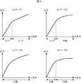
撮像素子1は非線形の入出力特性であるとしたが、図3に示す撮像素子の入出力特性を用いて詳細に説明する。
図3の(a)ケース1は、2種類のリニア特性を持ち、低輝度(入射光のレベルが低い)部分と比較して、高輝度部分の圧縮率を高くしている。高輝度(入射光のレベルが高い)部分を圧縮することで、画素飽和点をより高輝度側へシフトさせることができ、一般的なリニア特性の撮像素子に比べ、ワイドダイナミックレンジを実現可能である。さらに、後述のケース2〜4に対して、対数変換の演算量を削減できることから、低コスト化や小型化、低消費電力化を実現できる。The image pickup device 1 has nonlinear input / output characteristics, but will be described in detail using the input / output characteristics of the image pickup device shown in FIG.
The case 1 in FIG. 3 has two types of linear characteristics, and the compression ratio of the high luminance part is higher than that of the low luminance (incident light level is low) part. By compressing the high-brightness (incident light level is high) part, the pixel saturation point can be shifted to a higher-brightness side, and a wider dynamic range can be achieved compared to general linear imaging devices. is there. Furthermore, since the calculation amount of logarithmic conversion can be reduced with respect to
また図3の(b)ケース2は、低輝度部分はリニア特性であり、高輝度部分は対数特性とし、高輝度になればなるほど圧縮率を高くしている。これにより、ケース1に対してさらにワイドダイナミックレンジ化が可能である。さらに、後述するコントラスト拡大を、圧縮率が高い高輝度部分のみに適用する構成とすれば、演算量を削減できることから、低コスト化や小型化、低消費電力化が可能である。 In FIG. 3B,
また図3の(c)ケース3は全輝度領域で対数特性である。これにより、(b)ケース2に対してさらにワイドダイナミックレンジ化が可能である。
また図3の(d)ケース4は、2種類の対数特性を持ち、低輝度部分と比較して、高輝度部分の圧縮率を高くしている。これにより、(c)ケース3に対してさらにワイドダイナミックレンジ化が可能である。
また図3のケース1〜4は、本発明における撮像素子の入出力特性の一例であり、特定の輝度領域、あるいは全輝度領域について所定の関数により圧縮した非線形特性であれば、上記以外でもよい。Further, (c) Case 3 in FIG. 3 has logarithmic characteristics in the entire luminance region. As a result, (b) a wider dynamic range is possible with respect to
Further, (d) Case 4 in FIG. 3 has two types of logarithmic characteristics, and the compression ratio of the high luminance portion is higher than that of the low luminance portion. As a result, (c) a wider dynamic range is possible with respect to case 3.
Cases 1 to 4 in FIG. 3 are examples of the input / output characteristics of the image sensor according to the present invention, and may be other than the above as long as the nonlinear characteristics are compressed by a predetermined function for a specific luminance region or all luminance regions. .
図1の入力手段2について詳細を説明する。所定の処理とは、撮像素子からの信号を入力して、後段の信号処理を行うブロック(コントラスト拡張手段3、信号レベル検出手段4、コントラスト制御手段5)にて画像信号処理を行うための入力インタフェース処理であり、例えばA/D変換処理やLVDS(Low Voltage Differential Signaling)信号をデジタル信号に変換する処理であり、また例えば、撮像素子と信号処理部との処理タイミングを調整する同期調整処理である。尚、入力手段2は、レベル調整のためのゲインコントロールや、フィルタ処理等、所定の画像信号処理を含む構成であってもよい。 Details of the input means 2 of FIG. 1 will be described. The predetermined processing is an input for performing image signal processing in a block (contrast expansion means 3, signal level detection means 4, and contrast control means 5) that receives a signal from the image sensor and performs subsequent signal processing. Interface processing, for example, A / D conversion processing, processing for converting LVDS (Low Voltage Differential Signaling) signals into digital signals, and for example, synchronization adjustment processing for adjusting processing timing between the image sensor and the signal processing unit is there. The
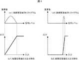
コントラスト拡張手段3、信号レベル検出手段4、コントラスト制御手段5について図4を用いて詳細を説明する。信号レベル検出手段4は、画像内の所定の画素領域における信号がどのようなものかを検出する。検出する数値は、例えばヒストグラム分布、最大値、最小値、平均値、周波数分布等、画像領域の信号分布を示す情報となる数値である。 The details of the contrast expansion means 3, the signal level detection means 4, and the contrast control means 5 will be described with reference to FIG. The signal level detection means 4 detects what kind of signal is in a predetermined pixel area in the image. The numerical value to be detected is a numerical value serving as information indicating the signal distribution of the image region, such as a histogram distribution, a maximum value, a minimum value, an average value, and a frequency distribution.
図4の(a1)と(a2)は、低輝度領域と高輝度領域を撮影した際の2つのケースについてのヒストグラム分布である。コントラスト制御手段5は、このヒストグラム分布情報と前記撮像素子1の入出力特性の情報を基に、コントラスト拡張手段3の折れ線補正の入出力特性を制御し、ヒストグラムを拡大する。例えば図4の(b1)と(b2)のようなヒストグラム拡大処理である。以上の演算によれば、画像領域ごとに、圧縮された信号を最大限に復元可能であり、ワイドダイナミックレンジを維持しつつ高コントラスト化を実現可能である。 (A1) and (a2) in FIG. 4 are histogram distributions for two cases when a low luminance region and a high luminance region are photographed. The contrast control means 5 controls the input / output characteristics of the polygonal line correction of the contrast expanding means 3 based on the histogram distribution information and the information on the input / output characteristics of the image sensor 1, and enlarges the histogram. For example, histogram enlargement processing such as (b1) and (b2) in FIG. According to the above calculation, the compressed signal can be restored to the maximum for each image area, and high contrast can be realized while maintaining a wide dynamic range.
尚、コントラスト拡張手段3は折れ線補正としたが、非線形の特性でもよく、例えばカーブ補正でもよい。
図5は、カーブ補正の場合のヒストグラム拡大処理を示す。この場合、ヒストグラム分布において、より画素数の多い箇所を中心にコントラスト拡大を行うことが可能である。The contrast expanding means 3 is a polygonal line correction, but it may have a non-linear characteristic, for example, a curve correction.
FIG. 5 shows a histogram enlargement process in the case of curve correction. In this case, in the histogram distribution, it is possible to perform contrast expansion centering on a portion having a larger number of pixels.
また、信号レベル検出手段4はヒストグラムを検出する代わりにより少ない演算量で検出可能な平均値、最大値と最小値、周波数分布等の少なくともひとつを検出し、コントラスト制御手段5は信号レベル検出手段4からの情報を基にヒストグラム分布を推定し、該推定したヒストグラム分布と前記撮像素子の入出力特性の情報に応じてコントラスト拡大手段3を制御する方法であってもよい。例えば、通常被写体を映した場合、そのヒストグラムの分布は平均値を中心として一定の輝度範囲に分布する確率が高い。さらに撮像素子が例えば対数圧縮等の入出力特性であった場合は、平均値が低輝度であればヒストグラム分布が広めであり、高輝度であればヒストグラム分布が狭い確率が高い。 Further, the signal level detection means 4 detects at least one of an average value, maximum value and minimum value, frequency distribution, etc. that can be detected with a smaller amount of computation instead of detecting the histogram, and the contrast control means 5 detects the signal level detection means 4. A method may be used in which the histogram distribution is estimated based on the information from, and the contrast enlarging means 3 is controlled in accordance with the estimated histogram distribution and information on the input / output characteristics of the image sensor. For example, when a normal subject is projected, there is a high probability that the distribution of the histogram is distributed in a certain luminance range centering on the average value. Furthermore, when the image sensor has input / output characteristics such as logarithmic compression, the histogram distribution is wide when the average value is low, and the probability that the histogram distribution is narrow is high when the average is high.
以上の原理から、例えば信号レベル検出手段4は平均値を検出するものとし、コントラスト制御手段5は撮像素子1の入出力特性を表す情報を保持しておき、前記信号レベル検出手段4からの平均値と前記撮像素子1の入出力特性の情報を基にヒストグラム分布を予測し、コントラスト拡張手段3の強弱を決定する。以上の構成であっても、前記信号レベル検出手段4がヒストグラム分布を検出する構成と同等の効果を得ることができ、且つ少ない演算量で実現できる。 Based on the above principle, for example, the signal level detection unit 4 detects an average value, and the
また、最大値と最小値はヒストグラム分布の最大値と最小値であるから、信号レベル検出手段4が最大値と最小値を検出する場合であったとしても、ヒストグラム分布の予測は可能であり、前記信号レベル検出手段4がヒストグラム分布を検出する構成と同等の効果を得ることができる。
また、DCT(離散コサイン変換)やFFT(高速フーリエ変換)、アダマール変換、特定の周波数レスポンスを抽出するバンドパスフィルタ等、少なくとも1種類以上の周波数の特性を把握できれば、周波数分布は信号レベルの振幅であることから最大値と最小値を特定できるため、ヒストグラム分布の予測は可能であり、前記信号レベル検出手段4がヒストグラム分布を検出する構成と同等の効果を得ることができる。In addition, since the maximum value and the minimum value are the maximum value and the minimum value of the histogram distribution, even if the signal level detection means 4 detects the maximum value and the minimum value, the histogram distribution can be predicted. An effect equivalent to the configuration in which the signal level detecting means 4 detects the histogram distribution can be obtained.
If the characteristics of at least one frequency, such as DCT (Discrete Cosine Transform), FFT (Fast Fourier Transform), Hadamard Transform, or a bandpass filter that extracts a specific frequency response, can be grasped, the frequency distribution will be the amplitude of the signal level. Therefore, since the maximum value and the minimum value can be specified, the histogram distribution can be predicted, and the same effect as the configuration in which the signal level detection means 4 detects the histogram distribution can be obtained.
尚、前記コントラスト制御手段5において撮像素子1の入出力特性を表す情報を保持するとしたが、入力レベルと出力レベルを対応付けた情報をテーブルとして保持する方法でよい。上記によれば、入出力特性の正確な把握が可能である。また、入出力特性を表す関数式を保持する方法でもよい。上記によれば、入出力特性の正確な把握が可能であり、且つテーブルとして保存しておく方法に比べて保持するデータ量を削減できる。 Although the contrast control means 5 holds information representing the input / output characteristics of the image sensor 1, a method of holding information associating the input level with the output level as a table may be used. Based on the above, it is possible to accurately grasp the input / output characteristics. Alternatively, a method of holding a function expression representing input / output characteristics may be used. According to the above, it is possible to accurately grasp the input / output characteristics, and it is possible to reduce the amount of data to be retained as compared with the method of storing as a table.
また、複数の入射光の輝度レベルにおける圧縮率情報など、入出力特性を推定できる情報を保持する方法でもよい。上記によれば、例えばデータを間引いた状態で保持しておき近似補間することで入出力特性の正確な把握が可能であり、且つテーブルとして保存しておく方法に比べて保持するデータ量を削減できる。また、関数式を保持する方法は関数が多項式になればなるほど演算量が増えるが、間引いた状態のデータを近似補間で実現すれば相対的に演算量を削減できる。 Alternatively, a method of holding information that can estimate input / output characteristics, such as compression rate information at the luminance levels of a plurality of incident lights, may be used. According to the above, for example, it is possible to accurately grasp the input / output characteristics by holding the data in a thinned state and performing approximate interpolation, and reducing the amount of data to be held compared to the method of saving as a table it can. Further, the method of holding the function formula increases the calculation amount as the function becomes a polynomial, but the calculation amount can be relatively reduced if the thinned data is realized by approximate interpolation.
出力手段6について詳細を説明する。所定の処理とは、TVやストレージ等の出力機器の信号フォーマットに変換する出力インタフェース処理であり、例えばNTSCやPALのビデオ出力に変換するものであり、例えばHDMI信号に変換するものであり、例えばネットワークのTCP/IPプロトコル信号に変換するものである。尚、出力手段6は、レベル調整のためのゲインコントロールや、フィルタ処理、エンコードによる圧縮処理等、所定の画像信号処理を含む構成であってもよい。
以上の構成により、ワイドダイナミックレンジを実現しつつ、且つ撮影した被写体に応じて最適なコントラスト感となる映像を生成する画像処理装置を実現できる。Details of the output means 6 will be described. The predetermined processing is output interface processing for converting to a signal format of an output device such as a TV or a storage, for example, converting to a video output of NTSC or PAL, for example, converting to an HDMI signal, for example, Converts to network TCP / IP protocol signals. The output means 6 may be configured to include predetermined image signal processing such as gain control for level adjustment, filter processing, and compression processing by encoding.
With the configuration described above, it is possible to realize an image processing apparatus that generates an image having an optimal contrast feeling according to a photographed subject while realizing a wide dynamic range.
本発明における実施例2について詳細に説明する。実施例2では、実施例1と同様に、被写体からの入射光を光電変換し画像信号として出力し且つその入出力特性が非線形である撮像素子1と、該撮像素子1からの画像信号に所定の処理を行い入力する入力手段2と、該入力手段2からの画像信号に対してコントラストの拡張を行うコントラスト拡張手段3と、前記入力手段2からの画像信号の信号レベルを検出する信号レベル検出手段4と、該信号レベル検出手段4からの信号と前記撮像素子1の入出力特性の情報を基に前記コントラスト拡張手段3におけるコントラスト拡張の強弱を制御するコントラスト制御手段5と、前記コントラスト拡張手段3からの画像信号を所定の処理を行い出力する出力手段6と、を持つ構成とした。 Example 2 in the present invention will be described in detail. In the second embodiment, as in the first embodiment, incident light from a subject is photoelectrically converted and output as an image signal, and the input / output characteristics thereof are nonlinear, and the image signal from the image sensor 1 is predetermined. The input means 2 for performing the above processing, the contrast expanding means 3 for expanding the contrast of the image signal from the input means 2, and the signal level detection for detecting the signal level of the image signal from the input means 2 Means 4, contrast control means 5 for controlling the strength of contrast expansion in the contrast expansion means 3 based on the signal from the signal level detection means 4 and information on the input / output characteristics of the image sensor 1, and the contrast expansion means And an output means 6 for outputting the image signal from 3 by performing a predetermined process.
またさらに実施例2においては、前記撮像素子1を各画素上に複数のカラーフィルタを備えたカラー単板撮像素子とし、コントラスト補正手段3はカラーマトリクス演算とした。
例えばカラーフィルタがRGBであるRGBベイヤ配列の撮像素子であり、かつ対数型の入出力特性を持つ場合を説明する。Furthermore, in Example 2, the image pickup device 1 is a color single-plate image pickup device having a plurality of color filters on each pixel, and the contrast correction means 3 is a color matrix operation.
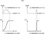
For example, a case where the color filter is an RGB Bayer array image sensor with RGB and has logarithmic input / output characteristics will be described.
図6の分光特性が表すようにこの場合は、低輝度領域を撮影した際の各画素の分光特性(a)と、高輝度領域を撮影した際の各画素の分光特性(b)が異なる。特に分光特性(b)は、各色が混色しているため、そのまま画像化すると色のコントラストが低い画像となる。即ち、入出力特性が非線形であるカラー撮像素子を用いた場合、入射光の輝度レベルに応じて色再現が変化してしまうという課題があった。 As shown by the spectral characteristics of FIG. 6, in this case, the spectral characteristics (a) of each pixel when a low-luminance area is imaged differ from the spectral characteristics (b) of each pixel when a high-luminance area is imaged. In particular, the spectral characteristic (b) is a mixture of colors, so that when the image is formed as it is, an image with low color contrast is obtained. That is, when a color image sensor having non-linear input / output characteristics is used, there is a problem that color reproduction changes according to the luminance level of incident light.
そこで本発明では、コントラスト拡張手段3はカラーマトリクス演算を行うものとし、たとえば(式1)で示すマトリクス演算を行うものとする。R_in、G_in、B_inはそれぞれ入力手段2からの信号であり、R_out、G_out、B_outはそれぞれコントラスト拡張手段3の出力信号である。また、K**はマトリクス係数である。 Therefore, in the present invention, the contrast expanding means 3 performs color matrix calculation, for example, matrix calculation represented by (Equation 1). R_in, G_in, and B_in are signals from the
R_out = R_in×Krr + G_in×Kgr + B_in×Kbr
G_out = R_in×Krg + G_in×Kgg + B_in×Kbg
B_out = R_in×Krb + G_in×Kgb + B_in×Kbb 以上(式1)R_out = R_in x Krr + G_in x Kgr + B_in x Kbr
G_out = R_in x Krg + G_in x Kgg + B_in x Kbg
B_out = R_in x Krb + G_in x Kgb + B_in x Kbb or more (Formula 1)
コントラスト制御手段5は、信号レベル検出手段3からの信号と前記撮像素子1の入出力特性の情報を基にマトリスク演算係数K**を制御するものとする。撮像素子1の入出力特性を表す情報は、実施例1と同様入出力特性をデータテーブルとして保持する方法でよく、また入出力特性を表す関数式を保持する方法でもよい。また、複数の入射光の輝度レベルにおける圧縮率情報など、入出力特性を推定できる情報を保持する方法でもよい。また、色信号毎に個別に入出力特性を表す情報、あるいは推定できる情報を保持する方法でもよい。また、入射光の輝度レベルに応じて変化する分光特性情報を保持する方法でもよい。制御方法は、例えば高輝度領域の分光特性において混色が多い場合、混色を除去するよう係数を制御するものとする。
以上の構成によれば、画像領域ごとに、圧縮された色信号を最大限に復元可能であり、ワイドダイナミックレンジを維持しつつ、且つ撮影した被写体に応じて最適な色コントラスト感のとなる映像を生成する画像処理装置を実現できる。The contrast control means 5 controls the mat risk calculation coefficient K ** based on the signal from the signal level detection means 3 and the information on the input / output characteristics of the image sensor 1. The information indicating the input / output characteristics of the image sensor 1 may be a method of holding the input / output characteristics as a data table as in the first embodiment, or may be a method of holding a function expression indicating the input / output characteristics. Alternatively, a method of holding information that can estimate input / output characteristics, such as compression rate information at the luminance levels of a plurality of incident lights, may be used. Alternatively, a method of holding information representing input / output characteristics individually for each color signal or information that can be estimated may be used. Alternatively, a method of holding spectral characteristic information that changes according to the luminance level of incident light may be used. In the control method, for example, when there are many mixed colors in the spectral characteristics of the high luminance region, the coefficient is controlled so as to remove the mixed colors.
According to the above configuration, a compressed color signal can be restored to the maximum for each image area, and a video having an optimal color contrast feeling according to the photographed subject while maintaining a wide dynamic range. Can be realized.
本発明における実施例3について詳細に説明する。
図2は、本発明の実施例3における画像情報処理装置の基本構成図である。被写体からの入射光を光電変換し画像信号として出力する際、少なくとも2つ以上の感度特性の異なる画像信号を出力する撮像素子1と、該撮像素子1からの各画像信号に対して所定の処理を行い入力する入力手段2と、該入力手段2からの画像信号に対してコントラストの拡張を行うコントラスト拡張手段3a,3bと、前記入力手段からの画像信号の信号レベルを検出する信号レベル検出手段4a,4bと、該信号レベル検出手段からの信号と前記撮像素子の入出力特性の情報を基に前記コントラスト拡張手段3a,3bにおけるコントラスト拡張の強弱を制御するコントラスト制御手段5a,5bとを個別に有し、前記コントラスト拡張手段3a,3bからの各画像信号をひとつの画像信号に合成する合成手段7と、該合成手段7からの画像信号を所定の処理を行い出力する出力手段6とを持つ構成とした。Example 3 in the present invention will be described in detail.
FIG. 2 is a basic configuration diagram of the image information processing apparatus according to the third embodiment of the present invention. When the incident light from the subject is photoelectrically converted and output as an image signal, at least two image signals having different sensitivity characteristics are output, and predetermined processing is performed on each image signal from the image sensor 1 Input means 2 for inputting,
撮像素子1は少なくとも2つ以上の感度特性の異なる画像信号を出力するとしたが、図2の構成図は、第1の信号と第2の信号という二つの画像信号を出力する場合の例である。第1の信号、第2の信号は例えば、図3の(b)ケース2におけるリニア特性の部分の画像信号と、対数特性の部分の画像信号である。
入力手段2には、前記撮像素子からの第1の信号と第2の信号が入力され、各々に対して前記実施例1または2に記載のものと同様の処理を行うものである。The image sensor 1 outputs at least two image signals having different sensitivity characteristics, but the configuration diagram of FIG. 2 is an example in the case of outputting two image signals of a first signal and a second signal. . The first signal and the second signal are, for example, an image signal having a linear characteristic and an image signal having a logarithmic characteristic in
The input means 2 receives the first signal and the second signal from the image sensor, and performs the same processing as that described in the first or second embodiment for each.
コントラスト拡張手段3a、信号レベル検出手段4a、コントラスト制御手段5aは前記入力手段2からの第1の信号に対して、前記実施例1に記載のものと同様の処理を行うものとし、コントラスト拡張手段3b、信号レベル検出手段4b、コントラスト制御手段5bは前記入力手段2からの第2の信号に対して、前記実施例1または2に記載のものと同様の処理を行うものとする。
以上の構成により、ワイドダイナミックレンジを実現しつつ、且つ撮影した被写体に応じて最適なコントラスト感となる映像を生成する画像処理装置を実現できる。The contrast expanding means 3a, the signal level detecting means 4a, and the contrast control means 5a perform the same processing as that described in the first embodiment on the first signal from the input means 2, and the contrast expanding means 3b, the signal level detection means 4b, and the contrast control means 5b perform the same processing as that described in the first or second embodiment on the second signal from the input means 2.
With the configuration described above, it is possible to realize an image processing apparatus that generates an image having an optimal contrast feeling according to a photographed subject while realizing a wide dynamic range.
また、第1の信号と第2の信号に対して個別に信号レベルを検出することができるため、第1の信号と第2の信号が合成された信号に対して信号レベルを検出する実施例1の構成に比べて、より高精度な検出が可能である。また、第1の信号と第2の信号に対して個別にコントラスト制御を行うため、第1の信号と第2の信号が合成された信号に対してコントラスト制御を行う実施例1または2の構成に比べて、より高精度な制御が可能である。また、第1の信号と第2の信号に対して個別にコントラスト拡張を行った後に合成するため、第1の信号と第2の信号が合成された信号に対してコントラスト拡張を行う実施例1または2の構成に比べて、より高精度なコントラスト拡張が可能である。 In addition, since the signal level can be individually detected for the first signal and the second signal, the signal level is detected for the signal obtained by combining the first signal and the second signal. Compared with the configuration of 1, the detection can be performed with higher accuracy. In addition, since contrast control is individually performed on the first signal and the second signal, the configuration of the first or second embodiment in which contrast control is performed on a signal obtained by combining the first signal and the second signal. Compared to the above, more accurate control is possible. In addition, in order to combine the first signal and the second signal after individually expanding the contrast, the first embodiment performs the contrast expansion on the signal obtained by combining the first signal and the second signal. Alternatively, the contrast can be expanded with higher accuracy than in the second configuration.
さらには、第1の信号と第2の信号を個別にコントラスト拡張後に合成するため、第1の信号と第2の信号が合成された信号に対してコントラスト拡張を行う実施例1または2の構成に比べて、各々少ないビット精度での演算にて同等の演算精度を維持できる。例えば、実施例1または2の構成における入力手段2の出力ビット精度が32bit精度であった場合、本実施例3の構成で同等の演算精度とするためには、第1の信号と第2の信号は各々16bitとし、合成手段による合成後32bitとすればよい。通常、bit数が少ない方がオーバーヘッドは小さいため、回路で実現する場合は回路規模を縮小でき、ソフトウェアで実現する場合は演算時間を短縮できる。 Furthermore, since the first signal and the second signal are individually combined after the contrast expansion, the configuration of the first or second embodiment in which the contrast expansion is performed on the signal obtained by combining the first signal and the second signal. Compared to the above, it is possible to maintain the same calculation accuracy with less bit accuracy. For example, when the output bit accuracy of the input means 2 in the configuration of the first or second embodiment is 32 bit accuracy, in order to obtain the same calculation accuracy in the configuration of the third embodiment, the first signal and the second signal Each signal may be 16 bits and 32 bits after combining by the combining means. Usually, the smaller the number of bits, the smaller the overhead, so the circuit scale can be reduced when implemented with a circuit, and the computation time can be shortened when implemented with software.
本発明における実施例4について詳細に説明する。本実施例4では、前記実施例1〜3のいずれかの構成であって、前記入出力特性が非線形である撮像素子1において、所定の入射光(輝度)レベルで特性が変化する特性変化点を持つ撮像素子とした。例えば、図3の(a)(b)(d)のような特性変化点を持つ撮像素子である。 Example 4 in the present invention will be described in detail. In the fourth embodiment, the characteristic change point at which the characteristic changes at a predetermined incident light (luminance) level in the imaging device 1 having the non-linear input / output characteristic according to any one of the first to third embodiments. It was set as the image pick-up element having. For example, it is an image sensor having characteristic change points as shown in FIGS.
該特性変化点を持つ撮像素子は、例えば光電変換した電荷を特性変化点前の電荷と特性変化点後の電荷分に分けてキャパシタに格納しておき、合成して出力あるいは個別に出力することで実現できる。しかしながら、キャパシタに格納する際の電荷損失等により、合成後の特性変化点付近で出力レベルが下がってしまうという問題がある。
図7は、この場合の入出力特性の一例を示す。上記特性変化点付近でレベルが下がると、画像ではノイズとして現れる。The image sensor having the characteristic change point, for example, separates the photoelectrically converted charge into the charge before the characteristic change point and the charge after the characteristic change point, stores them in the capacitor, and synthesizes and outputs them or outputs them individually. Can be realized. However, there is a problem that the output level decreases near the characteristic change point after synthesis due to charge loss or the like when stored in the capacitor.
FIG. 7 shows an example of input / output characteristics in this case. When the level decreases near the characteristic change point, it appears as noise in the image.
そこで、本発明における実施例4では、前記コントラスト制御手段5は撮像素子1の入出力特性の情報として特性変化点の情報を保持し、該特性変化点の情報と前記信号レベル検出手段4からの情報を基に、特性変化点付近のノイズ成分を増幅しないよう前記コントラスト拡張手段3を制御する構成とした。ここでノイズ成分を増幅しない制御とは、例えば特性変化点付近のコントラスト拡大を弱める、あるいは特性変化点付近のコントラスト拡大がかからないようにする、あるいは特性変化点付近のコントラストを拡大せず縮小させることで実現できる。
以上の構成により、ワイドダイナミックレンジを実現しつつ、特性変化点付近のノイズを増幅することなく、且つ撮影した被写体に応じて最適なコントラスト感となる映像を生成する画像処理装置を実現できる。Therefore, in Embodiment 4 of the present invention, the contrast control means 5 holds information on characteristic change points as information on the input / output characteristics of the image sensor 1, and the information on the characteristic change points and the signal level detection means 4 Based on the information, the contrast extending means 3 is controlled so as not to amplify the noise component near the characteristic change point. Here, the control that does not amplify the noise component means, for example, that the contrast expansion near the characteristic change point is weakened, the contrast expansion near the characteristic change point is not applied, or the contrast near the characteristic change point is reduced without being enlarged. Can be realized.
With the above configuration, it is possible to realize an image processing apparatus that generates a video with an optimal contrast feeling according to a photographed subject without amplifying noise near the characteristic change point while realizing a wide dynamic range.
本発明における実施例5について詳細に説明する。本実施形態では、撮像装置の一例であるビデオカメラにおいて、被写体を撮影する例を用いて説明する。本実施形態は、たとえば屋外での撮影や、極めて明るい被写体が一部に映り込むようなコントラストの高いシーンにおいて、特に有効である。 A fifth embodiment of the present invention will be described in detail. In this embodiment, a video camera that is an example of an imaging apparatus will be described using an example of photographing a subject. This embodiment is particularly effective in, for example, outdoor shooting or a high-contrast scene in which a very bright subject is partly reflected.
図8は、実施例5におけるビデオカメラ(画像情報処理装置)の基本構成図である。本実施例は撮像素子1、入力手段2、コントラスト拡張手段3、信号レベル検出手段4、コントラスト制御手段5、出力手段6、レンズ部8、制御部9を有する。また、入力手段2はAFE部21、駆動部22、センサデータ処理部23を有する。また、出力手段6は輝度処理部61、色差処理部62、ズーム手段63、エンコード手段64を有する。以下、各構成要素の動作について、順に説明する。 FIG. 8 is a basic configuration diagram of a video camera (image information processing apparatus) according to the fifth embodiment. The present embodiment includes an imaging device 1, an
まず、被写体から発せられた光線はレンズ部8に入射する。レンズ部8は図示されていない光学ズーム及びメカアイリスなどの機構を有し、これらは後述の通り制御部9によって制御される。レンズ部8では、メカアイリスによる光量調整が行われ、ズームレンズによってズームが施された後、撮像素子1上に被写体の像が結ばれる。 First, the light beam emitted from the subject enters the
撮像素子1では結ばれた像の明るさに応じて画素ごとに光電変換が行われ、各画素位置に対応したアナログ信号に変換されて入力手段2へ出力される。
撮像素子1は入出力特性の異なる2つ以上の映像信号を同時に出力できるという特徴を有する。撮像素子1の例を図9に示す。
図9は、2×2のベイヤ配列を有する撮像素子を示すが、R画素、G画素、B画素に加えて対数的な入出力特性を有する画素(本実施例ではL画素と呼ぶ)を持つことにより、リニアな入出力特性の映像信号(R画素、G画素、B画素)と対数的な入出力特性(L画素)を同時に出力することができる。
図10は、図9の撮像素子における入出力特性の例を示す。リニアな特性を持つ画素では一定以上の明るさになると出力が飽和してしまうが(図中の3000)、対数的な特性を持つL画素の出力は高輝度部分が圧縮されているため、飽和せずに階調を表現することができる(図中の3010)。また、撮像素子1は、リニア画素(RGBの各画素)と対数画素(L画素)のシャッタスピードを独自に制御可能な構成になっている。In the image sensor 1, photoelectric conversion is performed for each pixel according to the brightness of the connected image, converted into an analog signal corresponding to each pixel position, and output to the
The image sensor 1 has a feature that it can simultaneously output two or more video signals having different input / output characteristics. An example of the image sensor 1 is shown in FIG.
FIG. 9 shows an image sensor having a 2 × 2 Bayer array, but has pixels having logarithmic input / output characteristics (referred to as L pixels in this embodiment) in addition to R pixels, G pixels, and B pixels. As a result, a video signal (R pixel, G pixel, B pixel) having a linear input / output characteristic and a logarithmic input / output characteristic (L pixel) can be output simultaneously.
FIG. 10 shows an example of input / output characteristics in the image sensor of FIG. For pixels with linear characteristics, the output saturates when the brightness exceeds a certain level (3000 in the figure), but the output of L pixels with logarithmic characteristics is saturated because the high-intensity part is compressed. The gradation can be expressed without (3010 in the figure). Further, the image sensor 1 has a configuration capable of independently controlling the shutter speeds of linear pixels (RGB pixels) and logarithmic pixels (L pixels).
撮像素子1の駆動は駆動部22により行われる。駆動部22には、後述する制御部9からリニア画素用のシャッタ制御信号と対数画素用のシャッタ制御信号が入力される。駆動手段22はこれらを用いてリニア画素用の駆動信号と対数画素用の駆動信号を生成し、撮像素子1に供給してシャッタ制御を行う。
以上の構成により、撮像素子1ではリニア特性の映像信号と対数特性の映像信号を同時に撮像することが可能であり、これらを用いて高画質、高性能の制御を実現することができる。詳細については後述する。The image pickup device 1 is driven by the
With the above-described configuration, the image sensor 1 can simultaneously capture a linear characteristic video signal and a logarithmic characteristic video signal, and by using these, high image quality and high performance control can be realized. Details will be described later.
入力手段2へ入力された各映像信号は、AFE部21へ入力される。AFE部21では相関二重サンプリングによるノイズ除去処理、増幅器による信号増幅処理、A/D変換処理などが施され、デジタル信号に変換された後、センサデータ処理部23へ出力される。
センサデータ処理部23では、センサの傷により欠損したデータの補正、ランダムノイズ除去、固定パターンノイズ除去などのデータ処理が施され、コントラスト拡張手段3および信号レベル検出手段4へ出力される。信号レベル検出手段4での処理は後述する。Each video signal input to the input means 2 is input to the
The sensor
コントラスト拡張手段3の動作は本発明の第1の実施例および第2の実施例においてにおいて詳細に説明されているため、本実施例では説明を割愛する。
コントラスト拡張手段3より出力された映像信号は、出力手段6に入力される。出力手段6では、入力された信号に各信号処理を施し、最終的な映像信号に変換して出力する。まず、入力された信号は輝度処理部61および色差処理部62に入力され、輝度処理部61においては輝度信号の生成、ノイズ除去やエンハンサなどの各種フィルタ処理、ガンマ補正などが施された後、ズーム手段63へ出力される。また、色差処理部62においては色差信号の生成、ノイズ除去などの各種フィルタ処理、ガンマ補正、色補正などが施された後、ズーム手段63へ出力される。Since the operation of the contrast expanding means 3 has been described in detail in the first and second embodiments of the present invention, description thereof will be omitted in this embodiment.
The video signal output from the contrast expansion unit 3 is input to the
ズーム手段63では輝度信号及び色差信号のタイミング合わせを行い、リニア特性の映像信号と対数特性の映像信号の合成などが行われる。また、必要に応じて電子ズーム処理が施された後、エンコード手段64へ出力される。
エンコード手段64では、TVやストレージ等の出力機器の信号フォーマットに変換する出力インタフェース処理が施される。具体的には、例えばNTSCやPALのビデオ出力に変換するものであり、例えばHDMI信号に変換するものであり、例えばネットワークのTCP/IPプロトコル信号に変換するものである。In the zoom means 63, the timing of the luminance signal and the color difference signal is adjusted, and the linear characteristic video signal and the logarithmic characteristic video signal are combined. Further, after being subjected to electronic zoom processing as necessary, it is output to the encoding means 64.
The encoding means 64 performs an output interface process for converting into a signal format of an output device such as a TV or a storage. Specifically, for example, it converts to a video output of NTSC or PAL, for example, converts to an HDMI signal, for example, converts to a TCP / IP protocol signal of a network.
信号レベル検出手段4では、コントラスト拡張手段3より出力された映像信号をもとに、画像内の所定の画素領域における信号がどのようなものかを検出する。検出する数値は、例えばヒストグラム分布、最大値最小値、平均値、周波数分布等、画像領域の信号分布を示す情報となる数値である。例示した信号の中には、AF(オートフォーカス)制御で使用する合焦信号も含まれる。信号レベル検出手段4から出力される検出信号は、例示したいずれか1つが出力されても、例示された以外の検出信号が出力されても、あるいは複数種類の検出信号が並列に出力されてもよいものとする。詳細は実施例1において記載されているので、本実施例では説明を割愛する。信号レベル検出手段4からの出力は制御部9に入力される。 The signal level detection unit 4 detects what kind of signal is in a predetermined pixel area in the image based on the video signal output from the contrast expansion unit 3. The numerical value to be detected is a numerical value serving as information indicating the signal distribution of the image region, such as a histogram distribution, maximum value minimum value, average value, frequency distribution, and the like. The exemplified signals include a focusing signal used in AF (autofocus) control. The detection signal output from the signal level detection means 4 may be output as any one of the exemplified signals, a detection signal other than those illustrated, or a plurality of types of detection signals may be output in parallel. Be good. Since details are described in the first embodiment, the description is omitted in this embodiment. The output from the signal level detection means 4 is input to the
制御部9はたとえばコントラスト制御手段5に代表される各種の制御手段を有し、信号レベル検出手段4からの検出信号やレンズ部からのF値指示信号など元に、カメラを構成する各部の動作を制御する。たとえば、コントラスト制御手段5は、信号レベル検出手段4からの検出信号を元に、コントラスト拡張手段3の動作を制御する。制御方法の詳細については、実施例1及び実施例2に詳細に記載されているため、本実施例では説明を割愛する。同様の手法により、制御部9からはレンズ部8を制御するアイリス制御信号や光学ズーム倍率制御信号、駆動部22を制御するシャッタ制御信号、出力手段6を制御する画質パラメータ制御信号などが出力され、本実施例のビデオカメラを構成する各部の動作制御が行われる。 The
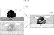
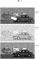
図11は、本実施例の撮像素子1で撮影した映像の第1の例を示す。リニア特性の映像信号はたとえば画像4000のようになり、屋外での撮影では空などの明るい部分は白飛びし、影などの暗い部分は黒つぶれしてしまう。一方、対数特性の映像信号はたとえば画像4010のようになり、どの明るさにおいても階調は維持されているが、コントラスト感に乏しい画像となる。これらの特徴を生かし、画像処理を最適化して例えば画像4020のように階調とコントラスト感が両立させることができる。以下、いくつか例を示す。 FIG. 11 shows a first example of an image captured by the image sensor 1 of the present embodiment. An image signal having a linear characteristic is, for example, an
AE制御への応用について述べる。リニア特性と対数特性の映像が同時に撮影でき、露光をそれぞれについて制御できるものとすると、リニア特性の映像はある程度の白飛びや黒つぶれを許容して露光制御を行えばよい。
図12は、撮像素子1で撮影した映像のヒストグラムの例を示す。
たとえば、前記の映像4000について輝度のヒストグラムをとると、図12の5000のようになり、高輝度部分と低輝度部分の度数が高く、中間階調の度数が低くなる。この場合、通常のAE制御では注目する部分に合わせて(明るい部分に着目するなら黒つぶれを許容して明るい部分の階調を出すように)露光制御を行うことになる。しかしながら、本実施例においては、中間階調をきっちり出し、白飛びおよび黒つぶれを許容するように露光を制御すればよい。Application to AE control will be described. Assuming that images with linear characteristics and logarithmic characteristics can be taken at the same time, and exposure can be controlled for each, exposure control can be performed with a certain degree of whiteout and blackout allowed.
FIG. 12 shows an example of a histogram of an image shot with the image sensor 1.
For example, when the luminance histogram is taken for the
他方、対数特性の映像はヒストグラムのピークが中間輝度に来るように露光制御を行えばよい。たとえば、前記の映像4010について輝度のヒストグラムをとると、図12の5010のようになり、広がりの少ない分布となる。この場合、対数特性の映像については、ヒストグラムのピークがちょうど中間輝度に来るように露光制御を行うことにより、明るい側、暗い側とも階調を損なわずに撮像することができる。このようにして撮影した2枚の映像について、前述の方法でコントラストの拡張を行い、合成することにより、非常にコントラストの高い映像を得ることが可能である。 On the other hand, exposure control may be performed so that the logarithmic characteristic image has a histogram peak at an intermediate luminance. For example, when a histogram of luminance is taken for the
次いで、AF制御について述べる。リニア制御の画像においては、しばしばフォーカス制御が困難な場合がある。たとえば、暗い中に点光源が存在するような場合、点光源周辺が飽和してしまうと、その飽和部分を物体と誤認識して実際の物体にフォーカスが合わない状況が発生する。
図13は、本実施例の撮像素子1で撮影した映像の第2の例を示す。映像6000は、点光源(この場合は街灯部分)およびその周辺が飽和してしまい、ボケ止まりが発生している映像である。
図14は、フォーカス位置と合焦信号の関係の例を示す。図中の(a)がリニア制御の画像を元に生成した合焦信号である。一般的なAF制御では、合焦信号のレベルのピークが検出される位置にズームレンズを移動させるように制御される(山登り制御)。(a)から読み取れるとおり、本来の合焦ポイントのほかに、信号レベル検出手段4が(より具体的には該検出手段に含まれる合焦信号生成用のハイパスフィルタが)飽和した領域のエッジ部分を物体のエッジと誤認識してしまうために発生するピークが存在する。山登り制御によって飽和に起因するピーク検出位置にズームレンズを制御してしまうことがボケ止まりの原因である。Next, AF control will be described. Focus control is often difficult in linearly controlled images. For example, in the case where a point light source exists in the dark, if the periphery of the point light source is saturated, a situation occurs in which the saturated portion is erroneously recognized as an object and the actual object cannot be focused.
FIG. 13 shows a second example of an image captured by the image sensor 1 of the present embodiment. The
FIG. 14 shows an example of the relationship between the focus position and the focus signal. (A) in the figure is a focus signal generated based on a linear control image. In general AF control, control is performed such that the zoom lens is moved to a position where the peak of the level of the focus signal is detected (mountain climbing control). As can be seen from (a), in addition to the original in-focus point, the edge portion of the region where the signal level detecting means 4 (more specifically, the high-pass filter for generating the in-focus signal included in the detecting means) is saturated There is a peak that occurs due to misrecognizing as an edge of an object. Control of the zoom lens at the peak detection position caused by saturation by hill-climbing control is a cause of blurring.
しかしながらこの場合、同一シーンの対数特性の画像は、図13の映像6010のようになり、街灯部分は飽和していない。図14の(b)は対数特性の画像を元に生成した合焦信号であるが、飽和点が存在しないため、正しい合焦位置にのみピークが発生している。このため、映像6010を用いてAF制御を行うことにより、飽和による悪影響は受けずにフォーカスを合わせることが可能となる。 However, in this case, the logarithmic characteristic image of the same scene looks like the
あるいは、対数特性の合焦信号(b)をもとに粗くフォーカス位置の調整を行い、リニア特性の合焦信号(a)をもとにフォーカス位置の微調整を行ってフォーカス位置を決定しても良い。
上記のようなAE制御やAF制御はリアルタイム制御である必要があり、同一フレームでリニア特性の映像と線形特性の映像が同時に撮影できることがハンチングや誤動作を防ぐ上で大きなアドバンテージとなる。Alternatively, the focus position is coarsely adjusted based on the logarithmic characteristic focus signal (b), and the focus position is finely adjusted based on the linear characteristic focus signal (a) to determine the focus position. Also good.
The AE control and AF control as described above need to be real-time control, and it is a great advantage in preventing hunting and malfunctioning that a linear characteristic image and a linear characteristic image can be simultaneously captured in the same frame.
画質制御について説明する。図8の入力手段2の中には、たとえばセンサデータ処理部23が存在し、生のセンサデータに対して傷補正やノイズ除去処理が施される。リニア特性の映像と対数特性の映像のそれぞれに別々の強度でノイズ除去を施すことにより、最適な映像を得ることができる。たとえば、リニア特性の映像に黒つぶれが発生しており、これがコントラスト拡張によって拡大されるような場合には、連動してリニア特性の暗部ノイズを抑えるようにノイズ除去の強度を高めることにより、高画質を得ることができる。 The image quality control will be described. In the
さらに、明るい被写体を撮影した場合に、リニア特性の映像は飽和して白飛びし、対数特性の映像は飽和しないことがある。このような場合、たとえば対数特性の映像からリニア特性の映像を予測して飽和以上の値を表現することが可能となる。先の図10を用いて説明すると、リニアな入出力特性を持つ画素においては、特性3000のように、ある明るさ以上で出力が飽和してしまう。しかしながら、対数特性を持つ画素の入力特性は3010のようになり、リニア画素が飽和してしまっても対数画素は飽和しない。したがって、対数画素の入出力特性とリニア画素の入出力特性を対応付けしておくことにより、飽和以上の特性を類推することが可能となる。 Further, when a bright subject is photographed, the linear characteristic image may be saturated and whiteout, and the logarithmic characteristic image may not be saturated. In such a case, for example, it is possible to predict a linear characteristic image from a logarithmic characteristic image and express a value equal to or higher than saturation. Describing with reference to FIG. 10 described above, in a pixel having a linear input / output characteristic, the output is saturated at a certain brightness or more like the characteristic 3000. However, the input characteristic of a pixel having a logarithmic characteristic is 3010, and even if the linear pixel is saturated, the logarithmic pixel is not saturated. Therefore, by associating the input / output characteristics of the logarithmic pixel with the input / output characteristics of the linear pixel, it is possible to analogize characteristics exceeding saturation.
図15は、コントラスト拡張手段3の構成の例を示す。コントラスト拡張手段3は、コントラスト拡張部31、飽和判定部32、ROMデータ33、セレクタ34を有する。コントラスト拡張手段3にはリニア特性の画像信号と対数特性の映像信号が入力され、それぞれについてコントラスト拡張が行われる。コントラスト拡張の詳細については、実施例1および2に記載されており、ここでは詳細は割愛する。コントラスト拡張されたリニア特性の画像信号は飽和判定部32に入力され、飽和しているかどうかが判定される。一方、対数特性の画像信号はROMデータ33に入力される。ROMデータ33は、同一の明るさにおける対数特性の出力とリニア特性の出力を対応付けたデータであり、入力された対数特性の映像信号を元に、リニア特性の映像信号を出力する。リニア特性の映像信号とROMデータ33の出力信号はセレクタ34に入力され、飽和判定部32において飽和と判定された場合にはROMデータ33の出力を映出力し、飽和でないと判定された場合にはリニア特性の映像信号をそのまま出力する。このようにして、ダイナミックレンジの狭いリニア特性のデータに対しても、飽和レベル以上の階調を表現することができる。
対数データと線形データの対応付けは例示したようなテーブル形式でもよいし、関数あるいは多項式の形で対応付けしてもよい。以上の方式で飽和以上を補うことにより、輝度や色度のダイナミックレンジを広げることが可能となり、高画質化を図ることができる。FIG. 15 shows an example of the configuration of the contrast expanding means 3. The contrast extending unit 3 includes a
Correspondence between logarithmic data and linear data may be in the form of a table as illustrated, or may be associated in the form of a function or a polynomial. By compensating for saturation or more with the above method, the dynamic range of luminance and chromaticity can be expanded, and high image quality can be achieved.
なお、本発明は上記の実施例1〜5に限定されるものではなく、様々な変形例が含まれる。例えば、上記した実施例は本発明を分かりやすく説明するために詳細に説明したものであり、必ずしも説明した全ての構成を備えるものに限定されるものではない。また、ある実施例の構成の一部を他の実施例の構成に置換えることが可能であり、また、ある実施例の構成に他の実施例の構成を加えることも可能である。また、各実施例の構成の一部について、他の構成の追加・削除・置換えをすることが可能である。
また、上記の各構成は、それらの一部又は全部が、ハードウェアで構成されても、プロセッサでプログラムが実行されることにより実現されるように構成されてもよい。また、制御線や情報線は説明上必要と考えられるものを示しており、必ずしも実際の装置における全ての制御線や情報線を示しているとは限らない。実際には殆ど全ての構成が相互に接続されていると考えてもよい。In addition, this invention is not limited to said Examples 1-5, Various modifications are included. For example, the above-described embodiments have been described in detail for easy understanding of the present invention, and are not necessarily limited to those having all the configurations described. Further, a part of the configuration of one embodiment can be replaced with the configuration of another embodiment, and the configuration of another embodiment can be added to the configuration of one embodiment. In addition, it is possible to add, delete, and replace other configurations for a part of the configuration of each embodiment.
In addition, each of the above-described configurations may be configured such that some or all of them are configured by hardware, or are implemented by executing a program by a processor. In addition, the control lines and the information lines indicate what is considered necessary for the explanation, and do not necessarily indicate all the control lines and information lines in the actual apparatus. Actually, it may be considered that almost all the components are connected to each other.
1:撮像素子、2:入力手段、3:コントラスト拡張手段、4:信号レベル検出手段、5:コントラスト制御手段、6:出力手段、7:合成手段、8:レンズ部、9:制御部。 DESCRIPTION OF SYMBOLS 1: Image pick-up element, 2: Input means, 3: Contrast expansion means, 4: Signal level detection means, 5: Contrast control means, 6: Output means, 7: Synthesis | combination means, 8: Lens part, 9: Control part.
Claims (6)
Translated fromJapanese前記被写体から供給された入射光を光電変換して電気信号に変換し、前記入射光との間の入出力特性が非線形であって互いに異なる少なくも二つの特性を含む前記電気信号を出力する撮像素子と、
該撮像素子が出力した前記電気信号が供給され前記電気信号の信号レベルを検出する信号レベル検出手段と、
前記撮像素子が出力した前記電気信号が供給され前記電気信号に対する信号処理を行う信号処理手段と、
該信号処理手段で信号処理して得た前記画像信号を出力する出力手段と、
前記信号レベル検出手段から供給された前記検出信号と前記撮像素子の入出力特性の情報を基に前記信号処理手段を制御する制御手段を有し、
前記制御手段は、前記電気信号に対して前記検出信号に基づき少なくも二つの互いに特性の異なる露光制御を行うことを特徴とする画像信号処理装置。An image signal processing apparatus that images a subject and outputs an image signal related to the subject,
Imaging that photoelectrically converts incident light supplied from the subject and converts it into an electrical signal, and outputs the electrical signal including at least two different characteristics that are nonlinear in input / output characteristics with respect to the incident light Elements,
Signal level detection means for detecting the signal level of the electrical signal supplied with the electrical signal output from the imaging device;
Signal processing means for supplying the electrical signal output from the image sensor and performing signal processing on the electrical signal;
Output means for outputting the image signal obtained by signal processing by the signal processing means;
Control means for controlling the signal processing means based on the detection signal supplied from the signal level detection means and information on input / output characteristics of the image sensor;
The image signal processing apparatus, wherein the control means performs at least two exposure controls having different characteristics from each other on the electrical signal based on the detection signal.
前記被写体から供給された入射光を光電変換して電気信号に変換し、前記入射光との間の入出力特性が非線形であって互いに異なる少なくも二つの特性を含む前記電気信号を出力する撮像素子と、
該撮像素子が出力した前記電気信号が供給され前記電気信号の信号レベルを検出する信号レベル検出手段と、
前記撮像素子が出力した前記電気信号が供給され前記電気信号に対する信号処理を行う信号処理手段と、
該信号処理手段で信号処理して得た前記画像信号を出力する出力手段と、
前記信号レベル検出手段から供給された前記検出信号と前記撮像素子の入出力特性の情報を基に前記信号処理手段を制御する制御手段を有し、
前記制御手段は、前記電気信号に対して前記検出信号に基づきオートフォーカス制御を行うことを特徴とする画像信号処理装置。An image signal processing apparatus that images a subject and outputs an image signal related to the subject,
Imaging that photoelectrically converts incident light supplied from the subject and converts it into an electrical signal, and outputs the electrical signal including at least two different characteristics that are nonlinear in input / output characteristics with respect to the incident light Elements,
Signal level detection means for detecting the signal level of the electrical signal supplied with the electrical signal output from the imaging device;
Signal processing means for supplying the electrical signal output from the image sensor and performing signal processing on the electrical signal;
Output means for outputting the image signal obtained by signal processing by the signal processing means;
Control means for controlling the signal processing means based on the detection signal supplied from the signal level detection means and information on input / output characteristics of the image sensor;
The image signal processing apparatus, wherein the control means performs autofocus control on the electrical signal based on the detection signal.
前記被写体から供給された入射光を光電変換して電気信号に変換し、前記入射光との間の入出力特性が非線形であって互いに異なる少なくも二つの特性を含む前記電気信号を出力する撮像素子と、
該撮像素子が出力した前記電気信号が供給され前記電気信号の信号レベルを検出する信号レベル検出手段と、
前記撮像素子が出力した前記電気信号が供給され前記電気信号に対する信号処理を行う信号処理手段と、
該信号処理手段で信号処理して得た前記画像信号を出力する出力手段と、
前記信号レベル検出手段から供給された前記検出信号と前記撮像素子の入出力特性の情報を基に前記信号処理手段を制御する制御手段を有し、
前記信号処理手段は、前記制御手段からの制御に応じて少なくも二つの前記電気信号に対して個別にパラメータ調整を行うことを特徴とする画像信号処理装置。An image signal processing apparatus that images a subject and outputs an image signal related to the subject,
Imaging that photoelectrically converts incident light supplied from the subject and converts it into an electrical signal, and outputs the electrical signal including at least two different characteristics that are nonlinear in input / output characteristics with respect to the incident light Elements,
Signal level detection means for detecting the signal level of the electrical signal supplied with the electrical signal output from the imaging device;
Signal processing means for supplying the electrical signal output from the image sensor and performing signal processing on the electrical signal;
Output means for outputting the image signal obtained by signal processing by the signal processing means;
Control means for controlling the signal processing means based on the detection signal supplied from the signal level detection means and information on input / output characteristics of the image sensor;
The image signal processing apparatus, wherein the signal processing means individually adjusts parameters for at least two of the electric signals in accordance with control from the control means.
前記被写体から供給された入射光を光電変換して電気信号に変換し、前記入射光との間の入出力特性が非線形であって互いに異なる少なくも二つの特性を含む第1の電気信号と、前記入射光との間の入出力特性が略線形な第2の電気信号を出力する撮像素子と、
該撮像素子が出力した前記電気信号が供給され前記電気信号の信号レベルを検出する信号レベル検出手段と、
前記撮像素子が出力した前記電気信号が供給され前記電気信号に対する信号処理を行う信号処理手段と、
該信号処理手段で信号処理して得た前記画像信号を出力する出力手段と、
前記信号レベル検出手段から供給された前記検出信号と前記撮像素子の入出力特性の情報を基に前記信号処理手段を制御する制御手段を有し、
前記信号処理手段は、前記制御手段からの制御に応じて前記電気信号のうち第1の電気信号から第2の電気信号の値を補間して前記画像信号を生成することを特徴とする画像信号処理装置。An image signal processing apparatus that images a subject and outputs an image signal related to the subject,
Incident light supplied from the subject is photoelectrically converted into an electrical signal, and an input / output characteristic between the incident light is nonlinear and includes a first electrical signal including at least two different characteristics; An image sensor that outputs a second electric signal having substantially linear input / output characteristics with respect to the incident light;
Signal level detection means for detecting the signal level of the electrical signal supplied with the electrical signal output from the imaging device;
Signal processing means for supplying the electrical signal output from the image sensor and performing signal processing on the electrical signal;
Output means for outputting the image signal obtained by signal processing by the signal processing means;
Control means for controlling the signal processing means based on the detection signal supplied from the signal level detection means and information on input / output characteristics of the image sensor;
The signal processing means generates an image signal by interpolating a value of a second electric signal from a first electric signal of the electric signals in accordance with control from the control means. Processing equipment.
Priority Applications (1)
| Application Number | Priority Date | Filing Date | Title |
|---|---|---|---|
| JP2010284728AJP2012134745A (en) | 2010-12-21 | 2010-12-21 | Image signal processing device |
Applications Claiming Priority (1)
| Application Number | Priority Date | Filing Date | Title |
|---|---|---|---|
| JP2010284728AJP2012134745A (en) | 2010-12-21 | 2010-12-21 | Image signal processing device |
Publications (1)
| Publication Number | Publication Date |
|---|---|
| JP2012134745Atrue JP2012134745A (en) | 2012-07-12 |
Family
ID=46649813
Family Applications (1)
| Application Number | Title | Priority Date | Filing Date |
|---|---|---|---|
| JP2010284728APendingJP2012134745A (en) | 2010-12-21 | 2010-12-21 | Image signal processing device |
Country Status (1)
| Country | Link |
|---|---|
| JP (1) | JP2012134745A (en) |
Cited By (4)
| Publication number | Priority date | Publication date | Assignee | Title |
|---|---|---|---|---|
| WO2014045915A1 (en)* | 2012-09-20 | 2014-03-27 | シャープ株式会社 | Image processing device, image display device, image capture device, image printing device, gradation conversion method, and program |
| JP2014063268A (en)* | 2012-09-20 | 2014-04-10 | Sharp Corp | Image processing apparatus, image display device, image pickup device and image printer, gradation conversion method, and program |
| JP2014068131A (en)* | 2012-09-25 | 2014-04-17 | Sharp Corp | Image processing apparatus |
| KR20140133394A (en)* | 2013-05-10 | 2014-11-19 | 삼성테크윈 주식회사 | Apparatus and method for processing image |
Citations (3)
| Publication number | Priority date | Publication date | Assignee | Title |
|---|---|---|---|---|
| JP2001103379A (en)* | 1999-09-28 | 2001-04-13 | Minolta Co Ltd | Solid-state image pickup device |
| JP2006020055A (en)* | 2004-07-01 | 2006-01-19 | Konica Minolta Holdings Inc | Image pickup device |
| JP2008113337A (en)* | 2006-10-31 | 2008-05-15 | Konica Minolta Holdings Inc | Imaging apparatus |
- 2010
- 2010-12-21JPJP2010284728Apatent/JP2012134745A/enactivePending
Patent Citations (3)
| Publication number | Priority date | Publication date | Assignee | Title |
|---|---|---|---|---|
| JP2001103379A (en)* | 1999-09-28 | 2001-04-13 | Minolta Co Ltd | Solid-state image pickup device |
| JP2006020055A (en)* | 2004-07-01 | 2006-01-19 | Konica Minolta Holdings Inc | Image pickup device |
| JP2008113337A (en)* | 2006-10-31 | 2008-05-15 | Konica Minolta Holdings Inc | Imaging apparatus |
Cited By (7)
| Publication number | Priority date | Publication date | Assignee | Title |
|---|---|---|---|---|
| WO2014045915A1 (en)* | 2012-09-20 | 2014-03-27 | シャープ株式会社 | Image processing device, image display device, image capture device, image printing device, gradation conversion method, and program |
| JP2014063268A (en)* | 2012-09-20 | 2014-04-10 | Sharp Corp | Image processing apparatus, image display device, image pickup device and image printer, gradation conversion method, and program |
| CN104620280A (en)* | 2012-09-20 | 2015-05-13 | 夏普株式会社 | Image processing device, image display device, image capture device, image printing device, gradation conversion method, and program |
| JP2014068131A (en)* | 2012-09-25 | 2014-04-17 | Sharp Corp | Image processing apparatus |
| KR20140133394A (en)* | 2013-05-10 | 2014-11-19 | 삼성테크윈 주식회사 | Apparatus and method for processing image |
| JP2014220758A (en)* | 2013-05-10 | 2014-11-20 | 三星テクウィン株式会社Samsung Techwin Co., Ltd | Image processor and image processing method |
| KR102003777B1 (en) | 2013-05-10 | 2019-07-25 | 한화테크윈 주식회사 | Apparatus and method for processing image |
Similar Documents
| Publication | Publication Date | Title |
|---|---|---|
| EP3429189B1 (en) | Dual image capture processing | |
| US8325268B2 (en) | Image processing apparatus and photographing apparatus | |
| JP5018770B2 (en) | Image signal processing apparatus and image signal processing method | |
| JP3530907B2 (en) | Digital camera | |
| JP5347707B2 (en) | Imaging apparatus and imaging method | |
| JP5123137B2 (en) | Imaging apparatus and imaging method | |
| US7884866B2 (en) | Imaging apparatus and imaging method | |
| JP5223686B2 (en) | Imaging apparatus and imaging method | |
| JP2007060449A (en) | Imaging apparatus | |
| JP4958635B2 (en) | Imaging apparatus and control method thereof | |
| JP2012134745A (en) | Image signal processing device | |
| JP2013236364A (en) | Image capture apparatus and method of controlling the same | |
| JP5803233B2 (en) | Imaging apparatus and imaging method | |
| JP3943719B2 (en) | Color imaging device | |
| JP3553999B2 (en) | Imaging device and image processing method thereof | |
| JP5310331B2 (en) | Imaging apparatus and imaging method | |
| JP2006245999A (en) | Imaging apparatus and program | |
| JP7433914B2 (en) | Imaging device and its control method | |
| JP5688258B2 (en) | Image signal processing device | |
| JP5091734B2 (en) | Imaging apparatus and imaging method | |
| JP2009022044A (en) | Image processing apparatus and image processing program | |
| JP2008306326A (en) | Image processing device and image processing method | |
| JP5533752B2 (en) | Image signal processing device | |
| JP2011175608A (en) | Image processing device and image processing method | |
| JP2006109046A (en) | Imaging device |
Legal Events
| Date | Code | Title | Description |
|---|---|---|---|
| A621 | Written request for application examination | Free format text:JAPANESE INTERMEDIATE CODE: A621 Effective date:20130418 | |
| A977 | Report on retrieval | Free format text:JAPANESE INTERMEDIATE CODE: A971007 Effective date:20131224 | |
| A131 | Notification of reasons for refusal | Free format text:JAPANESE INTERMEDIATE CODE: A131 Effective date:20140107 | |
| A521 | Request for written amendment filed | Free format text:JAPANESE INTERMEDIATE CODE: A523 Effective date:20140307 | |
| RD02 | Notification of acceptance of power of attorney | Free format text:JAPANESE INTERMEDIATE CODE: A7422 Effective date:20140908 | |
| A711 | Notification of change in applicant | Free format text:JAPANESE INTERMEDIATE CODE: A712 Effective date:20140912 | |
| RD02 | Notification of acceptance of power of attorney | Free format text:JAPANESE INTERMEDIATE CODE: A7422 Effective date:20140918 | |
| A02 | Decision of refusal | Free format text:JAPANESE INTERMEDIATE CODE: A02 Effective date:20141105 |