JP2012132457A - High temperature electronic monitoring system - Google Patents
High temperature electronic monitoring systemDownload PDFInfo
- Publication number
- JP2012132457A JP2012132457AJP2011281129AJP2011281129AJP2012132457AJP 2012132457 AJP2012132457 AJP 2012132457AJP 2011281129 AJP2011281129 AJP 2011281129AJP 2011281129 AJP2011281129 AJP 2011281129AJP 2012132457 AJP2012132457 AJP 2012132457A
- Authority
- JP
- Japan
- Prior art keywords
- circuit board
- temperature
- unit
- monitoring system
- analog
- Prior art date
- Legal status (The legal status is an assumption and is not a legal conclusion. Google has not performed a legal analysis and makes no representation as to the accuracy of the status listed.)
- Granted
Links
- 238000012544monitoring processMethods0.000titleclaimsabstractdescription28
- 230000003750conditioning effectEffects0.000claimsabstractdescription42
- 238000000034methodMethods0.000claimsabstractdescription16
- 230000008569processEffects0.000claimsabstractdescription8
- 238000012360testing methodMethods0.000claimsdescription21
- 238000012545processingMethods0.000claimsdescription18
- 230000032683agingEffects0.000claimsdescription5
- 230000008859changeEffects0.000claimsdescription5
- 239000012212insulatorSubstances0.000claimsdescription5
- 230000001105regulatory effectEffects0.000claimsdescription2
- 239000000758substrateSubstances0.000description13
- 230000006870functionEffects0.000description12
- 238000006243chemical reactionMethods0.000description8
- 238000010586diagramMethods0.000description6
- VYPSYNLAJGMNEJ-UHFFFAOYSA-NSilicium dioxideChemical compoundO=[Si]=OVYPSYNLAJGMNEJ-UHFFFAOYSA-N0.000description4
- 238000001816coolingMethods0.000description4
- 238000005516engineering processMethods0.000description4
- 239000000463materialSubstances0.000description4
- XUIMIQQOPSSXEZ-UHFFFAOYSA-NSiliconChemical compound[Si]XUIMIQQOPSSXEZ-UHFFFAOYSA-N0.000description3
- 238000001914filtrationMethods0.000description3
- 229910052710siliconInorganic materials0.000description3
- 239000010703siliconSubstances0.000description3
- 230000005540biological transmissionEffects0.000description2
- 230000008602contractionEffects0.000description2
- 238000012937correctionMethods0.000description2
- 238000011161developmentMethods0.000description2
- 230000018109developmental processEffects0.000description2
- 239000000835fiberSubstances0.000description2
- 238000010438heat treatmentMethods0.000description2
- 238000002844meltingMethods0.000description2
- 230000008018meltingEffects0.000description2
- 239000002184metalSubstances0.000description2
- 229910052751metalInorganic materials0.000description2
- 238000004382pottingMethods0.000description2
- 235000012239silicon dioxideNutrition0.000description2
- 239000000377silicon dioxideSubstances0.000description2
- 230000008646thermal stressEffects0.000description2
- 239000004215Carbon black (E152)Substances0.000description1
- RYGMFSIKBFXOCR-UHFFFAOYSA-NCopperChemical compound[Cu]RYGMFSIKBFXOCR-UHFFFAOYSA-N0.000description1
- 230000006978adaptationEffects0.000description1
- 238000004378air conditioningMethods0.000description1
- 238000013459approachMethods0.000description1
- 230000009286beneficial effectEffects0.000description1
- 230000033228biological regulationEffects0.000description1
- 239000000919ceramicSubstances0.000description1
- 238000004891communicationMethods0.000description1
- 229910052802copperInorganic materials0.000description1
- 239000010949copperSubstances0.000description1
- 230000008878couplingEffects0.000description1
- 238000010168coupling processMethods0.000description1
- 238000005859coupling reactionMethods0.000description1
- 238000013016dampingMethods0.000description1
- 238000013480data collectionMethods0.000description1
- 230000032798delaminationEffects0.000description1
- 230000001419dependent effectEffects0.000description1
- 238000013461designMethods0.000description1
- 238000001514detection methodMethods0.000description1
- 230000009977dual effectEffects0.000description1
- 230000000694effectsEffects0.000description1
- 239000000446fuelSubstances0.000description1
- 239000011521glassSubstances0.000description1
- 229930195733hydrocarbonNatural products0.000description1
- 150000002430hydrocarbonsChemical class0.000description1
- 238000009434installationMethods0.000description1
- 238000012423maintenanceMethods0.000description1
- 238000004519manufacturing processMethods0.000description1
- 230000001590oxidative effectEffects0.000description1
- 238000012856packingMethods0.000description1
- 230000001681protective effectEffects0.000description1
- 230000005855radiationEffects0.000description1
- 239000004065semiconductorSubstances0.000description1
- 229910000679solderInorganic materials0.000description1
- 239000007787solidSubstances0.000description1
- 230000035882stressEffects0.000description1
- 238000012546transferMethods0.000description1
Images


Classifications
- F—MECHANICAL ENGINEERING; LIGHTING; HEATING; WEAPONS; BLASTING
- F01—MACHINES OR ENGINES IN GENERAL; ENGINE PLANTS IN GENERAL; STEAM ENGINES
- F01D—NON-POSITIVE DISPLACEMENT MACHINES OR ENGINES, e.g. STEAM TURBINES
- F01D21/00—Shutting-down of machines or engines, e.g. in emergency; Regulating, controlling, or safety means not otherwise provided for
- F01D21/12—Shutting-down of machines or engines, e.g. in emergency; Regulating, controlling, or safety means not otherwise provided for responsive to temperature
- F—MECHANICAL ENGINEERING; LIGHTING; HEATING; WEAPONS; BLASTING
- F01—MACHINES OR ENGINES IN GENERAL; ENGINE PLANTS IN GENERAL; STEAM ENGINES
- F01D—NON-POSITIVE DISPLACEMENT MACHINES OR ENGINES, e.g. STEAM TURBINES
- F01D21/00—Shutting-down of machines or engines, e.g. in emergency; Regulating, controlling, or safety means not otherwise provided for
- F01D21/003—Arrangements for testing or measuring
- F—MECHANICAL ENGINEERING; LIGHTING; HEATING; WEAPONS; BLASTING
- F01—MACHINES OR ENGINES IN GENERAL; ENGINE PLANTS IN GENERAL; STEAM ENGINES
- F01D—NON-POSITIVE DISPLACEMENT MACHINES OR ENGINES, e.g. STEAM TURBINES
- F01D25/00—Component parts, details, or accessories, not provided for in, or of interest apart from, other groups
- F01D25/28—Supporting or mounting arrangements, e.g. for turbine casing
- F01D25/285—Temporary support structures, e.g. for testing, assembling, installing, repairing; Assembly methods using such structures
- G—PHYSICS
- G05—CONTROLLING; REGULATING
- G05B—CONTROL OR REGULATING SYSTEMS IN GENERAL; FUNCTIONAL ELEMENTS OF SUCH SYSTEMS; MONITORING OR TESTING ARRANGEMENTS FOR SUCH SYSTEMS OR ELEMENTS
- G05B23/00—Testing or monitoring of control systems or parts thereof
- G05B23/02—Electric testing or monitoring
- G05B23/0205—Electric testing or monitoring by means of a monitoring system capable of detecting and responding to faults
- G05B23/0218—Electric testing or monitoring by means of a monitoring system capable of detecting and responding to faults characterised by the fault detection method dealing with either existing or incipient faults
- G05B23/0224—Process history based detection method, e.g. whereby history implies the availability of large amounts of data
- F—MECHANICAL ENGINEERING; LIGHTING; HEATING; WEAPONS; BLASTING
- F05—INDEXING SCHEMES RELATING TO ENGINES OR PUMPS IN VARIOUS SUBCLASSES OF CLASSES F01-F04
- F05D—INDEXING SCHEME FOR ASPECTS RELATING TO NON-POSITIVE-DISPLACEMENT MACHINES OR ENGINES, GAS-TURBINES OR JET-PROPULSION PLANTS
- F05D2260/00—Function
- F05D2260/83—Testing, e.g. methods, components or tools therefor
- F—MECHANICAL ENGINEERING; LIGHTING; HEATING; WEAPONS; BLASTING
- F05—INDEXING SCHEMES RELATING TO ENGINES OR PUMPS IN VARIOUS SUBCLASSES OF CLASSES F01-F04
- F05D—INDEXING SCHEME FOR ASPECTS RELATING TO NON-POSITIVE-DISPLACEMENT MACHINES OR ENGINES, GAS-TURBINES OR JET-PROPULSION PLANTS
- F05D2270/00—Control
- F05D2270/30—Control parameters, e.g. input parameters
- F05D2270/303—Temperature
- F05D2270/3032—Temperature excessive temperatures, e.g. caused by overheating
- F—MECHANICAL ENGINEERING; LIGHTING; HEATING; WEAPONS; BLASTING
- F05—INDEXING SCHEMES RELATING TO ENGINES OR PUMPS IN VARIOUS SUBCLASSES OF CLASSES F01-F04
- F05D—INDEXING SCHEME FOR ASPECTS RELATING TO NON-POSITIVE-DISPLACEMENT MACHINES OR ENGINES, GAS-TURBINES OR JET-PROPULSION PLANTS
- F05D2270/00—Control
- F05D2270/80—Devices generating input signals, e.g. transducers, sensors, cameras or strain gauges
- F05D2270/802—Calibration thereof
Landscapes
- Engineering & Computer Science (AREA)
- Mechanical Engineering (AREA)
- General Engineering & Computer Science (AREA)
- Physics & Mathematics (AREA)
- General Physics & Mathematics (AREA)
- Automation & Control Theory (AREA)
- Arrangements For Transmission Of Measured Signals (AREA)
- Testing Or Calibration Of Command Recording Devices (AREA)
Abstract
Description
Translated fromJapanese本発明は、一般に電子機器に関し、特に、ガスタービンエンジン又はその近傍の高温環境で動作可能な電子ハードウエアを含む積層構造ユニットを有する監視システムに関する。 The present invention relates generally to electronic equipment, and more particularly to a monitoring system having a stacked unit that includes electronic hardware operable in a high temperature environment at or near a gas turbine engine.
航空機のガスタービンエンジンは、開発中並びに製造及びその後の整備中に試験を受ける。様々な温度、圧力、流量、力、回転速度などを含むエンジン性能を評価するため、通常は多くのエンジン性能パラメータが監視される。非限定的な例として、通常はエンジン吸気口、圧縮機及び排ガスの温度、ファン、圧縮機及びタービン部内の圧力、燃料及び空気流の流量、圧縮機及びファンのロータ速度、ブレードの先端隙間、機械的応力及び部品振動を監視することが望ましい。開発及び飛行試験中の航空機エンジンは、関連する様々なパラメータを監視する数千ものセンサを必要とすることがある。 Aircraft gas turbine engines are tested during development and during manufacture and subsequent maintenance. Many engine performance parameters are typically monitored to evaluate engine performance, including various temperatures, pressures, flow rates, forces, rotational speeds, and the like. Non-limiting examples typically include engine inlet, compressor and exhaust gas temperatures, fan, compressor and turbine section pressure, fuel and air flow rates, compressor and fan rotor speed, blade tip clearance, It is desirable to monitor mechanical stress and component vibration. Aircraft engines under development and flight testing may require thousands of sensors to monitor various related parameters.
エンジン試験は、通常は屋外にあることが多い定置試験スタンドで行われる。このような試験スタンド100の非限定的実施例が図1に概略的に示されている。スタンド100は、地面の土台104に取付けた縦の支柱102と、試験用に航空機エンジン108がそこから取付けられる柱102上に取付けたヘッド(スラスト)フレーム106とを含むものとして示されている。ヘッドフレーム106は、特定のエンジン108のために適宜構成されたパイロン112でエンジン108が装着されるアダプタ110を含む。 Engine tests are usually performed at a stationary test stand that is often outdoors. A non-limiting example of such a
エンジン試験中、エンジン108及びその隣接周囲が極めて高温に達することがある。例えば、エンジンカウル(ナセル)114の下のエンジンコアの周囲、並びにヘッドフレーム106及びそのアダプタ110では、温度が260℃又はそれ以上に近付くことがある。これらの温度に耐えるように、エンジン108を監視するために使用されるセンサが開発されてきたが、センサのデータを処理する電子機器は大幅に低い温度に制限されていた。例えば、代表的な市販の電子コンポーネントは約85℃に制限されることが多く、軍事用の標準コンポーネントでさえ通常は125℃以下を定格としている。従って、各センサは通常、制御された環境を備えた密閉施設内に位置することが多い遠隔データ取得システムに出力信号を搬送する別個の連続ワイヤ又はチューブを必要とする。施設は、エンジン試験スタンドから、例えば50メートルから300メートル以上のかなりの距離だけ離れていることが多い。膨大な(何千本である可能性がある)データワイヤ及びデータチューブの経路指定、管理及び保守にはかなりの努力が必要である。 During engine testing, the
従って、ワイヤ及びチューブの長さと本数とを減少させることができれば有用且つ有益であろう。 Therefore, it would be useful and beneficial to be able to reduce the length and number of wires and tubes.
本発明は、上昇した温度で動作する、例えばガスタービンエンジンなどの性能パラメータを監視するシステムを提供する。 The present invention provides a system for monitoring performance parameters, such as a gas turbine engine, operating at elevated temperatures.
本発明の第1の態様によれば、システムは、装置に取付けられ、装置の性能パラメータを検知し、アナログセンサ出力を生成するセンサと、125℃を超える第1の温度に曝されるように装置に十分に近接して取付けられる少なくとも1つのハブユニットと、第1の温度未満の第2の温度に曝されるように装置に十分に近接して取付けられるコレクタユニットと、第2の温度未満の第3の温度に曝されるように装置から十分に離れた位置にあるディストリビュータコンピュータユニットとを含む。ハブユニットは、センサからのアナログセンサ出力を受ける手段と、制御回路基板と、センサのアナログセンサ出力を調節し、対応するデジタルデータを生成する少なくとも1つの信号調節回路基板とを備える。コレクタユニットは、ハブユニットからのデジタルデータを受ける手段と、コレクタユニット、ハブユニットの制御回路基板及び信号調節回路基板に電力を供給する電源と、センサとを備える。ディストリビュータコンピュータユニットは、コレクタユニットからのデジタルデータを受ける手段と、デジタルデータを処理して装置の性能パラメータを評価する手段とを備える。 According to a first aspect of the present invention, a system is mounted on a device and is exposed to a sensor that senses performance parameters of the device and generates an analog sensor output, and a first temperature above 125 ° C. At least one hub unit mounted sufficiently close to the device, a collector unit mounted sufficiently close to the device to be exposed to a second temperature less than the first temperature, and less than the second temperature And a distributor computer unit located sufficiently away from the apparatus to be exposed to the third temperature. The hub unit comprises means for receiving an analog sensor output from the sensor, a control circuit board, and at least one signal conditioning circuit board for adjusting the analog sensor output of the sensor and generating corresponding digital data. The collector unit includes means for receiving digital data from the hub unit, a collector unit, a power supply for supplying power to the control circuit board and the signal conditioning circuit board of the hub unit, and a sensor. The distributor computer unit comprises means for receiving digital data from the collector unit and means for processing the digital data to evaluate the performance parameters of the device.
本発明の第2の態様によれば、監視システムは、定置試験スタンド上で動作するガスタービンエンジンのエンジン性能パラメータを監視するように構成され、設置される。上記のある態様に加えて、制御回路基板及び信号調節回路基板は各々、アナログ信号処理経路を画成し、コンポーネントの老化、及びハブユニットが曝される温度の変化に応じて変動する精度及び正確度特性を有する電気回路コンポーネントを備える。該システムは更に、基準電圧とゼロ電圧とを信号調節回路基板に周期的に印加することによって連続的な較正法を実行して、制御回路基板と信号調節回路基板との電気回路コンポーネントの変動に起因するアナログ信号処理経路内のエラーを判定し、除去する手段を含んでもよい。該システムは又、センサが発生する複数のアナログセンサ出力を多重化して、個々の多重化アナログ出力を生成するための信号調節回路基板上の手段と、個々の多重化アナログ出力のアナログセンサ出力をスケーリングし、対応するデジタルデータがそれをもとに生成される個々の調節された多重化アナログ出力を生成するための、利得調整可能な少なくとも1つの増幅器とを含んでもよい。増幅器、及びその調整可能な利得は制御回路基板によって制御される。 According to a second aspect of the invention, the monitoring system is configured and installed to monitor engine performance parameters of a gas turbine engine operating on a stationary test stand. In addition to certain aspects described above, the control circuit board and the signal conditioning circuit board each define an analog signal processing path, with accuracy and accuracy that varies with component aging and temperature changes to which the hub unit is exposed. An electrical circuit component having a temperature characteristic. The system further performs a continuous calibration method by periodically applying a reference voltage and a zero voltage to the signal conditioning circuit board to account for variations in electrical circuit components between the control circuit board and the signal conditioning circuit board. Means may be included for determining and removing errors in the resulting analog signal processing path. The system also includes means on the signal conditioning circuit board for multiplexing a plurality of analog sensor outputs generated by the sensor to generate individual multiplexed analog outputs, and analog sensor outputs of the individual multiplexed analog outputs. It may include at least one gain adjustable amplifier for scaling and generating individual adjusted multiplexed analog outputs from which the corresponding digital data is generated. The amplifier and its adjustable gain are controlled by a control circuit board.
本発明の技術的効果は、ディストリビュータユニットよりも大幅に高温で動作可能なハブ及びコレクタユニットを含むようにシステムを階層化することによって、監視される装置の極めて近傍のハブ及びコレクタユニットにより、監視システムのあるタスクを実行可能であり、一方、デジタルデータを処理するために従来使用されている温度感受性がより高いハードウエアを使用して、装置から遠隔位置にあるディストリビュータユニットによって、デジタルデータ処理などの別のタスクを実行可能にすることである。好適な実施形態では、ハブ及びコレクタユニットとその電子ハードウエア、具体的にはハブユニットの制御回路基板と信号調節回路基板は、好ましくは能動冷却を使用せずに、特に高温動作に適応するように構成される。本発明の第2の態様によれば、ハブユニットの多重化能力によって、遠隔位置にあるディストリビュータユニットにデータを伝送するために必要なワイヤ又はケーブルの数が減少し、連続的な較正法によって、そうしないとハブユニットのコンポーネントの老化、及び高温環境に起因する変動を生じ易い制御回路基板及び信号調節回路基板の電気回路コンポーネントの精度及び正確度特性の結果としてアナログ信号処理経路内に生じるかもしれないエラーが除去される。 The technical effect of the present invention is that monitoring by a hub and collector unit in the immediate vicinity of the monitored device is accomplished by layering the system to include a hub and collector unit that can operate at significantly higher temperatures than the distributor unit. Can perform certain tasks in the system, while digital data processing, etc., by a distributor unit remote from the device, using higher temperature sensitive hardware traditionally used to process digital data Is to make another task possible. In a preferred embodiment, the hub and collector unit and its electronic hardware, in particular the control circuit board and signal conditioning circuit board of the hub unit, are preferably adapted for particularly high temperature operation without using active cooling. Configured. According to the second aspect of the present invention, the multiplexing capability of the hub unit reduces the number of wires or cables required to transmit data to the distributor unit at a remote location, and by a continuous calibration method, Otherwise, it may occur in the analog signal processing path as a result of the accuracy and accuracy characteristics of the control circuit board and signal conditioning circuit board electrical circuit components that are prone to aging and fluctuations due to high temperature environments. No errors are eliminated.
本発明のその他の態様及び利点は、以下の詳細な説明からより明確に理解されよう。 Other aspects and advantages of the invention will be more clearly understood from the following detailed description.
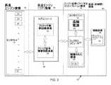
図2は、例えば図1に示す試験スタンド100などの定置試験スタンド上にガスタービンエンジンが取付けられ、動作する間のエンジンの性能パラメータを監視するように構成された、監視システム10の様々なユニットを示すブロック図である。システム10は、オンウイング飛行試験中、並びに航空機の通常の運航中にエンジンを監視するためにも使用できる。監視システム10は特にガスタービンエンジンの監視に適し、便宜上図1のエンジン108及びそのスタンド100を参照して記載するが、システム10の使用はこのような用途に限定されない。むしろ、システム10は、上昇した温度に曝される環境で動作する装置の性能パラメータを監視することが望まれ、又は必要とされる広範な状況により広く利用できる。 FIG. 2 illustrates various units of the
図2に示すように、システム10は一般に、ガスタービンエンジン108に対する4つの環境34、36、38及び40にあるユニット12、14、16及び18を有するものとして特定されている。第1ユニット12は、エンジンの性能を評価する目的で、エンジン108の性能パラメータを監視するために、エンジン108内及びその周囲に適宜配置されたセンサ20のアレイを備える。システム10は任意の数のセンサ20を使用してもよく、センサ20は、図1を参照して前述したように、例えばエンジン108の温度、圧力、流量、力、回転速度などを監視するための様々なタイプのセンサでよい。あるタイプのセンサ20は通常、熱電対、抵抗温度検知器(RTD)、及び圧力変換器を含め、エンジン動作の監視中に大量に使用される。センサ20は対象のパラメータを直に検知するように配置されるので、図2において、センサ20のユニット(アレイ)12は、システム10が200℃を超える最高温度に曝されることが多く、260℃以上にも達することがある「高温エンジン環境」34に置かれるものとして示されている。システム10で使用するのに適するセンサ20は市販され、ガスタービンエンジンのパラメータを監視するために一般に使用されており、従って、本明細書では詳細には記載しない。センサ20が発生する特定の出力信号はセンサ20のタイプによって決まるが、ほとんどの場合、信号はアナログ信号であり、そのデータがエンジンの性能を評価するコンピュータ処理装置によって使用されるようにデジタル化されなければならない。 As shown in FIG. 2, the
システム10の残りの主要ユニット14、16、及び18は、図2において、より低い温度の発生が見込まれる環境36、38、及び40にある。これらのユニットの第1ユニットはハブユニット14と呼ばれ、センサ20は、使用される特定のタイプのセンサと共に一般に使用される任意の適当なワイヤ、チューブ、又はその他の適当なコネクタを介してハブユニットと直接通信する。図2に示すハブユニット14は通常、センサ20の数及び各ハブユニット14が対応できるセンサ20の数に応じて、システム10内で使用し得る幾つかのハブユニット14の1つである。センサ20の環境34と同様に、ハブユニット14の環境36は、ハブユニット14がエンジン108の極めて近傍、例えばエンジンカウル114の下のエンジンコアの環境など、エンジン108の約3メートル以内に位置するようにされているので「高温エンジン環境」34と呼ばれる。エンジン108の真上及びそのカウル114の真下の位置の他に、別の位置には、システム10が依然として極めて高温に曝されるスタンド100のヘッドフレーム106又はアダプタ110上の隣接位置が含まれる。例えば、カウル114の下、又はヘッドフレーム106、又はアダプタ110の隣接位置の温度は125℃を超えることが多く、例えば200℃以上、及び可能性としては260℃以上にも上る極めて高温に達することがある。その結果、ハブユニット14の電子コンポーネントは、従来の電子コンポーネント、更には軍事用標準部品で可能な温度よりも大幅に高い温度に耐えることができなければならない。 The remaining
これに対して、コレクタユニット16及びディストリビュータユニット18と呼ばれるシステム10の残りの2つのユニット16及び18の環境38及び40は、「エンジン近傍環境」38、及び「低温環境」40として特定される。前者がそう呼ばれるのは、コレクタユニット16はエンジン108の近傍に位置するが、ハブユニット14程にはエンジンコアに近くないように配置されているからである。例えば、コレクタユニット16を、エンジン18のコアから約3〜10メートルの距離でエンジンファンケース環境内に、又はヘッド(スラスト)フレーム106などのスタンド100上に配置してもよい。これらの位置では、温度は通常55℃を超えるが、260℃よりは大幅に低く、通常は125℃未満である。その結果、コレクタユニット16の電子コンポーネントは通常、ハブユニット14ほど高くはないが高温に耐えることができなければならない。ある状況では、定格が125℃までの軍用標準部品を使用してもよく、場合によっては定格が85℃までの従来の電子コンポーネントを使用してもよい。 In contrast, the
一方、ディストリビュータユニット18の低温環境40では、定格が85℃未満の従来の電子コンポーネントを使用できる。環境40は、ディストリビュータユニット18が、例えば試験スタンド100の近傍にあり、温度を55℃未満に保つ空調で安定化された密閉施設などの制御された温度環境にあることができ、好ましくは配置されるため「低温」と呼ばれる。オンウイングのエンジン運転では、環境40は航空機内でもよい。ディストリビュータユニット18は好ましくはシステム10の最大の処理力を有しており、従って、一般的に、図2のディストリビュータコンピュータ42によって集合的に示される、データ処理用に構成された1つ又は複数のコンピュータサーバ、パーソナルコンピュータ、及び/又はその他の処理装置を備える。以下に記載するリアルタイムの較正機能に加えて、ディストリビュータコンピュータ42は更に、エンジニアリングユニット変換、システム構成、及びデータベース機能の能力を備えてもよい。ディストリビュータコンピュータ42に適した装置は温度感受性が比較的高いことが多く、従って、概ね室温で格納されることが有利である。低温環境40は通常は、エンジン試験スタンド100から、例えば50メートルを超える遠隔位置にある。 On the other hand, in the
図2は、プロセッサ制御回路基板22と、1つまたは複数のアナログ信号調節回路基板24とを備えるものとしてハブユニット14を概略的に示す。これらの回路基板22及び24は好ましくは、図2に基板22と24とを完全に囲むものとして概略的に示すハウジング44内に封入される。プロセッサ制御回路基板22とアナログ信号調節回路基板24とは協働してセンサ20のアナログ出力信号を、ディストリビュータユニット18による処理が可能なデジタル信号に変換する。本発明の好ましい態様によれば、プロセッサ制御回路基板22及びアナログ信号調節回路基板24は更に連係して、アナログ−デジタル変換の前にセンサ20から受信したアナログ出力信号の完全性を保証するため、追加の処理プロセスを行う。以下により詳細に説明するように、このような追加処理プロセスの1つは、コンポーネントの老化、及びハブユニット14が曝される極端な温度変化などの温度変化の結果生ずることがあるアナログ信号調節回路基板24及びプロセッサ制御回路基板22の電子コンポーネントの精度及び正確度特性の何らかの変動を検知する連続較正機能を備えることである。較正機能は、コレクタユニット16、より具体的にはユニット16のコレクタコンピュータ26を介してハブユニット14から取得したデジタルデータのリアルタイム補正を行うために、ディストリビュータコンピュータ42が使用できる較正データを作成する。別の好ましい処理は、複数のセンサ20のアナログ出力信号を多重化アナログ出力へと多重化して、例えばRS−485シリアル通信ケーブルなどのシリアルデータコネクタを介してデジタルデータをコレクタユニット16に伝送するために必要な接続部品の数を減らす。更に別の好ましい処理プロセスは、多重化されたアナログ出力の個々のアナログ出力信号が出力間でより迅速に「整定」するように、1つのグループ(バンク)のセンサ20の多重化されたアナログ出力に、別のバンクのセンサ20の多重化されたアナログ出力をインターリーブすることである。ハブユニット14の上記及びその他の態様は以下に更に詳細に記載する。 FIG. 2 schematically illustrates the hub unit 14 as comprising a processor
コレクタハブ16は、コレクタコンピュータ26、電源28、及び以下により詳細に説明するように、システム電圧基準デバイス32を含む温度制御環境30を備えるものとして図2に概略的に示されている。電源28の主機能は、(必要に応じた)センサ20と、ハブユニット14内に格納された電子コンポーネントとを含むシステム10の電子コンポーネントに電力を供給することである。好ましい電源28は、スイッチング調整器前端とリニア調整器後端とを有する二重配置設計の電源である。各ハブユニット14に複数の別個に調整される電圧を生成して、システムの故障耐性を高め、ノイズ結合を低減するように、電源28を構成してもよい。コレクタコンピュータ26は、デジタルデータをディストリビュータユニット18のディストリビュータコンピュータ42に転送する前に、ハブユニット14、並びにシステム10に含まれるいずれかの追加のハブユニット14からデジタルデータを受信する。コレクタコンピュータ26は好ましくは、例えば射程間計装グループ(IRIG)のタイムコード、又はネットワークタイムプロトコル(NTP)を使用して、ディストリビュータコンピュータ42へのデジタルデータストリームを同期化するロギング機能を有するように構成される。より具体的には、コレクタコンピュータ26は好ましくは、ハブユニット14から来る複数のデジタルデータストリームを正確にタイムスタンプし、データをフレーム内にパッキングし、次いで、例えばファイバベースのイーサーネット接続を経てデータをディストリビュータコンピュータ42に送信することによって、複数のハブユニット14から受信したデジタルデータ用のインテリジェントスイッチとして動作する。複数のデータストリームをタイムスタンプし、データをフレーム内にパッキングするのに適するコンポーネントは当技術分野ではよく知られているため、本明細書では詳細に記載しない。送信が落雷に影響されることを軽減するために、コレクタコンピュータ26とディストリビュータコンピュータ42との間のデータ接続用の光ファイバケーブルを使用することが好ましく、これは、送信ケーブルは通常、試験スタンド100とディストリビュータユニット18を格納する遠隔位置の施設のハウジングとの間を通される結果、屋外環境に曝されるために望ましい。コレクタコンピュータ26、電源28、及び制御された環境30を全て適当な保護ハウジング(図示せず)内に封入して、これらのコンポーネントが風雨に直に曝されることから保護してもよい。 The collector hub 16 is shown schematically in FIG. 2 as comprising a
特に、ハブユニット14のレベルでの多重化と、コレクタユニット16のレベルでの同期化によって、単一のイーサーネット接続を経てデジタルデータをディストリビュータユニット18に供給することができ、これは、従来センサ出力を先行技術の遠隔データ取得システムに送信するために必要であった通常何千本ものケーブルやチューブとは著しく対照的である。 In particular, multiplexing at the level of the hub unit 14 and synchronization at the level of the collector unit 16 allows digital data to be supplied to the
図3は、プロセッサ制御回路基板22、そのコンポーネントの幾つか、及びアナログ信号調節回路基板24とコレクタユニット16への接続部品を示すブロック図である。プロセッサ制御回路基板22は、EEPROM(電気的に消去可能な読出し専用メモリ)などのROM(読出し専用メモリ)48に記憶されたプログラムによって実行し、RAM(ランダムアクセスメモリ)50を使用してセンサ20から生成されたデジタルデータ、並びに制御回路基板22によって行われる計算に使用される任意の変数を記憶するように構成されたマイクロプロセッサ46を備えるものとして示されている。マイクロプロセッサ46は好ましくは、(以下に記載する)信号調節回路基板24に関連する利得設定機能を実行し、センサ20の個々の信号チャネル、又は信号チャネルのブロックのどれが読出されるか、及びデータ取得、エラー検知、アナログ−デジタル変換、いずれかの組込み試験(BIT)モードの実行、(センサ20のタイプに基づく)センサの適合化、及びデジタルデータの収集、フォーマット化、及びコレクタコンピュータ26への伝送のタイミングを制御/選択する。図3に示すように、回路基板22の入力/出力(I/O)機能は、好ましくはメモリマップI/O動作の形態で実行される。図3に更に示すように、プロセッサ制御回路基板22はゼロ及びフルスケール制御出力をもアナログ信号調節回路基板24に送信し、且つコレクタコンピュータ26と直接通信する。調節回路基板24及び図4を参照して記載するように、制御回路基板22によって送信されるゼロ及びフルスケール制御出力は、温度変化及びコンポーネントの老化に起因する調節回路基板24の電子コンポーネントの精度及び正確度特性の何らかの変動を検知し、補償するためにゼロ電圧と基準電圧とを周期的に印加する連続較正法の一部である。 FIG. 3 is a block diagram showing the processor
前述のように、ハブユニット14は、125℃以上の温度、好ましくは少なくとも200℃の温度で動作することを意図している。好適な実施形態では、マイクロプロセッサ46、ROM48、RAM50、及び制御回路基板22に取付けられる受動コンポーネントは200℃以上の温度で動作することができる。この能力を達成するため、マイクロプロセッサ46、ROM48、及びRAM50は、シリコンオンインシュレータ(SOI)基板及び処理技術で実装される。当技術分野で知られているように、SOI基板は通常、絶縁体上の薄いエピタキシャル層を備える。基板は通常、ウエーハを結合する前に一対の半導体(例えばシリコン)の一方又は両方の結合面を酸化処理することによって形成される。もっとも一般的には、シリコンウエーハ上に形成されたエピタキシャル層上に単一の二酸化シリコン層が成長する。ウエーハを結合した後、二酸化シリコン層が、エピタキシャル層を電気的に絶縁する絶縁体を形成するように、絶縁体とエピタキシャル層(及びオプションとして第2のウエーハのシリコン層)以外の全てがエッチングで除去される。SOI処理技術を利用してSOI基板上に実装されるソリッドステートマイクロプロセッサの商用事例は、ハネウェル社から市販されているHT83C51マイクロプロセッサである。SOI基板上に実装されるRAMの商用事例には、ハネウェル社から市販されているHT6256 256キロビットのSRAMコンポーネントが挙げられ、SOI基板上に実装されるROMの商用事例には、トワイライトテクノロジー社から市販されているROMコンポーネントが挙げられる。 As mentioned above, the hub unit 14 is intended to operate at a temperature of 125 ° C. or higher, preferably at least 200 ° C. In a preferred embodiment, the
プロセッサ制御回路基板22の電子コンポーネントが取付けられる基板は、好ましくは、少なくとも260℃の温度にも耐えることができる。好ましい高温基板材料は、ガラス強化された炭化水素/セラミック積層体であるRO4003Cの名称でロジャースコーポレーションから市販されている。更に、コンポーネントは好ましくは高融点のはんだで固着され、その非限定的な代表例は、融点範囲が約287〜約296℃である92.5Pb−5Sn−2.5Agである。基板の熱膨張及び収縮に起因する熱応力を低減するため、マイクロプロセッサ46、ROM48、RAM50、及び基板22上のその他のコンポーネントは好ましくは、基板内のスルーホール(通常はめっきスルーホール)に挿入され、次いで基板にはんだ付けされる1つ又は複数の金属リード(スティック)を有するスルーホールコンポーネントである。熱応力を低減する別の方法には、熱勾配を最小限にし、熱時間定数と制振性とを高くし、基板の層間剥離及び膨張/収縮により破壊し易い金属化バイアの数を制限するために高温、熱伝導性のポッティング材を使用することが含まれる。特に、スルーホールコンポーネントの金属リードは、これらが内部に配置されるバイアの構造的完全性を促進するものと考えられる。 The board on which the electronic components of the processor
上記の高温性能によって、好ましくは、従来の電子素子に必要であるように制御回路基板22の温度を125℃未満に保つための専用の能動冷却システムを必要とせずに、制御回路基板22をハブユニットハウジング44内に格納することができる。「能動冷却」という用語は、本明細書では伝導、対流、及び/又は放射によって熱を回路基板22からハブユニットハウジング44へと伝達して逃がすために特に設計された冷却システムを意味するために用いられる。 Due to the high temperature performance described above, the
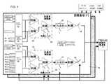
図4は、2つのアナログ信号調節回路基板24、及び図3のプロセッサ制御回路基板22へのその接続を示すブロック図である。アナログ信号調節回路基板24は、ハブユニット14のハウジング44内でプロセッサ制御回路基板22と組み合わされ、従ってこれもエンジン108の過酷な環境での高温で動作する必要がある。ハブユニット14、及びその調節回路基板24の高温動作によって、熱電対、RTD、及び圧力変換器を含むセンサ20がエンジン108上で直接終端し、プロセッサ制御回路基板22によって実行されるA/D(アナログ−デジタル)変換の前にそれらの出力が調節されることが可能になる。更に、調節回路基板24のハードウエアは好ましくは、前述の連続較正、多重化、及びインターリーブ機能を組み込んでいる。 FIG. 4 is a block diagram illustrating two analog signal
前述のように、調節回路基板24上で実行される連続較正法は較正データを作成し、ディストリビュータコンピュータ42はこのデータを使用して、ハブユニット14から取得したデジタルデータのリアルタイムの修正を行う。連続較正法は好ましくは、信号の精度を大幅に損なうことがある調節回路基板24及びプロセッサ制御回路基板22の全ての受動及び能動コンポーネントを補償する。連続較正機能が必要であるのは、システムレベルで、例えば約−55℃から200℃以上までのハブユニット14の予測動作範囲にわたって変動を呈することのない個別コンポーネントを現在は入手できないからである。本発明の好適な実施形態では、連続較正法はゼロ及びフルスケールデータを連続的に収集する一方で、時間及び温度に関する取得データの変動があればこれを自動的に補償する。 As described above, the continuous calibration method performed on the
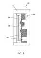
連続較正機能の一部は、ハブユニット14から離隔したコレクタユニット16の制御された環境30に配置されるものとして図2に示すシステム電圧基準デバイス32に依拠する。コレクタユニット16内の位置が好ましいと考えられるが、システム電圧基準デバイス32を別の位置に配置しても適切であることが予測される。制御された環境30は、加熱素子54、銅板56、及び電圧基準デバイス32の均一な加熱を達成する熱RTVポッティング材58を更に含むハウジング52内に格納された電圧基準デバイス32を備えるものとして図5により詳細に概略的に示されている。基準デバイス32の温度は、例えば約55℃から約125℃などの任意の適当なレベルに調整できる。基準デバイス32は、高精度のゼロ及びフルスケール基準電圧を生成し、次いで専用の差動リンクを経て調節回路基板24に送られる。 Part of the continuous calibration function relies on the system
温度に誘発される調節回路基板24の電気回路コンポーネントの精度及び正確度の変動は、A/D変換中にセンサ20のアナログ出力信号と共に取り込まれ、記録される。アナログ出力信号がセンサ20から読み取られる各サイクル中に、プロセッサ制御回路基板22によって基準デバイス32の高精度のゼロボルト及び基準電圧信号が、各調節回路基板24の電子コンポーネントによって画成される全てのアナログ信号処理経路(チャネル)を経て送信される。次いで、以前の較正読取り値からの出力電圧の変化が基板レベルのコンポーネント変動に起因し、データが更に使用される前にデジタル化されたセンサデータをデジタル修正するディストリビュータコンピュータ42に前記変化が較正データとして送信されることによって、デジタル化されたセンサデータを修正するためにゼロボルト及び基準電圧信号が使用される。実際には、ゼロ及びフルスケール基準信号は毎秒数回印加されてもよい。前述の連続較正機能によって、約∀20ppm(百万分率)未満程度の精度を有する時間、温度、及び距離にわたる精度がアナログ信号処理経路内で達成された。 Variations in accuracy and accuracy of the electrical circuit components of the
較正法の一部として、調節回路基板24は更に、センサ20からの複数の信号チャネルの多重化を行い、それによって各調節回路基板24は、例えば図4に示す2つなどのより少ない数の回路経路を経て複数のセンサ信号を調節することが可能になる。複数のセンサ20からの信号は、マルチプレキサ60を通過して多重化されたアナログ出力を生成するのもとして図4に示され、それによってシリアルデータコネクタを経てデジタルデータをコレクタユニット16に送信するために必要な接続部品の数が減少する。各回路経路内で、多重化されたアナログ出力は計装用演算増幅器62で調節される。図4に、各増幅器62は、各調節回路基板24を使用して異なる電圧出力の様々なタイプのセンサをA/D変換の前に設定された出力電圧にスケーリングすることを可能にするプロセッサ制御回路基板22によって制御可能な能動利得変化64を組み込むものとして示されている。 As part of the calibration method, the
図4から更に明らかなように、スイッチ68を使用して、回路基板24上の1つの回路経路に沿ったセンサ20の1つのバンク(グループ)の多重化されたアナログ出力に、同じ回路基板24の別の回路経路上の別のバンクのセンサ20の多重化されたアナログ出力をインターリーブして、システムスループットを向上させることができる。1つのバンクのセンサ20からの多重化された一連のアナログ出力がプロセッサ制御回路基板22のA/D変換に出力される際に、別のバンクのセンサ20上のセンサ出力は様々な整定段階にある。第1のバンクのセンサ20からの一連の多重化されたアナログ出力がA/D変換器によって読取られた後、第1のバンクの信号が別のセンサ20上で整定され始める間に次のバンクを選択することができる。この機能によって、プロセッサ制御回路基板22及び調節回路基板24のより緩速であるがより高温に耐える回路コンポーネントでより高いシステムレベルの処理能力が可能になる。 As is further apparent from FIG. 4, a
図4に示す調節回路基板24は更に、各演算増幅器62の増幅器出力上の動的な双時定数フィルタリング66を組み込み、プロセッサ制御回路基板22によって制御されるものとして示されている。この機能によって更に、多重化されたアナログ出力がそれを経て送信される回路経路間の切換え時の迅速な整定が可能になり、しかも依然としてエンジン試験環境にあるセンサ出力信号の電気的ノイズを低減する高レベルの低域フィルタリングがなされる。動的フィルタリングは、例えばRC回路からの抵抗を除去することによって達成可能であり、1つのチャネル電圧から別のチャネル電圧への迅速な出力変更が可能になり、次いで抵抗を再度回路内に切換えて、センサのノイズとリップルとを最小限にし、A/D変換器(ADC)に提供されるアナログデータの品質を高めることができる。 The
特に、各調節回路基板24は好ましくは、例えばセンサ20が、熱電対及び負の電圧を出力可能な圧力変換器を含む場合、正と負の両方の入力電圧を受け入れることが可能である。加えて、調節回路基板24はハブユニット14の高温環境に位置しているので、従来は熱電対基板上で行われた「冷接点」補償を「熱接点」補償にすることができる。なぜなら、センサ20間の熱電対は、調節回路基板24によって測定されるワイヤと基準電圧との接点よりも低温にあってもよいからである。このため、計装用演算増幅器62は好ましくは、差動電圧での動作に耐えることができ、A/D変換のためにこれらの∀電圧を正だけの電圧範囲にスケーリングする。 In particular, each
プロセッサ制御回路基板22の場合と同様に、アナログ信号調節回路基板24の回路コンポーネントは好ましくは、少なくとも200℃の温度での基板24の動作を可能にするSOI技術で実装され、ハブユニット14全体がこのような上昇した温度で動作することを可能にする。その結果、ハブユニット14及びその制御回路基板22及び調整回路基板24は、それぞれ個々のセンサ出力がワイヤ又はチューブによって試験中のエンジンからかなりの距離を隔てた遠隔位置に送信されなければならない先行技術の限界を克服する。このような制約の結果、エンジンからデータ取得システムに通されるワイヤやチューブが長くなり、更なる費用がかかり、追加のエラー源が生じ、インストールとデバッグのために相当量の労働時間が必要となる。これに対して、ハブユニット14をヘッドフレーム106、そのアダプタ110上に直接、又はエンジン108上に、例えばカウル114の下に直接配置することができ、その結果、センサ20とハブユニット14上のその終端との間の距離が比較的短縮される(例えば3メートル未満)。 As with the processor
本発明を好適な実施形態によって記載したが、当業者によって別の形態を採用できることは明らかである。例えば、ユニット12、14、16及び18とコンポーネントの物理的構成は図示したものと異なっていてもよく、材料及び処理工程は記載のものと異なるものも使用できよう。従って、本発明の範囲は以下の請求項によってのみ限定される。 While the invention has been described in terms of a preferred embodiment, it is apparent that other forms can be adopted by one skilled in the art. For example, the physical configurations of
100 スタンド
102 支柱
104 土台
106 フレーム
108 エンジン
110 アダプタ
112 パイロン
114 ナセル100
Claims (10)
Translated fromJapanese前記装置(108)に取付けられ、該装置の性能パラメータを検知し、アナログセンサ出力を生成するセンサ(20)と、
125℃を超える第1の温度に曝されるように前記装置(108)に十分に近接して取付けられる少なくとも1つのハブユニット(14)であって、前記センサ(20)からのアナログセンサ出力を受ける手段と、制御回路基板(22)と、少なくとも1つの信号調節回路基板(24)とを備え、前記制御回路基板(22)と前記信号調節回路基板(24)とが協働して動作し、前記アナログセンサ出力を調整し、対応するデジタルデータを生成する構成のハブユニット(14)と、
前記第1の温度未満の第2の温度に曝されるように前記装置(108)に十分に近接して取付けられるコレクタユニット(16)であって、電源(28)と、前記ハブユニット(14)からデジタルデータを受ける手段とを備え、前記電源(28)が前記ハブユニット(14)の前記コレクタユニット(16)と、前記制御回路基板(22)と、前記信号調節回路基板(24)、及び前記センサ(20)に電力を供給する構成のコレクタユニット(16)と、
前記第2の温度未満の第3の温度に曝されるように前記装置(108)から十分に離れた位置にあるディストリビュータコンピュータユニット(18)であって、前記コレクタユニット(16)からデジタルデータを受ける手段と、前記デジタルデータを処理して前記装置(108)の前記性能パラメータを評価する手段とを備える構成のディストリビュータコンピュータユニット(18)とを備える、監視システム(10)。A monitoring system (10) for monitoring performance parameters of a device (108) operating at an elevated temperature,
A sensor (20) attached to the device (108) for sensing performance parameters of the device and generating an analog sensor output;
At least one hub unit (14) mounted in close proximity to the device (108) to be exposed to a first temperature in excess of 125 ° C, wherein the analog sensor output from the sensor (20) is Means for receiving, a control circuit board (22), and at least one signal conditioning circuit board (24), wherein the control circuit board (22) and the signal conditioning circuit board (24) operate in cooperation. A hub unit (14) configured to adjust the analog sensor output and generate corresponding digital data;
A collector unit (16) mounted sufficiently close to the device (108) to be exposed to a second temperature less than the first temperature, the power supply (28) and the hub unit (14) ), And the power source (28) includes the collector unit (16) of the hub unit (14), the control circuit board (22), the signal conditioning circuit board (24), And a collector unit (16) configured to supply power to the sensor (20);
A distributor computer unit (18) located sufficiently away from the device (108) to be exposed to a third temperature less than the second temperature, wherein the digital data from the collector unit (16) A monitoring system (10) comprising: means for receiving; and a distributor computer unit (18) configured to process the digital data and evaluate the performance parameters of the device (108).
基準電圧とゼロ電圧とを前記信号調節回路基板(24)に周期的に印加することによって連続的な較正法を実行して、前記制御回路基板(22)と前記信号調節回路基板(24)との電気回路コンポーネント(46、48,50)の変動に起因する前記アナログ信号処理経路内のエラーを判定し、除去する手段を更に備えることを特徴とする、監視システム(10)。The control circuit board (22) and the signal conditioning circuit board (24) define an analog signal processing path, component aging, and the change in the first temperature to which the hub unit (14) is exposed. Electrical circuit components (46, 48, 50) having accuracy and accuracy characteristics that vary depending on the system, the collector unit (16) includes a system voltage reference device (32) and the system voltage reference device (32). 6. A device as claimed in claim 1, comprising a housing (30) for storing means (54, 56, 58) for maintaining a regulated temperature and the system voltage reference device (32) for generating a reference voltage. The monitoring system (10) of claim 1, wherein the system is
A continuous calibration method is performed by periodically applying a reference voltage and a zero voltage to the signal conditioning circuit board (24), and the control circuit board (22) and the signal conditioning circuit board (24) The monitoring system (10), further comprising means for determining and eliminating errors in the analog signal processing path due to variations in the electrical circuit components (46, 48, 50) of
前記個々の多重化アナログ出力の前記アナログセンサ出力をスケーリングし、対応する前記デジタルデータがそれをもとに生成される個々の調節された多重化アナログ出力を生成するための、利得(64)を調整可能な少なくとも1つの増幅器(62)とを更に備え、前記増幅器(62)及び前記調整可能な利得(64)は、前記制御回路基板(22)に制御される、請求項1から7のいずれか一項に記載の監視システム(10)。Means (60, 62, 64) on the signal conditioning circuit board (24) for multiplexing the plurality of analog sensor outputs generated by the sensor (20) to generate individual multiplexed analog outputs;
Gain (64) for scaling the analog sensor output of the individual multiplexed analog outputs to produce individual adjusted multiplexed analog outputs from which the corresponding digital data is generated. 8. An adjustable amplifier (62), the amplifier (62) and the adjustable gain (64) controlled by the control circuit board (22). A monitoring system (10) according to any one of the preceding claims.
Applications Claiming Priority (2)
| Application Number | Priority Date | Filing Date | Title |
|---|---|---|---|
| US12/977,188US8668381B2 (en) | 2010-12-23 | 2010-12-23 | High temperature electronic monitoring system |
| US12/977,188 | 2010-12-23 |
Publications (3)
| Publication Number | Publication Date |
|---|---|
| JP2012132457Atrue JP2012132457A (en) | 2012-07-12 |
| JP2012132457A5 JP2012132457A5 (en) | 2015-02-19 |
| JP5967928B2 JP5967928B2 (en) | 2016-08-10 |
Family
ID=45418368
Family Applications (1)
| Application Number | Title | Priority Date | Filing Date |
|---|---|---|---|
| JP2011281129AExpired - Fee RelatedJP5967928B2 (en) | 2010-12-23 | 2011-12-22 | High temperature electronic monitoring system |
Country Status (4)
| Country | Link |
|---|---|
| US (1) | US8668381B2 (en) |
| EP (1) | EP2469038A3 (en) |
| JP (1) | JP5967928B2 (en) |
| CA (1) | CA2761375A1 (en) |
Families Citing this family (1)
| Publication number | Priority date | Publication date | Assignee | Title |
|---|---|---|---|---|
| CN113182198B (en)* | 2020-01-14 | 2023-08-29 | 鸿劲精密股份有限公司 | Testing device with temperature control unit and testing classification equipment applied by same |
Citations (10)
| Publication number | Priority date | Publication date | Assignee | Title |
|---|---|---|---|---|
| JP2001329861A (en)* | 2000-05-18 | 2001-11-30 | Mitsubishi Heavy Ind Ltd | Remote supervisory method for gas turbine |
| US6434473B1 (en)* | 1999-10-05 | 2002-08-13 | Honda Giken Kogyo Kabushiki Kaisha | Gas turbine aeroengine control system |
| JP2004028092A (en)* | 2002-05-31 | 2004-01-29 | General Electric Co <Ge> | Automatic engine protection system acted when electronic component of control system is exposed to overheated state |
| JP2004257388A (en)* | 2003-02-26 | 2004-09-16 | General Electric Co <Ge> | Method and device for detecting emergency sensor fault |
| JP2004316649A (en)* | 2003-04-04 | 2004-11-11 | General Electric Co <Ge> | Method and device for monitoring gas turbine combustion dynamics |
| US20050096873A1 (en)* | 2002-12-30 | 2005-05-05 | Renata Klein | Method and system for diagnostics and prognostics of a mechanical system |
| US20050213548A1 (en)* | 2004-03-24 | 2005-09-29 | Benson Dwayne M | Aircraft engine sensor network using wireless sensor communication modules |
| JP2005315237A (en)* | 2004-03-31 | 2005-11-10 | Honda Motor Co Ltd | Sensor failure detection device for gas turbine engine |
| JP2006105981A (en)* | 2004-09-30 | 2006-04-20 | General Electric Co <Ge> | System and method for sensor verification and fusion |
| JP2010255630A (en)* | 2009-04-21 | 2010-11-11 | Hamilton Sundstrand Corp | Reconfigurable transporter monitoring device, module type transporter monitoring system and monitoring method of data supply source |
Family Cites Families (17)
| Publication number | Priority date | Publication date | Assignee | Title |
|---|---|---|---|---|
| US3995485A (en)* | 1975-10-20 | 1976-12-07 | The United States Of America As Represented By The United States Energy Research And Development Administration | Dry, portable calorimeter for nondestructive measurement of the activity of nuclear fuel |
| US4188617A (en)* | 1976-09-29 | 1980-02-12 | Gulf & Western Industries, Inc. | System for converting analog signals to multiplexed digital data |
| US4539652A (en)* | 1982-07-16 | 1985-09-03 | At&T Bell Laboratories | Networks for data communication |
| US4881184A (en)* | 1987-09-08 | 1989-11-14 | Datac, Inc. | Turbine monitoring apparatus |
| US5734596A (en)* | 1994-04-26 | 1998-03-31 | The United States Of America As Represented By Administrator National Aeronautics And Space Administration | Self-calibrating and remote programmable signal conditioning amplifier system and method |
| US5838588A (en)* | 1996-12-13 | 1998-11-17 | Siemens Corporate Research, Inc. | Graphical user interface system for steam turbine operating conditions |
| US6115654A (en)* | 1997-12-23 | 2000-09-05 | Simmonds Precision Products, Inc. | Universal sensor interface system and method |
| DE19806121C2 (en)* | 1998-02-14 | 2001-10-18 | Rolls Royce Deutschland | Device for determining various pressure values in a rotating system |
| US6744376B1 (en)* | 1998-08-26 | 2004-06-01 | The Johns Hopkins University | Remote input/output (RIO) smart sensor analog-digital chip |
| CA2314573C (en)* | 2000-01-13 | 2009-09-29 | Z.I. Probes, Inc. | System for acquiring data from a facility and method |
| US6414612B1 (en)* | 2000-09-14 | 2002-07-02 | Scientific-Atlanta, Inc. | Enhanced bandwidth digitizer using multiple analog-to digital converters and self calibration |
| US20050088316A1 (en) | 2003-10-24 | 2005-04-28 | Honeywell International Inc. | Well control and monitoring system using high temperature electronics |
| US7739216B2 (en) | 2004-04-22 | 2010-06-15 | General Electric Company | Methods and systems for monitoring and diagnosing machinery by incremently testing a rule |
| US20060041368A1 (en) | 2004-08-18 | 2006-02-23 | General Electric Company | Systems, Methods and Computer Program Products for Remote Monitoring of Turbine Combustion Dynamics |
| US8485137B2 (en)* | 2005-01-26 | 2013-07-16 | Noritz Corporation | Combustion control device |
| CN103116565A (en)* | 2005-04-21 | 2013-05-22 | 提琴存储器公司 | Configurable switching element, interconnection network and interconnection method among networks |
| US8161806B1 (en)* | 2010-12-23 | 2012-04-24 | General Electric Company | Method of monitoring engine performance parameters of a gas turbine engine |
- 2010
- 2010-12-23USUS12/977,188patent/US8668381B2/enactiveActive
- 2011
- 2011-12-02EPEP11191716.7Apatent/EP2469038A3/ennot_activeWithdrawn
- 2011-12-08CACA2761375Apatent/CA2761375A1/ennot_activeAbandoned
- 2011-12-22JPJP2011281129Apatent/JP5967928B2/ennot_activeExpired - Fee Related
Patent Citations (12)
| Publication number | Priority date | Publication date | Assignee | Title |
|---|---|---|---|---|
| US6434473B1 (en)* | 1999-10-05 | 2002-08-13 | Honda Giken Kogyo Kabushiki Kaisha | Gas turbine aeroengine control system |
| JP2001329861A (en)* | 2000-05-18 | 2001-11-30 | Mitsubishi Heavy Ind Ltd | Remote supervisory method for gas turbine |
| US20030014219A1 (en)* | 2000-05-18 | 2003-01-16 | Yujiro Shimizu | Method for remote monitoring of gas turbine |
| JP2004028092A (en)* | 2002-05-31 | 2004-01-29 | General Electric Co <Ge> | Automatic engine protection system acted when electronic component of control system is exposed to overheated state |
| US20050096873A1 (en)* | 2002-12-30 | 2005-05-05 | Renata Klein | Method and system for diagnostics and prognostics of a mechanical system |
| JP2004257388A (en)* | 2003-02-26 | 2004-09-16 | General Electric Co <Ge> | Method and device for detecting emergency sensor fault |
| JP2004316649A (en)* | 2003-04-04 | 2004-11-11 | General Electric Co <Ge> | Method and device for monitoring gas turbine combustion dynamics |
| US6990432B1 (en)* | 2003-04-04 | 2006-01-24 | General Electric Company | Apparatus and method for performing gas turbine adjustment |
| US20050213548A1 (en)* | 2004-03-24 | 2005-09-29 | Benson Dwayne M | Aircraft engine sensor network using wireless sensor communication modules |
| JP2005315237A (en)* | 2004-03-31 | 2005-11-10 | Honda Motor Co Ltd | Sensor failure detection device for gas turbine engine |
| JP2006105981A (en)* | 2004-09-30 | 2006-04-20 | General Electric Co <Ge> | System and method for sensor verification and fusion |
| JP2010255630A (en)* | 2009-04-21 | 2010-11-11 | Hamilton Sundstrand Corp | Reconfigurable transporter monitoring device, module type transporter monitoring system and monitoring method of data supply source |
Also Published As
| Publication number | Publication date |
|---|---|
| US8668381B2 (en) | 2014-03-11 |
| EP2469038A3 (en) | 2018-01-24 |
| CA2761375A1 (en) | 2012-06-23 |
| EP2469038A2 (en) | 2012-06-27 |
| JP5967928B2 (en) | 2016-08-10 |
| US20120163408A1 (en) | 2012-06-28 |
Similar Documents
| Publication | Publication Date | Title |
|---|---|---|
| JP5973718B2 (en) | Method for monitoring engine performance parameters of a gas turbine engine | |
| EP2318895B1 (en) | Wireless telemetry circuit structure for measuring temperature in high temperature environments | |
| US9733131B2 (en) | Thermocouple | |
| EP2329227B1 (en) | A wireless telemetry electronic circuit package for high temperature environments | |
| US8661881B2 (en) | Hub unit for a high temperature electronic monitoring system | |
| US20150000303A1 (en) | Wireless power for gas turbine engine instrumentation | |
| JP6001850B2 (en) | Hub unit for high temperature electronic monitoring system | |
| JP5967928B2 (en) | High temperature electronic monitoring system | |
| Ainsworth et al. | Developments in instrumentation and processing for transient heat transfer measurement in a full-stage model turbine | |
| EP2867636B1 (en) | Electronic circuitry for high-temperature environments | |
| Mu¨ ller et al. | Capacitive measurement of compressor and turbine blade tip to casing running clearance | |
| CN110388990A (en) | A Wireless Telemetry System for Temperature Measurement of Engine Rotating Parts | |
| US11591929B2 (en) | Sensor assemblies, gas turbines with sensor assemblies, and methods of cooling sensor assemblies | |
| Long et al. | Telemetry system integrated in a small gas turbine engine | |
| EP0626571B1 (en) | An integrated temperature measuring unit with thermocouples | |
| CN119618415A (en) | Multi-point temperature measurement system and method in rotation state | |
| Mersinligil et al. | A high temperature high bandwidth fast response total pressure probe for measurements in a multistage axial compressor | |
| Solaro | Investigation of Sensor Faults in a Gas Turbine | |
| Long et al. | Application of a Miniature Telemetry System in a Small Gas Turbine Engine | |
| Mönich et al. | Capacitive Measurement System for Blade Clearances | |
| Delio et al. | Instrumentation for Recording Transient Performance of Gas-turbine Engines and Control Systems | |
| Balazic et al. | Accuracies of digital engine monitoring proven by performance | |
| Edwards | AIR 1900 GUIDE TO TEMPERATURE MONITORING IN AIRCRAFT GAS TURBINE ENGINES |
Legal Events
| Date | Code | Title | Description |
|---|---|---|---|
| A521 | Written amendment | Free format text:JAPANESE INTERMEDIATE CODE: A523 Effective date:20141218 | |
| A621 | Written request for application examination | Free format text:JAPANESE INTERMEDIATE CODE: A621 Effective date:20141218 | |
| A977 | Report on retrieval | Free format text:JAPANESE INTERMEDIATE CODE: A971007 Effective date:20151222 | |
| A131 | Notification of reasons for refusal | Free format text:JAPANESE INTERMEDIATE CODE: A131 Effective date:20160126 | |
| A521 | Written amendment | Free format text:JAPANESE INTERMEDIATE CODE: A523 Effective date:20160216 | |
| TRDD | Decision of grant or rejection written | ||
| A01 | Written decision to grant a patent or to grant a registration (utility model) | Free format text:JAPANESE INTERMEDIATE CODE: A01 Effective date:20160607 | |
| A61 | First payment of annual fees (during grant procedure) | Free format text:JAPANESE INTERMEDIATE CODE: A61 Effective date:20160705 | |
| R150 | Certificate of patent or registration of utility model | Ref document number:5967928 Country of ref document:JP Free format text:JAPANESE INTERMEDIATE CODE: R150 | |
| LAPS | Cancellation because of no payment of annual fees |