JP2012129565A - Exposure equipment, exposure method, and device manufacturing method - Google Patents
Exposure equipment, exposure method, and device manufacturing methodDownload PDFInfo
- Publication number
- JP2012129565A JP2012129565AJP2012083140AJP2012083140AJP2012129565AJP 2012129565 AJP2012129565 AJP 2012129565AJP 2012083140 AJP2012083140 AJP 2012083140AJP 2012083140 AJP2012083140 AJP 2012083140AJP 2012129565 AJP2012129565 AJP 2012129565A
- Authority
- JP
- Japan
- Prior art keywords
- liquid
- substrate
- recovery
- exposure apparatus
- optical system
- Prior art date
- Legal status (The legal status is an assumption and is not a legal conclusion. Google has not performed a legal analysis and makes no representation as to the accuracy of the status listed.)
- Granted
Links
Images


Classifications
- G—PHYSICS
- G03—PHOTOGRAPHY; CINEMATOGRAPHY; ANALOGOUS TECHNIQUES USING WAVES OTHER THAN OPTICAL WAVES; ELECTROGRAPHY; HOLOGRAPHY
- G03F—PHOTOMECHANICAL PRODUCTION OF TEXTURED OR PATTERNED SURFACES, e.g. FOR PRINTING, FOR PROCESSING OF SEMICONDUCTOR DEVICES; MATERIALS THEREFOR; ORIGINALS THEREFOR; APPARATUS SPECIALLY ADAPTED THEREFOR
- G03F7/00—Photomechanical, e.g. photolithographic, production of textured or patterned surfaces, e.g. printing surfaces; Materials therefor, e.g. comprising photoresists; Apparatus specially adapted therefor
- G03F7/70—Microphotolithographic exposure; Apparatus therefor
- G03F7/70691—Handling of masks or workpieces
- G03F7/70733—Handling masks and workpieces, e.g. exchange of workpiece or mask, transport of workpiece or mask
- G—PHYSICS
- G03—PHOTOGRAPHY; CINEMATOGRAPHY; ANALOGOUS TECHNIQUES USING WAVES OTHER THAN OPTICAL WAVES; ELECTROGRAPHY; HOLOGRAPHY
- G03F—PHOTOMECHANICAL PRODUCTION OF TEXTURED OR PATTERNED SURFACES, e.g. FOR PRINTING, FOR PROCESSING OF SEMICONDUCTOR DEVICES; MATERIALS THEREFOR; ORIGINALS THEREFOR; APPARATUS SPECIALLY ADAPTED THEREFOR
- G03F7/00—Photomechanical, e.g. photolithographic, production of textured or patterned surfaces, e.g. printing surfaces; Materials therefor, e.g. comprising photoresists; Apparatus specially adapted therefor
- G03F7/20—Exposure; Apparatus therefor
- G03F7/2041—Exposure; Apparatus therefor in the presence of a fluid, e.g. immersion; using fluid cooling means
- G—PHYSICS
- G03—PHOTOGRAPHY; CINEMATOGRAPHY; ANALOGOUS TECHNIQUES USING WAVES OTHER THAN OPTICAL WAVES; ELECTROGRAPHY; HOLOGRAPHY
- G03F—PHOTOMECHANICAL PRODUCTION OF TEXTURED OR PATTERNED SURFACES, e.g. FOR PRINTING, FOR PROCESSING OF SEMICONDUCTOR DEVICES; MATERIALS THEREFOR; ORIGINALS THEREFOR; APPARATUS SPECIALLY ADAPTED THEREFOR
- G03F7/00—Photomechanical, e.g. photolithographic, production of textured or patterned surfaces, e.g. printing surfaces; Materials therefor, e.g. comprising photoresists; Apparatus specially adapted therefor
- G03F7/70—Microphotolithographic exposure; Apparatus therefor
- G03F7/70216—Mask projection systems
- G03F7/70341—Details of immersion lithography aspects, e.g. exposure media or control of immersion liquid supply
- G—PHYSICS
- G03—PHOTOGRAPHY; CINEMATOGRAPHY; ANALOGOUS TECHNIQUES USING WAVES OTHER THAN OPTICAL WAVES; ELECTROGRAPHY; HOLOGRAPHY
- G03F—PHOTOMECHANICAL PRODUCTION OF TEXTURED OR PATTERNED SURFACES, e.g. FOR PRINTING, FOR PROCESSING OF SEMICONDUCTOR DEVICES; MATERIALS THEREFOR; ORIGINALS THEREFOR; APPARATUS SPECIALLY ADAPTED THEREFOR
- G03F7/00—Photomechanical, e.g. photolithographic, production of textured or patterned surfaces, e.g. printing surfaces; Materials therefor, e.g. comprising photoresists; Apparatus specially adapted therefor
- G03F7/70—Microphotolithographic exposure; Apparatus therefor
- G03F7/708—Construction of apparatus, e.g. environment aspects, hygiene aspects or materials
- G03F7/7095—Materials, e.g. materials for housing, stage or other support having particular properties, e.g. weight, strength, conductivity, thermal expansion coefficient
- H—ELECTRICITY
- H01—ELECTRIC ELEMENTS
- H01L—SEMICONDUCTOR DEVICES NOT COVERED BY CLASS H10
- H01L21/00—Processes or apparatus adapted for the manufacture or treatment of semiconductor or solid state devices or of parts thereof
- H01L21/02—Manufacture or treatment of semiconductor devices or of parts thereof
- H01L21/027—Making masks on semiconductor bodies for further photolithographic processing not provided for in group H01L21/18 or H01L21/34
- H01L21/0271—Making masks on semiconductor bodies for further photolithographic processing not provided for in group H01L21/18 or H01L21/34 comprising organic layers
- H01L21/0273—Making masks on semiconductor bodies for further photolithographic processing not provided for in group H01L21/18 or H01L21/34 comprising organic layers characterised by the treatment of photoresist layers
Landscapes
- General Physics & Mathematics (AREA)
- Physics & Mathematics (AREA)
- Engineering & Computer Science (AREA)
- Public Health (AREA)
- Environmental & Geological Engineering (AREA)
- Epidemiology (AREA)
- Health & Medical Sciences (AREA)
- Condensed Matter Physics & Semiconductors (AREA)
- Manufacturing & Machinery (AREA)
- Computer Hardware Design (AREA)
- Microelectronics & Electronic Packaging (AREA)
- Power Engineering (AREA)
- Exposure And Positioning Against Photoresist Photosensitive Materials (AREA)
- Exposure Of Semiconductors, Excluding Electron Or Ion Beam Exposure (AREA)
- User Interface Of Digital Computer (AREA)
Abstract
Translated fromJapaneseDescription
Translated fromJapanese本発明は、投影光学系と基板との間に液浸領域を形成した状態で基板にパターンを露光する露光装置、露光方法及びデバイス製造方法に関するものである。 The present invention relates to an exposure apparatus, an exposure method, and a device manufacturing method for exposing a pattern on a substrate in a state where an immersion region is formed between a projection optical system and the substrate.
半導体デバイスや液晶表示デバイスは、マスク上に形成されたパターンを感光性の基板上に転写する、いわゆるフォトリソグラフィの手法により製造される。このフォトリソグラフィ工程で使用される露光装置は、マスクを支持するマスクステージと基板を支持する基板ステージとを有し、マスクステージ及び基板ステージを逐次移動しながらマスクのパターンを投影光学系を介して基板に転写するものである。近年、デバイスパターンのより一層の高集積化に対応するために投影光学系の更なる高解像度化が望まれている。投影光学系の解像度は、使用する露光波長が短いほど、また投影光学系の開口数が大きいほど高くなる。そのため、露光装置で使用される露光波長は年々短波長化しており、投影光学系の開口数も増大している。そして、現在主流の露光波長はKrFエキシマレーザの248nmであるが、更に短波長のArFエキシマレーザの193nmも実用化されつつある。
また、露光を行う際には、解像度と同様に焦点深度(DOF)も重要となる。解像度R、及び焦点深度δはそれぞれ以下の式で表される。
R=k1・λ/NA … (1)
δ=±k2・λ/NA2 … (2)Semiconductor devices and liquid crystal display devices are manufactured by a so-called photolithography technique in which a pattern formed on a mask is transferred onto a photosensitive substrate. An exposure apparatus used in this photolithography process has a mask stage for supporting a mask and a substrate stage for supporting a substrate, and a mask pattern is transferred via a projection optical system while sequentially moving the mask stage and the substrate stage. It is transferred to the substrate. In recent years, in order to cope with higher integration of device patterns, higher resolution of the projection optical system is desired. The resolution of the projection optical system becomes higher as the exposure wavelength used is shorter and the numerical aperture of the projection optical system is larger. Therefore, the exposure wavelength used in the exposure apparatus is shortened year by year, and the numerical aperture of the projection optical system is also increasing. The mainstream exposure wavelength is 248 nm of the KrF excimer laser, but the 193 nm of the shorter wavelength ArF excimer laser is also being put into practical use.
Also, when performing exposure, the depth of focus (DOF) is important as well as the resolution. The resolution R and the depth of focus δ are each expressed by the following equations.
R = k1 · λ / NA (1)
δ = ± k2 · λ / NA2 (2)
ここで、λは露光波長、NAは投影光学系の開口数、k1、k2はプロセス係数である。(1)式、(2)式より、解像度Rを高めるために、露光波長λを短くして、開口数NAを大きくすると、焦点深度δが狭くなることが分かる。Here, λ is the exposure wavelength, NA is the numerical aperture of the projection optical system, and k1 and k2 are process coefficients. From the equations (1) and (2), it can be seen that the depth of focus δ becomes narrower when the exposure wavelength λ is shortened and the numerical aperture NA is increased in order to increase the resolution R.
焦点深度δが狭くなり過ぎると、投影光学系の像面に対して基板表面を合致させることが困難となり、露光動作時のマージンが不足するおそれがある。そこで、実質的に露光波長を短くして、且つ焦点深度を広くする方法として、例えば下記特許文献1に開示されている液浸法が提案されている。この液浸法は、投影光学系の下面と基板表面との間を水や有機溶媒等の液体で満たして液浸領域を形成し、液体中での露光光の波長が空気中の1/n(nは液体の屈折率で通常1.2〜1.6程度)になることを利用して解像度を向上するとともに、焦点深度を約n倍に拡大するというものである。 If the depth of focus δ becomes too narrow, it becomes difficult to match the substrate surface with the image plane of the projection optical system, and the margin during the exposure operation may be insufficient. Therefore, as a method for substantially shortening the exposure wavelength and increasing the depth of focus, for example, a liquid immersion method disclosed in
ところで、上記従来技術には以下に述べる問題が存在する。 By the way, the above-described prior art has the following problems.
上記従来技術は基板を所定方向に移動しつつ走査露光する際に投影光学系と基板との間に液浸領域を形成できるため有効であるが、基板の移動方向に関して、マスクのパターンの像が投影される投影領域の手前で液体を供給する構成であって、液体を投影領域の手前側から基板の移動方向に沿って一方向に流す構成である。そして、基板の移動方向を前記所定方向から反対方向に切り替える際、液体を供給する位置(ノズル)も切り替える構成である。ところが、この切り替え時に投影領域に対して一方向からの液体の供給を急に停止して他方向からの液体の供給を開始することになるため、投影光学系と基板との間で液体の振動(所謂ウォーターハンマー現象)が発生したり、液体供給装置自体(供給管や供給ノズルなど)に振動が発生して、パターン像の劣化を引き起こすという問題が生じたり、また、投影領域に対して一方向から液体を流す構成であるため、投影光学系と基板との間に液浸領域が十分に形成されない場合が起きるという問題も生じることが解明されてきた。 The above prior art is effective because a liquid immersion region can be formed between the projection optical system and the substrate when scanning exposure is performed while moving the substrate in a predetermined direction. The liquid is supplied in front of the projection area to be projected, and the liquid is flowed in one direction along the moving direction of the substrate from the front side of the projection area. And when switching the moving direction of a board | substrate from the said predetermined direction to the opposite direction, it is the structure which also switches the position (nozzle) which supplies a liquid. However, since the liquid supply from one direction is suddenly stopped and the liquid supply from the other direction is started with respect to the projection area at the time of the switching, the vibration of the liquid is caused between the projection optical system and the substrate. (So-called water hammer phenomenon) occurs, the liquid supply device itself (a supply pipe, a supply nozzle, etc.) vibrates and causes a problem that the pattern image is deteriorated. It has been elucidated that there is a problem that the liquid immersion region is not sufficiently formed between the projection optical system and the substrate because the liquid flows from the direction.
また、上記従来技術では、液体を回収する回収部は前記基板の移動方向に流れる液体の下流側のみで液体を回収する構成であるため、液体を十分に回収できない場合があるという問題も生じるようになった。液体を十分に回収できないと基板上に液体が残存し、この残存した液体に起因して露光ムラの発生を引き起こすおそれが生じる。また、液体を十分に回収しきれないと、残存した液体が周辺の機械部品に飛散し、錆を生じさせる等の不都合も生じる。更に、液体が残存したり飛散したりすると、基板がおかれている環境(湿度など)の変動をもたらし、ステージ位置計測に用いる光干渉計の検出光の光路上の屈折率の変化を引き起こすなどに起因して、所望のパターン転写精度を得られなくなるおそれも生じる。 Further, in the above-described prior art, the recovery unit that recovers the liquid is configured to recover the liquid only on the downstream side of the liquid flowing in the moving direction of the substrate, so that there is a problem that the liquid may not be sufficiently recovered. Became. If the liquid cannot be sufficiently collected, the liquid remains on the substrate, and exposure unevenness may occur due to the remaining liquid. In addition, if the liquid cannot be sufficiently recovered, the remaining liquid is scattered on the surrounding machine parts and causes inconveniences such as rusting. Furthermore, if the liquid remains or scatters, the environment (humidity, etc.) where the substrate is placed will change, causing a change in the refractive index on the optical path of the detection light of the optical interferometer used for stage position measurement. As a result, there is a possibility that desired pattern transfer accuracy cannot be obtained.
また、上記従来技術では、基板の移動方向の切替えに応じて、液体を回収する位置(ノズル)も切替えるようになっているだけでなく、液体回収ノズルによって基板上の液体を回収する際に、液体回収装置自体(回収管や回収ノズルなど)に振動が発生する可能性がある。その振動が投影光学系や、基板ステージ、あるいは基板ステージの位置を計測するための干渉計の光学部材などに伝わると、基板上に回路パターンを精度良く形成できない虞がある。 Further, in the above prior art, not only the position (nozzle) for recovering the liquid is switched according to the switching of the moving direction of the substrate, but also when recovering the liquid on the substrate by the liquid recovery nozzle, Vibration may occur in the liquid recovery apparatus itself (such as a recovery pipe and a recovery nozzle). If the vibration is transmitted to the projection optical system, the substrate stage, or an optical member of an interferometer for measuring the position of the substrate stage, a circuit pattern may not be formed on the substrate with high accuracy.
本発明はこのような事情に鑑みてなされたものであって、投影光学系と基板との間に液浸領域を形成した状態で露光処理する際、液浸領域を安定して形成できるとともにこの液体を良好に回収でき、周辺への液体の流出や飛散等を防止して精度良く露光処理できる露光装置、露光方法及びデバイス製造方法を提供することを目的とする。また、本発明は、投影光学系と基板との間に液浸領域を形成した状態で露光処理する際、液体の供給あるいは回収の際に生じる振動の影響を受けずに、精度良く露光処理できる露光装置、及びデバイス製造方法を提供することを目的とする。 The present invention has been made in view of such circumstances, and when performing an exposure process in a state in which an immersion area is formed between the projection optical system and the substrate, the immersion area can be formed stably. It is an object of the present invention to provide an exposure apparatus, an exposure method, and a device manufacturing method that can recover liquid satisfactorily and that can perform exposure processing with high accuracy by preventing outflow or scattering of liquid to the periphery. In addition, according to the present invention, when performing an exposure process in a state where an immersion region is formed between the projection optical system and the substrate, the exposure process can be performed with high accuracy without being affected by vibrations generated during the supply or recovery of the liquid. An object is to provide an exposure apparatus and a device manufacturing method.
本発明の第1の態様に従えば、所定パターンの像を液体を介して基板に投影することによって基板を露光する露光装置であって:パターンの像を基板に投影する投影光学系と;投影光学系の投影領域を含む基板上の一部に液浸領域を形成するために基板上に液体を供給する液体供給機構と;投影領域に対して異なる複数の方向に離れた複数の位置で基板上の液体の回収を同時に行う液体回収機構とを備える露光装置が提供される。 According to a first aspect of the present invention, there is provided an exposure apparatus that exposes a substrate by projecting an image of a predetermined pattern onto the substrate through a liquid: a projection optical system that projects the image of the pattern onto the substrate; A liquid supply mechanism for supplying a liquid onto the substrate to form a liquid immersion region on a part of the substrate including the projection region of the optical system; the substrate at a plurality of positions separated in a plurality of different directions with respect to the projection region An exposure apparatus is provided that includes a liquid recovery mechanism that simultaneously recovers the upper liquid.
本発明の第2の態様に従えば、所定パターンの像を液体を介して基板に投影することによって基板を露光する露光装置であって:パターンの像を基板に投影する投影光学系と;投影光学系の投影領域を含む基板上の一部に液浸領域を形成するために基板上に液体を供給する液体供給機構と;基板上の液体の回収を複数の位置で同時に行う液体回収機構と;を備え、液体回収機構は液体回収位置に応じて異なる回収力で液体を回収する露光装置が提供される。 According to a second aspect of the present invention, there is provided an exposure apparatus that exposes a substrate by projecting an image of a predetermined pattern onto the substrate through a liquid: a projection optical system that projects the image of the pattern onto the substrate; A liquid supply mechanism for supplying liquid onto the substrate to form a liquid immersion area on a part of the substrate including the projection area of the optical system; a liquid recovery mechanism for simultaneously collecting liquid on the substrate at a plurality of positions; The liquid recovery mechanism is provided with an exposure apparatus that recovers the liquid with different recovery forces depending on the liquid recovery position.
本発明の第3の態様に従えば、所定パターンの像を液体を介して基板に投影することによって基板を露光する露光装置であって:パターンの像を基板に投影する投影光学系と;投影光学系の投影領域を含む基板上の一部に液浸領域を形成するために基板上に液体を供給する液体供給機構と;投影領域から離れた回収位置で基板上の液体の回収を行う液体回収機構と;投影領域に対して液体回収機構による液体回収位置の外側に配置され、液体を捕捉する液体トラップ面が形成されたトラップ部材とを備える露光装置が提供される。 According to a third aspect of the present invention, there is provided an exposure apparatus that exposes a substrate by projecting an image of a predetermined pattern onto the substrate through a liquid: a projection optical system that projects the image of the pattern onto the substrate; A liquid supply mechanism for supplying a liquid onto the substrate in order to form a liquid immersion area on a part of the substrate including the projection area of the optical system; a liquid for recovering the liquid on the substrate at a recovery position away from the projection area An exposure apparatus is provided that includes a recovery mechanism; and a trap member that is disposed outside the liquid recovery position of the liquid recovery mechanism with respect to the projection region and has a liquid trap surface that captures the liquid.
本発明の第4の態様に従えば、所定パターンの像を液体を介して基板に投影することによって基板を露光する露光装置であって:パターンの像を基板に投影する投影光学系と;投影光学系の投影領域を含む基板上の一部に液浸領域を形成するために基板上に液体を供給する液体供給機構と;投影領域から離れた回収位置で基板上の液体の回収を行う液体回収機構と;を備え、液体供給機構による液体の供給は、液体回収機構の液体回収位置と投影領域との間で行われる露光装置が提供される。 According to a fourth aspect of the present invention, there is provided an exposure apparatus that exposes a substrate by projecting an image of a predetermined pattern onto the substrate through a liquid: a projection optical system that projects the image of the pattern onto the substrate; A liquid supply mechanism for supplying a liquid onto the substrate in order to form a liquid immersion area on a part of the substrate including the projection area of the optical system; a liquid for recovering the liquid on the substrate at a recovery position away from the projection area An exposure apparatus is provided in which the liquid supply by the liquid supply mechanism is performed between the liquid recovery position of the liquid recovery mechanism and the projection region.
本発明の第5の態様に従えば、第1〜第4の態様の露光装置を用いることを特徴とするデバイス製造方法が提供される。 According to a fifth aspect of the present invention, there is provided a device manufacturing method using the exposure apparatus according to the first to fourth aspects.
本発明の第6の態様に従えば、所定パターンの投影光学系による像を液体を介して基板に投影することによって基板を露光する露光方法であって:投影光学系の先端の液体接触面との親和性が、基板表面との親和性よりも高い液体を、投影光学系の投影領域を含む基板上の一部に液浸領域を形成するために供給することと;液浸領域に供給された液体を介して所定パターンの像を基板に投影すること;とを含む露光方法が提供される。 According to a sixth aspect of the present invention, there is provided an exposure method for exposing a substrate by projecting an image formed by a projection optical system having a predetermined pattern onto the substrate through a liquid: a liquid contact surface at a tip of the projection optical system; Supplying a liquid having a higher affinity than the substrate surface to form an immersion area on a part of the substrate including the projection area of the projection optical system; And projecting an image of a predetermined pattern onto the substrate through the liquid.
本発明の第7の態様に従えば、第6の態様の露光方法を用いるデバイス製造方法が提供される。 According to a seventh aspect of the present invention, there is provided a device manufacturing method using the exposure method of the sixth aspect.
本発明の第8の態様に従えば、所定パターンの像を液体を介して基板に投影することによって基板を露光する露光装置であって:パターンの像を基板に投影する投影光学系と;基板上に液体を供給する供給流路を有する液体供給機構と;供給された液体を回収する回収流路を有する液体回収機構と;を備え、供給流路と回収流路の少なくとも一方が、複数の板状部材が積層された積層部材中に形成されている露光装置が提供される。 According to an eighth aspect of the present invention, there is provided an exposure apparatus that exposes a substrate by projecting an image of a predetermined pattern onto a substrate through a liquid: a projection optical system that projects an image of the pattern onto the substrate; A liquid supply mechanism having a supply flow path for supplying liquid; and a liquid recovery mechanism having a recovery flow path for recovering the supplied liquid, wherein at least one of the supply flow path and the recovery flow path includes a plurality of An exposure apparatus formed in a laminated member in which plate-like members are laminated is provided.
本発明の第9の態様に従えば、所定パターンの像を液体を介して基板に投影することによって基板を露光する露光装置であって:パターンの像を基板に投影する投影光学系と;投影光学系の投影領域を含む基板上の一部に液浸領域を形成するために基板上に液体を供給する液体供給機構と;を備え、液体供給機構は、投影光学系とは振動的に分離されている露光装置が提供される。 According to a ninth aspect of the present invention, there is provided an exposure apparatus that exposes a substrate by projecting an image of a predetermined pattern onto the substrate through a liquid: a projection optical system that projects the pattern image onto the substrate; A liquid supply mechanism for supplying a liquid onto the substrate in order to form an immersion area on a part of the substrate including the projection area of the optical system, and the liquid supply mechanism is vibrationally separated from the projection optical system. An exposure apparatus is provided.
本発明の第10の態様に従えば、所定パターンの像を液体を介して基板に投影することによって基板を露光する露光装置であって:パターンの像を基板に投影する投影光学系と;投影光学系の投影領域を含む基板上の一部に供給された液体を回収する液体回収機構と;を備え、液体回収機構は、投影光学系とは振動的に分離されている露光装置が提供される。 According to a tenth aspect of the present invention, there is provided an exposure apparatus that exposes a substrate by projecting an image of a predetermined pattern onto the substrate through a liquid: a projection optical system that projects the image of the pattern onto the substrate; A liquid recovery mechanism for recovering a liquid supplied to a part of the substrate including the projection region of the optical system, and the liquid recovery mechanism is provided with an exposure apparatus that is vibrationally separated from the projection optical system The
本発明の第11の態様に従えば、所定パターンの像を液体を介して基板に投影し、基板上の複数のショット領域を順次露光する露光装置であって:パターンの像を基板に投影する投影光学系と;投影光学系の投影領域を含む基板上の一部に液浸領域を形成するために、基板と対向するように配置された供給口から液体を供給する液体供給機構と;を備え、液体供給機構は、基板上の複数のショット領域の露光処理が行なわれている間に供給口から液体を供給し続ける露光装置が提供される。 According to an eleventh aspect of the present invention, there is provided an exposure apparatus that projects a predetermined pattern image onto a substrate through a liquid and sequentially exposes a plurality of shot areas on the substrate: projecting the pattern image onto the substrate. A projection optical system; and a liquid supply mechanism for supplying a liquid from a supply port arranged to face the substrate in order to form an immersion area in a part on the substrate including the projection area of the projection optical system; The liquid supply mechanism is provided with an exposure apparatus that continues to supply liquid from a supply port while exposure processing is performed on a plurality of shot areas on the substrate.
本発明の第12の態様に従えば、所定パターンの像を液体を介して基板に投影し、基板上の複数のショット領域を順次露光する露光装置であって:パターンの像を基板に投影する投影光学系と;投影光学系の投影領域を含む基板上の一部に液浸領域を形成するために所定位置に配置された供給口から液体を供給する液体供給機構と;基板と対向するように配置された回収口を有し、液体供給機構から供給された液体を回収する液体回収機構と;を備え、液体回収機構は、基板上の複数のショット領域の露光処理が行なわれている間に回収口から液体を回収し続ける露光装置が提供される。 According to a twelfth aspect of the present invention, there is provided an exposure apparatus that projects a predetermined pattern image onto a substrate through a liquid and sequentially exposes a plurality of shot areas on the substrate: projecting the pattern image onto the substrate. A projection optical system; a liquid supply mechanism for supplying a liquid from a supply port arranged at a predetermined position in order to form a liquid immersion area on a part of the substrate including the projection area of the projection optical system; And a liquid recovery mechanism that recovers the liquid supplied from the liquid supply mechanism, and the liquid recovery mechanism is configured to perform exposure processing of a plurality of shot areas on the substrate. An exposure apparatus that continues to collect liquid from the collection port is provided.
本発明の第13の態様に従えば、第8〜第12の態様の露光装置を用いるデバイス製造方法が提供される。 According to the thirteenth aspect of the present invention, there is provided a device manufacturing method using the exposure apparatus according to the eighth to twelfth aspects.
本発明によれば、液浸法を用いて、投影光学系と基板との間に液浸領域を形成した状態で露光処理する際にも精度良く露光処理できる。 According to the present invention, the exposure process can be performed with high accuracy even when the exposure process is performed in a state where the immersion area is formed between the projection optical system and the substrate using the immersion method.
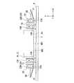
以下、本発明の露光装置について図面を参照しながら説明する。図1は本発明の露光装置の一実施形態を示す概略構成図である。 The exposure apparatus of the present invention will be described below with reference to the drawings. FIG. 1 is a schematic block diagram showing an embodiment of the exposure apparatus of the present invention.
図1において、露光装置EXは、マスクMを支持するマスクステージMSTと、基板Pを支持する基板ステージPSTと、マスクステージMSTに支持されているマスクMを露光光ELで照明する照明光学系ILと、露光光ELで照明されたマスクMのパターン像を基板ステージPSTに支持されている基板Pに投影露光する投影光学系PLと、露光装置EX全体の動作を統括制御する制御装置CONTとを備えている。 In FIG. 1, an exposure apparatus EX includes a mask stage MST that supports a mask M, a substrate stage PST that supports a substrate P, and an illumination optical system IL that illuminates the mask M supported by the mask stage MST with exposure light EL. A projection optical system PL that projects and exposes the pattern image of the mask M illuminated by the exposure light EL onto the substrate P supported by the substrate stage PST, and a control device CONT that controls the overall operation of the exposure apparatus EX. I have.
また、本実施形態の露光装置EXは、露光波長を実質的に短くして解像度を向上するとともに焦点深度を実質的に広くするために液浸法を適用した液浸露光装置であって、基板P上に液体1を供給する液体供給機構10と、基板P上の液体1を回収する液体回収機構20とを備えている。露光装置EXは、少なくともマスクMのパターン像を基板P上に転写している間、液体供給機構10から供給した液体1により投影光学系PLの投影領域AR1を含む基板P上の一部に液浸領域AR2を形成する。具体的には、露光装置EXは、投影光学系PLの先端部の光学素子2と基板Pの表面との間に液体1を満たし、この投影光学系PLと基板Pとの間の液体1及び投影光学系PLを介してマスクMのパターン像を基板P上に投影し、基板Pを露光する。 The exposure apparatus EX of the present embodiment is an immersion exposure apparatus to which an immersion method is applied in order to improve the resolution by substantially shortening the exposure wavelength and substantially increase the depth of focus. A
ここで、本実施形態では、露光装置EXとしてマスクMと基板Pとを走査方向における互いに異なる向き(逆方向)に同期移動しつつマスクMに形成されたパターンを基板Pに露光する走査型露光装置(所謂スキャニングステッパ)を使用する場合を例にして説明する。以下の説明において、投影光学系PLの光軸AXと一致する方向をZ軸方向、Z軸方向に垂直な平面内でマスクMと基板Pとの同期移動方向(走査方向)をX軸方向、Z軸方向及びY軸方向に垂直な方向(非走査方向)をY軸方向とする。また、X軸、Y軸、及びZ軸まわり方向をそれぞれ、θX、θY、及びθZ方向とする。なお、ここでいう「基板」は半導体ウエハ上に感光性材料であるフォトレジストを塗布したものを含み、「マスク」は基板上に縮小投影されるデバイスパターンを形成されたレチクルを含む。 Here, in the present embodiment, as the exposure apparatus EX, scanning exposure is performed in which the pattern formed on the mask M is exposed to the substrate P while the mask M and the substrate P are synchronously moved in different directions (reverse directions) in the scanning direction. A case where an apparatus (so-called scanning stepper) is used will be described as an example. In the following description, the direction that coincides with the optical axis AX of the projection optical system PL is the Z-axis direction, the synchronous movement direction (scanning direction) between the mask M and the substrate P in the plane perpendicular to the Z-axis direction is the X-axis direction, A direction (non-scanning direction) perpendicular to the Z-axis direction and the Y-axis direction is defined as a Y-axis direction. Further, the directions around the X axis, the Y axis, and the Z axis are defined as θX, θY, and θZ directions, respectively. Here, the “substrate” includes a semiconductor wafer coated with a photoresist, which is a photosensitive material, and the “mask” includes a reticle on which a device pattern to be reduced and projected on the substrate is formed.
照明光学系ILはマスクステージMSTに支持されているマスクMを露光光ELで照明するものであり、露光用光源、露光用光源から射出された光束の照度を均一化するオプティカルインテグレータ、オプティカルインテグレータからの露光光ELを集光するコンデンサレンズ、リレーレンズ系、露光光ELによるマスクM上の照明領域をスリット状に設定する可変視野絞り等を有している。マスクM上の所定の照明領域は照明光学系ILにより均一な照度分布の露光光ELで照明される。照明光学系ILから射出される露光光ELとしては、例えば水銀ランプから射出される紫外域の輝線(g線、h線、i線)及びKrFエキシマレーザ光(波長248nm)等の遠紫外光(DUV光)や、ArFエキシマレーザ光(波長193nm)及びF2レーザ光(波長157nm)等の真空紫外光(VUV光)などが用いられる。本実施形態においてはArFエキシマレーザ光が用いられる。The illumination optical system IL illuminates the mask M supported on the mask stage MST with the exposure light EL. A condenser lens for condensing the exposure light EL, a relay lens system, a variable field stop for setting the illumination area on the mask M by the exposure light EL in a slit shape, and the like. A predetermined illumination area on the mask M is illuminated with the exposure light EL having a uniform illuminance distribution by the illumination optical system IL. As the exposure light EL emitted from the illumination optical system IL, for example, far ultraviolet light (g-line, h-line, i-line) and KrF excimer laser light (wavelength 248 nm) emitted from a mercury lamp, DUV light), vacuum ultraviolet light (VUV light) such as ArF excimer laser light (wavelength 193 nm) and F2 laser light (wavelength 157 nm), or the like is used. In this embodiment, ArF excimer laser light is used.
マスクステージMSTはマスクMを支持するものであって、投影光学系PLの光軸AXに垂直な平面内、すなわちXY平面内で2次元移動可能及びθZ方向に微小回転可能である。マスクステージMSTはリニアモータ等のマスクステージ駆動装置MSTDにより駆動される。マスクステージ駆動装置MSTDは制御装置CONTにより制御される。マスクステージMST上には移動鏡50が設けられている。また、移動鏡50に対向する位置にはレーザ干渉計51が設けられている。マスクステージMST上のマスクMの2次元方向の位置、及び回転角はレーザ干渉計51によりリアルタイムで計測され、計測結果は制御装置CONTに出力される。制御装置CONTはレーザ干渉計51の計測結果に基づいてマスクステージ駆動装置MSTDを駆動することでマスクステージMSTに支持されているマスクMの位置決めを行う。 The mask stage MST supports the mask M, and can move two-dimensionally in a plane perpendicular to the optical axis AX of the projection optical system PL, that is, in the XY plane, and can be slightly rotated in the θZ direction. The mask stage MST is driven by a mask stage driving device MSTD such as a linear motor. The mask stage driving device MSTD is controlled by the control device CONT. A
投影光学系PLはマスクMのパターンを所定の投影倍率βで基板Pに投影露光するものであって、基板P側の先端部に設けられた光学素子(レンズ)2を含む複数の光学素子で構成されており、これら光学素子は鏡筒PKで支持されている。本実施形態において、投影光学系PLは、投影倍率βが例えば1/4あるいは1/5の縮小系である。なお、投影光学系PLは等倍系及び拡大系のいずれでもよい。また、本実施形態の投影光学系PLの先端部の光学素子2は鏡筒PKに対して着脱(交換)可能に設けられており、光学素子2には液浸領域AR2の液体1が接触する。 The projection optical system PL projects and exposes the pattern of the mask M onto the substrate P at a predetermined projection magnification β, and includes a plurality of optical elements including an optical element (lens) 2 provided at the front end portion on the substrate P side. These optical elements are supported by a lens barrel PK. In the present embodiment, the projection optical system PL is a reduction system having a projection magnification β of, for example, 1/4 or 1/5. Note that the projection optical system PL may be either an equal magnification system or an enlargement system. The
光学素子2は蛍石で形成されている。蛍石は水との親和性が高いので、光学素子2の液体接触面2aのほぼ全面に液体1を密着させることができる。すなわち、本実施形態においては光学素子2の液体接触面2aとの親和性が高い液体(水)1を供給するようにしているので、光学素子2の液体接触面2aと液体1との密着性が高く、光学素子2と基板Pとの間の光路を液体1で確実に満たすことができる。なお、光学素子2は水との親和性が高い石英であってもよい。また光学素子2の液体接触面2aに親水化(親液化)処理を施して、液体1との親和性をより高めるようにしてもよい。 The
基板ステージPSTは基板Pを支持するものであって、基板Pを基板ホルダを介して保持するZステージ52と、Zステージ52を支持するXYステージ53と、XYステージ53を支持するベース54とを備えている。基板ステージPSTはリニアモータ等の基板ステージ駆動装置PSTDにより駆動される。基板ステージ駆動装置PSTDは制御装置CONTにより制御される。Zステージ52を駆動することにより、Zステージ52に保持されている基板PのZ軸方向における位置(フォーカス位置)、及びθX、θY方向における位置が制御される。また、XYステージ53を駆動することにより、基板PのXY方向における位置(投影光学系PLの像面と実質的に平行な方向の位置)が制御される。
すなわち、Zステージ52は、基板Pのフォーカス位置及び傾斜角を制御して基板Pの表面をオートフォーカス方式、及びオートレベリング方式で投影光学系PLの像面に合わせ込み、XYステージ53は基板PのX軸方向及びY軸方向における位置決めを行う。なお、ZステージとXYステージとを一体的に設けてよいことは言うまでもない。The substrate stage PST supports the substrate P, and includes a
That is, the
基板ステージPST(Zステージ52)上には、基板ステージPSTとともに投影光学系PLに対して移動する移動鏡55が設けられている。また、移動鏡55に対向する位置にはレーザ干渉計56が設けられている。基板ステージPST上の基板Pの2次元方向の位置、及び回転角はレーザ干渉計56によりリアルタイムで計測され、計測結果は制御装置CONTに出力される。制御装置CONTはレーザ干渉計56の計測結果に基づいて基板ステージ駆動装置PSTDを駆動することで基板ステージPSTに支持されている基板Pの位置決めを行う。 On the substrate stage PST (Z stage 52), a
また、基板ステージPST(Zステージ52)上には、基板Pを囲むように補助プレート57が設けられている。補助プレート57は基板ホルダに保持された基板Pの表面とほぼ同じ高さの平面を有している。ここで、基板Pのエッジと補助プレート57との間には0.1〜2mm程度の隙間があるが、液体1の表面張力によりその隙間に液体1が流れ込むことはほとんどなく、基板Pの周縁近傍を露光する場合にも、補助プレート57により投影光学系PLの下に液体1を保持することができる。 An
液体供給機構10は所定の液体1を基板P上に供給するものであって、液体1を供給可能な第1液体供給部11及び第2液体供給部12と、第1液体供給部11に流路を有する供給管11Aを介して接続され、この第1液体供給部11から送出された液体1を基板P上に供給する供給口13Aを有する第1供給部材13と、第2液体供給部12に流路を有する供給管12Aを介して接続され、この第2液体供給部12から送出された液体1を基板P上に供給する供給口14Aを有する第2供給部材14とを備えている。第1、第2供給部材13、14は基板Pの表面に近接して配置されており、基板Pの面方向において互いに異なる位置に設けられている。具体的には、液体供給機構10の第1供給部材13は投影領域AR1に対して走査方向一方側(−X側)に設けられ、第2供給部材14は他方側(+X側)に設けられている。 The
第1、第2液体供給部11、12のそれぞれは、液体1を収容するタンク、及び加圧ポンプ等を備えており、供給管11A、12A及び供給部材13、14のそれぞれを介して基板P上に液体1を供給する。また、第1、第2液体供給部11、12の液体供給動作は制御装置CONTにより制御され、制御装置CONTは第1、第2液体供給部11、12による基板P上に対する単位時間あたりの液体供給量をそれぞれ独立して制御可能である。 Each of the first and second
本実施形態において、液体1には純水が用いられる。純水はArFエキシマレーザ光のみならず、例えば水銀ランプから射出される紫外域の輝線(g線、h線、i線)及びKrFエキシマレーザ光(波長248nm)等の遠紫外光(DUV光)も透過可能である。 In the present embodiment, pure water is used as the
液体回収機構20は基板P上の液体1を回収するものであって、基板Pの表面に近接して配置された回収口22Aを有する回収部材22と、この回収部材22に流路を有する回収管21Aを介して接続された液体回収部21とを備えている。液体回収部21は例えば真空ポンプ等の吸引装置、及び回収した液体1を収容するタンク等を備えており、基板P上の液体1を回収部材22及び回収管21Aを介して回収する。液体回収部21の液体回収動作は制御装置CONTにより制御され、制御装置CONTは液体回収部21による単位時間あたりの液体回収量を制御可能である。 The
また、液体回収機構20の回収部材22の外側には、液体1を捕捉する所定長さの液体トラップ面31が形成されたトラップ部材30が配置されている。 A
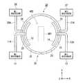
図2は液体供給機構10及び液体回収機構20の概略構成を示す平面図、図3は一部破断して図示した斜視図である。 FIG. 2 is a plan view showing a schematic configuration of the
図2に示すように、投影光学系PLの投影領域AR1はY軸方向(非走査方向)を長手方向とする矩形状に設定されており、液体1が満たされた液浸領域AR2は投影領域AR1を含むように基板P上の一部に形成されている。そして、投影領域AR1の液浸領域AR2を形成するための液体供給機構10の第1供給部材13は投影領域AR1に対して走査方向一方側(−X側)に設けられ、第2供給部材14は他方側(+X側)に設けられている。 As shown in FIG. 2, the projection area AR1 of the projection optical system PL is set in a rectangular shape having the longitudinal direction in the Y-axis direction (non-scanning direction), and the liquid immersion area AR2 filled with the
図2及び図3に示すように、第1、第2供給部材13、14は、第1、第2液体供給部11、12から送出された液体1を流通する内部空間(内部流路)13H、14Hと、内部空間13H、14Hを流通した液体1を基板P上に供給する供給口13A、14Aとをそれぞれ有している。なお、図3には第2液体供給部12は図示されていないが、構造は第1液体供給部11と同じである。第1、第2供給部材13、14の供給口13A、14Aはそれぞれ平面視略円弧状に形成されており、この供給口13A、14AのY軸方向におけるサイズは、少なくとも投影領域AR1のY軸方向におけるサイズより大きくなるように設定されている。そして、平面視略円弧状に形成されている供給口13A、14Aは走査方向(X方向)に関して投影領域AR1を挟むように配置されている。液体供給機構10は、供給口13A、14Aより、投影領域AR1に対して異なる複数の方向に離れた複数の位置から、すなわち、矩形の投影領域AR1の異なる側(この例では、投影領域AR1の両側(+X方向側、−X方向側))から液体1を同時に供給する。 As shown in FIGS. 2 and 3, the first and
液体回収機構20の回収部材22は二重環状部材であって、基板Pの表面に向くように環状に連続的に形成された回収口22Aと、回収口22Aから回収された液体1を流通する環状の内部空間(内部流路)22Hとを有している。液体回収機構20の回収部材22は液体回収機構10の供給部材13、14、及び投影領域AR1を取り囲むように配置されている。そして、回収部材22の内部にはこの内部空間22Hを周方向において複数の空間(分割空間)24に分割する仕切部材(仕切り)23が所定間隔で設けられている。
すなわち、投影領域AR1を取り囲むように連続的に形成された回収口22Aの内部に仕切部材23が設けられた構成となっている。仕切部材23により分割された分割空間24のそれぞれは上下方向で貫通している。そして、回収部材22のうち、回収口22Aを有する下端部は基板Pの表面に近接され、一方、上端部は複数の分割空間24を空間的に集合する集合空間部であるマニホールド部25となっている。そして、このマニホールド部25に回収管21Aの一端部が接続され、他端部が液体回収部21に接続されている。液体回収機構20は、液体回収部21を駆動することにより、回収口22A(回収部材22)及び回収管21Aを介して基板P上の液体1を回収する。すなわち、回収口22Aの設置位置が基板P上の液体1の回収を行う回収位置であり、液体回収機構20は投影領域AR1から離れた回収位置で基板P上の液体1の回収を行うようになっている。ここで、液体回収機構20の回収口22Aは平面視略円環状であって投影領域AR1を取り囲んだ構成となっている。すなわち、回収口22Aは、矩形の投影領域AR1の4つの側(+X方向側、−X方向側、+Y方向側、−Y方向側)、換言すると投影領域AR1に対して直交する4つの方向に離れた4つの位置に存在している。したがって、液体回収機構20は、投影領域AR1を取り囲むように設けられている回収口22Aより、投影領域AR1に対して異なる複数の方向に離れた複数の位置で基板P上の液体1の回収を同時に行うことができる。The
That is, the
そして、液体供給機構10の第1、第2供給部材13、14それぞれの供給口13A、14Aの設置位置、すなわち基板P上に対する液体1の供給位置は、液体回収位置(回収口22Aの位置)と投影領域AR1との間に設けられた構成となっている。つまり、液体供給機構10による液体1の供給は、液体回収機構20の液体回収位置と投影領域AR1との間で行われる。 The installation positions of the
図4は基板Pに近接して配置された第1、第2供給部材13、14、及び回収部材22を示す要部拡大側断面図である。図4に示すように、液体供給機構10の第1、第2供給部材13、14それぞれの内部流路13H、14Hは基板Pの表面に対してほぼ垂直に設けられている。同様に、液体回収機構20の回収部材22の内部流路22H(分割空間24)も、基板Pの表面に対してほぼ垂直に設けられている。そして、第1、第2供給部材13、14による基板Pに対する液体1の供給位置(供給口13A、14Aの設置位置)は、液体回収機構20の液体回収位置(回収口22Aの設置位置)と投影領域AR1との間に設定されている。また、投影光学系PLと第1、第2供給部材13、14のそれぞれとは所定距離だけ離れて設けられているとともに、回収部材22と第1、第2供給部材13、14のそれぞれとも所定距離だけ離れて設けられている。また、本実施形態では、基板Pの表面と供給口13A、14Aとの距離と、基板Pの表面と回収口22Aとの距離と、基板Pの表面と投影光学系PLの下端面との距離とはほぼ同じに設定されている。換言すれば、供給口13A、14A、回収口22A、及び投影光学系PLの下端面それぞれのZ軸方向における位置(高さ)は同じに設定されている。 FIG. 4 is an enlarged side cross-sectional view of a main part showing the first and
そして、第1、第2供給部材13、14の供給口13A、14Aから基板Pに、基板面に対してほぼ垂直方向から供給された液体1は、投影光学系PLの先端部(光学素子2)の下端面と基板Pとの間に濡れ拡がるように供給される。また、投影領域AR1に対して供給部材13、14の外側に流出した液体1は、この供給部材13、14より投影領域AR1に対して外側に配置されている回収部材22の回収口22Aより基板面からほぼ垂直方向に回収(吸引)されるようになっている。 The liquid 1 supplied from the
ここで、液体供給機構10及び液体回収機構20を構成する各部材のうち少なくとも液体1が流通する部材は、例えばポリ四フッ化エチレン等の合成樹脂により形成されている。これにより、液体1に不純物が含まれることを抑制できる。 Here, among the members constituting the
液体回収機構20の回収部材22のうち投影領域AR1に対して外側には、液体回収機構20の回収部材22で回収しきれなかった液体1を捕捉する所定長さの液体トラップ面31が形成されたトラップ部材30が設けられている。トラップ部材30は回収部材22の外側面に取り付けられている。トラップ面31はトラップ部材30のうち基板P側を向く面(すなわち下面)であって、図4に示すように、水平面に対して傾斜している。具体的には、トラップ面31は投影領域AR1(液浸領域AR2)に対して外側に向かうにつれて基板Pの表面に対して離れるように(上に向かうように)傾斜している。トラップ部材30は、例えばステンレス等の金属により形成されている。 A
図2に示すように、トラップ部材30は平面視環状部材であって、回収部材22に嵌合するように回収部材22の外側面に接続されている。そして、トラップ部材30のトラップ面31は投影領域AR1(液浸領域AR2)を取り囲むように配置されており、本実施形態におけるトラップ部材30及びこの下面のトラップ面31は平面視略楕円形状となっている。すなわち、トラップ部材30のトラップ面31は投影光学系PLの光軸AXを基準として、放射方向の長さがその位置に応じて異なるように設けられている。本実施形態では、走査方向(X軸方向)におけるトラップ面31の長さが、非走査方向(Y軸方向)に対して長くなっている。更に具体的には、投影領域AR1のY軸方向中央部に対応する位置におけるトラップ面31の長さが最も長くなっている。 As shown in FIG. 2, the
トラップ面31には、液体1との親和性を高める親液化処理(親水化処理)が施されている。本実施形態において、液体1は水であるため、トラップ面31には水との親和性に応じた表面処理が施されている。なお、基板Pの表面には撥水性(接触角70〜80°程度)のArFエキシマレーザ用の感光材(例えば、東京応化工業株式会社製TARF-P6100)が塗布されており、トラップ面31の液体1に対する液体親和性が基板Pの表面の液体1に対する液体親和性よりも高くなっている。 The
トラップ面31に対する表面処理は液体1の極性に応じて行われる。本実施形態における液体1は極性の大きい水であるため、トラップ面31に対する親水化処理として、例えばアルコールなど極性の大きい分子構造の物質で薄膜を形成することで、このトラップ面31に対して親水性を付与する。あるいは、トラップ面31に対して、例えば処理ガスとして酸素(O2)を用いてプラズマ処理するO2プラズマ処理を施すことによっても親水性を付与することができる。このように、液体1として水を用いる場合にはトラップ面31にOH基など極性の大きい分子構造を持ったものを表面に配置させる処理が望ましい。
ここで、表面処理のための薄膜は液体1に対して非溶解性の材料により形成される。また、親液化処理は、使用する液体1の材料特性に応じてその処理条件を適宜変更される。The surface treatment for the
Here, the thin film for surface treatment is formed of a material that is insoluble in the
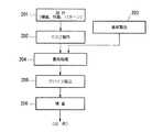
次に、上述した露光装置EXを用いてマスクMのパターン像を基板Pに露光する方法について説明する。 Next, a method for exposing the pattern image of the mask M onto the substrate P using the above-described exposure apparatus EX will be described.
ここで、本実施形態における露光装置EXは、マスクMと基板PとをX軸方向(走査方向)に移動しながらマスクMのパターン像を基板Pに投影露光するものであって、走査露光時には、投影光学系PLの先端部直下の矩形状の投影領域AR1にマスクMの一部のパターン像が投影され、投影光学系PLに対して、マスクMが−X方向(又は+X方向)に速度Vで移動するのに同期して、XYステージ53を介して基板Pが+X方向(又は−X方向)に速度β・V(βは投影倍率)で移動する。そして、図5の平面図に示すように、基板P上には複数のショット領域S1〜S12が設定されており、1つのショット領域への露光終了後に、基板Pのステッピング移動によって次のショット領域が走査開始位置に移動し、以下、ステップ・アンド・スキャン方式で基板Pを移動しながら各ショット領域に対する走査露光処理が順次行われる。なお、本実施形態では、制御装置CONTは、投影光学系PLの光軸AXが図5の破線矢印58に沿って進むようにレーザ干渉計56の出力をモニタしつつXYステージ53を移動するものとする。 Here, the exposure apparatus EX in the present embodiment projects and exposes the pattern image of the mask M onto the substrate P while moving the mask M and the substrate P in the X-axis direction (scanning direction). Then, a part of the pattern image of the mask M is projected onto the rectangular projection area AR1 directly under the tip of the projection optical system PL, and the mask M moves in the −X direction (or + X direction) with respect to the projection optical system PL. In synchronization with the movement at V, the substrate P moves through the
まず、マスクMがマスクステージMSTにロードされるとともに、基板Pが基板ステージPSTにロードされる(図1参照)。次いで、走査露光処理を行うに際し、制御装置CONTは液体供給機構10を駆動し、基板P上に対する液体供給動作を開始する。液浸領域AR2を形成するために液体供給機構10の第1、第2液体供給部11、12のそれぞれから供給された液体1は、供給管11A、12Aを流通した後、第1、第2供給部材13、14を介して基板P上に供給され、投影光学系PLと基板Pとの間に液浸領域AR2を形成する。ここで、図4に示すように、供給管11A、12Aを流通した液体1は供給部材13、14の内部流路13H、14Hの幅方向に拡がり、供給口13A、14Aより基板P上の広い範囲に供給される。このとき、供給口13A、14Aは投影領域AR1のX軸方向(走査方向)両側に配置されており、制御装置CONTは、液体供給機構10の供給口13A、14Aより投影領域AR1の両側から基板P上への液体1の供給を同時に行う。 First, the mask M is loaded on the mask stage MST, and the substrate P is loaded on the substrate stage PST (see FIG. 1). Next, when performing the scanning exposure process, the control device CONT drives the
液体供給機構10は、投影領域AR1の両側に設けられている供給口13A、14Aより、すなわち、投影領域AR1に対して異なる複数の方向(+X方向、−X方向)に離れた複数の位置から液体1を同時に供給する。これにより、供給口13A、14Aから基板P上に供給された液体1は液浸領域AR2を少なくとも投影領域AR1より広い範囲で形成する。 The
本実施形態において、投影領域AR1の走査方向両側から基板Pに対して液体1を供給する際、制御装置CONTは、液体供給機構10の第1、第2液体供給部11、12の液体供給動作を制御し、走査方向に関して、投影領域AR1の手前から供給する単位時間あたりの液体供給量を、その反対側で供給する液体供給量よりも多く設定する。例えば、基板Pを+X方向に移動しつつ露光処理する場合、制御装置CONTは、投影領域AR1に対して−X側(すなわち供給口13A)からの液体量を、+X側(すなわち供給口14A)からの液体量より多くし、一方、基板Pを−X方向に移動しつつ露光処理する場合、投影領域AR1に対して+X側からの液体量を、−X側からの液体量より多くする。 In this embodiment, when supplying the
また、制御装置CONTは、液体回収機構20の液体回収部21を駆動し、液体供給機構10による液体1の供給動作と並行して、基板P上の液体回収動作を行う。これにより、図4に示すように、供給口13A、14Aより投影領域AR1に対して外側に流れる基板P上の液体1は、回収口22Aより回収される。回収口22Aから回収された液体1は仕切部材23により仕切られた分割空間24のそれぞれを流通した後、マニホールド部25に集合する。マニホールド部25に集合した液体1は回収管21Aを通って液体回収部21に回収される。このように、本実施形態では、1つの液体回収部21に対して複数の分割空間24が接続されている構造を備えている。そして、液体回収機構20は、投影領域AR1を取り囲むように設けられている回収口22Aより、投影領域AR1に対して異なる複数の方向に離れた複数の位置、すなわち、矩形の投影領域AR1の4つの側(+X方向側、−X方向側、+Y方向側、−Y方向側)から基板P上の液体1の回収を同時に行う。 Further, the control device CONT drives the
制御装置CONTは、液体供給機構10及び液体回収機構20により基板Pの表面に対する液体1の供給と並行して基板P上の液体1の回収を行いつつ、基板Pを支持する基板ステージPSTをX軸方向(走査方向)に移動しながら、マスクMのパターン像を投影光学系PLと基板Pとの間の液体1及び投影光学系PLを介して基板P上に投影露光する。
このとき、液体供給機構10は走査方向に関して投影領域AR1の両側から供給口13A、14Aを介して液体1の供給を同時に行っているので、液浸領域AR2は均一且つ良好に形成されている。また、液体回収機構20は、投影領域AR1を囲む回収部材22の回収口22Aを介して投影領域AR1の走査方向両側を含む投影領域AR1周囲の複数の位置において液体1の回収を同時に行っているため、液体1の基板P周囲への流出や飛散を防止している。なお、本実施形態においては、基板P表面の感光材との親和性が低い純水を液体1として供給するようにしているので、液体回収機構20による回収を円滑に行うことができる。The control device CONT performs the recovery of the
At this time, since the
図6(a)は、基板Pを+X方向に移動しながら基板P上に設定された第1のショット領域(例えば図5のS1、S3など)を露光処理する際の液体1の挙動を示す模式図である。図6(a)において、投影光学系PLと基板Pとの間の空間に対して供給口13A、14Aから液体1が同時に供給され、これにより投影領域AR1を含むように液浸領域AR2が形成される。ここで、投影領域AR1に対して−X側に設けられている供給口13Aから供給される液体1の単位時間あたりの液体量が、+X側に設けられている供給口14Aから供給される液体1の単位時間あたりの液体量より多く設定されているため、供給口13Aから供給された液体1は+X方向に移動する基板Pに引っ張られるようにして、投影光学系PLと基板Pとの間の空間に円滑に配置される。また、供給口13A、14Aより外側に流出しようとする液体1は回収口22Aより回収され、基板P周囲に流出したりする不都合の発生が抑えられている。 FIG. 6A shows the behavior of the
ここで、基板Pが+X方向に移動することにより、投影領域AR1に対して+X側に移動する液体量が増し、+X側に液体回収位置を設けている回収口22Aが液体1を全て回収できない場合がある。ところが、図6(a)に示すように、+X側の回収口22Aで回収しきれなかった液体1はこの液体回収位置より+X側に設けられているトラップ部材30のトラップ面31で捕捉されるため、基板Pの周囲等に流出したり飛散したりすることがない。ここで、トラップ面31は液体1に対して親液化処理されており、しかも基板Pの表面より高い液体親和性を有しているので、回収口22Aの液体回収位置より外側に流出しようとする液体1は、基板P側に引っ張られずにトラップ面31側に引っ張られる。
これにより、基板P上に液体1が残存する等の不都合の発生が抑えられている。Here, when the substrate P moves in the + X direction, the amount of liquid that moves to the + X side with respect to the projection area AR1 increases, and the
Thereby, the occurrence of inconvenience such as the
ここで、トラップ面31は投影領域AR1を含む液浸領域AR2を基準として外側に向かうにつれて上方向に傾斜しているため、液体1の外部への流出をより効果的に防止できる。つまり、上方向に傾斜していることにより、基板Pと投影光学系PLとの間の第1の体積(基板Pの単位面積に対応する体積)に対して、基板Pとトラップ面31との間の第2の体積のほうが大きくなるため、流出しようとする液体1は第2の体積部分に円滑に保持される。また、上方向に傾斜していることにより、外側に流出しようとする流体エネルギーはトラップ面31に沿って上方向に移動することで位置エネルギーに変換され、これにより液体1の外側への流出を効果的に防止できる。 Here, since the
また、+X側に設けられている供給口14Aから供給される液体量は、−X側に設けられている供給口13Aから供給される液体量に対して少なく設定されている。すなわち、+X側の回収口22Aに対して供給口13Aより近い位置にある供給口14Aからの液体供給量が少なく設定されているので、+X側に移動する基板Pに液体1が引っ張られても、基板Pの+X側から外部に流出しようとする液体量が抑えられている。 The amount of liquid supplied from the
第1のショット領域の露光処理が終了したら、制御装置CONTは、投影光学系PLの投影領域AR1を前記第1のショット領域とは別の第2のショット領域に配置するために、基板Pをステッピング移動する。具体的には、例えばショット領域S1に対する走査露光処理終了後、ショット領域S2に対して走査露光処理するために、制御装置CONTは基板P上の2つのショット領域S1、S2間でY軸方向にステッピング移動する。このとき、液体供給機構10は、基板P上の2つのショット領域間のステッピング移動中における液体1の供給量を、ショット領域の露光中における供給量に対して異ならせる。具体的には、制御装置CONTは、ステッピング移動中での液体供給機構10からの基板P上に対する単位時間あたりの液体供給量を、ショット領域の走査露光中の液体供給量より少なくする。これにより、露光処理に寄与しないステッピング移動中での基板Pに対する液体供給量が抑えられ、露光処理全体(基板Pが基板ステージPSTにロードされて全ショット領域S1〜S12に対する露光処理が終了して基板ステージPSTからアンロードされるまで)における液体使用量を抑えることができる。このように、制御装置CONTは、露光処理実行動作の一部を構成する基板Pの移動動作(ステッピング移動又は走査移動)に応じて、第1、第2液体供給部11、12それぞれの単位時間あたりの液体供給量を変える。 When the exposure process for the first shot area is completed, the control device CONT places the substrate P in order to place the projection area AR1 of the projection optical system PL in a second shot area different from the first shot area. Move stepping. Specifically, for example, after the scanning exposure process for the shot area S1 is completed, the control device CONT performs the scanning exposure process for the shot area S2 between the two shot areas S1 and S2 on the substrate P in the Y-axis direction. Move stepping. At this time, the
ここで、液体供給機構10は、基板Pのステッピング移動中において液体1の単位時間あたりの供給量を低減させるが、液体1の供給動作を維持(継続)する。つまり、液体供給機構10は、ショット領域が変わることにより走査方向が変わったり、あるいはステッピング移動時においても、供給口13A、14Aからの液体供給動作を維持(継続)する。このように、液体供給機構10は、基板P上の複数のショット領域を順次露光するときに、複数の位置に設けられた供給口13A、14Aから液体1を供給し続け、走査方向に応じて液体供給位置を変えたり、ステッピング移動時に液体供給位置を変えたりしない。
換言すれば、液体供給機構10は、1つの基板Pに関する一連の露光処理動作が終了するまで(基板Pが基板ステージPSTにロードされて全ショット領域S1〜S12に対する露光処理が終了して基板ステージPSTからアンロードされるまで)、複数の位置から液体1を供給し続ける。これにより、液体1の供給及び停止に起因する液体の振動(ウォーターハンマー現象)の発生を防止することができる。Here, the
In other words, the
図6(b)は、基板Pを−X方向に移動しながら基板P上に設定された第2のショット領域(例えば図5のS2、S4など)を露光処理する際の液体1の挙動を示す模式図である。図6(b)において、投影光学系PLと基板Pとの間の空間に対して供給口13A、14Aから液体1が供給され、これにより投影領域AR1を含むように液浸領域AR2が形成される。ここで、投影領域AR1に対して+X側に設けられている供給口14Aから供給される液体1の単位時間あたりの液体量が、−X側に設けられている供給口13Aから供給される液体1の単位時間あたりの液体量より多く設定されているため、供給口14Aから供給された液体1は−X方向に移動する基板Pに引っ張られるようにして、投影光学系PLと基板Pとの間の空間に円滑に配置される。このように、制御装置CONTは、露光処理実行動作の一部を構成する基板Pの移動方向(移動動作)に応じて、第1、第2液体供給部11、12それぞれの単位時間あたりの液体供給量を変える。また、供給口13A、14Aより外側に流出しようとする液体1は回収口22Aより回収され、基板P周囲に流出したりする不都合の発生を抑えられている。 FIG. 6B shows the behavior of the
ここで、基板Pが−X方向に移動することにより、+X側のトラップ面31に捕捉されている液体1はトラップ面31に沿って下降し、液体回収機構20の回収口22Aより回収される。これにより、液体1の残存や外部への流出を確実に防止することができる。そして、基板Pの−X側への移動に伴って−X側に移動する液体量が増し、これにより−X側の回収口22Aで液体1を全て回収しきれなくても、図6(b)に示すように、この液体回収位置より−X側に設けられているトラップ部材30のトラップ面31で液体1が捕捉される。 Here, as the substrate P moves in the −X direction, the
なお、ここでは、トラップ面31は投影領域AR1に対して外側に向かうにつれて上方向に傾斜するように形成されているが、水平(0度)であってもよい。一方、トラップ面31が下方向に傾斜していると、外側に流出しようとする流体エネルギーは位置エネルギーに変換されず、しかも逆方向に基板Pが移動する際にも流体1はトラップ面31に沿って下降するように回収口22Aまで移動しないため、液体1を回収口22Aで円滑に回収することができない。したがって、トラップ面31は水平面(0度)または上方向への傾斜面であることが好ましい。 Here, the
なお、基板P上に対する単位時間あたりの液体供給量が多い場合や、走査速度が高速である場合、外側に流出しようとする液体量も多くなるので、トラップ面31の傾斜角度はこれら液体供給量及び走査速度に応じて最適角度に設定されている。つまり、液体供給量が多い場合や走査速度が高速である場合には、トラップ面31の傾斜角度は大きく設定される。一方、トラップ面31の傾斜角度が大きすぎると、トラップ面31で液体1を捕捉(保持)しきれなくなる場合がある。ここで、親液化処理による親液性を強くすることでトラップ面31の液体保持力が大きくなるので、傾斜角度を大きくする場合、親液化処理の処理条件を変更してトラップ面31に対して最適な親液性を付与することにより、傾斜角度を大きくしても液体1を保持することができる。そこで、トラップ面31の傾斜角度は、液体供給量、走査速度、及び液体の材料特性(トラップ面の液体親和性)等の各パラメータに基づいて、最適角度に設定される。 Note that when the amount of liquid supply per unit time on the substrate P is large or when the scanning speed is high, the amount of liquid that tends to flow outward increases, so the inclination angle of the trapping
ところで、本実施形態の回収部材22は、円環状に連続的に形成された回収口22Aと、回収口22Aの内部に設けられた仕切部材23と、この仕切部材23で分割された複数の分割空間24とを有する構成であって、複数の分割空間24を集合するマニホールド部25に回収管21Aを介して液体回収部21が接続されている構成である。これにより、真空ポンプ等を含んで構成される液体回収部21は1つ設ければいいため、装置構成を簡略化できる。ここで、回収部材22の周方向の各位置のそれぞれにおいて液体1を回収するための吸引負荷が異なる状態が発生し、これにより液体回収部21の吸引力が低下し、回収動作を円滑に行うことができなくなる場合がある。しかしながら、仕切部材23を設けたことにより回収動作を円滑に行うことができる。つまり、例えば、液体1の挙動に起因して、回収部材22のうち+X側の回収口22Aでは液体1のみが回収(吸引)されているのに対し、−X側の回収口22Aでは空気を含んで(空気をかみこんで)吸引する状態が発生する場合がある。この場合、−X側の回収口22Aにおける空気かみこみ領域が拡がり、本実施形態のように一系統の液体回収部21で液体1を回収する場合、かみこんだ空気により液体回収部21を構成する真空ポンプの吸引力が低下する不都合が生じる場合がある。ところが、連続的に形成された回収口22Aの内部(内部空間22H)に仕切部材23を設けて互いに独立した分割空間24を設けたことにより、空気をかみこむ領域に対して液体1のみを吸引する領域を空間的に分離できるので、空気かみこみ領域が拡がったりかみこんだ空気により液体回収部21の吸引力が低下するといった不都合の発生を防止でき、これにより液体回収部21が一系統であっても液体回収機構20は液体1を円滑に回収することができる。 By the way, the
以上説明したように、液浸領域AR2を形成するために、投影領域AR1に対して異なる複数の方向に離れた複数の位置で(投影領域AR1の互いに異なる複数の側から)基板P上の液体1の供給を同時に行う液体供給機構10を設けたので、基板Pが走査方向(±X方向)及びステッピング方向(±Y方向)を含む複数の方向に移動する場合であっても、投影光学系PLと基板Pとの間に液浸領域AR2を常に円滑且つ良好に形成することができる。したがって、高い解像度及び広い焦点深度のもとで露光処理を行うことができる。 As described above, in order to form the liquid immersion area AR2, the liquid on the substrate P at a plurality of positions separated from the projection area AR1 in a plurality of different directions (from a plurality of different sides of the projection area AR1). Since the
基板P上の複数のショット領域のそれぞれを順次露光処理する際に、液体供給機構10により複数の位置から液体1を供給し続けるようにしたので、液体1の供給及び停止に伴う液体振動(ウェーターハンマー現象)の発生を防止することができ、これにより転写されるパターン劣化を防止することができる。 Since the
また、液体供給機構10は、供給口13A、14Aより、投影領域AR1の走査方向両側から液体1を供給するようにしたので、供給された液体1は走査方向に移動する基板Pに引っ張られるようにして投影領域AR1に濡れ拡がるため、液浸領域AR2は投影領域AR1を含むように円滑に形成される。そして、本実施形態では、液体供給機構10は、走査方向に関して、投影領域AR1の手前から供給する液体量を、その反対側で供給する液体量よりも多くするので、基板P上に供給された液体1は、移動する基板Pに引っ張られるようにして基板Pの移動方向に沿って流れ、投影光学系PLと基板Pとの間の空間に引き込まれるようにして円滑に配置される。したがって、液体供給機構10から供給された液体1は、その供給エネルギーが小さくても投影光学系PLと基板Pとの間に円滑に配置され、液浸領域AR2を良好に形成することができる。そして、走査方向に応じて供給口13A、14Aそれぞれから供給する液体量を変更することで液体1の流れる方向を切り替えることができ、これにより+X方向、又は−X方向のどちらの方向に基板Pを走査する場合にも、投影光学系PLと基板Pとの間に液浸領域AR2を円滑に形成することができ、高い解像度及び広い焦点深度を得ることができる。 Further, since the
また、液体回収機構20の回収部材22は、投影領域AR1及び供給部材13、14を囲むように円環状に形成されており、投影領域AR1に対して異なる複数の方向に離れた複数の位置で(投影領域AR1の異なる複数の側から)基板P上の液体1の回収を同時に行うため、基板P外側への液体1の流出や飛散等といった不都合の発生を確実に防ぐことができる。すなわち、液体回収機構20は、1つの基板Pに関する一連の露光処理動作が終了するまで(基板P上の全ショット領域S1〜S12に対する露光処理が終了して、液浸領域AR2を形成していた液体1の回収が完了するまで)、投影領域AR1を取り囲むように形成されている回収口22Aから回収動作を継続的に行なっているので、基板Pの一連の露光処理動作中に液体1がいずれの方向に濡れ拡がっても、液体1を良好に回収することができる。また、基板Pに関する一連の露光処理動作中に、回収口22からの液体の吸引を停止させることもないので、それに伴う振動を影響も抑えることができる。 The
また、液体回収機構20で回収しきれなかった液体1を捕捉するトラップ部材30を設けたことにより、基板P外側への液体1の流出や飛散等の不都合の発生を防止できる。そして、本実施形態において、トラップ面31は、液体1が基板P外側に最も流出しやすい走査方向(X軸方向)に沿う方向を長手方向とする平面視楕円形状に形成されているため、液体1の外部への流出を確実に防止できる。また、トラップ面31には液体1との親和性を高める親液化処理が施されているので、流出しようとする液体1を良好に捕捉することができる。更に、トラップ面31の液体親和性は、基板P表面の液体親和性よりも高くなるように表面処理されているので、外部に流出しようとする液体1は基板Pに付着せずにトラップ面31に捕捉されるため、基板Pの表面に液体1が残存するといった不都合の発生を防止できる。また、トラップ面31は投影領域AR1に対して外側に向かうにつれて上方向に傾斜しているので、外部に流出しようとする液体1を良好に捕捉でき、しかも、基板Pの走査方向が逆方向になった際、捕捉されている液体1はトラップ面31を下方に伝わるため、このトラップ面31に接続する回収口22Aで良好に回収される。 In addition, by providing the
また、液体供給機構10からは、投影光学系PLの先端の液体接触面2aとの親和性が、基板P表面に塗布された感光材との親和性よりも高い、液体(水)1を液浸露光用に供給するようにしているので、投影光学系PLと基板Pとの間の光路を液体1で確実に満たすことができるとともに、基板(P)上に供給された液体(1)が円滑に回収され、液体1の流出や飛散等の不都合を防止できる。 Further, from the
なお、本実施形態では投影領域AR1の走査方向両側から液体1を供給する際、走査方向に関して手前から供給する液体量をその反対側で供給する液体量よりも多くしているが、投影領域AR1の両側から供給する液体1を同量にしてもよい。この場合も、走査方向を切り替える際にも液体1の供給量変動が生じないため、ウォーターハンマー現象の発生をより確実に防止できる。一方、液体1を供給し続けながら、走査方向に応じて投影領域AR1の走査方向両側から供給する液体量を変化させることにより、ウォーターハンマー現象の発生を抑えつつ液体1の使用量を抑えることができる。 In the present embodiment, when the
なお、本実施形態では、1枚の基板Pに対する露光処理動作中は供給口13A、14Aからの液体1の供給をし続ける構成であるが、途中で停止してもよい。例えば、基板Pを+X側に走査移動する際には供給口14Aからの液体供給を停止して供給口13Aのみから液体1を供給し、基板Pを−X側に走査移動する際には供給口13Aからの液体供給を停止して供給口14Aのみから液体1を供給する構成であってもよい。更には、基板Pのステッピング移動時には、液体供給機構10は基板Pに対する液体1の供給を停止する構成でもよい。この場合、走査露光を開始するに際し、液体1の供給を所定時間行って液体振動がおさまるのを待ってから走査露光すればよい。このような構成とすることにより液体1の使用量を抑えることができる。一方、液体1を供給し続けることにより、液体振動がおさまるまでの待ち時間を設定する必要がないため、スループットを向上できる。 In the present embodiment, the
本実施形態では、液体供給機構10の供給口13A、14Aは投影領域AR1に対して走査方向両側に設けられている構成であるが、例えば投影領域AR1の周りを全て囲むように、すなわち投影領域AR1の非走査方向両側にも供給口(供給部材)を設けるようにしてもよい。そして、投影領域AR1を囲むように設けられた供給口のそれぞれから基板P上に液体1を供給するようにしてもよい。ここで、投影領域AR1に対して走査方向両側のそれぞれと、非走査方向両側のそれぞれとに供給口を設けた際、すなわち、投影領域AR1を囲むように互いに独立した4つの供給口を設けた際、基板Pを走査方向に移動しつつ露光処理する際には、4つの供給口の全てから液体1を供給してもよいし、走査方向両側に設けられた供給口のみから液体1を供給し、非走査方向両側に設けられた供給口からの液体供給を停止(あるいは少量供給)してもよい。そして、非走査方向に基板Pを移動するときに、非走査方向両側に設けられた供給口から液体を供給するようにしてもよい。あるいは、投影領域AR1を囲むように環状の供給部材を設け、この供給部材を介して基板P上に液体1を供給する構成であってもよい。この場合、液体1を供給部材に送出する液体供給部は1つでよいため、装置構成を簡略化できる。一方、上記実施形態のように、投影領域AR1に対して走査方向両側に供給口13A、14Aがあれば投影領域AR1を十分に液浸領域AR2にすることができ、液体1の使用量を抑えることができる。 In the present embodiment, the
また本実施形態では、液体供給機構10の供給口13A、14Aは投影領域AR1に対して走査方向両側に設けられている構成であるが、投影光学系PLと基板Pとの間の露光光の露光が液体1で十分に満たされる場合には、投影領域AR1の近くに配置された1箇所の供給口から液体供給をするようにしてもよい。この場合も、1枚の基板P上の全ショットの露光が終了するまで、その1箇所の供給口から液体を供給し続けることによって、ウォーターハンマー現象の発生を抑えつつ液体1の使用量を抑えることができる。 In the present embodiment, the
なお、上記実施形態では、第1、第2供給部材13、14と回収部材22とは離れているが、第1、第2供給部材13、14と回収部材22とは接続されていてもよいし、第1、第2供給部材13、14と回収部材22との間にこれらを接続する接続部材を設けてもよい。また、上記実施形態では、供給部材13、14の内部流路13H、14Hや回収部材22の内部流路22Hは基板Pの表面に対して垂直であるように説明したが、傾斜していてもよい。例えば、供給部材13、14の内部流路13H、14H(あるいは供給口13A、14A)を投影領域AR1側に向くように設けてもよい。更に、供給口13A、14Aと回収部材22の回収口22Aとの基板Pの表面に対する距離(高さ)を異なるように設けてもよい。 In the above embodiment, the first and
なお、供給部材13、14を含む液体供給機構10、及び回収部材22を含む液体回収機構20のそれぞれは、投影光学系PL及びこの投影光学系PLを支持する支持部材以外の支持部材で支持されることが好ましい。これにより、液体回収機構10や液体回収機構20で発生した振動が、投影光学系PLに伝達することを防ぐことができる。また逆に、投影光学系PLと供給部材13、14とを隙間無く接触させることにより、液体1への大気の混入を防ぐ効果も期待できる。 Each of the
以下、本発明の他の実施形態について説明する。ここで、以下の説明において、上述した実施形態と同一又は同等の構成部分については同一の符号を付し、その説明を簡略もしくは省略する。 Hereinafter, other embodiments of the present invention will be described. Here, in the following description, the same or equivalent components as those in the above-described embodiment are denoted by the same reference numerals, and the description thereof is simplified or omitted.
上記実施形態に係る液体回収機構20は、1つの液体回収部21と、この液体回収部21に回収管21Aを介して接続され、円環状に連続的に形成された回収口22Aを有する回収部材22とを備えた構成であるが、複数の液体回収部を設けてもよい。これにより回収口22Aの各回収位置での回収力のばらつきを抑えることが可能となる。また、制御装置CONTはこの複数の液体回収部のそれぞれの回収力を液体回収位置に応じて異ならせるようにしてもよい。このことを図7を参照しながら説明する。 The
図7は、本発明の他の実施形態を示す図であって、液体回収機構20の他の例を示す平面模式図である。図7において、液体回収機構20は、第1液体回収部26と、第2液体回収部27と、この第1液体回収部26に回収管26Aを介して接続された第1回収部材28と、第2液体回収部27に回収管27Aを介して接続された第2回収部材29とを備えている。第1、第2回収部材28、29のそれぞれは平面視略円弧状に形成されており、第1回収部材28は投影領域AR1の−X側に配置され、一方、第2回収部材29は投影領域AR1の+X側に配置されている。なお、第1、第2回収部材28、29は、上記実施形態同様、基板P側を向く回収口と、その内部に設けられた仕切部材とを備えている。また、第1、第2液体回収部26、27の回収動作は制御装置CONTによりそれぞれ独立して行われる。 FIG. 7 is a diagram illustrating another embodiment of the present invention, and is a schematic plan view illustrating another example of the
基板P上のショット領域を走査露光するに際し、制御装置CONTは液体供給機構10より液体1を基板P上に供給するとともに、液体回収機構20のうち第1、第2液体回収部26、27のそれぞれを駆動し、基板P上の液体1を回収する。ここで、制御装置CONTは、液体回収機構20の液体回収力を、液体回収位置に応じて異なるように制御する。具体的には、制御装置CONTは、走査方向に関して、投影領域AR1の手前での単位時間あたりの液体回収量(回収力)を、その反対側での液体回収量よりも少なく設定する。すなわち、走査方向前方側(液体1が流れる下流側)での液体回収力を多くする。具体的には、基板Pが+X方向に移動しているときには、投影領域AR1に対して+X側に設けられた第2回収部材29(第2液体回収部27)による回収力を、−X側に設けられた第1回収部材28(第1液体回収部26)による回収力より大きくする。これにより、外部への流体1の流出を防ぎつつ基板P上の液体回収動作を円滑に行うことができる。 When performing scanning exposure on the shot area on the substrate P, the control device CONT supplies the liquid 1 from the
なお、上記実施形態では、第1、第2液体回収部26、27による液体回収動作を同時に行う構成であるが、別々に行う構成であってもよい。例えば、基板Pが+X方向に移動しているときには、投影領域AR1に対して+X側に設けられた第2回収部材29(第2液体回収部27)による液体回収動作のみを行い、第1回収部材28(第1液体回収部26)による液体回収動作を停止する構成であってもよい。この場合、液体1は主に+X側に流れるため、第2液体回収部27の回収動作のみによっても液体1を回収できる。 In the above-described embodiment, the liquid recovery operation by the first and second
また、上記各実施形態では、液体回収機構20の回収部材は投影領域AR1の全部を囲むように配置されているが、投影領域AR1の走査方向両側のみにある構成であってもよい。 In each of the above embodiments, the recovery member of the
また、上記各実施形態では、液体回収機構20の回収部材は投影領域AR1を取り囲むように連続的に形成されているが、図8に示すように、複数の回収部材22Dを断続的に配置する構成であってもよい。同様に、液体供給機構10に関しても複数の供給部材13D、14Dを断続的に配置する構成であってもよい。この場合も、投影領域AR1を取り囲むように形成された回収口で回収動作を継続的に行なっているので、液体1がいずれの方向に濡れ拡がっても、液体1を良好に回収することができる。 In each of the above embodiments, the recovery member of the
また、液体回収機構20の回収部材を複数設けた場合等において、液体回収機構20は、投影領域AR1に対して走査方向に離れた位置での液体回収力(単位時間あたりの液体回収量)を、それとは別の位置、具体的には非走査方向に離れた位置での液体回収力よりも大きくすることにより、走査露光する際、基板P上の液体1を円滑に回収することができる。 Further, when a plurality of recovery members of the
また、仕切部材23により分割された分割空間24のそれぞれに対して真空ポンプ等を有する複数の液体回収部を回収管を介してそれぞれ接続し、これら複数の液体回収部の回収動作を個別に制御することで、液体回収位置に応じて回収力を異ならせるようにしてもよい。なお、分割空間24のそれぞれに個別に液体回収部を接続せず、1つの液体回収部と複数の分割空間24のそれぞれとを複数の回収管で接続し、これら回収管のそれぞれに弁を設け、弁の開度を調整することで、液体回収位置に応じて回収力を異ならせるようにしてもよい。更には、前記複数の回収管それぞれの長さを変えることで、圧力損失により各分割空間24での回収力を異ならせることも可能である。 In addition, a plurality of liquid recovery units having a vacuum pump or the like are connected to each of the divided
なお、上記各実施形態では、液体供給機構10の供給部材は平面視略円弧状であるが、図9に示すように、直線状であってもよい。ここで、図9に示す平面視直線状の供給部材13、14は、投影領域AR1の走査方向両側にそれぞれ設けられている。同様に、液体回収機構20の回収部材22も円環状に限らず、図9に示すように矩形状であってもよい。 In each of the above embodiments, the supply member of the
図10(a)に示すように、液体供給機構10の供給部材13(14)の内部流路13H(14H)に多孔質体40を設けてもよい。あるいは図10(b)に示すように、仕切部材41を設けてスリット状の流路を形成してもよい。こうすることにより、供給部材13(14)から基板P上に供給される液体1を整流でき、基板P上で乱流が発生したり液体が振動したりする不都合の発生を抑えることができる。 As shown in FIG. 10A, a
上記各実施形態では、トラップ部材30(トラップ面31)は平面視楕円形状であるように説明したが、真円形状、あるいは矩形状であってもよい。一方、液体1が流出しやすいのは投影領域AR1の走査方向両側であるため、上記実施形態のように、トラップ部材30を楕円形状にすることにより、流出しようとする液体1を良好に捕捉できる。また、上記実施形態では、トラップ部材30(トラップ面31)は楕円形状であって回収部材22の液体回収位置の外側全部に回収部材22を取り囲むように設けられている構成であるが、例えば投影領域AR1の走査方向両側のみに設け、投影領域AR1に対して非走査方向に離れた位置には設けない構成とすることができる。液体1が流出しやすいのは走査方向両側であるため、投影領域AR1の走査方向両側にトラップ部材30を設けるだけでも、流出しようとする液体1を良好に捕捉できる。また、トラップ面31の傾斜角度はその位置に応じて異なるように設定されていてもよい。例えば、トラップ面31のうち投影領域AR1の走査方向両側付近の傾斜角度を他の部分より大きくするようにしてもよい。また、トラップ面31はフラット面である必要は無く、例えば複数の平面を組み合わせた形状であってもよい。 In each of the above embodiments, the trap member 30 (trap surface 31) has been described as having an elliptical shape in plan view, but may be a perfect circle or a rectangle. On the other hand, since the
図11はトラップ部材30のトラップ面31の他の実施形態を示す図である。図11に示すように、トラップ面31は曲面状であってもよい。具体的には、図11に示すように、トラップ面31は断面視例えば2次曲線状あるいは円弧状であってもよい。ここで、トラップ面31は基板P側に膨らむ曲面であることが好ましい。このような形状であっても、液体1を良好に捕捉することができる。 FIG. 11 is a view showing another embodiment of the
あるいは、図12に示すように、トラップ面31に対して表面積拡大処理、具体的には粗面処理を施してもよい。粗面処理することによりトラップ面31の表面積が拡大し、液体1をより一層良好に捕捉可能となる。なお、粗面処理はトラップ面31の全面にする必要は無く、トラップ面31のうち、例えば走査方向に沿った一部の領域のみに粗面処理を施す構成であってもよい。 Alternatively, as shown in FIG. 12, the
図13に示すように、トラップ部材30を複数のフィン部材32により構成してもよい。図13において、フィン部材32は側面視略三角形状であって、基板Pに対向する辺(下辺)は、投影領域AR1に対して外側に向かうにつれて上方向に傾斜している。そして、これら複数のフィン部材32は、回収部材22の外側面に、その長手方向を外側に向けるようにして放射状に取り付けられている。ここで、複数のフィン部材32どうしは離間しており、各フィン部材32間には空間部33が形成されている。回収部材22で回収しきれなかった液体1は、フィン部材32の間の空間部33に表面張力で捕捉されることにより、液体1の基板P外部への流出が防止される。 As shown in FIG. 13, the
なお、複数のフィン部材32は等間隔で設けられてもよいし、不等間隔であってもよい。例えば、走査方向に沿う位置に設けられるフィン部材32の間隔を、非走査方向に沿う位置に設けられるフィン部材32の間隔より小さく設定してもよい。また、複数のフィン部材32それぞれの長さ(放射方向のサイズ)は同じでもよいし、走査方向に沿う位置に設けられるフィン部材32の長さがそれ以外の位置に設けられるフィン部材32より長くてもよい。また、トラップ部材30のうち、一部の領域をフィン部材により構成し残りの領域をトラップ面により構成することもできる。更には、図4等を参照して説明したトラップ面31にフィン部材32を取り付ける構成であってもよい。なお、フィン部材32の表面に対しても、液体1との親和性を高める親液化処理を施しておくことが好ましい。 Note that the plurality of
上記各実施形態において、トラップ面31(あるいはフィン部材32)に対して親液化処理を施す場合、このトラップ面31の親液性に分布を持たせるようにしてもよい。換言すれば、表面処理する面上の複数の領域についての液体の接触角がそれぞれ異なる値となるように表面処理を行うことができる。例えば、トラップ面31のうち投影領域AR1に対して外側の一部の領域の親液性を内側の領域に対して低下するようにしてもよい。更に、トラップ面31の全部を親液化処理する必要はなく、例えば走査方向に沿う一部の領域のみを親液化処理する構成であってもよい。 In each of the above embodiments, when the lyophilic process is performed on the trap surface 31 (or the fin member 32), the lyophilicity of the
なお、上記実施形態では、トラップ面31に対して親液化処理を施すように説明したが、液体供給機構10や液体回収機構20のうち液体1が流れる流路の表面に対しても親液化処理を施すことができる。特に、液体回収機構20の回収部材22に親液化処理を施しておくことにより、液体回収を円滑に行うことができる。あるいは、液体1が接触する鏡筒PKを含む投影光学系PLの先端部に対しても親液化処理を施すことができる。なお、光学素子2に薄膜を形成する場合、露光光ELの光路上に配置されるものであるため、露光光ELに対して透過性を有する材料で形成され、その膜厚も露光光ELを透過可能な程度に設定される。 In the above embodiment, the lyophilic process is performed on the
また、表面処理のための薄膜は単層膜であってもよいし複数の層からなる膜であってもよい。また、その形成材料も、金属、金属化合物、及び有機物など、所望の性能を発揮できる材料であれば任意の材料を用いることができる。 Further, the thin film for surface treatment may be a single layer film or a film composed of a plurality of layers. Further, as the forming material, any material can be used as long as it can exhibit desired performance, such as metal, metal compound, and organic substance.
また、基板Pの表面にも液体1との親和性に合わせて表面処理を施してもよい。なお、上述したように、トラップ面31の液体親和性が、基板P表面の液体親和性より高いことが好ましい。 The surface of the substrate P may be subjected to surface treatment in accordance with the affinity with the
次に、図14を参照しながら本発明に係る液体供給機構10及び液体回収機構20の他の実施形態について説明する。 Next, another embodiment of the
図14において、液体供給機構10は、第1液体供給部11及び第2液体供給部12と、投影領域AR1に対して走査方向一方側(−X側)に設けられた第1供給部材13と、他方側(+X側)に設けられた第2供給部材14と、第1液体供給部11と第1供給部材13とを接続する第1供給管41と、第2液体供給部12と第2供給部材14とを接続する第2供給管42とを備えている。第1、第2供給部材13、14は、図2及び図3を参照して説明した実施形態同様、内部流路13H、14Hと、その下端部に形成された供給口13A、14Aとをそれぞれ備えており、平面視略円弧状に形成されている。 14, the
第1液体供給部11と第1供給部材13とを接続する第1供給管41は、直管部43と、スリット管部44とを有している。直管部43の一端部は第1液体供給部11に接続し、直管部43の他端部はスリット管部44の一端部に接続している。また、スリット管部44の他端部は第1供給部材13の内部流路13Hの上端部に接続している。スリット管部44の一端部は直管部43とほぼ同じ大きさに形成され、他端部は第1供給部材13の上端部とほぼ同じ大きさに形成されている。そして、スリット管部44は一端部から他端部に向かって水平方向に漸次拡がるように平面視略三角形状に形成されており、スリット管部44に形成されているスリット状の内部流路44Hは一端部から他端部に向かって水平方向に漸次拡がるように形成されている。 The
同様に、第2液体供給部12と第2供給部材14とを接続する第2供給管42は、直管部45と、スリット管部46とを有している。直管部45の一端部は第2液体供給部12に接続し、直管部45の他端部はスリット管部46の一端部に接続している。また、スリット管部46の他端部は第2供給部材14の内部流路14Hの上端部に接続している。スリット管部46の一端部は直管部45とほぼ同じ大きさに形成され、他端部は第2供給部材14の上端部とほぼ同じ大きさに形成されている。そして、スリット管部46は一端部から他端部に向かって水平方向に漸次拡がるように平面視略三角形状に形成されており、スリット管部46に形成されているスリット状の内部流路46Hは一端部から他端部に向かって水平方向に漸次拡がるように形成されている。 Similarly, the
液体回収機構20は、平面視環状に形成された回収部材22と、複数の液体回収部61〜64と、回収部材22と液体回収部61〜64のそれぞれとを接続する複数の回収管71〜74とを備えている。本実施形態において、液体回収部は第1〜第4液体回収部61〜64の4つで構成され、これに対応するように回収管は第1〜第4回収管71〜74の4つで構成されている。回収部材22は、図2及び図3を参照して説明した実施形態同様、環状の内部流路22Hと、その下端部に形成された回収口22Aとを備えている。なお、図14に示す実施形態の内部流路22Hには仕切部材(23)が設けられていない。液体回収機構20の回収部材22は、液体供給機構10の第1、第2供給部材13、14の外側に配置されている。 The
複数の液体回収部のうち第1液体回収部61と回収部材22とを接続する第1回収管71は、直管部75と、スリット管部76とを有している。直管部75の一端部は第1液体回収部61に接続し、直管部75の他端部はスリット管部76の一端部に接続している。
また、スリット管部76の他端部は回収部材22の内部流路22Hの上端部に接続している。ここで、スリット管部76の一端部は直管部75とほぼ同じ大きさに形成され、一方、スリット管部76の他端部は円環状の回収部材22の上端部の略1/4の大きさに形成されている。そして、スリット管部76は一端部から他端部に向かって水平方向に漸次拡がるように平面視略三角形状に形成されており、スリット管部76に形成されているスリット状の内部流路76Hは一端部から他端部に向かって水平方向に漸次拡がるように形成されている。The
Further, the other end portion of the
同様に、第2液体回収部62と回収部材22とを接続する第2回収管72は、直管部77と、スリット管部78とを有しており、スリット管部78の一端部は直管部77とほぼ同じ大きさに形成され、一方、スリット管部78の他端部は円環状の回収部材22の上端部の略1/4の大きさに形成されている。そして、スリット管部78は平面視略三角形状に形成され、スリット管部78に形成されているスリット状の内部流路78Hは一端部から他端部に向かって水平方向に漸次拡がるように形成されている。また、第3液体回収部63と回収部材22とを接続する第3回収管73は、直管部79と、スリット管部80とを有しており、第4液体回収部64と回収部材22とを接続する第4回収管74は、直管部81と、スリット管部82とを有している。そして、スリット管部80、82の他端部は円環状の回収部材22の上端部の略1/4の大きさにそれぞれ形成されている。そして、スリット管部80、82のそれぞれは平面視略三角形状に形成され、スリット管部80、82に形成されているスリット状の内部流路80H、82Hのそれぞれは一端部から他端部に向かって水平方向に漸次拡がるように形成されている。 Similarly, the
液体供給機構10及び液体回収機構20を構成する部材のうち液体が流通する部材、具体的には供給管41、42、及び回収管71〜74は、上述したように、ポリ四フッ化エチレン等の合成樹脂により形成されてもよいし、例えばステンレス鋼やアルミニウム等の金属により形成されてもよい。本実施形態では、液体が流通する部材は金属製である。特に、液体供給機構10及び液体回収機構20のうち液体の流路を構成する部材をアルミニウムとすることにより、アルミニウムは液体(水)との接触角が小さいため、液体を円滑に流通することができる。また、図14には示されていないが、液体回収機構20の回収部材の周囲には先の実施形態と同様にトラップ部材30が設けられている。 Of the members constituting the
次に、液体供給機構10及び液体回収機構20の動作について説明する。液浸領域(AR2)を形成するために、制御装置CONTは、液体供給機構10の第1、第2液体供給部11、12のそれぞれを駆動する。第1、第2液体供給部11、12のそれぞれから送出された液体1は、第1、第2供給管41、42のそれぞれを流通した後、第1、第2供給部材13、14を介して基板P上に供給される。ここで、第1液体供給部11から送出された液体1は、第1供給管41の直管部43を流通した後、スリット管部44を流通することで水平方向(横方向)に拡がり、スリット管部44の他端部において、第1供給部材13の内部流路13H(供給口13A)のほぼY軸方向のサイズまで拡がった後、第1供給部材13の内部流路13Hを介して基板P上に供給される。これにより、液体1は、Y軸方向を長手方向とする略円弧状の供給口13Aの各位置においてほぼ均一な液体供給量で基板P上に供給される。同様に、第2液体供給部12より送出された液体1も、第2供給管42の直管部45を流通した後、スリット管部46を介して水平方向(横方向)に拡がってから、第2供給部材14に供給されるため、供給口14Aの各位置においてほぼ均一な液体供給量で基板P上に供給される。 Next, operations of the
すなわち、図2及び図3を参照して説明した実施形態では、供給管11Aは全て直管で構成されているため、この直管の供給管11AからY軸方向を長手方向とする第1供給部材13に直接液体を供給すると、その流路面積の違いにより、第1供給部材13の供給口13Aの長手方向中央部、すなわち供給管11Aの直下の位置における液体供給量と、供給口13Aの長手方向端部、すなわち供給管11Aと離れた位置における液体供給量とに差が生じ、液体供給量が供給口13Aの各位置において不均一になる場合がある。具体的には、供給口13Aの長手方向中央部(供給管11Aの直下の位置)における液体供給量が、供給口13Aの長手方向端部(供給管11Aと離れた位置)における液体供給量より多くなり、均一な液体供給ができずに液浸領域AR2が不均一になる可能性が生じる。しかしながら、Y軸方向を長手方向とする第1供給部材13(供給口13A)に第1液体供給部11より液体1を供給する際、供給管41の少なくともその一部の流路の大きさを第1供給部材13の大きさに応じて設定し、本実施形態のように、供給管41の一部を第1供給部材13に向かって水平方向に漸次拡がるテーパ状の内部流路44Hを有するスリット管部44としたことにより、Y軸方向を長手方向とする第1供給部材13の供給口13Aの各位置においてほぼ均一な液体供給量で基板P上に液体1を供給することができる。
同様に、第2液体供給部12から送出された液体1も第2供給管42及び第2供給部材14を介して基板P上に均一に供給される。That is, in the embodiment described with reference to FIGS. 2 and 3, the
Similarly, the
また、制御装置CONTは、液体回収機構20の第1〜第4液体回収部61〜64のそれぞれを駆動して、基板P上の液体1を回収部材22及び第1〜第4回収管71〜74のそれぞれを介して回収する。第1〜第4液体回収部61〜64のそれぞれは第1〜第4回収管71〜74を介して基板P上の液体1を吸引することで回収する。そして、基板P上の液体1は円環状の回収部材22の回収口22Aの各位置においてほぼ均一な回収量(回収力)で回収される。 Further, the control device CONT drives each of the first to fourth
すなわち、上述同様、直管の回収管と回収部材22とを直接接続すると、その流路面積の違いにより回収口22Aの各位置における液体回収量(回収力)に差が生じ、液体回収量が回収口22Aの各位置において不均一になる場合がある。例えば、回収管の直下の位置における液体回収量が、それ以外の位置における液体供給量より多くなり、均一な液体回収ができずに液浸領域AR2が不均一になる可能性が生じる。しかしながら、本実施形態のように、回収管の一部を回収部材22に向かって水平方向に漸次拡がるテーパ状の内部流路を有するスリット管部76、78、80、82としたことにより、円環状の回収部材22の回収口22Aの各位置においてほぼ均一な液体回収量で基板P上の液体を回収することができる。 That is, as described above, when the straight recovery pipe and the
このように、供給口13A、14Aそれぞれの各位置において液体を均一に供給できるとともに、回収口22Aの各位置において均一に回収できるので、均一な液浸領域AR2を形成することができる。 As described above, the liquid can be uniformly supplied at the respective positions of the
図14を参照して説明した実施形態では、スリット管部44(46)の内部流路44H(46H)は空洞状であるが、図15に示すように、液体供給機構10の供給管41(42)の一部を構成するスリット管部44(46)の内部流路44H(46H)に、液体1の流通方向に沿って(スリット管部の一端部から他端部に向かって)複数のフィン部材85を設けてもよい。これにより、液体1を整流してから供給部材13(14)を介して基板P上に供給することができる。なお、このフィン部材85を供給部材13(14)の内部流路13H(14H)まで延ばしてもよい。また、液体回収機構20の回収管を構成するスリット管部76、78、80、82の内部流路76H、78H、80H、82Hのそれぞれにフィン部材85を設けるようにしてもよい。 In the embodiment described with reference to FIG. 14, the
なお、例えば基板Pが高速に走査移動する場合など、図14に示した実施形態においても基板P上の液体1を回収しきれずに、基板P上の液体1が回収部材22の外側に流出する場合が考えられる。その場合、基板Pの走査方向(X軸方向)に沿う位置に設けられた平面視略三角形状のスリット管部44、46の下面を、トラップ部材30の代わりにトラップ面として用いることができる。 In the embodiment shown in FIG. 14, for example, when the substrate P scans and moves at high speed, the
なお本実施形態では、1つの回収部材22に対して複数の回収管71〜74が接続されている構成であるが、複数の回収管71〜74に対応するように複数の回収部材(回収口)を基板Pに近接して設ける構成であってもよい。 In the present embodiment, a plurality of
次に、図16〜図19を参照しながら本発明に係る液体供給機構10及び液体回収機構20の他の実施形態について説明する。 Next, another embodiment of the
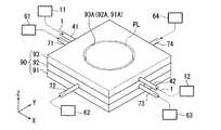
図16は本実施形態に係る液体供給機構(10)及び液体回収機構(20)を示す概略斜視図である。図16において、液体供給機構(10)は、第1、第2液体供給部11、12と、第1、第2液体供給部11、12のそれぞれに接続する第1、第2供給管41、42とを備えている。液体回収機構(20)は、第1〜第4液体回収部61〜64と、第1〜第4液体回収部61〜64のそれぞれに接続する第1〜第4回収管71〜74とを備えている。そして、第1、第2供給管41、42のそれぞれの一端部は第1、第2液体供給部11、12に接続され、他端部は流路形成部材90により形成される後述する供給流路に接続される。第1〜第4回収管71〜74のそれぞれの一端部は第1〜第4液体回収部61〜64に接続され、他端部は流路形成部材90により形成される後述する回収流路に接続される。 FIG. 16 is a schematic perspective view showing the liquid supply mechanism (10) and the liquid recovery mechanism (20) according to this embodiment. In FIG. 16, the liquid supply mechanism (10) includes first and second
流路形成部材90は、第1部材91と、第1部材91の上部に配置され第2部材92と、第2部材92の上部に配置され第3部材93とを備えている。流路形成部材90は投影光学系PLを囲むように配置され、この流路形成部材90を構成する第1〜第3部材91〜93のそれぞれは、同一外寸で矩形の板状部材であってその中央部に投影光学系PLを配置可能な穴部91A〜93Aを有している。穴部91A〜93Aは互いに連通するように形成されている。また、第1、第2供給管41、42は、第1〜第3部材のうち最上段の第3部材93に接続され、第1〜第4回収管71〜74は、中段の第2部材92に接続されている。 The flow
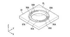
図17は、第1〜第3部材のうち最下段に配置される第1部材91を示す斜視図である。第1部材91は、投影光学系PLの−X側に形成され、基板Pに液体1を供給する供給口を形成する第1供給穴部94Aと、投影光学系PLの+X側に形成され、基板P上に液体を供給する供給口を形成する第2供給穴部95Aとを備えている。第1供給穴部94A及び第2供給穴部95Aのそれぞれは平面視略円弧状に形成されている。更に、第1部材91は、投影光学系PLの−X側に形成され、基板P上の液体を回収する回収口を形成する第1回収穴部96Aと、投影光学系PLの−Y側に形成され、基板P上の液体を回収する回収口を形成する第2回収穴部97Aと、投影光学系PLの+X側に形成され、基板P上の液体を回収する回収口を形成する第3回収穴部98Aと、投影光学系PLの+Y側に形成され、基板P上の液体を回収する回収口を形成する第4回収穴部99Aとを備えている。第1〜第4回収穴部96A〜99Aのそれぞれは平面視略円弧状に形成されており、投影光学系PLの周囲に沿って略等間隔に設けられている。また、回収穴部96A〜99Aのそれぞれは、供給穴部94A、95Bより投影光学系PLに対して外側に設けられている。 FIG. 17 is a perspective view showing the
図18は、第1〜第3部材のうち中段に配置される第2部材92を示す斜視図であって、図18(a)は上側から見た斜視図、図18(b)は下側から見上げた斜視図である。
第2部材92は、投影光学系PLの−X側に形成され、第1部材91の第1供給穴部94Aに接続する第3供給穴部94Bと、投影光学系PLの+X側に形成され、第1部材91の第2供給穴部95Aに接続する第4供給穴部95Bとを備えている。第3、第4供給穴部94B、95Bそれぞれの形状及び大きさは、第1、第2供給穴部94A、95Aに対応している。18A and 18B are perspective views showing the
The
更に、第2部材92はその下面に、投影光学系PLの−X側に形成され、第1部材91の第1回収穴部96Aに接続する第1回収溝部96Bと、投影光学系PLの−Y側に形成され、第1部材91の第2回収穴部97Aに接続する第2回収溝部97Bと、投影光学系PLの+X側に形成され、第1部材91の第3回収穴部98Aに接続する第3回収溝部98Bと、投影光学系PLの+Y側に形成され、第1部材91の第4回収穴部99Aに接続する第4回収溝部99Bとを備えている。第1〜第4回収溝部96B〜99Bのそれぞれは、第1〜第4回収穴部96A〜99Aの形状及び大きさに対応するように平面視略円弧状に形成されており、投影光学系PLの周囲に沿って略等間隔に設けられている。また、第1回収管71と第1回収溝部96Bとは、テーパ状溝部96Tを介して接続されている。テーパ状溝部96Tは、第1回収管71に対する接続部から第1回収溝部96Bに向かって水平方向に漸次拡がるように形成されている。同様に、第2回収管72と第2回収溝部97Bとはテーパ状溝部97Tを介して接続されており、第3回収管73と第3回収溝部98Bとはテーパ状溝部98Tを介して接続されており、第4回収管74と第4回収溝部99Bとはテーパ状溝部99Tを介して接続されている。 Further, the
図19は、第1〜第3部材のうち最上段に配置される第3部材93を示す斜視図であって、図19(a)は上側から見た斜視図、図19(b)は下側から見上げた斜視図である。第3部材93はその下面に、投影光学系PLの−X側に形成され、第2部材92の第3供給穴部94Bに接続する第1供給溝部94Cと、投影光学系PLの+X側に形成され、第2部材92の第4供給穴部95Bに接続する第2供給溝部95Cとを備えている。第1、第2供給溝部94C、95Cそれぞれの形状及び大きさは、第3、第4供給穴部94B、95B(ひいては第1、第2供給穴部94A、95A)に対応するように平面視略円弧状に形成されている。また、第1供給管41と第1供給溝部94Cとは、テーパ状溝部94Tを介して接続されている。テーパ状溝部94Tは、第1供給管41に対する接続部から第1供給溝部94Cに向かって水平方向に漸次拡がるように形成されている。同様に、第2供給管42と第2供給溝部95Cとはテーパ状溝部95Tを介して接続されている。 FIG. 19 is a perspective view showing the
第1〜第3部材91〜93は、例えばステンレスやチタン、アルミニウム、あるいはこれらを含む合金等の金属により形成されており、各部材91〜93の穴部や溝部は例えば放電加工により形成される。放電加工により各部材91〜93に対して加工した後、これら各部材91〜93を接着剤、熱圧着法等を用いて接合することにより、流路形成部材90が形成される。各部材91〜93を積層して接合することで、テーパ状溝部94T、第1供給溝部94C、第3供給穴部94B、及び第1供給穴部94Aのそれぞれが接続(連通)され、これらにより第1供給管41に接続(連通)する供給流路が形成される。同様に、テーパ状溝部95T、第2供給溝部95C、第4供給穴部95B、及び第2供給穴部95Aのそれぞれが接続(連通)されることで、第2供給管41に接続(連通)する供給流路が形成される。そして、第1、第2液体供給部11、12のそれぞれから送出された液体1は、第1、第2供給管41、42、及び上記供給流路を介して基板P上に供給される。すなわち、板状部材91〜93が積層されることで、液体供給流路が形成される。 The 1st-3rd members 91-93 are formed, for example with metals, such as stainless steel, titanium, aluminum, or an alloy containing these, and the hole part and groove part of each member 91-93 are formed by electrical discharge machining, for example. . After processing the
また、テーパ状溝部96T、第1回収溝部96B、及び第1回収穴部96Aのそれぞれが接続(連通)されることで、第1回収管71に接続(連通)する回収流路が形成される。同様に、テーパ状溝部97T、第2回収溝部97B、及び第2回収穴部97Aのそれぞれが接続(連通)されることで、第2回収管72に接続(連通)する回収流路が形成され、テーパ状溝部98T、第3回収溝部98B、及び第3回収穴部98Aのそれぞれが接続(連通)されることで、第3回収管73に接続(連通)する回収流路が形成され、テーパ状溝部99T、第4回収溝部99B、及び第4回収穴部99Aのそれぞれが接続(連通)されることで、第4回収管74に接続(連通)する回収流路が形成される。すなわち、板状部材91〜93が積層されることで、液体回収流路が形成される。そして、基板P上の液体は、上記回収流路、及び第1〜第4回収管71〜74のそれぞれを介して回収される。 Further, each of the tapered
このとき、第1、第2供給管41、42のそれぞれにはテーパ状溝部94T、95Tが接続されるので、図14を参照して説明した実施形態同様、Y軸方向を長手方向とする供給口の各位置において均一に液体供給を行うことができる。同様に、回収管71〜74のそれぞれにもテーパ状溝部が接続されるので、液体回収を均一な回収力で回収することができる。 At this time, since the
そして、板状部材である第1〜第3部材91〜93のそれぞれで流路形成部材90を形成したことにより、例えば液体回収の際に空気をかみこんで液体を吸引した際に発生する振動を、流路形成部材90で吸収することができる。また、複数の板状部材91〜93のそれぞれに対して放電加工等の加工を施して流路の一部を形成し、これらを組み合わせることで液体の流路を形成するようにしたので、供給流路及び回収流路のそれぞれを容易に形成することができる。 Then, by forming the flow
なお、流路形成部材90を形成する複数の部材91〜93のうち、最下段に配置される第1部材91の下面の第1〜第4回収穴部96A〜99Aの周囲にXY平面に対して傾斜した面を設けて、その面を親液処理することにより、液体回収機構で回収しきれなかった液体を捕捉するトラップ面として用いるようにしてもよい。また、流路形成部材90を形成する部材91〜93は四角形の板状部材であるが、円形の板状部材を使ってもよいし、X方向に長い楕円状の板状部材にしてもよい。 Of the plurality of
また上述の流路形成部材90は、その内部に供給流路と回収流路の両方が形成されているが、どちらか一方のみを流路形成部材90の内部に設けるようにしてもよい。また、複数の部材を積層して形成される流路形成部材を供給流路用と回収流路用とに別々に備えるようにしてもよい。 Moreover, although both the supply flow path and the recovery flow path are formed in the flow
次に、本発明の更なる別実施形態について説明する。上述したように、供給部材13、14を含む液体供給機構10、及び回収部材22を含む液体回収機構20のそれぞれは、投影光学系PL及びこの投影光学系PLを支持する支持部材以外の支持部材で支持することが好ましい。以下、液体供給機構10及び液体回収機構20を支持する支持構造について図20を参照しながら説明する。 Next, still another embodiment of the present invention will be described. As described above, each of the
図20は、液体供給機構10及び液体回収機構20の支持構造を示す概略図である。図20において、露光装置EXは、投影光学系PLを支持する鏡筒定盤(第1支持部材)100と、鏡筒定盤100、マスクステージMST、及び基板ステージPSTを支持するメインフレーム(第2支持部材)102とを備えている。なお、図20では、Zステージ及びXYステージは一体で図示されている。メインフレーム102は、クリーンルームなどの床面上に脚部108を介してほぼ水平に設置されている。メインフレーム102には、内側に向けて突出する上側段部102A及び下側段部102Bが形成されている。 FIG. 20 is a schematic view showing a support structure for the
照明光学系ILは、メインフレーム102の上部に固定された支持フレーム120により支持されている。メインフレーム102の上側段部102Aには、防振装置122を介してマスク定盤124が支持されている。マスクステージMST及びマスク定盤124の中央部にはマスクMのパターン像を通過させる開口部が形成されている。マスクステージMSTの下面には非接触軸受である気体軸受(エアベアリング)126が複数設けられている。マスクステージMSTはエアベアリング126によりマスク定盤124の上面(ガイド面)に対して非接触支持されており、マスクステージ駆動装置によりXY平面内で2次元移動可能及びθZ方向に微小回転可能である。 The illumination optical system IL is supported by a
投影光学系PLを保持する鏡筒PKの外周にはフランジ104が設けられており、投影光学系PLはこのフランジ104を介して鏡筒定盤100に支持されている。鏡筒定盤100とメインフレーム102の下側段部102Bとの間にはエアマウントなどを含む防振装置106が配置されており、投影光学系PLを支持する鏡筒定盤100はメインフレーム102の下側段部102Bに防振装置106を介して支持されている。この防振装置106によって、メインフレーム102の振動が、投影光学系PLを支持する鏡筒定盤100に伝わらないように、鏡筒定盤100とメインフレーム102とが振動に関して分離されている。 A
基板ステージPSTの下面には複数の非接触軸受である気体軸受(エアベアリング)130が設けられている。また、メインフレーム102上には、エアマウント等を含む防振装置110を介してステージベース112が支持されている。基板ステージPSTはエアベアリング130によりステージベース112の上面(ガイド面)に対して非接触支持されており、基板ステージ駆動装置により、XY平面内で2次元移動可能及びθZ方向に微小回転可能である。更に、基板ステージPSTは、Z軸方向、θX方向、及びθY方向にも移動可能である。この防振装置110によって、メインフレーム102の振動が、基板ステージPSTを非接触支持するステージベース112に伝わらないように、ステージベース112とメインフレーム102とが振動に関して分離されている。 A plurality of gas bearings (air bearings) 130 which are non-contact bearings are provided on the lower surface of the substrate stage PST. A
基板ステージPST上の+X側の所定位置には移動鏡55が設けられ、鏡筒PKの+X側の所定位置には参照鏡(固定鏡)114が設けられている。また、移動鏡55及び参照鏡114に対向する位置にはレーザ干渉計56が設けられている。レーザ干渉計56は、鏡筒定盤100に取り付けられているため、レーザ干渉計56と液体供給機構10及び液体回収機構20とは振動に関して離れている。レーザ干渉計56は、移動鏡55に測長ビーム(測定光)を照射するとともに、参照鏡114に参照ビーム(参照光)を照射する。
照射した測長ビーム及び参照ビームに基づく移動鏡55及び参照鏡114それぞれからの反射光はレーザ干渉計56の受光部で受光され、レーザ干渉計56はこれら光を干渉し、参照ビームの光路長を基準とした測長ビームの光路長の変化量、ひいては、参照鏡114を基準とした移動鏡55の位置情報、すなわち基板ステージPSTの位置情報を計測する。同様に、不図示ではあるが、基板ステージPST上及び鏡筒PKの+Y側にも移動鏡及び参照鏡が設けられ、これらに対向する位置にはレーザ干渉計が設けられている。A
Reflected light from each of the
また、鏡筒定盤100には、基板Pのフォーカス位置(Z位置)及び傾斜を計測するためのオートフォーカス検出系や基板P上のアライメントマークを検出するアライメント系等、不図示の計測系も支持されており、これらの計測系も、メインフレーム102、液体供給機構10、液体回収機構20とは振動に関して分離されることになる。 The lens
液体供給機構10及び液体回収機構20は、メインフレーム102の下側段部102Bに支持されている。本実施形態では、液体供給機構10を構成する第1、第2供給部材13、14、供給管11A、12A、及び液体回収機構20を構成する回収部材22、回収管21Aなどが、支持部材140によって支持され、この支持部材140がメインフレーム102の下側段部102Bに接続された構成となっている。なお、図20では、供給部材13、14、回収部材22、供給管11A、12A、及び回収管21Aなどは簡略化して図示されている。 The
このように、投影光学系PLを支持する鏡筒定盤100と振動に関して分離されたメインフレーム102で液体供給機構10及び液体回収機構20を支持することによって、液体供給機構10及び液体回収機構20と投影光学系PLとは振動に関して分離されたことになる。したがって、液体供給の際、あるいは液体回収の際に生じる振動が、鏡筒定盤100を介して投影光学系PL、レーザ干渉計56、及びオートフォーカス検出系やアライメント系等の計測系に伝わることがない。したがって、投影光学系が振動することでパターン像が劣化するといった不都合の発生を防止でき、また、基板ステージ(基板P)の位置制御を精度良く行うことができるため、パターン像を基板上に精度良く投影することができる。また、基板ステージPSTを支持するステージベース112と振動に関して分離されたメインフレーム102で液体供給機構10及び液体回収機構20を支持することによって、液体供給機構10及び液体回収機構20とステージベース112とは振動に関して分離されたことになる。したがって、液体供給の際、あるいは液体回収の際に生じる振動が、ステージベース112に伝わることもなく、基板ステージPSTの位置決め精度、あるいは移動精度を低下させる不都合が生じるのを防止することができる。 In this way, the
なお、本実施形態においては、メインフレーム102に液体供給機構10及び液体回収機構20が一体的に支持されているが、液体供給機構10と液体回収機構20とを分離して、メインフレーム102に取り付けるようにしてもよい。更にメインフレーム102とは別の支持部材をクリーンルーム等の床に配置し、この支持部材に液体供給機構と液体回収機構とを支持するようにしてもよい。 In the present embodiment, the
上述したように、本実施形態における液体1には純水が用いられている。純水は、半導体製造工場等で容易に大量に入手できるとともに、基板P上のフォトレジストや光学素子(レンズ)等に対する悪影響がない利点がある。また、純水は環境に対する悪影響がないとともに、不純物の含有量が極めて低いため、基板Pの表面、及び投影光学系PLの先端面に設けられている光学素子の表面を洗浄する作用も期待できる。そして、波長が193nm程度の露光光ELに対する純水(水)の屈折率nはほぼ1.44程度と言われており、露光光ELの光源としてArFエキシマレーザ光(波長193nm)を用いた場合、基板P上では1/n、すなわち約134nm程度に短波長化されて高い解像度が得られる。
更に、焦点深度は空気中に比べて約n倍、すなわち約1.44倍程度に拡大されるため、空気中で使用する場合と同程度の焦点深度が確保できればよい場合には、投影光学系PLの開口数をより増加させることができ、この点でも解像度が向上する。As described above, pure water is used for the liquid 1 in the present embodiment. Pure water has an advantage that it can be easily obtained in large quantities at a semiconductor manufacturing factory or the like, and has no adverse effect on the photoresist, optical element (lens), etc. on the substrate P. In addition, pure water has no adverse effects on the environment, and since the impurity content is extremely low, it can be expected to clean the surface of the substrate P and the surface of the optical element provided on the front end surface of the projection optical system PL. . The refractive index n of pure water (water) with respect to the exposure light EL having a wavelength of about 193 nm is said to be about 1.44, and when ArF excimer laser light (wavelength 193 nm) is used as the light source of the exposure light EL On the substrate P, the wavelength is shortened to 1 / n, that is, about 134 nm, and a high resolution is obtained.
Furthermore, since the depth of focus is expanded to about n times, that is, about 1.44 times compared with that in the air, the projection optical system can be used when it is sufficient to ensure the same depth of focus as that used in the air. The numerical aperture of PL can be further increased, and the resolution is improved also in this respect.
なお、上述したように液浸法を用いた場合には、投影光学系の開口数NAが0.9〜1.3になることもある。このように投影光学系の開口数NAが大きくなる場合には、従来から露光光として用いられているランダム偏光光では偏光効果によって結像性能が悪化することもあるので、偏光照明を用いるのが望ましい。その場合、マスク(レチクル)のライン・アンド・スペースパターンのラインパターンの長手方向に合わせた直線偏光照明を行い、マスク(レチクル)のパターンからは、S偏光成分(ラインパターンの長手方向に沿った偏光方向成分)の回折光が多く射出されるようにするとよい。投影光学系PLと基板P表面に塗布されたレジストとの間が液体で満たされている場合、投影光学系PLと基板P表面に塗布されたレジストとの間が空気(気体)で満たされている場合に比べて、コントラストの向上に寄与するS偏光成分の回折光のレジスト表面での透過率が高くなるため、投影光学系の開口数NAが1.0を越えるような場合でも高い結像性能を得ることができる。また、位相シフトマスクやラインパターンの長手方向に合わせた斜入射照明法(特にダイボール照明法)等を適宜組み合わせると更に効果的である。なお、ラインパターンの長手方向に合わせた斜入射照明法については、例えば特開平6−188169号公報に開示されており、本国際出願で指定または選択された国の法令で許容される限りにおいて、その開示を援用して本文の記載の一部とする。 As described above, when the liquid immersion method is used, the numerical aperture NA of the projection optical system may be 0.9 to 1.3. When the numerical aperture NA of the projection optical system becomes large in this way, the imaging performance may deteriorate due to the polarization effect with random polarized light conventionally used as exposure light. desirable. In that case, linearly polarized illumination is performed in accordance with the longitudinal direction of the line pattern of the mask (reticle) line-and-space pattern, and the S-polarized component (along the longitudinal direction of the line pattern) is generated from the mask (reticle) pattern. It is preferable that a large amount of diffracted light (polarization direction component) is emitted. When the space between the projection optical system PL and the resist applied on the surface of the substrate P is filled with a liquid, the space between the projection optical system PL and the resist applied on the surface of the substrate P is filled with air (gas). Compared with the case where the diffracted light of the s-polarized light component contributing to the contrast is increased, the transmittance on the resist surface is increased, so that even when the numerical aperture NA of the projection optical system exceeds 1.0, high image formation is achieved. Performance can be obtained. Further, it is more effective to appropriately combine a phase shift mask or an oblique incidence illumination method (particularly a die ball illumination method) matched to the longitudinal direction of the line pattern. Incidentally, the oblique incidence illumination method adapted to the longitudinal direction of the line pattern is disclosed in, for example, Japanese Patent Application Laid-Open No. 6-188169, and as long as allowed by the laws of the country designated or selected in this international application, The disclosure is incorporated herein by reference.
本実施形態では、投影光学系PLの先端に光学素子2としてレンズが取り付けられており、このレンズにより投影光学系PLの光学特性、例えば収差(球面収差、コマ収差等)の調整を行うことができる。なお、光学素子2としては前記光学特性を調整する光学プレートであってもよい。一方、液体1と接触する光学素子2を、レンズより安価な平行平面板とすることも可能である。光学素子2を平行平面板とすることにより、露光装置EXの運搬、組立、調整時等において投影光学系PLの透過率、基板P上での露光光ELの照度、及び照度分布の均一性を低下させる物質(例えばシリコン系有機物等)がその平行平面板に付着しても、液体1を供給する直前にその平行平面板を交換するだけでよく、液体1と接触する光学素子をレンズとする場合に比べてその交換コストが低くなるという利点がある。すなわち、露光光ELの照射によりレジストから発生する飛散粒子、または液体1中の不純物の付着などに起因して液体1に接触する光学素子の表面が汚れるため、その光学素子を定期的に交換する必要があるが、この光学素子を安価な平行平面板とすることにより、レンズに比べて交換部品のコストが低く、且つ交換に要する時間を短くすることができ、メンテナンスコスト(ランニングコスト)の上昇やスループットの低下を抑えることができる。 In the present embodiment, a lens is attached as the
なお、液体1の流れによって生じる投影光学系PLの先端の光学素子と基板Pとの間の圧力が大きい場合には、その光学素子を交換可能とするのではなく、その圧力によって光学素子が動かないように堅固に固定してもよい。 When the pressure between the optical element at the tip of the projection optical system PL generated by the flow of the
なお、本実施形態の液体1は水であるが、水以外の液体であってもよい、例えば、露光光ELの光源がF2レーザである場合、このF2レーザ光は水を透過しないので、液体1としてはF2レーザ光を透過可能な例えば過フッ化ポリエーテル(PFPE)やフッ素系オイル等のフッ素系流体であってもよい。この場合、トラップ面31をはじめとする液体1と接触する部分には、例えばフッ素を含む極性の小さい分子構造の物質で薄膜を形成することで親液化処理する。また、液体1としては、その他にも、露光光ELに対する透過性があってできるだけ屈折率が高く、投影光学系PLや基板P表面に塗布されているフォトレジストに対して安定なもの(例えばセダー油)を用いることも可能である。この場合も表面処理は用いる液体1の極性に応じて行われる。Although the
なお、上述の投影光学系PLは、その像面側を液体1(純水)で満たした液浸状態で、その結像性能が最適となるように構成(設計)されているが、投影光学系PLの一部の光学素子(基板Pに近い光学素子)を交換することによって、その像面側に液体がない非液浸状態や、その像面側を別の液体で満たした液浸状態でも所望の結像性能が得られるような構成(設計)にして もよい。投影光学系PLをこのような構成にしておくことで、例えば、大きな焦点深度DOFが必要な場合は、露光装置EXを液浸状態で使用し、高スループットが要求される場合には、一部の光学素子を交換して非液浸状態で露光装置EXを使用することができる。その場合、一部の光学素子の交換した後の結像性能を測定するために、基板ステージPST上に特開2002―14005号(対応米国特許公開20020041377)に開示されている空間像センサや国際公開第02/63664号公報に開示されているような波面収差測定センサを配置しておくのが望ましい。もちろん、波面収差測定用のマスクを用いてもよいし、その結像性能の測定結果に基づいて、それぞれの状態で所望の結像性能が得られるように、一部の光学素子を動かしたり、露光光ELの波長の微調整を行なうようにしてもよい。 The above-described projection optical system PL is configured (designed) so that its imaging performance is optimized in an immersion state where the image plane side is filled with liquid 1 (pure water). By exchanging some optical elements of the system PL (optical elements close to the substrate P), there is no liquid in the image plane side, or an immersion state in which the image plane side is filled with another liquid. However, the configuration (design) may be such that desired imaging performance can be obtained. By configuring the projection optical system PL in such a configuration, for example, when a large depth of focus DOF is required, the exposure apparatus EX is used in a liquid immersion state, and when high throughput is required, partly The exposure apparatus EX can be used in a non-immersion state by replacing the optical elements. In that case, in order to measure the imaging performance after replacement of some optical elements, a spatial image sensor disclosed in Japanese Patent Laid-Open No. 2002-14005 (corresponding US Patent Publication 20020041377) or international It is desirable to arrange a wavefront aberration measuring sensor as disclosed in Japanese Patent Publication No. 02/63664. Of course, a mask for wavefront aberration measurement may be used, and based on the measurement results of the imaging performance, some optical elements may be moved so that a desired imaging performance is obtained in each state, Fine adjustment of the wavelength of the exposure light EL may be performed.
また一部の光学素子の交換は、露光装置EXに投影光学系PLを搭載したまま行なうのが望ましいが、露光装置EXから投影光学系PLを外して行なうようにしてもよい。 Further, it is desirable to replace some of the optical elements while the projection optical system PL is mounted on the exposure apparatus EX. However, the projection optical system PL may be removed from the exposure apparatus EX.
なお、上記各実施形態の基板Pとしては、半導体デバイス製造用の半導体ウエハのみならず、ディスプレイデバイス用のガラス基板や、薄膜磁気ヘッド用のセラミックウエハ、あるいは露光装置で用いられるマスクまたはレチクルの原版(合成石英、シリコンウエハ)等が適用される。 The substrate P in each of the above embodiments is not only a semiconductor wafer for manufacturing a semiconductor device, but also a glass substrate for a display device, a ceramic wafer for a thin film magnetic head, or an original mask or reticle used in an exposure apparatus. (Synthetic quartz, silicon wafer) or the like is applied.
露光装置EXとしては、マスクMと基板Pとを同期移動してマスクMのパターンを走査露光するステップ・アンド・スキャン方式の走査型露光装置(スキャニングステッパ)の他に、マスクMと基板Pとを静止した状態でマスクMのパターンを一括露光し、基板Pを順次ステップ移動させるステップ・アンド・リピート方式の投影露光装置(ステッパ)にも適用することができる。また、本発明は基板P上で少なくとも2つのパターンを部分的に重ねて転写するステップ・アンド・スティッチ方式の露光装置にも適用できる。 As the exposure apparatus EX, in addition to the step-and-scan type scanning exposure apparatus (scanning stepper) that scans and exposes the pattern of the mask M by moving the mask M and the substrate P synchronously, the mask M and the substrate P Can be applied to a step-and-repeat type projection exposure apparatus (stepper) in which the pattern of the mask M is collectively exposed while the substrate P is stationary and the substrate P is sequentially moved stepwise. The present invention can also be applied to a step-and-stitch type exposure apparatus that partially transfers at least two patterns on the substrate P.
また、本発明は、ツインステージ型の露光装置にも適用できる。ツインステージ型の露光装置の構造及び露光動作は、例えば特開平10−163099号及び特開平10−214783号(対応米国特許6,341,007、6,400,441、6,549,269及び6,590,634)、特表2000−505958号(対応米国特許5,969,441)あるいは米国特許6,208,407に開示されており、本国際出願で指定または選択された国の法令で許容される限りにおいて、それらの開示を援用して本文の記載の一部とする。 The present invention can also be applied to a twin stage type exposure apparatus. The structure and exposure operation of a twin stage type exposure apparatus are disclosed in, for example, Japanese Patent Laid-Open Nos. 10-163099 and 10-214783 (corresponding US Pat. Nos. 6,341,007, 6,400,441, 6,549,269 and 6). , 590, 634), JP 2000-505958 (corresponding US Pat. No. 5,969,441) or US Pat. No. 6,208,407, and is permitted by the laws of the country designated or selected in this international application. Insofar as possible, those disclosures are incorporated herein by reference.
露光装置EXの種類としては、基板Pに半導体素子パターンを露光する半導体素子製造用の露光装置に限られず、液晶表示素子製造用又はディスプレイ製造用の露光装置や、薄膜磁気ヘッド、撮像素子(CCD)あるいはレチクル又はマスクなどを製造するための露光装置などにも広く適用できる。 The type of the exposure apparatus EX is not limited to an exposure apparatus for manufacturing a semiconductor element that exposes a semiconductor element pattern on the substrate P, but an exposure apparatus for manufacturing a liquid crystal display element or a display, a thin film magnetic head, an image sensor (CCD). ) Or an exposure apparatus for manufacturing reticles or masks.
基板ステージPSTやマスクステージMSTにリニアモータを用いる場合は、エアベアリングを用いたエア浮上型およびローレンツ力またはリアクタンス力を用いた磁気浮上型のどちらを用いてもよい。また、各ステージPST、MSTは、ガイドに沿って移動するタイプでもよく、ガイドを設けないガイドレスタイプであってもよい。ステージにリニアモータを用いた例は、米国特許5,623,853及び5,528,118に開示されており、それぞれ本国際出願で指定または選択された国の法令で許容される限りにおいて、これらの文献の記載内容を援用して本文の記載の一部とする。 When a linear motor is used for the substrate stage PST and the mask stage MST, either an air levitation type using an air bearing or a magnetic levitation type using a Lorentz force or a reactance force may be used. Each stage PST, MST may be a type that moves along a guide, or may be a guideless type that does not have a guide. Examples using linear motors for the stages are disclosed in US Pat. Nos. 5,623,853 and 5,528,118, respectively, as long as permitted by national legislation designated or selected in this international application. The contents of the document are incorporated into the text.
各ステージPST、MSTの駆動機構としては、二次元に磁石を配置した磁石ユニットと、二次元にコイルを配置した電機子ユニットとを対向させ電磁力により各ステージPST、MSTを駆動する平面モータを用いてもよい。この場合、磁石ユニットと電機子ユニットとのいずれか一方をステージPST、MSTに接続し、磁石ユニットと電機子ユニットとの他方をステージPST、MSTの移動面側に設ければよい。 As a driving mechanism for each stage PST, MST, a planar motor that drives each stage PST, MST by electromagnetic force with a magnet unit having a two-dimensionally arranged magnet and an armature unit having a two-dimensionally arranged coil facing each other is provided. It may be used. In this case, either one of the magnet unit and the armature unit may be connected to the stages PST and MST, and the other of the magnet unit and the armature unit may be provided on the moving surface side of the stages PST and MST.
基板ステージPSTの移動により発生する反力は、投影光学系PLに伝わらないように、フレーム部材を用いて機械的に床(大地)に逃がしてもよい。この反力の処理方法は、例えば、米国特許5,528,118(特開平8−166475号公報)に詳細に開示されており、本国際出願で指定または選択された国の法令で許容される限りにおいて、この文献の記載内容を援用して本文の記載の一部とする。 The reaction force generated by the movement of the substrate stage PST may be released mechanically to the floor (ground) using a frame member so as not to be transmitted to the projection optical system PL. This reaction force processing method is disclosed in detail, for example, in US Pat. No. 5,528,118 (Japanese Patent Laid-Open No. Hei 8-166475), and allowed by the laws of the country designated or selected in this international application. As far as this is concerned, the contents of this document are incorporated into the text.
マスクステージMSTの移動により発生する反力は、投影光学系PLに伝わらないように、フレーム部材を用いて機械的に床(大地)に逃がしてもよい。この反力の処理方法は、例えば、米国特許第5,874,820(特開平8−330224号公報)に詳細に開示されており、本国際出願で指定または選択された国の法令で許容される限りにおいて、この文献の開示を援用して本文の記載の一部とする。 The reaction force generated by the movement of the mask stage MST may be released mechanically to the floor (ground) using a frame member so as not to be transmitted to the projection optical system PL. This reaction force processing method is disclosed in detail, for example, in US Pat. No. 5,874,820 (Japanese Patent Laid-Open No. 8-330224) and is permitted by the laws of the country designated or selected in this international application. As far as possible, the disclosure of this document is incorporated into the text.
以上のように、本願実施形態の露光装置EXは、本願特許請求の範囲に挙げられた各構成要素を含む各種サブシステムを、所定の機械的精度、電気的精度、光学的精度を保つように、組み立てることで製造される。これら各種精度を確保するために、この組み立ての前後には、各種光学系については光学的精度を達成するための調整、各種機械系については機械的精度を達成するための調整、各種電気系については電気的精度を達成するための調整が行われる。各種サブシステムから露光装置への組み立て工程は、各種サブシステム相互の、機械的接続、電気回路の配線接続、気圧回路の配管接続等が含まれる。この各種サブシステムから露光装置への組み立て工程の前に、各サブシステム個々の組み立て工程があることはいうまでもない。各種サブシステムの露光装置への組み立て工程が終了したら、総合調整が行われ、露光装置全体としての各種精度が確保される。なお、露光装置の製造は温度およびクリーン度等が管理されたクリーンルームで行うことが望ましい。 As described above, the exposure apparatus EX according to the present embodiment maintains various mechanical subsystems including the respective constituent elements recited in the claims of the present application so as to maintain predetermined mechanical accuracy, electrical accuracy, and optical accuracy. Manufactured by assembling. In order to ensure these various accuracies, before and after assembly, various optical systems are adjusted to achieve optical accuracy, various mechanical systems are adjusted to achieve mechanical accuracy, and various electrical systems are Adjustments are made to achieve electrical accuracy. The assembly process from the various subsystems to the exposure apparatus includes mechanical connection, electrical circuit wiring connection, pneumatic circuit piping connection and the like between the various subsystems. Needless to say, there is an assembly process for each subsystem before the assembly process from the various subsystems to the exposure apparatus. When the assembly process of the various subsystems to the exposure apparatus is completed, comprehensive adjustment is performed to ensure various accuracies as the entire exposure apparatus. The exposure apparatus is preferably manufactured in a clean room where the temperature, cleanliness, etc. are controlled.
半導体デバイス等のマイクロデバイスは、図21に示すように、マイクロデバイスの機能・性能設計を行うステップ201、この設計ステップに基づいたマスク(レチクル)を製作するステップ202、デバイスの基材である基板を製造するステップ203、前述した実施形態の露光装置EXによりマスクのパターンを基板に露光する露光処理ステップ204、デバイス組み立てステップ(ダイシング工程、ボンディング工程、パッケージ工程を含む)205、検査ステップ206等を経て製造される。 As shown in FIG. 21, a microdevice such as a semiconductor device includes a
1…液体、10…液体供給機構、11…第1液体供給部、12…第2液体供給部、13…第1供給部材、13A…供給口、14…第2供給部材、14A…供給口、20…液体回収機構、21…液体回収部、22…回収部材、22A…回収口、23…仕切部材(仕切り)、30…トラップ部材、31…トラップ面、32…フィン部材(トラップ部材)、AR1…投影領域、AR2…液浸領域、CONT…制御装置、EX…露光装置、M…マスク、P…基板、PL…投影光学系、S1〜S12…ショット領域 DESCRIPTION OF
Claims (47)
Translated fromJapanese前記パターンの像を基板に投影する投影光学系と;
前記投影光学系の投影領域を含む基板上の一部に液浸領域を形成するために基板上に液体を供給する液体供給機構と;
前記投影領域に対して異なる複数の方向に離れた複数の位置で基板上の液体の回収を同時に行う液体回収機構とを備える露光装置。An exposure apparatus that exposes a substrate by projecting an image of a predetermined pattern onto the substrate through a liquid:
A projection optical system that projects an image of the pattern onto a substrate;
A liquid supply mechanism for supplying a liquid onto the substrate in order to form an immersion region on a part of the substrate including the projection region of the projection optical system;
An exposure apparatus comprising: a liquid recovery mechanism that simultaneously recovers the liquid on the substrate at a plurality of positions separated in a plurality of different directions with respect to the projection region.
前記パターンの像を基板に投影する投影光学系と;
前記投影光学系の投影領域を含む基板上の一部に液浸領域を形成するために基板上に液体を供給する液体供給機構と;
基板上の液体の回収を複数の位置で同時に行う液体回収機構と;を備え、
前記液体回収機構は液体回収位置に応じて異なる回収力で液体を回収する露光装置。An exposure apparatus that exposes a substrate by projecting an image of a predetermined pattern onto the substrate through a liquid:
A projection optical system that projects an image of the pattern onto a substrate;
A liquid supply mechanism for supplying a liquid onto the substrate in order to form an immersion region on a part of the substrate including the projection region of the projection optical system;
A liquid recovery mechanism for simultaneously recovering the liquid on the substrate at a plurality of positions;
The liquid recovery mechanism is an exposure apparatus that recovers a liquid with a different recovery force depending on a liquid recovery position.
前記パターンの像を基板に投影する投影光学系と;
前記投影光学系の投影領域を含む基板上の一部に液浸領域を形成するために基板上に液体を供給する液体供給機構と;
前記投影領域から離れた回収位置で基板上の液体の回収を行う液体回収機構と;
前記投影領域に対して前記液体回収機構による液体回収位置の外側に配置され、液体を捕捉する液体トラップ面が形成されたトラップ部材とを備える露光装置。An exposure apparatus that exposes a substrate by projecting an image of a predetermined pattern onto the substrate through a liquid:
A projection optical system that projects an image of the pattern onto a substrate;
A liquid supply mechanism for supplying a liquid onto the substrate in order to form an immersion region on a part of the substrate including the projection region of the projection optical system;
A liquid recovery mechanism for recovering the liquid on the substrate at a recovery position away from the projection area;
An exposure apparatus comprising: a trap member disposed outside a liquid recovery position by the liquid recovery mechanism with respect to the projection region, and having a liquid trap surface for capturing the liquid.
前記パターンの像を基板に投影する投影光学系と;
前記投影光学系の投影領域を含む基板上の一部に液浸領域を形成するために基板上に液体を供給する液体供給機構と;
前記投影領域から離れた回収位置で基板上の液体の回収を行う液体回収機構と;を備え、
前記液体供給機構による液体の供給は、前記液体回収機構の液体回収位置と前記投影領域との間で行われる露光装置。An exposure apparatus that exposes a substrate by projecting an image of a predetermined pattern onto the substrate through a liquid:
A projection optical system that projects an image of the pattern onto a substrate;
A liquid supply mechanism for supplying a liquid onto the substrate in order to form an immersion region on a part of the substrate including the projection region of the projection optical system;
A liquid recovery mechanism for recovering the liquid on the substrate at a recovery position away from the projection region;
An exposure apparatus in which liquid is supplied by the liquid supply mechanism between a liquid recovery position of the liquid recovery mechanism and the projection area.
前記投影光学系の先端の液体接触面との親和性が、基板表面との親和性よりも高い液体を、前記投影光学系の投影領域を含む基板上の一部に液浸領域を形成するために供給することと;
前記液浸領域に供給された液体を介して所定パターンの像を基板に投影すること;とを含む露光方法。An exposure method for exposing a substrate by projecting an image by a projection optical system of a predetermined pattern onto the substrate through a liquid:
In order to form a liquid immersion area on a part of the substrate including the projection area of the projection optical system, the liquid having a higher affinity with the liquid contact surface at the tip of the projection optical system than the affinity with the substrate surface. Supplying to;
Projecting an image of a predetermined pattern onto the substrate through the liquid supplied to the immersion area.
前記パターンの像を基板に投影する投影光学系と;
前記基板上に液体を供給する供給流路を有する液体供給機構と;
供給された液体を回収する回収流路を有する液体回収機構と;を備え、
前記供給流路と回収流路の少なくとも一方が、複数の板状部材が積層された積層部材中に形成されている露光装置。An exposure apparatus that exposes a substrate by projecting an image of a predetermined pattern onto the substrate through a liquid:
A projection optical system that projects an image of the pattern onto a substrate;
A liquid supply mechanism having a supply channel for supplying a liquid onto the substrate;
A liquid recovery mechanism having a recovery flow path for recovering the supplied liquid;
An exposure apparatus in which at least one of the supply channel and the recovery channel is formed in a laminated member in which a plurality of plate-like members are laminated.
前記パターンの像を基板に投影する投影光学系と;
前記投影光学系の投影領域を含む基板上の一部に液浸領域を形成するために基板上に液体を供給する液体供給機構と;を備え、
前記液体供給機構は、投影光学系とは振動的に分離されている露光装置。An exposure apparatus that exposes a substrate by projecting an image of a predetermined pattern onto the substrate through a liquid:
A projection optical system that projects an image of the pattern onto a substrate;
A liquid supply mechanism for supplying a liquid onto the substrate in order to form a liquid immersion region on a part of the substrate including the projection region of the projection optical system;
The liquid supply mechanism is an exposure apparatus that is vibrationally separated from the projection optical system.
前記パターンの像を基板に投影する投影光学系と;
前記投影光学系の投影領域を含む基板上の一部に供給された液体を回収する液体回収機構と;を備え、
前記液体回収機構は、投影光学系とは振動的に分離されている露光装置。An exposure apparatus that exposes a substrate by projecting an image of a predetermined pattern onto the substrate through a liquid:
A projection optical system that projects an image of the pattern onto a substrate;
A liquid recovery mechanism for recovering a liquid supplied to a part on a substrate including a projection area of the projection optical system;
The liquid recovery mechanism is an exposure apparatus that is vibrationally separated from the projection optical system.
前記パターンの像を基板に投影する投影光学系と;
前記投影光学系の投影領域を含む基板上の一部に液浸領域を形成するために、前記基板と対向するように配置された供給口から液体を供給する液体供給機構と;を備え、
前記液体供給機構は、前記基板上の複数のショット領域の露光処理が行なわれている間に前記供給口から液体を供給し続ける露光装置。An exposure apparatus that projects an image of a predetermined pattern onto a substrate through a liquid and sequentially exposes a plurality of shot areas on the substrate:
A projection optical system that projects an image of the pattern onto a substrate;
A liquid supply mechanism for supplying a liquid from a supply port arranged to face the substrate in order to form an immersion region on a part of the substrate including the projection region of the projection optical system;
The liquid supply mechanism is an exposure apparatus that continues to supply liquid from the supply port while exposure processing is performed on a plurality of shot areas on the substrate.
前記パターンの像を基板に投影する投影光学系と;
前記投影光学系の投影領域を含む基板上の一部に液浸領域を形成するために所定位置に配置された供給口から液体を供給する液体供給機構と;
前記基板と対向するように配置された回収口を有し、前記液体供給機構から供給された液体を回収する液体回収機構と;を備え、
前記液体回収機構は、前記基板上の複数のショット領域の露光処理が行なわれている間に前記回収口から液体を回収し続ける露光装置。An exposure apparatus that projects an image of a predetermined pattern onto a substrate through a liquid and sequentially exposes a plurality of shot areas on the substrate:
A projection optical system that projects an image of the pattern onto a substrate;
A liquid supply mechanism for supplying a liquid from a supply port arranged at a predetermined position in order to form a liquid immersion region on a part of the substrate including the projection region of the projection optical system;
A liquid recovery mechanism that has a recovery port arranged to face the substrate and recovers the liquid supplied from the liquid supply mechanism;
The liquid recovery mechanism is an exposure apparatus that continuously recovers liquid from the recovery port while exposure processing is performed on a plurality of shot areas on the substrate.
Priority Applications (1)
| Application Number | Priority Date | Filing Date | Title |
|---|---|---|---|
| JP2012083140AJP5699977B2 (en) | 2003-02-26 | 2012-03-30 | Exposure apparatus, exposure method, and device manufacturing method |
Applications Claiming Priority (7)
| Application Number | Priority Date | Filing Date | Title |
|---|---|---|---|
| JP2003049365 | 2003-02-26 | ||
| JP2003049365 | 2003-02-26 | ||
| JP2003110748 | 2003-04-15 | ||
| JP2003110748 | 2003-04-15 | ||
| JP2003320100 | 2003-09-11 | ||
| JP2003320100 | 2003-09-11 | ||
| JP2012083140AJP5699977B2 (en) | 2003-02-26 | 2012-03-30 | Exposure apparatus, exposure method, and device manufacturing method |
Related Parent Applications (1)
| Application Number | Title | Priority Date | Filing Date |
|---|---|---|---|
| JP2010246879ADivisionJP5353862B2 (en) | 2003-02-26 | 2010-11-02 | Exposure apparatus, exposure method, and device manufacturing method |
Related Child Applications (1)
| Application Number | Title | Priority Date | Filing Date |
|---|---|---|---|
| JP2014026886ADivisionJP5807691B2 (en) | 2003-02-26 | 2014-02-14 | Exposure apparatus, exposure method, and device manufacturing method |
Publications (2)
| Publication Number | Publication Date |
|---|---|
| JP2012129565Atrue JP2012129565A (en) | 2012-07-05 |
| JP5699977B2 JP5699977B2 (en) | 2015-04-15 |
Family
ID=33101941
Family Applications (11)
| Application Number | Title | Priority Date | Filing Date |
|---|---|---|---|
| JP2009078805AExpired - Fee RelatedJP4640516B2 (en) | 2003-02-26 | 2009-03-27 | Exposure apparatus and device manufacturing method |
| JP2009229572AExpired - Fee RelatedJP5126191B2 (en) | 2003-02-26 | 2009-10-01 | Exposure apparatus, exposure method, and device manufacturing method |
| JP2009229571AExpired - Fee RelatedJP5126190B2 (en) | 2003-02-26 | 2009-10-01 | Exposure apparatus, exposure method, and device manufacturing method |
| JP2010246879AExpired - Fee RelatedJP5353862B2 (en) | 2003-02-26 | 2010-11-02 | Exposure apparatus, exposure method, and device manufacturing method |
| JP2012083140AExpired - Fee RelatedJP5699977B2 (en) | 2003-02-26 | 2012-03-30 | Exposure apparatus, exposure method, and device manufacturing method |
| JP2014026886AExpired - Fee RelatedJP5807691B2 (en) | 2003-02-26 | 2014-02-14 | Exposure apparatus, exposure method, and device manufacturing method |
| JP2014061432AExpired - Fee RelatedJP5807696B2 (en) | 2003-02-26 | 2014-03-25 | Exposure apparatus, exposure method, and device manufacturing method |
| JP2015067557AExpired - Fee RelatedJP6004030B2 (en) | 2003-02-26 | 2015-03-27 | Exposure apparatus, exposure method, and device manufacturing method |
| JP2016021496AExpired - Fee RelatedJP6187614B2 (en) | 2003-02-26 | 2016-02-08 | Exposure apparatus, exposure method, and device manufacturing method |
| JP2017007543AExpired - Fee RelatedJP6428800B2 (en) | 2003-02-26 | 2017-01-19 | Exposure apparatus and device manufacturing method |
| JP2018070681APendingJP2018106206A (en) | 2003-02-26 | 2018-04-02 | Exposure apparatus, exposure method, and method for producing device |
Family Applications Before (4)
| Application Number | Title | Priority Date | Filing Date |
|---|---|---|---|
| JP2009078805AExpired - Fee RelatedJP4640516B2 (en) | 2003-02-26 | 2009-03-27 | Exposure apparatus and device manufacturing method |
| JP2009229572AExpired - Fee RelatedJP5126191B2 (en) | 2003-02-26 | 2009-10-01 | Exposure apparatus, exposure method, and device manufacturing method |
| JP2009229571AExpired - Fee RelatedJP5126190B2 (en) | 2003-02-26 | 2009-10-01 | Exposure apparatus, exposure method, and device manufacturing method |
| JP2010246879AExpired - Fee RelatedJP5353862B2 (en) | 2003-02-26 | 2010-11-02 | Exposure apparatus, exposure method, and device manufacturing method |
Family Applications After (6)
| Application Number | Title | Priority Date | Filing Date |
|---|---|---|---|
| JP2014026886AExpired - Fee RelatedJP5807691B2 (en) | 2003-02-26 | 2014-02-14 | Exposure apparatus, exposure method, and device manufacturing method |
| JP2014061432AExpired - Fee RelatedJP5807696B2 (en) | 2003-02-26 | 2014-03-25 | Exposure apparatus, exposure method, and device manufacturing method |
| JP2015067557AExpired - Fee RelatedJP6004030B2 (en) | 2003-02-26 | 2015-03-27 | Exposure apparatus, exposure method, and device manufacturing method |
| JP2016021496AExpired - Fee RelatedJP6187614B2 (en) | 2003-02-26 | 2016-02-08 | Exposure apparatus, exposure method, and device manufacturing method |
| JP2017007543AExpired - Fee RelatedJP6428800B2 (en) | 2003-02-26 | 2017-01-19 | Exposure apparatus and device manufacturing method |
| JP2018070681APendingJP2018106206A (en) | 2003-02-26 | 2018-04-02 | Exposure apparatus, exposure method, and method for producing device |
Country Status (9)
| Country | Link |
|---|---|
| US (15) | US7268854B2 (en) |
| EP (9) | EP2466623B1 (en) |
| JP (11) | JP4640516B2 (en) |
| KR (11) | KR101921572B1 (en) |
| CN (2) | CN104678715B (en) |
| HK (1) | HK1247997A1 (en) |
| SG (4) | SG2012087615A (en) |
| TW (6) | TW200500813A (en) |
| WO (1) | WO2004086468A1 (en) |
Families Citing this family (148)
| Publication number | Priority date | Publication date | Assignee | Title |
|---|---|---|---|---|
| KR101101737B1 (en)* | 2002-12-10 | 2012-01-05 | 가부시키가이샤 니콘 | Exposure apparatus, exposure method and method for manufacturing device |
| EP2466623B1 (en)* | 2003-02-26 | 2015-04-22 | Nikon Corporation | Exposure apparatus, exposure method, and method for producing device |
| KR101547077B1 (en) | 2003-04-09 | 2015-08-25 | 가부시키가이샤 니콘 | Exposure method and apparatus, and device manufacturing method |
| EP3062152B1 (en) | 2003-04-10 | 2017-12-20 | Nikon Corporation | Environmental system including vaccum scavenge for an immersion lithography apparatus |
| EP2950147B1 (en) | 2003-04-10 | 2017-04-26 | Nikon Corporation | Environmental system including vaccum scavenge for an immersion lithography apparatus |
| TWI421906B (en)* | 2003-05-23 | 2014-01-01 | 尼康股份有限公司 | An exposure method, an exposure apparatus, and an element manufacturing method |
| US6867844B2 (en) | 2003-06-19 | 2005-03-15 | Asml Holding N.V. | Immersion photolithography system and method using microchannel nozzles |
| EP1491956B1 (en) | 2003-06-27 | 2006-09-06 | ASML Netherlands B.V. | Lithographic apparatus and device manufacturing method |
| JP3862678B2 (en)* | 2003-06-27 | 2006-12-27 | キヤノン株式会社 | Exposure apparatus and device manufacturing method |
| US6809794B1 (en)* | 2003-06-27 | 2004-10-26 | Asml Holding N.V. | Immersion photolithography system and method using inverted wafer-projection optics interface |
| EP1494079B1 (en)* | 2003-06-27 | 2008-01-02 | ASML Netherlands B.V. | Lithographic Apparatus |
| WO2005006418A1 (en) | 2003-07-09 | 2005-01-20 | Nikon Corporation | Exposure apparatus and method for manufacturing device |
| WO2005006415A1 (en) | 2003-07-09 | 2005-01-20 | Nikon Corporation | Exposure apparatus and method for manufacturing device |
| TWI245163B (en)* | 2003-08-29 | 2005-12-11 | Asml Netherlands Bv | Lithographic apparatus and device manufacturing method |
| EP3223053A1 (en) | 2003-09-03 | 2017-09-27 | Nikon Corporation | Apparatus and method for providing fluid for immersion lithography |
| JP4444920B2 (en) | 2003-09-19 | 2010-03-31 | 株式会社ニコン | Exposure apparatus and device manufacturing method |
| TWI573175B (en) | 2003-10-28 | 2017-03-01 | 尼康股份有限公司 | Optical illumination device, exposure device, exposure method and device manufacturing method |
| US7528929B2 (en) | 2003-11-14 | 2009-05-05 | Asml Netherlands B.V. | Lithographic apparatus and device manufacturing method |
| TWI385414B (en) | 2003-11-20 | 2013-02-11 | 尼康股份有限公司 | Optical illuminating apparatus, illuminating method, exposure apparatus, exposure method and device fabricating method |
| TWI389174B (en) | 2004-02-06 | 2013-03-11 | 尼康股份有限公司 | Polarization changing device, optical illumination apparatus, light-exposure apparatus and light-exposure method |
| DE102004013886A1 (en) | 2004-03-16 | 2005-10-06 | Carl Zeiss Smt Ag | Multiple Exposure Method, Microlithography Projection Exposure System and Projection System |
| KR101851511B1 (en) | 2004-03-25 | 2018-04-23 | 가부시키가이샤 니콘 | Exposure apparatus and method for manufacturing device |
| US7034917B2 (en)* | 2004-04-01 | 2006-04-25 | Asml Netherlands B.V. | Lithographic apparatus, device manufacturing method and device manufactured thereby |
| WO2005104195A1 (en) | 2004-04-19 | 2005-11-03 | Nikon Corporation | Exposure apparatus and device producing method |
| US8054448B2 (en) | 2004-05-04 | 2011-11-08 | Nikon Corporation | Apparatus and method for providing fluid for immersion lithography |
| US7486381B2 (en) | 2004-05-21 | 2009-02-03 | Asml Netherlands B.V. | Lithographic apparatus and device manufacturing method |
| WO2005119742A1 (en)* | 2004-06-04 | 2005-12-15 | Nikon Corporation | Exposure apparatus, exposure method, and device producing method |
| US20070103661A1 (en)* | 2004-06-04 | 2007-05-10 | Nikon Corporation | Exposure apparatus, exposure method, and method for producing device |
| KR101178755B1 (en)* | 2004-06-10 | 2012-08-31 | 가부시키가이샤 니콘 엔지니어링 | Exposure equipment, exposure method and device manufacturing method |
| EP3067749B1 (en)* | 2004-06-10 | 2017-10-18 | Nikon Corporation | Exposure apparatus, exposure method, and method for producing device |
| US20070222959A1 (en)* | 2004-06-10 | 2007-09-27 | Nikon Corporation | Exposure apparatus, exposure method, and method for producing device |
| US8717533B2 (en) | 2004-06-10 | 2014-05-06 | Nikon Corporation | Exposure apparatus, exposure method, and method for producing device |
| US8508713B2 (en) | 2004-06-10 | 2013-08-13 | Nikon Corporation | Exposure apparatus, exposure method, and method for producing device |
| US8373843B2 (en) | 2004-06-10 | 2013-02-12 | Nikon Corporation | Exposure apparatus, exposure method, and method for producing device |
| US20070139628A1 (en)* | 2004-06-10 | 2007-06-21 | Nikon Corporation | Exposure apparatus, exposure method, and method for producing device |
| ATE476828T1 (en)* | 2004-06-15 | 2010-08-15 | Quantum Semiconductor Llc | IMAGING DEVICES OPERATE WITH MULTIPLE ASPECT RATIO |
| US7701550B2 (en) | 2004-08-19 | 2010-04-20 | Asml Netherlands B.V. | Lithographic apparatus and device manufacturing method |
| KR101506100B1 (en) | 2004-09-17 | 2015-03-26 | 가부시키가이샤 니콘 | Exposure apparatus, exposure method, and method for manufacturing device |
| US7133114B2 (en) | 2004-09-20 | 2006-11-07 | Asml Netherlands B.V. | Lithographic apparatus and device manufacturing method |
| TWI588872B (en)* | 2004-11-18 | 2017-06-21 | 尼康股份有限公司 | Position measurement method, position control method, measurement method, loading method, exposure method and exposure apparatus, and device manufacturing method |
| JP4784513B2 (en) | 2004-12-06 | 2011-10-05 | 株式会社ニコン | Maintenance method, maintenance equipment, exposure apparatus, and device manufacturing method |
| US7180571B2 (en)* | 2004-12-08 | 2007-02-20 | Asml Netherlands B.V. | Lithographic projection apparatus and actuator |
| KR101411123B1 (en) | 2004-12-15 | 2014-06-25 | 가부시키가이샤 니콘 | Substrate holding apparatus, exposure apparatus and device manufacturing method |
| DE602006012746D1 (en)* | 2005-01-14 | 2010-04-22 | Asml Netherlands Bv | Lithographic apparatus and manufacturing method |
| US8692973B2 (en) | 2005-01-31 | 2014-04-08 | Nikon Corporation | Exposure apparatus and method for producing device |
| KR101513840B1 (en) | 2005-01-31 | 2015-04-20 | 가부시키가이샤 니콘 | Exposure apparatus and method for manufacturing device |
| US7324185B2 (en) | 2005-03-04 | 2008-01-29 | Asml Netherlands B.V. | Lithographic apparatus and device manufacturing method |
| JP2006261606A (en)* | 2005-03-18 | 2006-09-28 | Canon Inc | Exposure apparatus, exposure method, and device manufacturing method |
| JP4605219B2 (en) | 2005-03-30 | 2011-01-05 | 株式会社ニコン | Exposure condition determination method, exposure method and exposure apparatus, and device manufacturing method |
| US20070132976A1 (en)* | 2005-03-31 | 2007-06-14 | Nikon Corporation | Exposure apparatus, exposure method, and method for producing device |
| TW200644079A (en)* | 2005-03-31 | 2006-12-16 | Nikon Corp | Exposure apparatus, exposure method, and device production method |
| US7411654B2 (en)* | 2005-04-05 | 2008-08-12 | Asml Netherlands B.V. | Lithographic apparatus and device manufacturing method |
| US20060232753A1 (en) | 2005-04-19 | 2006-10-19 | Asml Holding N.V. | Liquid immersion lithography system with tilted liquid flow |
| KR101344142B1 (en) | 2005-04-25 | 2013-12-23 | 가부시키가이샤 니콘 | Exposure method, exposure apparatus and device manufacturing method |
| EP2527921A3 (en) | 2005-04-28 | 2017-10-18 | Nikon Corporation | Exposure method and exposure apparatus |
| US8248577B2 (en) | 2005-05-03 | 2012-08-21 | Asml Netherlands B.V. | Lithographic apparatus and device manufacturing method |
| US7317507B2 (en) | 2005-05-03 | 2008-01-08 | Asml Netherlands B.V. | Lithographic apparatus and device manufacturing method |
| KR20180128526A (en) | 2005-05-12 | 2018-12-03 | 가부시키가이샤 니콘 | Projection optical system, exposure apparatus and device manufacturing method |
| US20070085989A1 (en)* | 2005-06-21 | 2007-04-19 | Nikon Corporation | Exposure apparatus and exposure method, maintenance method, and device manufacturing method |
| KR20080018158A (en) | 2005-06-21 | 2008-02-27 | 가부시키가이샤 니콘 | Exposure apparatus and exposure method, maintenance method and device manufacturing method |
| US7170583B2 (en)* | 2005-06-29 | 2007-01-30 | Asml Netherlands B.V. | Lithographic apparatus immersion damage control |
| KR20080026082A (en) | 2005-06-30 | 2008-03-24 | 가부시키가이샤 니콘 | Exposure apparatus and method, maintenance method of exposure apparatus, and device manufacturing method |
| TWI430039B (en) | 2005-08-23 | 2014-03-11 | 尼康股份有限公司 | An exposure apparatus and an exposure method, and an element manufacturing method |
| US7751026B2 (en) | 2005-08-25 | 2010-07-06 | Nikon Corporation | Apparatus and method for recovering fluid for immersion lithography |
| KR20080059572A (en)* | 2005-10-07 | 2008-06-30 | 가부시키가이샤 니콘 | Optical property measurement method, exposure method and device manufacturing method, and inspection apparatus and measurement method |
| US20070127002A1 (en)* | 2005-11-09 | 2007-06-07 | Nikon Corporation | Exposure apparatus and method, and device manufacturing method |
| WO2007055199A1 (en) | 2005-11-09 | 2007-05-18 | Nikon Corporation | Exposure apparatus and method, and method for manufacturing device |
| US7773195B2 (en)* | 2005-11-29 | 2010-08-10 | Asml Holding N.V. | System and method to increase surface tension and contact angle in immersion lithography |
| US7782442B2 (en) | 2005-12-06 | 2010-08-24 | Nikon Corporation | Exposure apparatus, exposure method, projection optical system and device producing method |
| JP5194799B2 (en) | 2005-12-06 | 2013-05-08 | 株式会社ニコン | Exposure method, exposure apparatus, and device manufacturing method |
| EP1970944A4 (en) | 2005-12-06 | 2010-04-28 | Nikon Corp | Exposure apparatus, exposure method, projection optical system and device manufacturing method |
| US7932994B2 (en)* | 2005-12-28 | 2011-04-26 | Nikon Corporation | Exposure apparatus, exposure method, and method for producing device |
| US8953148B2 (en)* | 2005-12-28 | 2015-02-10 | Nikon Corporation | Exposure apparatus and making method thereof |
| EP3147710B1 (en) | 2006-01-19 | 2019-04-10 | Nikon Corporation | Exposure apparatus, exposure method, and device manufacturing method |
| EP1986223A4 (en) | 2006-02-16 | 2010-08-25 | Nikon Corp | Exposure apparatus, exposing method, and device manufacturing method |
| EP1986224A4 (en) | 2006-02-16 | 2012-01-25 | Nikon Corp | Exposure apparatus, exposing method, and device manufacturing method |
| KR20080101865A (en) | 2006-02-16 | 2008-11-21 | 가부시키가이샤 니콘 | Exposure apparatus, exposure method, and device manufacturing method |
| TW200801833A (en) | 2006-02-16 | 2008-01-01 | Nikon Corp | Exposure apparatus, exposure method and device manufacturing method |
| WO2007097380A1 (en) | 2006-02-21 | 2007-08-30 | Nikon Corporation | Pattern forming apparatus, pattern forming method, mobile object driving system, mobile body driving method, exposure apparatus, exposure method and device manufacturing method |
| CN101980084B (en) | 2006-02-21 | 2013-01-23 | 株式会社尼康 | Exposure apparatus, exposure method, and device manufacturing method |
| CN101385120B (en) | 2006-02-21 | 2012-09-05 | 株式会社尼康 | Measuring apparatus and method, processing apparatus and method, pattern forming apparatus and method, exposure apparatus and method, and device manufacturing method |
| JP5077770B2 (en) | 2006-03-07 | 2012-11-21 | 株式会社ニコン | Device manufacturing method, device manufacturing system, and measurement / inspection apparatus |
| WO2007105645A1 (en) | 2006-03-13 | 2007-09-20 | Nikon Corporation | Exposure apparatus, maintenance method, exposure method and device manufacturing method |
| JP4889331B2 (en)* | 2006-03-22 | 2012-03-07 | 大日本スクリーン製造株式会社 | Substrate processing apparatus and substrate processing method |
| US9477158B2 (en) | 2006-04-14 | 2016-10-25 | Asml Netherlands B.V. | Lithographic apparatus and device manufacturing method |
| KR20090007282A (en)* | 2006-04-14 | 2009-01-16 | 가부시키가이샤 니콘 | Exposure method, exposure apparatus, and device manufacturing method |
| EP2023378B1 (en) | 2006-05-10 | 2013-03-13 | Nikon Corporation | Exposure apparatus and device manufacturing method |
| TW200805000A (en) | 2006-05-18 | 2008-01-16 | Nikon Corp | Exposure method and apparatus, maintenance method and device manufacturing method |
| CN102109773A (en) | 2006-05-22 | 2011-06-29 | 株式会社尼康 | Exposure method, exposure apparatus, and maintenance method |
| EP2034515A4 (en)* | 2006-05-23 | 2012-01-18 | Nikon Corp | Maintenance method, exposure method and apparatus, and device manufacturing method |
| JP5218049B2 (en) | 2006-05-31 | 2013-06-26 | 株式会社ニコン | Exposure apparatus and exposure method |
| EP2043134A4 (en)* | 2006-06-30 | 2012-01-25 | Nikon Corp | Maintenance method, exposure method and apparatus and device manufacturing method |
| US7826030B2 (en)* | 2006-09-07 | 2010-11-02 | Asml Netherlands B.V. | Lithographic apparatus and device manufacturing method |
| US7872730B2 (en) | 2006-09-15 | 2011-01-18 | Nikon Corporation | Immersion exposure apparatus and immersion exposure method, and device manufacturing method |
| JP5120377B2 (en) | 2006-09-29 | 2013-01-16 | 株式会社ニコン | Exposure apparatus, exposure method, and device manufacturing method |
| US8253922B2 (en) | 2006-11-03 | 2012-08-28 | Taiwan Semiconductor Manufacturing Company, Ltd. | Immersion lithography system using a sealed wafer bath |
| US8208116B2 (en)* | 2006-11-03 | 2012-06-26 | Taiwan Semiconductor Manufacturing Company, Ltd. | Immersion lithography system using a sealed wafer bath |
| US20080158531A1 (en)* | 2006-11-15 | 2008-07-03 | Nikon Corporation | Exposure apparatus, exposure method, and method for producing device |
| JP5055971B2 (en) | 2006-11-16 | 2012-10-24 | 株式会社ニコン | Surface treatment method, surface treatment apparatus, exposure method, exposure apparatus, and device manufacturing method |
| JPWO2008132799A1 (en) | 2007-04-12 | 2010-07-22 | 株式会社ニコン | Measuring method, exposure method, and device manufacturing method |
| JP2009033111A (en) | 2007-05-28 | 2009-02-12 | Nikon Corp | Exposure apparatus, device manufacturing method, cleaning apparatus, cleaning method, and exposure method |
| US8164736B2 (en)* | 2007-05-29 | 2012-04-24 | Nikon Corporation | Exposure method, exposure apparatus, and method for producing device |
| US8098362B2 (en) | 2007-05-30 | 2012-01-17 | Nikon Corporation | Detection device, movable body apparatus, pattern formation apparatus and pattern formation method, exposure apparatus and exposure method, and device manufacturing method |
| US20080304025A1 (en)* | 2007-06-08 | 2008-12-11 | Taiwan Semiconductor Manufacturing Company, Ltd. | Apparatus and method for immersion lithography |
| JP5177449B2 (en) | 2007-07-24 | 2013-04-03 | 株式会社ニコン | Moving body driving method and moving body driving system, pattern forming method and apparatus, exposure method and apparatus, and device manufacturing method |
| US8547527B2 (en) | 2007-07-24 | 2013-10-01 | Nikon Corporation | Movable body drive method and movable body drive system, pattern formation method and pattern formation apparatus, and device manufacturing method |
| US8194232B2 (en) | 2007-07-24 | 2012-06-05 | Nikon Corporation | Movable body drive method and movable body drive system, pattern formation method and apparatus, exposure method and apparatus, position control method and position control system, and device manufacturing method |
| US8867022B2 (en) | 2007-08-24 | 2014-10-21 | Nikon Corporation | Movable body drive method and movable body drive system, pattern formation method and apparatus, and device manufacturing method |
| US8218129B2 (en) | 2007-08-24 | 2012-07-10 | Nikon Corporation | Movable body drive method and movable body drive system, pattern formation method and apparatus, exposure method and apparatus, device manufacturing method, measuring method, and position measurement system |
| US9304412B2 (en) | 2007-08-24 | 2016-04-05 | Nikon Corporation | Movable body drive method and movable body drive system, pattern formation method and apparatus, exposure method and apparatus, device manufacturing method, and measuring method |
| US8023106B2 (en) | 2007-08-24 | 2011-09-20 | Nikon Corporation | Movable body drive method and movable body drive system, pattern formation method and apparatus, exposure method and apparatus, and device manufacturing method |
| US8237919B2 (en) | 2007-08-24 | 2012-08-07 | Nikon Corporation | Movable body drive method and movable body drive system, pattern formation method and apparatus, exposure method and apparatus, and device manufacturing method for continuous position measurement of movable body before and after switching between sensor heads |
| US20090051895A1 (en)* | 2007-08-24 | 2009-02-26 | Nikon Corporation | Movable body drive method and movable body drive system, pattern formation method and apparatus, device manufacturing method, and processing system |
| US8451427B2 (en) | 2007-09-14 | 2013-05-28 | Nikon Corporation | Illumination optical system, exposure apparatus, optical element and manufacturing method thereof, and device manufacturing method |
| JP5267029B2 (en) | 2007-10-12 | 2013-08-21 | 株式会社ニコン | Illumination optical apparatus, exposure apparatus, and device manufacturing method |
| CN101681123B (en) | 2007-10-16 | 2013-06-12 | 株式会社尼康 | Illumination optical system, exposure apparatus, and device manufacturing method |
| CN101681125B (en) | 2007-10-16 | 2013-08-21 | 株式会社尼康 | Illumination optical system, exposure apparatus, and device manufacturing method |
| US8279399B2 (en) | 2007-10-22 | 2012-10-02 | Nikon Corporation | Exposure apparatus, exposure method, and device manufacturing method |
| US8379187B2 (en) | 2007-10-24 | 2013-02-19 | Nikon Corporation | Optical unit, illumination optical apparatus, exposure apparatus, and device manufacturing method |
| US9116346B2 (en) | 2007-11-06 | 2015-08-25 | Nikon Corporation | Illumination apparatus, illumination method, exposure apparatus, and device manufacturing method |
| US9013681B2 (en)* | 2007-11-06 | 2015-04-21 | Nikon Corporation | Movable body apparatus, pattern formation apparatus and exposure apparatus, and device manufacturing method |
| KR101470671B1 (en)* | 2007-11-07 | 2014-12-08 | 가부시키가이샤 니콘 | Exposure apparatus, exposure method, and device manufacturing method |
| US9256140B2 (en)* | 2007-11-07 | 2016-02-09 | Nikon Corporation | Movable body apparatus, pattern formation apparatus and exposure apparatus, and device manufacturing method with measurement device to measure movable body in Z direction |
| US8665455B2 (en)* | 2007-11-08 | 2014-03-04 | Nikon Corporation | Movable body apparatus, pattern formation apparatus and exposure apparatus, and device manufacturing method |
| US8422015B2 (en) | 2007-11-09 | 2013-04-16 | Nikon Corporation | Movable body apparatus, pattern formation apparatus and exposure apparatus, and device manufacturing method |
| US8711327B2 (en)* | 2007-12-14 | 2014-04-29 | Nikon Corporation | Exposure apparatus, exposure method, and device manufacturing method |
| SG183058A1 (en)* | 2007-12-17 | 2012-08-30 | Nikon Corp | Exposure apparatus, exposure method and device manufacturing method |
| TWI602033B (en) | 2007-12-28 | 2017-10-11 | Nippon Kogaku Kk | Exposure apparatus, moving body driving system, pattern forming apparatus, exposure method, and device manufacturing method |
| NL1036715A1 (en)* | 2008-04-16 | 2009-10-19 | Asml Netherlands Bv | Lithographic apparatus. |
| CN105606344B (en) | 2008-05-28 | 2019-07-30 | 株式会社尼康 | Lamp optical system, means of illumination, exposure device and exposure method |
| WO2010005081A1 (en)* | 2008-07-10 | 2010-01-14 | 株式会社ニコン | Deformation measuring apparatus, exposure apparatus, jig for deformation measuring apparatus, position measuring method and device manufacturing method |
| JP4922359B2 (en) | 2008-07-25 | 2012-04-25 | エーエスエムエル ネザーランズ ビー.ブイ. | Fluid handling structure, lithographic apparatus, and device manufacturing method |
| US8384875B2 (en) | 2008-09-29 | 2013-02-26 | Nikon Corporation | Exposure apparatus, exposure method, and method for producing device |
| US8619231B2 (en) | 2009-05-21 | 2013-12-31 | Nikon Corporation | Cleaning method, exposure method, and device manufacturing method |
| CN102597815A (en)* | 2009-10-29 | 2012-07-18 | Lg化学株式会社 | Substrate having low reflection and high contact angle, and production method for same |
| EP2502115A4 (en)* | 2009-11-20 | 2013-11-06 | Pelican Imaging Corp | CAPTURE AND IMAGE PROCESSING USING A MONOLITHIC CAMERAS NETWORK EQUIPPED WITH HETEROGENEOUS IMAGERS |
| US9651873B2 (en) | 2012-12-27 | 2017-05-16 | Nikon Corporation | Liquid immersion member, exposure apparatus, exposing method, method of manufacturing device, program, and recording medium |
| US9057955B2 (en) | 2013-01-22 | 2015-06-16 | Nikon Corporation | Functional film, liquid immersion member, method of manufacturing liquid immersion member, exposure apparatus, and device manufacturing method |
| US9352073B2 (en) | 2013-01-22 | 2016-05-31 | Niko Corporation | Functional film |
| WO2014132923A1 (en) | 2013-02-28 | 2014-09-04 | 株式会社ニコン | Sliding film, member on which sliding film is formed, and manufacturing method therefor |
| US20140292111A1 (en)* | 2013-03-28 | 2014-10-02 | Ebara Corporation | Stage device and electron beam application apparatus |
| KR102688211B1 (en) | 2015-02-23 | 2024-07-24 | 가부시키가이샤 니콘 | Measurement device, lithography system and exposure device, and device manufacturing method |
| TWI878938B (en) | 2015-02-23 | 2025-04-01 | 日商尼康股份有限公司 | Measurement device, exposure apparatus, lithography system, measurement method and exposure method |
| CN111610696A (en) | 2015-02-23 | 2020-09-01 | 株式会社尼康 | Substrate processing system, substrate processing method, and component manufacturing method |
| CN119414655A (en) | 2016-08-24 | 2025-02-11 | 株式会社 尼康 | Substrate processing system and device manufacturing method |
| EP3521932A4 (en) | 2016-09-30 | 2020-05-27 | Nikon Corporation | Measuring system, substrate processing system, and device manufacturing method |
| JP7431597B2 (en)* | 2020-02-05 | 2024-02-15 | キヤノン株式会社 | Vibration control device, exposure device, and article manufacturing method |
| JP2024155058A (en)* | 2023-04-20 | 2024-10-31 | 株式会社荏原製作所 | Film thickness measuring device, film thickness measuring method, and substrate polishing device |
Citations (12)
| Publication number | Priority date | Publication date | Assignee | Title |
|---|---|---|---|---|
| JPS57153433A (en)* | 1981-03-18 | 1982-09-22 | Hitachi Ltd | Manufacturing device for semiconductor |
| JPS6265326A (en)* | 1985-09-18 | 1987-03-24 | Hitachi Ltd | Exposure device |
| JPH06124873A (en)* | 1992-10-09 | 1994-05-06 | Canon Inc | Immersion projection exposure system |
| JPH07220990A (en)* | 1994-01-28 | 1995-08-18 | Hitachi Ltd | Pattern forming method and exposure apparatus thereof |
| JPH10255319A (en)* | 1997-03-12 | 1998-09-25 | Hitachi Maxell Ltd | Master exposure apparatus and method |
| JPH10303114A (en)* | 1997-04-23 | 1998-11-13 | Nikon Corp | Immersion type exposure equipment |
| JPH10340846A (en)* | 1997-06-10 | 1998-12-22 | Nikon Corp | Aligner, its manufacture, exposing method and device manufacturing method |
| JPH11176727A (en)* | 1997-12-11 | 1999-07-02 | Nikon Corp | Projection exposure equipment |
| WO1999049504A1 (en)* | 1998-03-26 | 1999-09-30 | Nikon Corporation | Projection exposure method and system |
| JP2000058436A (en)* | 1998-08-11 | 2000-02-25 | Nikon Corp | Projection exposure apparatus and exposure method |
| WO2004055803A1 (en)* | 2002-12-13 | 2004-07-01 | Koninklijke Philips Electronics N.V. | Liquid removal in a method and device for irradiating spots on a layer |
| JP2004289126A (en)* | 2002-11-12 | 2004-10-14 | Asml Netherlands Bv | Lithography system and process for fabricating device |
Family Cites Families (234)
| Publication number | Priority date | Publication date | Assignee | Title |
|---|---|---|---|---|
| GB1242527A (en)* | 1967-10-20 | 1971-08-11 | Kodak Ltd | Optical instruments |
| US3573975A (en) | 1968-07-10 | 1971-04-06 | Ibm | Photochemical fabrication process |
| ATE1462T1 (en) | 1979-07-27 | 1982-08-15 | Werner W. Dr. Tabarelli | OPTICAL LITHOGRAPHY PROCESS AND DEVICE FOR COPYING A PATTERN ONTO A SEMICONDUCTOR DISC. |
| FR2474708B1 (en) | 1980-01-24 | 1987-02-20 | Dme | HIGH-RESOLUTION MICROPHOTOLITHOGRAPHY PROCESS |
| JPS5754317A (en) | 1980-09-19 | 1982-03-31 | Hitachi Ltd | Method and device for forming pattern |
| US4509852A (en)* | 1980-10-06 | 1985-04-09 | Werner Tabarelli | Apparatus for the photolithographic manufacture of integrated circuit elements |
| US4346164A (en)* | 1980-10-06 | 1982-08-24 | Werner Tabarelli | Photolithographic method for the manufacture of integrated circuits |
| US4390273A (en) | 1981-02-17 | 1983-06-28 | Censor Patent-Und Versuchsanstalt | Projection mask as well as a method and apparatus for the embedding thereof and projection printing system |
| JPS58202448A (en) | 1982-05-21 | 1983-11-25 | Hitachi Ltd | exposure equipment |
| DD206607A1 (en) | 1982-06-16 | 1984-02-01 | Mikroelektronik Zt Forsch Tech | METHOD AND DEVICE FOR ELIMINATING INTERFERENCE EFFECTS |
| JPS5919912A (en) | 1982-07-26 | 1984-02-01 | Hitachi Ltd | Immersion distance holding device |
| DD242880A1 (en) | 1983-01-31 | 1987-02-11 | Kuch Karl Heinz | DEVICE FOR PHOTOLITHOGRAPHIC STRUCTURAL TRANSMISSION |
| DD221563A1 (en)* | 1983-09-14 | 1985-04-24 | Mikroelektronik Zt Forsch Tech | IMMERSIONS OBJECTIVE FOR THE STEP-BY-STEP PROJECTION IMAGING OF A MASK STRUCTURE |
| DD224448A1 (en) | 1984-03-01 | 1985-07-03 | Zeiss Jena Veb Carl | DEVICE FOR PHOTOLITHOGRAPHIC STRUCTURAL TRANSMISSION |
| JPS6194342U (en) | 1984-11-27 | 1986-06-18 | ||
| JPS62121417A (en) | 1985-11-22 | 1987-06-02 | Hitachi Ltd | Immersion objective lens device |
| JPS63157419A (en) | 1986-12-22 | 1988-06-30 | Toshiba Corp | Fine pattern transfer apparatus |
| US5040020A (en) | 1988-03-31 | 1991-08-13 | Cornell Research Foundation, Inc. | Self-aligned, high resolution resonant dielectric lithography |
| JPH0263664A (en) | 1988-08-31 | 1990-03-02 | Keihin Seiki Mfg Co Ltd | vacuum die casting equipment |
| JPH069195B2 (en) | 1989-05-06 | 1994-02-02 | 大日本スクリーン製造株式会社 | Substrate surface treatment method |
| JPH03209479A (en) | 1989-09-06 | 1991-09-12 | Sanee Giken Kk | Exposure method |
| US5121256A (en) | 1991-03-14 | 1992-06-09 | The Board Of Trustees Of The Leland Stanford Junior University | Lithography system employing a solid immersion lens |
| JPH04305917A (en) | 1991-04-02 | 1992-10-28 | Nikon Corp | Close-contact exposure equipment |
| JPH04305915A (en) | 1991-04-02 | 1992-10-28 | Nikon Corp | Adhesion type exposure device |
| JPH0562877A (en) | 1991-09-02 | 1993-03-12 | Yasuko Shinohara | Optical system for lsi manufacturing contraction projection aligner by light |
| JPH06188169A (en) | 1992-08-24 | 1994-07-08 | Canon Inc | Imaging method, exposure apparatus using the method, and device manufacturing method using the method |
| US5304759A (en) | 1992-10-15 | 1994-04-19 | Johnson Service Company | Direct mount pressure control with a field adjustable trip point and reset point |
| JP2753930B2 (en)* | 1992-11-27 | 1998-05-20 | キヤノン株式会社 | Immersion type projection exposure equipment |
| JP2520833B2 (en) | 1992-12-21 | 1996-07-31 | 東京エレクトロン株式会社 | Immersion type liquid treatment device |
| US7365513B1 (en) | 1994-04-01 | 2008-04-29 | Nikon Corporation | Positioning device having dynamically isolated frame, and lithographic device provided with such a positioning device |
| US5874820A (en) | 1995-04-04 | 1999-02-23 | Nikon Corporation | Window frame-guided stage mechanism |
| US6989647B1 (en) | 1994-04-01 | 2006-01-24 | Nikon Corporation | Positioning device having dynamically isolated frame, and lithographic device provided with such a positioning device |
| US5528118A (en) | 1994-04-01 | 1996-06-18 | Nikon Precision, Inc. | Guideless stage with isolated reaction stage |
| US5623853A (en) | 1994-10-19 | 1997-04-29 | Nikon Precision Inc. | Precision motion stage with single guide beam and follower stage |
| US6008500A (en) | 1995-04-04 | 1999-12-28 | Nikon Corporation | Exposure apparatus having dynamically isolated reaction frame |
| JPH08316124A (en) | 1995-05-19 | 1996-11-29 | Hitachi Ltd | Projection exposure method and exposure apparatus |
| JPH08316125A (en) | 1995-05-19 | 1996-11-29 | Hitachi Ltd | Projection exposure method and exposure apparatus |
| US5661092A (en) | 1995-09-01 | 1997-08-26 | The University Of Connecticut | Ultra thin silicon oxide and metal oxide films and a method for the preparation thereof |
| US6297871B1 (en)* | 1995-09-12 | 2001-10-02 | Nikon Corporation | Exposure apparatus |
| US6104687A (en) | 1996-08-26 | 2000-08-15 | Digital Papyrus Corporation | Method and apparatus for coupling an optical lens to a disk through a coupling medium having a relatively high index of refraction |
| US5825043A (en) | 1996-10-07 | 1998-10-20 | Nikon Precision Inc. | Focusing and tilting adjustment system for lithography aligner, manufacturing apparatus or inspection apparatus |
| JP4029182B2 (en) | 1996-11-28 | 2008-01-09 | 株式会社ニコン | Exposure method |
| JP4029183B2 (en) | 1996-11-28 | 2008-01-09 | 株式会社ニコン | Projection exposure apparatus and projection exposure method |
| KR20030096435A (en) | 1996-11-28 | 2003-12-31 | 가부시키가이샤 니콘 | Aligner and method for exposure |
| JP3728613B2 (en) | 1996-12-06 | 2005-12-21 | 株式会社ニコン | Method for adjusting scanning exposure apparatus and scanning exposure apparatus using the method |
| DE69735016T2 (en) | 1996-12-24 | 2006-08-17 | Asml Netherlands B.V. | Lithographic device with two object holders |
| US5815246A (en) | 1996-12-24 | 1998-09-29 | U.S. Philips Corporation | Two-dimensionally balanced positioning device, and lithographic device provided with such a positioning device |
| JP3612920B2 (en) | 1997-02-14 | 2005-01-26 | ソニー株式会社 | Exposure apparatus for producing an optical recording medium master |
| JP3626504B2 (en) | 1997-03-10 | 2005-03-09 | アーエスエム リソグラフィ ベスローテン フェンノートシャップ | Positioning device having two article holders |
| US5744294A (en)* | 1997-04-30 | 1998-04-28 | Eastman Kodak Company | Radiographic element modified to provide protection from visual fatigue |
| US5900354A (en)* | 1997-07-03 | 1999-05-04 | Batchelder; John Samuel | Method for optical inspection and lithography |
| US6563565B2 (en)* | 1997-08-27 | 2003-05-13 | Nikon Corporation | Apparatus and method for projection exposure |
| KR20010030903A (en) | 1997-11-12 | 2001-04-16 | 오노 시게오 | Projection exposure apparatus |
| EP1039511A4 (en) | 1997-12-12 | 2005-03-02 | Nikon Corp | Projection exposure method and projection aligner |
| US6208407B1 (en) | 1997-12-22 | 2001-03-27 | Asm Lithography B.V. | Method and apparatus for repetitively projecting a mask pattern on a substrate, using a time-saving height measurement |
| EP1093562A1 (en)* | 1998-07-08 | 2001-04-25 | PPT Vision, Inc. | Machine vision and semiconductor handling |
| KR19980081982A (en)* | 1998-08-11 | 1998-11-25 | 양승창 | Fluorescent lamp shade |
| JP2000173884A (en)* | 1998-12-02 | 2000-06-23 | Canon Inc | Device manufacturing apparatus and method, and wiring / pipe mounting method of device manufacturing apparatus |
| US6377332B1 (en)* | 1999-02-03 | 2002-04-23 | Nikon Corporation | Optical member for photolithography and photolithography apparatus |
| KR20010112265A (en)* | 1999-02-12 | 2001-12-20 | 시마무라 테루오 | Exposure method and apparatus |
| AU2233900A (en) | 1999-03-23 | 2000-09-28 | Kaneka Corporation | Photovoltaic module |
| TWI242111B (en) | 1999-04-19 | 2005-10-21 | Asml Netherlands Bv | Gas bearings for use in vacuum chambers and their application in lithographic projection apparatus |
| JP2001021875A (en) | 1999-07-12 | 2001-01-26 | Seiko Epson Corp | Liquid crystal device and projection display device using the same |
| WO2001027978A1 (en) | 1999-10-07 | 2001-04-19 | Nikon Corporation | Substrate, stage device, method of driving stage, exposure system and exposure method |
| JP3679668B2 (en) | 1999-12-20 | 2005-08-03 | キヤノン株式会社 | Method for manufacturing ink jet recording head |
| US6995930B2 (en) | 1999-12-29 | 2006-02-07 | Carl Zeiss Smt Ag | Catadioptric projection objective with geometric beam splitting |
| US7187503B2 (en) | 1999-12-29 | 2007-03-06 | Carl Zeiss Smt Ag | Refractive projection objective for immersion lithography |
| JP2001272604A (en) | 2000-03-27 | 2001-10-05 | Olympus Optical Co Ltd | Immersion objective lens and optical device using the same |
| US20020014403A1 (en)* | 2000-04-07 | 2002-02-07 | Eiichi Hoshino | Method of fabricating reflective mask, and methods and apparatus of detecting wet etching end point and inspecting side etching amount |
| US20020041377A1 (en) | 2000-04-25 | 2002-04-11 | Nikon Corporation | Aerial image measurement method and unit, optical properties measurement method and unit, adjustment method of projection optical system, exposure method and apparatus, making method of exposure apparatus, and device manufacturing method |
| JP2002014005A (en) | 2000-04-25 | 2002-01-18 | Nikon Corp | Aerial image measurement method, imaging characteristic measurement method, aerial image measurement device, and exposure device |
| DE60130754T2 (en) | 2000-05-03 | 2008-01-24 | Asml Holding, N.V. | Apparatus for generating a purged optical path in a photolithographic projection system and a corresponding method |
| US6488040B1 (en) | 2000-06-30 | 2002-12-03 | Lam Research Corporation | Capillary proximity heads for single wafer cleaning and drying |
| JP3682914B2 (en) | 2000-07-31 | 2005-08-17 | 巌 秋月 | Data communication system, data processing apparatus used therefor, connection maintaining method using browser, and recording medium |
| TW591653B (en)* | 2000-08-08 | 2004-06-11 | Koninkl Philips Electronics Nv | Method of manufacturing an optically scannable information carrier |
| KR100866818B1 (en) | 2000-12-11 | 2008-11-04 | 가부시키가이샤 니콘 | Projection optical system and exposure apparatus comprising the same |
| JP2002198286A (en)* | 2000-12-25 | 2002-07-12 | Nikon Corp | Exposure equipment |
| US6791664B2 (en)* | 2001-01-19 | 2004-09-14 | Asml Netherlands B.V. | Lithographic apparatus, device manufacturing method, and device manufacturing thereby |
| CN1491427A (en) | 2001-02-06 | 2004-04-21 | ������������ʽ���� | Exposure apparatus, exposure method and device manufacturing method |
| US7095482B2 (en)* | 2001-03-27 | 2006-08-22 | Nikon Corporation | Multiple system vibration isolator |
| US20020163629A1 (en)* | 2001-05-07 | 2002-11-07 | Michael Switkes | Methods and apparatus employing an index matching medium |
| JP2002333018A (en)* | 2001-05-09 | 2002-11-22 | Canon Inc | Fluid bearing device, exposure apparatus and device manufacturing method using the same |
| US6618205B2 (en)* | 2001-05-14 | 2003-09-09 | Pentax Corporation | Endoscope objective optical system |
| JP2002343565A (en) | 2001-05-18 | 2002-11-29 | Sharp Corp | Method of manufacturing organic LED display panel, organic LED display panel manufactured by the method, and base film and substrate used in the method |
| US6600547B2 (en) | 2001-09-24 | 2003-07-29 | Nikon Corporation | Sliding seal |
| US20030091767A1 (en) | 2001-11-02 | 2003-05-15 | Podhajny Richard M. | Anti-microbial packaging materials and methods for making the same |
| US6897941B2 (en) | 2001-11-07 | 2005-05-24 | Applied Materials, Inc. | Optical spot grid array printer |
| US20040007589A1 (en)* | 2002-02-12 | 2004-01-15 | Lindsay Leveen | Device and method for dispensing carbonated beverages |
| DE10229818A1 (en) | 2002-06-28 | 2004-01-15 | Carl Zeiss Smt Ag | Focus detection method and imaging system with focus detection system |
| US7092069B2 (en) | 2002-03-08 | 2006-08-15 | Carl Zeiss Smt Ag | Projection exposure method and projection exposure system |
| DE10210899A1 (en) | 2002-03-08 | 2003-09-18 | Zeiss Carl Smt Ag | Refractive projection lens for immersion lithography |
| TWI249082B (en) | 2002-08-23 | 2006-02-11 | Nikon Corp | Projection optical system and method for photolithography and exposure apparatus and method using same |
| US7367345B1 (en) | 2002-09-30 | 2008-05-06 | Lam Research Corporation | Apparatus and method for providing a confined liquid for immersion lithography |
| US6954993B1 (en) | 2002-09-30 | 2005-10-18 | Lam Research Corporation | Concentric proximity processing head |
| US7093375B2 (en) | 2002-09-30 | 2006-08-22 | Lam Research Corporation | Apparatus and method for utilizing a meniscus in substrate processing |
| US6988327B2 (en) | 2002-09-30 | 2006-01-24 | Lam Research Corporation | Methods and systems for processing a substrate using a dynamic liquid meniscus |
| US6988326B2 (en) | 2002-09-30 | 2006-01-24 | Lam Research Corporation | Phobic barrier meniscus separation and containment |
| US7383843B2 (en) | 2002-09-30 | 2008-06-10 | Lam Research Corporation | Method and apparatus for processing wafer surfaces using thin, high velocity fluid layer |
| US6788477B2 (en) | 2002-10-22 | 2004-09-07 | Taiwan Semiconductor Manufacturing Co., Ltd. | Apparatus for method for immersion lithography |
| DE60335595D1 (en) | 2002-11-12 | 2011-02-17 | Asml Netherlands Bv | Immersion lithographic apparatus and method of making a device |
| SG121822A1 (en) | 2002-11-12 | 2006-05-26 | Asml Netherlands Bv | Lithographic apparatus and device manufacturing method |
| CN100568101C (en) | 2002-11-12 | 2009-12-09 | Asml荷兰有限公司 | Photolithography apparatus and device manufacturing method |
| CN101470360B (en) | 2002-11-12 | 2013-07-24 | Asml荷兰有限公司 | Immersion lithographic apparatus and device manufacturing method |
| US7110081B2 (en) | 2002-11-12 | 2006-09-19 | Asml Netherlands B.V. | Lithographic apparatus and device manufacturing method |
| SG131766A1 (en) | 2002-11-18 | 2007-05-28 | Asml Netherlands Bv | Lithographic apparatus and device manufacturing method |
| DE10253679A1 (en) | 2002-11-18 | 2004-06-03 | Infineon Technologies Ag | Optical arrangement used in the production of semiconductor components comprises a lens system arranged behind a mask, and a medium having a specified refractive index lying between the mask and the lens system |
| DE10258718A1 (en) | 2002-12-09 | 2004-06-24 | Carl Zeiss Smt Ag | Projection lens, in particular for microlithography, and method for tuning a projection lens |
| KR20050085026A (en) | 2002-12-10 | 2005-08-29 | 가부시키가이샤 니콘 | Optical device and projection exposure apparatus using such optical device |
| WO2004053955A1 (en) | 2002-12-10 | 2004-06-24 | Nikon Corporation | Exposure system and device producing method |
| WO2004053950A1 (en) | 2002-12-10 | 2004-06-24 | Nikon Corporation | Exposure apparatus and method for manufacturing device |
| KR20120127755A (en) | 2002-12-10 | 2012-11-23 | 가부시키가이샤 니콘 | Exposure apparatus and method for manufacturing device |
| KR101101737B1 (en) | 2002-12-10 | 2012-01-05 | 가부시키가이샤 니콘 | Exposure apparatus, exposure method and method for manufacturing device |
| EP1571694A4 (en) | 2002-12-10 | 2008-10-15 | Nikon Corp | Exposure apparatus and method for manufacturing device |
| WO2004053951A1 (en) | 2002-12-10 | 2004-06-24 | Nikon Corporation | Exposure method, exposure apparatus and method for manufacturing device |
| AU2003289272A1 (en) | 2002-12-10 | 2004-06-30 | Nikon Corporation | Surface position detection apparatus, exposure method, and device porducing method |
| DE10257766A1 (en) | 2002-12-10 | 2004-07-15 | Carl Zeiss Smt Ag | Method for setting a desired optical property of a projection lens and microlithographic projection exposure system |
| JP4352874B2 (en) | 2002-12-10 | 2009-10-28 | 株式会社ニコン | Exposure apparatus and device manufacturing method |
| AU2003289237A1 (en) | 2002-12-10 | 2004-06-30 | Nikon Corporation | Exposure apparatus and method for manufacturing device |
| EP1429190B1 (en) | 2002-12-10 | 2012-05-09 | Canon Kabushiki Kaisha | Exposure apparatus and method |
| US7514699B2 (en) | 2002-12-19 | 2009-04-07 | Koninklijke Philips Electronics N.V. | Method and device for irradiating spots on a layer |
| EP1584089B1 (en) | 2002-12-19 | 2006-08-02 | Koninklijke Philips Electronics N.V. | Method and device for irradiating spots on a layer |
| US7010958B2 (en) | 2002-12-19 | 2006-03-14 | Asml Holding N.V. | High-resolution gas gauge proximity sensor |
| US7112727B2 (en)* | 2002-12-20 | 2006-09-26 | Peotec Seeds S.R.L. | Mutant allele of tomato |
| US6781670B2 (en) | 2002-12-30 | 2004-08-24 | Intel Corporation | Immersion lithography |
| US7090964B2 (en) | 2003-02-21 | 2006-08-15 | Asml Holding N.V. | Lithographic printing with polarized light |
| EP2466623B1 (en) | 2003-02-26 | 2015-04-22 | Nikon Corporation | Exposure apparatus, exposure method, and method for producing device |
| JP4352930B2 (en)* | 2003-02-26 | 2009-10-28 | 株式会社ニコン | Exposure apparatus, exposure method, and device manufacturing method |
| US7206059B2 (en) | 2003-02-27 | 2007-04-17 | Asml Netherlands B.V. | Stationary and dynamic radial transverse electric polarizer for high numerical aperture systems |
| US6943941B2 (en) | 2003-02-27 | 2005-09-13 | Asml Netherlands B.V. | Stationary and dynamic radial transverse electric polarizer for high numerical aperture systems |
| US7029832B2 (en) | 2003-03-11 | 2006-04-18 | Samsung Electronics Co., Ltd. | Immersion lithography methods using carbon dioxide |
| US20050164522A1 (en) | 2003-03-24 | 2005-07-28 | Kunz Roderick R. | Optical fluids, and systems and methods of making and using the same |
| TW585291U (en)* | 2003-03-25 | 2004-04-21 | Quanta Comp Inc | A strap buckle apparatus for a notebook computer |
| WO2004093159A2 (en) | 2003-04-09 | 2004-10-28 | Nikon Corporation | Immersion lithography fluid control system |
| EP2950147B1 (en) | 2003-04-10 | 2017-04-26 | Nikon Corporation | Environmental system including vaccum scavenge for an immersion lithography apparatus |
| WO2004090633A2 (en) | 2003-04-10 | 2004-10-21 | Nikon Corporation | An electro-osmotic element for an immersion lithography apparatus |
| EP3352010A1 (en) | 2003-04-10 | 2018-07-25 | Nikon Corporation | Run-off path to collect liquid for an immersion lithography apparatus |
| EP3062152B1 (en) | 2003-04-10 | 2017-12-20 | Nikon Corporation | Environmental system including vaccum scavenge for an immersion lithography apparatus |
| KR101225884B1 (en) | 2003-04-11 | 2013-01-28 | 가부시키가이샤 니콘 | Apparatus and method for maintaining immersion fluid in the gap under the projection lens during wafer exchange in an immersion lithography machine |
| CN101825847B (en) | 2003-04-11 | 2013-10-16 | 株式会社尼康 | Cleanup method for optics in immersion lithography |
| JP4582089B2 (en) | 2003-04-11 | 2010-11-17 | 株式会社ニコン | Liquid jet recovery system for immersion lithography |
| SG194246A1 (en) | 2003-04-17 | 2013-11-29 | Nikon Corp | Optical arrangement of autofocus elements for use with immersion lithography |
| JP4025683B2 (en) | 2003-05-09 | 2007-12-26 | 松下電器産業株式会社 | Pattern forming method and exposure apparatus |
| JP4146755B2 (en) | 2003-05-09 | 2008-09-10 | 松下電器産業株式会社 | Pattern formation method |
| TWI295414B (en)* | 2003-05-13 | 2008-04-01 | Asml Netherlands Bv | Lithographic apparatus and device manufacturing method |
| EP1480065A3 (en) | 2003-05-23 | 2006-05-10 | Canon Kabushiki Kaisha | Projection optical system, exposure apparatus, and device manufacturing method |
| JP2004349645A (en)* | 2003-05-26 | 2004-12-09 | Sony Corp | Liquid-immersed differential liquid-drainage static-pressure floating pad, master-disk exposure apparatus, and method of exposure using liquid-immersed differential liquid-drainage |
| TWI442694B (en) | 2003-05-30 | 2014-06-21 | Asml Netherlands Bv | Lithographic apparatus and device manufacturing method |
| US7213963B2 (en) | 2003-06-09 | 2007-05-08 | Asml Netherlands B.V. | Lithographic apparatus and device manufacturing method |
| EP2261741A3 (en) | 2003-06-11 | 2011-05-25 | ASML Netherlands B.V. | Lithographic apparatus and device manufacturing method |
| JP4084710B2 (en) | 2003-06-12 | 2008-04-30 | 松下電器産業株式会社 | Pattern formation method |
| JP4054285B2 (en) | 2003-06-12 | 2008-02-27 | 松下電器産業株式会社 | Pattern formation method |
| US6867844B2 (en) | 2003-06-19 | 2005-03-15 | Asml Holding N.V. | Immersion photolithography system and method using microchannel nozzles |
| JP4084712B2 (en) | 2003-06-23 | 2008-04-30 | 松下電器産業株式会社 | Pattern formation method |
| JP4029064B2 (en) | 2003-06-23 | 2008-01-09 | 松下電器産業株式会社 | Pattern formation method |
| JP2005019616A (en) | 2003-06-25 | 2005-01-20 | Canon Inc | Immersion exposure equipment |
| JP4343597B2 (en) | 2003-06-25 | 2009-10-14 | キヤノン株式会社 | Exposure apparatus and device manufacturing method |
| EP1491956B1 (en) | 2003-06-27 | 2006-09-06 | ASML Netherlands B.V. | Lithographic apparatus and device manufacturing method |
| US6809794B1 (en) | 2003-06-27 | 2004-10-26 | Asml Holding N.V. | Immersion photolithography system and method using inverted wafer-projection optics interface |
| EP1498778A1 (en) | 2003-06-27 | 2005-01-19 | ASML Netherlands B.V. | Lithographic apparatus and device manufacturing method |
| JP3862678B2 (en) | 2003-06-27 | 2006-12-27 | キヤノン株式会社 | Exposure apparatus and device manufacturing method |
| EP1494074A1 (en) | 2003-06-30 | 2005-01-05 | ASML Netherlands B.V. | Lithographic apparatus and device manufacturing method |
| KR20060027832A (en) | 2003-07-01 | 2006-03-28 | 가부시키가이샤 니콘 | Method of Using Isotopically Specified Fluids as Optical Elements |
| WO2005006415A1 (en) | 2003-07-09 | 2005-01-20 | Nikon Corporation | Exposure apparatus and method for manufacturing device |
| US7384149B2 (en) | 2003-07-21 | 2008-06-10 | Asml Netherlands B.V. | Lithographic projection apparatus, gas purging method and device manufacturing method and purge gas supply system |
| US7006209B2 (en) | 2003-07-25 | 2006-02-28 | Advanced Micro Devices, Inc. | Method and apparatus for monitoring and controlling imaging in immersion lithography systems |
| US7326522B2 (en) | 2004-02-11 | 2008-02-05 | Asml Netherlands B.V. | Device manufacturing method and a substrate |
| EP1503244A1 (en)* | 2003-07-28 | 2005-02-02 | ASML Netherlands B.V. | Lithographic projection apparatus and device manufacturing method |
| US7175968B2 (en) | 2003-07-28 | 2007-02-13 | Asml Netherlands B.V. | Lithographic apparatus, device manufacturing method and a substrate |
| US7579135B2 (en) | 2003-08-11 | 2009-08-25 | Taiwan Semiconductor Manufacturing Company, Ltd. | Lithography apparatus for manufacture of integrated circuits |
| US7061578B2 (en) | 2003-08-11 | 2006-06-13 | Advanced Micro Devices, Inc. | Method and apparatus for monitoring and controlling imaging in immersion lithography systems |
| US7700267B2 (en) | 2003-08-11 | 2010-04-20 | Taiwan Semiconductor Manufacturing Company, Ltd. | Immersion fluid for immersion lithography, and method of performing immersion lithography |
| US7085075B2 (en) | 2003-08-12 | 2006-08-01 | Carl Zeiss Smt Ag | Projection objectives including a plurality of mirrors with lenses ahead of mirror M3 |
| US6844206B1 (en) | 2003-08-21 | 2005-01-18 | Advanced Micro Devices, Llp | Refractive index system monitor and control for immersion lithography |
| US6954256B2 (en) | 2003-08-29 | 2005-10-11 | Asml Netherlands B.V. | Gradient immersion lithography |
| US7070915B2 (en) | 2003-08-29 | 2006-07-04 | Tokyo Electron Limited | Method and system for drying a substrate |
| US7014966B2 (en) | 2003-09-02 | 2006-03-21 | Advanced Micro Devices, Inc. | Method and apparatus for elimination of bubbles in immersion medium in immersion lithography systems |
| EP3223053A1 (en) | 2003-09-03 | 2017-09-27 | Nikon Corporation | Apparatus and method for providing fluid for immersion lithography |
| US6961186B2 (en) | 2003-09-26 | 2005-11-01 | Takumi Technology Corp. | Contact printing using a magnified mask image |
| US7369217B2 (en) | 2003-10-03 | 2008-05-06 | Micronic Laser Systems Ab | Method and device for immersion lithography |
| US7678527B2 (en) | 2003-10-16 | 2010-03-16 | Intel Corporation | Methods and compositions for providing photoresist with improved properties for contacting liquids |
| US7411653B2 (en) | 2003-10-28 | 2008-08-12 | Asml Netherlands B.V. | Lithographic apparatus |
| WO2005050324A2 (en) | 2003-11-05 | 2005-06-02 | Dsm Ip Assets B.V. | A method and apparatus for producing microchips |
| US7924397B2 (en) | 2003-11-06 | 2011-04-12 | Taiwan Semiconductor Manufacturing Company, Ltd. | Anti-corrosion layer on objective lens for liquid immersion lithography applications |
| US7528929B2 (en) | 2003-11-14 | 2009-05-05 | Asml Netherlands B.V. | Lithographic apparatus and device manufacturing method |
| US8854602B2 (en) | 2003-11-24 | 2014-10-07 | Asml Netherlands B.V. | Holding device for an optical element in an objective |
| US7545481B2 (en) | 2003-11-24 | 2009-06-09 | Asml Netherlands B.V. | Lithographic apparatus and device manufacturing method |
| US7125652B2 (en) | 2003-12-03 | 2006-10-24 | Advanced Micro Devices, Inc. | Immersion lithographic process using a conforming immersion medium |
| EP1697798A2 (en) | 2003-12-15 | 2006-09-06 | Carl Zeiss SMT AG | Projection objective having a high aperture and a planar end surface |
| EP1700163A1 (en) | 2003-12-15 | 2006-09-13 | Carl Zeiss SMT AG | Objective as a microlithography projection objective with at least one liquid lens |
| US20050185269A1 (en) | 2003-12-19 | 2005-08-25 | Carl Zeiss Smt Ag | Catadioptric projection objective with geometric beam splitting |
| WO2005059645A2 (en) | 2003-12-19 | 2005-06-30 | Carl Zeiss Smt Ag | Microlithography projection objective with crystal elements |
| US7460206B2 (en) | 2003-12-19 | 2008-12-02 | Carl Zeiss Smt Ag | Projection objective for immersion lithography |
| US7589818B2 (en) | 2003-12-23 | 2009-09-15 | Asml Netherlands B.V. | Lithographic apparatus, alignment apparatus, device manufacturing method, and a method of converting an apparatus |
| US7394521B2 (en) | 2003-12-23 | 2008-07-01 | Asml Netherlands B.V. | Lithographic apparatus and device manufacturing method |
| US7119884B2 (en) | 2003-12-24 | 2006-10-10 | Asml Netherlands B.V. | Lithographic apparatus and device manufacturing method |
| US20050147920A1 (en) | 2003-12-30 | 2005-07-07 | Chia-Hui Lin | Method and system for immersion lithography |
| US7088422B2 (en) | 2003-12-31 | 2006-08-08 | International Business Machines Corporation | Moving lens for immersion optical lithography |
| JP4371822B2 (en) | 2004-01-06 | 2009-11-25 | キヤノン株式会社 | Exposure equipment |
| JP4429023B2 (en) | 2004-01-07 | 2010-03-10 | キヤノン株式会社 | Exposure apparatus and device manufacturing method |
| US20050153424A1 (en) | 2004-01-08 | 2005-07-14 | Derek Coon | Fluid barrier with transparent areas for immersion lithography |
| KR101204114B1 (en) | 2004-01-14 | 2012-11-23 | 칼 짜이스 에스엠티 게엠베하 | Catadioptric projection objective |
| KR101165862B1 (en) | 2004-01-16 | 2012-07-17 | 칼 짜이스 에스엠티 게엠베하 | Polarization-modulating optical element |
| WO2005069078A1 (en) | 2004-01-19 | 2005-07-28 | Carl Zeiss Smt Ag | Microlithographic projection exposure apparatus with immersion projection lens |
| DE602005019689D1 (en) | 2004-01-20 | 2010-04-15 | Zeiss Carl Smt Ag | EXPOSURE DEVICE AND MEASURING DEVICE FOR A PROJECTION SECTOR |
| US7026259B2 (en) | 2004-01-21 | 2006-04-11 | International Business Machines Corporation | Liquid-filled balloons for immersion lithography |
| US7391501B2 (en) | 2004-01-22 | 2008-06-24 | Intel Corporation | Immersion liquids with siloxane polymer for immersion lithography |
| KR20070039869A (en) | 2004-02-03 | 2007-04-13 | 브루스 더블유. 스미스 | Photolithography Method Using Solution and Related Systems |
| WO2005076084A1 (en) | 2004-02-09 | 2005-08-18 | Carl Zeiss Smt Ag | Projection objective for a microlithographic projection exposure apparatus |
| US7050146B2 (en) | 2004-02-09 | 2006-05-23 | Asml Netherlands B.V. | Lithographic apparatus and device manufacturing method |
| CN101727021A (en) | 2004-02-13 | 2010-06-09 | 卡尔蔡司Smt股份公司 | Projection objective for a microlithographic projection exposure apparatus |
| EP1721201A1 (en) | 2004-02-18 | 2006-11-15 | Corning Incorporated | Catadioptric imaging system for high numerical aperture imaging with deep ultraviolet light |
| US20050205180A1 (en)* | 2004-03-16 | 2005-09-22 | Goudeau Michael C | Method and apparatus for three dimensional object covers |
| US20050205108A1 (en) | 2004-03-16 | 2005-09-22 | Taiwan Semiconductor Manufacturing Co., Ltd. | Method and system for immersion lithography lens cleaning |
| US7027125B2 (en) | 2004-03-25 | 2006-04-11 | International Business Machines Corporation | System and apparatus for photolithography |
| US7084960B2 (en) | 2004-03-29 | 2006-08-01 | Intel Corporation | Lithography using controlled polarization |
| US7227619B2 (en) | 2004-04-01 | 2007-06-05 | Asml Netherlands B.V. | Lithographic apparatus and device manufacturing method |
| US7034917B2 (en) | 2004-04-01 | 2006-04-25 | Asml Netherlands B.V. | Lithographic apparatus, device manufacturing method and device manufactured thereby |
| US7295283B2 (en) | 2004-04-02 | 2007-11-13 | Asml Netherlands B.V. | Lithographic apparatus and device manufacturing method |
| US7712905B2 (en) | 2004-04-08 | 2010-05-11 | Carl Zeiss Smt Ag | Imaging system with mirror group |
| US7898642B2 (en) | 2004-04-14 | 2011-03-01 | Asml Netherlands B.V. | Lithographic apparatus and device manufacturing method |
| US7271878B2 (en) | 2004-04-22 | 2007-09-18 | International Business Machines Corporation | Wafer cell for immersion lithography |
| US7244665B2 (en) | 2004-04-29 | 2007-07-17 | Micron Technology, Inc. | Wafer edge ring structures and methods of formation |
| US20050241694A1 (en) | 2004-04-29 | 2005-11-03 | Red Flame Hot Tap Services Ltd. | Hot tapping method, system and apparatus |
| US7379159B2 (en) | 2004-05-03 | 2008-05-27 | Asml Netherlands B.V. | Lithographic apparatus and device manufacturing method |
| US8054448B2 (en) | 2004-05-04 | 2011-11-08 | Nikon Corporation | Apparatus and method for providing fluid for immersion lithography |
| US20060244938A1 (en) | 2004-05-04 | 2006-11-02 | Karl-Heinz Schuster | Microlitographic projection exposure apparatus and immersion liquid therefore |
| US7091502B2 (en) | 2004-05-12 | 2006-08-15 | Taiwan Semiconductor Manufacturing, Co., Ltd. | Apparatus and method for immersion lithography |
| CN100483174C (en) | 2004-05-17 | 2009-04-29 | 卡尔蔡司Smt股份公司 | Catadioptric projection objective with intermediate images |
| US7616383B2 (en) | 2004-05-18 | 2009-11-10 | Asml Netherlands B.V. | Lithographic apparatus and device manufacturing method |
| US7486381B2 (en) | 2004-05-21 | 2009-02-03 | Asml Netherlands B.V. | Lithographic apparatus and device manufacturing method |
| CN100594430C (en) | 2004-06-04 | 2010-03-17 | 卡尔蔡司Smt股份公司 | System for measuring image quality of optical imaging system |
| KR101199076B1 (en) | 2004-06-04 | 2012-11-07 | 칼 짜이스 에스엠티 게엠베하 | Projection system with compensation of intensity variations and compensation element therefor |
| US8717533B2 (en)* | 2004-06-10 | 2014-05-06 | Nikon Corporation | Exposure apparatus, exposure method, and method for producing device |
| US7701550B2 (en) | 2004-08-19 | 2010-04-20 | Asml Netherlands B.V. | Lithographic apparatus and device manufacturing method |
- 2004
- 2004-02-26EPEP20120159207patent/EP2466623B1/ennot_activeExpired - Lifetime
- 2004-02-26EPEP15158780.5Apatent/EP2945184B1/ennot_activeExpired - Lifetime
- 2004-02-26TWTW093104895Apatent/TW200500813A/ennot_activeIP Right Cessation
- 2004-02-26KRKR1020177036411Apatent/KR101921572B1/ennot_activeExpired - Fee Related
- 2004-02-26KRKR1020147022677Apatent/KR101563453B1/ennot_activeExpired - Fee Related
- 2004-02-26KRKR1020127010128Apatent/KR101288767B1/ennot_activeExpired - Fee Related
- 2004-02-26KRKR1020127015586Apatent/KR101442361B1/ennot_activeExpired - Fee Related
- 2004-02-26SGSG2012087615Apatent/SG2012087615A/enunknown
- 2004-02-26KRKR1020117009316Apatent/KR101169288B1/ennot_activeExpired - Fee Related
- 2004-02-26KRKR1020167019636Apatent/KR101875296B1/ennot_activeExpired - Fee Related
- 2004-02-26EPEP17185716.2Apatent/EP3301511A1/ennot_activeWithdrawn
- 2004-02-26EPEP15158782.1Apatent/EP2945016B1/ennot_activeExpired - Lifetime
- 2004-02-26EPEP12159205.9Apatent/EP2466621B1/ennot_activeExpired - Lifetime
- 2004-02-26CNCN201510058647.4Apatent/CN104678715B/ennot_activeExpired - Fee Related
- 2004-02-26EPEP20120159209patent/EP2466625B1/ennot_activeExpired - Lifetime
- 2004-02-26KRKR1020137002562Apatent/KR101506408B1/ennot_activeExpired - Fee Related
- 2004-02-26EPEP12159206.7Apatent/EP2466622B1/ennot_activeExpired - Lifetime
- 2004-02-26TWTW107141889Apatent/TW201908879A/enunknown
- 2004-02-26EPEP04714910.9Apatent/EP1598855B1/ennot_activeExpired - Lifetime
- 2004-02-26TWTW106102146Apatent/TW201719296A/enunknown
- 2004-02-26TWTW101105430Apatent/TWI468876B/ennot_activeIP Right Cessation
- 2004-02-26CNCN201210012709.4Apatent/CN102495540B/ennot_activeExpired - Fee Related
- 2004-02-26KRKR1020057015716Apatent/KR101381538B1/ennot_activeExpired - Fee Related
- 2004-02-26TWTW100140676Apatent/TWI621923B/ennot_activeIP Right Cessation
- 2004-02-26SGSG10201401559QApatent/SG10201401559QA/enunknown
- 2004-02-26KRKR1020157010304Apatent/KR101643112B1/ennot_activeExpired - Fee Related
- 2004-02-26WOPCT/JP2004/002295patent/WO2004086468A1/enactiveApplication Filing
- 2004-02-26SGSG10201809095SApatent/SG10201809095SA/enunknown
- 2004-02-26TWTW103143643Apatent/TWI591445B/ennot_activeIP Right Cessation
- 2004-02-26SGSG2008042996Apatent/SG183572A1/enunknown
- 2004-02-26KRKR1020137025633Apatent/KR101562447B1/ennot_activeExpired - Fee Related
- 2004-02-26KRKR1020187033384Apatent/KR20180126102A/ennot_activeCeased
- 2004-02-26EPEP20120159208patent/EP2466624B1/ennot_activeExpired - Lifetime
- 2005
- 2005-08-26USUS11/211,749patent/US7268854B2/ennot_activeExpired - Lifetime
- 2006
- 2006-03-03USUS11/366,746patent/US7932991B2/ennot_activeExpired - Fee Related
- 2006-08-11USUS11/502,393patent/US8102504B2/ennot_activeExpired - Fee Related
- 2007
- 2007-07-16USUS11/826,465patent/US7907253B2/ennot_activeExpired - Fee Related
- 2007-07-17USUS11/826,624patent/US7453550B2/ennot_activeExpired - Fee Related
- 2007-07-17USUS11/826,622patent/US7535550B2/ennot_activeExpired - Fee Related
- 2007-07-18USUS11/879,510patent/US7911583B2/ennot_activeExpired - Fee Related
- 2007-07-18USUS11/879,514patent/US7542128B2/ennot_activeExpired - Fee Related
- 2007-07-19USUS11/826,943patent/US7907254B2/ennot_activeExpired - Fee Related
- 2009
- 2009-03-27JPJP2009078805Apatent/JP4640516B2/ennot_activeExpired - Fee Related
- 2009-10-01JPJP2009229572Apatent/JP5126191B2/ennot_activeExpired - Fee Related
- 2009-10-01JPJP2009229571Apatent/JP5126190B2/ennot_activeExpired - Fee Related
- 2010
- 2010-10-15USUS12/923,947patent/US8736809B2/ennot_activeExpired - Fee Related
- 2010-11-02JPJP2010246879Apatent/JP5353862B2/ennot_activeExpired - Fee Related
- 2012
- 2012-03-30JPJP2012083140Apatent/JP5699977B2/ennot_activeExpired - Fee Related
- 2014
- 2014-02-14JPJP2014026886Apatent/JP5807691B2/ennot_activeExpired - Fee Related
- 2014-03-25JPJP2014061432Apatent/JP5807696B2/ennot_activeExpired - Fee Related
- 2014-05-02USUS14/268,558patent/US9182684B2/ennot_activeExpired - Fee Related
- 2014-05-23USUS14/286,332patent/US9348239B2/ennot_activeExpired - Fee Related
- 2015
- 2015-03-27JPJP2015067557Apatent/JP6004030B2/ennot_activeExpired - Fee Related
- 2016
- 2016-02-08JPJP2016021496Apatent/JP6187614B2/ennot_activeExpired - Fee Related
- 2016-05-03USUS15/145,467patent/US9766555B2/ennot_activeExpired - Fee Related
- 2017
- 2017-01-19JPJP2017007543Apatent/JP6428800B2/ennot_activeExpired - Fee Related
- 2017-09-07USUS15/697,750patent/US10180632B2/ennot_activeExpired - Lifetime
- 2018
- 2018-04-02JPJP2018070681Apatent/JP2018106206A/enactivePending
- 2018-06-05HKHK18107319.9Apatent/HK1247997A1/enunknown
- 2018-12-19USUS16/225,306patent/US20190121244A1/ennot_activeAbandoned
Patent Citations (13)
| Publication number | Priority date | Publication date | Assignee | Title |
|---|---|---|---|---|
| JPS57153433A (en)* | 1981-03-18 | 1982-09-22 | Hitachi Ltd | Manufacturing device for semiconductor |
| JPS6265326A (en)* | 1985-09-18 | 1987-03-24 | Hitachi Ltd | Exposure device |
| JPH06124873A (en)* | 1992-10-09 | 1994-05-06 | Canon Inc | Immersion projection exposure system |
| JPH07220990A (en)* | 1994-01-28 | 1995-08-18 | Hitachi Ltd | Pattern forming method and exposure apparatus thereof |
| JPH10255319A (en)* | 1997-03-12 | 1998-09-25 | Hitachi Maxell Ltd | Master exposure apparatus and method |
| JPH10303114A (en)* | 1997-04-23 | 1998-11-13 | Nikon Corp | Immersion type exposure equipment |
| JPH10340846A (en)* | 1997-06-10 | 1998-12-22 | Nikon Corp | Aligner, its manufacture, exposing method and device manufacturing method |
| JPH11176727A (en)* | 1997-12-11 | 1999-07-02 | Nikon Corp | Projection exposure equipment |
| WO1999049504A1 (en)* | 1998-03-26 | 1999-09-30 | Nikon Corporation | Projection exposure method and system |
| JP2000058436A (en)* | 1998-08-11 | 2000-02-25 | Nikon Corp | Projection exposure apparatus and exposure method |
| JP2004289126A (en)* | 2002-11-12 | 2004-10-14 | Asml Netherlands Bv | Lithography system and process for fabricating device |
| WO2004055803A1 (en)* | 2002-12-13 | 2004-07-01 | Koninklijke Philips Electronics N.V. | Liquid removal in a method and device for irradiating spots on a layer |
| JP2006510146A (en)* | 2002-12-13 | 2006-03-23 | コーニンクレッカ フィリップス エレクトロニクス エヌ ヴィ | Liquid removal in a method and apparatus for irradiating a spot on a layer |
Also Published As
Similar Documents
| Publication | Publication Date | Title |
|---|---|---|
| JP6428800B2 (en) | Exposure apparatus and device manufacturing method | |
| JP4352930B2 (en) | Exposure apparatus, exposure method, and device manufacturing method | |
| CN100433253C (en) | Exposure apparatus and device manufacturing method | |
| HK1170064B (en) | Exposure apparatus, exposure method, and method for producing device | |
| HK1170070B (en) | Exposure apparatus, exposure method, and method for producing device |
Legal Events
| Date | Code | Title | Description |
|---|---|---|---|
| A521 | Written amendment | Free format text:JAPANESE INTERMEDIATE CODE: A523 Effective date:20120330 | |
| A621 | Written request for application examination | Free format text:JAPANESE INTERMEDIATE CODE: A621 Effective date:20120330 | |
| A521 | Written amendment | Free format text:JAPANESE INTERMEDIATE CODE: A523 Effective date:20130606 | |
| RD03 | Notification of appointment of power of attorney | Free format text:JAPANESE INTERMEDIATE CODE: A7423 Effective date:20130918 | |
| RD04 | Notification of resignation of power of attorney | Free format text:JAPANESE INTERMEDIATE CODE: A7424 Effective date:20131003 | |
| A977 | Report on retrieval | Free format text:JAPANESE INTERMEDIATE CODE: A971007 Effective date:20131127 | |
| A131 | Notification of reasons for refusal | Free format text:JAPANESE INTERMEDIATE CODE: A131 Effective date:20131217 | |
| A521 | Written amendment | Free format text:JAPANESE INTERMEDIATE CODE: A523 Effective date:20140214 | |
| A131 | Notification of reasons for refusal | Free format text:JAPANESE INTERMEDIATE CODE: A131 Effective date:20140930 | |
| A521 | Written amendment | Free format text:JAPANESE INTERMEDIATE CODE: A523 Effective date:20141128 | |
| TRDD | Decision of grant or rejection written | ||
| A01 | Written decision to grant a patent or to grant a registration (utility model) | Free format text:JAPANESE INTERMEDIATE CODE: A01 Effective date:20150120 | |
| A61 | First payment of annual fees (during grant procedure) | Free format text:JAPANESE INTERMEDIATE CODE: A61 Effective date:20150202 | |
| R150 | Certificate of patent or registration of utility model | Ref document number:5699977 Country of ref document:JP Free format text:JAPANESE INTERMEDIATE CODE: R150 | |
| R250 | Receipt of annual fees | Free format text:JAPANESE INTERMEDIATE CODE: R250 | |
| R250 | Receipt of annual fees | Free format text:JAPANESE INTERMEDIATE CODE: R250 | |
| LAPS | Cancellation because of no payment of annual fees |