JP2012126615A - Cover glass for flat panel display - Google Patents
Cover glass for flat panel displayDownload PDFInfo
- Publication number
- JP2012126615A JP2012126615AJP2010280467AJP2010280467AJP2012126615AJP 2012126615 AJP2012126615 AJP 2012126615AJP 2010280467 AJP2010280467 AJP 2010280467AJP 2010280467 AJP2010280467 AJP 2010280467AJP 2012126615 AJP2012126615 AJP 2012126615A
- Authority
- JP
- Japan
- Prior art keywords
- glass
- flat panel
- cover glass
- chemical strengthening
- panel display
- Prior art date
- Legal status (The legal status is an assumption and is not a legal conclusion. Google has not performed a legal analysis and makes no representation as to the accuracy of the status listed.)
- Withdrawn
Links
Images


Classifications
- C—CHEMISTRY; METALLURGY
- C03—GLASS; MINERAL OR SLAG WOOL
- C03C—CHEMICAL COMPOSITION OF GLASSES, GLAZES OR VITREOUS ENAMELS; SURFACE TREATMENT OF GLASS; SURFACE TREATMENT OF FIBRES OR FILAMENTS MADE FROM GLASS, MINERALS OR SLAGS; JOINING GLASS TO GLASS OR OTHER MATERIALS
- C03C21/00—Treatment of glass, not in the form of fibres or filaments, by diffusing ions or metals in the surface
- C—CHEMISTRY; METALLURGY
- C03—GLASS; MINERAL OR SLAG WOOL
- C03C—CHEMICAL COMPOSITION OF GLASSES, GLAZES OR VITREOUS ENAMELS; SURFACE TREATMENT OF GLASS; SURFACE TREATMENT OF FIBRES OR FILAMENTS MADE FROM GLASS, MINERALS OR SLAGS; JOINING GLASS TO GLASS OR OTHER MATERIALS
- C03C3/00—Glass compositions
- C03C3/04—Glass compositions containing silica
- C03C3/076—Glass compositions containing silica with 40% to 90% silica, by weight
- C03C3/083—Glass compositions containing silica with 40% to 90% silica, by weight containing aluminium oxide or an iron compound
- C03C3/085—Glass compositions containing silica with 40% to 90% silica, by weight containing aluminium oxide or an iron compound containing an oxide of a divalent metal
- C03C3/087—Glass compositions containing silica with 40% to 90% silica, by weight containing aluminium oxide or an iron compound containing an oxide of a divalent metal containing calcium oxide, e.g. common sheet or container glass
- G—PHYSICS
- G02—OPTICS
- G02F—OPTICAL DEVICES OR ARRANGEMENTS FOR THE CONTROL OF LIGHT BY MODIFICATION OF THE OPTICAL PROPERTIES OF THE MEDIA OF THE ELEMENTS INVOLVED THEREIN; NON-LINEAR OPTICS; FREQUENCY-CHANGING OF LIGHT; OPTICAL LOGIC ELEMENTS; OPTICAL ANALOGUE/DIGITAL CONVERTERS
- G02F1/00—Devices or arrangements for the control of the intensity, colour, phase, polarisation or direction of light arriving from an independent light source, e.g. switching, gating or modulating; Non-linear optics
- G02F1/01—Devices or arrangements for the control of the intensity, colour, phase, polarisation or direction of light arriving from an independent light source, e.g. switching, gating or modulating; Non-linear optics for the control of the intensity, phase, polarisation or colour
- G02F1/13—Devices or arrangements for the control of the intensity, colour, phase, polarisation or direction of light arriving from an independent light source, e.g. switching, gating or modulating; Non-linear optics for the control of the intensity, phase, polarisation or colour based on liquid crystals, e.g. single liquid crystal display cells
Landscapes
- Chemical & Material Sciences (AREA)
- Organic Chemistry (AREA)
- Materials Engineering (AREA)
- Engineering & Computer Science (AREA)
- Chemical Kinetics & Catalysis (AREA)
- General Chemical & Material Sciences (AREA)
- Life Sciences & Earth Sciences (AREA)
- Geochemistry & Mineralogy (AREA)
- Physics & Mathematics (AREA)
- Nonlinear Science (AREA)
- Optics & Photonics (AREA)
- General Physics & Mathematics (AREA)
- Crystallography & Structural Chemistry (AREA)
- Glass Compositions (AREA)
- Devices For Indicating Variable Information By Combining Individual Elements (AREA)
- Liquid Crystal (AREA)
- Surface Treatment Of Glass (AREA)
Abstract
Description
Translated fromJapanese本発明は、フラットパネルディスプレイ用カバーガラスおよびその製造方法に関する。 The present invention relates to a cover glass for a flat panel display and a method for producing the same.
近年、フラットパネルディスプレイ(以下、FPDともいう)において、画像表示部分よりも広い領域となるように薄い板状のガラスをディスプレイ前面に設置することによって、枠の凸部を無くし美観を高めるという構成が採用されている。 In recent years, in a flat panel display (hereinafter also referred to as FPD), a thin plate-like glass is installed on the front surface of the display so as to be a larger area than the image display portion, thereby eliminating the convex portion of the frame and enhancing the aesthetic appearance. Is adopted.
ガラスをディスプレイ前面に設置するためには、カバーガラスとFPDパネルを離す方法がとられていたが、該方法では、ガラスと空気層との間での反射によって、美観が損なわれるため、ガラスとFPDパネルとを樹脂や粘着シートで接合し、界面での反射を低下させる構成が良い。 In order to install the glass on the front surface of the display, a method of separating the cover glass and the FPD panel has been taken. However, in this method, the aesthetic appearance is impaired due to reflection between the glass and the air layer. The FPD panel is preferably joined with a resin or an adhesive sheet to reduce reflection at the interface.
近年では家庭用テレビとしては大型のものが好まれているが、FPDパネルとカバーガラスを直接接合する方法を32インチ型以上の大型のFPDに用いる場合、カバーガラスの面積が大きくなるため、2.5mmなどのソーダライムガラスを用いると、本体そのものの重量が大きくなり、輸送や設置時の負荷が大きくなってしまう。 In recent years, a large-sized television is favored as a home TV. However, when the method of directly joining an FPD panel and a cover glass is used for a large-sized FPD of a 32-inch type or more, the area of the cover glass increases. If soda lime glass of .5 mm or the like is used, the weight of the main body itself increases, and the load during transportation and installation increases.
そこで、薄型化し、軽量化したガラス、例えば1.5mm、1.1mmおよび0.7mmのもの等が用いられる。ガラスを薄型化すると、強度が低下してしまうが、これを解決するためには、現在、化学強化法によって強化したガラスを用いるのが必須となっている(例えば、特許文献1および2)。 Therefore, thin and light glass, for example, 1.5 mm, 1.1 mm and 0.7 mm, etc. are used. When the glass is made thinner, the strength is lowered, but in order to solve this problem, it is now essential to use glass strengthened by a chemical strengthening method (for example, Patent Documents 1 and 2).
しかしながら、化学強化ガラスは、内部に引張り応力を有しているため、引張り応力部分に異物などの欠点があると、破壊の起点となり、自発的な破壊をもたらす危険性があるという課題のあることが分かった。そのため、ガラス中に(特に板厚方向での中心部付近について)ガラスとの膨張率が異なり、引張り応力が常にかかり続けるような異物が存在すると、疲労によるクラック進展をもたらし、自発的な破壊をもたらす危険性がある。 However, chemically tempered glass has a tensile stress inside, so if there is a defect such as a foreign object in the tensile stress part, there is a problem that there is a risk that it will be the starting point of destruction and cause spontaneous destruction I understood. Therefore, if there is a foreign substance in the glass that has a different expansion coefficient from the glass (especially in the vicinity of the center in the plate thickness direction) and is constantly subjected to tensile stress, it will cause crack growth due to fatigue and cause spontaneous destruction. There is a danger to bring.
携帯電話のカバーガラスでは、通話中に破壊が生じると、ケガする危険性が極めて高く、このような破壊が生じ、大型のテレビでは、面積が大きくなることからより自発的な破壊の可能性が高い。また、特に、携帯電話などのモバイル情報機器のカバーにおいては、落下しやすいため、その場合、これらの欠点が破壊の起点となり、カバーガラスが破損する可能性が高くなるという課題がある。 If the cover glass of a mobile phone breaks down during a call, the risk of injury is extremely high. Such breakage occurs, and large TVs have a larger area and may be more spontaneously broken. high. In particular, a cover of a mobile information device such as a mobile phone is likely to drop. In this case, there is a problem that these defects become a starting point of destruction and the cover glass is likely to be damaged.
したがって、本発明の目的は、化学強化したガラスの引張り応力部分における欠点の発生を抑えた、自発的に破壊しにくいフラットパネルディスプレイ用カバーガラスを提供することにある。 Accordingly, an object of the present invention is to provide a cover glass for a flat panel display which suppresses the occurrence of defects in the tensile stress portion of chemically strengthened glass and is less likely to be destroyed spontaneously.
本発明者らは、上記課題を更に鋭意検討した結果、化学強化したガラスの自発的な破壊による危険性を低減するためには、引張り応力部分となる可能性が高い、ガラス中央部付近に異物、特にジルコニアが存在しないようにすることが必要であることを見出した。さらに、そのためには、化学強化に供するガラスの溶解・成形方法および/または組成の改善が有効であることを見出し、本発明を完成させた。 As a result of further intensive studies on the above problems, the present inventors have found that in order to reduce the risk of spontaneous breakage of chemically strengthened glass, there is a high possibility of becoming a tensile stress portion. In particular, it has been found necessary to avoid the presence of zirconia. Furthermore, for this purpose, the present inventors have found that improvement of the melting and forming method and / or composition of glass used for chemical strengthening is effective and completed the present invention.
すなわち、本発明は以下のとおりである。
1.フュージョン法により得られたガラスを化学強化して得られるフラットパネルディスプレイ用カバーガラスであって、化学強化前のガラスにおける粒子径が40μm以上の欠点を含まず、内部引張り応力が30MPa以上、且つ厚さが1.5mm以下であるフラットパネルディスプレイ用カバーガラス。
2.前記化学強化前のガラスにおけるZrO2の含有量が、モル%で表示した組成で、1.0%以下である前項1に記載のフラットパネルディスプレイ用カバーガラス。
3.前記化学強化前のガラスが、モル%で表示した組成で、SiO2を50〜80%、Al2O3を2〜25%、Li2Oを0〜10%、Na2Oを0〜18%、K2Oを0〜10%、MgOを0〜15%、CaOを0〜5%およびZrO2を0〜5%を含むガラスである前項1または2に記載のフラットパネルディスプレイ用カバーガラス。
4.前項1〜3のいずれか1項に記載のフラットパネルディスプレイ用カバーガラスをカバーガラスとして用いるフラットパネルディスプレイ装置。
5.フュージョン法により得られたガラスを化学強化してフラットパネルディスプレイ用カバーガラスを製造する方法であって、化学強化前のガラスにおける粒子径が40μm以上の欠点を含まず、引張り応力が30MPa以上、且つ厚さが1.5mm以下である製造方法。
6.前記化学強化前のガラスにおけるZrO2の含有量が、モル%で表示した組成で、1.0%以下である前項5に記載の製造方法。
7.前記化学強化前のガラスが、モル%で表示した組成で、SiO2を50〜80%、Al2O3を2〜25%、Li2Oを0〜10%、Na2Oを0〜18%、K2Oを0〜10%、MgOを0〜15%、CaOを0〜5%およびZrO2を0〜5%を含むガラスである前項5または6に記載の製造方法。That is, the present invention is as follows.
1. A cover glass for a flat panel display obtained by chemically strengthening a glass obtained by a fusion method, which does not include defects having a particle diameter of 40 μm or more in glass before chemical strengthening, an internal tensile stress of 30 MPa or more, and a thickness Cover glass for flat panel displays having a length of 1.5 mm or less.
2. The cover glass for a flat panel display according to item 1 above, wherein the content of ZrO2 in the glass before chemical strengthening is 1.0% or less with a composition expressed in mol%.
3. Glass before the chemical strengthening, the compositions displayed in mol%, the
4). The flat panel display apparatus which uses the cover glass for flat panel displays of any one of the preceding clauses 1-3 as a cover glass.
5. A method for producing a cover glass for a flat panel display by chemically strengthening a glass obtained by a fusion method, which does not include a defect in which the particle diameter in the glass before chemical strengthening is 40 μm or more, a tensile stress of 30 MPa or more, and The manufacturing method whose thickness is 1.5 mm or less.
6). 6. The method according to item 5 above, wherein the content of ZrO2 in the glass before chemical strengthening is 1.0% or less with a composition expressed in mol%.
7). Glass before the chemical strengthening, the compositions displayed in mol%, the
本発明によれば、化学強化に供するガラスの製造工程におけるガラスの成形時において、ジルコニア含有部材にガラス融液を触れさせないことにより、化学強化に供するガラスにおける欠点の発生率を低減させることにより、化学強化したガラスの引張り応力部分における欠点の発生を抑え、ガラスの自発的な破壊を防ぐことができる。 According to the present invention, at the time of molding the glass in the manufacturing process of the glass subjected to chemical strengthening, by not allowing the glass melt to touch the zirconia-containing member, by reducing the incidence of defects in the glass subjected to chemical strengthening, Generation of defects in the tensile stress portion of chemically strengthened glass can be suppressed, and spontaneous destruction of the glass can be prevented.
以下、本発明に関して詳細に説明する。 Hereinafter, the present invention will be described in detail.
〔ガラス中の欠点とクラック発生率との相関性〕
ガラスを化学強化する目的は、十分な強度向上をもたらすことにある。そのため、表面圧縮応力Sと応力層深さtはいずれも大きくなくてはならない。ここで、化学強化の強さは、表面圧縮応力Sと応力層深さtから計算される内部引っ張り応力Tで代表することができる。[Correlation between defects in glass and crack generation rate]
The purpose of chemically strengthening the glass is to provide a sufficient strength improvement. Therefore, both the surface compressive stress S and the stress layer depth t must be large. Here, the strength of chemical strengthening can be represented by the internal tensile stress T calculated from the surface compressive stress S and the stress layer depth t.
すなわち、ガラスの厚さをdとすると、内部引っ張り応力T、表面圧縮応力Sおよび応力層深さtの相関性は、下式(I)で表される。 That is, when the thickness of the glass is d, the correlation between the internal tensile stress T, the surface compressive stress S, and the stress layer depth t is expressed by the following formula (I).
T=(S×t)/(d−2×t) (I)T = (S × t) / (d−2 × t) (I)
ここで、ディスプレイ用カバーガラスなどの用途には、軽量化のため、厚さdが1.5mm以下である薄板が用いられる。 Here, for applications such as display cover glass, a thin plate having a thickness d of 1.5 mm or less is used for weight reduction.
厚さdが1.5mm以下の場合、内部引っ張り応力Tは30MPa以上とする。内部引っ張り応力が30MPa未満では、厚さdが1.5mm以下の薄板では実際的な表面圧縮応力Sを十分な応力層深さに入れることができないからである。 When the thickness d is 1.5 mm or less, the internal tensile stress T is set to 30 MPa or more. This is because, if the internal tensile stress is less than 30 MPa, a practical surface compressive stress S cannot be brought to a sufficient stress layer depth with a thin plate having a thickness d of 1.5 mm or less.
また、内部引っ張り応力Tが30MPa以上であると、表面圧縮応力Sあるいは応力層深さtが十分大きいことになり、十分な強度向上が認められる。そのため、内部引っ張り応力Tは30MPa以上であることが必要である。 When the internal tensile stress T is 30 MPa or more, the surface compressive stress S or the stress layer depth t is sufficiently large, and a sufficient strength improvement is recognized. Therefore, the internal tensile stress T needs to be 30 MPa or more.
化学強化用のガラスは、フュージョン法にて製造されることがあるが、フュージョン法により製造した化学強化用ガラスの内部を観察したところ、欠点が認められた。欠点の組成を解析したところZrO2であった。Although the glass for chemical strengthening may be manufactured by the fusion method, when the inside of the glass for chemical strengthening manufactured by the fusion method was observed, the fault was recognized. When the composition of the defect was analyzed, it was ZrO2 .
ZrO2の欠点(以下、ZrO2欠点ともいう。)の粒子径分布を図1に示す。また、ZrO2欠点からクラックが発生しているか否かを観察したところ、図1の折れ線グラフに示すように、ZrO2の欠点の粒子径(最大径)40μm以上で急激にクラックの発生率が高くなることがわかった。ZrO2 drawbacks (hereinafter, also referred to as ZrO2 disadvantages.) The particle size distribution shown in Figure 1. Further, when observing whether or not cracks are generated from the ZrO2 defects, as shown in the line graph of FIG. 1, the rate of occurrence of cracks suddenly increases when the particle diameter (maximum diameter) of the ZrO2 defect is 40 μm or more. I found it to be higher.
化学強化ガラスでは、内部に圧縮応力層深さtよりも内部には引張り応力が生じているが、略球状の欠点があるだけでは応力集中は生じにくい。しかし、クラックが発生していれば、その引張り応力で、またはねじれなどの外力が加わることでクラック先端に応力集中が生じ、その結果、徐々にクラックが進展し、最終的には自発的な破壊に至ってしまう。 In chemically strengthened glass, tensile stress is generated inside the compressive stress layer depth t in the inside, but stress concentration is hardly generated only by having a substantially spherical defect. However, if a crack has occurred, stress is concentrated at the tip of the crack due to the tensile stress or external force such as torsion, and as a result, the crack gradually develops and eventually spontaneously breaks. It will lead to.
しかしながら、その化学強化ガラス板中に粒子径40μm以上の大きさの欠点がなければ、破壊が生じる可能性は非常に少ない。そのため、自発的な破壊を抑制するためには、粒子径40μm以上の大きさの欠点をなくすことが必要である。 However, if the chemically strengthened glass plate does not have a defect with a particle size of 40 μm or more, the possibility of breakage is very low. Therefore, in order to suppress spontaneous destruction, it is necessary to eliminate the defect of a particle size of 40 μm or more.
なお、欠点をなくす方法としては、ジルコニア(ZrO2)を含む部材に触れさせないようにすること、あるいは、ガラス組成中のジルコニア濃度を低くし、ジルコニアが溶解されて欠点とならないようにする方法が挙げられる。In addition, as a method of eliminating the defect, there is a method in which a member containing zirconia (ZrO2 ) is not touched, or a method in which the concentration of zirconia in the glass composition is lowered so that the zirconia is not dissolved and becomes a defect. Can be mentioned.
本明細書において、化学強化に供するガラスにおける欠点の粒子径は、光学顕微鏡を用いて写真撮影を行い、その写真を用いて測定する。 In this specification, the particle diameter of the defect in the glass subjected to chemical strengthening is measured using a photograph taken with an optical microscope.
化学強化したガラスの内部引っ張り応力Tは、折原製作所製表面応力計FSM−6000を用い、応力層深さtおよび表面圧縮応力Sを測定し、これらの数値とマイクロメータ等で測定したガラス板の厚みtから、(I)式を計算することにより求められる。 The internal tensile stress T of the chemically strengthened glass was measured using a surface stress meter FSM-6000 manufactured by Orihara Seisakusho, and the stress layer depth t and the surface compressive stress S were measured. It is calculated | required by calculating (I) Formula from thickness t.
〔化学強化前のガラスを製造する方法〕
本発明のフラットパネルディスプレイ用カバーガラスは、フュージョン法により成形したガラスを化学強化して得られる。フュージョン法は、板ガラスを製造するためのガラス製造分野において用いられる基本技術の一つである(米国特許第3338696号明細書および米国特許第3682609号明細書)。[Method for producing glass before chemical strengthening]
The cover glass for a flat panel display of the present invention is obtained by chemically strengthening glass formed by a fusion method. The fusion method is one of basic techniques used in the field of glass production for producing plate glass (US Pat. No. 3,338,696 and US Pat. No. 3,682,609).
フュージョン法は、当該技術分野における他の公知の方法、例えば、スロットダウンドロー法と比較して、優れた平坦性と平滑性とを有する表面のガラスシートを生成させる。そのため、フュージョン法は、液晶ディスプレイ(LCD)の制作に用いられるガラス基板の製造に特に重要となってきた。 The fusion method produces a surface glass sheet having superior flatness and smoothness as compared to other known methods in the art, for example, the slot down draw method. Therefore, the fusion method has become particularly important for the production of glass substrates used in the production of liquid crystal displays (LCDs).
フュージョン法では、清澄、均質化したガラス融液をフュージョンパイプの上部の溝に流し込み、フュージョンパイプの両側に溢れ出たガラス融液をV字型のフュージョンパイプの外壁に沿って下方へ流す。両側から流れ出たガラス融液はフュージョンパイプの下部のルートと呼ばれる部分で融合して一体となり、1枚の薄板として連続的に成形される。 In the fusion method, a clarified and homogenized glass melt is poured into a groove in the upper part of the fusion pipe, and the glass melt overflowing on both sides of the fusion pipe is caused to flow downward along the outer wall of the V-shaped fusion pipe. The glass melt flowing out from both sides is united and united at a portion called a route at the lower part of the fusion pipe, and is continuously formed as one thin plate.
フュージョン法に用いられるフュージョンパイプは、溶融ガラスがフュージョンパイプの両側から溢れ出ると、高温かつかなりの機械的負荷にさらされる。これらの要求状態に耐えられるよう、フュージョンパイプは、耐火物から形成される。 Fusion pipes used in the fusion process are exposed to high temperatures and significant mechanical loads when molten glass overflows from both sides of the fusion pipe. In order to withstand these required conditions, the fusion pipe is formed from a refractory material.
耐火物として、通常ジルコン耐火物(例えば、ZrO2およびSiO2、並びにZrSiO4)を主成分とする耐火物が用いられている。しかしながら、ジルコンは、ジルコン結晶となり、完成したガラスシートにおける異物の原因となる。ジルコン結晶の発生は、高温で形成する必要がある失透が生じ易いガラスでより顕著となる。As the refractory, a refractory mainly composed of a zircon refractory (for example, ZrO2 and SiO2 and ZrSiO4 ) is generally used. However, zircon becomes zircon crystals and causes foreign matter in the finished glass sheet. The generation of zircon crystals becomes more prominent in glass that tends to be devitrified that needs to be formed at a high temperature.
本発明の製造方法においては、フュージョン法において、ガラス融液をジルコニア含有部材に接触させずに成形する。このことにより、ガラスにおける欠点の発生を抑制することができる。 In the production method of the present invention, the glass melt is molded without contacting the zirconia-containing member in the fusion method. Thereby, generation | occurrence | production of the fault in glass can be suppressed.
フュージョン法において、ガラス融液をジルコニア含有部材に接触させずに成形するには、ガラス融液と接触する部材としてジルコニアを含有しない部材を用いる。具体的な手段としては、例えば、フュージョン法におけるブレードを白金系の部材とすること、およびフュージョンパイプにジルコニア成分を含まない耐火物を用いることが挙げられる。 In the fusion method, in order to mold the glass melt without bringing it into contact with the zirconia-containing member, a member that does not contain zirconia is used as a member that contacts the glass melt. Specific means include, for example, using a blade in the fusion method as a platinum-based member and using a refractory that does not contain a zirconia component in the fusion pipe.
本発明のフラットパネルディスプレイ用カバーガラスの製造方法では、フュージョン法においてガラス融液と接触する部材としてジルコニアを含有しない部材を用いる以外は特に限定されず適切に選択すればよく、典型的には従来公知の工程を適用できる。 In the method for producing a cover glass for a flat panel display according to the present invention, it is not particularly limited except that a member that does not contain zirconia is used as a member that contacts the glass melt in the fusion method. Known processes can be applied.
例えば、各成分の原料を後述する組成となるように調合し、ガラス溶融窯で加熱溶融する。バブリング、撹拌、および清澄剤の添加等によりガラスを均質化し、フュージョン法により所定の厚さのガラス板に成形し、徐冷する。 For example, the raw materials of each component are prepared so as to have the composition described later, and heated and melted in a glass melting furnace. The glass is homogenized by bubbling, stirring, adding a clarifying agent, etc., formed into a glass plate having a predetermined thickness by a fusion method, and slowly cooled.
成形したガラスを必要に応じて研削および研磨処理し、化学強化処理をした後、洗浄および乾燥する。 The molded glass is ground and polished as necessary, chemically strengthened, and then washed and dried.
〔化学強化前のガラスの組成〕
化学強化処理に供するガラスの組成は、SiO2、Al2O3、Li2O、Na2O、K2O、MgOおよびCaOを含むことが好ましい。[Composition of glass before chemical strengthening]
The composition of the glass to be subjected to chemical strengtheningtreatment, SiO 2, Al 2 O 3 , Li 2 O, Na 2 O, K 2 O, preferably contains MgO and CaO.
SiO2は、ガラス骨格を形成する必須成分である。化学強化前のガラスにおけるSiO2の含有量(モル%)は、熱的に安定なガラスを得るため、50%以上とすることが好ましく、溶解時の粘性を適切にするため、80%以下であることが好ましい。55〜75%とすることがより好ましい。SiO2 is an essential component for forming a glass skeleton. The SiO2 content (mol%) in the glass before chemical strengthening is preferably 50% or more in order to obtain a thermally stable glass, and 80% or less in order to make the viscosity at the time of melting appropriate. Preferably there is. More preferably, it is 55 to 75%.
Al2O3は、Tg、耐候性およびヤング率を高くする効果を有し、さらにガラス表面のイオン交換性能を向上させる成分である。化学強化前のガラスにおけるAl2O3の含有量(モル%)は、耐侯性を向上させ、化学強化でのtおよびSを大きくするという観点から、2%以上とすることが好ましく、溶解時の粘性を適度に保つため、25%以下とすることが好ましい。4〜20%とすることがより好ましい。Al2 O3 is a component that has an effect of increasing Tg, weather resistance and Young's modulus, and further improves the ion exchange performance of the glass surface. The content (mol%) of Al2 O3 in the glass before chemical strengthening is preferably 2% or more from the viewpoint of improving weather resistance and increasing t and S in chemical strengthening. In order to keep the viscosity of the resin moderate, it is preferable to make it 25% or less. It is more preferable to set it as 4 to 20%.
Li2Oは、原料の溶融を促進する成分であり、任意成分である。化学強化前のガラスにおけるLi2Oの含有量(モル%)は、0〜10%とすることが好ましく、0〜5%とすることがより好ましい。Li2 O is a component that promotes melting of the raw material and is an optional component. The content (mol%) of Li2 O in the glass before chemical strengthening is preferably 0 to 10%, and more preferably 0 to 5%.
Na2Oは、イオン交換処理において主としてカリウムイオンと置換されることによってガラスを化学強化するとともに、熱膨張係数を制御し、ガラスの高温粘度を低下させて溶融性や成形性を高める成分であり、任意成分である。化学強化前のガラスにおけるNa2Oの含有量(モル%)は、ガラスの耐侯性を維持するという観点から、0〜18%とすることが好ましく、1〜16%とすることがより好ましい。Na2 O is a component that chemically strengthens the glass by being mainly replaced with potassium ions in the ion exchange treatment, controls the coefficient of thermal expansion, and lowers the high temperature viscosity of the glass to increase the meltability and formability. , An optional ingredient. The content (mol%) of Na2 O in the glass before chemical strengthening is preferably 0 to 18% and more preferably 1 to 16% from the viewpoint of maintaining the weather resistance of the glass.
K2Oは、原料の溶融を促進する成分であり、任意成分である。化学強化前のガラスにおけるK2Oの含有量(モル%)は、0〜10%とすることが好ましく、0〜8%とすることがより好ましい。K2 O is a component that promotes melting of the raw material and is an optional component. The content (mol%) of K2 O in the glass before chemical strengthening is preferably 0 to 10%, and more preferably 0 to 8%.
MgOは、ガラスを傷つきにくくするとともに、ガラスの溶解性を向上させる成分であり、任意成分である。化学強化前のガラスにおけるMgOの含有量(モル%)は、失透温度を成形に必要な温度に維持するという観点から、0〜15%とすることが好ましく、1〜13%とすることがより好ましい。 MgO is a component that makes the glass difficult to be damaged and improves the solubility of the glass, and is an optional component. The content (mol%) of MgO in the glass before chemical strengthening is preferably 0 to 15%, and preferably 1 to 13% from the viewpoint of maintaining the devitrification temperature at a temperature necessary for molding. More preferred.
CaOは、原料の溶融を促進し耐候性を改善する成分であり、任意成分である。化学強化前のガラスにおけるCaOの含有量(モル%)は、多すぎる場合には化学強化特性を阻害させるため、0〜5%とすることが好ましく、0〜4%とすることがより好ましい。 CaO is a component that promotes melting of the raw material and improves weather resistance, and is an optional component. The content (mol%) of CaO in the glass before chemical strengthening is preferably 0 to 5% and more preferably 0 to 4% in order to inhibit the chemical strengthening characteristics when it is too much.
ZrO2は、イオン交換速度を向上させ、ガラスの化学的耐久性や硬さを向上させる成分であり、任意成分である。しかしながら、上記したようにジルコンは、ジルコニア結晶となり、完成したガラスシートにおける異物の原因となるため、化学強化前のガラスにおけるZrO2の含有量(モル%)は、0モル%に近づくほど好ましく、5モル%以下であることが好ましく、1.0モル%以下であることがより好ましい。ZrO2 is a component that improves the ion exchange rate and improves the chemical durability and hardness of the glass, and is an optional component. However, as described above, zircon becomes zirconia crystals and causes foreign matter in the finished glass sheet. Therefore, the ZrO2 content (mol%) in the glass before chemical strengthening is preferably closer to 0 mol%, 5 mol% or less is preferable, and 1.0 mol% or less is more preferable.
〔化学強化〕
化学強化処理とは、ガラスの表面のイオン半径が小さいアルカリイオン(例えば、ナトリウムイオン)をイオン半径の大きなアルカリイオン(例えば、カリウムイオン)に置換する処理をいう。例えば、ナトリウムイオンを含有するガラスを、カリウムイオンを含む溶融処理塩で処理することにより行うことができる。このようなイオン交換処理が行われることにより、ガラス表面の圧縮応力層の組成はイオン交換処理前の組成と若干異なるが、基板深層部の組成はイオン交換処理前の組成とほぼ同じである。[Chemical strengthening]
The chemical strengthening treatment refers to a treatment for replacing alkali ions (for example, sodium ions) having a small ionic radius on the surface of the glass with alkali ions (for example, potassium ions) having a large ionic radius. For example, it can be performed by treating glass containing sodium ions with a melt-treated salt containing potassium ions. By performing such an ion exchange treatment, the composition of the compressive stress layer on the glass surface is slightly different from the composition before the ion exchange treatment, but the composition of the substrate deep layer portion is almost the same as the composition before the ion exchange treatment.
〔溶融塩〕
化学強化に供するガラスとして、上記組成のものを用いる場合、化学強化処理を行うための溶融塩としては、例えば、硝酸カリウム、硫酸ナトリウム、硫酸カリウム、塩化ナトリウムおよび塩化カリウム等のアルカリ硫酸塩およびアルカリ塩化塩などが挙げられる。これらの溶融塩は単独で用いてもよいし、複数種を組み合わせて用いてもよい。[Molten salt]
When glass having the above composition is used as the glass for chemical strengthening, examples of the molten salt for performing the chemical strengthening treatment include alkali sulfates and alkali chlorides such as potassium nitrate, sodium sulfate, potassium sulfate, sodium chloride and potassium chloride. Examples include salt. These molten salts may be used alone or in combination of two or more.
〔化学強化処理の条件〕
本発明において、化学強化処理の処理条件は、特に限定されず、従来公知の方法から適宜選択することができる。[Conditions for chemical strengthening treatment]
In the present invention, the treatment conditions for the chemical strengthening treatment are not particularly limited, and can be appropriately selected from conventionally known methods.
(1)溶融塩の加熱温度
溶融塩の加熱温度は、350℃以上が好ましく、380℃以上がより好ましい。また、500℃以下が好ましく、480℃以下がより好ましい。(1) Heating temperature of molten salt The heating temperature of the molten salt is preferably 350 ° C or higher, and more preferably 380 ° C or higher. Moreover, 500 degrees C or less is preferable and 480 degrees C or less is more preferable.
溶融塩の加熱温度を350℃以上とすることにより、イオン交換速度の低下により化学強化が入りにくくなるのを防ぐ。また、500℃以下とすることにより溶融塩の分解・劣化を抑制することができる。 By setting the heating temperature of the molten salt to 350 ° C. or higher, it is possible to prevent chemical strengthening from becoming difficult due to a decrease in the ion exchange rate. Moreover, decomposition | disassembly and deterioration of molten salt can be suppressed by setting it as 500 degrees C or less.
(2)処理時間
ガラスを混合溶融塩に接触させる時間は、十分な圧縮応力を付与するためには、1時間以上が好ましく、2時間以上がより好ましい。また、長時間のイオン交換では、生産性が落ちるとともに、緩和により圧縮応力値が低下するため、24時間以下が好ましく、20時間以下がより好ましい。(2) Treatment time The time for bringing the glass into contact with the mixed molten salt is preferably 1 hour or longer and more preferably 2 hours or longer in order to give sufficient compressive stress. Moreover, in long-time ion exchange, while productivity falls and a compressive stress value falls by relaxation, 24 hours or less are preferable and 20 hours or less are more preferable.
本発明のカバーガラスは、厚さが1.5mm以下であり、大きさが対角22インチ以上であることが好ましい。すなわち、本発明のカバーガラスは、厚さを1.5mm以下と薄くし、且つ大きさを対角22インチ以上と大面積としても、十分な強度を有するとともに自発的に破壊しにくく、ディスプレイ装置の美観や表示品質などを向上できるという利点を有する。典型的な大きさは対角32インチ以上である。 The cover glass of the present invention preferably has a thickness of 1.5 mm or less and a size of 22 inches or more diagonally. That is, the cover glass of the present invention has a sufficient strength and is difficult to be destroyed spontaneously even when the thickness is as thin as 1.5 mm or less and the size is as large as 22 inches diagonal or larger. Has the advantage of improving the aesthetics and display quality of the display. A typical size is 32 inches diagonal or more.
本発明のカバーガラスは、フラットパネルディスプレイ装置のカバーガラスとして用いる。 The cover glass of the present invention is used as a cover glass for a flat panel display device.
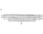
図2は、本発明の一実施形態におけるフラットパネルディスプレイ装置(以下、単にディスプレイ装置ということがある。)の概略側面図である。図3に示すように、ディスプレイ装置10は、表示パネル20と、カバーガラス30とを備える。 FIG. 2 is a schematic side view of a flat panel display device (hereinafter simply referred to as a display device) according to an embodiment of the present invention. As shown in FIG. 3, the
カバーガラス30は、主として、ディスプレイ装置10の美観や強度の向上、衝撃破損防止などを目的として設置する。カバーガラス30は、表示パネル20の前方に設置する。 The
例えば、カバーガラス30は、図2に示すように、表示パネル20の表示側(前側)から離間するように(空気の層を有するように)設置してもよい。この場合、カバーガラス30と、表示パネル20とは筐体12を介して一体化してもよい。 For example, as shown in FIG. 2, the
また、カバーガラス30は、図4に示すように、表示パネル20の表示側(前側)に貼り付けてもよい。例えば、カバーガラス30は、透光性を有する接着膜(図示せず)を介して、表示パネル20の表示側に貼り付ける。接着膜は、一般的な構成であってよく、その材質および形状は適宜選定される。 Moreover, the
図4に示すように、カバーガラス30と表示パネル20との間に空隙がない構成とすることによって、カバーガラス30(または、表示パネル20)と空隙との界面における光の反射を抑えることができる。その結果、ディスプレイ装置10の画質を高めることができる。また、ディスプレイ装置10の薄型化にも貢献することができる。 As shown in FIG. 4, by adopting a configuration in which there is no gap between the
カバーガラス30は、表示パネル20からの光を出射する前面31と、表示パネル20からの光が入射する背面32とを有する。前面31または/および背面32には、機能膜40が設けてもよい。なお、機能膜40は、図2では前面31および背面32に設けられており、図4では前面31に設けられている。 The
機能膜40は、例えば、周囲光の反射防止、衝撃破損防止、電磁波遮蔽、近赤外線遮蔽、色調補正、または/および耐傷性向上などの機能を有する。機能膜40は、例えば樹脂製の膜をカバーガラス30に貼り付けることにより形成する。あるいは、機能膜40は、蒸着法、スパッタ法およびCVD法などの薄膜形成法により形成してもよい。機能膜40は、一般的な構成であってもよく、その厚さおよび形状などは、用途に応じて適宜選択する。 The
カバーガラス30の背面32には、周縁部の少なくとも一部に沿って、加飾層50が設けられている。この加飾層50は、表示パネル20の外周を取り囲むように配置してもよい。加飾層50は、カバーガラス板30、ひいてはディスプレイ装置10のデザイン性および装飾性を高めるために設置する。 On the
例えば、加飾層50を黒色に着色すると、ディスプレイ装置10がオフ状態のときに、カバーガラス30の周縁部を含めて、カバーガラス30の前面31から全く光が出射されなくなる。従って、ディスプレイ装置10の外観がシャープな印象をユーザに与えるようになり、美観が向上する。 For example, when the
加飾層50の形成方法に制限はなく、例えば、顔料粒子を含むインクをカバーガラス30に塗布し、これを紫外線照射、または加熱焼成した後、冷却することによって形成する方法がある。 There is no restriction | limiting in the formation method of the
顔料粒子は、有機顔料、無機顔料などで構成され、顔料粒子を有機ビヒクルに混合、分散させることによりインクを調製する。 The pigment particles are composed of organic pigments, inorganic pigments, and the like, and ink is prepared by mixing and dispersing the pigment particles in an organic vehicle.
以下、本発明を実施例によって説明するが、本発明はこれらにより限定されるものではない。 EXAMPLES Hereinafter, although an Example demonstrates this invention, this invention is not limited by these.
フュージョン法により製造したガラス〔組成(モル%):SiO2 66.6%、Al2O3 10.8%、Na2O 13.2%、K2O 2.4%、MgO 6.2%、CaO 0.6%〕における欠点の粒子径(直径)を、38サンプルの光学顕微鏡写真を用いて測定し、各粒子径範囲での頻度を算出した。欠点の粒子径は、最大部分の長さを、対物マイクロメータの写真と比較することにより測定した。結果を図1の棒グラフに示す。Glass produced by the fusion method [Composition (mol%): SiO2 66.6%, Al2 O3 10.8%, Na2 O 13.2%, K2 O 2.4%, MgO 6.2% , CaO 0.6%], the particle diameter (diameter) of the defect was measured using optical micrographs of 38 samples, and the frequency in each particle diameter range was calculated. The particle size of the defect was measured by comparing the length of the maximum part with a photograph of the objective micrometer. The results are shown in the bar graph of FIG.
また、前記ガラスにおけるクラックの発生率を測定した。ここで、クラックの発生率は、顕微鏡写真において、クラックが発生しているかどうかを目視で判定することにより測定した。結果を図1の折れ線グラフに示す。 In addition, the incidence of cracks in the glass was measured. Here, the occurrence rate of cracks was measured by visually determining whether or not cracks occurred in a micrograph. The results are shown in the line graph of FIG.
図1の折れ線グラフに示すように、欠点の粒子径(直径)が40μm以上で、急激にクラックの発生率が高くなった。また、欠点の組成をEPMAにより解析したところ、ZrO2であった。この結果から、化学強化に供するガラス中に粒子径40μm以上の大きさの欠点がなければ、化学強化した場合に自発的な破壊が生じる可能性が非常に低いことが分かった。As shown in the line graph of FIG. 1, when the particle diameter (diameter) of the defect is 40 μm or more, the crack generation rate suddenly increased. Moreover, when the composition of the defect was analyzed by EPMA, it was ZrO2 . From this result, it was found that if the glass used for chemical strengthening does not have a defect having a particle size of 40 μm or more, the possibility of spontaneous destruction when chemically strengthened is very low.
10 ディスプレイ装置
20 表示パネル
30 カバーガラス
31 前面
32 背面
40 機能膜
50 加飾層DESCRIPTION OF
Claims (7)
Translated fromJapanesePriority Applications (5)
| Application Number | Priority Date | Filing Date | Title |
|---|---|---|---|
| JP2010280467AJP2012126615A (en) | 2010-12-16 | 2010-12-16 | Cover glass for flat panel display |
| US13/324,100US20120156464A1 (en) | 2010-12-16 | 2011-12-13 | Cover glass for flat panel displays |
| TW100146621ATW201231416A (en) | 2010-12-16 | 2011-12-15 | Cover glass for flat panel displays |
| CN2011104199646ACN102583966A (en) | 2010-12-16 | 2011-12-15 | Cover glass for flat panel displays |
| KR1020110136152AKR20120067966A (en) | 2010-12-16 | 2011-12-16 | Cover glass for flat panel display |
Applications Claiming Priority (1)
| Application Number | Priority Date | Filing Date | Title |
|---|---|---|---|
| JP2010280467AJP2012126615A (en) | 2010-12-16 | 2010-12-16 | Cover glass for flat panel display |
Publications (1)
| Publication Number | Publication Date |
|---|---|
| JP2012126615Atrue JP2012126615A (en) | 2012-07-05 |
Family
ID=46234788
Family Applications (1)
| Application Number | Title | Priority Date | Filing Date |
|---|---|---|---|
| JP2010280467AWithdrawnJP2012126615A (en) | 2010-12-16 | 2010-12-16 | Cover glass for flat panel display |
Country Status (5)
| Country | Link |
|---|---|
| US (1) | US20120156464A1 (en) |
| JP (1) | JP2012126615A (en) |
| KR (1) | KR20120067966A (en) |
| CN (1) | CN102583966A (en) |
| TW (1) | TW201231416A (en) |
Cited By (3)
| Publication number | Priority date | Publication date | Assignee | Title |
|---|---|---|---|---|
| JP2013116846A (en)* | 2011-01-18 | 2013-06-13 | Nippon Electric Glass Co Ltd | Tempered glass, and tempered glass plate |
| JP2014035544A (en)* | 2012-08-08 | 2014-02-24 | Panasonic Avionics Corp | System and method for improving impact safety |
| JPWO2014156906A1 (en)* | 2013-03-29 | 2017-02-16 | 旭硝子株式会社 | Method for evaluating optical characteristics of transparent substrate, optical apparatus |
Families Citing this family (3)
| Publication number | Priority date | Publication date | Assignee | Title |
|---|---|---|---|---|
| WO2012008586A1 (en) | 2010-07-15 | 2012-01-19 | 旭硝子株式会社 | Plasma display device |
| KR102080132B1 (en) | 2013-03-20 | 2020-02-24 | 삼성디스플레이 주식회사 | Cover window for display device, display device comprising the same, and mathod for manufacturing the same |
| DE112014003344T5 (en) | 2013-07-19 | 2016-03-31 | Asahi Glass Company, Limited | Chemically tempered glass |
Citations (4)
| Publication number | Priority date | Publication date | Assignee | Title |
|---|---|---|---|---|
| JPS517006A (en)* | 1974-07-08 | 1976-01-21 | Central Glass Co Ltd | GARASUGENRYOSOSEIBUTSU |
| JP2009167089A (en)* | 2007-12-19 | 2009-07-30 | Nippon Electric Glass Co Ltd | Glass substrate |
| JP2010527892A (en)* | 2007-05-18 | 2010-08-19 | コーニング インコーポレイテッド | Chemically reinforced glass for cover plates that can be manufactured by the downdraw method |
| JP2010275126A (en)* | 2008-05-30 | 2010-12-09 | Asahi Glass Co Ltd | Glass plate for display device |
Family Cites Families (7)
| Publication number | Priority date | Publication date | Assignee | Title |
|---|---|---|---|---|
| CN1289416C (en)* | 2001-12-21 | 2006-12-13 | 康宁股份有限公司 | Process for producing sheet glass by the overflow downdraw fusion process |
| US7727917B2 (en)* | 2003-10-24 | 2010-06-01 | Schott Ag | Lithia-alumina-silica containing glass compositions and glasses suitable for chemical tempering and articles made using the chemically tempered glass |
| KR20070086292A (en)* | 2004-12-16 | 2007-08-27 | 도꾸리쯔교세이호진 상교기쥬쯔 소고겡뀨죠 | The recipe of plate glass |
| JP5467490B2 (en)* | 2007-08-03 | 2014-04-09 | 日本電気硝子株式会社 | Method for producing tempered glass substrate and tempered glass substrate |
| WO2009099614A1 (en)* | 2008-02-08 | 2009-08-13 | Corning Incorporated | Damage resistant, chemically-toughened protective cover glass |
| US20100212359A1 (en)* | 2009-02-23 | 2010-08-26 | Hilary Tony Godard | Spinel isopipe for fusion forming alkali containing glass sheets |
| US8028544B2 (en)* | 2009-02-24 | 2011-10-04 | Corning Incorporated | High delivery temperature isopipe materials |
- 2010
- 2010-12-16JPJP2010280467Apatent/JP2012126615A/ennot_activeWithdrawn
- 2011
- 2011-12-13USUS13/324,100patent/US20120156464A1/ennot_activeAbandoned
- 2011-12-15CNCN2011104199646Apatent/CN102583966A/enactivePending
- 2011-12-15TWTW100146621Apatent/TW201231416A/enunknown
- 2011-12-16KRKR1020110136152Apatent/KR20120067966A/ennot_activeWithdrawn
Patent Citations (4)
| Publication number | Priority date | Publication date | Assignee | Title |
|---|---|---|---|---|
| JPS517006A (en)* | 1974-07-08 | 1976-01-21 | Central Glass Co Ltd | GARASUGENRYOSOSEIBUTSU |
| JP2010527892A (en)* | 2007-05-18 | 2010-08-19 | コーニング インコーポレイテッド | Chemically reinforced glass for cover plates that can be manufactured by the downdraw method |
| JP2009167089A (en)* | 2007-12-19 | 2009-07-30 | Nippon Electric Glass Co Ltd | Glass substrate |
| JP2010275126A (en)* | 2008-05-30 | 2010-12-09 | Asahi Glass Co Ltd | Glass plate for display device |
Cited By (3)
| Publication number | Priority date | Publication date | Assignee | Title |
|---|---|---|---|---|
| JP2013116846A (en)* | 2011-01-18 | 2013-06-13 | Nippon Electric Glass Co Ltd | Tempered glass, and tempered glass plate |
| JP2014035544A (en)* | 2012-08-08 | 2014-02-24 | Panasonic Avionics Corp | System and method for improving impact safety |
| JPWO2014156906A1 (en)* | 2013-03-29 | 2017-02-16 | 旭硝子株式会社 | Method for evaluating optical characteristics of transparent substrate, optical apparatus |
Also Published As
| Publication number | Publication date |
|---|---|
| US20120156464A1 (en) | 2012-06-21 |
| KR20120067966A (en) | 2012-06-26 |
| CN102583966A (en) | 2012-07-18 |
| TW201231416A (en) | 2012-08-01 |
Similar Documents
| Publication | Publication Date | Title |
|---|---|---|
| JP5838967B2 (en) | Cover glass for flat panel display and manufacturing method | |
| US9598307B2 (en) | Glass and glass substrate | |
| US10173922B2 (en) | Glass | |
| US10351466B2 (en) | Glass | |
| JP5929898B2 (en) | Chemically tempered glass for display devices | |
| JP6075661B2 (en) | Method for producing tempered glass plate and method for producing tempered glass plate | |
| TWI380967B (en) | Glass plate and manufacturing method thereof, and manufacturing method of TFT panel | |
| WO2012008586A1 (en) | Plasma display device | |
| WO2012043482A1 (en) | Glass for chemical strengthening, chemically strengthened glass, and glass plate for display device | |
| US20140235425A1 (en) | Glass substrate and method for producing same | |
| WO2014175144A1 (en) | Glass plate for chemical reinforcement purposes, and method for producing same | |
| JP5459122B2 (en) | Display device | |
| JP2012126615A (en) | Cover glass for flat panel display | |
| WO2012108417A1 (en) | Tempered glass plate | |
| JP2008195602A (en) | Method for manufacturing tempered glass substrate and tempered glass substrate | |
| WO2011085141A1 (en) | Cover assembly for electronic display devices | |
| CN107922258A (en) | chemically strengthened glass | |
| WO2014002932A1 (en) | Glass substrate for organic el device and manufacturing method therefor | |
| WO2014185486A1 (en) | Glass plate for tempering, tempered glass plate, and method for manufacturing tempered glass plate | |
| JP2012018207A (en) | Liquid crystal display device and cover glass plate | |
| KR20180086594A (en) | Thermosetting glass for display having grooves of module cover fixing plate and manufacturing method thereof | |
| WO2022039056A1 (en) | Chemically strengthened glass | |
| JP2014019627A (en) | Strengthened glass and display device | |
| JP6075713B2 (en) | Cover glass for display | |
| US20220204385A1 (en) | Glass substrate |
Legal Events
| Date | Code | Title | Description |
|---|---|---|---|
| A621 | Written request for application examination | Free format text:JAPANESE INTERMEDIATE CODE: A621 Effective date:20130808 | |
| RD04 | Notification of resignation of power of attorney | Free format text:JAPANESE INTERMEDIATE CODE: A7424 Effective date:20140210 | |
| A977 | Report on retrieval | Free format text:JAPANESE INTERMEDIATE CODE: A971007 Effective date:20140731 | |
| A131 | Notification of reasons for refusal | Free format text:JAPANESE INTERMEDIATE CODE: A131 Effective date:20140826 | |
| A761 | Written withdrawal of application | Free format text:JAPANESE INTERMEDIATE CODE: A761 Effective date:20140929 |